

Page 1
SR-R1
(SY)
4-400-203-02 (1)
Sony Corporation
Printed on recycled paper.
Printed in Japan
2011.11 32
© 2011
PORTABLE MEMORY RECORDER
SR-R1
OPERATION MANUAL [English]
1st Edition (Revised 1)
Page 2

Before operating the unit, please read this
manual thoroughly and retain it for future
reference.
WARNING
To reduce the risk of fire or
electric shock, do not
expose this apparatus to
rain or moisture.
To avoid electrical shock,
do not open the cabinet.
Refer servicing to qualified
personnel only.
Do not install the appliance in a confined
space, such as book case or built-in cabinet.
IMPORTANT
The nameplate is located on the bottom.
WARNING
Excessive sound pressure from earphones
and headphones can cause hearing loss.
In order to use this product safely, avoid
prolonged listening at excessive sound
pressure levels.
For the customers in the U.S.A.
This equipment has been tested and found
to comply with the limits for a Class B digital
device, pursuant to Part 15 of the FCC
Rules. These limits are designed to provide
reasonable protection against harmful
interference in a residential installation. This
equipment generates, uses, and can radiate
radio frequency energy and, if not installed
and used in accordance with the
instructions, may cause harmful interference
to radio communications. However, there is
no guarantee that interference will not occur
in a particular installation. If this equipment
does cause harmful interference to radio or
television reception, which can be
determined by turning the equipment off and
on, the user is encouraged to try to correct
the interference by one or more of the
following measures:
- Reorient or relocate the receiving
antenna.
- Increase the separation between the
equipment and receiver.
- Connect the equipment into an outlet on a
circuit different from that to which the
receiver is connected.
- Consult the dealer or an experienced
radio/TV technician for help.
You are cautioned that any changes or
modifications not expressly approved in this
manual could void your authority to operate
this equipment.
All interface cables used to connect
peripherals must be shielded in order to
comply with the limits for a digital device
pursuant to Subpart B of Part 15 of FCC
Rules.
This device complies with Part 15 of the FCC
Rules. Operation is subject to the following
two conditions: (1) this device may not cause
harmful interference, and (2) this device
must accept any interference received,
including interference that may cause
undesired operation.
For the customers in Canada
This Class B digital apparatus complies with
Canadian ICES-003.
For the customers in Europe
This product with the CE marking complies
with the EMC Directive issued by the
Commission of the European Community.
Compliance with this directive implies
conformity to the following European
standards:
• EN55103-1 : Electromagnetic
Interference(Emission)
• EN55103-2 : Electromagnetic
Susceptibility(Immunity)
This product is intended for use in the
following Electromagnetic Environments: E1
(residential), E2 (commercial and light
industrial), E3 (urban outdoors), E4
(controlled EMC environment, ex. TV
studio).
2
Page 3
For the customers in Europe
The manufacturer of this product is Sony
Corporation, 1-7-1 Konan, Minato-ku,
Tokyo, Japan.
The Authorized Representative for EMC and
product safety is Sony Deutschland GmbH,
Hedelfinger Strasse 61, 70327 Stuttgart,
Germany. For any service or guarantee
matters please refer to the addresses given
in separate service or guarantee documents.
For the State of California, USA only
Perchlorate Material - special handling may
apply, See
www.dtsc.ca.gov/hazardouswaste/
perchlorate
Perchlorate Material : Lithium battery
contains perchlorate.
For the customers in Taiwan only
Avant d'utiliser l'appareil, veuillez lire
attentivement ce manuel et le conserver
pour future référence.
AVERTISSEMENT
Afin de réduire les risques
d’incendie ou
d’électrocution, ne pas
exposer cet appareil à la
pluie ou à l’humidité.
Afin d’écarter tout risque
d’électrocution, garder le
coffret fermé. Ne confier
l’entretien de l’appareil
qu’à un personnel qualifié.
Ne pas installer l’appareil dans un endroit
confiné, par exemple une bibliothèque ou un
placard encastré.
IMPORTANT
La plaque signalétique se situe sous
l’appareil.
AVERTISSEMENT
Une pression acoustique excessive en
provenance des écouteurs ou du casque
peut provoquer une baisse de l'acuité
auditive.
Pour utiliser ce produit en toute sécurité,
évitez l'écoute prolongée à des pressions
sonores excessives.
Pour les clients au Canada
Cet appareil numérique de la classe B est
conforme à la norme NMB-003 du Canada.
Pour les clients en Europe
Ce produit portant la marque CE est
conforme à la Directive sur la compatibilité
électromagnétique (EMC) émise par la
Commission de la Communauté
européenne.
La conformité à cette directive implique la
conformité aux normes européennes
suivantes :
3
Page 4

• EN55103-1 : Interférences
électromagnétiques (émission)
• EN55103-2 : Sensibilité
électromagnétique (immunité)
Ce produit est prévu pour être utilisé dans
les environnements électromagnétiques
suivants : E1 (résidentiel), E2 (commercial et
industrie légère), E3 (urbain extérieur) et E4
(environnement EMC contrôlé, ex. studio de
télévision).
Pour les clients en Europe
Le fabricant de ce produit est Sony
Corporation, 1-7-1 Konan, Minato-ku,
Tokyo, Japon.
Le représentant autorisé pour EMC et la
sécurité des produits est Sony Deutschland
GmbH, Hedelfinger Strasse 61, 70327
Stuttgart, Allemagne. Pour toute question
concernant le service ou la garantie, veuillez
consulter les adresses indiquées dans les
documents de service ou de garantie
séparés.
Bitte lesen Sie dieses Handbuch vor der
Benutzung des Geräts sorgfältig durch und
bewahren Sie es zum späteren
Nachschlagen auf.
WARNUNG
Um die Gefahr von Bränden
oder elektrischen Schlägen
zu verringern, darf dieses
Gerät nicht Regen oder
Feuchtigkeit ausgesetzt
werden.
Um einen elektrischen
Schlag zu vermeiden, darf
das Gehäuse nicht geöffnet
werden. Überlassen Sie
Wartungsarbeiten stets nur
qualifiziertem
Fachpersonal.
Das Gerät nicht an Orten aufstellen, z.B. in
Bücherregalen oder Einbauschränken, wo
keine ausreichende Belüftung gewährleistet
ist.
WICHTIG
Das Namensschild befindet sich auf der
Unterseite des Gerätes.
WARNUNG
Zu hoher Schalldruck von Ohrhörern und
Kopfhörern kann Gehörschäden
verursachen.
Um dieses Produkt sicher zu verwenden,
vermeiden Sie längeres Hören bei sehr
hohen Schalldruckpegeln.
Für Kunden in Europa
Dieses Produkt besitzt die CEKennzeichnung und erfüllt die EMVRichtlinie der EG-Kommission.
Angewandte Normen:
• EN55103-1: Elektromagnetische
Verträglichkeit (Störaussendung)
4
Page 5

• EN55103-2: Elektromagnetische
Verträglichkeit (Störfestigkeit)
Für die folgenden elektromagnetischen
Umgebungen: E1 (Wohnbereich), E2
(kommerzieller und in beschränktem Maße
industrieller Bereich), E3 (Stadtbereich im
Freien) und E4 (kontrollierter EMV-Bereich,
z.B. Fernsehstudio).
Für Kunden in Europa
Der Hersteller dieses Produkts ist Sony
Corporation, 1-7-1 Konan, Minato-ku,
Tokyo, Japan.
Der autorisierte Repräsentant für EMV und
Produktsicherheit ist Sony Deutschland
GmbH, Hedelfinger Strasse 61, 70327
Stuttgart, Deutschland. Bei jeglichen
Angelegenheiten in Bezug auf Kundendienst
oder Garantie wenden Sie sich bitte an die in
den separaten Kundendienst- oder
Garantiedokumenten aufgeführten
Anschriften.
5
Page 6

Table of Contents
Chapter 1 : Overview
Features................................................... 8
System Configuration Example............ 9
Names of Parts...................................... 10
Overall View ............................. 10
Left Side View........................... 10
Rear and Right Side View......... 11
Control Panel............................. 12
Display....................................... 13
Chapter 2 : Preparation
Work Flow ............................................ 15
Mount Control Panel........................... 15
Connect Power .................................... 16
Using AC Power........................ 16
Using the Battery Pack.............. 16
Connect HD SDI Compliant
Equipment ...................................... 19
Connecting a Camera/
Camcorder........................... 19
Connecting an HD Monitor....... 20
About the Reference Sync
Signal ................................. 21
Turn Power On .................................... 22
Insert SRMemory Card ..................... 23
Inserting and Removing the
SRMemory Card ................. 23
Formatting an SRMemory Card
(File System Format ) ......... 24
Chapter 3 : Basic Menu Operations
Locking the Controls................. 26
Signal Format Settings......................... 27
Selecting the Signal Format....... 27
Display Settings .................................... 28
Using the Backlight ................... 28
Using the Screen Saver.............. 28
Date Settings ......................................... 28
Chapter 4 : Recording and Playback
Recording Preparations and
Operations ...................................... 29
Setting the Audio Signals .......... 29
Setting the Recording Levels..... 30
Setting the Time Code and User
Bits ..................................... 31
Recording .................................. 33
Playback Preparations and
Operations ...................................... 34
Making Settings Related to Audio
Monitor Signals................... 34
Adjusting Playback Audio
Levels ................................. 34
Selecting the Time Data to Display
During Playback.................. 34
Playback .................................... 35
How to Use the Recording and Playback
Operation Buttons.......................... 36
Making Superimpose Settings............. 37
FILE LIST Operations........................ 38
Displaying a File List ................ 38
Performing File Operations....... 39
Changing the File Display
Order ................................... 40
Table of Contents
6
Buttons Used for Menu
Operations........................... 25
Serve for Selecting a Menu ....... 25
Page 7

Chapter 5 : Menu Details
TC Setup Menu .................................... 41
AUDIO Setup Menu ............................ 44
SYSTEM Setup Menu ......................... 46
Appendix
Maintenance and Inspections.............. 49
Note About the Power Supply
Terminal.............................. 49
Specifications........................................ 49
General ...................................... 49
Video ......................................... 50
Audio......................................... 50
Input/Output Connectors ........... 50
Supplied Accessories................. 51
Optional Accessories................. 51
Error Messages and Warning
Messages ......................................... 52
About Error Messages............... 52
About Warning Messages ......... 52
Warning System................................... 53
Troubleshooting ................................... 54
About Recording/
Playback Formats.......................... 58
MPEG-4 VISUAL PATENT
PORTFOLIO LICENSE............... 59
Index...................................................... 60
Table of Contents
7
Page 8

Chapter 1 Overview
Chapter 1 Overview
Features
The SR-R1 is a portable memory recorder of the
SRMASTER series that has 1.5G SDI Dual Link
input/output and uses the newly developed
SRMemory card for recording media.
SRMASTER and SRMemory are trademarks of
Sony Corporation.
High Quality Recording
Support for SR-SQ (440 Mbps) and SR-Lite
(220 Mbps) is provided as standard.
There is 16-channel (uncompressed, 24-bit,
48 kHz) support for audio.
RGB 4:4:4/60p Creation
The SR-R1 is equipped with 1.5G SDI Dual Link
and includes recording capabilities such as RGB
4:4:4 and 60p to enable support for various
scenes.
card in the PMW-F3 and the SRMemory card is
possible.
HD SDI Remote
Support is provided for the HD SDI Remote
function that is incorporated in many Sony
camcorders, so recording can be linked to Rec/
Stop on the camera side.
HDW-F900R/650 dockable operation
The SR-R1 supports dockable operation with the
HD CAM camcorder HDW-F900R/650 equipped
with HD SDI output, using the Docking Plate
SRK-R302 (sold separately).
Use as PMW-F3 storage
The SR-R1 can be used as high-quality online
storage for the Digital Cinema Recorder PMWF3. Simultaneous recording on the SxS memory
Features
8
Page 9
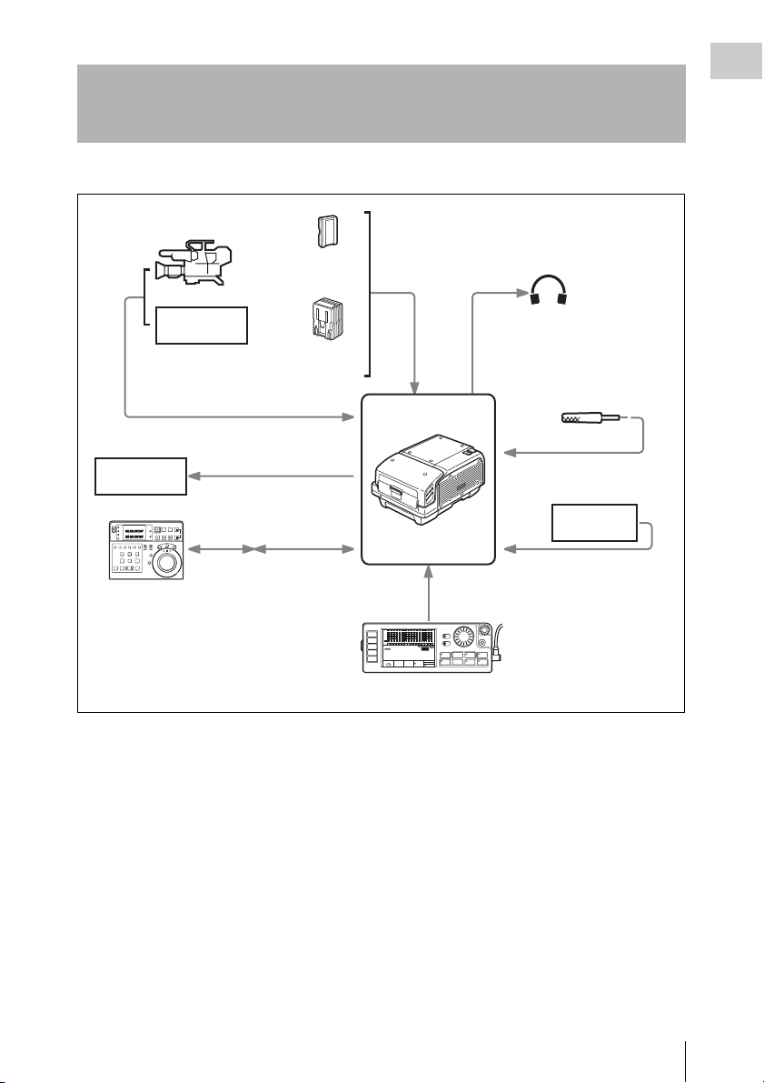
System Configuration Example
The following figure shows a system configured around the SR-R1.
HD color video camera
BP-GL95
+
BKP-L551
HD VTR etc.
AC-DN10
HD SDI video/
audio input
DC IN
Earphones/
Headphones
Audio input
Chapter 1 Overview
HD VTR etc.
RM-280
Editing Controller
HD SDI video/audio output
9-pin
remote
control
REMOTE
cable (included)
REMOTE IN
(planned for
support)
SR-R1
CTRL PANEL
SDI
SDI
SDI
SDI
SDI
SDI
SDI
SDI
SDI
SDI
SDI
SDI
SDI
SDI
SDI
SDI
dB
0
-10
HOME
-20
-30
-60
EE
TC
VIDEO
TCG
AUDIO
00H00 M00S 00F
SYSTEM
16.5V
EMP
LR
1
KEY INHI
OFF ON
EMP
EMP
EMP
EMP
EMP
EMP
EMP
EMP
EMP
EMP
EMP
EMP
EMP
LR
LR
LR
LR
LR
LR
LR
LR
LR
LR
LR
LR
LR
2
3
4
5
6
7
8
9
10
11
12
13
14
SR-R1
STOP
KEY
INHI
LOCAL
1920x1080
ENCODE
REMAIN
M
59.94I
SR-SQ
10min
4:2:2
10bit
21:46
SELECT/ENTER
EMP
EMP
LIGHT
LR
LR
15
16
OFF ON
ADJUST
RECINHI
EJECT STOP PLAY
REC
xZzB
REW F FWD PAUSE
FUNC
mXM
EE
Control Panel (included)
Microphone
Analog: 2 channels
Audio input
VTR etc.
AUX IN:16 channels
BACK
System Configuration Example
9
Page 10
Chapter 1 Overview
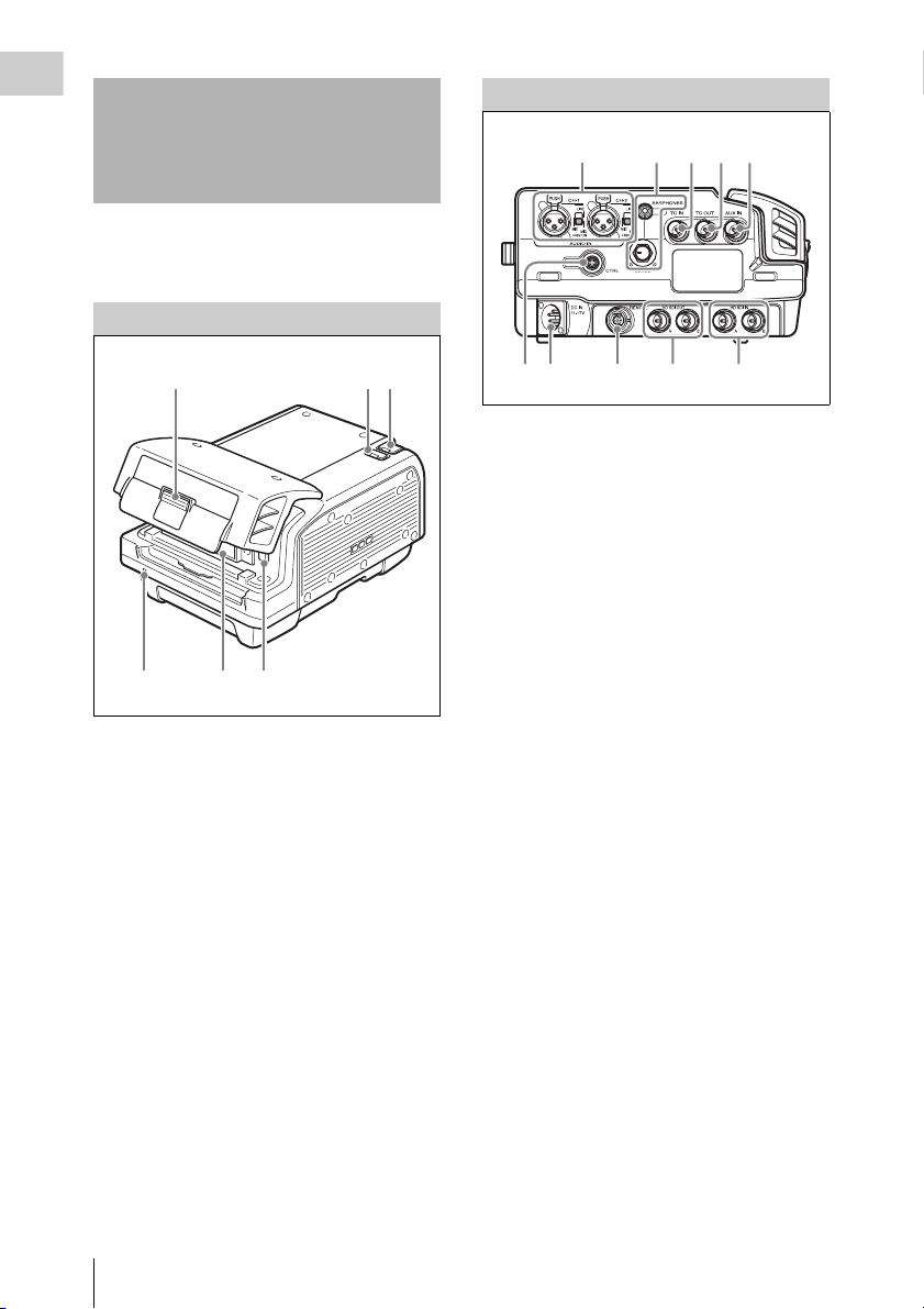
Names of Parts
For detailed information on functions and usage, see
the pages indicated in brackets.
Overall View
Left Side View
321
4 5
1
4
56
23
1. Lid open/close button (page 23)
2. Tally indicator (page 22)
Lights up during recording.
Flashes as a warning indication when an
error or problem has occurred.
3. POWER (power supply) indicator
(page 22)
Lights up in green when power to the unit is
on.
4. EJECT button (page 24)
5. SRMemory card slot (page 23)
6. LID LOCK indicator (page 23)
Lights up in orange when an SRMemory card
is mounted.
10 9 8 7 6
1. AUDIO INPUT CH-1, CH-2 (analog audio
input channel 1, 2) connectors (3-pin XLR,
female) and input selection switches
Set the input selection switches as follows,
depending on the type and level of the input
audio.
LINE: For line input
MIC: For microphone input
MIC +48V ON: For input from microphones
with external power supply
2. EARPHONES jack (stereo mini jack) and
LEVEL knob
Adjusts the audio level.
A warning/alarm tone is also output via this
jack when an error is detected.
3. TC IN (time code input) connector (BNC)
Connect to the time code output connector of
an external device such as a time code
generator or VTR. Use this connector when
locking the internal time code generator to
external time code.
4. TC OUT (time code output) connector
(BNC)
Connect to the time code input connector of
an external device such as a time code reader
or VTR. Signal is supplied according to
setting made from TC Setup menu, OTHERS
>TC OUT. (see page 42)
5. AUX IN (SDI embedded audio input)
connector (BNC) (page 44)
Accepts audio input in up to 16 channels.
6. HD SDI IN (HD SDI signal input) A/B
(BNC) (page 19)
7. HD SDI OUT (MON) (HD SDI signal
output) connectors 1/2 (BNC) (page 19)
10
Names of Parts
Page 11
8. REMOTE (remote control input)
connector (14-pin, female) (for future
expansion)
9. DC IN (DC power input) connector (4-pin
XLR, male) (page 16)
10. CTRL PANEL (Control Panel) connector
(page 16)
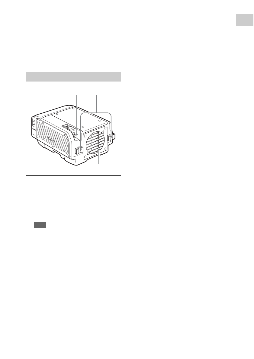
Rear and Right Side View
Chapter 1 Overview
1
2
3
1. Power switch (page 22)
Setting the switch to the ? side turns power
on, and setting the switch to the 1 side turns
power off.
2. Cable clamp (page 16)
3. Fan
Note
Do not block the ventilation openings.
Otherwise internal heat buildup can lead to a risk of
fire and damage to the unit.
Names of Parts
11
Page 12
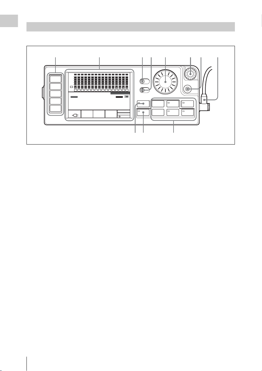
Control Panel
Chapter 1 Overview
For information on how to use the control panel, see “Basic Menu Operations” (page 25).
1
HOME
TC
VIDEO
AUDIO
SYSTEM
SDI
SDI
dB
0
-10
-20
-30
-60
EMP
EMP
EE
L R
L R
1
2
TCG
00H 00M 00S 00F
16.5V
2345678
SDI
SDI
SDI
SDI
SDI
SDI
SDI
SDI
SDI
SDI
EMP
EMP
EMP
EMP
EMP
EMP
EMP
EMP
EMP
L R
7
ENCODE
SR-SQ
10bit
EMP
L R
L R
L R
L R
L R
8
9
10
11
12
1920x1080
59.94I
4:2:2
L R
L R
L R
L R
3
4
5
6
STOP
REMAIN
10min
1. Menu selection buttons (page 25)
For information on menu items, see “Menu
Details” (page 41).
2. Display (page 13)
3. KEY INHI (key inhibit) switch (page 26)
4. LIGHT switch (page 28)
Setting this switch to ON turns the backlight
on.
5. ADJUST knob
Serves to adjust audio levels etc.
6. SELECT/ENTER dial (page 25)
Serves to make menu selections etc. Rotate
the dial to move the cursor and press the dial
to change and confirm settings.
7. BACK button (page 25)
When a menu is displayed, you can press this
button to back up one level in the menu
structure.
8. Control panel connection cable (page 16)
9. Record/Play buttons (page 33, 35, 36)
Use these buttons to play recordings and
files.
The functions of the buttons change when
they are pressed together with the FUNC
button.
10. FUNC (Function) button (page 36)
Holding down this button changes the
operation of the Record/Play buttons.
11. EJECT button and indicator (page 24)
SDI
SDI
SDI
SDI
SR-R1
OFF ON
EMP
EMP
EMP
L R
L R
L R
OFF ON
14
15
16
INHI
RECINHI
LOCAL
EE
21:46
EMP
L R
13
KEY
11 10 9
Note on faulty pixels on the LCD panel
The LCD panel fitted to this unit is manufactured
with high precision technology, giving a
functioning pixel ratio of at least 99.99%. Thus a
very small proportion of pixels maybe “stuck”,
either always off (black), always on (red, green,
or blue), or flashing. In addition, over a long
period of use, because of the physical
characteristics of the liquid crystal display, such
“stuck” pixels may appear spontaneously. These
problems are not a malfunction. Note that any
such problems have no effect on recorded data.
KEY INHI
LIGHT
ADJUST
EJECT STOP PLAY
xZzB
REW F FWD PAUSE
FUNC
mXM
SELECT/ENTER
BACK
REC
12
Names of Parts
Page 13
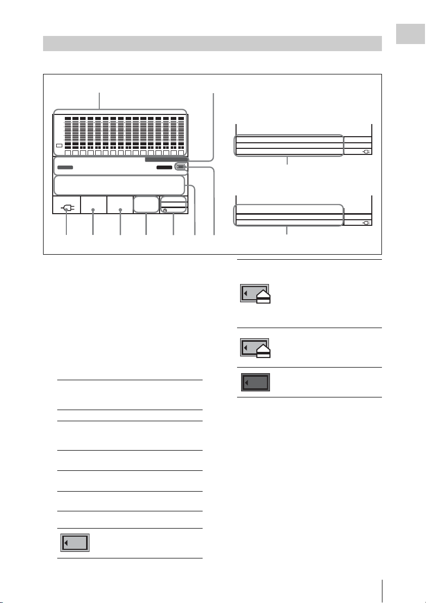
Display
00H00M00S00
00H06M00S00
The condition shown below is called the HOME screen in this manual.
Chapter 1 Overview
12
SDI
SDI
SDI
SDI
SDI
SDI
SDI
SDI
SDI
SDI
SDI
SDI
SDI
SDI
SDI
dB
0
-10
-20
-30
-60
EMP
EMP
EMP
EMP
EMP
EMP
EMP
EMP
EMP
EMP
EE
L R
L R
L R
L R
L R
1
TCG
L R
2
3
4
5
6
STOP
EMP
L R
L R
L R
L R
L R
7
L R
8
9
10
11
12
SDI
EMP
EMP
EMP
EMP
EMP
L R
L R
L R
L R
13
14
15
16
SR-R1
KEY
INHI
RECINHI
00H 00M 00S 00F
4:2:2
LOCAL
21:46
EE
16.5V
10min
SR-SQ
10bit
59.94I
1920x1080
ENCODE
REMAIN
1. Audio level meters
Show the recording level in recording and EE mode. During playback, the meters show
the playback level.
The top row indicates the audio input signal
that is being recorded.
The numbers 1 to 16 in the bottom row
indicate the track number of the file.
2. Operation status and warning indicator
Shows the operation status of the unit as well
as various warning indications.
TCR/TCG/
Time data type.
UBR/UBG/
TM1/TM2
LTC/VITC Time code is being shown.
DF/NDF System is in DF (drop-frame) or
NDF (non-drop frame) mode.
(see page 42)
EXT-LK Time code is locked to external
time code.
KEY INHI KEY INHI switch is ON. (see
page 26)
REC INHI SRMemory card is write-
protected. (see page 24)
3. SRMemory card icon indications
Mounting/mounted
An SRMemory card is inserted
and the lid is locked.
Sections 4 to 7 change to the condition
shown as 10 below when the HOME
button is pressed while holding down the
FUNC button.
F
SYS:
1920x1080 59.94I 4:2:2
ENCODE:
FILENAME:
SR-SQ 10bit
FILE00000015
LOCAL
60min
16.6V
10
PB:
1920x1080 59i 422 SR-SQ 10bit
DATE:
20/Oct/2011 20:13:52:16
DURATION:
4356789
00:00:00:24
10
Unmounting (cursor section in the
bottom right flashes)
The EJECT button has been
pressed and the unit is
transitioning to the state in which
you can remove the SRMemory
card.
UNMOUNT state
The lid lock has been released and
the SRMemory card can be
removed.
SRMemory card OUT state (off)
There is no SRMemory card in the
unit.
4. Time data indication
Shows the time data for the current position
in the file.
5. Status indication
Shows the control mode of the unit
(REMOTE/LOCAL), power mode (PB/EE),
and current time.
6. Signal format indication
Shows the format of the signal being
recorded.
7. Encoding format indication (page 58)
Shows the encoding and bit rate settings used
for recording.
LOCAL
60min
16.6V
F
Names of Parts
13
Page 14
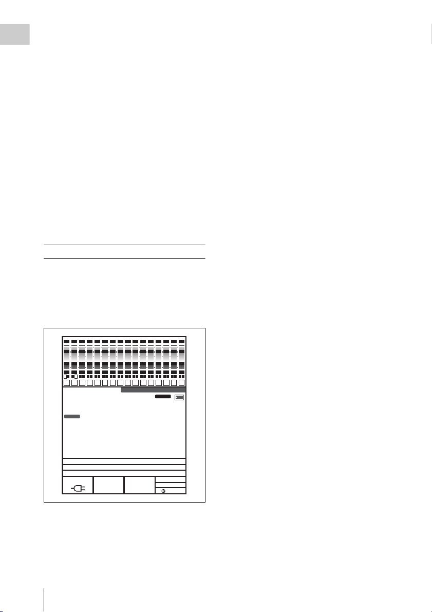
8. SRMemory card remaining capacity
Chapter 1 Overview
indication (page 23)
Shows the remaining space on the
SRMemory card calculated as remaining
time, using the current recording settings.
When the remaining time is less than 3
minutes, the indication flashes.
9. Battery/External power supply voltage
indication (page 22)
Shows the battery or external power supply
voltage.
10. Signal format/file information indication
(page 27)
When the FUNC and HOME buttons are
pressed simultaneously, the signal formats
are displayed from top to bottom in system,
encoding, playback file name sequence, or in
playback file output, recording date, duration
sequence.
To switch display to portrait mode
Press the HOME button while holding down the
FUNC and BACK buttons to switch the di splay to
portrait mode (rotate display 90° to the left).
To return to landscape mode, press the HOME
button again while holding down the FUNC and
BACK buttons.
14
SDI
SDI
SDI
SDI
SDI
SDI
SDI
SDI
SDI
SDI
SDI
EM
EM
EM
EM
EM
EM
EM
EM
EM EM
L R
1
L R
L R
L R
L R
L R
2
TCG
L R
3
4
5
6
STOP
EM
L R
L R
L R
L R
7
8
9
10
11
00H00M04S22
SYS:1920x1080 59.94P 4:2:2
ENCODE:SR-SQ 10bit
FileName:FILE00000144
16.7V
Names of Parts
REMAIN
77min
1920x1080
23.98PsF
4:2:2
SDI
L R
12
SR-R1
SDI
SDI
SDI
SDI
EM
EM
EM
EM
EM
L R
L R
L R
L R
13
14
15
16
KEY
INHI
RECINHI
F
LOCAL
EE
19:47
Page 15
Chapter 2 Preparation
Work Flow
The steps that are required before starting to use
the SR-R1 are listed below.
Mount control panel (page 15)
Connect power (page 16)
Connect HD SDI compliant equipment (page 19)
Turn power on (page 22)
Insert SRMemory card (page 23)
Tip
A Phillips (cross head) screwdriver is required for
mounting the control panel.
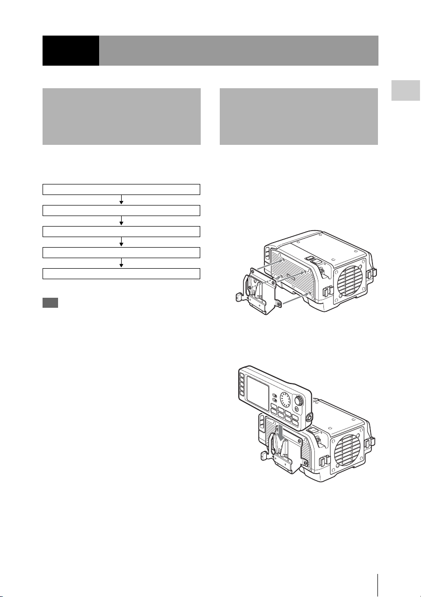
Mount Control Panel
Attach the supplied CP bracket to the unit, and
connect the unit and the control panel with the
control panel cable.
1 Attach the supplied CP bracket to the
right side of the unit.
2 Slide the control panel into the CP
bracket.
Chapter 2 Preparation
Work Flow / Mount Control Panel
15
Page 16
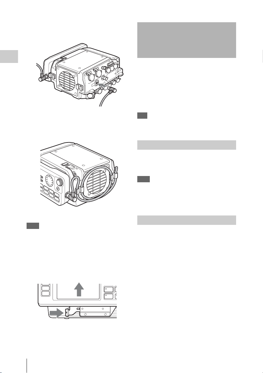
3 Use the supplied control panel cable to
connect the unit and the control panel.
Connect Power
Chapter 2 Preparation
4 Use the cable clamp as shown, to fix the
cable.
Note
Always turn off the power supply for the unit before
disconnecting the control panel cable and removing the
control panel.
To remove the control panel
Grasp the underside of the CP bracket and push it
in the B direction to release the lock. Then slide
the control panel out.
The SR-R1 can be powered either from a battery
pack or AC power.
For safety, do not use any AC adapter or battery
pack other than the Sony products specified
below.
• AC adapter: AC-DN10
• Lithium ion battery pack: BP-GL95
Tip
To use the battery pack, the Battery Adapter BKP-L551
(sold separately) is required.
Using AC Power
Use the DC power cable (sold separately) to
connect the AC adapter AC-DN10 to the DC IN
connector on the SR-R1.
Note
When connecting the output of a battery to the DC IN
connector, access the SYSTEM Setup menu and set the
BATTERY >DC IN TYPE option to other than “AC
Adapter.” (see page 48)
Using the Battery Pack
Before using the battery pack, charge it fully with
the dedicated battery charger.
For detailed information on charging, refer to the
documentation of the battery charger.
WARNING
Batteries shall not be exposed to excessive heat
such as sunshine, fire or the like.
CAUTION
Danger of explosion if battery is incorrectly
replaced.
Replace only with the same or equivalent type
recommended by the manufacturer.
When you dispose of the battery, you must obey
the law in the relative area or country.
AVERTISSEMENT
N’exposez pas les batteries à une chaleur
excessive, au soleil ou près d’un feu par exemple.
16
Connect Power
Page 17
ATTENTION
Il y a danger d’explosion s’il y a remplacement
incorrect de la batterie. Remplacer uniquement
avec une batterie du même type ou d’un type
équivalent recommandé par le constructeur.
Lorsque vous mettez la batterie au rebut, vous
devez respecter la législation en vigueur dans le
pays ou la région où vous vous trouvez.
WARNUNG
Akkus dürfen keinesfalls übermäßiger
Wärmeeinwirkung ausgesetzt werden, wie z.B.
Sonneneinstrahlung, Feuer o. ä.
VORSICHT
Explosionsgefahr bei Verwendung falscher
Batterien. Batterien nur durch den vom Hersteller
empfohlenen oder einen gleichwertigen Typ
ersetzen.
Wenn Sie die Batterie entsorgen, müssen Sie die
Gesetze der jeweiligen Region und des jeweiligen
Landes befolgen.
Battery pack usage precautions
• If the battery pack is charged immediately after
use while still warm, a full charge may not be
achieved.
• If not using the unit for an extended period,
detach the battery pack.
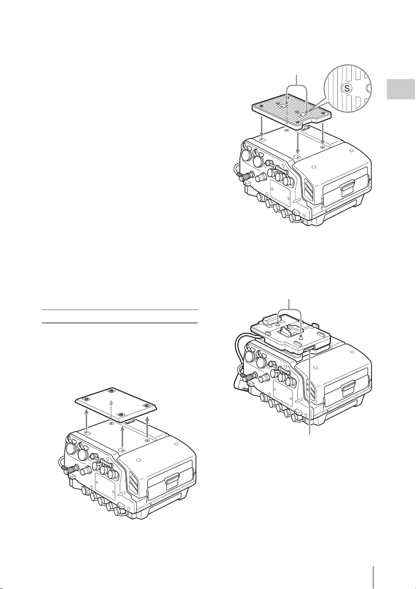
Attaching the battery pack
Use the BKP spacer supplied with the unit and the
separately available BKP-L551 to attach the
battery pack to the top of the unit.
2 Attach the supplied BKP spacer.
The S symbol must face up.
S symbols
Chapter 2 Preparation
3 Attach the BKP-L551 to the screw
threads marked with the S symbol and
connect the power cable to the DC IN
connector.
BKP-L551 fastening L screws
1 Remove the top cover of the unit.
BKP-L551 fastening L wrench
Connect Power
17
Page 18
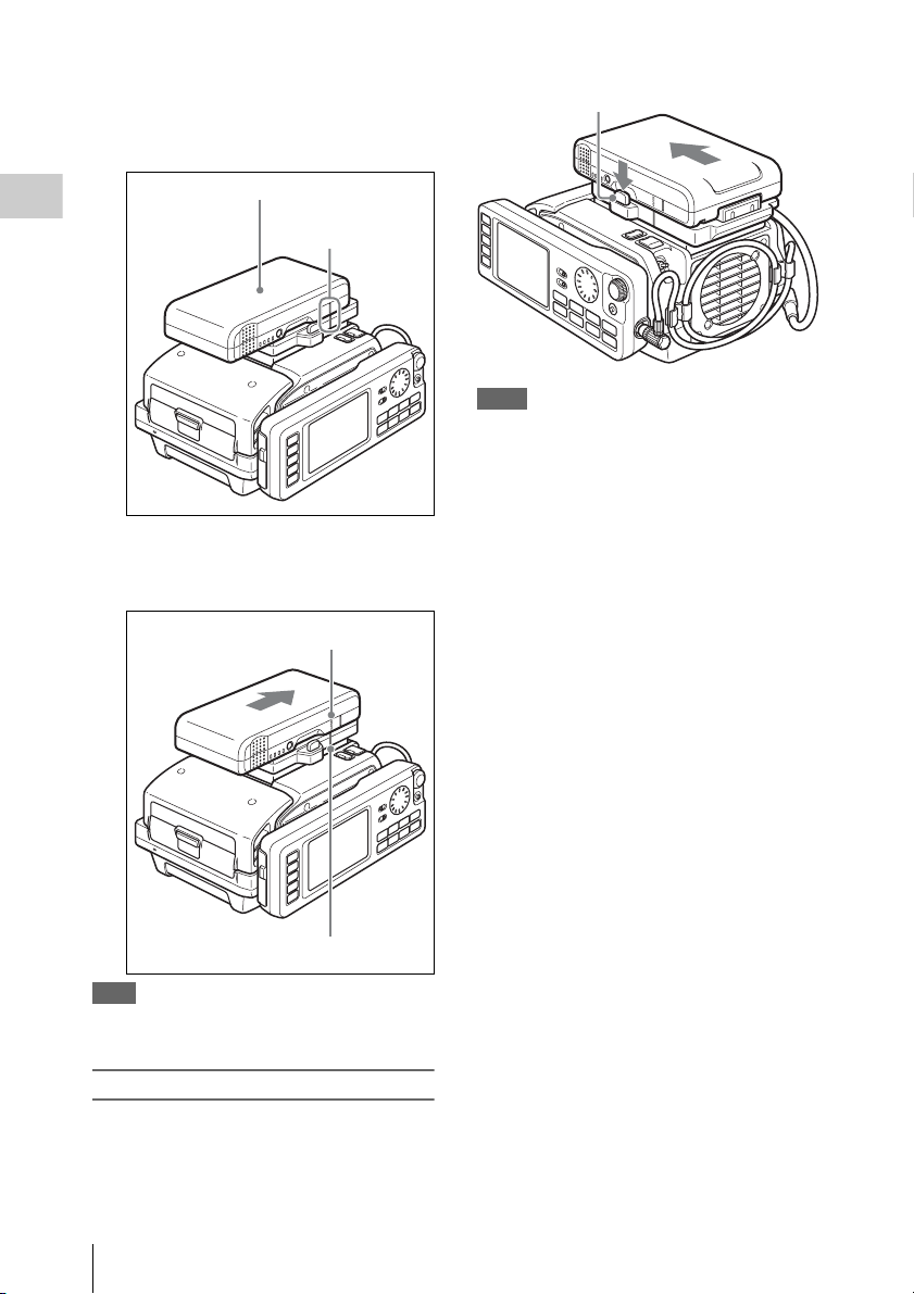
4 Align the line on the side of the battery
pack with the line on the unit and place
the battery pack on the rear section of
the unit.
1 Battery pack
Chapter 2 Preparation
2 Main unit/battery
pack line
5 Push the battery pack down and slide it
in the arrow direction marked
“LOCK.”
1 “LOCK” arrow
Lock release button
Notes
• Never remove the battery pack while a recording is in
progress (tally indicator is lit in red).
• Always turn power to the unit off before removing the
battery pack.
2 Line on main unit
Note
If the battery pack is attached incorrectly, the connectors
may be damaged.
Removing the battery pack
While power to the unit is switched off, hold
down the lock release button and push the battery
pack off.
Connect Power
18
Page 19
Connect HD SDI Compliant Equipment
Connect equipment with an HD SDI interface to the HD SDI IN (MON) (HD SDI signal input) connector
A/B and HD SDI OUT (HD SDI output) connector A/B of the SR-R1.
Representative connection examples are shown below.
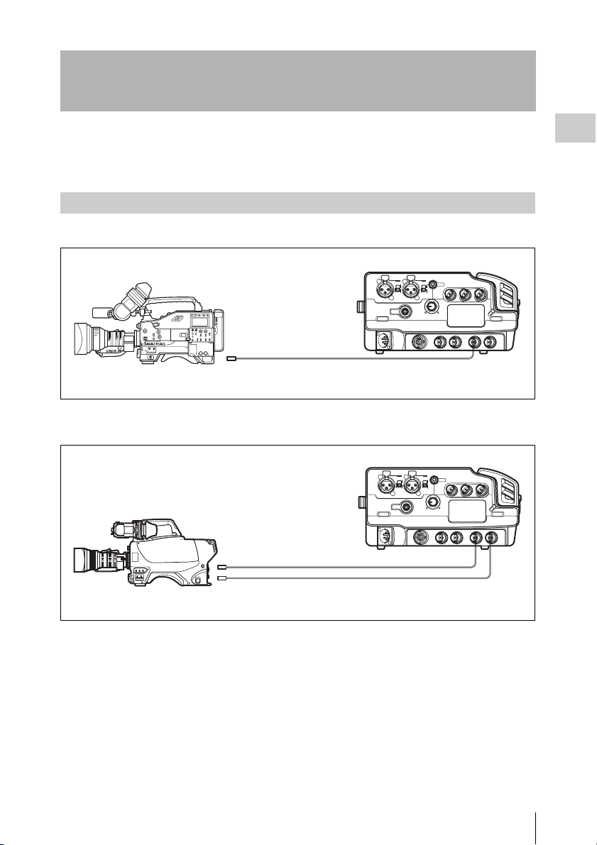
Connecting a Camera/Camcorder
Using the HDW-F900R or similar to record a 4:2:2 signal
SR-R1
HD SDI OUT
HD SDI IN A
HDW-F900R HD Camcorder
Using the HDC1500R to record an RGB 4:4:4 or 4:2:2 50p/59p signal
SR-R1
Chapter 2 Preparation
LINK A/B OUT
HDC1500R Multi-Format Camera System
HD SDI IN A
HD SDI IN B
Connect HD SDI Compliant Equipment
19
Page 20

Connecting an HD Monitor
HD monitor
Chapter 2 Preparation
SR-R1
HD SDI OUT (MON) 1
Connecting a RGB4:4:4 and 1080 50p/60p (Dual Link) compatible HD monitor
SR-R1
LINK B IN LINK A IN
HD SDI OUT (MON) 2
HD SDI OUT (MON) 1
HD video input
HD SDI
BVM-E250 HD Monitor
Connect HD SDI Compliant Equipment
20
Page 21

About the Reference Sync Signal
External synchronization required
If external synchronization is required, connect an HD SDI signal synchronized to the reference signal.
Recording/playback with synchronized camera, switcher, signal generator etc.
Reference signal
Chapter 2 Preparation
SR-R1
REF IN, GENLOCK IN
HD SDI IN A/B
(A only, or A/B)
Tip
If no external synchronization source is available, internal sync will be used.
Camera, switcher, signal
generator etc.
HD SDI OUT
(MON) 1/2
(1 only, or 1/2)
Connect HD SDI Compliant Equipment
21
Page 22

Turn Power On
• The voltage shown is the actual voltage used by the
unit (this may be lower than the input voltage and the
DC IN connector).
When a battery pack is selected
The battery symbol is shown.
Chapter 2 Preparation
To power up the unit
1 When using the AC adapter, turn
power to the AC adapter on.
2 Press the power switch on the SR-R1 on
the ? side.
Power comes on and the POWER indicator
lights up in green.
To power down the unit
1 Press the power switch on the SR-R1 on
the 1 side.
Power is turned off and the POWER
indicator goes out.
2 When using the AC adapter, turn
power to the AC adapter off.
Note
To prevent the risk of data corruption, do not interrupt
the DC IN power supply while the SR-R1 is turned on.
Tip
If power is turned off while an SRMemory card is
mounted, the unit will not power down immediately, to
protect the data on the card. The SRMemory card will be
unmounted first, and then the unit powers down.
16.5V
• When fully charged, all seven segments are lit.
As the battery pack discharges, the segments go
out from left to right.
• When the battery pack is almost exhausted
(NEAR END), the voltage indication and the
tally indicator start to flash, and an intermittent
warning tone sounds in the earphones.
• When the battery pack is completely exhausted
(END), the corresponding warning indication
lights, the tally indicator starts to flash at a
higher rate, and the earphones warning tone
sounds continuously.
Tip
The DCIN TYPE option in the SYSTEM Setup menu
allows you to set the battery voltages which trigger the
NEAR END and END warnings. (see page 48)
When AC power is selected
The connector symbol is shown.
16.5V
Checking the power/voltage
The indication at the bottom left of the control
panel display serves to verify the battery status or
the voltage of the external power supply.
However, this indication is not based on the
actual connection condition but on the setting
made under SYSTEM Setup > BATTERY >
DCIN TYPE. (see page 48)
Set DCIN TYPE to match the pow er supply being
used.
Tips
• When signal format and SR Motion are shown, the
indication appears at bottom right.
Turn Power On
22
Page 23

Insert SRMemory Card
Supported SRMemory cards
The SR-R1 can use the following types of
SRMemory cards.
For 59.94i
SRMemory card SR-Lite SR-SQ
SR-256S15/256S55 114 60
SR-512S25/512S55 228 120
SR-1TS25 457 241
Unit: minutes (approx.)
For 50i
SRMemory card SR-Lite SR-SQ
SR-256S15/256S55 137 72
SR-512S25/512S55 274 145
SR-1TS25 549 290
Unit: minutes (approx.)
For 23.98P
SRMemory card SR-Lite SR-SQ
SR-256S15/256S55 142 77
SR-512S25/512S55 285 155
SR-1TS25 572 311
Unit: minutes (approx.)
1) Recording times will differ depending on equipment
and shooting conditions.
Inserting and Removing the SRMemory Card
To insert the SRMemory card
SRMemory card
Tip
If the LID LOCK indicator is lit in orange, showing
that the lid is locked, press the EJECT button on the
control panel to unmount the card first, and then
open the lid.
2 Push the SRMemory card all the way in
and close the lid.
The SRMemory card is mounted, and the
LID LOCK indicator lights up in orange.
Verify that no error message is shown on the
control panel display.
If a message prompting you to salvage or format
the SRMemory card appears on the display
This indicates that the previous recording did not
complete normally.
For information on what to do in this case, see
“Salvaging SRMemory cards for which recording
did not complete properly” (page 54) in the
“Troubleshooting” section.
Chapter 2 Preparation
1 Press the lid open/close button to open
the lid of the SRMemory card slot and
insert the SRMemory card.
Take care to insert the SRMemory card with
the correct orientation.
Insert SRMemory Card
23
Page 24

To remove the SRMemory card
1 Press the EJECT button on the control
panel while power to the unit is on.
The files in the SRMemory card are closed
automatically, the SRMemory card is
Chapter 2 Preparation
unmounted, and the lock of the lid is
released.
During the unmount procedure, the indicator
of the EJECT button on the control panel is
lit.
2 Press the lid open/close button to open
the lid.
3 Press the EJECT button on the right
side of the slot to remove the
SRMemory card.
Formatting an SRMemory Card (File System Format )
SRMemory cards are sold already formatted, so
you can use a newly purchased SRMemory card
right away.
To format an SRMemory card on which data were
recorded, proceed as follows.
Note
Formatting will erase all files and data on the SRMemory
card.
For details on menu operation, see “Basic Menu
Operations” (page 25).
1 Press the SYSTEM button.
The SYSTEM Setup menu appears.
2 Select and confirm “SRMemory” t
select and confirm “FORMAT” t
move the cursor to [OK] and confirm
while pressing the FUNC button.
The file system formatting process starts.
When the process is finished, the indication
“Completed” is shown.
Pressing this button causes the SRMemory
card to pop out.
Write-protecting the card
In order to prevent inadvertent erasure of
recorded content, you can slide the write protect
switch to “WP.”
Write protect switch Slide
fully to the right.
When the card is inserted in the SR-R1 in this
condition, the indication “REC INHI” appears,
and recording is not possible.
To re-enable recording on this card, return the
write protect switch to the original condition.
Insert SRMemory Card
24
3 Return to the HOME screen. (see
page 26)
Page 25

Chapter 3 Basic Menu Operations
The menu system of the SR-R1 consists of the
following four menus.
Menu Overview
TC Setup Serves for making time code
settings.
AUDIO Setup Serves for making audio signal
related settings.
SYSTEM Setup Serves for making system
settings.
For details on menu items, see “Menu Details”
(page 41).
The menu is operated with the control panel.
Buttons Used for Menu Operations
HOME button SELECT/ENTER dial
BACK button
TC Setup
TIMER SEL
HOME
TC
VIDEO
AUDIO
SYSTEM
TIMER RESET
TIMER PRESET
TCR SEL
TCG MODE
REGEN SRC
RUN MODE
TCG SET
OTHERS
CHAR
TC
LTC
PRST
INT L
R RUN
SR-R1
TCR
Menu selection buttons
KEY INHI
OFF ON
LIGHT
OFF ON
EJECT STOP PLAY
FUNC
00:00:00:00STOP
ADJUST
xZzB
REW F FWD PAUSE
mXM
SELECT/ENTER
REC
BACK
Serve for Selecting a Menu
Selecting a menu
Press the respective menu selection button.
TC: Brings up the TC Setup menu.
AUDIO: Brings up the AUDIO Setup menu.
SYSTEM: Brings up the SYSTEM Setup menu.
Selecting and making settings within a
menu
Example: TC Setup menu
1 Rotate the SELECT/ENTER dial to
move the cursor to the target item, and
press the SELECT/ENTER dial.
TC Setup
TIMER SEL
TIMER RESET
TIMER PRESET
TCR SEL
TCG MODE
REGEN SRC
RUN MODE
TCG SET
OTHERS
CHAR
SR-R1
TC
LTC
PRST
INT L
R RUN
TCR
00:00:00:00STOP
Chapter 3 Basic Menu Operations
Cursor
A submenu for the selected item appears, and
the cursor moves to the submenu.
If the selected item is a command, the
command is executed.
25
Page 26

2 Rotate the SELECT/ENTER dial to
move the cursor to the target item, and
press the SELECT/ENTER dial.
Submenu window
TC Setup
TIMER SEL
TIMER RESET
TIMER PRESET
TCR SEL
TCG MODE
REGEN SRC
RUN MODE
TCG SET
OTHERS
CHAR
TC
LTC
PRST
INT L
R RUN
DF/NDF
UBG SRC
12H/24H
Chapter 3 Basic Menu Operations
SR-R1
A setting window appears, and the cursor
moves to the setting window.
3 Rotate the SELECT/ENTER dial to
select the desired setting, and press the
SELECT/ENTER dial to accept the
setting.
Setting window
TC Setup
TIMER SEL
TIMER RESET
TIMER PRESET
TCR SEL
TCG MODE
REGEN SRC
RUN MODE
TCG SET
OTHERS
CHAR
TC
LTC
PRST
INT L
R RUN
DF/NDF
UBG SRC
12H/24H
TCG Setting(Main)
TCR
00:00:00:00STOP
TCG Setting(Main)
12H/24H MODE
+/-12H
24H
DF
TCG
24H
DF
TCG
24H
Locking the Controls
To prevent operation errors or an inadvertent
change in settings, the controls of the unit can be
locked.
Access the SYSTEM Setup menu and set KEY
INHI to “ALL” (see page 47), and then slide the
KEY INHI switch to ON.
KEY INHI switch
SDI
SDI
SDI
SDI
SDI
SDI
SDI
SDI
SDI
SDI
SDI
SDI
SDI
SDI
SDI
dB
0
-10
HOME
-20
-30
-60
EMP
EMP
EMP
EMP
EMP
EMP
EE
TC
LR
LR
LR
LR
LR
LR
1
2
3
4
5
VIDEO
AUDIO
SYSTEM
6
STOP
TCG
00H00M00S00
16.5V
REMAIN
10min
ON: All controls of the unit are inactive.
OFF: During recording, the STOP and PAUSE keys
are active, and all other controls are inactive.
(When not recording, all controls of the unit are
inactive.)
Tip
When KEY INHI in the SYSTEM Setup menu is
set to “Map”, the “KEYMAP” settings apply. (see
page 47)
SDI
KEY INHI
EMP
EMP
EMP
LR
LR
L R
7
8
9
ENCODE
SR-SQ
10bit
OFF ON
EMP
EMP
EMP
EMP
EMP
EMP
EMP
LR
L R
10
11
1920x1080
59.94I
4:2:2
LIGHT
L R
L R
L R
LR
LR
12
13
14
15
16
OFF ON
SR-R1
KEY
INHI
RECINHI
EJECT STOP PLAY
F
LOCAL
FUNC
EE
21:46
ADJUST
xZzB
REW F FWD PAUSE
mXM
SELECT/ENTER
REC
BACK
SR-R1
To return to an upper level
Press the BACK button.
To return to the HOME screen
Press the HOME button or press the BACK
button repeatedly.
26
TCR
00:00:00:00STOP
Page 27

Signal Format Settings
Selecting the Signal Format
SYSTEM Setup
FILE LIST
SIGNAL FORMAT
TEST SG
LCD
KEY MAP
KEY INHI MAP
REC INHI OFF
POWER
BATTERY
SRMemory
OTHERS
SET
Signal Format
FRAME 29.97
SIGNAL 422
SELECT FPS OFF
FPS FORMAT 23/24
ENCODE
[SET]
SR-Lite
Making “SIGNAL FORMAT” settings
1 Press the SYSTEM button.
The SYSTEM Setup menu appears.
2 1 Select “SIGNAL FORMAT”, and
confirm t2 select “RES”
(Resolution) , and confirm t3 select
the format to use, and confirm.
1 SIGNAL FORMAT
2 RES
SYSTEM Setup
FILE LIST
SIGNAL FORMAT
TEST SG
LCD
KEY MAP
KEY INHI MAP
REC INHI OFF
POWER
BATTERY
SRMemory
OTHERS
SR-R1
Signal Format
RES
1920x1080I
FRAME
SIGNAL
SELECT FPS
FPS FORMAT 23/24
1920x1080PsF/P
TCR
Resolution
1920x1080I
00:00:00:00STOP
SR-LiteENCODE
29.97
422
OFF
3 Signal format
Return to submenu window.
3 Make settings for FRAME, SIGNAL,
and ENCODE in the same way.
SR-R1
TCR
00:00:00:00STOP
The settings complete message is shown, and
the HOME screen appears again.
Chapter 3 Basic Menu Operations
4 After settings are complete, select SET.
Signal Format Settings
27
Page 28

Display Settings
Date Settings
You can make settings for backlight use in dark
locations, screen saver, etc.
Using the Backlight
Chapter 3 Basic Menu Operations
Setting the LIGHT switch to ON turns the
backlight on.
LIGHT switch
SDI
SDI
SDI
SDI
SDI
SDI
SDI
SDI
SDI
SDI
SDI
SDI
SDI
SDI
SDI
dB
0
-10
HOME
-20
-30
-60
EMP
EMP
EMP
EMP
EMP
EMP
EE
TC
LR
LR
LR
LR
LR
LR
1
2
3
4
5
VIDEO
AUDIO
SYSTEM
6
STOP
TCG
00H00M00S00
16.5V
REMAIN
10min
Adjusting the backlight brightness
Access the SYSTEM Setup menu and select LCD
> BRIGHT (see page 47). The Backlight
Brightness window appears, letting you adjust the
setting.
Turning the backlight off after a period of
inactivity
Access the SYSTEM Setup and select LCD >
LIGHT OFF (see page 47). The Backlight Off
Timer window appears, letting you adjust the
backlight activation duration. The setting range is
5 seconds to 5 minutes. To disable automatic
backlight deactivation, select “Disable.”
Default setting: Disable
SDI
KEY INHI
EMP
EMP
EMP
LR
LR
L R
7
8
9
ENCODE
SR-SQ
10bit
OFF ON
EMP
EMP
EMP
EMP
EMP
EMP
EMP
LR
L R
10
11
1920x1080
59.94I
4:2:2
LIGHT
L R
L R
L R
LR
LR
12
13
14
15
16
OFF ON
SR-R1
KEY
INHI
RECINHI
EJECT STOP PLAY
xZzB
F
LOCAL
EE
21:46
FUNC
REW F FWD PAUSE
mXM
Display the System menu and select OTHERS
>SET DATE menu to set the date and time of the
unit.
To set the date and time (OTHERS >SET
DATE menu)
1 Display the System menu, and then
select and confirm “OTHERS” t
select and confirm “SET DATE.”
SELECT/ENTER
BACK
ADJUST
REC
2 Set the year, month, day, local time, and
UTC (Coordinated Universal Time)
offset (e.g., +9:00 for Japan), and then
select and confirm [SET].
Note
Time information is recorded to SRMemory cards in
UTC format and is displayed using the offset value as its
base.
Using the Screen Saver
Access the SYSTEM Setup menu and select LCD
>SAVER (see page 47). The Screen Saver
window appears, letting you adjust the wait
interval until the screen saver is activated. The
setting range is 1 minute to 1 hour. To disable the
screen saver, select “Disable.”
Default setting: Disable
Display Settings / Date Settings
28
Page 29

Chapter 4 Recording and Playback
Preparation Operation Reference
Recording Preparations and Operations
Before recording, make the following
preparations.
Set time code
generator
operation in
accordance with
the time code and
user bits to record.
Configure the other related menu settings as
necessary.
RUN MODE,
TCG MODE, and
REGENE
SOURCE in the
TC Setup
menu
page 32
Recording preparations
Preparation Operation Reference
Set the date and
time for the unit.
Select the format
signals to record.
Select the audio
signals to record.
Set the audio
signals to monitor.
Set the display
range of the audio
level meters.
Set the recording
levels.
Adjust the levels
of audio signals
output via the
EARPHONES
jack.
Cancel record
inhibit if the
system is set to
record inhibit
mode.
Select the time
data to display.
OTHERS >SET
DATE in the
SYSTEM Setup
menu
SIGNAL
FORMAT in the
SYSTEM Setup
menu
INPUT SEL in the
AUDIO Setup
menu
PHONE SEL in
the AUDIO Setup
menu
METER TYPE in
the AUDIO Setup
menu
REC LEVEL in
the AUDIO Setup
menu
Rotate the LEVEL
knob of the
EARPHONES
jack.
REC INHI in the
SYSTEM Setup
menu
TIMER SEL in
the TC Setup
menu
page 28
page 27
page 29
page 30
page 30
page 31
page 10
page 33
page 31
Setting the Audio Signals
Use the AUDIO Setup menu to make settings
related to audio signals.
Press the AUDIO button to display the AUDIO
Setup menu.
To select the audio signals to record
Select the audio signal to record for each track.
1 Display the AUDIO Setup menu and
then 1 select and confirm “INPUT
SEL” t2 select and confirm the track
(TRACK1 to TRACK16) t3 select
and confirm the signal to record.
1 INPUT SEL
2 Track
AUDIO Setup
INPUT SEL
PHONE SEL
MIX MODE
REC LEVEL
PB LEVEL
METER TYPE
PEAK HOLD
BEEP(PHONE)
INPUT DELAY
SR-R1
RMS
PEAK
ON
0
AUX SDI1 to AUX SDI16: Digital audio
signals of the SDI signal input via the
AUX SDI connector
SDI1 to SDI16: SDI signals input via the HD
SDI IN connector A
INPUT Select
TRACK1
AUX SDI1
TRACK2
AUX SDI2
TRACK3
AUX SDI3
TRACK4 AUX SDI4
TCR
00:00:00:00STOP
3Signal to record
Chapter 4 Recording and Playback
Recording Preparations and Operations
29
Page 30

ANA1 to ANA2: Analog signals input via
the AUDIO INPUT CH-1 and CH-2
connectors
2 Set the signal to record for each of the
other tracks in the same way.
To set the audio signals to monitor
Set the audio monitor signal to output from the
EARPHONES jack for each channel.
1 Display the AUDIO Setup menu and
then select and confirm “PHONE
SEL.”
The Phone Select screen appears.
To set the mixing mode for audio signals
Display the AUDIO Setup menu and then
1 select and confirm “MIX MODE”
t2 select and confirm the mixing mode.
1 MIX MODE 2 Mixing mode
AUDIO Setup
INPUT SEL
PHONE SEL
MIX MODE
REC LEVEL
PB LEVEL
METER TYPE
PEAK HOLD
BEEP(PHONE)
INPUT DELAY
RMS
PEAK
ON
MIX MODE
AddAdd
RMSRMS
AverageAverage
2 1 Select and confirm the channel
Chapter 4 Recording and Playback
number (1 to 16) t2 press the
SELECT/ENTER dial to select the
channel L/R setting.
Each press of the SELECT/ENTER button
changes the channel L/R setting in the order
of “–L” t“–R ”t“LR ”t“– – .”
Move the cursor to and select this
Output audio indications
Phone Select
1 2 3 4 5 6 7 8 9 10 11 12 13 14 15 16
CH1 L CH2 - R
CH3 - CH4 - -
SR-R1
CH5 L CH6 - R
CH7 - CH8 - -
CH9 - CH10 - CH11 - CH12 - -
TCG
Channel numbers
Set “– –” if you do not want to output the
audio signal of the selected channel from the
EARPHONES jack, and “LR” if you want to
output the audio signal via both the left and
right.
3 Set each of the other channels in the
same way.
CH13 - CH14 - -
CH15 L CH16 - R
00:00:00:00STOP
END
L/R setting
SR-R1
TCR
00:00:00:00STOP
ADD: Simple addition
RMS: Geometric mean
Average: Simple average
Setting the Recording Levels
Use the AUDIO Setup menu to make settings
related to the recording levels.
Press the AUDIO button to display the AUDIO
Setup menu.
The recording levels can be checked with the
audio level meters displayed in the display on the
control panel. The audio level meter indications
automatically switch between the recording
levels for during recording and the playback
levels for during playback.
To set the display range of the audio
level meters
Display the AUDIO Setup menu and then
1 select and confirm “METER TYPE”
t2 select and confirm the scale setting method.
4 When you have finished making the
settings, move th e cursor to and confirm
“END.”
Recording Preparations and Operations
30
Page 31

1 METER TYPE
AUDIO Setup
INPUT SEL
PHONE SEL
MIX MODE
REC LEVEL
PB LEVEL
METER TYPE
PEAK HOLD
BEEP(PHONE)
INPUT DELAY
SR-R1
RMS
PEAK
ON
2 Scale setting
method
METER TYPE
PEAKPEAK
REFREF
FINEFINE
TCR
00:00:00:00STOP
Full Peak: Displays 0 dBFS as the peak value.
Full Ref: Displays the reference level (+4 dBu) as
0dB.
Fine: Displays a scale with 0.25 dB steps and the
reference level at the center.
To set the recording levels
The recording level can be set for each channel.
Note
The recording levels cannot be set during
playback.
1 Display the AUDIO Setup menu and
then select and confirm “REC
LEVEL.”
The Rec Level screen appears.
2 Select and confirm the channel number
(1 to 16).
When a channel is selected, the current
recording level is indicated by a hexadecimal
number. “UNI” is indicated for a channel
whose recording level has not been changed.
3 Move the cursor to and confirm “VAR”
t use the ADJUST knob to set and
confirm the recording level.
Rotate the knob clockwise to increase the
level, and counterclockwise to decrease the
level.
To reset the setting
Rotate the SELECT/ENTER dial to move the
cursor to RESET, and then press the dial.
When you want to change the setting
Move the cursor to and confirm “UNI.”
Move the cursor to and select this
Recording levels
Rec Level
1 2 3 4 5 6 7 8 9 10 11 12 13 14 15 16
CH1 4040
CH2 4040
CH3 UNI
CH4 UNI
Channel numbers
SR-R1
CH5 4040
CH6 4040
CH7 4040
CH8 4040
CH9 UNI
CH10 UNI
CH11 UNI
CH12 UNI
UNI/VAR
TCG
CH13 4000
CH14 4000
CH15 4000
CH16 4000
RESET
00:00:00:00STOP
END
Recording level settings
4 Set the recording level of each of the
other channels in the same way.
5 When you have finished making the
settings, mo ve the cursor to and co nfirm
“END.”
Setting the Time Code and User Bits
Use the TC Setup menu to make settings related
to audio signals.
Press the TC button to display the TC Setup
menu.
To select the time data to display
Display the TC Setup menu and then 1 select
and confirm “TIMER SEL” t2 select and
confirm the time data you want to display.
1 TIMER SEL
2 Time data
TC Setup
TIMER SEL
TIMER RESET
TIMER PRESET
TCR SEL
TCG MODE
REGENE SOURCE
RUN MODE
TCG SET
OTHERS
CHAR
SR-R1
TC: Displays the time code.
UBIT: Displays the user bits.
TC
LTC
PRST
INT L
R RUN
TIMER Mode Select
TCTC
UBITUBIT
TM1TM1
TM2TM2
TCR
00:00:00:00STOP
Chapter 4 Recording and Playback
Recording Preparations and Operations
31
Page 32

TM1/TM2: Displays the timer value of Timer 1 or
Timer 2.
To select the time code to record
The time code can be selected in the following menu.
Menu item Time code
TCG MODE REGENE SOURCE
PRST — An arbitrary time code can be set. (R RUN/F RUN and DF/NDF can
RGN EXT L In accordance with the time code input via the TC IN connector.
SDI L In accordance with the LTC time code of the video signal input via
SDI V In accordance with the VITC time code of the video signal input via
be set to an arbitrary value in the menu.)
the HD SDI IN A/B connector.
the HD SDI IN A/B connector.
To select the user bits to record
The user bits can be selected in the following menu.
Chapter 4 Recording and Playback
Menu item User bits
TCG SET >
UBG
SOURCE
TCG PRST Arbitrary user bits can be set. (TIMER PRESET > TCG UBIT)
INT — Arbitrary user bits can be set regardless of the setting of TCG
TCG MODE
RGN In accordance with the user bit value of the time code selected for
REGEN SOURCE.
MODE. (TIMER PRESET > TCG UBIT)
Recording Preparations and Operations
32
Page 33

To record the time code
The following methods are available for
recording the time code.
• Set the initial value and record the time code.
• Externally synchronize the internal time code
generator.
To set the initial value and record the time code
Set an arbitrary initial value and then record the
output of the internal time code generator.
1 Display the TC Setup menu and then
1 select and confirm “TIMER
PRESET” t2 select and confirm
“TCG TC” t3 move the cursor to
and confirm the digit of the value you
want to change t4 rotate the
SELECT/ENTER dial to change the
value and then confirm the value.
Set the other digits as necessary.
1 TIMER
PRESET
TC Setup
TIMER SEL
TIMER RESET
TIMER PRESET
TCR SEL
TCG MODE
REGENE SOURCE
RUN MODE
TCG SET
OTHERS
CHAR
SR-R1
4Rotate the dial to change the value
TC
LTC
PRST
INT L
R RUN
3 Cursor
2 TCG TC
TCG TC
TCG UB
TM1
00 30 00 00
TCR
TIMER Preset
TCG TC
SET
00:00:00:00STOP
2 When you have finished making the
settings, move th e cursor to and confirm
“SET.”
If “RUN MODE” is set to “F RUN,” the time
code starts advancing immediately.
To set all digits to 0
Select and confirm TC Setup > TIMER RESET to
return all values to 0.
To externally synchronize the internal time code
generator
Record the output of the internal time code
generator synchronized to the time code of an
external input.
Use the following method to synchronize the time
code generators of multiple VTRs.
Display the TC Setup menu and then set “TCG
MODE” to “RGN” and select the signal for the
time code generator to regenerate in “REGENE
SOURCE.”
For details, see “To select the time code to record”
(page 32).
To record the user bits
By setting user bits, you can record up to eight
hexadecimal digits of information (date, time,
etc.).
To set an arbitrary value and then record user
bits
1 Set the TC Setup menu.
To set arbitrary user bits regardless of the
setting of “TCG MODE,” set TCG SET >
UBG SOURCE to “INT.” If “TCG MODE”
is set to “PRST,” TCG SET(MAIN) > UBG
SOURCE can be set to any value.
For details, see “To select the time code to
record” (page 32).
2 Set the user bits using the same
procedure as “To set the initial value and
record the time code” (page 33).
Tip
As with the time code, all digits can be returned to 0 with
“TIMER RESET.”
Recording
1 Check that the REC INHI indicator is
off and then insert an SRMemory card.
Before you insert the SRMemory card, check
that its write-protect switch is not set to
“WP.”
For details, see “To insert the SRMemory card”
(page 23) and “Write-protecting the card”
(page 24).br
When the REC INHI indicator is lit
Record inhibit is set.
• Set SYSTEM Setup > REC INHI to “OFF.”
(see page 47)
• Check that FS LOCK for the SRMemory
card is not locked. (see page 48)
Chapter 4 Recording and Playback
Recording Preparations and Operations
33
Page 34

• Check that the write-protect switch for the
SRMemory card is not in the WP position.
2 Press the PLAY button while holding
down the REC button.
Recording starts, and “REC LOCK” appears.
3 Press the STOP button to stop
recording.
Chapter 4 Recording and Playback
Playback Preparations and Operations
Making Settings Related to Audio Monitor Signals
The AUDIO Setup menu allows you to make
various settings related to audio monitor signals
for playback. The setting procedures are the same
as for recording.
For details, see “Setting the Audio Signals”
(page 29) and “AUDIO Setup Menu” (page 44).
To adjust the level of audio output via the
EARPHONES jack
Rotate the LEVEL knob.
Adjusting Playback Audio Levels
The playback audio level can be set for each
channel in “PB LEVEL” of the AUDIO Setup
menu.
The setting procedure is the same as in steps 2 and
3 of “To set the recording levels” (page 31).
Note
The playback audio level cannot be adjusted during
recording.
To set the display range of the audio level meters
See “To set the display range of the audio level
meters” (page 30) for during recording.
Playback Preparations and Operations
34
Selecting the Time Data to Display During Playback
Display the TC Setup menu and then select the
time data you want to display in “TIMER SEL.”
TC: Displays the LTC or VITC.
Select which one is displayed in “TCR SEL” in
the TC Setup menu.
UBIT: Displays the user bits for the time code
selected in “TCR SEL” in the TC Setup menu.
TM1/TM2: The values counted in accordance with
the playback frames.
(With TM2, the beginning of the file is 0 and the
value cannot be reset.)
Page 35

Playback
1 Insert the SRMemory card to play
back.
For details, see “ To insert the SRMemory card”
(page 23).
2 Press the PLAY button.
Playback starts and the PLAY LOCK
indication lights up.
3 Press the STOP button when you want
to stop playback.
Chapter 4 Recording and Playback
Playback Preparations and Operations
35
Page 36

How to Use the Recording and Playback Operation Buttons
Button Function when pressed alone Function when pressed with FUNC
STOP button Stops the recording and playback
PLAY button and indicator Starts playback. (The indicator is lit
REC button and indicator To start recording, press the PLAY
Chapter 4 Recording and Playback
REW button and indicator Moves to the beginning of the current
F FWD button and indicator Moves to the beginning of the next
PAUSE button and indicator Pauses playback. (The indicator
operation.
during playback.)
To start recording, press this button
while holding down the REC button.
To move to the last frame of the
currently playing file, press this
button while holding down the F
FWD button.
button while holding down this
button. (The indicator is lit during
recording.)
file.
If this button is pressed when at the
beginning of the file, moves to the
beginning of the previous file.
file.
flashes during pause.)
Pressing this button again resumes
playback.
butto n
—
—
—
Executes a reverse direction search.
With each press, the search speed
changes in the order of x2 t x5 t x8
t x16 t x32 t x2 ...
If a search is interrupted by another
operation, the next search is performed
at the speed in effect at the time of the
interruption.
Executes a forward direction search.
With each press, the search speed
changes in the order of x2 t x5 t x8
t x16 t x32 t x2 ...
If a search is interrupted by another
operation, the next search is performed
at the speed in effect at the time of the
interruption.
—
How to Use the Recording and Playback Operation Buttons
36
Page 37

Making Superimpose
1
37654
Settings
Time codes, operating modes, warning/error
messages, and other text information can be
superimposed on (added to) the video signals
output from the HD SDI OUT (MON)
connectors.
Superimposed information displayed
Time data
TCR.12:34.56.01*
PLAY LOCK
R123min 13.8V
2
“PLAY PAUSE”
“F.FWD”
“REW”
“UNMOUNT”
“STOP”
c Remain ing amount of recording tim e on
SRMemory card
d Drop frame mark of the time code
reader
“ . ”: When drop frame mode
“ : ”: When non-drop frame mode
e Drop frame mark of the time code
generator
“ . ”: When drop frame mode
“ : ”: When non-drop frame mode
f VITC field mark
“ ” (blank): When odd field displayed
“*”: When even field displayed
Chapter 4 Recording and Playback
a Time data types
Symbol Meaning
TM1 Data of TM1 counter
TM2 Data of TM2 counter
TCR Time code data of LTC reader
UBR User bit data of LTC reader
TCR. Time code data of VITC reader
UBR. User bit data of VITC reader
TCG Time code data of time code generator
UBG User bit data of time code generator
b Operation mode
The information is divided into blocks A and B
and displayed as shown below.
Block A: Operating mode
Block B: Mode lock state or playback speed
AB
There are the following operating mode
indications.
“SYSTEM READY”
“REC”
“REC LOCK”
“PLAY”
“PLAY LOCK”
g Battery voltage
Indicates the voltage of the battery or AC power
supply.
To display warning/error messages
1 Set CHAR >MODE in the TC Setup
menu to other than “TIME.”
2 Set “WARN” to “W+E” to display both
warning messages and error messages,
and set it to “ERR” to display only error
messages.
The first 16 characters of a message flash on
the second line.
TCR.23:59:40:18
NO SDI I NPUT A
First 16 characters of a warning/error
message
For details, see “Error Messages and Warning
Messages” (page 52).
When there are multiple warning/error
messages at the same time, a message flashes
twice in succession and then is replaced by
the next message.
Making Superimpose Settings
37
Page 38

When a warning/error message is not being
displayed, the information selected in CHAR
> MODE in the TC Setup menu flashes on
the second line.
To change the superimpose position
The superimpose position can be moved to 16
different positions in the horizontal direction (0 to
15) and 24 different positions in the vertical
direction (0 to 23).
Set the position in CHAR > HPOS/VPOS in the
TC Setup menu.
Chapter 4 Recording and Playback
FILE LIST Operations
“FILE LIST” in the SYSTEM Setup menu allows
you to perform operati ons such as displaying a list
of the files recorded to the SRMemory card,
displaying detailed information, performing file
operations (deleting and renaming), and playing
back files.
Displaying a File List
1 Display the SYSTEM Setup menu and
then 1 select and confirm “FILE
LIST” t2 select and confirm “FILE
LIST.”
1 FILE LIST 2 FILE LIST
SYSTEM Setup
FILE LIST
SIGNAL FORMAT
TEST SG
LCD
KEY MAP
KEY INHI MAP
REC INHI OFF
POWER
BATTERY
SRMemory
OTHERS
Signal Format
FILE LIST
SORT Data
FILE LIST Operations
38
SR-R1
The File list window appears.
TCR
00:00:00:00STOP
Page 39

Displayed information
a Icon b File list
c Cusor
File list
<\>
[File Name] [Date] [Duration]
FILE00000001 ,10 JAN 2011 ,00:00:17
FILE00000002 ,10 JAN 2011 ,00:00:04
FILE00000003 ,10 JAN 2011 ,00:00:03
FILE00000004 ,10 JAN 2011 ,00:00:03
FILE00000005 ,10 JAN 2011 ,00:00:56
FILE00000006 ,10 JAN 2011 ,00:00:04
FILE00000007 ,10 JAN 2011 ,00:00:05
File Name: FILE00000007
Date: 10 JAN 2011 12:00:00:02
Duration: 00:00:03:22 VideoSize: 00160800
Format: 1920x1080 23PsF 444
SR-SQ 10bit
SR-R1
TCG
d Detailed information
a Icons
An icon indicates the current file state.
White: Stopped
Green: Playing
Red: Recording
b File list
A list of files recorded to the SRMemory card is
displayed.
The files that cannot currently be played by the
system are displayed in gray.
The icon of a file that is recording is displayed in
red, and the icon of a file that is playing is
displayed in green (current file).
c Cursor
Used for selecting files.
d Detailed information
The detailed information for the file at the cursor
position is displayed.
File Name: File name
Date: Recording date and time
Duration: Number of frames in file
Format: Recording data format type
[4/7]
00:00:00:00STOP
Display when the SRMemory card contains no
files
File list
<\>
No file data
Name: ------------------------
Date: -- --- ---- --: --: --: -DUR: --:--:--:-- VideoSize: -------Format: --------------------
SR-R1
TCG
[0/0]
00:00:00:00STOP
Display during recording
When recording starts, a new file with a red icon
to indicate recording is in progress is added to the
list. When recording stops, the icon turns white
(current file).
To select a file to play back
If you use the SELECT/ENTER dial to select and
confirm the file you want to play back, the icon
moves, the file opens.
Performing File Operations
Files can be renamed and deleted.
1 Select a file and then press the SELECT/
ENTER dial while holding down the FUNC
button to confirm the selection t 2 select and
confirm the desired operation.
1Select a file
File list
<\>
[File Name] [Date] [Duration]
FILE00000001 ,10 JAN 2011 ,00:00:17
FILE00000002 ,10 JAN 2011 ,00:00:04
FILE00000003 ,10 JAN 2011 ,00:00:03
FILE00000004 ,10 JAN 2011 ,00:00:03
FILE00000005 ,10 JAN 2011 ,00:00:56
FILE00000006 ,10 JAN 2011 ,00:00:04
FILE00000007 ,10 JAN 2011 ,00:00:05
PROTECT
Select Function
SR-R1
ALL DEL
MOVERENAME COPY
DELETE
TCG
[4/7]
MKDIR
00:00:00:00STOP
Chapter 4 Recording and Playback
2Select the operation
RENAME: Renames the file.
DELETE: Deletes the file.
PROTECT: Changes the file protection setting.
ALL DEL: Deletes all files.
FILE LIST Operations
39
Page 40

To rename a file
Select and confirm RENAME to display the file
rename screen.
Rename the file and then move the cursor to and
confirm [END] to apply the file name.
To cancel the change
Press the BACK button to return to the File list
screen.
To delete a file
Select and confirm DELETE to display the
confirmation screen.
Select [OK] and then press the SELECT/ENTER
dial while holding down the FUNC button to
confirm the selection and delete the file.
To cancel the deletion, select and confirm
[CANCEL] or press the BACK button to return to
Chapter 4 Recording and Playback
the file list.
Changing the File Display Order
The display order of files in the file list can be
changed.
1 Select and confirm [SORT] t2 select and
confirm the sort method.
1 SORT
SYSTEM Setup
FILE LIST
SIGNAL FORMAT
TEST SG
LCD
KEY MAP
KEY INHI MAP
REC INHI OFF
POWER
BATTERY
SRMemory
OTHERS
File List
FILE LIST
SORT Data
SR-R1
TCR
DATA: Displays the files in date order.
NAME: Displays the files in file name order.
DURATION: Displays the files in recording
time order.
FILE LIST Operations
40
00:00:00:00STOP
2Sort method
Page 41

Chapter 5 Menu Details
• The settings displayed in bold are the factory default settings.
• The settings enclosed in [] are the settings as displayed in the settings windows.
TC Setup Menu
Setting Item Settings
TIMER SEL Selects the type of time data to display on the display.
TC [Time Code]: Displays the time code: Displays the
time code.
UBIT [User Bit]: Displays the user bits.
TM1 [TIMER1]: Displays the file playback position in
Hours:Minutes:Seconds:Frames format.
TM2 [TIMER2]: Displays the playback position in
Hours:Minutes:Seconds:Frames format and treats the
beginning of the file as 0.
• TIMER RESET/PRESET are not available.
TIMER RESET Resets the internal time code generator, and the time data
becomes “00:00:00:00” (time code) or “00 00 00 00”
(user bits).
Notes
• The values read by the time code reader cannot be reset.
• Time data cannot be reset when the time code generator
is locked to external time codes or to values read by the
time code reader.
TIMER PRESET Selects the type of time data to preset to an arbitrary
valu e.
TCG TC: Time code generated by the time code generator
TCG UBIT: User bits generated by the time code
generator
TM1: TM1 signal count value
TCR SEL Selects the type of playback time code/user bits.
LTC [LTC]: Reads the LTC.
VITC [VITC]: Reads the VITC.
TCG MODE Selects the time code to which the internal time code
generator synchronizes.
PRST [Preset]: Allows you to use the “TIMER
PRESET” setting item to preset the initial value of the
time code generated by the internal time code
generator.
RGN [Regen]: Synchronizes the time generator to the
time code value selected in the following item
REGENE SOURCE (regenerate).
Chapter 5 Menu Details
TC Setup Menu
41
Page 42

Setting Item Settings
REGEN SRC Selects the time code to be synchronized (regenerated) by
RUN MODE Selects the run mode of the internal time code generator.
TCG SET
Time code generator
settings related to the
main time code
Chapter 5 Menu Details
OTHERS
Other settings related
to the main time code
DF/NDF
(Valid only when the frame
frequency of this system is
29.97 Hz.)
UBG SOURCE Selects the source time code of user bits.
12H/24H Selects the TIMER display mode.
TC OUT Selects the time code to output from the TC OUT
the internal time code generator.
EXT L [External LTC]: Time code input to the TC IN
connector
SDI L [SDI LTC]: LTC time data of video signal input to
the HD SDI IN connectors A
SDI V [SDI VITC]: VITC of video signal input to the HD
SDI IN connectors A
F RUN [Free Run]: Advances the time code while the
power is on.
R RUN [Rec Run]: Advances the time code only during
recording.
Sets the frame count mode.
DF [Drop Frm]: Drop frame mode
NDF [Non Drop Frm]: Non-drop frame mode
Note
This settings is valid only when TCG MODE is set to
“PRST.”
TCG [TCG Source]: Same source time code as that of the
time code generator
INT [Internal]: Time code generated by the time code
generator. Arbitrary user bits can be set regardless of
the setting of TCG (see page 33).
12H [+/–12H]: 12-hour display mode
24H [24H]: 24-hour display mode
Note
When +/–12H display is selected, the tens digit of the
hours value is dropped for values less than 10.
connector.
AUTO [Auto]: During playback, the time code read by
the internal time code reader. During recording or when
in E-E mode, the time code generated by the time code
generator.
TCG [TCG]: The time code generated by the time code
generator.
THRU [Through]: Outputs the time code input to the TC
IN connector as is.
42
TC Setup Menu
Page 43

Setting Item Settings
CHAR
Settings related to the
text information
superimposed on the
output from the HD
SDI OUT (MON)
connector
ON/OFF Sets whether or not to output text information.
ON [On]: Outputs.
OFF [Off]: Does not output.
HPOS Sets the display position of text information in the
horizontal direction.
0 to 15 (8)
VPOS Sets the display position of text information in the vertical
direction.
0 to 23 (21)
TYPE Selects the character type.
W/O [Without BG]: White characters with no
background.
OUTL [Outline]: White characters with black outlines.
TRNS [Translucent]: White characters on a gray screen
background.
BG [With BG]: White characters on a black background
SIZE Sets the size of text information.
x1 [x1]: Normal
x2 [x2]: Twice normal size
MODE Sets the content of text information.
+STAT [Time + Status]: Time counter display
information and status (operation status) information
+UB [Time + User Bit]: Time counter display information
and user bit data
+VITC [Time + VITC]: Time counter display information
and VITC
TIME [Time Only]: Time counter display information
only
+TM1 [Time + TM1]: Time counter display information
and TM1 counter value
+TM2 [Time + TM2]: Time counter display information
and TM2 counter value
Chapter 5 Menu Details
TC Setup Menu
43
Page 44

AUDIO Setup Menu
Setting Item Settings
INPUT SEL
Selection of input
signals
Chapter 5 Menu Details
PHONE SEL Selects the audio to output to the EARPHONES jack and
MIX MODE Selects the method of mixing the digital audio signals
TRACK1 Selects the signal to assign to track 1.
SDI1 [SDI CH1] to SDI16 [SDI CH16],
ANA1 [Analog CH1] to ANA2 [Analog CH2],
AUX1 [AUX SDI CH1] to AUX16 [AUX SDI CH16]
TRACK2 Selects the signal to assign to track 2.
Same settings as TRACK1 (SDI2)
TRACK3 Selects the signal to assign to track 3.
Same settings as TRACK1 (SDI3)
TRACK4 Selects the signal to assign to track 4.
Same settings as TRACK1 (SDI4)
TRACK5 Selects the signal to assign to track 5.
Same settings as TRACK1 (SDI5)
TRACK6 Selects the signal to assign to track 6.
Same settings as TRACK1 (SDI6)
TRACK7 Selects the signal to assign to track 7.
Same settings as TRACK1 (SDI7)
TRACK8 Selects the signal to assign to track 8.
Same settings as TRACK1 (SDI8)
TRACK9 Selects the signal to assign to track 9.
Same settings as TRACK1 (SDI9)
TRACK10 Selects the signal to assign to track 10.
Same settings as TRACK1 (SDI10)
TRACK11 Selects the signal to assign to track 11.
Same settings as TRACK1 (SDI11)
TRACK12 Selects the signal to assign to track 12.
Same settings as TRACK1 (SDI12)
TRACK13 Selects the signal to assign to track 13.
Same settings as TRACK1 (SDI13)
TRACK14 Selects the signal to assign to track 14.
Same settings as TRACK1 (SDI14)
TRACK15 Selects the signal to assign to track 15.
Same settings as TRACK1 (SDI15)
TRACK16 Selects the signal to assign to track 16.
Same settings as TRACK1 (SDI16)
RESET Restores all TRACK1 to TRACK16 items to their default
settings.
MONITOR OUT L and R connectors.
output to the EARPHONES jack.
ADD [Add]: Simple addition
RMS [RMS]: Geometric mean
AVG [Average]: Simple average
AUDIO Setup Menu
44
Page 45

Setting Item Settings
REC LEVEL Adjusts the recording level (see page 31). (This
PB LEVEL Adjusts the playback level (see page 34). (This
METER TYPE Sets the display range of the audio level meters.
PEAK HOLD Sets whether or not to use the peak hold function.
BEEP (PHONE)
Sets the volume of the
beep tone.
INPUT DELAY
Recording audio
signal phase setting
ALARM Sets whether or not to output alarm tones.
WARN Sets whether or not to output warning tones.
HDSDI Sets whether or not to add a delay to the HDSDI input
ANALOG Sets whether or not to add a delay to the ANALOG input
AUX IN Sets whether or not to add a delay to the AUX IN input
DELAY Sets the delay length for items set to be delayed.
adjustment is not possible during playback.)
adjustment is not possible during recording.)
PEAK [Full Peak]: Displays 0 dBFS as the peak value.
REF [Full Ref]: Displays the reference level (+4 dBu) as
0 dB.
FINE [Fine]: Displays a scale with 0.25 dB steps and -20
dB at the center.
ON [On]: Uses the function.
OFF [Off]: Does not use the function.
OFF [Off]: Does not output alarm tones.
HIGH [High]: Outputs high-level alarm tones.
LOW [Low]: Outputs low-level alarm tones.
OFF [Off]: Does not output warning tones.
HIGH [High]: Outputs high-level warning tones.
LOW [Low]: Outputs low-level warning tones.
audio.
[OFF]: Does not add delay.
ON [ON]: Adds delay.
audio.
[OFF]: Does not add delay.
ON [ON]: Adds delay.
audio.
[OFF]: Does not add delay.
ON [ON]: Adds delay.
0 [NO Delay]: Does not add delay.
+1 [+1F Delay]: Records the audio signal with a delay of
1 frame (use this when the input video signal has a
delay of one frame with respect to the audio signal).
+2 [+2F Delay]: Records the audio signal with a delay of
2 frames (use this when the input video signal has a
delay of two frames with respect to the audio signal).
+3 [+3F Delay]: Records the audio signal with a delay of
3 frames (use this when the input video signal has a
delay of three frames with respect to the audio signal).
+4 [+4F Delay]: Records the audio signal with a delay of
4 frames (use this when the input video signal has a
delay of four frames with respect to the audio signal).
+5 [+5F Delay]: Records the audio signal with a delay of
5 frames (use this when the input video signal has a
delay of five frames with respect to the audio signal).
Chapter 5 Menu Details
AUDIO Setup Menu
45
Page 46

SYSTEM Setup Menu
Setting Item Settings
FILE LIST FILE LIST Displays a list of recording files and allows recording files
SORT Sorts the files in the FILE LIST screen.
SIGNAL FORMAT
Settings of signal
formats
Chapter 5 Menu Details
TEST SG
Settings of test signal
output
Note
The VIDEO and
AUDIO settings are
both reset to “OFF”
(factory default
setting) when the
power is turned off.
RESOLUTION Sets the effective pixel count and scanning method.
FRAME Sets the operation frame frequency.
SIGNAL Sets the sampling format.
ENCODE Sets the video recording format and recording rate.
VIDEO Selects the test signal to generate with the internal video
AUDIO Selects the test signal to generate with the internal audio
to be selected and file operations to be performed.
For details, see “FILE LIST Operations” (page 38).
DATE: Date order
NAME: Name order
DURATION: Order of file recording length
1920 × 1080I [1920 × 1080I]
1920 × 1080P [1920 × 1080PsF/P]
23.98 [23.98]: Frame frequency of 23.976 Hz
24 [24]: Frame frequency of 24 Hz
25 [25]: Frame frequency of 25 Hz (field frequency of
50 Hz)
29.97 [29.97]: Frame frequency of 29.97 Hz (field
frequency of 59.94 Hz )
50 [50]: Frame frequency of 50 Hz
59.94 [59.94]: Frame frequency of 59.94 Hz
422 [4:2:2]: 4:2:2 (Y/Cb/Cr)
444 [4:4:4]: 4:4:4 (R/G/B)
SR-SQ, SR-Lite
For details, see “About Recording/Playback Formats”
(page 58).
signal generator.
OFF [Off]: Does not generate a test signal.
CB [Color Bar]: Color bar signal
SMPTE [SMPTE Color Bar]: SMPTE color bar signal
RP219 [RP-219 Color Bar]: RP-219 color bar signal
BLK [Black]: Black signal
signal generator.
OFF [Off]: Does not generate a test signal.
1KHz [1KHz Sine]: 1 kHz sine wave
NONE [Silence]: No sound
SYSTEM Setup Menu
46
Page 47

Setting Item Settings
LCD
Settings of display
backlight
KEYMAP
Settings of keymap
KEY INHI
Settings to inhibit button operation
REC INHI
Settings of recording inhibit mode
POWER
Settings to reduce
power consumption
by limiting output
signals or restricting
use of output
connectors
LIGHT OFF Sets whether or not to turn the backlight off after a set
BRIGHT Sets the backlight brightness.
SAVER Sets whether or not to use the screensaver after a set time.
SAVER MSG Sets the text information for the screensaver.
EJECT
EJECT button function
STOP
STOP button function
PLAY
PLAY button function
REC
REC button function
REW
REW button function
FFWD
FFWD button function
PAU SE
PAUSE button function
LED Controls the POWER indicator.
TALLY Controls the tally lamp.
time.
DIS [Disable]: Does not turn the backlight off.
5sec [5sec]: Turns the backlight off after 5 seconds.
10sec [10sec]: Turns the backlight off after 10 seconds.
30sec [30sec]: Turns the backlight off after 30 seconds.
1min [1min]: Turns the backlight off after 1 minute.
3min [3min]: Turns the backlight off after 3 minutes.
5min [5min]: Turns the backlight off after 5 minutes.
0 to 31 (20)
DIS [Disable]: Does not use the screensaver.
1min [1min]: Starts the screensaver after 1 minute.
3min [3min]: Starts the screensaver after 3 minutes.
5min [5min]: Starts the screensaver after 5 minutes.
10min [10min]: Starts the screensaver after 10 minutes.
20min [20min]: Starts the screensaver after 20 minutes.
30min [30min]: Starts the screensaver after 30 minutes.
1hour [1hour]: Starts the screensaver after 1 hour.
DIS [Disable]: Disables the button function.
ENA [Enable]: Enables the button function.
ALL [ALL]: Locks all.
MAP [MAP]: Locks only the buttons that are set to
“Disable” in the KEYMAP settings.
OFF [Off]: Does not prohibit recording.
ON [On]: Prohibits recording.
ON [On]: Lit normally
LOW [Low]: Dimly lit
OFF [Off]: Not lit
ON [On]: Lit normally
LOW [Low]: Dimly lit
OFF [Off]: Not lit
Chapter 5 Menu Details
SYSTEM Setup Menu
47
Page 48

Setting Item Settings
BATTERY
Settings related to the
remaining battery
power indication
SRMemory
SRMemory related
settings
Chapter 5 Menu Details
OTHERS SOFT VERSION Displays the version of each software installed on the unit.
DCIN TYPE Selects the type of battery to be connected to the DC IN
Near END
(DCIN)
END (DCIN) Sets the threshold voltage at which to show an end
INFO DISP Displays SRMemory card information.
FS LOCK Lock setting for the SRMemory card to disable file
FORMAT Formats the SRMemory card.
HOURS METER Display various count values using the digital hours meter
FORMAT LIST Displays a list of the available formats.
OPTION LIST Displays a list of installed options.
SET DATE Sets the date and time of the unit.
META DATA Sets 3-line metadata input.
REC TRIGGER Sets the recording start input trigger signal.
connector.
AC [AC Adapter]: AC adapter
Li-ion [Li-ion Battery]: Lithium ion battery
BP-GL [BP-GL Battery]: BP-GL95
OTH1 [ Ot he r 1]
OTH2 [ Ot he r 2]
Sets the threshold voltage at which to show a near-end
(almost exhausted)/warning indication for the battery
selected for the previous item “DCIN TYPE.”
11.0 to 15.0 (11.9 V)
(exhausted)/warning indication for the battery selected for
the item “DCIN TYPE.”
11.0 to 12.0 (11.0 V)
recording and playback.
LOCK: Locked.
UNLOCK: Unlocked.
Note
Formatting will erase all data recorded on the SRMemory
card.
(total since the start of use of the unit, or total during a
certain period).
SYSTEM: System operation time
LID LOCK: Number of lock plunger operations
For details, see “Date Settings” (page 28).
OFF [Off]: Recording is not triggered by an input signal.
SDI RMT [SDI REMOTE]: Recording is triggered by the
HDCAM’s SDI REMOTE signal.
SYNC [SYNC REC]: Recording is triggered by the
PMW-F3.
SYSTEM Setup Menu
48
Page 49

Appendix
Maintenance and Inspections
Note About the Power Supply Terminal
The power supply terminal of this unit (the
connector for the AC adapter) is a consumable
part.
Power may not be supplied to the unit properly if
the pins of the battery terminal are bent or
deformed by shock or vibrations, or if they
become corroded due to prolonged outdoor use.
Periodic inspections are recommended to keep
the unit working properly and to prolong its
usable lifetime. Contact a Sony service or sales
representative for more information about
inspections.
Specifications
General
Recording format
MPEG4 SStP format
Power supply
11 to 17 V DC
Power consumption
30 W (422 23.98PsF SR-Lite recording)
Operating temp erature
0 °C to 40 °C (32 °F to 104 °F)
Storage temperature
–20 °C to +60 °C
Operating relative humidity
10% to 95% (no condensation)
Mass
1.9 kg (4 lb. 2.9 oz.) (excl. SRMemory card and
control panel)
(–4 °F to +140 °F)
Appendix
Maintenance and Inspections / Specifications
49
Page 50

in.)
8
/
5
141 mm
(5
97
Analog audio input
A/D quantization
24 bits
Reference input level
LINE: +4 dBu
MIC: –34 dBV
Frequency response
20 Hz to 20 kHz +0.5 dB/–1.0 dB
(at reference level)
Dynamic range
More than 100 dB (1 kHz)
Distortion
Less than 0.05% (1 kHz, at reference level)
Crosstalk
Less than –80 dB (1 kHz, between any two
channels)
(excl. protrusions)
190
Video
4:2:2 format
Sampling frequency
Y: 74.25 MHz
Cb/Cr: 37.125 MHz
Appendix
Quantization
10 bits
Compression
MPEG4 SStP
4:4:4 format
Sampling frequency
RGB: 74.25 MHz
Quantization
10 bit
Compression
MPEG4 SStP
Audio
Digital audio signal format (channels 1 to 16)
Sampling frequency
48 kHz (synchronized with video)
Quantization
24 bits
Headroom
20 dB
Input/Output Connectors
Input connectors
AUDIO INPUT CH-1, CH-2
3-pin XLR, female (2), LINE/MIC/
MIC +48 V
TC IN
BNC (1)
0.5 Vp-p to 18 Vp-p, 10 kΩ
SMPTE linear time code compliant
AUX IN
BNC (1)
HD SDI embedded audio (1.485 Gbps)
(SMPTE-292M compliant)
HD SDI IN A, B
BNC (2)
HD SDI (1.485 Gbps) (SMPTE-292M/
372M/BTA-S004B compliant)
Output connectors
TC OUT
BNC (1)
1.0 Vp-p (1 kΩ)
SMPTE linear time code compliant
HD SDI OUT (MON) 1, 2
BNC (2)
HD SDI (1.485 Gbps) (SMPTE-292M/
372M/BTA-S004B compliant)
EARPHONES
stereo mini jack (1)
50
Specifications
Page 51

Input/Output Connectors
REMOTE
LEMO 14-pin, female (1)
(for future expansion)
CTRL PANEL
Control panel connector (1)
Supplied Accessories
Control panel (1)
BKP spacer (1)
CP bracket (1)
Control panel cable (0.6 m) (1)
REMOTE cable (1) (for future expansion)
Operation Manual (this document) (1)
Optional Accessories
HQ Record Option (planned for release)
SRK-R311
AC adapter
AC-DN10
Battery Pack
BP-GL95A
Battery Recharger
BC-L160/L70
Battery Adapter
BKP-L551
Docking plate
SRK-R302
SRMemory card
SR-256S15/256S55 (256 GB)
SR-512S25/512S55 (512 GB)
SR-1TS25 (1 TB)
Notes
• Always make a test recording, and verify that it was
recorded successfully.
SONY WILL NOT BE LIABLE FOR DAMAGES
OF ANY KIND INCLUDING, BUT NOT
LIMITED TO, COMPENSATION OR
REIMBURSEMENT ON ACCOUNT OF
FAILURE OF THIS UNIT OR ITS RECORDING
MEDIA, EXTERNAL STORAGE SYSTEMS OR
ANY OTHER MEDIA OR STORAGE SYSTEMS
TO RECORD CONTENT OF ANY TYPE.
• Always verify that the unit is operating properly
before use. SONY WILL NOT BE LIABLE FOR
DAMAGES OF ANY KIND INCLUDING, BUT
NOT LIMITED TO, COMPENSATION OR
REIMBURSEMENT ON ACCOUNT OF THE
LOSS OF PRESENT OR PROSPECTIVE
PROFITS DUE TO FAILURE OF THIS UNIT,
EITHER DURING THE WARRANTY PERIOD
OR AFTER EXPIRATION OF THE
WARRANTY, OR FOR ANY OTHER REASON
WHATSOEVER.
Appendix
Design and specifications are subject to change
without notice.
Specifications
51
Page 52

Error Messages and
00 1 0
FAN1 ST OP
00 0 7
REC INH IBIT MO DE
Warning Messages
About Error Messages
When the system stops operating incorrectly
because of an internal error, a warning tone
sounds and a popup window appears in the
display of the control panel with an error
message.
Tip
Only one message is displayed at one time, even if
multiple errors occur. The number of current errors
appears at the bottom of the popup window. Be sure to
check the messages for all errors.
Example:
Popup window displaying error message “0010:
FAN1 STOP” (fan stopped)
SDI
SDI
SDI
SDI
SDI
SDI
SDI
SDI
SDI
SDI
SDI
EMP
EMP
EMP
EMP
L R
L R
L R
8
9
10
11
EXT-LK KEY
IN: --:--:--:--
1920x1080
59.94I
4:2:2
SDI
EMP
L R
12
dB
0
-10
Appendix
-20
-30
-60
EMP
EMP
EE
L R
L R
1
2
TCR
LTC
00H00M00S00
16.5V
ERROR
EMP
EMP
EMP
EMP
EMP
L R
L R
L R
L R
L R
4
5
0010
FAN1 STOP
INTRP
L R
6
7
DF
FAN 1 Stopped
3
PLAY LOCK
1 Error(s)/ 2 Warning(s)
ENCODE
REMAIN
SR-SQ
10min
10bit
Indicates that there is one
current error message.
Indicates that there are two current
warnings (see page 52).
To view the other messages, rotate the
SELECT/ENTER dial on the control panel.
When an error message appears
Eliminate the cause of the error, and power the
system off and on again.
If the same error message appears again when the
system is powered on, contact a Sony service
representative.
SDI
SDI
EMP
EMP
L R
L R
13
14
VTR OOOOO
INHI
LOCAL
21:46
To close the error message popup window
Press the HOME button or the BACK button.
The error code is shown in the operation status
and warnings section of the HOME screen (see
page 13) until the cause of the error is removed.
About Warning Messages
If an error is detected, a warning message code
appears in the operation status and warnings
section of the HOME screen (see page 13).
To check the content of warning messages
Press the SELECT/ENTER dial on the control
panel. A popup window appears to display
messages for the current warnings.
Tip
Only one message is displayed at one time, even if
multiple errors and warnings occur. The number of
current errors and warnings appears at the bottom of the
popup window. Be sure to check the messages for all
errors and warnings.
Example:
SDI
SDI
EMP
EMP
L R
L R
15
16
RECINHI
F
EE
Popup window displaying warning message
“0007: REC INHIBIT MODE” (recording inhibit
mode)
SDI
SDI
SDI
SDI
SDI
SDI
SDI
SDI
SDI
SDI
SDI
SDI
SDI
SDI
SDI
EMP
EMP
L R
L R
13
14
VTR OOOOO
INHI
LOCAL
21:46
SDI
EMP
EMP
L R
L R
15
16
RECINHI
F
EE
dB
0
-10
-20
-30
-60
EMP
EMP
EE
L R
L R
1
2
TCR
LTC
00H00M00S00
16.5V
WARNING
EMP
EMP
EMP
EMP
EMP
EMP
EMP
L R
L R
6
7
DF
ENCODE
SR-SQ
10bit
EMP
L R
L R
L R
8
9
10
EXT-LK KEY
IN: --:--:--:--
1920x1080
59.94I
L R
L R
L R
3
4
5
0007
REC INHIBIT MODE
PLAY LOCK
INTRP
Rec Inhibit Mode
O Error(s)/ 3 Warning(s)
REMAIN
10min
EMP
L R
11
4:2:2
EMP
L R
12
Indicates that there are no current
error messages (see page 52).
Indicates that there are three
current warnings.
To view the other messages, rotate the
SELECT/ENTER dial on the control panel.
When a warning message appears
Take any action that may be needed to eliminate
the cause of the warning.
Error Messages and Warning Messages
52
Page 53

Warning System
When an error is detected immediately after the system is powered on, or during operation, the display
and the tally indicator (see page 10) provide a warning indication.
In addition, warning and alarm tones are output from the EARPHONES jack.
Note
Warning tones are only output if the BEEP (PH ONE) > WARN (see page 45) setting in the AUDIO Setup menu is HIGH
or LOW.
Warning tones
1 beeps/second
4 beeps/second
Continuous tone
— — — An error as
—
— SRMemory card is
—
— Battery is empty.
a) Output only during recording.
b) Flashes during recording.
c) You can use the battery level/external power indication on the display to check th e state of the battery. (see page 14, 22)
Alarm tones
:
1 beeps/second
:
4 beeps/second
:
Continuous tone
a)
—
— An error occurred. Operation
:
a)
a)
:
:
Tally indicator
:
1 flashes/
second
:
4 flashes/
second
b)
Description SR-R1
indicated by
warning message
has occurred.
(Excluding “Servo
lock lost during
recording” below)
Servo lock lost
during recording
SRMemory card is
almost full.
full.
Battery is almost
c)
empty.
operation
Operation
continues.
Recording
continues, but
results may
invalid.
continues or
stops,
depending on
the type of
error.
Operation
continues.
Recording,
playback, or
search
forward stops.
Operation
continues.
c)
Operation
stops.
Countermeasures
Check the warning
message, and resolve
the condition.
Check the input signal.
Check the error
message, and resolve
the condition.
Alternatively, contact a
Sony service
representative.
Prepare to replace
SRMemory card.
Replace SRMemory
Card or delete
unneeded files.
Replace battery.
Replace battery.
Appendix
Warning System
53
Page 54

Troubleshooting
Salvaging SRMemory cards for which
recording did not complete properly
After recording to an SRMemory card is
complete, press the EJECT button to safely
remove the card, or turn off the unit with the
power switch. Should the power cord be
disconnected while recording is in progress, the
recording operation will not complete properly.
In such cases, the file system will not be updated
and as a result, video and audio data recorded in
real time will not be recognized as files and the
content of recorded files will be damaged.
The unit incorporates a salvage function that is
designed to minimize data loss for such
SRMemory cards. The salvage function restores
files based on factors such as the maker
information recorded on the SRMemory card.
The salvaging process can take as little as a few
seconds or up to 60 minutes, depending on the
conditions at the time recording was interrupted.
Notes
Appendix
• The salvage function is intended to salvage as much
recorded material as possible in the event of an
unforeseen accident, but it does not guarantee 100%
restoration of data.
• This function will not restore data recorded
immediately preceding the recording interruption. The
amount of data lost will be as follows.
• SR-Lite mode: Approx. 8 seconds of data
• SR-SQ mode: Approx. 4 seconds of data
• Whenever you insert an SRMemory card that requires
salvaging or turn on the unit with such a card inserted,
a popup message asking whether you want to perform
salvaging will appear.
• Recording and playback are disabled for SRMemory
cards that require salvaging.
• When you format an SRMemory card, the memory
card will be ready for use immediately. However, any
previously recorded data will be lost.
To restore files via salvaging
1. Insert the SRMemory card for which
recording did not complete properly into
the SRMemory card slot.
A warning massage and a message asking
whether you want to perform salvaging or
formatting appears on the display.
Notes
• If REC inhibit is set to “ON” in the SYSTEM
menu, set it to “OFF.”
• After you start the salvaging process, the process
cannot be stopped. Be sure that you have enough
time/power to wait for the process to complete
before starting.
2. Select and confirm “Salvage.”
The salvaging process starts, and the “Please
wait” message appears.
The message closes automatically when the
process is complete.
If files are not restored after salvaging
If an SRMemory card cannot be restored even
after salvaging, you can format the SRMemory
card to make the card usable again.
1. Insert the SRMemory card that could not
be salvaged.
A warning massage and a message asking
whether you want to perform salvaging or
formatting appears on the display.
2. Select and confirm “Format.”
The formatting process starts, and the
“Please wait” message appears.
The message closes automatically when the
process is complete.
Troubleshooting
54
Page 55

Video
Problem Cause Countermeasures
Picture is gray. No input signal is being supplied to
Picture color is wrong. In 4:4:4 mode, the HD SDI A and
• Picture break-up. The input signal is unstable. Supply a correct input signal.
• Unnatural movement
(ghosting).
• “PB FREQ
MISMATCH” is
displayed.
Movement stops, or is
jerky.
The video appears
jagged, or 1 line is
missing at the top and
bottom of the screen.
Want to output a test
signal.
Test signal is not output. Test signals are turned off when the
HD SDI IN connector A.
No input signal is being supplied to
HD SDI IN connector B(when
using 4:4:4 format).
The phase difference between HD
SDI IN A and HD SDI IN B is too
large.
The format of the input signal to the
HD SDI IN connector A or B is
different from the system format.
The input signal is unstable. The picture changes to gray when the input
HD SDI B connections are
reversed.
In 4:4:4 mode, two 4:2:2 pictures
are being input to the HD SDI IN A
and HD SDI IN B connectors.
In 4:2:2 mode, a 4:4:4 picture is
input.
The monitor does not support the
format.
The input signal is not matched to
the system frequency.
The frequency exceeds the monitor
scanning frequency.
Wrong interlace and PsF selection. Set the input signal format so as to match the
Monitor is not operating properly. Check the monitor settings. Try turning it off
In the SMPTE 372M 4:2:2 60p
standard, the active lines of digital
field 2 are different between Link A
and Link B (Link A: line 584 to
1123, Link B: line 583 to 1122).
This can be done with a menu
setting.
unit is powered off and on.
Supply the input signal for the selected system
format to HD SDI IN connector A.
To enable use of the 4:4:4 format, input a
signal with the correct format to HD SDI IN
connectors A and B.
If the length of the cable connected to HD SDI
IN A and HD SDI IN B differs significantly,
the signal phase shift may be too large,
preventing normal signal reception. Ensure
that the two cables are of similar length.
The picture is gray when an input signal
format is different from the system signal
format. Input a signal in the correct format.
signal is unstable or interrupted.
Connect the proper signals to the HD SDI IN
A and HD SDI IN B connectors.
Set the input device to the 4:4:4 format.
Input a 4:2:2 format signal.
Some older monitors support only the 59.94/
60 frequencies.
Input a signal with 1.000/1.000 and 1.000/
1.001 that match the system.
If the monitor is a BVM-F24, 25PsF and
29.97PsF cannot be displayed with ×3
scanning, resulting in picture breakup. Use ×2
or ×1 scanning. For 59.94i and 50i, use ASD
scanning.
system setting.
and on again.
Ensure that the source signal conforms to the
SMPTE 372M 4:2:2 60p standard.
Under SYSTEM > TEST SG > VIDEO, select
CB or BLK.
Select the test signal again.
Appendix
Troubleshooting
55
Page 56

Audio
Problem Cause Countermeasures
• No sound.
• “AUDIO PLL
UNLOCK” is
displayed.
• Noise is present.
• “PB FREQ
MISMATCH” is
displayed.
“NO AUX SDI INPUT”
is displayed.
No analog audio input. Electret condenser microphone is
Want to output a test
signal.
Test signal is not output. Test signals are turned off when the
Other
Appendix
Problem Cause Countermeasures
Power does not come on. Insufficient power supply capacity. Use AC-DN10, or connect to a power source
Power goes off. The current limiter of the power
Battery is drained
quickly.
Cannot record. SRMemory card is write-protected. Return the write protect switch to the original
Level meter indication is flashing,
and input is disabled.
Mode was switched. To prevent noise and damage to audio monitor
Non Audio setting. No audio is output when Non Audio mode is
Volume is turned down. When there is no sound from the headphones,
Playback at wrong frequency. Noise occurs when the playback frequency is
No HD SDI signal is being supplied
on the AUX IN connector.
not powered.
This can be done with a menu
setting.
unit is powered off and on.
source was activated.
Battery condition has deteriorated. Replace the battery with a fresh one.
The battery type and voltage
settings do not match.
Earphone volume setting and/or
display brightness sett ing are higher
than necessary.
Unneeded equipment is connected. Disconnect the unneeded equipment.
Set up input device correctly to supply an SDI
or AUX audio signal.
equipment, audio is muted off when switching
modes.
selected. A white box in the meter display
indicates “Non Audio.”
even though the meters are moving, check
whether the volume is set to an appropriate
level.
different from the recorded frequency, because
of the difference in the number of audio
samples. Switch the playback format to match
the recorded frequency.
Input the correct HD SDI signal.
Change the setting to +48 V ON (except for
internal battery powered microphone).
Set SYSTEM > TEST SG > AUDIO to 1kHz.
Select the test signal again.
rated for at least 150 W, using a short, heavygauge cable.
Adjust the limiter, taking into take account the
inrush current when powering on and when
switching modes.
Under SYSTEM > BATTERY, select the
correct settings for battery type, NEAR END,
and END voltage.
Reduce the settings.
It is also possible to disable the output of
signals that are not required.
For details, see POWER (page 47) in the
SYSTEM Setup menu explanation.
position.
Troubleshooting
56
Page 57

Problem Cause Countermeasures
Power to other
equipment does not
come on.
Low voltage. The power cable is too long,
Battery alarms appear
frequently.
Power switch of other equipment is
not on.
causing a voltage drop.
If battery alarms appear even when
the input voltage is sufficient, the
END and NEAR END settings for
the DC power supply are wrong.
Turn power switch of other equipment on.
If the power cable is too long or does not have
a sufficient current capacity rating, cable
impedance can cause a voltage drop. Replace
the cable with a shorter one.
Change the END and NEAR END settings to
suitable voltage settings for the DC power
supply.
Troubleshooting
Appendix
57
Page 58

About Recording/Playback Formats
Number of lines Signal Scanning system System frame
1280 × 720 422 Progressive 50 — —
1920 × 1080 422 Interlaced 25 aa
PsF 23.98 aa
Progressive 50 aa
1920 × 1080 444 Interlaced 25 a —
PsF 23.98 a —
Progressive 50 — —
a : Recording and playback are possible
— : Not supported
Appendix
frequency
59 — —
29.97 aa
24 aa
25 aa
29.97 aa
59.94 aa
29.97 a —
24 a —
25 a —
29.97 a —
59.94 — —
Encoding
SR-SQ
10bit
SR-Lite
10bit
About Recording/Playback Formats
58
Page 59

MPEG-4 VISUAL PATENT PORTFOLIO LICENSE
THIS PRODUCT IS LICENSED UNDER THE
MPEG-4 VISUAL PATENT PORTFOLIO
LICENSE FOR THE PERSONAL AND NONCOMMERCIAL USE OF A CONSUMER FOR
(i) ENCODING VIDEO IN COMPLIANCE
WITH THE MPEG-4 VISUAL STANDARD
(“MPEG-4 VIDEO”) AND/OR
ii) DECODING MPEG-4 VIDEO THAT WAS
ENCODED BY A CONSUMER ENGAGED IN
A PERSONAL AND NON-COMMERCIAL
ACTIVITY AND/OR WAS OBTAINED FROM
A VIDEOPROVIDER LICENSED BY MPEG
LA TO PROVIDE MPEG-4 VIDEO.
NO LICENSE IS GRANTED OR SHALL BE
IMPLIED FOR ANY OTHER USE.
ADDITIONAL INFORMATION INCLUDING
THAT RELATING TO PROMOTIONAL,
INTERNAL AND COMMERCIAL USES AND
LICENSING MAY BE OBTAINED FROM
MPEG LA, LLC.
SEE HTTP://WWW.MPEGLA.COM.
Appendix
MPEG LA is offering licenses for (i)
manufacturing/sales of any storage media storing
MPEG-4 Visual video information (ii)
distribution/broadcasting of MPEG-4 Visual
video information in any manner (such as online
video distribution service, internet broadcasting,
TV broadcasting). Other usage of this product
may be required to obtain license from MPEGLA.
Please contact MPEG LA for any further
information. MPEG LA. L.L.C., 250 STEELE
STREET, SUITE 300, DENVER, COLORADO
80206
Web site: http://www.mpegla.com
MPEG-4 VISUAL PATENT PORTFOLIO LICENSE
59
Page 60

Index
A
Accessories supplied 51
ADJUST knob 12
Adjusting playback audio levels 34
AUDIO INPUT CH-1, CH-2 connectors 10
AUDIO INPUT CH-1, CH-2 input selection
switches 10
Audio level meters 13
Audio monitor signal settings 34
AUDIO Setup menu 44
AUX IN connector 10
File system format 24
FORMAT 46
H
HD SDI IN connectors A/B 10
HD SDI OUT connectors A/B 10
I
INPUT DELAY 45
INPUT SEL 44
K
KEY INHI 47
KEY INHI switch 12
KEYMAP 47
B
Backlight 28
BATTERY 48
Battery (pack) 16
BEEP (PHONE) 45
C
CHAR 43
CTRL PANEL connector 11
D
Index
Date and time 28
Date settings 28
DC IN connector 11
Displaying 52
E
EARPHONES jack 10
EJECT button 10, 12
Encoding format indication 13
Error messages 52
F
FILE LIST 38, 46
File list 38
L
LCD 47
LEVEL knob 10
LID LOCK indicator 10
Lid open/close button 10
LIGHT switch 12
M
Menu 25, 41
AUDIO Setup menu 44
operation 25
SYSTEM Setup menu 46
TC Setup menu 41
Menu selection buttons 12
METER TYPE 45
MIX MODE 44
O
Optional accessories 51
OTHERS 42, 48
P
PB LEVEL 45
PEAK HOLD 45
PHONE SEL 44
Playback 35
Playback preparations 34
60
Index
Page 61

POWER 47
POWER (power supply) indicator 10
Power supply 16
TIMER RESET 41
TIMER SEL 41
Troubleshooting 54
R
REC INHI 47
REC LEVEL 45
Recording 33
Recording and playback operation buttons
12, 36
Recording preparations 29
Recording/playback formats 58
Reference signal 21
REGEN SRC 42
REMOTE connector 11
RUN MODE 42
S
Salvaging 54
Screen saver 28
Setting the audio signals 29
Setting the recording levels 30
Signal format indication 13, 14
Signal format settings 27
Specifications 49
SRMemory card 23
insert 23
remove 24
supported SRMemory cards 23
SRMemory card remaining capacity
indication 14
SRMemory card slot 10
Superimpose settings 37
SYSTEM Setup menu 46
U
User bits 31
W
Warning system 53
Index
T
Tally indicator 10
TC IN connector 10
TC OUT connector 10
TC Setup menu 41
TCG MODE 41
TCG SET 42
TCR SEL 41
TEST SG 46
Time code 31
Time data 34
TIMER PRESET 41
Index
61
Page 62

62
Page 63

The material contained in this manual consists of
information that is the property of Sony
Corporation and is intended solely for use by the
purchasers of the equipment described in this
manual.
Sony Corporation expressly prohibits the
duplication of any portion of this manual or the
use thereof for any purpose other than the
operation or maintenance of the equipment
described in this manual without the express
written permission of Sony Corporation.
 Loading...