

Sony SRP-X500P,SRP-X700P System Integration Manual
Pro Audio
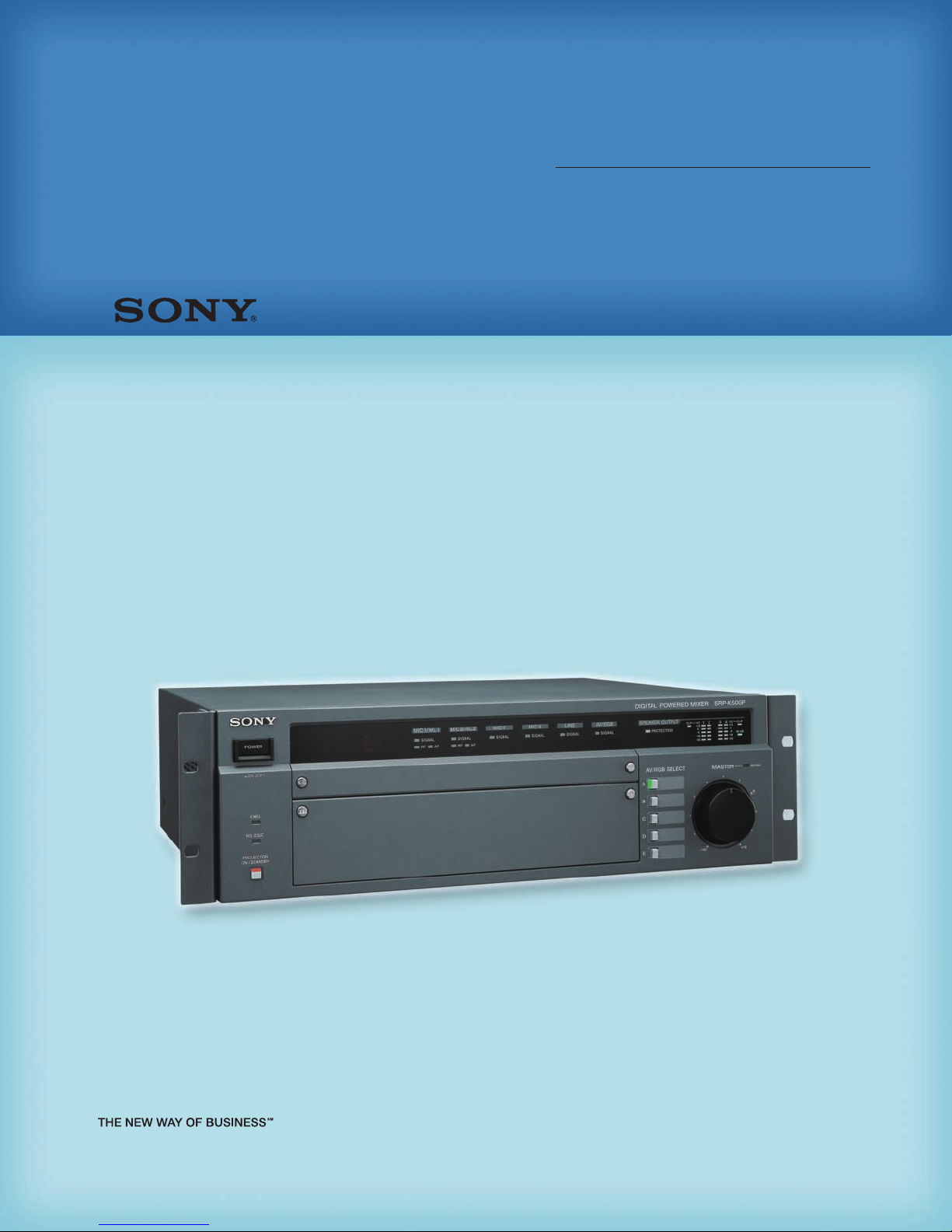
SRP-X500P
System Integration Guide

Table of Contents
1. Introduction ...................................................................................................... 3
2. Differences Between the SRP-X500P and SRP-X700P
2-1. Features.................................................................................................... 4
2-2. Comparison Chart..................................................................................... 5
3. Panel View
3-1. Front Panel ............................................................................................... 6
3-2. Rear Panel................................................................................................. 8
4. Setting up the SRP-X500P
4-1. SYSTEM TYPE........................................................................................... 10
What is a “SYSTEM TYPE”?
SYSTEM TYPE 1, 2 (for AV Presentation Rooms)
SYSTEM TYPE 4, 5 (for Conference Rooms
SYSTEM TYPE 3, 6, 7, 8, 9 (for Audio-Visual Rooms)
SYSTEM TYPE 0
Feedback Reducer
4-2.
........................................................................................ 12
5. Setting up the SRP-X500P Using Manager Software
5-1. Automatic Gain Control (AGC)................................................................. 14
5-2. Delay....................................................................................................... 15
5-3. Parallel Remote....................................................................................... 16
Connectable Devices to PARALLEL REMOTE Input Pins
MASTER Volume Muting
PROJECTOR POWER ON/STANDBY
Input Signal Selection for the AV/RGB INPUT Connector
MASTER Volume Control
Scene Recall
Remote Fader Level Control
5-4. Projector Control .................................................................................... 20
Outline
Setting Procedure
SECTION A: PROJECTOR PROTOCOL Select Switch Setting
SECTION B: Cable Connection
SECTION C: Input Video Signal Format and Projector Power Setting
SECTION D: Projector Control Using the Protocol Setting Function
............................................................................................ 19
.................................................................................................... 20
........................................................................ 10
........................................ 10
) ............................................... 11
.................................... 11
................................................................................... 13
............................ 16
.......................................................................... 16
............................................................ 17
......................... 18
.......................................................................... 18
.................................................................... 19
................................................................................... 20
....................... 21
................................................................. 21
....... 22
........ 22
6. Appendix
eedback
F
Automatic Gain Control (AGC)
Effect of Delay
Connecting High-impedance Speakers/Low-impedance Speakers
Programming a Learning-type Remote Commander
Block Diagram
ASCII - HEX Conversion Table
Connecting Status LEDs on the P
System Configuration
Specifications
Dimensions
2
................................................................................................. 25
.................................................................. 25
......................................................................................... 26
......................................................................................... 29
................................................................... 30
............................................................................. 31
.......................................................................................... 32
............................................................................................. 32
arallel Port
.......... 27
............................... 27
........................................... 30
1
Introduction
As a leading manufacturer in the A/V industry, Sony offers a wide range of
public address and sound reinforcement products utilizing sophisticated Sony
audio, wireless and interfacing technologies to provide a comprehensive business
and industrial product line.
In 2002, Sony introduced an innovative all-in-one system concept for multimedia
presentations, the SRP-X700P Digital Powered Mixer. Designed to function as
the central control hub for the integration of video, audio and PC media sources,
this mixer allows for rich content and multimedia presentation systems to be
easily configured, without integrating several separate A/V presentation devices.
Best suited for use with in mid- to large-scale conference rooms, seminar rooms,
and audio-visual rooms, the SPR-X700P is now widely accepted in many different
arenas including education, and the corporate and public sectors.
In 2005, expanding on this all-in-one concept, Sony introduced the SRP-X500P
This cost-effective mixer is an ideal choice in small to mid-scale presentation
systems that are typically used in conference rooms, corporate boardrooms,
classrooms, and houses of worship.
Soon after the launch of the SRP-X500P, however, system integrators and
installers were confronted with questions: What is the best choice for a specific
application – the SRP-X500P or the SRP-X700P? What are the differences
between these two mixers?
To help answer these questions, this guide provides the following useful
information:
• Using the maximum functionality and performance of the SRP-X500P
• Understanding the differences between the SRP-X500P and the SRP-X700P
• Establishing an effective system using the key features of the SRP-X500P
• Professional audio terminologies related to the SRP-X500P and SRP-X700P
We hope this guide serves as a valuable asset to your SRP Series system
ation activities.
integr
.
3
S
RP-X500P System Integration Guide
2
Differences Between
the SRP-X500P and SRP-X700P
2-1. Features
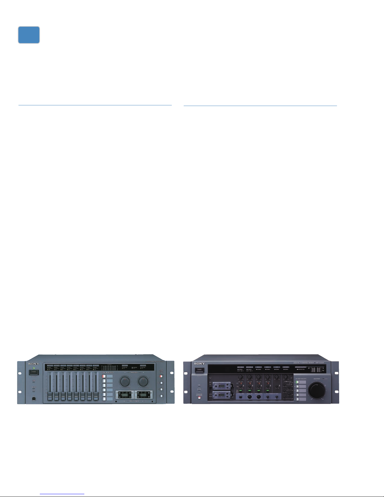
SRP-X700P
The SRP-X700P Digital Powered Mixer has been designed
for multimedia presentation systems that are required to
process material from a wide range of sources including
microphones, video, audio, DVD players, audio tape
recorders, and PCs. It incorporates the functionality of
seven major presentation devices – including a video/RGB
switcher, audio mixer, wireless tuner slots, sound processor,
and two-channel digital power amplifier – in a compact
3U-high chassis. Equipped with a comprehensive remote
control capability, and a variety of interfaces, the SRP-X700P
can easily be configured into a flexible system, and is an
ideal mid- to large-scale presentation system. The main
features of the SRP-X700P are as follows:
• Processes and mixes six microphone inputs (4 MIC,
2 MIC/LINE)
(Audio input CH1/CH2 is compatible with wired and
wireless microphones)
• Eight BUS outputs and two REC outputs to configure a
large system
• Built-in high-powered two-channel digital power
amplifier: 150 W + 150 W (8 Ω)
• Support for 5.1-channel surround audio input/output
• Comprehensive remote control of the SRP-X700P and
external peripherals such as a projector via a wide array
of interfaces (USB, RS-232C, Parallel, Control S)
Supplied SRP-X700P User Control P
•
easy system setup and operation from a PC
anel software for
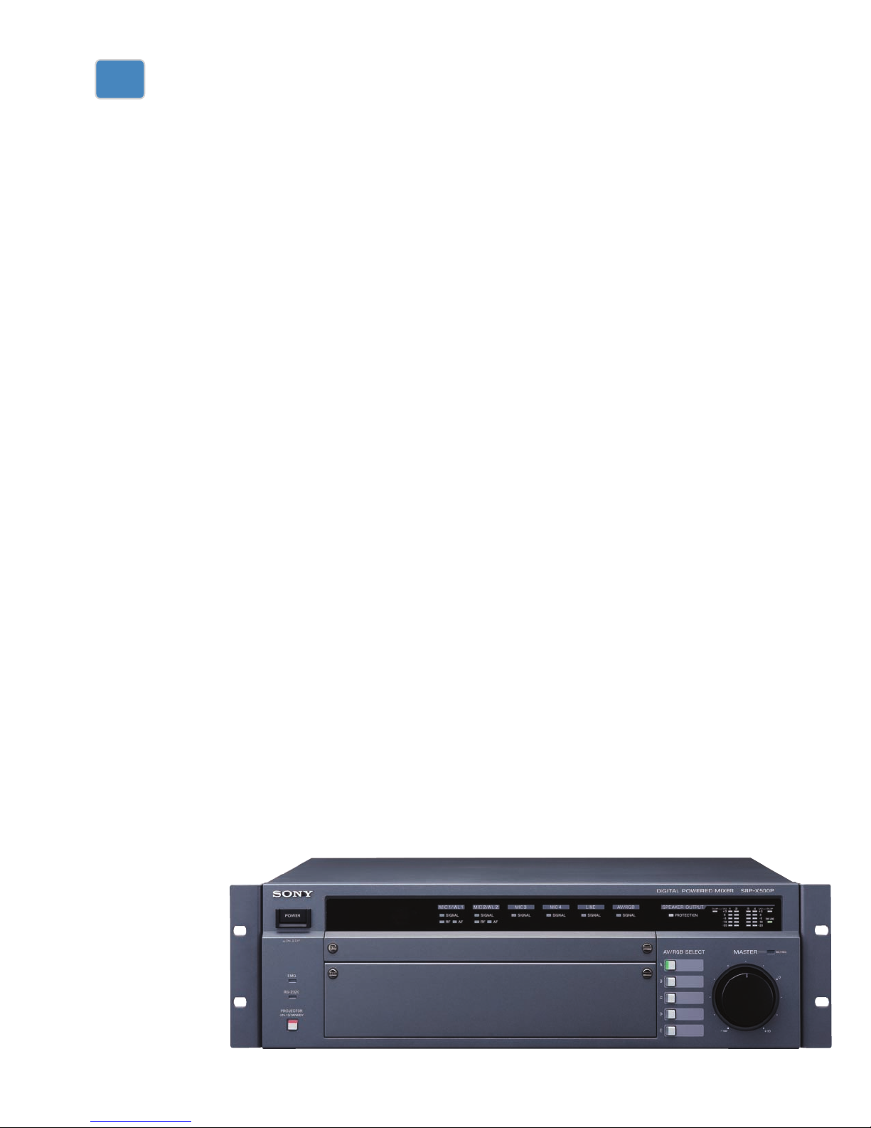
SRP-X500P
Inheriting rich features from the SRP-X700P, the SRP-X500P
provides a cost-effective solution and is ideal for use in
small to mid-scale presentation systems. For smooth
control over presentations, there is an easy-to-use frontpanel layout, providing instant-access controls. A built-in
four-channel power amplifier eliminates the need for
additional power amplifiers, enhancing the all-in-one
system concept.
The SRP-X500P offers nine system presets (factory default
system settings) in its memory, enabling quick setup of the
audio system by recalling the one best suited for each
venue. The main features of the SRP-X500P are as follows:
• Processes and mixes four microphone inputs
(Audio input CH1/CH2 is compatible with wired and
wireless microphones)
• Built-in four-channel digital power amplifier:
90 W + 90 W + 50 W + 50 W (8 Ω)
• Nine system presets stored in memory – allows simple
system configuration
• Easy-to-use front-panel layout with hardware switches
for projector controls and feedback reducer function
• Supplied front cover to prevent accidental operation
SRP-X700P (two optional tuner units installed)
4
SRP-X500P (two optional tuner units installed)

2 D
ifferences Between the SRP-X500P and SRP-X700P
2-2. Comparison Chart
SRP-X500P SRP-X700P
Power amplifier Low-impedance (8 Ω) 90 W x2 + 50 W x2 150 W x2
70V LINE 60 W, Mono 150 W, Mono
5
.1CH IN/OUT N/A Yes
VIDEO IN/OUT RGB IN/OUT 2 IN/1 OUT 3 IN/1 OUT
Component switching Yes Yes
S-VIDEO IN/OUT N/A 3 IN/1 OUT
VIDEO IN/OUT 3 IN/1 OUT 3 IN/1 OUT
A
UDIO IN MONO 4 6
TRIM (MONO)
STEREO 2 2
TRIM (STEREO) -30 dBu to 0 dBu -10 dBu to 0 dBu
AV SELECT 5 6
AUDIO OUT Master 4 8
REC OUT (L/R) N/A* Yes
GUI (setting software) Yes (RS-232C) Yes (USB)
Settings System preset Yes (selectable from front panel) N/A
Routing Yes Yes
Feedback reducer Yes Yes
Comp./Limiter Yes Yes
Parametric equalizer Yes (IN/OUT) Yes (IN/OUT)
Delay Yes Yes
Automatic mixer N/A Yes
Automatic Gain Control (AGC) Yes N/A
Projector control Yes Yes
PROJECTOR POWER ON/STANDBY switch Yes (front panel button) Yes (using SCENE RECALL)
IR remote control
V transport control No (use optional remote controller) Yes (4 Control S ports supplied)
A
External
SCENE RECALL Yes (via parallel port or RS-232C) Yes (via front panel switches, parallel port, and RS-232C)
* LINE OUTPUT CH-3/-4 is set to REC OUT in factory default settings
-60 dBu to -30 dBu -60 dBu to -45 dBu
Yes (optional) N/A
.
5
S
!• !¶ !§ !¢ !£ !™ !¡ !º
9
8
7654321
!∞
RP-X500P System Integration Guide
3
Panel View
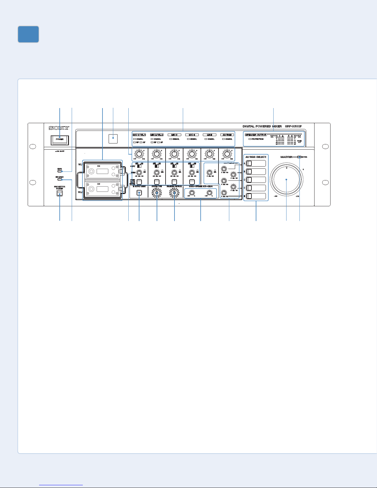
3-1. Front Panel
1 POWER switch
Turns the SRP-X500P on and off.
With the SRP-X500P Manager software,
you can link projector or display monitor
power on/standby control to that of the
SRP-X500P. For more details, refer to
the Projector Control section (5-4.).
2 EMG (emergency) indicator
Lights up red when an emergency
broadcast system connected to the
REMOTE PARALLEL connector cuts the
SPEAKER and LINE outputs.
3 Wireless microphone slots
(WL1/WL2)
Accommodates up to two WRU-806A/
806B (not supplied) or URX-X1 tuner
module (not supplied) included in the
UWP-X1/X2.
4 Remote emitter/sensor
oint an optional remote commander
P
towards the emitter/sensor
optional learning-type IR remote
controller, you can wirelessly control
frequently accessed SRP-X500P and
connected projector operations. For
. Using an
more details, refer to Programming a
Learning-type Remote Commander in
the appendix.
5 Input level controls
Rotate to adjust the input signal level:
MIC1/WL1: Adjusts the level of the
signal input from the MIC INPUT 1
connector or the tuner unit installed in
the WL1 slot.
MIC2/WL2: Adjusts the level of the
signal input from the MIC INPUT 2
connector or the tuner unit installed in
the WL2 slot.
MIC3: Adjusts the level of the signal
input from the MIC INPUT 3 connector.
MIC4: Adjusts the level of the signal
input from the MIC INPUT 4 connector.
LINE: Adjusts the level of the signals
input from the LINE IN connectors.
AV/RGB: Adjusts the level of the
signals input from the AV/RGB INPUT
audio connectors, as specified by the
AV/RGB SELECT buttons.
6 Input indicators
SIGNAL (signal level) indicators:
Lights up green when the signal is
0
input from each audio connector.
RF (radio frequency) indicators:
Lights up green when the level of the
RF signal input from each tuner unit is
satisfactory.
AF (audio frequency) indicators:
Light up yellow when the signal is input
from each tuner unit.
7 SPEAKER OUTPUT indicators
PROTECTION (protection circuit)
indicator:
protection circuit of the internal power
amplifier is activated.
CLIP (clip) indicators: Lights up red
when the output level of the internal
power amplifier is excessive and the
output signal is distorted.
70V LINE (high-impedance speaker
connection) indicator:
green when the SPEAKERS CH-3/4
terminals are set to connect highimpedance speakers (70V LINE).
VU (volume unit) meters: Uses fivesegment LEDs to indicate the signal
output level prior to adjustment by the
!™ SPEAKER OUT controls.
Lights up red when the
Lights up
6

3 P
anel View
8 MASTER MUTING indicator
Lights up red when signal output is
muted by a command from a device
connected to the REMOTE PARALLEL or
REMOTE RS-232C connector, or by
operation of an optional remote
commander.
9 MASTER control
Adjusts the output level of the assigned
channels. With the SRP-X500P
Manager software, you can specify
which output channels are controlled by
the MASTER control. In the factorypreset setting, the MASTER control is
assigned to control output from the
SPEAKERS CH-1 to 4 terminals and the
LINE OUTPUT 1/2 connectors. (Note
that the output from the LINE OUTPUT
3/4 terminals cannot be controlled.
However, by using SRP-X500P Manager
software, settings can be customized to
allow LINE OUTPUT 3/4 connectors to
be controlled by the MASTER control
and/or the REMOTE PARALLEL
connector.)
!º AV RGB SELECT buttons (A to E)
Press to select a device connected to the
AV/RGB INPUT audio/video connectors.
The pressed button lights up green.
!¡ LINE AV/RGB input adjustment
section
TRIM (input reference level
adjustment) controls:
Adjusts the
reference level for the audio signals
input from the LINE IN connectors and
the AV/RGB INPUT audio connectors.
The adjustable range is -30 dBu to
0 dBu.
REF. (reference level) indicators:
Lights up yellow when an audio signal
with a level in excess of the reference
level is input to the LINE IN connectors
and the AV/RGB INPUT audio connectors.
While the audio signal is input
, adjust the
TRIM controls so that the REF. indicators
light up yellow intermittently.
!™ SPEAKER OUT controls
Used to attenuate the output level of
the internal power amplifier. Before
adjusting the speaker output level, use
the TRIM controls to specify the
reference level for the audio input
signals, then use the MASTER control to
adjust the overall level. And then use
the SPEAKER OUT controls to adjust
output levels from the SPEAKERS
CH-1/2 terminals and CH-3/4 terminals.
!£ PROJECTOR PROTOCOL selector
Used to select the protocol
corresponding to the model of the
projector or display monitor connected
to the PROJECTOR CONTROL RS-232C
connector or the CONTROL S IN/OUT
connectors. For control of an LCD Data
Projector VPL-PX15, use the CONTROL S
connectors.
!¢ SYSTEM TYPE selector
Select 1 to 9 according to the speaker
configuration of the AV system being
used. The setting becomes effective
next time the power is turned on. For
more details, refer to the SYSTEM TYPE
section (4-1.).
!∞ IR OUTPUT MODE (remote
amming) button
progr
Used to program an SRP-X500P
command to an optional learning-type
or more details,
remote commander
. F
refer to Programming a Learning-type
Remote Commander in the appendix.
!§ Microphone input adjustment
section
+48V (48 V DC power supply)
ON/OFF switches:
Set to ON to supply
48 V DC power to condenser
microphones connected to the MIC
INPUT 1 to 4 connectors. Before
turning these switches, be sure to fully
turn down all input level controls and
the LINE AV/RGB controls, or turn off
the unit.
TRIM (microphone input reference
evel adjustment) controls:
l
et the
S
reference level for signals input from the
MIC INPUT 1 to 4 connectors. The
djustable range is -60 dBu to -30 dBu.
a
REF. (reference level) indicators:
Lights up yellow when an audio signal
with a level in excess of the reference
level is input to the MIC INPUT 1 to 4
connectors. While the audio signal is
input, adjust the TRIM controls so that
the REF. indicators light up yellow
intermittently.
FEEDBACK REDUCER (howling
suppressor) buttons:
Used to turn the
howling noise reducing function on or
off, and to make settings for this
function. The buttons light up green
when the function is turned on. For
more details, refer to the Feedback
Reducer section (4-2.).
!¶ RS-232C indicator
Lights up green when the SRP-X500P
and a PC or external controller are
communicating via the REMOTE
RS-232C connector.
!• PROJECTOR ON/STANDBY
POWER switch
Turns on the projector or display
monitor connected to the SRP-X500P, or
sets the projector to standby status.
Press the switch while it is lit up red
(i.e., the projector is in standby) to turn
on the projector. The switch lights up
green when the projector is turned on.
To turn off the projector, hold down the
switch for more than two seconds. The
switch flashes green while the projector
cools off, and then lights up red when
the projector enters standby.
7
S
!¢ !£ !™ !¡ !º 9 8
71 654321
RP-X500P System Integration Guide
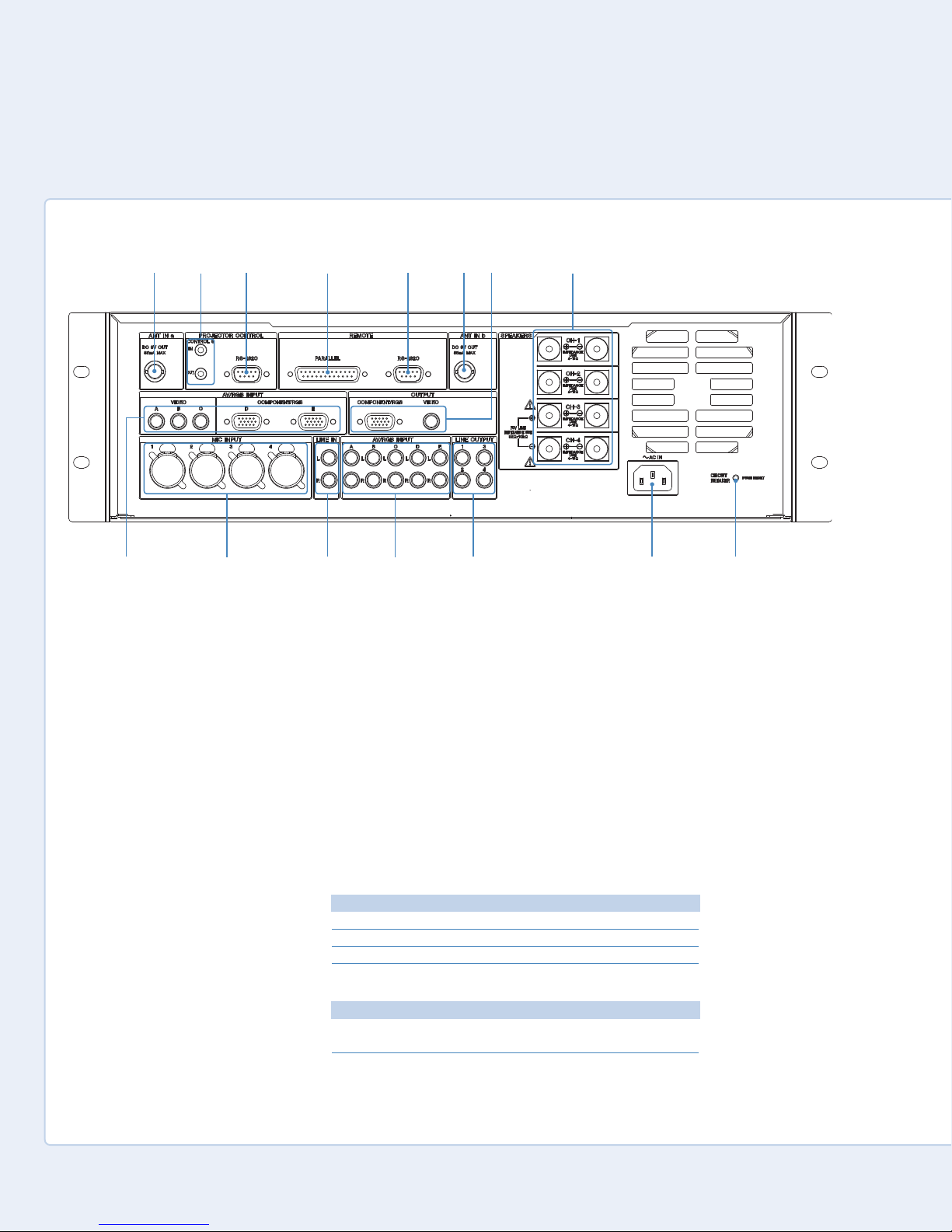
3-2. Rear Panel
1 ANT IN a/b connectors
(BNC-type)
Connect antennas for the tuner unit
installed in the SRPX-500P. Only the
supplied antennas or the optional UHF
Antenna AN-820A can be used.
2 PROJECTOR CONTROL
CONTROL S IN/OUT connectors
(stereo mini jack)
Used to control the L
CD Data Projector
VPL-PX15 exclusively.
3 PROJECTOR CONTROL RS-232C
connector (D-sub, 9-pin, male)
Used to control a projector or display
monitor with an RS-232C connector
that is connected to the
6 OUTPUT
COMPONENT/RGB or OUTPUT VIDEO
connector of the SRP-X500P.
4 REMOTE PARALLEL connector
(D-sub, 25-pin, female)
This connector consists of 10 input pins
and 10 output pins. The SRP-X500P can
be controlled by a switch or volume
controller connected to the input pins.
Connecting these pins to an emergency
broadcast system allows the audio
output of the SRP-X500P to be cut off
during an emergency broadcast.
The following devices can be
connected to this connector:
Input pins
Connectable device
Switch Volume With 10 kΩ, B-curve
Emergency broadcast system Connected via relay
Output pins
Connectable device
LED 24 V DC or less, 40 mA or less
Relay 24 V DC or less, 40 mA or less
8

3 P
anel View
5 REMOTE RS-232C connector
(D-sub, 9-pin, male)
his is an RS-232C serial connector for
T
remote control. When a PC is
connected, parameters can be set using
the SRP-X500P Manager software. The
SRP-X500P can be controlled from the
external controller connected to the
REMOTE RS-232C connector.
6 OUTPUT connector section
These connectors output the video
signal input from the AV/RGB INPUT
video connectors. Signal format
conversion is not carried out.
COMPONENT/RGB connector
(HD D-sub, 15-pin, female):
Outputs
component or RGB signals.
VIDEO connector (phono jack):
Outputs composite signals.
7 SPEAKERS CH terminals (1 to 4)
(screw terminal)
These are the output terminals of the
internal power amplifiers. For more
details, refer to Connecting Highimpedance Speakers/Low-impedance
Speakers in the appendix.
8 CIRCUIT BREAKER button
The circuit breaker cuts off the main
ower when excessive current flows
p
through the AC IN connector. If the
circuit breaker trips, press the CIRCUIT
BREAKER button to reset the breaker,
but do not use the SRP-X500P. Instead,
turn it off and contact the Sony dealer
from whom you purchased the unit.
9 AC IN connector
Connects the supplied AC power cord.
!º LINE OUTPUT connectors (1 to 4)
(phono jack)
Connect to the line input connectors of
a power amplifier, CD/MD recorder, etc.
The LINE OUTPUT 3/4 is set to REC OUT
in factory default settings. SRP-X500P
Manager software settings can be
changed in order to use LINE OUTPUT
3/4 connectors for other purposes.
!¡ AV/RGB INPUT audio connectors
(A to E) (phono jack)
Connect to the audio output connectors
of devices with video output connection
to SRP-X500P
!¢ AV/RGB INPUT video
connectors. When connecting a device,
e that each output connector on
be sur
the device is connected to the A
V/RGB
INPUT video and audio connector on
the SRP-X500P with the corr
esponding
letter (A to E).
!™ LINE IN connectors (phono jack)
Connect to the line output connectors
f a CD player, MD recorder, etc.
o
!£ MIC INPUT connectors (1 to 4)
(XLR-3-31-type)
Connect wired microphones. When
wired microphones are connected to
the MIC INPUT 1/2 connectors, input
signals from the wireless microphones
take priority from the moment the
tuner units begin receiving the signal.
!¢ AV/RGB INPUT video connectors
(A to C: phono jack; D and E:
HD D-sub, 15-pin, female)
Connect to the video output connectors
of devices with audio output connection
to SRP-X500P
!¡ AV/RGB INPUT audio
connectors. When connecting a device,
be sure that each output connector on
the device is connected to the AV/RGB
INPUT video and audio connector on
the SRP-X500P with the corresponding
letter (A to E).
9

S
SP 2
70V LINE
(SP 3-4)
SP 1
SP 2
SP 3 SP 4
SP 1
SP 2
SP 1
SP 2
SP 1
SP 3
SP 4
A
70V LINE
(SP 3-4)
SP 1 SP 2 SP 3 SP 4
AV Presentaion Room
SYSTEM TYPE 1 (70V LINE)
SYSTEM TYPE 4 (70V LINE)
SYSTEM TYPE 2 (Lo-imp)
SYSTEM TYPE 5 (Lo-imp)
SYSTEM TYPE 3 SYSTEM TYPE 6 to 9
Conference Room
Audio-Visual Room
SP 2
70V LINE
(SP 3-4)
SP 1
SP 2
SP 3 SP 4
SP 1
SYSTEM TYPE 1 (70V LINE)
SYSTEM TYPE 2 (Lo-imp)
LINE,
AV/RGB R
LINE,
AV/RGB L
LINE,
AV/RGB R
LINE,
AV/RGB L
MIC
MIC
MIC
LINE
AV/RGB
MIC
LINE
AV/RGB
SRP-X500P SRP-X500P
SP 1
SP 2
SP 1
SP 2
SP 3-4
(70V LINE)
IN
OUT
IN
OUT
When using high-impedance ceiling speakers
SP 3
(Lo-imp)
SP 4
(Lo-imp)
When using low-impedance ceiling speakers
{
{
RP-X500P System Integration Guide
4
Setting up the SRP-X500P
4-1. SYSTEM TYPE
What is a “SYSTEM TYPE”?
The SRP-X500P offers nine factory default system settings
called “SYSTEM TYPE” in its memory, enabling efficient
audio adjustment. Depending on the type of room,
speaker locations, and speaker system configurations, you
can quickly configure an audio system by recalling the bestsuited preset for each venue. If your requirements cannot
be managed by one of the nine system presets provided,
you can easily customize all system settings using the
supplied SRP-X500P Manager software.
SYSTEM TYPE 1, 2 (for AV Presentation Rooms)
SYSTEM TYPE 1 and 2 are suitable for AV presentation
rooms. This type of room needs clear voice reproduction
from microphones, and vivid sound from AV equipment
such as DVD and CD players. Satisfying both requirements,
the following may be the best speaker configuration:
• Output microphone audio from ceiling speakers to
enhance clarity
• Output AV equipment audio from the front speakers in
stereo
For ceiling speakers, both multi-connected high-impedance
speakers and high-quality low-impedance speakers can be
used.
The SRP-X500P is equipped with a four-channel digital
power amplifier (SP1 to SP4). Low-impedance speakers can
be connected to SP1 and SP2, while SP3 and SP4 can be
switched between high- and low-impedance modes. This
means you can configure systems as follows:
• SYSTEM TYPE 1: a pair of front speakers and
high-impedance ceiling speakers (70V Line)
• SYSTEM TYPE 2: a pair of front speakers and
low-impedance ceiling speakers (Lo-imp)
10
 Loading...