

SONY SRW-1, SRPC-1 User Manual

HD PORTABLE DIGITAL RECORDER
SRW-1
HD VIDEO PROCESSOR
SRPC-1
OPTICAL INTERFACE UNIT
HKSR-101
OPERATION MANUAL [English]
1st Edition (Revised 2)
WARNING
To prevent fire or shock hazard, do not
expose the unit to rain or moisture.
To avoid electrical shock, do not open the
cabinet. Refer servicing to qualified
personnel only.
For the customers in the USA
This equipment has been tested and found to comply with the
limits for a Class A digital device, pursuant to Part 15 of the
FCC Rules. These limits are designed to provide reasonable
protection against harmful interference when the equipment is
operated in a commercial environment. This equipment
generates, uses, and can radiate radio frequency energy and,
if not installed and used in accordance with the instruction
manual, may cause harmful interference to radio
communications. Operation of this equipment in a residential
area is likely to cause harmful interference in which case the
user will be required to correct the interference at his own
expense.
You are cautioned that any changes or modifications not
expressly approved in this manual could void your authority to
operate this equipment.
The shielded interface cable recommended in this manual
must be used with this equipment in order to comply with the
limits for a digital device pursuant to Subpart B of Part 15 of
FCC Rules.
For the customers in the USA and Canada
RECYCLING LITHIUM-ION BATTERIES
Lithium-Ion batteries are recyclable.
You can help preserve our environment
by returning your used rechargeable
batteries to the collection and recycling
location nearest you.
For more information regarding recycling of rechargeable
batteries, call toll free 1-800-822-8837, or visit
http://www.rbrc.org/
Caution: Do not handle damaged or leaking lithium-ion
batteries.
For the customers in Europe
This product with the CE marking complies with the EMC
Directive (89/336/EEC) issued by the Commission of the
European Community.
Compliance with these directives implies conformity to the
following European standards:
• EN55103-1: Electromagnetic Interference (Emission)
• EN55103-2: Electromagnetic Susceptibility (Immunity)
This product is intended for use in the following
Electromagnetic Environment(s):
E1 (residential), E2 (commercial and light industrial), E3
(urban outdoors) and E4 (controlled EMC environment, ex. TV
studio).
For HKSR-101 only
This Optical Interface Unit is classified as a CLASS 1
LASER PRODUCT.
Laser diode properties
Wave length: 1310±20 nm
Emission duration: Continuous
Laser output power: 10 mW (max.)
Daten der Laserdiode
Wellenlänge: 1310±20 nm
Emissionsdauer: Kontinuierlich
Laser-Ausgangsleistung: 10 mW (max.)
Laserdiode data
Bølgelængde: 1310±20 nm
Strålingsvarighed: Kontinuerlig
Lasereffekt: 10 mW (max.)
Laserdiodens egenskaper
Våglängd: 1310±20 nm
Strålningstid: utan avbrott
Laseruteffekt: 10 mW (max.)
Laserdiodens egenskaper
Bølgelengde: 1310±20 nm
Emisjonslengde: Kontinuerlig
Laser utgangseffekt: 10 mW (max.)
CAUTION
The use of optical instruments with this product will
increase eye hazard.
CAUTION
Use of controls or adjustments or performance of
procedures other than those specified herein may result in
hazardous radiation exposure.
This device complies with part 15 of the FCC Rules.
Operation is subject to the following two conditions: (1) this
device may not cause harmful interference, and (2) this
device must accept any interference received, including
interference that may cause undesired operation.
For customers in Canada
This Class A digital apparatus complies with Canadian
ICES-003.
Voor de Klanten in Nederland
Gooi de batterij niet weg maar lever deze in als klein chemisch
afval (KCA).
2

VORSICHT
Um Feuergefahr und die Gefahr eines
elektrischen Schlages zu vermeiden, darf
das Gerät weder Regen noch Feuchtigkeit
ausgesetzt werden.
Pour plus d’informations sur le recyclage des accumulateurs,
téléphonez au numéro gratuit
1-800-822-8837 (Etats-Unis et Canada uniquement), ou
visitez http://www.rbrc.org/
Avertissment: Ne pas utiliser des accumulateurs aux ions de
lithium qui sont endommagés ou qui fuient.
Um einen elektrishen Schlag zu vermeiden,
darf das Gehäuse nicht geöffnet werden.
Überlassen Sie Wartungsarbeiten stets nur
qualifiziertem Fachpersonal.
Für Kunden in Europa
Dieses Produkt besitzt die CE-Kennzeichnung und erfüllt die
EMV-Richtlinie (89/336/EWG) der EG-Kommission.
Angewandte Normen:
• EN55103-1: Elektromagnetische Verträglichkeit
(Störaussendung)
• EN55103-2: Elektromagnetische Verträglichkeit
(Störfestigkeit),
für die folgenden elektromagnetischen Umgebungen:
E1 (Wohnbereich), E2 (kommerzieller und in beschränktem
Maße industrieller Bereich), E3 (Stadtbereich im Freien) und
E4 (kontrollierter EMV-Bereich, z.B. Fernsehstudio).
Für Kunden in Deutshland
Entsorgungshinweis: Bitte werfen Sie nur entladene Batterien
in die Sammelboxen beim Handel oder den Kommunen.
Entladen sind Batterien in der Regel dann, wenn das Gerät
abschaltet und signalisiert “Batterie leer” oder nach längerer
Gebrauchsdauer der Batterien “nicht mehr einwandfrei
funktioniert”. Um sicherzugehen, kleben Sie die Batteriepole
z.B. mit einem Klebestreifen ab oder geben Sie die Batterien
einzeln in einen Plastikbeutel.
Pour les utilisateurs au Canada (HKSR-101 seulement)
Cet appareil numérique de la classe A est comforme à la
norme NMB-003 du Canada.
Pour les clients européens
Ce produit portant la marque CE est conforme à la Directive
sur la compatibilité électromagnétique (EMC) (89/336/CEE)
émise par la Commission de la Communauté européenne.
La conformité à cette directive implique la conformité aux
normes européennes suivantes:
• EN55103-1: Interférences électromagnétiques (émission)
• EN55103-2: Sensibilité électromagnétique (immunité)
Ce produit est prévu pour être utilisé dans les environnements
électromagnétiques suivants:
E1 (résidentiel), E2 (commercial et industrie légère), E3
(urbain extérieur) et E4 (environnement EMC contrôlé, ex.
studio de télévision).
For the customers in Taiwan only
AVERTISSEMENT
Afin d’éviter tout risque d’incendie ou
d’électrocution, ne pas exposer cet
appareil à la pluie ou à l’humidité.
Afin d’écarter tout risque d’électrocution,
garder le coffret fermé. Ne confier
l’entretien de l’appareil qu’à un personnel
qualifié.
Pour les utilisateurs aux Etats-Unis et au Canada.
RECYCLAGE DES ACCUMULATEURS AUX IONS DE
LITHIUM
Les accumulateurs aux ions de lithium sont
recyclables.
Vous pouvez contribuer à préserver
l’environnement en rapportant les piles
usées dans un point de collection et
recyclage le plus proche.
3

Table of Contents
Chapter 1 Overview
1-1 Features.................................................7
1-1-1 Principal Features ................................ 7
1-1-2 HDCAM-SR Format............................8
1-2 System Configuration.........................10
Chapter 2 Names and Functions of
Parts
2-1 SRW-1 ..................................................11
2-1-1 Principal Sections .............................. 11
2-1-2 Control Panel .....................................12
2-1-3 Display...............................................14
2-1-4 Connector Panel................................. 16
2-2 SRPC-1.................................................18
Chapter 3 Preparations
3-1 Assembly.............................................21
3-1-1 Joining the SRW-1 and SRPC-1........ 21
3-1-2 Using the Control Panel Extension
Cable ..................................................23
3-2 Connections ........................................25
3-2-1 Connections for Recording ................25
3-2-2 Connections for Playback ..................27
3-3 About Reference Sync Signals.......... 28
3-3-1 Reference Signals for Video Output
Signals................................................ 28
3-3-2 Connecting Reference Signals
(Examples for When External Sync Is
Required) ...........................................29
3-4 Power Supply Preparations ...............32
3-4-1 Using a Battery Pack .........................32
3-4-2 Using AC Power................................ 32
3-4-3 Powering On and Off.........................33
3-4-4 Checking the Power and Voltage ......33
3-5 Display Settings..................................34
3-6 Superimposed Text Information........ 34
3-7 Handling Cassettes.............................36
3-7-1 Usable Cassettes ................................ 36
3-7-2 Inserting and Ejecting Cassettes ........36
3-7-3 Preventing Accidental Erasure ..........37
Chapter 4 Menu Settings
4-1 Basic Menu Operations......................39
4-1-1 Displaying Menus..............................39
4-1-2 Changing Menu Settings....................39
4-2 TC Setup Menu....................................41
4-3 VIDEO Setup Menu .............................45
4-4 AUDIO Setup Menu.............................46
4-5 SYSTEM Setup Menu..........................48
Chapter 5 Recording and Playback
5-1 Signal Format Settings.......................51
5-1-1 Selecting the System Signal Format ..51
5-1-2 TeleFile Recording ............................52
5-2 Recording Preparations and
Operations ..........................................53
5-2-1 Selecting the Recording Source (When
Optional HKSR-101 Is Installed).......53
5-2-2 Selecting Signals to Output to the HD
Monitor ..............................................53
5-2-3 Making Audio Signal Settings...........54
5-2-4 Setting Recording Audio Levels........55
5-2-5 Making Timecode and User Bits
Settings...............................................55
5-2-6 Recording Operations ........................57
5-3 Playback Preparations and
Operations ..........................................59
5-3-1 Selecting the Conversion Mode of the
Downconverter...................................59
5-3-2 Making Audio Monitor Signal
Settings...............................................59
5-3-3 Adjusting Playback Audio Levels .....59
5-3-4 Selecting Time Data to Display During
Playback.............................................59
5-3-5 Playback Operations ..........................60
Appendixes
Maintenance and Inspections.................. 61
Head Cleaning .............................................61
Handling the Optical-Fiber Connector (When
Optional HKSR-101 Is Installed).......61
Condensation ...............................................61
Specifications............................................62
General ........................................................62
4
Table of Contents

Digital Video System ..................................62
Digital Audio System ..................................62
Input Connectors .........................................62
Output Connectors.......................................63
Other Connectors.........................................63
Supplied Accessories...................................63
Optional Accessories...................................63
Recommended Accessories......................... 64
Error Messages and Warning
Messages...................................................64
About Error Messages .................................64
About Warning Messages ...........................67
Warning System........................................70
Index...........................................................73
Table of Contents
5

6
Table of Contents

Overview
1-1 Features
The SRW-1 is an HDCAM-SR
portable digital recorder. It is used together with the
SRPC-1 high-definition video processor.
1) HDCAM-SR is a trademark of Sony Corporation.
1-1-1 Principal Features
The SRW-1 and SRPC-1 have the following features.
1)
format high-definition
Chapter
Input interface
The input interface is based on the HD SDI (HD Serial
Digital Interface) format compliant to BTA S-004B/005B/
006B (SMPTE 291M/292M/299M) and ARIB STD B-4.
One component video signal, 12 channels of digital audio
signals, and a timecode signal are time-division
multiplexed and carried along a single (or a couple of)
coaxial cable(s) with BNC-type connectors. These signals
are separated and converted to parallel data.
Audio signals to record can be switched among the
following three: signals multiplexed into the HD SDI
signals described above, audio signals from the AES/EBU
digital interface, and analog audio signals from
microphones or other analog audio devices.
1
High-quality digital recording
The SRW-1 uses a Y/Pb/Pr component system and an
RGB component system to record video signals. An AES/
EBU format with a wide dynamic range is used for 12channel audio recording. Powerful error correction and
error concealment circuits unique to HDCAM-SR are used
in digital signal processing. Accurate and stable video
signal output can be obtained by adjusting the internal
video signal processor.
Recording and playback modes
You can select from the following recording and playback
modes.
1080 × 1920 (progressive): 23.98PsF, 24PsF, 25PsF,
29.97PsF
1080 × 1920 (interlaced): 59.94i / 50i
Double-speed recording
Drum rotation and tape transport can be increased to
double speed for high-speed data transfers, allowing twice
as much data to be recorded in the same time. 4:4:4 RGB
video can be recorded for even higher quality.
The output of two camera systems can be recorded
simultaneously on a single tape as 4:2:2 DUAL STREAM.
Output interface
Component video signals are converted into serial data,
multiplexed with audio signals and timecode, and output in
the HD SDI format. SD SDI output can also be obtained by
using the internal HD/SD converter board.
In addition to digital audio signals multiplexed into the HD
SDI signals described above, audio is output from the
AES/EBU digital interface, and analog audio is output
after D/A conversion.
Transmission over optical-fiber cable (with
optional HKSR-101 installed)
When the optional HKSR-101 Optical Interface Unit is
installed, this unit can be connected to an HDC-F950 HD
Color Video Camera by optical-fiber cable.
A single optical-fiber cable can receive HD 4:2:2
component video signals or HD 4:4:4 RGB video signals,
while simultaneously transmitting HD 4:2:2 component
video return signals to the camera. Audio signals and
control signals are multiplexed into video signals
transmitted over optical-fiber cable.
1-1 Features
7

Note
Power cannot be supplied to a camera from this unit by
Chapter 1 Overview
optical-fiber cable.
• Highly reliable narrow track recoding and playback
through high-performance, high-accuracy, drummounted heads.
These technologies allow extended high-definition
recording times on HDCAM-SR cassettes of the same size
Format conversion
This unit supports the following format conversions.
• Pulldown (23.98PsF
• 4:4:4 RGB
t 4:2:2 YPbPr
t 59.94i)
as the HDCAM cassette: 40 minutes or more on S-size
HDCAM-SR cassettes.
Digital signal processing
4:2:2 component video signals or 4:4:4 RGB signals
Removable control panel
The control panel is independent of the SRW-1 (VTR main
unit), allowing it to be installed in the most convenient
location in your operating environment. It can be held in
the hand and operated like a remote controller.
obtained by quantization according to ITU-R709, SMPTE
274M, and BTA S-002B (SMPTE 260M) are compressed
according to the MPEG-4 Studio Profile. Audio signals are
processed uncompressed, according to the AES/EBU
format.
Internal timecode generator and reader
The internal timecode generator allows you to record
timecode (LTC
1)
and user bit data
and audio signals. The internal timecode reader reads the
recorded timecode (LTC and user bit data) during
playback.
1) LTC (Longitudinal Time Code):
Timecode recorded on longitudinal tracks of the tape. It may not be read
correctly when the tape speed is very slow or when the tape speed changes
suddenly.
2) User bit data:
Eight-digit hexadecimal numbers which can be recorded as auxiliary
information during recording of timecode.
2)
) along with the video
Computer servo system
Computer-controlled servo motors provide direct drive for
the drum, capstan, and S-side reel, enabling quick and
accurate tape access.
Independent audio level adjustment
You can adjust audio levels independently while checking
peaks on all 12 audio channels.
Self diagnostics
When an error occurs, the system performs self diagnostics
and displays the cause.
1-1-2 HDCAM-SR Format
The HDCAM-SR format exploits advances in signal
processing and magnetic recording technology to enable
HD digital recording and playback with high image and
sound quality, with functionality comparable to that of the
HDCAM format.
• Highly efficient mild data compression based on the new
MPEG-4 Studio Profile
• Powerful error correction system
Bit rate reduction encoder
Component video signal data is compressed to specified
data rates by a process in which it is subjected to frame
shuffling, DCT (discrete cosine transform) or DPCM
(differential pulse code modulation), quantizing
adjustment, and variable length word encoding. This
process forms the core of the new MPEG-4 Studio Profile
compression strategy. The process uses intra-frame
compression for progressive image capture and intra-field
compression for interlaced images.
ECC encoder
An outer ECC (error correction code) is interleaved with
the compressed data, followed by inner ECC, ID data, and
sync data. The error correction system uses standard ReedSolomon codes.
Channel coding
Video and audio with the addition of ECC data are
recorded in the form of serial data. The HDCAM-SR
format uses a scrambled NRZI (Non-Return-to-Zero
Inverted) channel coding system to ensure superior offtrack and noise tolerance characteristics.
Playback signal processing
Digital playback signals are equalized by equalizer circuits
and error corrected by powerful inner and outer ECC. This
process corrects most noise and dropout problems in the
reproduced signal. Data that cannot be completely
corrected in this way is corrected by error concealment
circuits.
Tele-File
The SRW-1 supports the Tele-File memory label system.
1) Tele-File:
A system in which non-contact memory ICs on the spines of cassettes
1)
memory label system
8
1-1 Features

allow you to record and read data about the material on the cassettes. TeleFile is a trademark of Sony Corporation.
Chapter 1 Overview
1-1 Features
9

1-2 System Configuration
Chapter 1 Overview
The following figure shows a system configured around
the SRW-1 and SRPC-1.
HD color video camera
BP-GL95/IL75
Switching
BATTERY/
DC IN
Microphone
HD VTR etc.
HD SDI video/
audio input
HD SDI video/
audio output
SRW-5000
HD DIGITAL VIDEO CASSETTE RECORDER
SRW-5000/5500
HD color video camera
(HDC-F950)
AC-DN10/DN2B
AC-550
FC2-PD50/PD250
Optical-Fiber Cable
HKSR-101 Optical Interface Unit
SRW-1 + SRPC-1
Earphones
Headphones
HD video output (HD SDI)
SD video output (SDI)
SD video monitor
Audio input
Analog: 4 channels
AES/EBU: 4 channels
HD video monitor
VTR etc.
VTR,
FPU etc.
10
1-2 System Configuration
Audio output
Analog: 2 channels
AES/EBU: 12 channels
Stereo amplifier
Speakers
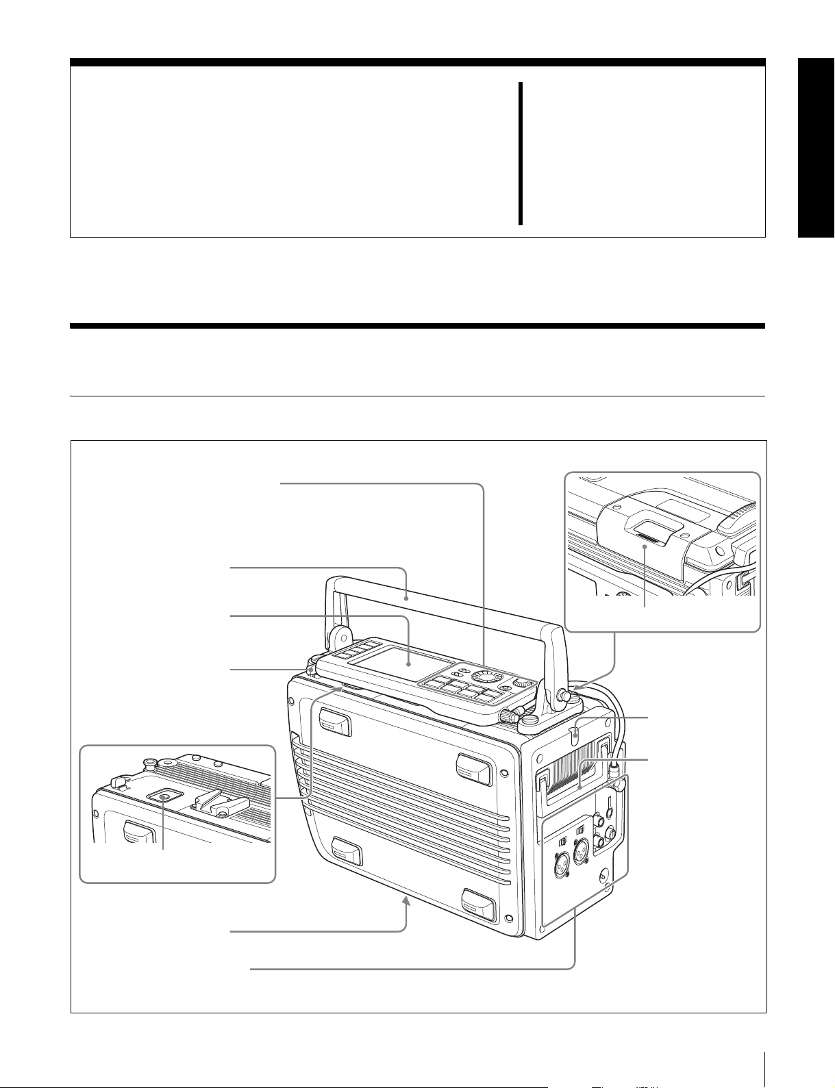
Names and Functions of
2-1 SRW-1
2-1-1 Principal Sections
Control panel (see page 12)
See 3-1-2 “Using the Control Panel
Extension Cable” (page 23) for more
information about using the control
panel apart from the recorder.
6 Top handle
Parts
Chapter
2
Display (see page 14)
5 Lock release button
(for control panel)
7 EJECT button
4 Processor connector
Connector panel (see page 16)
1 Cassette insertion slot
2 Tally indicator
3 Side handle
2-1 SRW-1
11

a Cassette insertion slot
Insert cassettes.
d Processor connector
Connect the SRPC-1 HD video processor.
For details, see 3-7-2 “Inserting and Ejecting Cassettes”
(page 36).
b Tally indicator
Chapter 2 Names and Functions of Parts
Lights during recording.
Flashes when errors have occurred (see “About Error
Messages” (page 64)) or when warnings have occurred
(see “About Warning Messages” (page 67)).
e Lock release button (for control panel)
When removing the control panel, use this button.
For more information about using this button, see 3-1-2
“Using the Control Panel Extension Cable” (page 23).
f Top handle
Use to carry the SRW-1 or joined SRW-1/SRPC-1.
If you need to remove the top handle from the SRW-1
For more information about the tally indicator operation,
body, use a coin driver, etc. to loosen the four screws.
see “Warning System” (page 70).
g EJECT button
c Side handle
When the top handle is removed, use this handle to join
Pressing this button opens the lid of the cassette insertion
slot, allowing you to take out the inserted cassette.
and separate the SRW-1 and SRPC-1.
2-1-2 Control Panel
1 Menu selection buttons
2 Display
3 KEY INHI switch
4 LIGHT switch
5 ADJUST knob
6 SELECT/ENTER dial
7 BACK button
8 Control panel
connection cable
ANLG
ANLG
SDI
SDI
SDI
SDI
SDI
SDI
SDI
SDI
A/E
4:2:2
A/E
EMP
EMP
EMP
EMP
L R
L R
L R
L R
9
10
11
12
SRW-1
INHI
RECINHI
F
1080
LOCAL
- - -
21:46
HOME
TC
VIDEO
AUDIO
SYSTEM
dB
0
-10
-20
-30
-60
EMP
EMP
EMP
EMP
EMP
EMP
EMP
L R
L R
L R
1
2
3
PLAY LOCK
OOOO
TCR
LTC
INTRPDFEXT-LK KEY
L R
4
EMP
L R
L R
L R
L R
5
6
7
8
00H00M00S00
12.2V REMAIN CH.COND
46min
23.98PsF
qa EJECT button
a Menu selection buttons
Select the menu shown on the display.
HOME button: Displays the HOME screen. The HOME
screen displays audio levels, operating status,
warnings, time data, and other information.
TC button: Displays the TC (timecode) Setup menu (see
pages 41 to 44). This menu allows you to switch
KEY INHI
OFF ON
LIGHT
OFF ON
EJECT STOP PLAY
xZzB
REW F FWD PAUSE
FUNC
mXM
ADJUST
SELECT/ENTER
BACK
REC
9 Tape transport control buttons
0 FUNC button
between LTC and VITC, to switch between DF and
NDF, and to display timecode on an external monitor.
VIDEO button: Displays the VIDEO Setup menu (see
page 45). This menu allows you to make settings
related to video.
AUDIO button: Displays the AUDIO Setup menu (see
page 46). This menu allows you to make settings
related to audio.
12
2-1 SRW-1

SYSTEM button: Displays the SYSTEM Setup menu
(see pages 48 to 50). This menu allows you to make
settings related to the entire systems, such as recording
format, power, and test signal output.
See Chapter 4 “Menu Settings” (page 39) for more
information about menus.
b Display
Displays menus, audio levels, warning, operating status,
time data, remaining tape time, and remaining battery
power.
For details, see 2-1-3 “Display” (page 14).
c KEY INHI (inhibit) switch
When the KEY INHI item (see page 49) in the SYSTEM
Setup menu is set to ALL, setting this switch to ON
disables operation buttons, to prevent misoperations due to
accidental button operations.
ON: All operation buttons are disabled.
OFF: During recording, only the STOP button and
PAUSE button are enabled. All buttons are enabled
when the system is not recording.
When the KEY INHI item in the SYSTEM Setup menu is
set to MAP, the operation buttons follow the settings of the
LOCAL KEYMAP item.
d LIGHT switch
The backlight comes on when this is set to ON.
e ADJUST knob
Use to adjust audio levels, etc.
f SELECT/ENTER dial
When a menu is displayed, you can rotate this dial to move
the cursor, and press it to change and confirm settings.
g BACK button
When a menu is displayed, you can press this button to
back up one level in the menu structure.
To start recording, press the button together with the
REC button.
REC button and indicator: Pressing the button together
with the PLAY button starts recording. The indicator
lights during recording.
If you press this button during stop, fast forward, or
rewind or when no cassette is inserted, the SRW-1
enters E-E mode
2)
signals
output from the HD SDI OUT A/B
1)
. In this mode you can monitor E-E
connectors or the MONITOR OUT HD SDI/SD SDI
connectors of the SRPC-1.
1) E-E mode:
A state in which E-E signals can be monitored. Commonly used to monitor
input signals before they are recorded.
2) E-E (electric to electric) signal:
A signal which passes solely through internal circuitry, and not through
pathways in which magnetic conversion takes place, such as magnetic
heads and tapes.
REW (rewind) button and indicator: Pressing the button
rewinds the tape. The indicator lights during
rewinding, and goes out when rewinding completes.
F FWD (fast forward) button and indicator: Pressing
the button fast forwards the tape. The indicator lights
during fast forwarding, and goes out when fast
forwarding completes.
PAUSE button and indicator: Pressing the button pauses
tape transport. The indicator flashes during pause.
To resume tape transport, press the button again.
j FUNC (function) button
Pressing this button together with another button selects
one of the following operations.
STOP button: Puts the SRW-1 into standby off mode.
HOME button: Switches the display at the bottom of the
HOME screen.
k EJECT button and indicator
Pressing the button opens the cover of the cassette
insertion slot so that you can remove a cassette. The
indicator lights during removal.
Chapter 2 Names and Functions of Parts
h Control panel connection cable
Connect to the SRW-1 CTRL PANEL connector.
i Tape transport control buttons
Use these buttons for tape transport operations.
STOP button: Stops tape transport.
Pressing this button with the FUNC button held down
puts the SRW-1 into standby off mode.
Pressing this button while in standby on mode resets
the still timer.
Pressing the button while in standby off mode puts the
SRW-1 into standby on mode.
PLAY button and indicator: Pressing the button starts
playback. The indicator lights during playback.
2-1 SRW-1
13

2-1-3 Display
00H00M00S00
This manual refers to the screen shown below as the
HOME screen.
Chapter 2 Names and Functions of Parts
ANLG
dB
0
-10
-20
-30
-60
EMP
L R
1
OOOO
TCR
00H 00M 00S 00F
12.2V REMAIN CH.COND
1 Audio level meters
ANLG
SDI
SDI
SDI
EMP
EMP
EMP
L R
L R
3
4
PLAY LOCK
INTRP
46min
EMP
L R
5
L R
LTC
2
SDI
SDI
EMP
EMP
L R
L R
6
7
DF
EXT-LK KEY
SDI
SDI
EMP
EMP
L R
L R
8
9
1080
23.98PsF
4:2:2
SDI
EMP
L R
10
SRW-1
A/E
EMP
L R
11
INHI
LOCAL
- - -
21:46
A/E
EMP
L R
12
RECINHI
2 Operation status and warnings
When you press the HOME button with the FUNC
button held down, the sections 4 to 7 are united
into a section to display signal formats as shown
below by 9.
12.2V
SYS : 1080 23.98PsF 4:4:4 SQ
PB : 1080 23.98PsF 4:4:4 SQ
MON : 1080 23.98PsF/525 59.94I
F
9 Signal format
3 Time data
4 Status
5 Signal format
6 Channel condition/RF indicator
7 Remaining tape time
8 Battery level/external power supply voltage
a Audio level meters
Display recording audio levels in recording and E-E mode.
Display playback audio levels during playback.
The numbers 1 to 12 at the bottom are the numbers of
audio tracks on the tape.
b Operation status and warnings
Display the operation status of the system and warnings.
The principal information items are as follows.
TCR/TCG/UBR/UBG/CTL: Type of time data being
displayed.
LTC/VITC: When timecode is being displayed, whether
it is LTC or VITC.
1)
INTRP: Indicates that timecode could not be read
accurately, and has been interpolated.
DF/NDF: Whether the system is in DF (drop-frame) or
NDF (non-drop frame) mode.
KEY INHI: The KEY INHI switch is set to ON.
REC INHI: The cassette is record inhibited.
1) VITC (Vertical Interval Time Code):
Timecode that is inserted on two lines in the vertical blanking interval.
This type of timecode can be read even during very slow playback or still
picture playback.
For more information about warnings, see “About
Warning Messages” (page 67).
c Time data
1)
Displays the CTL signal
(tape running time), timecode,
or user bit data, as selected in the menu system.
1) CTL signal:
This is a control signal consisting of a pulse signal recorded longitudinally
on the tape for every frame of video.
d Status
Displays real time and status information.
e Signal format
Displays the format of recording signals.
f Channel condition/RF indicator
During playback, the letters “CH.COND” appear and one
of the three bars (green, yellow, and red) lights to indicate
the playback signal condition.
Green bar: Playback signal quality is good.
Yellow bar: Playback signal quality is degraded, but
playback is possible.
14
2-1 SRW-1

Red bar: Playback signal quality is degraded. If this
continues, head cleaning or internal inspection is
needed.
During playback with tracking control, the “CH.COND”
indication in the HOME screen flashes in yellow (see page
60).
During recording, the letters “RF” appear and a green bar
or a red bar lights to indicate the recording signal
condition. Normally the green bar lights. If a recording
problem occurs, the red bar lights.
Green bar: Recording signal quality is good.
Red bar: Recording signal quality is degraded. If this
continues, head cleaning or internal inspection is
needed.
g Remaining tape time
Displays the time remaining on the tape. “Top” is
displayed at the start of the tape, and “End” is displayed at
the end. The time display flashes when the tape is within
three minutes of the end.
h Battery level/external power supply voltage
Displays the current power level of the battery pack. When
the battery pack is fully charged, all seven segments light
up. As the battery pack discharges, the segments go out
from left to right. When the battery pack is almost
exhausted, the voltage indication and the tally indicator
flash, and a warning tone sounds intermittently. When the
battery pack is completely exhausted, the tally indicator
flashes at a higher rate and the warning tone sounds
continuously.
Chapter 2 Names and Functions of Parts
For more information, see “Warning System” (page 70).
When an external power supply is connected, the voltage
of the external power supply is shown. However, the input
voltage to the DC IN connector is not shown in itself.
Rather the voltage actually used by the system is shown
(lower than the input voltage).
For more information about the relation between segments
and battery voltage, see 3-4-4 “Checking the Power and
Voltage” (page 33).
i Signal formats
This section displays the system signal format, playback
signal format, and monitor output signal format in this
order from the top.
2-1 SRW-1
15
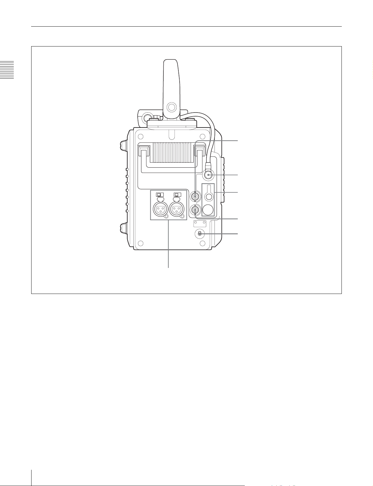
2-1-4 Connector Panel
Chapter 2 Names and Functions of Parts
1 TC IN connector
2 CTRL PANEL connector
3 EARPHONES jack and
LEVEL knob
6 AUDIO INPUT CH-1 and CH-2 connectors and input selection switches
a TC IN (timecode input) connector (BNC type)
Connect to the timecode output connector of an external
device such as a timecode generator or VTR. Use this
connector when locking the internal timecode generator to
external timecode.
b CTRL (control) PANEL connector
Connect the control panel. You can remove the short cable
connected when the SRW-1 is shipped from the factory
and replace it with the supplied extension cable.
For details, see 3-1-2 “Using the Control Panel Extension
Cable” (page 23).
c EARPHONES jack (stereo minijack) and LEVEL
knob
Use this connector to attach earphones or stereo
headphones equipped with a stereo miniplug, for use in
monitoring audio during recording and playback. Adjust
the audio level with the LEVEL knob.
4 TC OUT connector
5 POWER ON/OFF switch
A warning tone is output to the earphones/headphones
when a warning is lit on the control panel display.
d TC OUT (timecode output) connector (BNC type)
Connect to the timecode input connector of an external
device such as a timecode reader or VTR.
The timecode output is determined by the setting of
OTHERS (MAIN) >TC OUT in the TC Setup menu as
follows.
TCG (timecode generator): Timecode generated by the
timecode generator is output, delayed by 1 frame.
(This maintains synchronization with the output
video).
AUTO: During recording (including E-E mode), timecode
generated by the timecode generator is output, delayed
by 1 frame. (This maintains synchronization with the
output video).
During playback, the LTC signal read from the tape is
output.
16
2-1 SRW-1

THRU: Timecode input to the TC IN connector is through
output.
TCG (No Delay): Timecode generated by the timecode
generator is output, with no delay. (The timecode is
out of synchronization with the output video, being 1
frame in advance of the video.) Select this setting
when you want to synchronize other devices, using the
timecode generator of this unit as the master.
e POWER ON/OFF switch
When the SRPC-1 power is on, push this switch up to the
ON side to power the SRW-1 on. To power the SRW-1 off,
push the switch down to the OFF side.
Normally leave this switch on the ON side since the SRW1 is powered on and off automatically by the SRPC-1
POWER ON/OFF switch.
f AUDIO INPUT CH-1 and CH-2 (analog audio
input channels 1 and 2) connectors (XLR 3-pin,
female) and input selection switches
These connectors allow up to two analog audio signals to
be input from microphones and other external audio
devices.
Set the input selection switches as follows, depending on
the type and level of the input audio.
LINE: For line input
MIC: For microphone input
+48V ON: For input from microphones with external
power supply
Chapter 2 Names and Functions of Parts
2-1 SRW-1
17

2-2 SRPC-1
When optional HKSR-101 installed
Chapter 2 Names and Functions of Parts
1 Recorder connector
2 Lock lever
3 Release knob
4 B attery attachment
section
5 AUDIO INPUT CH-3 and
CH-4 connectors and input
selection switches
6 MONITOR OUT L and R
connectors
7 AES/EBU INPUT CH7/8 and CH9/10
connectors
8 AES/EBU OUTPUT CH1-12 connector
w; CAMERA connector
9 Assist lever
0 EARPHONES jack and
LEVEL knob
qa HD SDI OUT A and B
connectors
qs HD SDI IN A and B connectors
qd MONITOR OUT HD SDI
and SD SDI connectors
qf REF IN HD and SD connectors
qg POWER ON/OFF switch
qh REMOTE IN connector
qj CAMERA REMOTE IN
connector
qk EXT DC SELECT switch
ql DC IN connector
a Recorder connector
Connect the SRW-1 HD Portable Digital Recorder.
b Lock lever
After joining the SRW-1 and SRPC-1, rotate this lever to
lock the joint.
c Release knob
When separating the joined SRW-1 and SRPC-1, rotate the
assist lever while pulling out this knob.
Note
Once you have joined the SRW-1 and SRPC-1, do not pull
out the release knob except when you want to detach the
SRW-1 from the SRPC-1 because doing so results in
separation of these units.
d Battery attachment section
Attach a BP-GL95/IL75 Battery Pack or AC-DN10/DN2B
AC Adaptor.
18
2-2 SRPC-1
For details, see 3-4 “Power Supply Preparations” (page
32).
e AUDIO INPUT CH-3 and CH-4 (analog audio
input channels 3 and 4) connectors (XLR 3-pin,
female) and input selection switches
These connectors allow up to two analog audio signals to
be input.
Set the input selection switches as follows, depending on
the type and level of the input audio.
LINE: For line input
MIC: For microphone input
+48V ON: For input from microphones with external
power supply
f MONITOR OUT (audio monitor output) L and R
connectors (XLR 3-pin, male)
Output audio monitor signals.

g AES/EBU INPUT CH7/8 and CH9/10 (digital
audio input channels 7/8 and 9/10) connectors
(BNC type)
These connectors allow up to four AES/EBU format
digital audio signals to be input.
Note
The AES/EBU signals must be locked to the video signal.
h AES/EBU OUTPUT CH1-12 (digital audio output
channels 1 to 12) connector (D-sub 15-pin)
Outputs up to 12 channels of AES/EBU format digital
audio signals.
This connector is specially designed for this system. For
details, refer to the Maintenance Manual Volume 1.
i Assist lever
Use this lever when joining or separating the SRW-1 and
SRPC-1.
n REF IN (reference signal input) HD and SD
connectors (BNC type)
Input a reference video signal with the correct frame
frequency.
HD connector: As an HD reference video signal, input a
tri-level bipolar sync signal.
SD connector: As an SD reference video signal, input a
video signal with a chroma burst signal (VBS) or black
and white video signal (VS).
When carrying out recording, set REFERENCE >MODE
in the SYSTEM Setup menu to “Input” so that the system
is synchronized with the input video signal.
To record the input video signal in synchronization with an
HD reference video signal, input an HD reference video
signal of the same phase as the input video signal.
Note
When using a reference video signal, its field frequency
must correspond to the system frame frequency set with
FORMAT >FRAME in the SYSTEM Setup menu.
Chapter 2 Names and Functions of Parts
j EARPHONES jack (stereo minijack) and LEVEL
knob
Use this connector to attach earphones or stereo
headphones equipped with a stereo miniplug, for use in
monitoring audio during recording and playback. Adjust
the audio level with the LEVEL knob.
A warning tone is output to the earphones/headphones
when a warning is lit on the control panel display.
k HD SDI OUT A and B connectors (BNC type)
Output HD SDI video and audio signals.
When the signal format is 4:2:2, the signals are output
from the “A” connector.
l HD SDI IN A and B connectors (BNC type)
Input HD SDI video and audio signals.
When the signal format is 4:2:2, input the signals to the
“A” connector.
m MONITOR OUT (video monitor output) HD SDI
and SD SDI connectors (BNC type)
Output SDI video and audio signals for monitoring.
HD SDI connector: Outputs HD SDI video and audio
signals for monitoring.
The PD(MON) item in the VIDEO Setup menu (see
page 45) allows you to select whether pull-down
conversion of this output is performed or not.
SD SDI connector: Outputs SD SDI video and audio
signals for monitoring.
Regardless of signal format settings, these connectors
always output signals in 4:2:2 format.
VTR operating status and timecode can be superimposed
on the output (see the CHAR(MON) item in the TC Setup
menu (page 43)).
o POWER ON/OFF switch
Powers the SRPC-1 on when pushed up to the ON side. To
power the SRPC-1 off, push the switch down to the OFF
side.
When the SRW-1 is joined to the SRPC-1, this switch
powers both the SRW-1 and SRPC-1 on and off.
p REMOTE IN (remote control input) connector (9-
pin)
Reserved for future expansion. Currently not used.
q CAMERA REMOTE IN (remote control input)
connector (8-pin)
When the optional HKSR-101 Optical Interface Unit is
installed, you can connect an RM-B750/B150 Remote
Control Unit to this connector.
r EXT DC SELECT (external power selection)
switch
Select the operating mode when an external power supply
is connected.
AUTO: Normally use the external power supply
connected to the DC IN connector, but when its
voltage declines, automatically switch to the power
supply attached to the battery attachment section.
EXT (external): Always use only the external power
supply connected to the DC IN connector.
s DC IN connector (XLR 4-pin, male)
When using the optional AC-550/DN2B/DN10 AC
Adaptor to connect to an AC power source, connect the
DC power cord of the adaptor to this connector.
Use only the DC power cord supplied with the AC adapter.
2-2 SRPC-1
19

t CAMERA connector (optical-fiber connector)
(when HKSR-101 installed)
Connect the HDC-F950 HD Color Video Camera by FC2PD50/PD250 Optical-Fiber Cable (optional).
A single optical-fiber cable can send and receive audio and
control signals multiplexed into video signals.
Chapter 2 Names and Functions of Parts
Refer to the HKSR-101 Installation Manual for
information about installing the HKSR-101.
Notes
• Power cannot be supplied from this unit to a camera over
optical-fiber cable.
• Communications errors can occur if dust accumulates on
the surface of the connector of the optical-fiber cable.
Always clean the CAMERA connector before use.
Whenever the CAMERA connector is not in use, always
cover it with the cap supplied with the HKSR-101.
Refer to the HKSR-101 Installation Manual for
information about cleaning the optical-fiber connector.
20
2-2 SRPC-1

3-1 Assembly
Preparations
Chapter
3
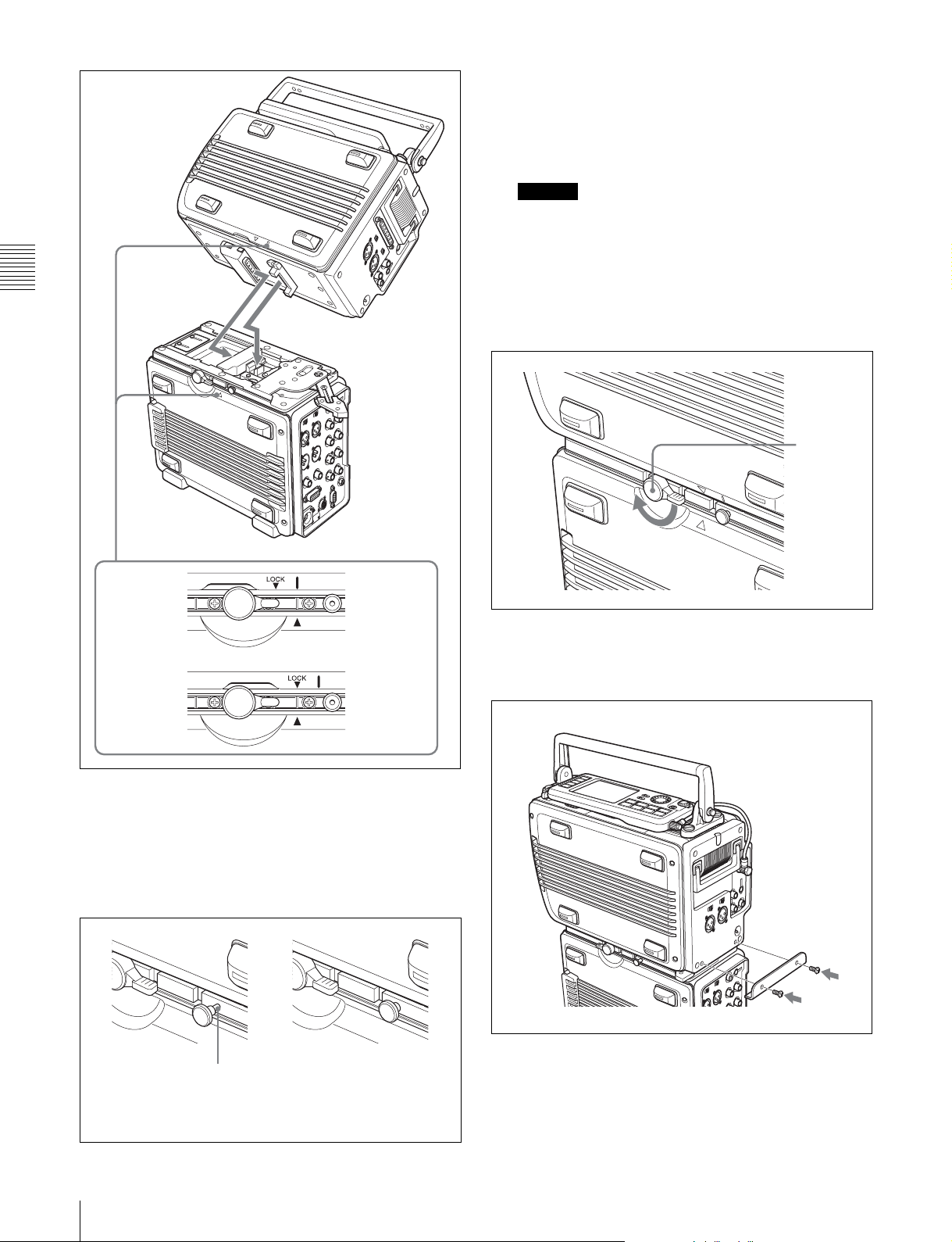
3-1-1 Joining the SRW-1 and SRPC-1
When using the optional HKSR-101 Optical Interface
Unit, refer to the HKSR-101 Installation Manual.
To mount the SRW-1 on the SRPC-1, proceed as follows.
1
Place the SRPC-1 on a flat, stable surface of a bench,
table or the like.
2
Rotate the lock lever counterclockwise (see the figure
for step 3) until it is almost horizontal.
3
Move the assist lever to the unlock position (rotate it in
the direction of the arrow as far as it will go).
Lock lever
Assist lever
Note
If the top handle is detached from the SRW-1, grasp
the side handle with one hand and mount the SRW-1
while supporting it with your other hand.
4
Grasp the top handle of the SRW-1, align the mark on
the SRW-1 with the v mark on the SRPC-1 (see “To
release” in the following figure), and then place the
SRW-1 on the top of the SRPC-1.
3-1 Assembly
21
Next, by attempting to rotate the assist lever again to
the lock position, check to be sure that now the assist
lever will not go beyond half the way and that the
SRW-1 keeps joined to the SRPC-1.
Caution
The SRW-1 and SRPC-1 are not properly joined
unless the release knob is all the way in. They may
come apart, or the SRW-1 may fall off.
6
Chapter 3 Preparations
Rotate the lock lever on the side panel of the SRPC-1
in the direction of the arrow to lock the joint between
the SRPC-1 and SRW-1.
Lock lever
To release
To lock
5
Rotate the assist lever back to its original (lock)
SRW-1 side
SRPC-1 side
SRW-1 side
SRPC-1 side
position to align the LOCK V mark on the SRW-1
with the v mark on the SRPC-1. (See “To lock” in the
previous figure.)
When you do this, check to be sure that the release
knob (see the following figure) is all the way in.
7
Remove the two screws from the holes on the SRW-1,
and use these two screws to mount the supplied assist
lever holding bracket on the SRW-1.
Assist lever
holding bracket
Screws (×2)
22
Release knob is
not all the way in.
3-1 Assembly
This part is visible.
Release knob is
all the way in.
To detach the SRW-1 from the SRPC-1
1
Place the joined SRPC-1 and SRW-1 on a flat, stable
surface of a bench, table or the like.
2
Unscrew the assist lever holding bracket from the
body of the SRW-1.
3
Rotate the lock lever on the side panel of the SRPC-1
in the direction of the arrow to unlock the joint
between the SRPC-1 and SRW-1.
Lock lever
4
While pulling out the release knob on the side panel of
the SRPC-1, rotate the assist lever in the direction of
arrow and then slide the SRW-1.
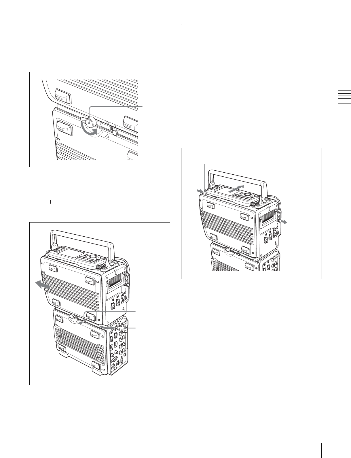
3-1-2 Using the Control Panel
Extension Cable
When they are shipped from the factory, the control panel
and SRW-1 are connected by a short cable. You can
replace this cable with the supplied extension cable, which
allows you to use the control panel apart from the SRW-1.
Proceed as follows.
1
Disconnect the short cable from the CTRL PANEL
connector on the SRW-1. (See the following figure.)
2
While pressing the lock release button next to the
control panel, slide the control panel in the direction of
the arrow in the figure to separate the control panel
from the SRW-1 body.
Lock release button (for control panel)
Chapter 3 Preparations
The mark on the SRW-1 is aligned with the v mark
on the SRPC-1. (See “To release” in the figure on
page 22.)
Release knob
Assist lever
Remove cable
3
Remove the cable from the control panel and replace it
with the extension cable.
4
Connect the extension cable to the CTRL PANEL
connector on the SRW-1.
5
Lift the SRW-1 off the SRPC-1.
6
Move the assist lever to the lock position.
3-1 Assembly
23
 Loading...