

Sony SRFHM-03-V Service manual

SRF-HM03V
SERVICE MANUAL
Ver 1.0 2004.04
SPECIFICATIONS
Time display: 12-hour system
Frequency range:
Band Range Channel step
TV 2 - 13 ch 1 channel
WEATHER 1 - 7 ch 1 channel
FM 87.5 - 108 MHz 0.1 MHz
AM 530 - 1 710 kHz 10 kHz
Headphone type: Dynamic
Power output: 7 mW + 7 mW (at 10 % harmonic distortion)
Power requirements: 1.5V DC, one size AAA (R03) battery
Mass: Approx. 156 g (5.6 oz) incl. a battery
Supplied accessories: Operating instructions
Design
and specifications are subject to change without notice.
531 - 1 710 kHz 9 kHz
US Model
Battery Life (Approx. hours) (JEITA*)
TV WEATHER FM AM
Sony alkaline size AAA (LR03) battery 33 33 37 57
Sony size AAA (R03) battery 14 14 16 26
* Measured by JEITA (Japan Electronics and Information Technology
Industries Association) standards.
The actual battery life may vary depending on the circumstance of the
unit.
PLL SYNTHESIZED HEADPHONE RADIO
9-877-737-01 Sony Corporation
2004D05-1 Personal Audio Company
© 2004.04 Published by Sony Engineering Corporation
TV/WEATHER/FM STEREO/AM

SRF-HM03V
TABLE OF CONTENTS
1. GENERAL ................................................................... 3
2. DISASSEMBLY
2-1. Disassembly Flow ........................................................... 4
2-2. POWER Board ................................................................ 4
2-3. Cable Setting ................................................................... 5
2-4. MICON Board, MAIN Board......................................... 5
2-5. Putting the Sheet (A)....................................................... 6
3. ELECTRICAL ADJUSTMENTS......................... 7
4. DIAGRAMS
4-1. Note for Printed Wiring Boards
and Schematic Diagram .................................................. 8
4-2. Schematic Diagram ......................................................... 9
4-3. Printed Wiring Boards – MAIN/POWER Boards –...... 10
4-4. Printed Wiring Board – MICON Board – ..................... 11
5. EXPLODED VIEWS
5-1. Cabinet (L) Section ......................................................... 14
5-2. Cabinet (R) Section......................................................... 15
5-3. Board Section .................................................................. 16
6. ELECTRICAL PARTS LIST ............................... 17
Notes on chip component replacement
•Never reuse a disconnected chip component.
• Notice that the minus side of a tantalum capacitor may be damaged by heat.
2
SECTION 1
GENERAL
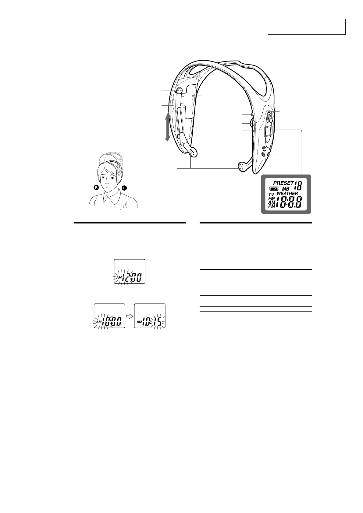
L (Left)
SRF-HM03V
This section is extracted from
instruction manual.
POWER ON/OFF
Light reflector (L)
This reflector
reflects car lights
at night for your
safety.
A
Driver Unit
1
There is a tactile dot beside volume to show the
*
direction to turn up the volume.
2
*
The TUNE + button has a tactile dot.
Setting the Clock
The clock time display of this unit is a 12-hour system.
When the battery is first installed, AM 12:00 flashes in the display.
1
Set POWER to OFF to turn off the power.
2
Hold down MEGA BASS/CLOCK for more than 2 seconds
until AM 12 starts flashing.
Battery
compartment lid
TV/WB/FM SENS
DX/LOCAL
Light reflector (R)
MEGA BASS/CLOCK ENTER
VOL*
1
R (Right)
TUNE +*
MODEBAND
Display
Wearing the Headphone
Radio
(See fig A)
1
Wear the L side driver unit in your left ear and the R side in your
right ear as illustrated.
2
Adjust the position of the driver units for a comfortable fit.
2
/—
3
Press TUNE + or – to adjust the hour, then press MEGA BASS/
CLOCK.
If you hold down TUNE + or —, the digit changes rapidly.
AM 12:00 = midnight, PM 12:00 = noon.
4
Repeat step 3 above to adjust the minute.
: starts flashing and the clock starts operating.
To set the current time exactly to the second, adjust the minute and then press
MEGA BASS/CLOCK to synchronize with a time signal (such as the
telephone time signal).
Note
If you do not press TUNE + or —, or MEGA BASS/CLOCK within one minute,
the clock setting mode will be canceled.
Changing AM Channel Step
The AM channel step differs depending on areas. The channel step of this unit is
factory-set to 10 kHz. Change the settings as shown below to be able to listen to
the radio.
Area Channel step
North and South American countries 10 kHz
Other countries 9 kHz
Note
When the AM channel step is changed, only the preset stations on the AM band
will be initialized.
1
Set POWER to OFF to turn off the power.
2
While holding down MODE, hold down TUNE + or – for more
than 5 seconds.
The channel step will change and 9 kHz (or 10 kHz) will flash for 3
seconds in the display.
If you proceed to step 2 again, the channel step changes again.
3
SRF-HM03V
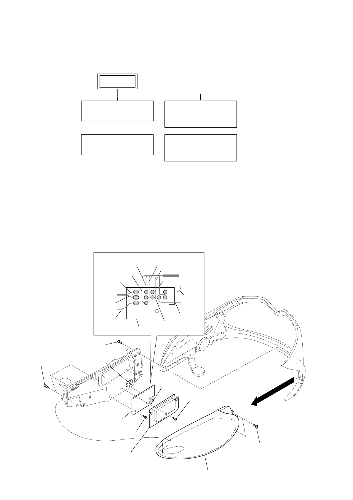
• This set can be disassembled in the order shown below.
2-1. DISASSEMBLY FLOW
SET
SECTION 2
DISASSEMBLY
2-2. POWER BOARD
(Page 4)
2-3. CABLE SETTING
(Page 5)
Note: Follow the disassembly procedure in the numerical order given.
2-2. POWER BOARD
8
Remove the eleven solders.
green
blue
blue
2-4. MICON BOARD,
MAIN BOARD
(Page 5)
2-5. PUTTING THE
SHEET (A)
(Page 6)
black
red
natural
black
red
POWER board
1
six screws
(1.7)
4
three screws
(B1.4)
Note: When installing the POWER board, fit the knob and switch (S401).
knob
0
POWER board
9
7
screw (B1.4)
lid (PWB BATT)
yerrow
S401
white
gray
6
screw (B1.4)
5
cabinet assy front (L)
2
3
two screws
(1.7)
4
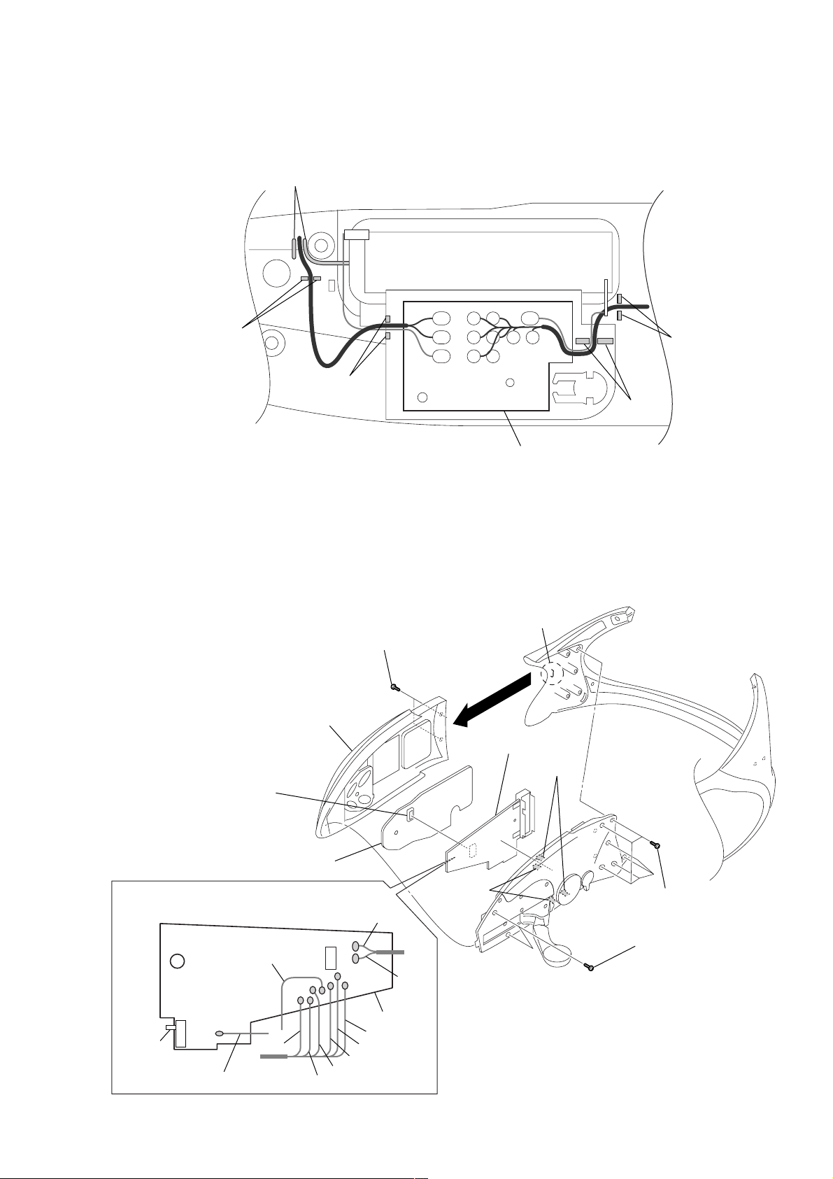
2-3. CABLE SETTING
t
Note: When installing the POWER board, set the cables as shown figure.
slit
SRF-HM03V
slit
slit
2-4. MICON BOARD, MAIN BOARD
3
6
cabinet assy front (R)
7
connector
(CN301)
two screws
(1.7)
2
qs
MAIN board
POWER board
5
claw
q;
two claws
sli
slit
8
MICON board
9
Remove the ten solders.
blue
white
MAIN board
S1
gray
Note: When installing the MAIN board, fit the knob and switch (S1).
blue
yerrow
natural
green
black
red
qa
black
two claws
1
six screws
(1.7)
4
two screws
(B1.4)
5

SRF-HM03V
2-5. PUTTING THE SHEET (A)
sheet (A)
MICON board
leaf (UCOM), copper
6
 Loading...