

Sony SRFFQ-9 Service manual
SRF-FQ9
SERVICE MANUAL
Ver 1.1 1999. 06
SPECIFICATIONS
US Model
Canadian Model
E Model
Notes on chip component replacement
•Never reuse a disconnected chip component.
•Notice that the minus side of a tantalum capacitor may
be damaged by heat.
MICROFILM
FM STEREO/AM RADIO

SECTION 1
GENERAL
This section is extracted from
instruction manual.
– 2 –
SECTION 2
)
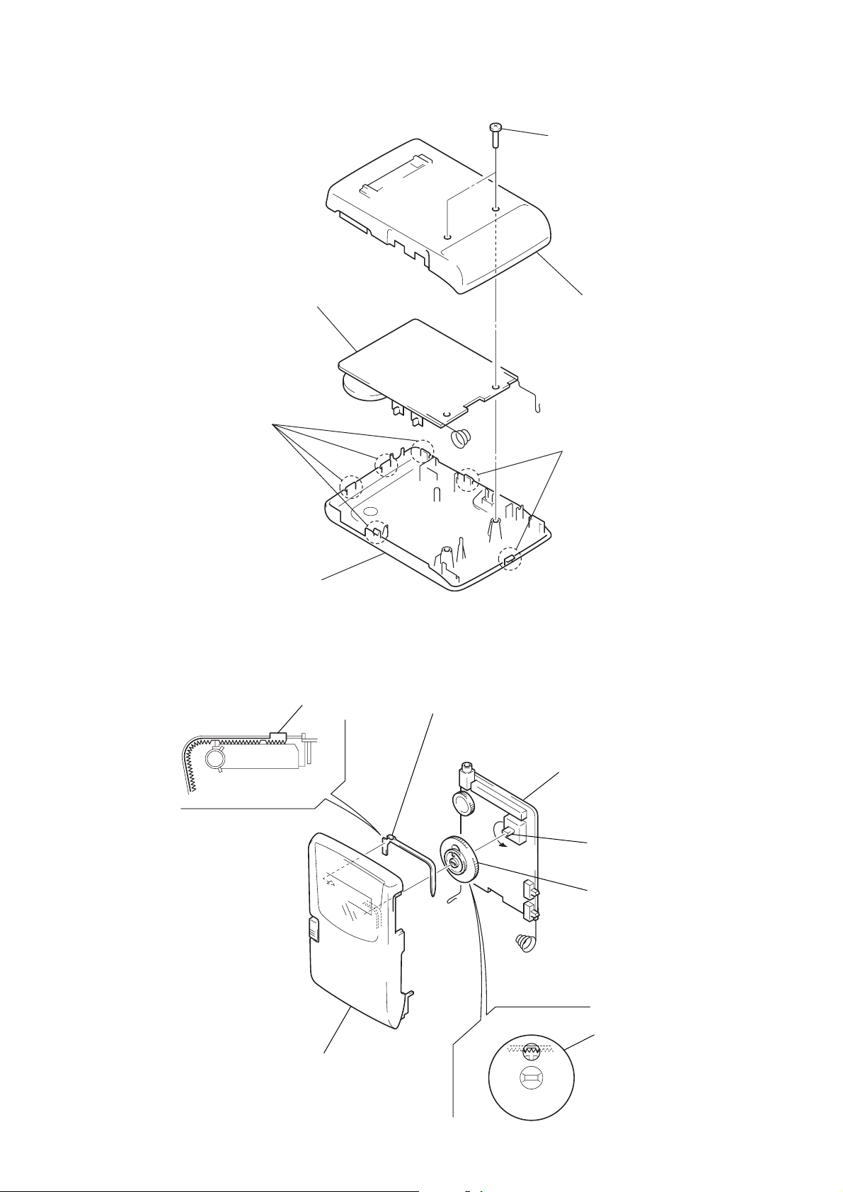
DISASSEMBLY
Note: Follow the disassembly procedure in the numerical order given.
MAIN BOARD
2
four claws
4
main board
1
two screws
(P2
2
×
8)
3
cabinet (rear
two claws
5
cabinet (front)
DIAL POINTER SETTING
Note: Follow the assembly procedure in the numerical order given.
pointer
fig.
A
1
Mount the pointer as
shown in the figure
A
.
4
main board
3
Turn CV1 fully in the
arrow direction.
2
Mount the knob (TUNE)
as shown in the figure
B
.
cabinet (front)
– 3 –
fig.
knob (TUNE)
B
 Loading...