

Page 1
SRF-DR2000
SERVICE MANUAL
Ver 1.0 1998.03
SPECIFICATIONS
Frequency range 87.5 – 108MHz
FM multiplex DARC type
64 x 132 FSTN LCD display
Output 2 jack (stereo minijack)
Power output 8 mW + 8 mW (at 10% harmonic distortion)
Power requirements DC 3V, two R6 (size AA) /LR6 batteries
Auto power off function Approx. 120 minutes
Dimensions 116 x 70.5 x 28 mm (w/h/d)
(Approx. 4 5/8 x 2 7/8 x 11/8 inches) not incl.
projecting parts and controls
Mass Approx. 150 g (5.3 oz) incl. batteries
Supplied Accessories Stereo headphones (1)
French Model
Design and specifications are subject to change without notice.
FM DATA RECEIVER
MICROFILM
Page 2
TABLE OF CONTENTS
Specifications ........................................................................... 1
1. GENERAL ...................................................................... 2
2. DISASSEMBLY
2-1. Cabinet (Rear) Removal ............................................. 6
2-2. Main Board Removal ................................................. 6
2-3. MICOM Board, LCD1 Removal ................................ 7
3. ELECTRICAL ADJUSTMENTS...........................8
SECTION 1
GENERAL
4. DIAGRAMS
4-1. Explanation of IC Terminals....................................... 9
4-2. Block Diagrams ........................................................ 13
4-3. Printed Wiring Boards (Main Section) ..................... 15
4-4. Schematic Diagram (Main Section) ......................... 17
4-5. Printed Wiring Boards (MICOM Section)................ 19
4-6. Schematic Diagram (MICOM Section) .................... 21
5. EXPLODED VIEW ................................................ 24
6. ELECTRICAL PARTS LIST ................................ 25
This section is extracted from
instruction manual.
– 2 –
Page 3
– 3 –
Page 4
– 4 –
Page 5
– 5 –
Page 6
SECTION 2
DISASSEMBLY
r
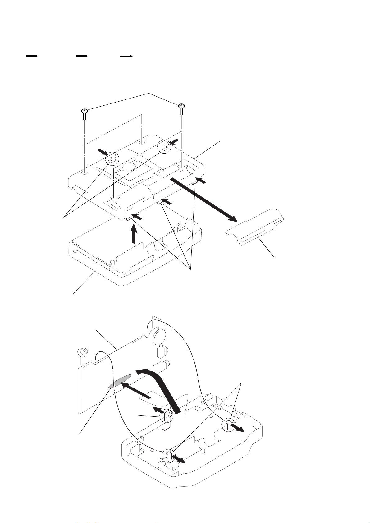
The equipment can be removed using the following procedure.
Set
Cabinet (Rear)
Main board
Note : Follow the disassembly procedure in the numerical order given.
2-1. CABINET (REAR) REMOVAL
MICOM board, LCD1
2
Screws (1.7x10)
7
Claws
Cabinet (Front)
2-2. MAIN BOARD REMOVAL
8
3
4
6
Cabinet (Rear)
5
1
Lid, battery case
Claws
Main board
5
Removal solder
Claw
1
4
Claws
3
2
– 6 –
Page 7
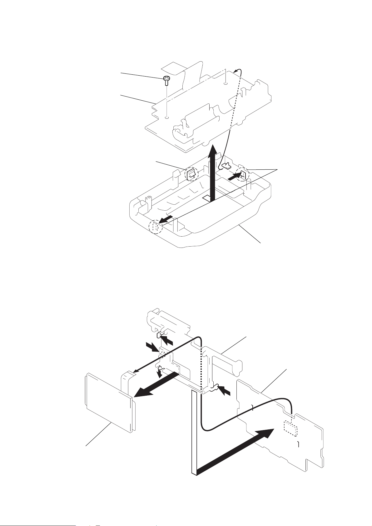
2-3. MICOM BOARD, LCD1 REMOVAL
s
1
Screws (1.7x5)
MICOM board
Claw
4
Claw
3
2
5
6
Cabinet (Front)
Holder (LCD)
9
MICOM board
0
!¡
7
LCD1
– 7 –
8
Page 8

SECTION 3
r
t
ELECTRICAL ADJUSTMENTS
FM Section
Setting :
VOLUME : Maximum
FM RF signal
generator
µ
0.01 F
TP FM IN
(BPF401
1
pin)
22.5kHz frequency
deviation by 400Hz signal.
Output level :
as low as possible
16
level mete
Ω
set
phones jack
• Repeat the procedures in each adjustment several times, and the
tracking adjustments should be finally the trimmer capacitors.
FM IF ALIGNMENT
Adjust for a maximum reading on level meter.
T401 10.7MHz
FM TRACKING ADJUSTMENT
Adjust for a maximum reading on level meter.
CT402 98.0MHz
Adjustments Location :
[MAIN BOARD]
(Side A)
CT402 : FM Tracking Adjustmen
T401 : FM IF Alignment
RV401 : VCO Adjustment
FM VCO Adjustment
Procedure :
[MAIN BOARD] (Side A)
DC5V
frequency counter
6
IC403
10
2.4k
0.01µF
Servicing tool
5
1
Ω
2SK193-E
S
R428
10
1M
µ
F
1pF
Ω
R418
RV401
76K
1. Connect a capacitor (10µF) between pin 1 of IC403 and ground.
2. Adjust R V401 for 76.2kHz – 75.8kHz reading on the frequency
counter.
– 8 –
Page 9

SECTION 4
DIAGRAMS
4-1. EXPLANATION OF IC TERMINALS
IC101 MSM65587 (MAIN SYSTEM CONTROL)
Pin No. Pin name I/O Description
1 MUTE O Mute signal output.
2 BEEP O Beep signal output.
3 DEC INT I Interrupt signal input from decoder IC (IC204).
4 BUSY I Busy signal input from DE-SCRAMBLE MICOM (IC301).
5 F3 I Function 3 key input.
6 F5 I Function 5 key input.
7 F4 I Function 4 key input.
8 (–) I Tune (–) key input.
9 VDD – Power supply (+3V).
10 VREF – Voltage reference terminal.
11 AGND – Ground for analog.
12 - 15 AI0 - AI3 – Not used (Ground connect).
16 GND – Ground.
17 VDD – Power supply (+3V).
18 READY PLL I Input PLL ready OK signal.
19 REQ PLL O PLL communication request output terminal.
20 DATA PLL O PLL serial data output terminal.
21 CLOCK PLL O PLL serial clock output terminal.
22 DI EEP I Data read input from EEPROM.
23 DO EEP O Data write output to EEPROM.
24 CLK EEP O Clock output to EEPROM.
25 CS EEP O Chip select output to EEPROM.
26 F2 I Function 2 key input.
27 DISPLAY I Display (FM data) key input.
28 SAVE I Save key input.
29 F1 I Function 1 key input.
30 ENTER I Enter key input.
31 BACK I Back key input.
32 FLA CLK – Not used (“H” level).
33 FLA DAT – Not used (“H” level).
34 RES I System reset terminal.
35 NMI Not used (“H” level).
36 EA I Internal memory selection. “H” : Active
37 VDD – Power supply (+3V).
38 OSC0 I Main system clock oscillator (4.9152 MHz).
39 OSS1 O Main system clock oscillator (4.9152 MHz).
40 GND – Ground.
41 OSC CNT O Clock oscillator control.
42 - 46 – Not used (Open).
47 RD O External memory read output. “L” : Reading
48 WR O External memory write output. “L” : Writing
49 – Not used (Open).
50 ALE O Address latch signal output to external memory.
51 - 58 D0 - D7 I/O Address / data bus input / output to external memory.
59 - 65 A8 - A14 O Address bus output to external memory.
66 – Not used (Open).
67 VDD – Power supply (+3V).
68 GND – Ground.
______
____
___
_____
___
___
– 9 –
Page 10

Pin No. Pin name I/O Description
69 A15 O Address bus output to external memory.
70 A16 O Address bus output to external memory.
71, 72 – Not used (Open).
73 CS DEC O Chip select output to decoder (IC204).
74 CS RAM O Chip select output to RAM (IC202).
75 CS ROM O Chip select output to ROM (IC203).
76 DEC RES O Reset signal output to decoder (IC204).
77 - 78 – Not used (Open).
81 RESET O Reset signal output to DE-SCRAMBLE MICOM (IC301).
82 DD RDY I De-scramble end signal input.
83 CLK O Clock output to DE-SCRAMBLE MICOM (IC301).
84 DI O Data output to DE-SCRAMBLE MICOM (IC301).
85 DO I Data input from DE-SCRAMBLE MICOM (IC301).
86 INT O De-scramble request signal output.
87 POWER O Radio power supply ON/OFF control. “H” : Radio power ON
88 (+) I Tune (+) key input.
89 SRAM CHECK I SRAM check terminal.
90 A0 LCD O Communications with LCD module.
91 CS LCD O Communications with LCD module.
92 RES LCD O Communications with LCD module.
93 VDD – Power supply (+3V).
94 GND – Ground.
95 VDET I Low voltage (1.9V) DET. “L” : power OFF
96 POWER SW I Power ON/OFF key input.
97 EXT (IN) I External (Beep) signal input.
98 DATA LCD O Serial data output to LCD module.
99 EXT (OUT) O External (Beep) signal output.
100 SCL LCD O Serial clock output to LCD module.
_______
– 10 –
Page 11

IC204 (MSM9553) DECODER
Pin No. Pin name I/O Description
1 MON – Not used (Open).
2 ADET IN I Analog signal input for test (connected ground).
3 AVDD – Power supply terminal for analog (+3.5V).
4 AGND – Ground terminal for analog (ground).
5 SG O Reference voltage terminal for analog.
6 AIN I FM multiplex signal input terminal.
7 XOUTC – Not used (Open).
8 - 14 MOUT0 - MOUT6 – Not used (Open).
15 INT O interrupt signal output to MICOM (IC101).
16 WR I Write signal input terminal to internal register.
17 NC – Not used (Open).
18 RD I Ready signal input terminal to internal register.
19 - 26 D0 - D7 I/O Data bus signal input/output terminal to internal register.
27 KGND – Ground terminal for digital.
28 DVDD – Power supply terminal for digital.
29 XTAL1 I Oscillator connection terminal (8.192MHz).
30 XTAL2 O Oscillator connection terminal (8.192MHz).
31 CS I Chip select signal input terminal.
32 XOUT – Not used (Open).
33 - 38 A0 - A5 I Address signal input terminal to internal register.
39 NC – Not used (Open).
40 CLR I Internal register is reset at “L” setting power down status.
41 IORD – Not used (Open).
42 IOWR – Not used (Open).
43,44 NC – Not used (Open).
________
____
___
___
___
____
_____
______
– 11 –
Page 12

IC301 MSM 69231-GS-2K (DE-SCRAMBLE MICOM)
Pin No. Pin name I/O Description
1 – Not used (Open).
2 DO O De-scramble data output.
3 DI I De-scramble data input.
4 CLK I Serial clock input.
5 RESET I Input signal input.
–––––––––––––
6, 7 – Not used (Open).
8 INT Input terminal for external de-scramble request singal.
9 – 13 – Not used (Open).
14 OSC1 O Main system clock oscillator (4.9152MHz).
–––––––––
15 OSC0 I Main system clock oscillator (4.9152MHz).
16 GND – Ground.
17 OSC CONT O Clock oscillator control.
18 – 28 – Not used (Open).
29 EA I Test terminal (Must be connected to VDD).
30 – 38 – Not used (Open).
39 VDD – Power supply (+3.2V).
40 – Not used (Open).
41 DDRDY O De-scramble end signal output to external.
42 BUSY O Busy signal output to external.
––––––––––––––––
––––––––––––
43, 44 – Not used (Open).
IC501 (µPD17015G) DTS MICROCOMPUTER
Pin No. Pin name I/O Description
1 REQ I Communication request signal input.
2 READY O Output communication OK signal output.
3 - 5 PC1 - PC3 – Not used (Open).
6 BEEP – Not used (Open).
7 DATA I PLL data input terminal.
8 CLK I PLL clock input terminal.
9, 10 PA2,PA3 – Not used (Open).
11 CE – Not used (VDD connection).
12 XOUT O Clock oscillator connection terminal.
13 XIN I Clock oscillator connection terminal.
14 VDD – Power supply (+3V).
15 GND – Ground.
16 EO O PLL error output terminal.
17 VREG – Voltage REG terminal.
18 VCOH – Input local oscillator (VCO) output.
19 VCOL – Not used (Open).
20 - 28 LCD8 - LCD0 – Not used (Open).
29 - 32 COM3 - COM0 – Not used (Open).
33 VLCD1 – Not used (Open).
34, 35 CAP1,CAP0 – Not used (Open).
36 VLCD0 – Not used (Open).
37, 38 PB0,PB1 – Not used (Open).
– 12 –
Page 13

4-2. BLOCK DIAGRAM
SRF-DR2000
– 13 – –14 –
• Signal path.
F : FM
J : Multiplex
Page 14

Page 15

4-4. SCHEMATIC DIAGRAM (MAIN SECTION)
p
p
p
r
Refer to page 23 for IC Block Diagrams.
SRF-DR2000
Note:
• All capacitors are in µF unless otherwise noted. pF: µµF
50 WV or less are not indicated except for electrolytics
and tantalums.
• All resistors are in Ω and 1/
specified.
¢
•
• U : B+ Line.
• H : adjustment for repair.
• Power voltage is dc 3 V and fed with regulated dc power
• Voltages and waveforms are dc with respect to ground
• Voltages are taken with a VOM (Input impedance 10 MΩ ).
• Waveforms are taken with a oscilloscope.
• Circled numbers refer to waveforms.
: internal component.
supply from external power voltage jack.
under no-signal (detuned) conditions.
no mark : FM
Voltage variations may be noted due to normal produc-
tion tolerances.
Voltage variations may be noted due to normal produc-
tion tolerances.
4
W or less unless otherwise
• Signal path.
F : FM
J : Multiplex
r
WAVEFORM (MAIN SECTION)
1
1.7Vp-
75kHz
IC501 !™
VOLT/DIV : 0.5 V AC
TIME/DIV : 5 µsec
r
WAVEFORMS (MICOM SECTION)
1
Power failure at
4.9152MHz
IC301 !¢
1.8Vp-p
VOLT/DIV : 0.5V AC
TIME/DIV : 0.1 µsec
2
IC101 #•
2.5Vp-
4.9152MHz
VOLT/DIV : 0.5V AC
TIME/DIV : 0.1µsec
– 17 – – 18 –
3
IC204 #º
2.4Vp-
8.192MHz
VOLT/DIV : 0.5V AC
TIME/DIV : 0.1µsec
Page 16

Page 17

4-6. SCHEMATIC DIAGRAM (MICOM SECTION)
r
Refer to page 18 for Wavforms.
r
Refer to page 23 for IC Block Diagrams.
SRF-DR2000
Note:
• X : parts extracted from the component side.
r
•
• b : Pattern from the side which enables seeing.
(The other layers' patterns are not indicated.)
Caution:
Pattern face side: Parts on the pattern face side seen from
(Conductor Side) the pattern face are indicated.
Parts face side: Parts on the parts face side seen from
(Component Side) the parts face are indicated.
: Through hole.
Note:
• All capacitors are in µF unless otherwise noted. pF: µµF
50 WV or less are not indicated except for electrolytics
and tantalums.
• All resistors are in Ω and 1/
specified.
• U : B+ Line.
• Power voltage is dc 3 V and fed with regulated dc power
supply from external power voltage jack.
4
W or less unless otherwise
• Voltages and waveforms are dc with respect to ground
under no-signal (detuned) conditions.
no mark : FM
( ) : Multiplex
• Voltages are taken with a VOM (Input impedance 10 MΩ ).
Voltage variations may be noted due to normal production tolerances.
• Waveforms are taken with a oscilloscope.
Voltage variations may be noted due to normal production tolerances.
• Circled numbers refer to waveforms.
• Signal path.
J : Multiplex
– 21 – – 22 –
Page 18

SECTION 5
EXPLODED VIEW
r
IC BLOCK DIAGRAMS
IC401 TA8158F (ER)
RF IN
BIAS
RF OUT
MIX IN
GND
RF AMP
1
2
3
4
5
BUFFER
BIAS
OSCILLATOR
POWER SUPPLY
CIRCUIT
IC402 CXA1111N
DET
FILTER
VCC
MUTE
24 23 22 21 20 19 18 17 16 15 14 13
BAND SIGNAL
OUTPUT CIRCUIT
FM.IF
DISCRI
AM.FE
AFCJ
AFCW
RIPPLE
FILTER
EARTH
IF
TUNING
METER
10
9
8
7
6
TUNE
NC
VCC
OSC
OSC MONI
MIX OUT
FM IF
AM.IF
DET.AGC
BAND
AM IF
REGULATOR
IC403 LA3335M
R
DECODER
STEREO
SWITCH
1
IN
IC404 LA4533M
POWER
1
P/SW
IN1
PRE GND
IN2
REF
SWITCH
2
BIAS
3
4
5
L
910
PHASE
COMPALATE
234
FILTER
AMP1
AMP2
M/ST
8
SYNC
DET
FF 1/2FF 90º
VCC
MUTE
CIRCIUT
LAMP
TRIGGER
FF 0º
V.C.O VCO STOP
VCO
10
MT/SW
OUT1
9
8
POWER GND
7
OUT2
6
VCC
GND
STLED
6
7
5
NC
NOTE :
• -XX, -X mean standardized parts, so they
may have some difference from the original
one.
• Items marked “ * ”are not stocked since they
are seldom required for routine service. Some
delay should be anticipated when ordering
these items.
3
2
20
• The mechanical parts with no reference
number in the exploded views are not
supplied.
• Accessories and packing materials are given
in the last of this parts list.
10
LCD1
not supplied
18
6
5
4
17
12
11
13
8
19
7
14
9
15
not supplied
not supplied
FM.FE
1 2 3 4 5 6 7 8 9 10 11 12
EARTH
DISCRI
AM OSC
AFC
FM OSC
REG
FM RF
AM RF
NC
FM IN
EARTH
MIX OUT
18
1
Ref. No. Part No. Description Remark Ref. No. Part No. Description Remark
1 3-930-536-11 PANEL
2 3-930-534-11 CABINET (FRONT)
3 1-762-590-21 SWITCH, RUBBER KEY (MENU)
4 1-762-591-21 SWITCH, RUBBER KEY (POWER)
* 5 A-3663-105-A MICOM BOARD, COMPLETE
6 3-374-079-01 SCREW (1.7X5), TAPPING
* 7 A-3683-003-A MAIN BOARD, COMPLETE
8 3-930-599-01 TERMINAL (-), BATTERY
9 3-930-598-01 TERMINAL (+), BATTERY
* 10 3-930-535-01 HOLDER (LCD)
11 3-936-441-01 CUSHION (BATTERY CASE LID)
12 3-930-591-21 LID, BATTERY CASE
13 3-910-063-01 SCREW (1.7X10)
14 3-930-583-21 CABINET (REAR)
15 3-930-593-21 STAND
* 17 3-698-057-01 STOPPER, B1
18 3-027-525-01 CUSHION
19 3-027-608-01 SPACER (DIA. 3)
20 3-572-550-01 CUSHION (A)
LCD1 1-801-152-11 LCD MODULE
– 23 – – 24 –
Page 19

SECTION 6
ELECTRICAL PARTS LIST
NOTE :
• Due to standardization, replacements in the
parts list may be different from the parts
specified in the diagrams or the components
used on the set.
• -XX, -X mean standardized parts, so they
may have some difference from the original
one.
• RESISTORS
All resistors are in ohms
METAL : Metal-film resistor
METAL OXIDE :Metal oxide-film resistor
F : nonflammable
• Items marked “ * ”are not stocked since
they are seldom required for routine service.
Some delay should be anticipated when
ordering these items.
Ref. No. Part No. Description Remark Ref. No. Part No. Description Remark
* A-3683-003-A MAIN BOARD, COMPLETE
*********************
• SEMICONDUCTORS
In each case, u : µ , for example :
uA.... : µ A.... , uPA.... : µ PA....
uPB.... : µ PB.... , uPC.... : µ PC....
uPD.... : µ PD....
• CAPACITORS
uF : µ F
• COILS
uH : µ H
C435 1-164-346-11 CERAMIC CHIP 1uF 16V
C436 1-163-038-91 CERAMIC CHIP 0.1uF 25V
When indicating parts by reference number, please include the board.
MAIN
3-027-783-01 LEAF (CF), COPPER
< FILTER >
BPF401 1-239-061-11 FILTER, BAND PASS
< CAPACITOR >
C401 1-163-251-11 CERAMIC CHIP 100PF 5% 50V
C402 1-163-220-11 CERAMIC CHIP 3PF 0.25PF 50V
C403 1-163-009-11 CERAMIC CHIP 0.001uF 10% 50V
C404 1-163-227-11 CERAMIC CHIP 10PF 0.5PF 50V
C405 1-163-085-00 CERAMIC CHIP 2PF 50V
C406 1-163-141-00 CERAMIC CHIP 0.001uF 5% 50V
C407 1-163-009-11 CERAMIC CHIP 0.001uF 10% 50V
C408 1-163-141-00 CERAMIC CHIP 0.001uF 5% 50V
C409 1-163-085-00 CERAMIC CHIP 2PF 50V
C410 1-163-141-00 CERAMIC CHIP 0.001uF 5% 50V
C411 1-124-589-11 ELECT 47uF 20% 16V
C412 1-163-021-91 CERAMIC CHIP 0.01uF 10% 50V
C413 1-163-021-91 CERAMIC CHIP 0.01uF 10% 50V
C414 1-163-021-91 CERAMIC CHIP 0.01uF 10% 50V
C416 1-163-021-91 CERAMIC CHIP 0.01uF 10% 50V
C417 1-126-157-11 ELECT 10uF 20% 16V
C418 1-163-021-91 CERAMIC CHIP 0.01uF 10% 50V
C419 1-164-346-11 CERAMIC CHIP 1uF 16V
C420 1-164-346-11 CERAMIC CHIP 1uF 16V
C421 1-163-038-91 CERAMIC CHIP 0.1uF 25V
C422 1-163-037-11 CERAMIC CHIP 0.022uF 10% 25V
C423 1-163-121-00 CERAMIC CHIP 150PF 5% 50V
C424 1-163-133-00 CERAMIC CHIP 470PF 5% 50V
C425 1-126-157-11 ELECT 10uF 20% 16V
C426 1-163-021-91 CERAMIC CHIP 0.01uF 10% 50V
C427 1-163-038-91 CERAMIC CHIP 0.1uF 25V
C428 1-163-275-11 CERAMIC CHIP 0.001uF 5% 50V
C429 1-164-346-11 CERAMIC CHIP 1uF 16V
C430 1-163-023-00 CERAMIC CHIP 0.015uF 5% 50V
C431 1-163-038-91 CERAMIC CHIP 0.1uF 25V
C432 1-163-038-91 CERAMIC CHIP 0.1uF 25V
C433 1-163-023-00 CERAMIC CHIP 0.015uF 5% 50V
C434 1-104-847-11 TANTAL. CHIP 22uF 20% 4V
C437 1-124-584-00 ELECT 100uF 20% 10V
C438 1-163-038-91 CERAMIC CHIP 0.1uF 25V
C439 1-126-382-11 ELECT 100uF 20% 6.3V
C440 1-124-584-00 ELECT 100uF 20% 10V
C442 1-135-201-11 TANTALUM CHIP 10uF 20% 4V
C443 1-164-346-11 CERAMIC CHIP 1uF 16V
C445 1-163-037-11 CERAMIC CHIP 0.022uF 10% 25V
C446 1-163-037-11 CERAMIC CHIP 0.022uF 10% 25V
C501 1-163-021-91 CERAMIC CHIP 0.01uF 10% 50V
C502 1-162-568-11 CERAMIC CHIP 0.33uF 10% 16V
C503 1-163-239-11 CERAMIC CHIP 33PF 5% 50V
C504 1-163-231-11 CERAMIC CHIP 15PF 5% 50V
C505 1-164-346-11 CERAMIC CHIP 1uF 16V
C506 1-163-038-91 CERAMIC CHIP 0.1uF 25V
C507 1-163-009-11 CERAMIC CHIP 0.001uF 10% 50V
C508 1-163-125-00 CERAMIC CHIP 220PF 5% 50V
C601 1-164-346-11 CERAMIC CHIP 1uF 16V
C602 1-163-227-11 CERAMIC CHIP 10PF 0.5PF 50V
C603 1-126-157-11 ELECT 10uF 20% 16V
C604 1-163-038-91 CERAMIC CHIP 0.1uF 25V
C605 1-104-483-11 ELECT 470uF 20% 4V
C606 1-163-141-00 CERAMIC CHIP 0.001uF 5% 50V
C607 1-163-141-00 CERAMIC CHIP 0.001uF 5% 50V
C701 1-163-009-11 CERAMIC CHIP 0.001uF 10% 50V
C702 1-163-009-11 CERAMIC CHIP 0.001uF 10% 50V
C703 1-163-009-11 CERAMIC CHIP 0.001uF 10% 50V
C704 1-163-009-11 CERAMIC CHIP 0.001uF 10% 50V
C705 1-163-021-91 CERAMIC CHIP 0.01uF 10% 50V
C706 1-163-021-91 CERAMIC CHIP 0.01uF 10% 50V
C707 1-135-151-21 TANTALUM CHIP 4.7uF 20% 4V
C708 1-163-021-91 CERAMIC CHIP 0.01uF 10% 50V
C709 1-135-151-21 TANTALUM CHIP 4.7uF 20% 4V
C710 1-163-021-91 CERAMIC CHIP 0.01uF 10% 50V
C711 1-163-021-91 CERAMIC CHIP 0.01uF 10% 50V
< FILTER >
CF401 1-577-572-11 FILTER, CERAMIC
CF402 1-577-574-11 FILTER, CERAMIC
CF403 1-577-574-11 FILTER, CERAMIC
– 25 –
Page 20

MAIN
Ref. No. Part No. Description Remark Ref. No. Part No. Description Remark
< TRIMMER >
CT402 1-141-304-21 CAP, TRIMMER 10PF
< DIODE >
D401 8-713-100-11 DIODE 1T362
D402 8-713-100-11 DIODE 1T362
D601 8-719-988-62 DIODE 1SS355
D602 8-719-977-40 DIODE UDZ-TE-17-13B
D603 8-719-975-40 DIODE RB411D
D604 8-719-975-40 DIODE RB411D
D701 8-719-421-40 DIODE MA77
D702 8-719-421-40 DIODE MA77
D703 8-719-058-24 DIODE RB501V-40TE-17
D704 8-719-058-24 DIODE RB501V-40TE-17
D705 8-719-058-24 DIODE RB501V-40TE-17
D706 8-719-058-24 DIODE RB501V-40TE-17
< IC >
R408 1-216-001-00 METAL CHIP 10 5% 1/10W
R409 1-216-073-00 METAL CHIP 10K 5% 1/10W
R410 1-216-033-00 METAL CHIP 220 5% 1/10W
R411 1-216-081-00 METAL CHIP 22K 5% 1/10W
R412 1-216-089-91 RES,CHIP 47K 5% 1/10W
R413 1-216-065-91 RES,CHIP 4.7K 5% 1/10W
R414 1-216-001-00 METAL CHIP 10 5% 1/10W
R415 1-216-097-91 RES,CHIP 100K 5% 1/10W
R416 1-216-041-00 METAL CHIP 470 5% 1/10W
R417 1-216-001-00 METAL CHIP 10 5% 1/10W
R418 1-216-083-00 METAL CHIP 27K 5% 1/10W
R419 1-216-101-00 METAL CHIP 150K 5% 1/10W
R420 1-216-101-00 METAL CHIP 150K 5% 1/10W
R421 1-216-049-91 RES,CHIP 1K 5% 1/10W
R422 1-216-049-91 RES,CHIP 1K 5% 1/10W
R423 1-216-001-00 METAL CHIP 10 5% 1/10W
R424 1-216-049-91 RES,CHIP 1K 5% 1/10W
R425 1-216-017-91 RES,CHIP 47 5% 1/10W
R426 1-216-049-91 RES,CHIP 1K 5% 1/10W
IC401 8-759-493-45 IC TA8158F(ER)
IC402 8-752-065-30 IC CXA1111N
IC403 8-759-804-98 IC LA3335M
IC404 8-759-802-75 IC LA4533M
IC501 8-759-379-75 IC uPD17015GS-526-GJG-E1
< JACK >
J401 1-563-857-11 JACK, HEADPHONE (2)
J601 1-580-372-11 JACK,DC(POLARITY UNIFIED TYPE)
< COIL >
L201 1-412-002-31 CHIP INDUCTOR 4.7uH
L401 1-410-807-11 INDUCTOR 0.1uH
L402 1-410-730-11 INDUCTOR CHIP 0.12uH
L403 1-411-393-11 COIL, TRAP
< TRANSISTOR >
Q401 8-729-920-38 TRANSISTOR 2SC2059K-N
Q402 8-729-920-38 TRANSISTOR 2SC2059K-N
Q403 8-729-620-06 TRANSISTOR 2SC3052-EF
Q404 8-729-620-06 TRANSISTOR 2SC3052-EF
Q501 8-729-620-06 TRANSISTOR 2SC3052-EF
Q502 8-729-620-06 TRANSISTOR 2SC3052-EF
Q601 8-729-620-06 TRANSISTOR 2SC3052-EF
Q602 8-729-620-06 TRANSISTOR 2SC3052-EF
Q603 8-729-800-71 TRANSISTOR 2SB815B7-TB
Q604 8-729-620-06 TRANSISTOR 2SC3052-EF
Q701 8-729-920-38 TRANSISTOR 2SC2059K-N
Q702 8-729-620-06 TRANSISTOR 2SC3052-EF
(DC IN 3V)
R427 1-216-001-00 METAL CHIP 10 5% 1/10W
R428 1-216-101-00 METAL CHIP 150K 5% 1/10W
R429 1-216-045-00 METAL CHIP 680 5% 1/10W
R430 1-216-049-91 RES,CHIP 1K 5% 1/10W
R431 1-216-001-00 METAL CHIP 10 5% 1/10W
R432 1-216-001-00 METAL CHIP 10 5% 1/10W
R451 1-216-113-00 METAL CHIP 470K 5% 1/10W
R452 1-216-113-00 METAL CHIP 470K 5% 1/10W
R501 1-216-073-00 METAL CHIP 10K 5% 1/10W
R502 1-216-073-00 METAL CHIP 10K 5% 1/10W
R503 1-216-097-91 RES,CHIP 100K 5% 1/10W
R504 1-216-097-91 RES,CHIP 100K 5% 1/10W
R505 1-216-073-00 METAL CHIP 10K 5% 1/10W
R506 1-216-073-00 METAL CHIP 10K 5% 1/10W
R507 1-216-097-91 RES,CHIP 100K 5% 1/10W
R508 1-216-073-00 METAL CHIP 10K 5% 1/10W
R509 1-216-001-00 METAL CHIP 10 5% 1/10W
R601 1-216-017-91 RES,CHIP 47 5% 1/10W
R602 1-216-049-91 RES,CHIP 1K 5% 1/10W
R604 1-216-089-91 RES,CHIP 47K 5% 1/10W
R605 1-216-097-91 RES,CHIP 100K 5% 1/10W
R606 1-216-089-91 RES,CHIP 47K 5% 1/10W
R607 1-216-057-00 METAL CHIP 2.2K 5% 1/10W
R608 1-216-097-91 RES,CHIP 100K 5% 1/10W
R609 1-216-113-00 METAL CHIP 470K 5% 1/10W
R701 1-216-049-91 RES,CHIP 1K 5% 1/10W
R702 1-216-097-91 RES,CHIP 100K 5% 1/10W
R703 1-216-057-00 METAL CHIP 2.2K 5% 1/10W
R704 1-216-081-00 METAL CHIP 22K 5% 1/10W
R705 1-216-097-91 RES,CHIP 100K 5% 1/10W
< RESISTOR >
R401 1-216-065-91 RES,CHIP 4.7K 5% 1/10W
R402 1-216-097-91 RES,CHIP 100K 5% 1/10W
R403 1-216-001-00 METAL CHIP 10 5% 1/10W
R404 1-216-089-91 RES,CHIP 47K 5% 1/10W
R405 1-216-033-00 METAL CHIP 220 5% 1/10W
R406 1-216-097-91 RES,CHIP 100K 5% 1/10W
R706 1-216-045-00 METAL CHIP 680 5% 1/10W
R707 1-216-073-00 METAL CHIP 10K 5% 1/10W
R708 1-216-097-91 RES,CHIP 100K 5% 1/10W
R709 1-216-081-00 METAL CHIP 22K 5% 1/10W
R710 1-216-073-00 METAL CHIP 10K 5% 1/10W
R711 1-216-025-91 RES,CHIP 100 5% 1/10W
– 26 –
Page 21

MAIN
Ref. No. Part No. Description Remark Ref. No. Part No. Description Remark
< VARIABLE RESISTOR >
< CONNECTOR >
MICOM
RV401 1-241-764-11 RES, ADJ, CARBON 10K (VCO)
RV402 1-223-451-21 RES, VAR, CARBON 50K/50K (VOLUME)
< SWITCH >
S401 1-572-552-11 SWITCH, SLIDE (NEWS/MUSIC)
S402 1-554-371-51 SWITCH, TACT (RESET)
< TRANSFORMER >
T401 1-404-674-11 TRANSFORMER, IF (FM MIX)
T601 1-449-138-11 TRANSFORMER, DC-DC CONVERTER
< VIBRATOR >
X501 1-567-769-11 VIBRATOR, CRYSTAL (75kHz)
************************************************************
* A-3663-105-A MICOM BOARD, COMPLETE
**********************
< CAPACITOR >
C102 1-107-811-11 TANTAL. CHIP 47uF 20% 4V
C103 1-163-038-91 CERAMIC CHIP 0.1uF 25V
C104 1-163-038-91 CERAMIC CHIP 0.1uF 25V
C105 1-126-204-11 ELECT CHIP 47uF 20% 16V
C106 1-125-486-11 DOUBLE LAYERS 0.22F 5.5V
C107 1-115-156-11 CERAMIC CHIP 1uF 10V
C108 1-163-038-91 CERAMIC CHIP 0.1uF 25V
C109 1-163-038-91 CERAMIC CHIP 0.1uF 25V
C111 1-115-156-11 CERAMIC CHIP 1uF 10V
C112 1-164-156-11 CERAMIC CHIP 0.1uF 25V
C113 1-162-919-11 CERAMIC CHIP 22PF 5% 50V
C114 1-162-918-11 CERAMIC CHIP 18PF 5% 50V
C115 1-162-917-11 CERAMIC CHIP 15PF 5% 50V
C116 1-164-156-11 CERAMIC CHIP 0.1uF 25V
C117 1-164-156-11 CERAMIC CHIP 0.1uF 25V
CN101 1-766-404-21 CONNECTOR, FFC (ZIF) 8P
< DIODE >
D101 8-719-941-04 DIODE SB007-03CP
D102 8-719-941-04 DIODE SB007-03CP
D103 8-719-941-04 DIODE SB007-03CP
D104 8-719-988-62 DIODE 1SS355
< IC >
IC101 8-759-539-32 IC MSM66587-102TS-K
IC102 8-759-249-34 IC S-80719SN-DG
IC103 8-759-368-42 IC RH5RH363B-T1
IC104 8-759-287-47 IC S-80728SN-DR-S
IC105 8-759-495-14 IC AT25160N-10SC2.7T2.5
IC201 8-759-433-87 IC SN74LV573PW-E20
IC202 8-759-447-82 IC M5M51008BVP-15VLLTT4
IC203 8-759-539-33 IC MSM531031B-82TS-K
IC204 8-759-539-31 IC MSM9553GS-2K
IC301 8-759-539-34 IC MSM69231-GS-2K
< COIL >
L101 1-411-621-21 INDUCTOR 120uH
L201 1-412-002-31 CHIP INDUCTOR 4.7uH
< TRANSISTOR >
Q101 8-729-029-15 TRANSISTOR DTC144TUA-T106
Q102 8-729-029-15 TRANSISTOR DTC144TUA-T106
Q103 8-729-029-15 TRANSISTOR DTC144TUA-T106
Q104 8-729-029-15 TRANSISTOR DTC144TUA-T106
Q105 8-729-402-55 TRANSISTOR 2SB1218A-R
Q106 8-729-029-15 TRANSISTOR DTC144TUA-T106
Q107 8-729-029-15 TRANSISTOR DTC144TUA-T106
Q108 8-729-029-15 TRANSISTOR DTC144TUA-T106
Q301 8-729-029-15 TRANSISTOR DTC144TUA-T106
C201 1-163-038-91 CERAMIC CHIP 0.1uF 25V
C202 1-135-201-11 TANTALUM CHIP 10uF 20% 4V
C203 1-135-180-21 TANTALUM CHIP 3.3uF 20% 6.3V
C204 1-164-362-11 CERAMIC CHIP 470PF 5% 50V
C205 1-164-346-11 CERAMIC CHIP 1uF 16V
C206 1-162-919-11 CERAMIC CHIP 22PF 5% 50V
C207 1-162-919-11 CERAMIC CHIP 22PF 5% 50V
C208 1-163-038-91 CERAMIC CHIP 0.1uF 25V
C209 1-135-201-11 TANTALUM CHIP 10uF 20% 4V
C220 1-163-038-91 CERAMIC CHIP 0.1uF 25V
C221 1-164-346-11 CERAMIC CHIP 1uF 16V
C222 1-162-957-11 CERAMIC CHIP 220PF 5% 50V
C223 1-162-957-11 CERAMIC CHIP 220PF 5% 50V
C224 1-163-038-91 CERAMIC CHIP 0.1uF 25V
C225 1-163-038-91 CERAMIC CHIP 0.1uF 25V
C226 1-163-038-91 CERAMIC CHIP 0.1uF 25V
C301 1-135-201-11 TANTALUM CHIP 10uF 20% 4V
C302 1-162-919-11 CERAMIC CHIP 22PF 5% 50V
C303 1-162-919-11 CERAMIC CHIP 22PF 5% 50V
C304 1-162-915-11 CERAMIC CHIP 10PF 0.5PF 50V
< RESISTOR >
R101 1-216-845-11 METAL CHIP 100K 5% 1/16W
R102 1-216-845-11 METAL CHIP 100K 5% 1/16W
R111 1-216-797-11 METAL CHIP 10 5% 1/16W
R112 1-216-821-11 METAL CHIP 1K 5% 1/16W
R113 1-216-825-11 METAL CHIP 2.2K 5% 1/16W
R114 1-216-821-11 METAL CHIP 1K 5% 1/16W
R115 1-216-845-11 METAL CHIP 100K 5% 1/16W
R116 1-216-845-11 METAL CHIP 100K 5% 1/16W
R117 1-216-845-11 METAL CHIP 100K 5% 1/16W
R118 1-216-845-11 METAL CHIP 100K 5% 1/16W
R119 1-216-845-11 METAL CHIP 100K 5% 1/16W
R120 1-216-821-11 METAL CHIP 1K 5% 1/16W
R121 1-216-821-11 METAL CHIP 1K 5% 1/16W
R122 1-216-821-11 METAL CHIP 1K 5% 1/16W
R123 1-216-821-11 METAL CHIP 1K 5% 1/16W
R124 1-216-845-11 METAL CHIP 100K 5% 1/16W
R125 1-216-845-11 METAL CHIP 100K 5% 1/16W
R126 1-216-845-11 METAL CHIP 100K 5% 1/16W
R127 1-216-845-11 METAL CHIP 100K 5% 1/16W
R128 1-216-845-11 METAL CHIP 100K 5% 1/16W
– 27 –
Page 22

SRF-DR2000
MICOM
Ref. No. Part No. Description Remark Ref. No. Part No. Description Remark
R129 1-216-845-11 METAL CHIP 100K 5% 1/16W
R130 1-216-845-11 METAL CHIP 100K 5% 1/16W
R131 1-216-845-11 METAL CHIP 100K 5% 1/16W
R132 1-216-845-11 METAL CHIP 100K 5% 1/16W
R133 1-216-845-11 METAL CHIP 100K 5% 1/16W
R134 1-216-809-11 METAL CHIP 100 5% 1/16W
R136 1-216-821-11 METAL CHIP 1K 5% 1/16W
R137 1-216-821-11 METAL CHIP 1K 5% 1/16W
R138 1-216-845-11 METAL CHIP 100K 5% 1/16W
R139 1-216-845-11 METAL CHIP 100K 5% 1/16W
R140 1-216-821-11 METAL CHIP 1K 5% 1/16W
R141 1-216-821-11 METAL CHIP 1K 5% 1/16W
R142 1-216-821-11 METAL CHIP 1K 5% 1/16W
R143 1-216-821-11 METAL CHIP 1K 5% 1/16W
R144 1-216-821-11 METAL CHIP 1K 5% 1/16W
R145 1-216-821-11 METAL CHIP 1K 5% 1/16W
R146 1-216-821-11 METAL CHIP 1K 5% 1/16W
R147 1-216-821-11 METAL CHIP 1K 5% 1/16W
R148 1-216-821-11 METAL CHIP 1K 5% 1/16W
R149 1-216-821-11 METAL CHIP 1K 5% 1/16W
R150 1-216-821-11 METAL CHIP 1K 5% 1/16W
R151 1-216-821-11 METAL CHIP 1K 5% 1/16W
R152 1-216-821-11 METAL CHIP 1K 5% 1/16W
R153 1-216-821-11 METAL CHIP 1K 5% 1/16W
R154 1-216-821-11 METAL CHIP 1K 5% 1/16W
R155 1-216-821-11 METAL CHIP 1K 5% 1/16W
R156 1-216-821-11 METAL CHIP 1K 5% 1/16W
R157 1-216-821-11 METAL CHIP 1K 5% 1/16W
R158 1-216-821-11 METAL CHIP 1K 5% 1/16W
R159 1-216-821-11 METAL CHIP 1K 5% 1/16W
R187 1-216-821-11 METAL CHIP 1K 5% 1/16W
R188 1-216-821-11 METAL CHIP 1K 5% 1/16W
R189 1-216-845-11 METAL CHIP 100K 5% 1/16W
R190 1-216-845-11 METAL CHIP 100K 5% 1/16W
R193 1-216-845-11 METAL CHIP 100K 5% 1/16W
R201 1-216-797-11 METAL CHIP 10 5% 1/16W
R202 1-216-821-11 METAL CHIP 1K 5% 1/16W
R203 1-216-821-11 METAL CHIP 1K 5% 1/16W
R204 1-216-821-11 METAL CHIP 1K 5% 1/16W
R205 1-216-821-11 METAL CHIP 1K 5% 1/16W
R206 1-216-821-11 METAL CHIP 1K 5% 1/16W
R207 1-216-821-11 METAL CHIP 1K 5% 1/16W
R208 1-216-821-11 METAL CHIP 1K 5% 1/16W
R209 1-216-821-11 METAL CHIP 1K 5% 1/16W
R210 1-216-809-11 METAL CHIP 100 5% 1/16W
R211 1-216-797-11 METAL CHIP 10 5% 1/16W
R220 1-216-797-11 METAL CHIP 10 5% 1/16W
R221 1-216-797-11 METAL CHIP 10 5% 1/16W
R222 1-216-797-11 METAL CHIP 10 5% 1/16W
R223 1-216-797-11 METAL CHIP 10 5% 1/16W
R224 1-216-841-11 METAL CHIP 47K 5% 1/16W
R225 1-216-845-11 METAL CHIP 100K 5% 1/16W
R226 1-216-797-11 METAL CHIP 10 5% 1/16W
R301 1-216-797-11 METAL CHIP 10 5% 1/16W
R302 1-216-845-11 METAL CHIP 100K 5% 1/16W
R303 1-216-809-11 METAL CHIP 100 5% 1/16W
R304 1-216-821-11 METAL CHIP 1K 5% 1/16W
R305 1-216-821-11 METAL CHIP 1K 5% 1/16W
R306 1-216-821-11 METAL CHIP 1K 5% 1/16W
R160 1-216-845-11 METAL CHIP 100K 5% 1/16W
R161 1-216-845-11 METAL CHIP 100K 5% 1/16W
R162 1-216-845-11 METAL CHIP 100K 5% 1/16W
R163 1-216-821-11 METAL CHIP 1K 5% 1/16W
R164 1-216-821-11 METAL CHIP 1K 5% 1/16W
R165 1-216-821-11 METAL CHIP 1K 5% 1/16W
R166 1-216-821-11 METAL CHIP 1K 5% 1/16W
R167 1-216-821-11 METAL CHIP 1K 5% 1/16W
R168 1-216-821-11 METAL CHIP 1K 5% 1/16W
R169 1-216-821-11 METAL CHIP 1K 5% 1/16W
R170 1-216-821-11 METAL CHIP 1K 5% 1/16W
R171 1-216-821-11 METAL CHIP 1K 5% 1/16W
R172 1-216-821-11 METAL CHIP 1K 5% 1/16W
R173 1-216-821-11 METAL CHIP 1K 5% 1/16W
R174 1-216-821-11 METAL CHIP 1K 5% 1/16W
R175 1-216-845-11 METAL CHIP 100K 5% 1/16W
R176 1-216-845-11 METAL CHIP 100K 5% 1/16W
R177 1-216-821-11 METAL CHIP 1K 5% 1/16W
R178 1-216-821-11 METAL CHIP 1K 5% 1/16W
R179 1-216-845-11 METAL CHIP 100K 5% 1/16W
R180 1-216-821-11 METAL CHIP 1K 5% 1/16W
R181 1-216-821-11 METAL CHIP 1K 5% 1/16W
R182 1-216-821-11 METAL CHIP 1K 5% 1/16W
R183 1-216-821-11 METAL CHIP 1K 5% 1/16W
R184 1-216-821-11 METAL CHIP 1K 5% 1/16W
< COMPOSITION CIRCUIT BLOCK >
RB301 1-236-904-11 NETWORK RESISTOR (CHIP) 1.0K
< VIBRATOR >
X101 1-760-880-21 VIBRATOR, CERAMIC (4.9152MHz)
X201 1-760-639-11 VIBRATOR, CRYSTAL (8.192MHz)
X301 1-760-880-21 VIBRATOR, CERAMIC (4.9152MHz)
************************************************************
MISCELLANEOUS
***************
3 1-762-590-21 SWITCH, RUBBER KEY (MENU)
4 1-762-591-21 SWITCH, RUBBER KEY (POWER)
LCD1 1-801-152-11 LCD MODULE
************************************************************
ACCESSORIES & PACKING MATERIALS
********************************
3-864-117-11 MANUAL, INSTRUCTION (ENGLISH, FRENCH,
GERMAN)
8-953-538-90 HEADPHONE MDR-E741//K2 SET
R185 1-216-821-11 METAL CHIP 1K 5% 1/16W
R186 1-216-821-11 METAL CHIP 1K 5% 1/16W
Sony Corporation
9-923-392-11
Personal A&V Products Company
– 28 –
Printed in Japan © 1998.4
98D0213-1
Published by Quality Engineering Dept.
(Shibaura)
 Loading...