

Sony SPP-N1020, SPP-N1021 Service manual
SPP-N1020/N1021
SERVICE MANUAL
Ver 1.1 2001.12
Photo: SPP-N1020
SPECIFICATIONS
General
Operating frequency Base unit: 902 - 905 MHz (310 µw)
Operating channel 30 channels
Dial signal Tone, 10 PPS (pulse) selectable
Supplied accessories AC power adaptor AC-T130
US Model
SPP-N1020
Canadian Model
SPP-N1021
Handsset: 925 - 928 MHz (400 µw)
Telephone line cord
Rechargeable battery pack BP-T18
Belt clip
Wall bracket
Handset
Power source Rechargeable battery pack BP-T18
Battery life Standby: Approx. 7 days
Dimensions Approx. 2
Mass Approx. 7.7 oz (approx. 220 g), battery included
Base unit
Power source DC 9V from AC power adaptor AC-T130
Battery charging time Approx. 12 hours
Dimensions Approx. 5 x 2
Mass Approx. 9 oz (approx. 250 g), wall bracket excluded
Design and specifications are subject to change without notice.
Talk: Approx. 7 hours
1
⁄4 x 1 7⁄8 x 7 1⁄4 inches (w/h/d), antenna excluded
(approx. 55 x 47 x 183 mm)
Antenna: Approx. 1
(approx. 127 x 55 x 189 mm)
Antenna: Approx. 6
3
⁄8 inches (approx. 34 mm)
1
⁄4 x 7 1⁄2 inches (w/h/d), antenna excluded
1
⁄8 inches (approx. 153 mm)
CORDLESS TELEPHONE
9-873-146-12 Sony Corporation
2001L0500-1 Personal Audio Company
C 2001.12 Published by Sony Engineering Corporation
SPP-N1020/N1021
SECTION 1
SERVICING NOTES
TABLE OF CONTENTS
1. SERVICING NOTES ................................................ 2
2. GENERAL
Set Up the Base Unit....................................................... 4
Install the Battery Pack ................................................... 4
Charge the Battery Pack ................................................. 4
Change the Display Language ........................................ 5
Choose the Dialing Mode ............................................... 5
Making Calls ................................................................... 6
Receiving Calls ............................................................... 6
One-touch Dialing........................................................... 6
Phone Directory .............................................................. 7
Using Caller ID Service .................................................. 7
3. DISASSEMBLY
3-1. Disassembly Flow ........................................................... 8
3-2. H/S Rear Assy ................................................................. 8
3-3. H/S FRT Assy.................................................................. 9
3-4. HAND MAIN Board....................................................... 9
3-5. Base Bottom .................................................................... 10
3-6. BASE MAIN Board ........................................................ 10
4. TEST MODE.............................................................. 11
5. DIAGRAMS
5-1. Block Diagram – BASE UNIT Section –...................... 15
5-2. Block Diagram – HANDSET Section – ........................ 16
5-3. Note for Printed Wiring Boards and
Schematic Diagrams ....................................................... 17
5-4. Printed Wiring Board – BASE MAIN Board –............. 18
5-5. Schematic Diagram – BASE MAIN Board –................ 19
5-6. Printed Wiring Board – HAND MAIN Board – ............ 20
5-7. Schematic Diagram – HAND MAIN Board – .............. 21
5-8. IC Pin Function Description ........................................... 22
6. EXPLODED VIEWS
6-1. Hand Set Section ............................................................. 23
6-2. Base Set Section.............................................................. 24
7. ELECTRICAL PARTS LIST ............................... 25
Notes on chip component replacement
• Never reuse a disconnected chip component.
• Notice that the minus side of a tantalum capacitor may be dam-
aged by heat.
NOTE FOR REPLACEMENT OF THE EEPROM
The ID cord is written in the EEPROM.
When replacing the EEPROM, U6 on the B ASE MAIN board and
U4 on HAND MAIN board should be replaced together as a pair.
(Parts No. X-3381-081-1)
PRIOR CHECK FOR SERVICING
This set can rewrite the ID number of handset to the ID number of
base unit in the test mode even their serial numbers are different.
You can find which is wrong, handset or base unit with this
function.
Note: A normal set is needed for this test.
Define A as the normal set and B as the faulty set.
Disconnect their power.
Procedure:
1. Press the [PGM] key .
2. Select the “DIAL MODE” menu by pressing v or V keys.
3. Press the key sequence [SELECT], [2], [1], [0], [4].
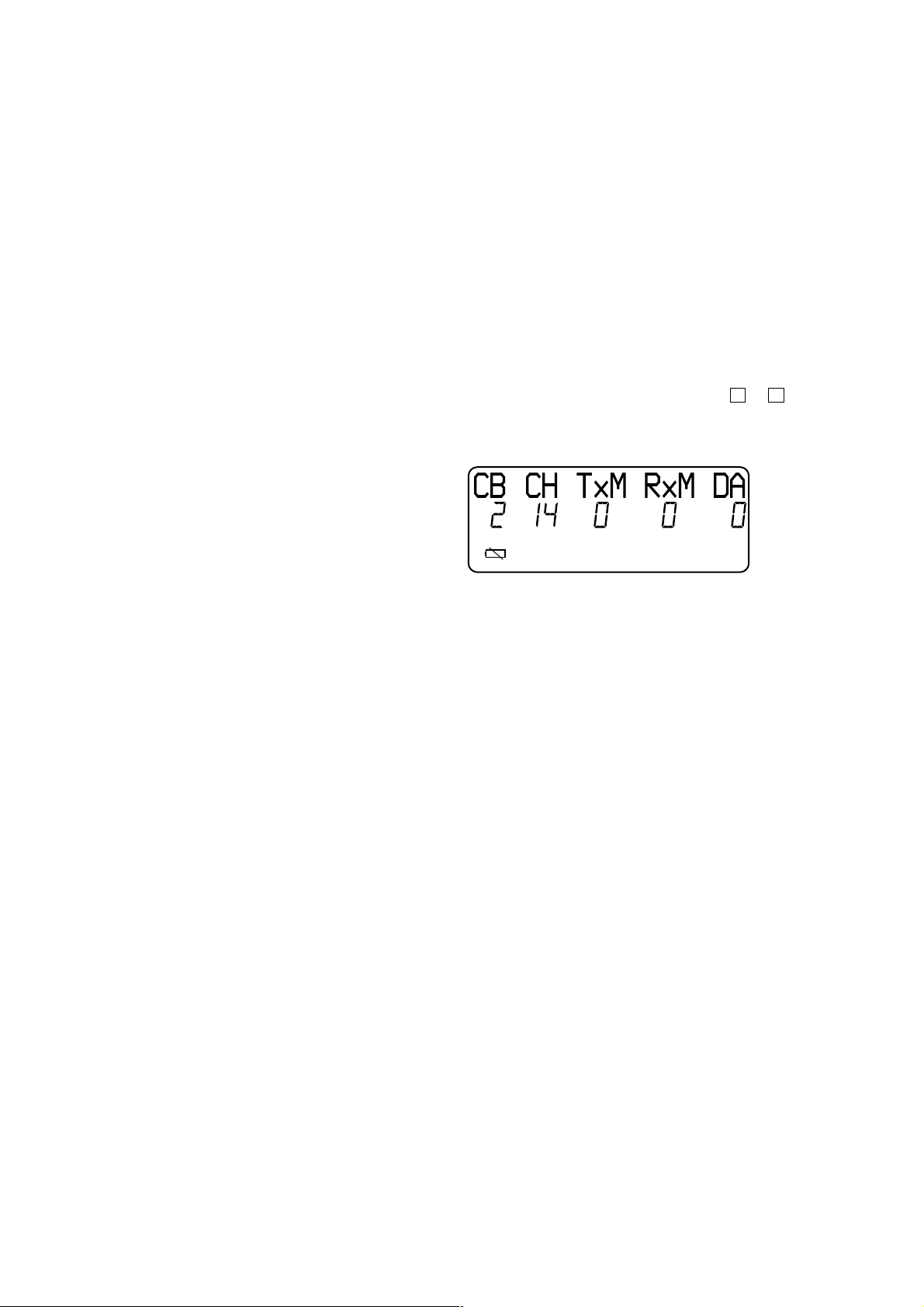
4. When enter the test mode, happ y tone is emitted, and the LCD
displays as shown below.
5. While pressing the [HANDSET LOCATOR] key of the base
unit A, turn the po wer on, then release and press it again within
2 seconds to enter the test mode.
6. When enter the test mode, the
7. Disconnect the po wer of the handset B, then connect the power
again.
8. Disconnect the power of the base unit A, then connect the po wer
again.
9. Cradle the handset B on the base unit A to charge the battery
of handset B for about 1 minute.
10. Press the [TALK] key of the handset B and join the base unit
A.
11. When joining is successful, the handset B is normal. But when
it fails, charge the battery of the handset B again.
12. Next, repeat the step 1 to step 9 with the handset A and base
unit B
13. When joining is successful with handset A and base unit B,
base unit B is normal and handset B is faulty.
[LINE] LED blinks slowly .
SAFETY-RELATED COMPONENT WARNING!!
COMPONENTS IDENTIFIED BY MARK 0 OR DOTTED
LINE WITH MARK 0 ON THE SCHEMATIC DIAGRAMS
AND IN THE PARTS LIST ARE CRITICAL TO SAFE
OPERATION. REPLACE THESE COMPONENTS WITH
SONY PARTS WHOSE PART NUMBERS APPEAR AS
SHOWN IN THIS MANU AL OR IN SUPPLEMENTS PUBLISHED BY SONY.
ATTENTION AU COMPOSANT AYANT RAPPORT
À LA SÉCURITÉ!
LES COMPOSANTS IDENTIFIÉS P AR UNE MARQUE 0
SUR LES DIAGRAMMES SCHÉMATIQUES ET LA LISTE
DES PIÈCES SONT CRITIQUES POUR LA SÉCURITÉ
DE FONCTIONNEMENT. NE REMPLACER CES COMPOSANTS QUE PAR DES PIÈCES SONY DONT LES
NUMÉROS SONT DONNÉS DANS CE MANUEL OU
DANS LES SUPPLÉMENTS PUBLIÉS PAR SONY.
2
SPP-N1020/N1021
Ver 1.1
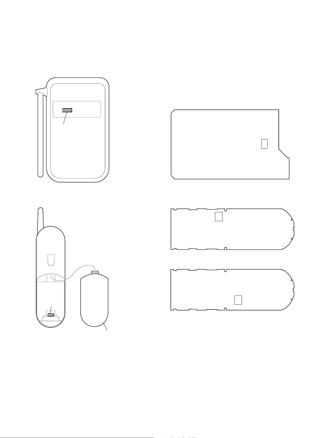
NEW/FORMER TYPE DISCRIMINATION
In this set with the following serial No. or later BASE MAIN and
HAND MAIN boards have been changed.
SPP-N1020 : Serial No. 0270853 or later
SPP-N1021 : Serial No. A0114793 or later
Serial No.
NOTE FOR REPAIRING AND REPLACEMENT OF THE
NEW TYPE BO ARD
When a new type board is damaged or out of order, do not repair
that board, but replace with an former type board (BASE MAIN
board : Part No. A-3062-659-A, HAND MAIN board : Part No.
A-3062-658-A (N1020)/A-3062-742-A(N1021)). In this case, remove the EEPROM (BASE MAIN board : Ref No. U6, HAND
MAIN board : Ref No. U4) from the new type board and install it
on the former type board as a replacement.
– BASE MAIN BOARD (Conductor Side) –
U6
Serial No.
Bottom View
Bottom View
– HAND MAIN BOARD (Component Side) –
U4
Former Type
U4
New Type
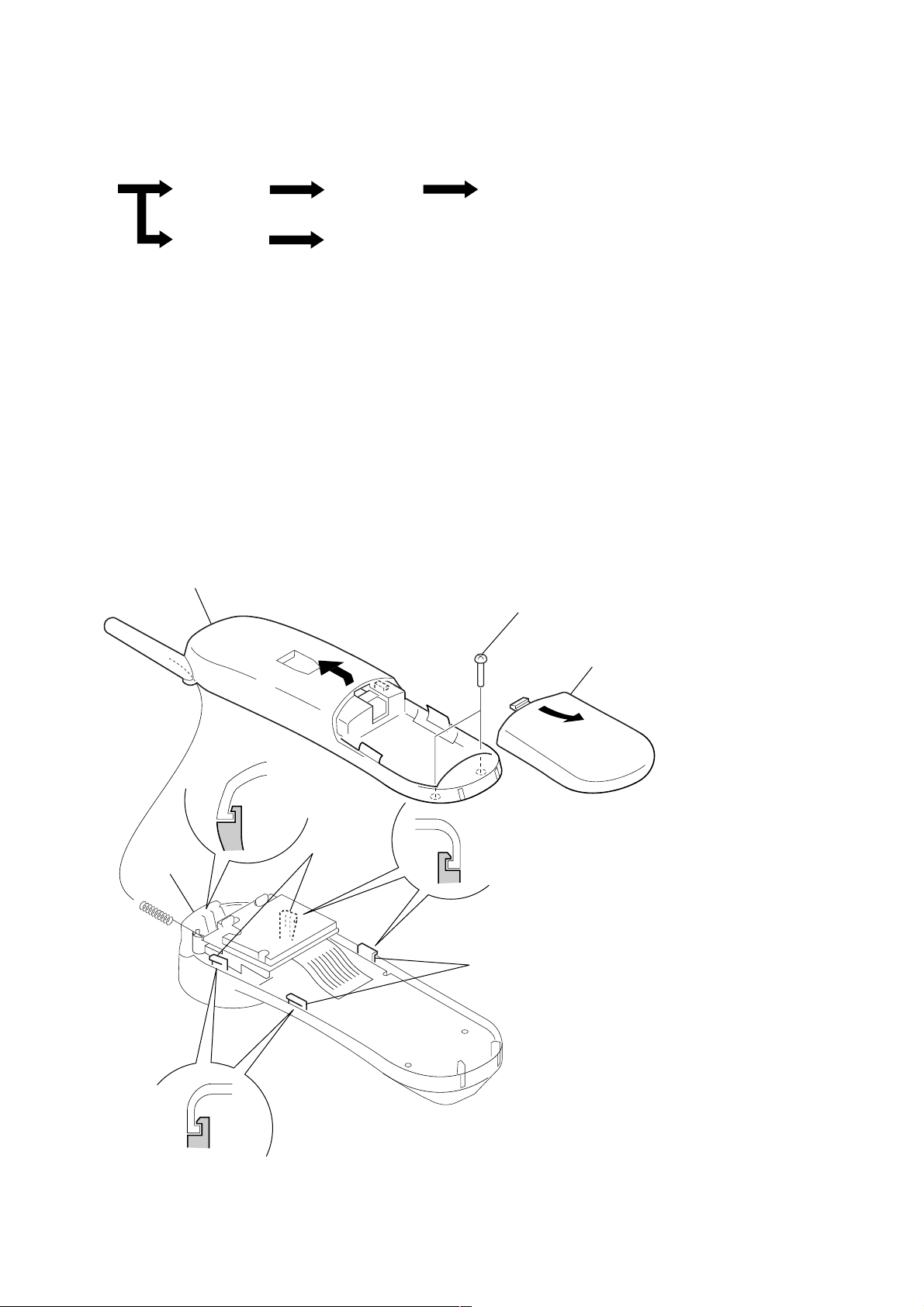
Lid Battery
3
SPP-N1020/N1021
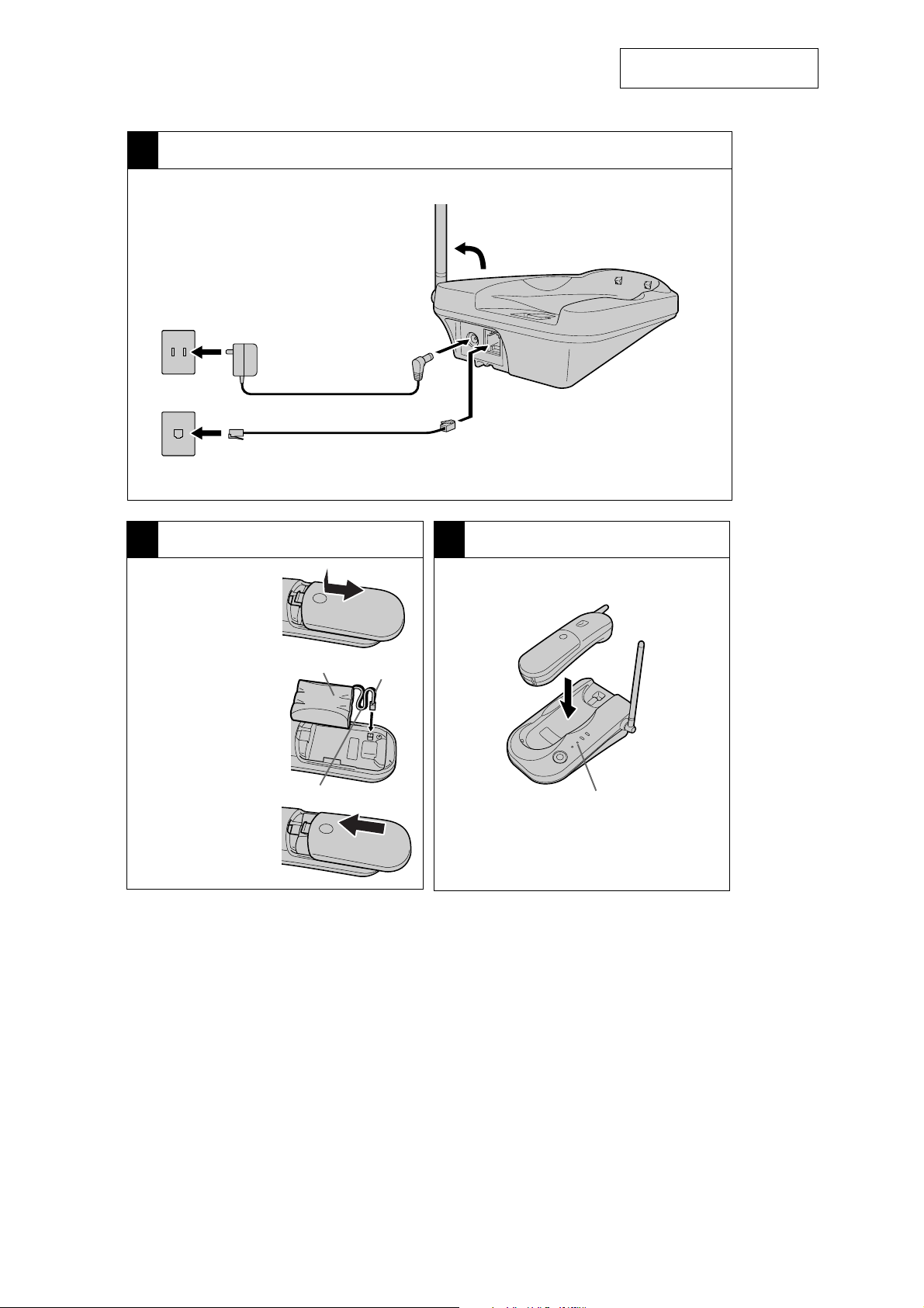
1 Set up the base unit
To AC outlet
To telephone outlet
SECTION 2
GENERAL
2 Connect the AC power
adaptor AC-T130.
1 Connect the telephone
line cord.
3 Raise the antenna.
To D C
IN 9V
To LINE
This section is extracted from
instruction manual.
2
Install the Battery Pack
1
Slide open the
battery
compartment
lid.
2
Connect the
battery
connector with
correct polarity
(black wire goes
on right side
and red wire
goes on left).
3
Insert the
battery pack,
and close the
lid.
BP-T18
Red
Black
3
Charge the Battery Pack
Place the handset on the base unit.
CHARGE lamp
Charge the battery pack for at least
12 hours.
4
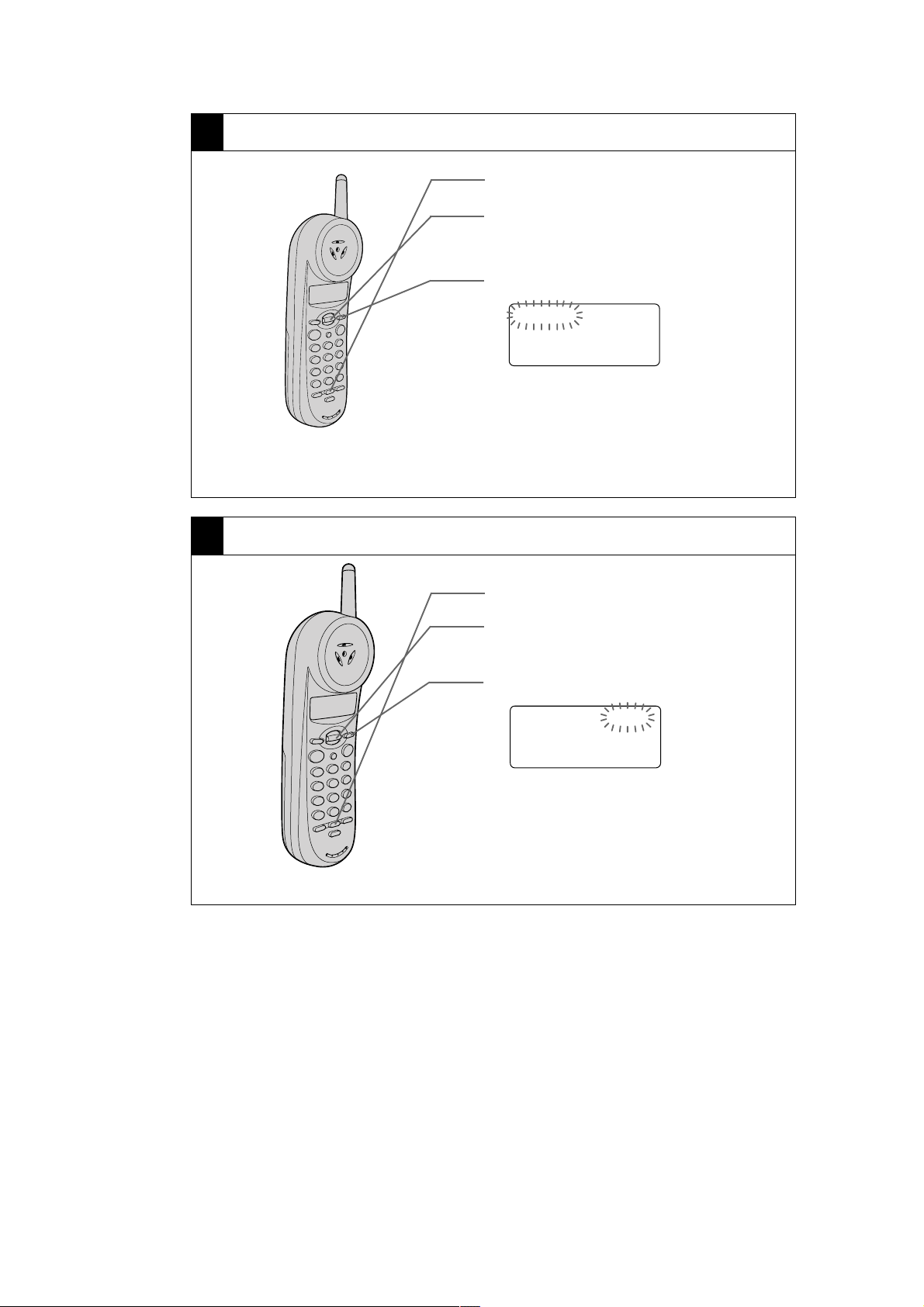
4 Change the display language
1
Press (PGM).
2
Raise or lower the Jog lever until
“LANGUAGE” or “IDIOMA” appears
on the display.
3
Press (SELECT).
ENGLISH ESPANOL
4
Raise or lower the Jog lever to
change the display language, and
then press (PGM).
SPP-N1020/N1021
5 Choose the dialing mode
1
Press (PGM).
2
Raise or lower the Jog lever until
“DIAL MODE” appears on the display.
3
Press (SELECT).
DIAL MODE: TONE
4
Raise or lower the Jog lever to choose
the dialing mode (“TONE” or
“PULSE”), and then press(PGM).
5
SPP-N1020/N1021
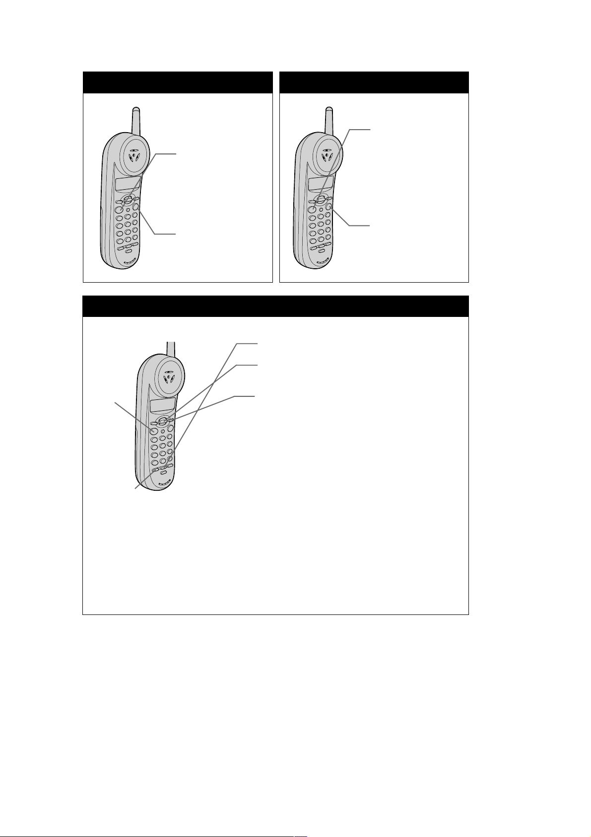
Making calls
1
Pick up the
handset.
2
Press (TALK) .
3
Dial the phone
number.
4
When you’re
done talking,
press (OFF).
One-touch dialing
Storing phone number
Receiving calls
1
When you hear
the phone ring,
pick up the
handset from
the base unit
and press
(TALK).
2
When you’re
done talking,
press (OFF).
1
Press (PGM).
2
Display “SET ONE TOUCH” using the
Jog lever.
3
(TALK)
(ONE TOUCH)
Press (SELECT).
4
Enter the phone number.
5
Press (PGM).
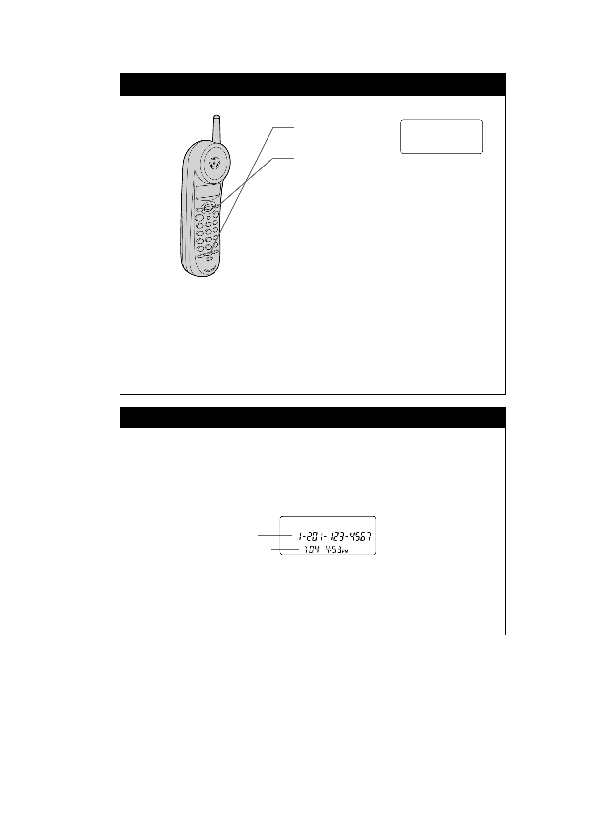
Making calls
1
Press (TALK) and wait until “TALK” appears on the display.
2
Press (ONE TOUCH).
Making Long Distance Calls
Please see "Making Long Distance Calls with one-touch dialing" of the
operating instructions for detail.
6
Phone Directory
Storing numbers and names
Making calls
SPP-N1020/N1021
1
Press (PGM).
2
Display "DIRECTORY" using the Jog
lever, then press (SELECT).
3
Enter the name using the dialing keys.
To enter two characters assigned to the
same key, raise the Jog lever to move
the cursor to the right.
4
Press (SELECT).
5
Enter the phone number.
6
Press (PGM).
DIRECTORY
1
Raise the Jog lever.
2
Display the name and phone number you want to call.
To search in alphabetical order: raise or lower the Jog lever.
To search by the initial character: press the dialing key of the desired
character, then lower the Jog lever.
3
Press (SELECT) twice.
Using Caller ID service
Caller ID requires subscription through local telephone company. Please
contact your local telephone company for details and availability of service.
When you receive a call
The phone number appears on the display with the date and time.
If your Caller ID service includes the caller name service, the caller’s name also
appears on the display.
Caller’s name
Caller’s phone number
The date and time received
In certain cases, the caller’s name or phone numbers will not be displayed.
Please see "When you receive a call" of the operating instructions for details.
You may need to change the number of digits of the phone number in the
Caller ID list by pressing (#) to call back or store into the Phone Directory.
Please see "To change the number of digits of the phone number" of the
operating instructions for detail.
SMITH JOHN
7
SPP-N1020/N1021
• This set can be disassembled in the order shown below.
3-1. DISASSEMBLY FLOW
SECTION 3
DISASSEMBLY
Set
Note: Follow the disassembly procedure in the numerical order given.
H/S rear assy H/S FRT assy
Base bottom
BASE MAIN board
3-2. H/S REAR ASSY
5
Remove the H/S rear assy
in the direction of arrow
B
.
HAND MAIN board
2
two screws
(BTP3
×
12)
4
claw
B
3
two claws
3
two claws
A
1
Remove the battery lid
in the direction of arrow
A
.
8
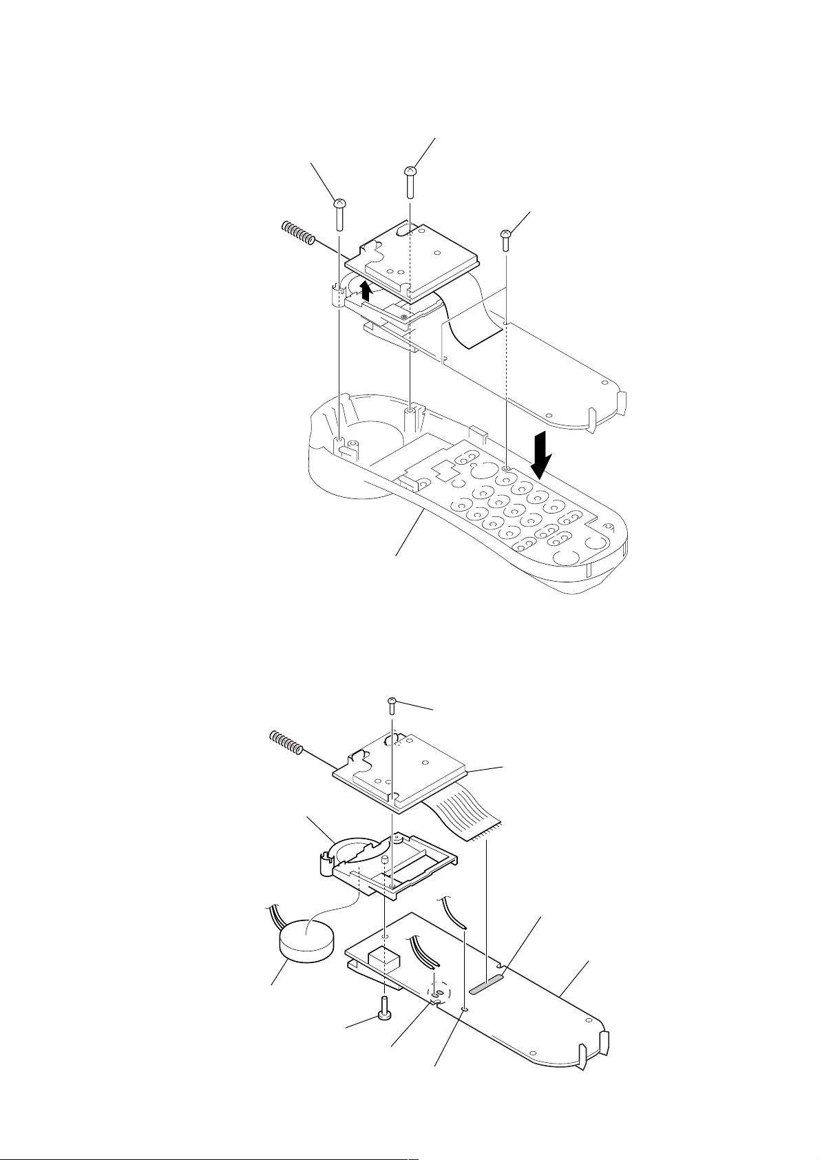
3-3. H/S FRT ASSY
d
3
screw
(BTP2.6
SPP-N1020/N1021
1
screw
(BTP2.6
×
8)
2
×
8)
4
two screws
(P2
×
5)
3-4. HAND MAIN BOARD
8
receiver BKT
6
H/S FRT assy
5
screw
(BTP2.6
×
8)
6
RF unit (hand)
5
2
speaker (2.8cm)
7
screw (BTP2.6 × 8)
1
Remove two solders of lead.
3
Remove solder of lead.
4
Remove twelve solders.
9
HAND MAIN boar
9
 Loading...