

Sony SPP-M100 Service Manual
SPP-M100
SERVICE MANUAL
SPECIFICATIONS
General
Frequency control
Crystal-controlled PLL
Operation mode
FM, duplex
Operation channel
25 channels
Dial signal
Tone, 10 PPS (pulse) selectable
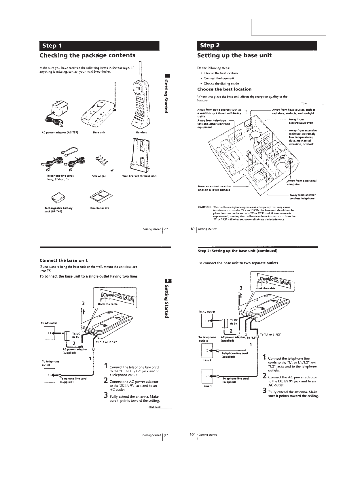
Supplied accessories
AC power adaptor (AC-T37), Telephone line
cords (long :2 / short : 1), Screws (4), Wall bracket
for base unit, Rechargeable battery pack
(BP-T40), Directories (2)
E Model
Base unit
power source
DC 9V from AC power adaptor
Battery charging time
Apprpx. 10 hours
Dimensions
Approx. 53/4 x 13/4 x 91/4 inches
(w/h/d), antenna excluded
(Approx. 146 x 44 x 234 mm)
Antenna : 227/8 inches (580 mm)
Mass
Approx. 13.5 oz (Approx. 390g, ) battery
inclueded
MICROFILM
Handset
power source
Rechargeable battery pack BP-T40
Battery life
Standby : Approx. 30 days
Dimensions
Approx. 23/8 x 81/8 x 23/4 inches
(w/h/d), antenna excluded
(Approx. 58 x 205 x 69 mm)
Antenna : 31/4 inches (81 mm)
Mass
Approx. 10.5 oz (Approx. 300g, ) battery
inclueded
Design and specifications are subject to change without notice.
2-LINE CORDLESS TELEPHONE

TABLE OF CONTENTS
Specifications ........................................................................... 1
1. GENERAL
Location and Function of Controls .................................... 3
Step 1 : Checking the Package Contents............................ 5
Step 2 : Setting up the Base Unit ....................................... 5
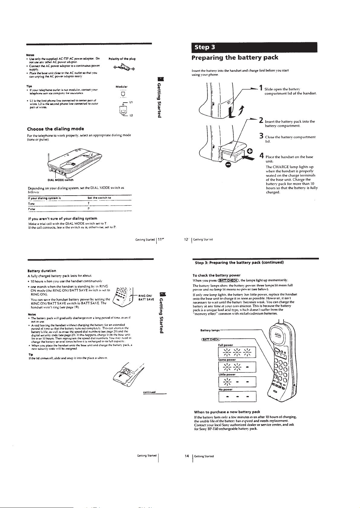
Step 3 : Preparing the Battery Pack ................................... 6
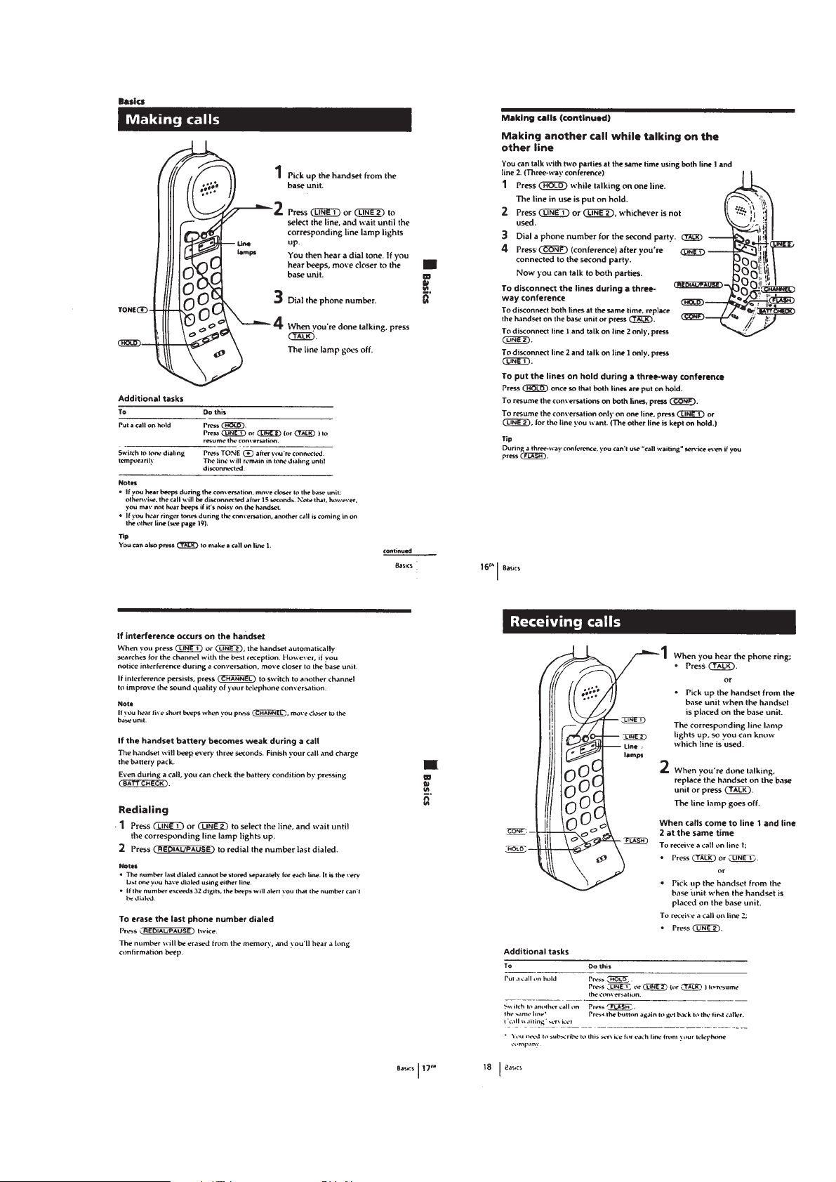
Making Calls ...................................................................... 7
Receiving Calls .................................................................. 7
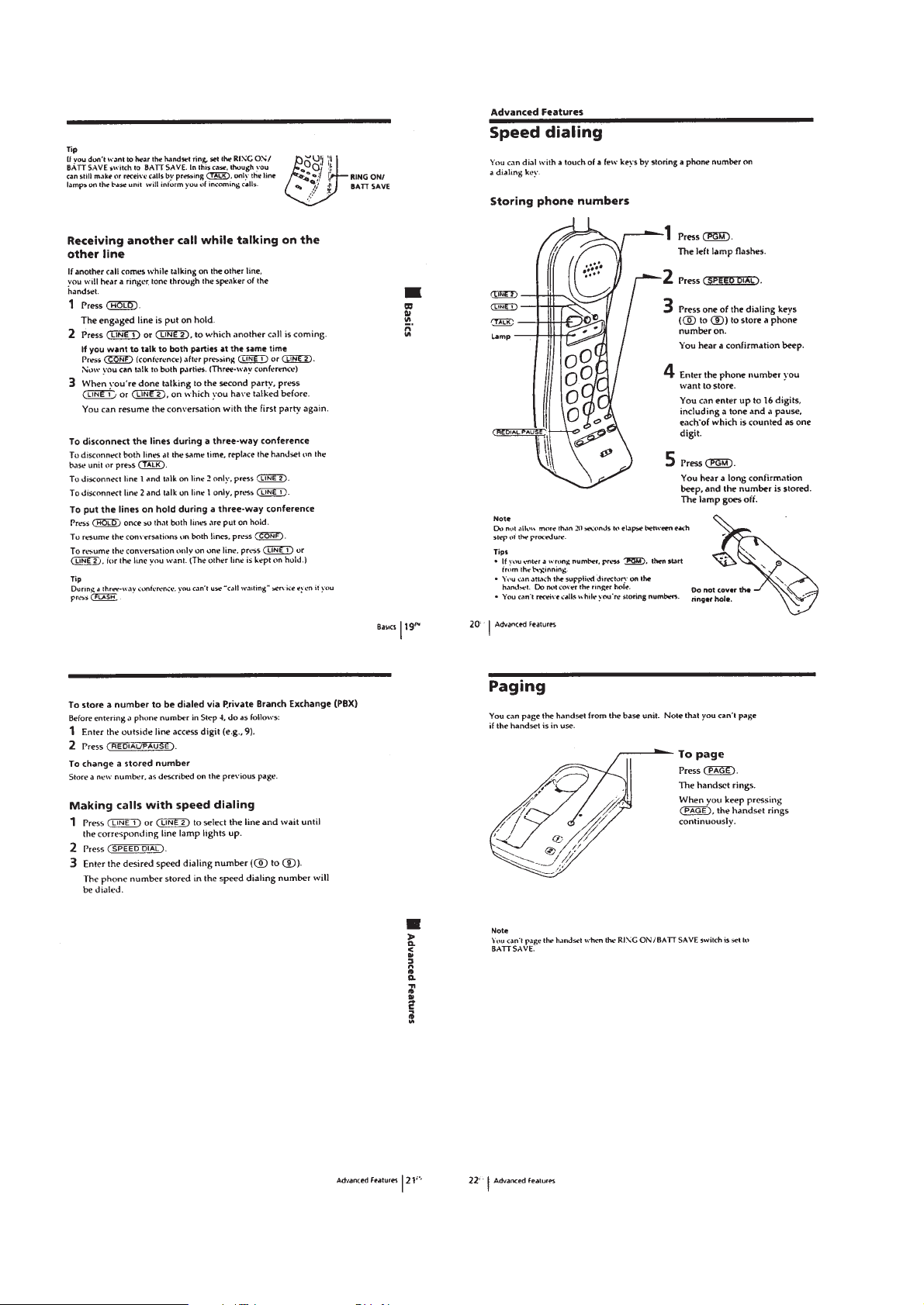
Speed Dialing..................................................................... 8
Paging ................................................................................ 8
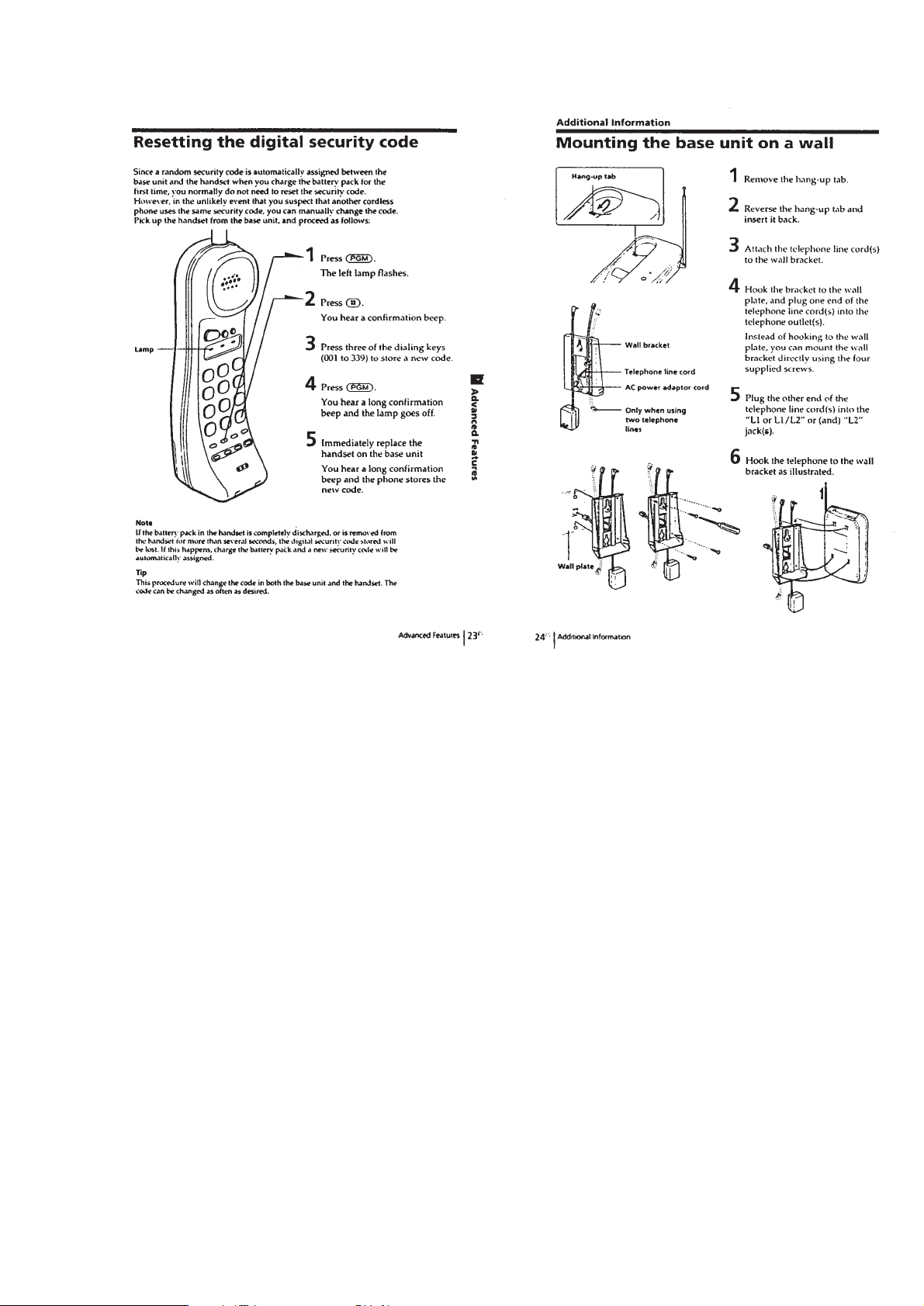
Reseting the dDigital Security Code.................................. 9
Mounting the Base Unit on a Wall ..................................... 9
2. DISASSEMBLY
2-1. Cover (Battery) Removal.......................................... 10
2-2. Rear (Cabinet) Removal ........................................... 10
2-3. Hand Main Board Removal ...................................... 10
3. TEST MODE .......................................................... 11
4 . BASE UNIT TEST MODE
STATUS FLOW CHART ......................................18
5. ELECTRICAL ADJUSTMENTS
5-1. Base Unit Section ..................................................... 19
5-2. Handset section......................................................... 20
6. DIAGRAMS
6-1. Explanation of IC Terminals..................................... 22
6-2. Block Diagram (Base Unit Section) ......................... 24
6-3. Block Diagram (Handset Section) ............................ 27
6-4. Printed Wiring Boards (Base Unit Section).............. 30
6-5. Schematic Diagram (Base Unit Section) .................. 33
6-6. Schematic Diagram (Handset Section) ..................... 37
6-7. Printed Wiring Boards (Handset Section) ................ 41
7. EXPLODED VIEWS
7-1. Base Unit Section ..................................................... 47
7-2. Handset Section ........................................................ 48
8. ELECTRICAL PARTS LIST ................................49
Notes on chip component replacement
• Never reuse a disconnected chip component.
• Notice that the minus side of a tantalum capacitor may be damaged by heat.
SAFETY-RELATED COMPONENT WARNING!!
COMPONENTS IDENTIFIED BY MARK ! OR DOTTED LINE WITH
MARK !ON THE SCHEMATIC DIAGRAMS AND IN THE PARTS
LIST ARE CRITICAL TO SAFE OPERATION.
REPLACE THESE COMPONENTS WITH SONY PARTS WHOSE
PART NUMBERS APPEAR AS SHOWN IN THIS MANUAL OR IN
SUPPLEMENTS PUBLISHED BY SONY.
– 2 –
LOCATION AND FUNCTION OF CONTROLS
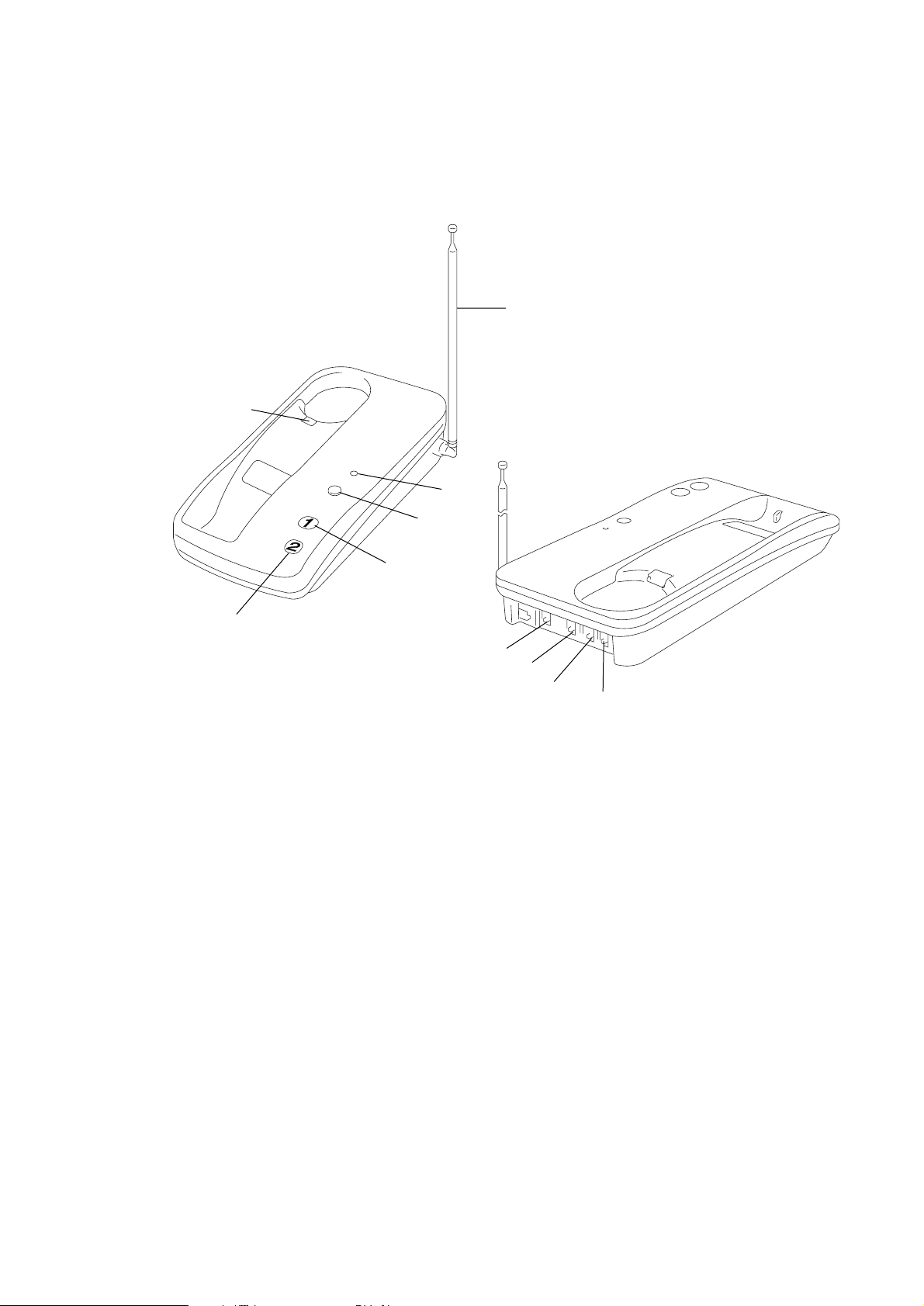
BASE UNIT
1
SECTION 1
GENERAL
6
5
2
4
3
7
8
9
1 Hang-up tab
2 LINE 2 lamp
3 LINE 1 lamp
4 PAGE button
5 CHARGE lamp
6 Telescopic antenna
7 DIAL MODE switch
8 DC IN 9V jack
9 L2 (Telephone jack)
!º L1 or L1/L2 (Telephone jack)
!º
– 3 –
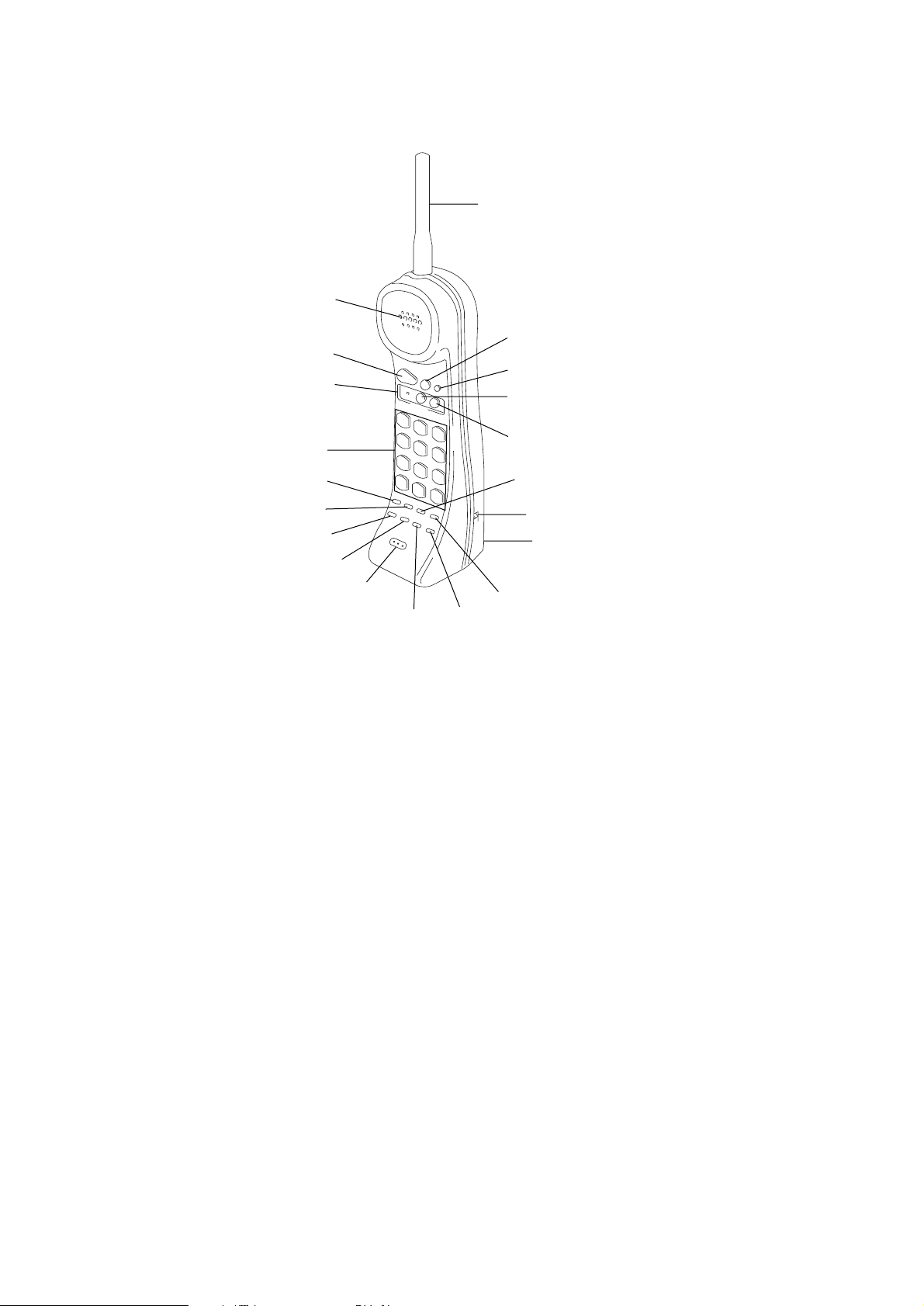
HANDSET
@º
1
2
3
4
5
6
7
8
9
!º
1 SPEAKER
2 TALK button
3 Battery lamps (lndicate battery level)
4 Dialing keys
5 REDIAL/PAUSE button
6 PGM button
7 HOLD button
8 CONF button
9 Microphone
!º FLASH button
!ª
!•
!¶
!§
!∞
!¢
!™
!£
!¡
!¡ BATT CHECK button
!™ Battery conmpartment
!£ SPEED DIAL button
!¢ RING ON/BATT SAVE switch
!∞ CHANNEL button
!§ LINE 2 lamp
!¶ LINE 1 lamp
!• LINE 2 button
!ª LINE 1 button
@º Helical antenna
– 4 –
This section is extracted from
instruction manual.
– 5 –
– 6 –
– 7 –
– 8 –
– 9 –
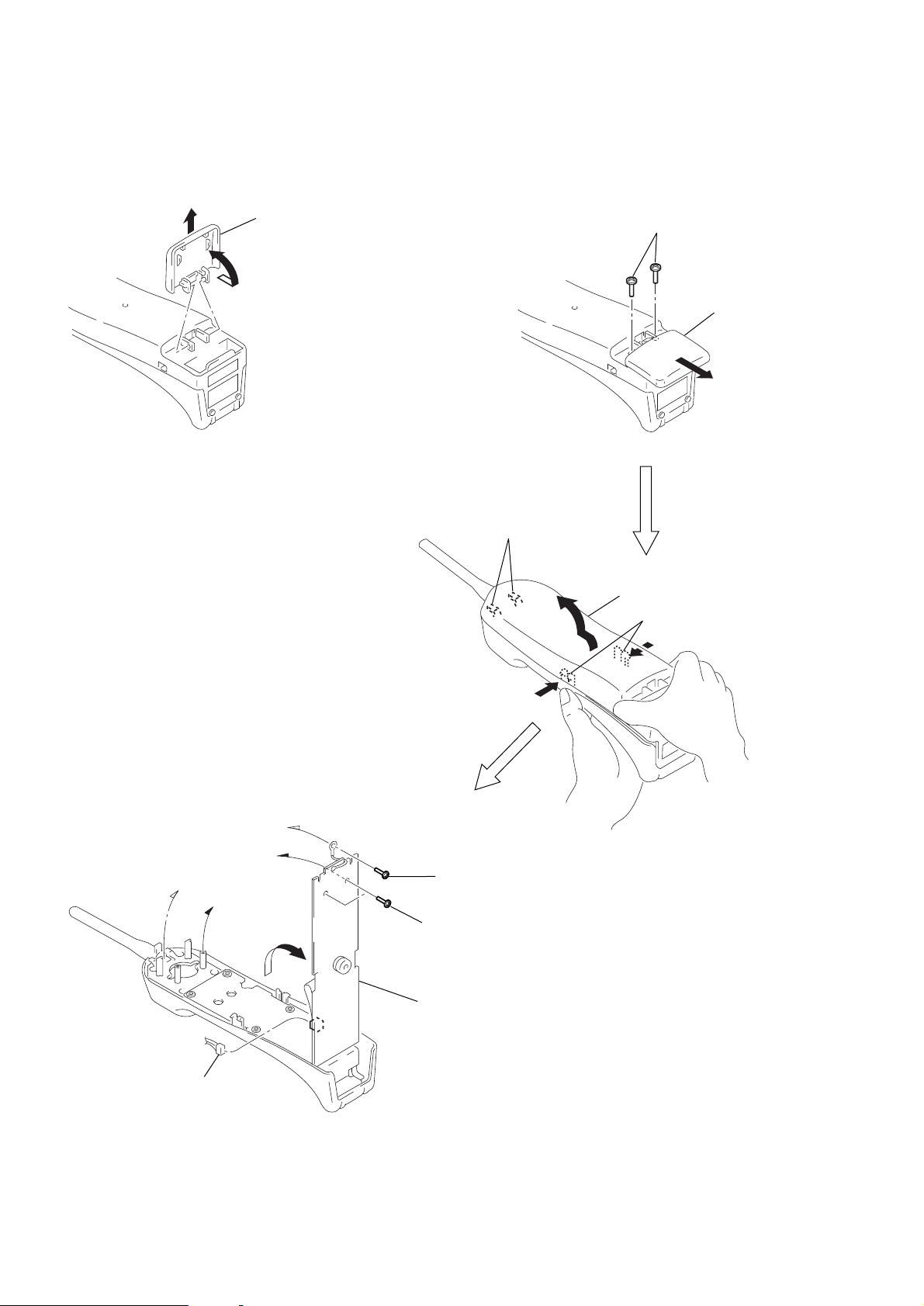
DISASSEMBLY
Note : Follow the disassembly procedure in the numerical order given.
r
HANDSET
2-1. COVER (BATTERY)
SECTION 2
2-2. REAR CABINET
2
Cover (battery)
1
Two claws
2
Two screws
(BTP 2.6X12)
3
Rear cabinet
Two claws
1
Cover (bettery)
2-3. HAND MAIN BOARD
3
Connector
(CN502)
1
Screw
(BTP 2.6X8)
2
Two screws
(BTP 2.6X8)
4
Hand main board
– 10 –
BASE UNIT
)
1. How to enter the test mode
1-1. Manual test mode
Set the [DIALMODE] switch to “P” (Pulse).
While pressing the
[PAGE] key, switch on the power
supply. (Reset start)
With the
[PAGE] key still held down, switch the
[DIALMODE] switch “P” (Pulse)n“T” (Tone)n“P”
(Pulse). When you release the
starts.
If you release the
[PAGE] key during this process, the
machine operates in normal mode.
<How to Release the Test Mode>
• Pull out the AC adapter and turn off the power.
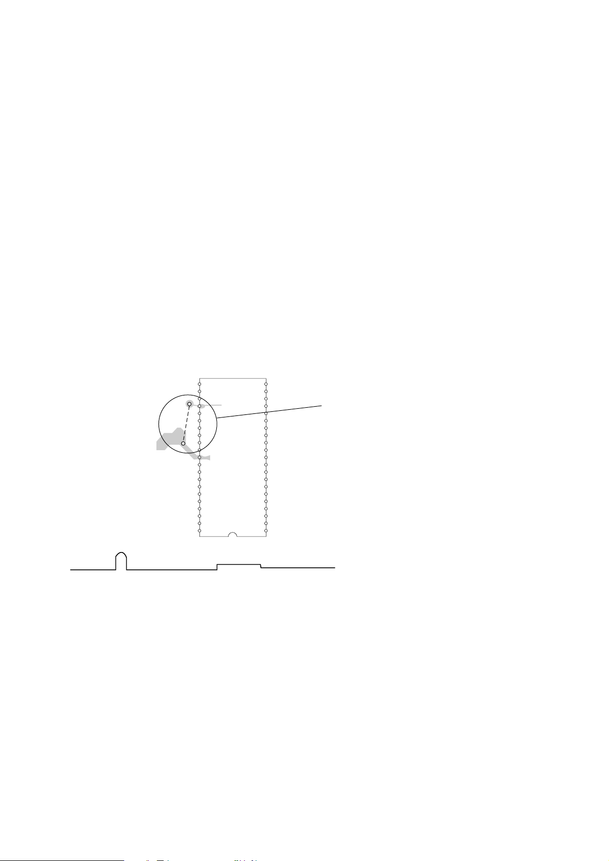
1-2. Machine test mode
Set the [DIALMODE] switch to “P” (Pulse).
If you switch on the power with the TEST I/O port (IC501
!• pin) set to high (connect TP7 to TP608), the machine
enters test mode.
[PAGE] key, test mode
SECTION 3
TEST MODE
[BASE MAIN BO ARD] (Component Side)
22
25
30
35
40
42
TP7
TP608
21
20
15
IC501
10
5
1
<How to Release the Test Mode>
1) Pull out the AC adapter and turn off the power.
2) Remove the short plug and turn on the power again.
TEST MODE terminal
Open : Normal
(
Short : Test mode
– 11 –
 Loading...