

Page 1
SPP-IM977
pp
SERVICE MANUAL
Ver 1.0 2000. 07
SPECIFICATIONS
General
Frequency band
902 - 928 MHz
Operating channel
30 channels
Dial signal
Tone, 10 PPS (pulse) selectable
Supplied accessories
AC power adaptor (AC-T128)
Telephone line cords (3)
Wall bracket for base phone
Rechargeable battery pack (BP-T23)
Belt clip
Base phone
Power source
DC 9V from AC power adaptor
AC-T128
Battery charging time
Approx. 24 hours
Dimensions
Approx. 185 x 70 x 225 mm (w/h/d),
antenna excluded
(approx. 7
Antenna: Approx. 150 mm
(approx. 6 inches)
Mass
Approx. 662 g
(approx. 1 lb 7 oz), wall bracket excluded
3
⁄ 8 x 2 7⁄8 x 8 7⁄8 inches)
US Model
Handset
Power source
Rechargeable battery pack BP-T23
Battery charging time
Approx. 12 hours
Battery life
Standby: Approx. 7 days
Talk: Approx. 7 hours
Dimensions
Approx. 57 x 190 x 48 mm (w/h/d),
antenna excluded
(approx. 2
Antenna: Approx. 87 mm
(approx.
Mass
Approx. 268 g
(a
1
⁄4 x 7 1⁄2 x 1 15⁄16 inches)
1
3
⁄2 inches)
rox. 9.5 oz), battery included
Design and specifications are subject to
change without notice.
2-LINE CORDLESS TELEPHONE
Page 2

TABLE OF CONTENTS
1. GENERAL
Identifying the Parts ........................................................ 3
Setting Up the Base Phone ............................................. 4
Preparing the Battery Pack ............................................. 5
Entering the Area code.................................................... 5
Making Calls ................................................................... 6
Receiving Calls ............................................................... 8
Telephone Features ......................................................... 9
Caller ID Features ........................................................... 13
2. DISASSEMBLY ......................................................... 17
3. ELECTRICAL ADJUSTMENTS
Base Unit ......................................................................... 20
Handset ............................................................................ 21
4. DIAGRAMS
4-1. Block Diagram – MAIN Section – ................................ 23
4-2. Block Diagram – DISPLAY/
KEY SHIFT/POWER SUPPLY Section – ..................... 25
4-3. Block Diagram – HANDSET Section – ........................ 27
4-4. Note for Printed Wiring Boards and
Schematic Diagrams ....................................................... 29
4-5. Printed Wiring Board
– BASE MAIN Board (Component Side) – ................... 31
4-6. Printed Wiring Board
– BASE MAIN Board (Conductor Side) –..................... 33
4-7. Schematic Diagram – BASE MAIN Board (1/3) –....... 35
4-8. Schematic Diagram – BASE MAIN Board (2/3) –....... 37
4-9. Schematic Diagram – BASE MAIN Board (3/3) –....... 39
4-10. Printed Wiring Board – BASE KEY Board – ............... 41
4-11. Schematic Diagram – BASE KEY Board – .................. 42
4-12. Printed Wiring Board – HAND MAIN Board – .......... 43
4-13. Schematic Diagram – HAND MAIN Board – .............. 45
NOTE FOR REPLACEMENT OF THE EEPROM
The ID cord is written in the EEPROM.
When replacing the EEPROM, U1011 on the B ASE MAIN board
and U1006 on HAND MAIN board should be replaced together as
a pair.
5. EXPLODED VIEWS ................................................ 50
6. ELECTRICAL PARTS LIST ............................... 52
Notes on chip component replacement
• Never reuse a disconnected chip component.
• Notice that the minus side of a tantalum capacitor may be dam-
aged by heat.
Flexible Circuit Board Repairing
• Keep the temperature of the soldering iron around 270 ˚C dur-
ing repairing.
• Do not touch the soldering iron on the same conductor of the
circuit board (within 3 times).
• Be careful not to apply force on the conductor when soldering
or unsoldering.
SAFETY-RELATED COMPONENT WARNING!!
COMPONENTS IDENTIFIED BY MARK 0 OR DOTTED
LINE WITH MARK 0 ON THE SCHEMA TIC DIAGRAMS
AND IN THE PARTS LIST ARE CRITICAL TO SAFE
OPERATION. REPLACE THESE COMPONENTS WITH
SONY PARTS WHOSE PART NUMBERS APPEAR AS
SHOWN IN THIS MANUAL OR IN SUPPLEMENTS PUBLISHED BY SONY.
– 2 –
Page 3
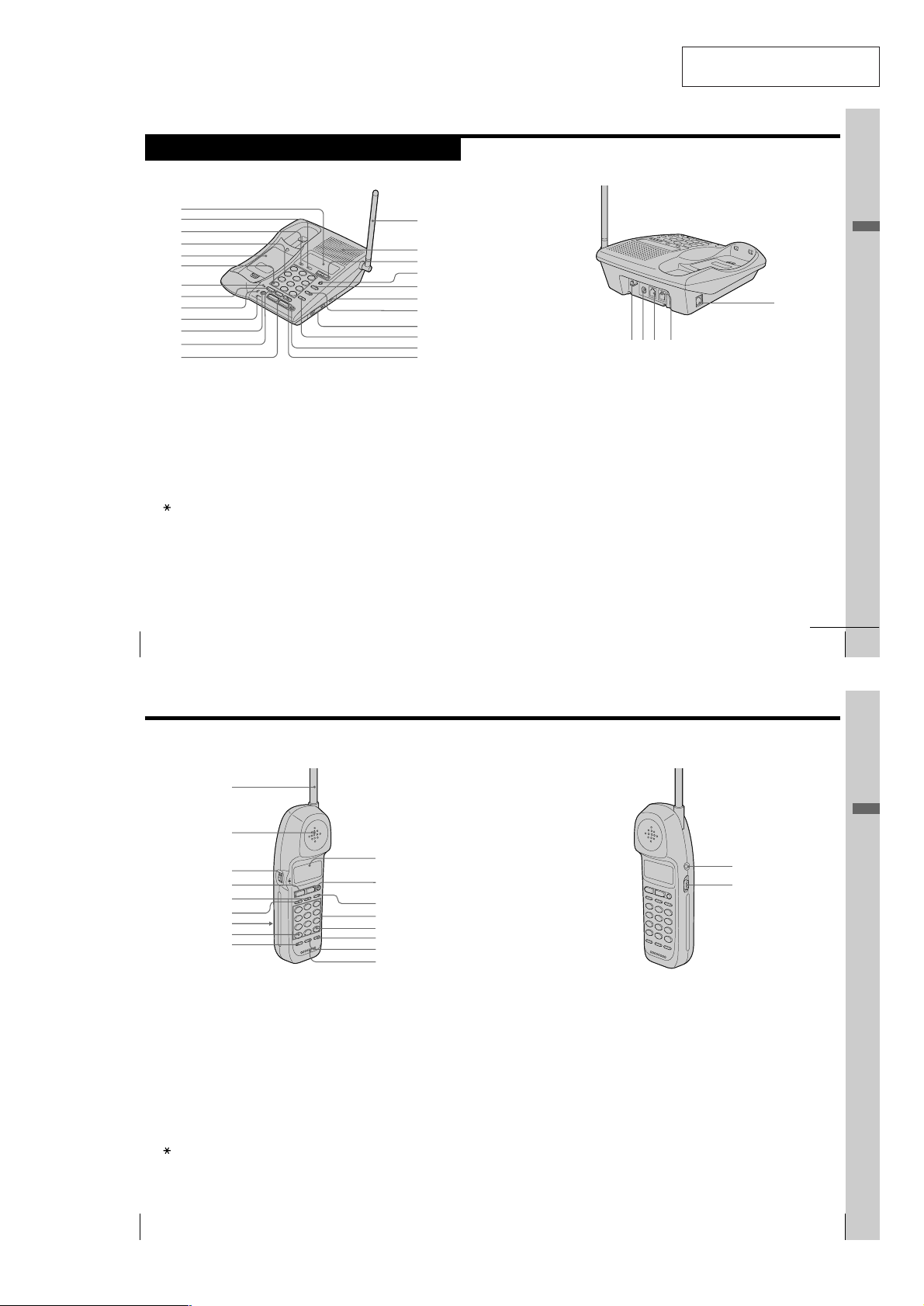
Identifying the parts
Refer to the pages indicated in parentheses for details.
Base Phone
1
2
3
4
5
6
7
8
9
0
qa
qs
qd
SECTION 1
GENERAL
qf
qg
qh
qj
qk
ql
w;
wa
ws
wd
wf
This section is extracted from
instruction manual.
Getting Started
wl
wh wkwgwj
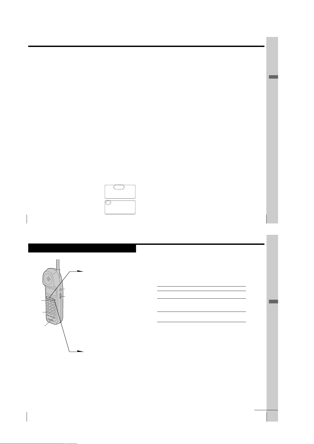
1 Display window (p. 24, 34, 52)
2 MESSAGES lamp (p. 61)
Flashes when you have messages.
3 NEW CALL lamp (p. 53)
Flashes when there is a “NEW”
data in the Caller ID list.
4 Dialing keys (p. 27)
5 Battery compartment (p. 16)
6
TONE button (p. 25)
Allows you to switch temporarily to
tone dialing.
7 SPARE BATTERY lamp (p. 16)
Lights while the spare battery is
being charged.
8 HOLD button (p. 32)
Puts a call on hold.
US
Getting Started
20
Identifying the parts (continued)
Handset
1
2
3
4
5
6
7
8
9
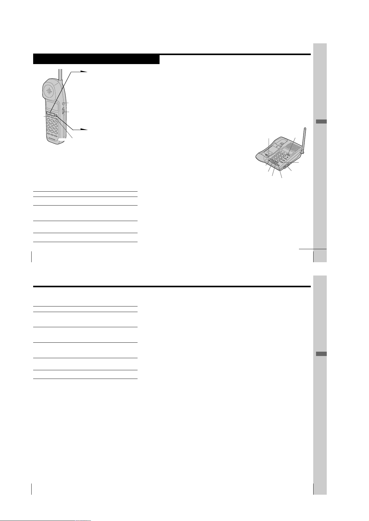
9 CHARGE lamp (p. 14)
Lights while the battery is being
charged.
0 MIC (microphone)
qa MUTING button (p. 27)
Mutes your voice during a
conversation.
qs CONF (conference) button
(p. 49)
Lets you talk with two parties at the
same time.
qd LINE buttons (1, 2) (p. 27, 31)
Lets you make or receive a call.
qf Antenna (p. 11, 63)
qg Speaker
qh VOLUME +/– buttons
(p. 27, 32)
Adjusts the speaker volume or
press to move the cursor on the
display.
0
qa
qs
qd
qf
qg
qh
qj
qj PGM (program) button (p. 34)
Used to store numbers for speed
dialing.
qk REDIAL/PAUSE button
(p. 28, 35)
Redials the last number called/
inserts a pause in the dialing
sequence.
ql DIAL MODE switch (p. 13)
Selects pulse or tone dialing.
w; SPEED DIAL button (p. 34)
Automatically dials the numbers
programmed.
wa RINGER LEVEL switches
(L1, L2) (p. 32)
Adjusts the ringer volume.
ws FLASH button (p. 32, 60)
Switches to a second call if you
have “call waiting” service, or lets
you make a new call.
wd OFF button (p. 27)
Allows you to disconnect the call.
wf INTERCOM button (p. 45)
Lets you talk by using the base
phone and handset.
wg Hook for AC power adaptor
cord (p. 11)
wh DC IN 9V jack (p. 11, 63)
wj L1/L1+L2 jack (p. 11, 63)
wk L2 jack (p. 12, 63)
wl DATA jack (p. 13)
continued
Getting Started
qkqlqkqk
US
21
Getting Started
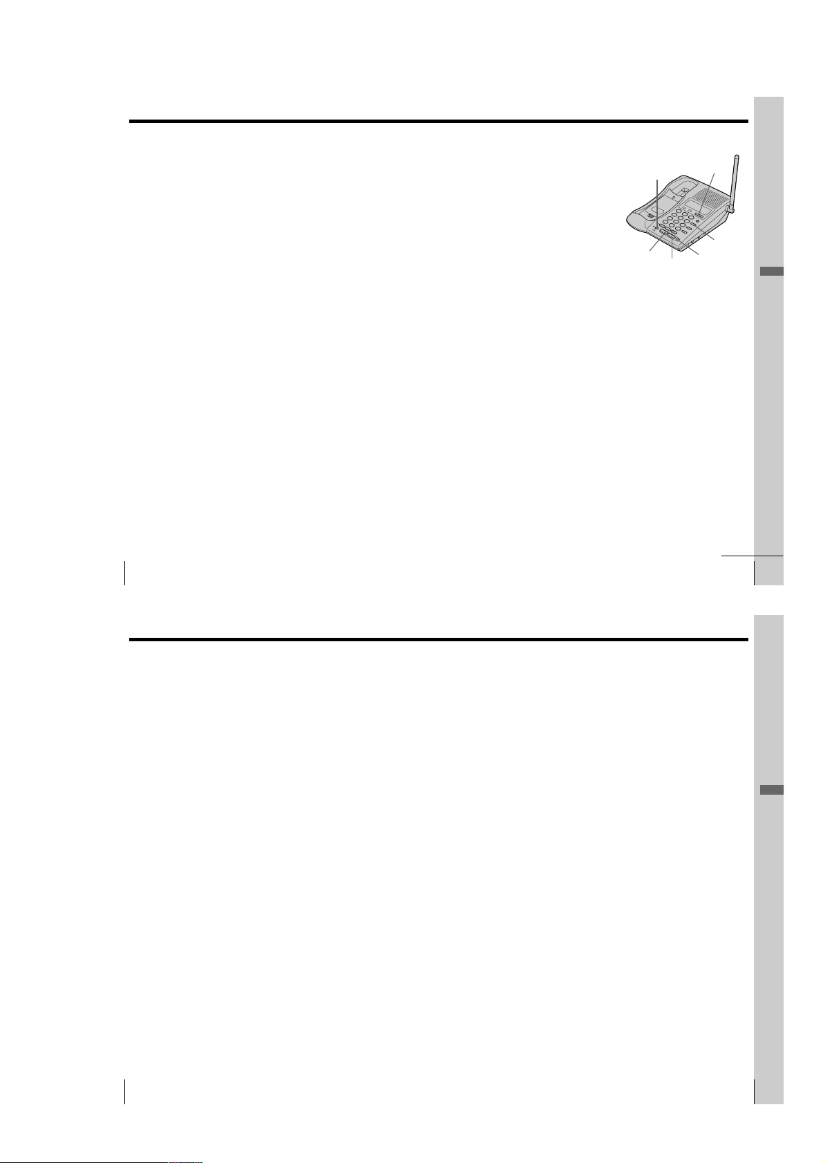
1 Antenna
2 Speaker
3 Jog Dial (p. 17, 37, 53)
4 LINE buttons (1, 2) (p. 24, 30)
Lets you make or receive a call.
5 INTERCOM button (p. 45)
Lets you talk by using the base
phone and handset.
6 HOLD button (p. 25)
Puts a call on hold.
7 Battery compartment (p. 14)
TONE button (p. 25)
8
Allows you to switch temporarily to
tone dialing.
US
Getting Started
22
9 CONF (conference) button
(p. 49)
Lets you talk with two parties at the
same time.
q; Display window (p. 24, 52)
qa OFF button (p. 24)
Allows you to disconnect the call.
qs FLASH/CALL WAITING button
(p. 30, 60)
Switches to a second call if you
have “call waiting” service, or lets
you make a new call.
qd Dialing keys (p. 24)
qf # button (p. 58)
Used to change the number of
digits of the phone number in the
Caller ID list.
– 3 –
qg REDIAL/PAUSE button
(p. 28, 38)
Redials the last number called/
inserts a pause in the dialing
sequence.
qh PGM (program) button
(p. 17, 37)
Used to store numbers in Phone
Directory.
qj Microphone
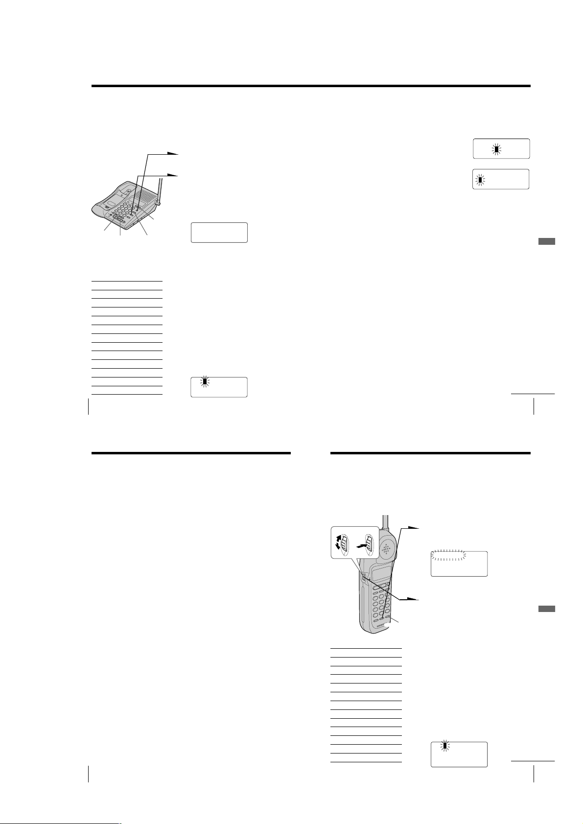
qk I (HEADSET) jack (p. 25, 30, 64)
ql VOL (volume) switch (p. 25)
Adjusts the handset volume.
Getting Started
US
23
Page 4
Step 2
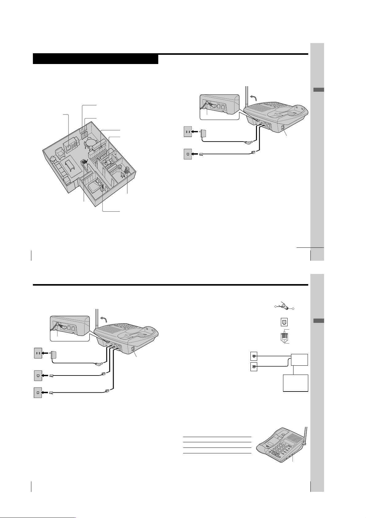
Setting up the base phone
Do the following steps:
• Choose the best location
• Connect the base phone
• Choose the dialing mode
Choose the best location
Where you place the base phone affects the reception quality of the
handset.
Away from television
sets and other
electronic equipment
Near a central location
and on a level surface
CAUTION: • Should you experience intermittent loss of audio during a conversation, try
moving closer to the base or move base phone away from other noise sources.
• The cordless telephone operates at a frequency that may cause interference to
nearby TVs and VCRs; the base phone should not be placed near or on the top
of a TV or VCR; and, if interference is experienced, moving the cordless
telephone farther away from the TV or VCR will often reduce or eliminate the
US
10
interference.
Getting Started
Away from noise sources such as a window
by a street with heavy traffic
Away from heat sources, such as radiators,
airducts, and sunlight
Away from a microwave
oven
Away from excessive
moisture, extremely low
temperatures, dust,
mechanical vibration, or
shock
Away from a personal
computer
Away from another
cordless telephone
Connect the base phone
If you want to hang the base phone on the wall, see page 63.
To connect the base phone to a single outlet having two lines
3
Hook the cord.
To an AC outlet
To the
telephone outlet
AC power adaptor
2
(supplied AC-T128)
Telephone line cord
1
(supplied)
To DC IN 9V
To L1/L1+L2
1 Connect the telephone line cord
to the L1/L1+L2 jack and to a
telephone outlet.
2 Connect the AC power adaptor
to the DC IN 9V jack and to an
AC outlet.
3 Raise the antenna. Make sure it
points towards the ceiling.
DATA jack
continued
Getting Started
Getting Started
US
11
Step 2: Setting up the base phone (continued)
To connect the base phone to two separate outlets
Hook the cord.
US
12
Getting Started
To an AC outlet
To the
telephone outlets
Line 1
1
Line 2
AC power adaptor
2
(supplied AC-T128)
Telephone line cord (supplied)
Telephone line cord (supplied)
To DC IN 9V
To L1/L1+L2
3
DATA jack
To L2
1 Connect the telephone line
cords to the L1/L1+L2 and L2
jacks and to the telephone
outlets.
2 Connect the AC power adaptor
to the DC IN 9V jack and to an
AC outlet.
3 Raise the antenna. Make sure it
points towards the ceiling.
Notes
• Use only the supplied AC-T128 AC power adaptor.
Do not use any other AC power adaptor.
• Connect the AC power adaptor to a continuous power
supply.
• Place the base phone close to the AC outlet so that
you can unplug the AC power adaptor easily.
Tips
• If your telephone outlet is not modular, contact your
telephone service company for assistance.
• L1 is the first phone line connected to center pair of
wires. L2 is the second phone line connected to outer
pair of wires.
Connecting a computer or FAX
You can connect a computer or FAX, etc. to the
DATA jack.
Notes
• L2 jack is used for receiving or sending
computer or FAX data in addition to making
or receiving calls.
If a call comes in on L2 jack with the “call waiting” service while a
computer or FAX connected to the DATA jack is receiving or sending
data, that data may be effected.
If you have data communication frequently, we recommend that you
and your callers use L2 jack for data communication only.
• If you have only single outlet having one line, connect the telephone
line cord to the L2 jack.
Polarity of the plug
–
Modular
To L1/L1+L2
and/or L2
Choose the dialing mode
For the telephone to work properly, select an appropriate dialing mode
(tone or pulse).
Depending on your dialing system, set the DIAL
MODE switch as follows:
If your dialing system is Set the switch to
Tone TONE
Pulse PULSE
If you aren't sure of your dialing system
Make a trial call with the DIAL MODE switch set
to TONE.
If the call connects, leave the switch as is;
otherwise, set to PULSE.
+
L1
L2
SPP-IM977
To DATA
Computer
or
FAX
DIAL MODE
switch
Getting Started
Getting Started
US
13
– 4 –
Page 5
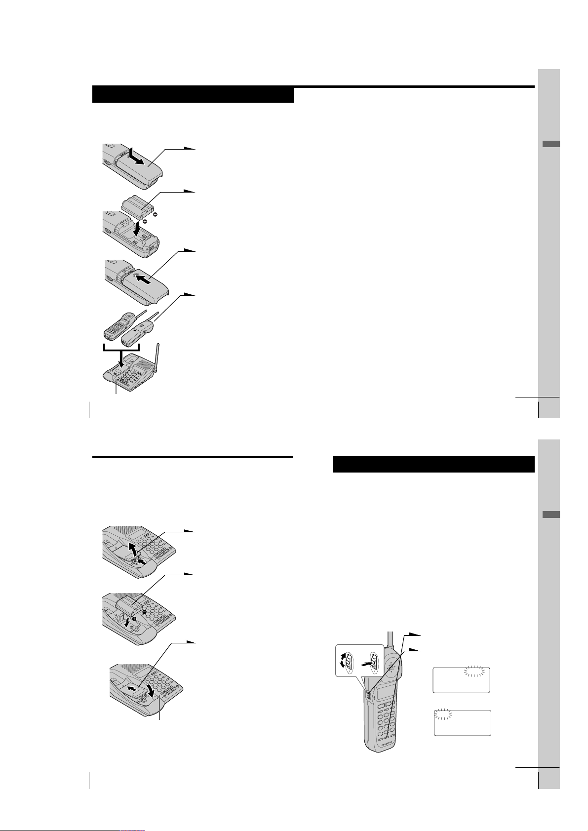
Step 3
Preparing the battery pack
Charge the battery pack for more than 12 hours before you start using
your phone.
1 Slide open the battery
compartment lid of the handset.
2 Insert the battery pack (with
contacts facing down) into the
battery compartment.
3 Close the battery compartment
lid.
4 Place the handset on the base
phone.
You can place it with either side
facing up.
The CHARGE lamp lights up
when the handset is properly
seated on the charge terminals
of the base phone. Charge the
battery pack for more than 12
hours so that the battery is fully
charged. The CHARGE lamp
remains lit even after charging
is completed.
US
14
CHARGE lamp
Getting Started
BP-T23
Battery duration
A fully charged battery pack lasts for about:
• Approx. 7 hours when you use the handset continuously
• Approx. 7 days when the handset is in standby mode.
Notes
• The battery pack will gradually discharge over a long period of time, even
when not in use.
• If you leave the battery pack in the handset without charging it, the battery
pack will be completely discharged.
It may require several times of charging to recover to its full capacity.
To obtain the best performance from the battery
Do not place the handset on the base phone after each call. The battery
works best if the handset is returned to the base phone after two or
three calls. However, do not leave the handset off the base phone for a
long period of time as this will completely discharge the battery pack.
When to purchase a new battery pack
If the battery lasts only a few minutes even after 12 hours of charging,
the usable life of the battery has expired and needs replacement.
Contact your local Sony authorized dealer or service center, and ask
for a Sony BP-T23 rechargeable battery pack.
Note
Battery life may vary depending on usage condition and ambient temperature.
continued
Getting Started
Getting Started
US
15
Step 3: Preparing the battery pack (continued)
Handset spare battery usage
As only one battery pack is supplied with this unit, it is necessary to
purchase an additional battery pack (not supplied) for use as a handset
spare battery pack.
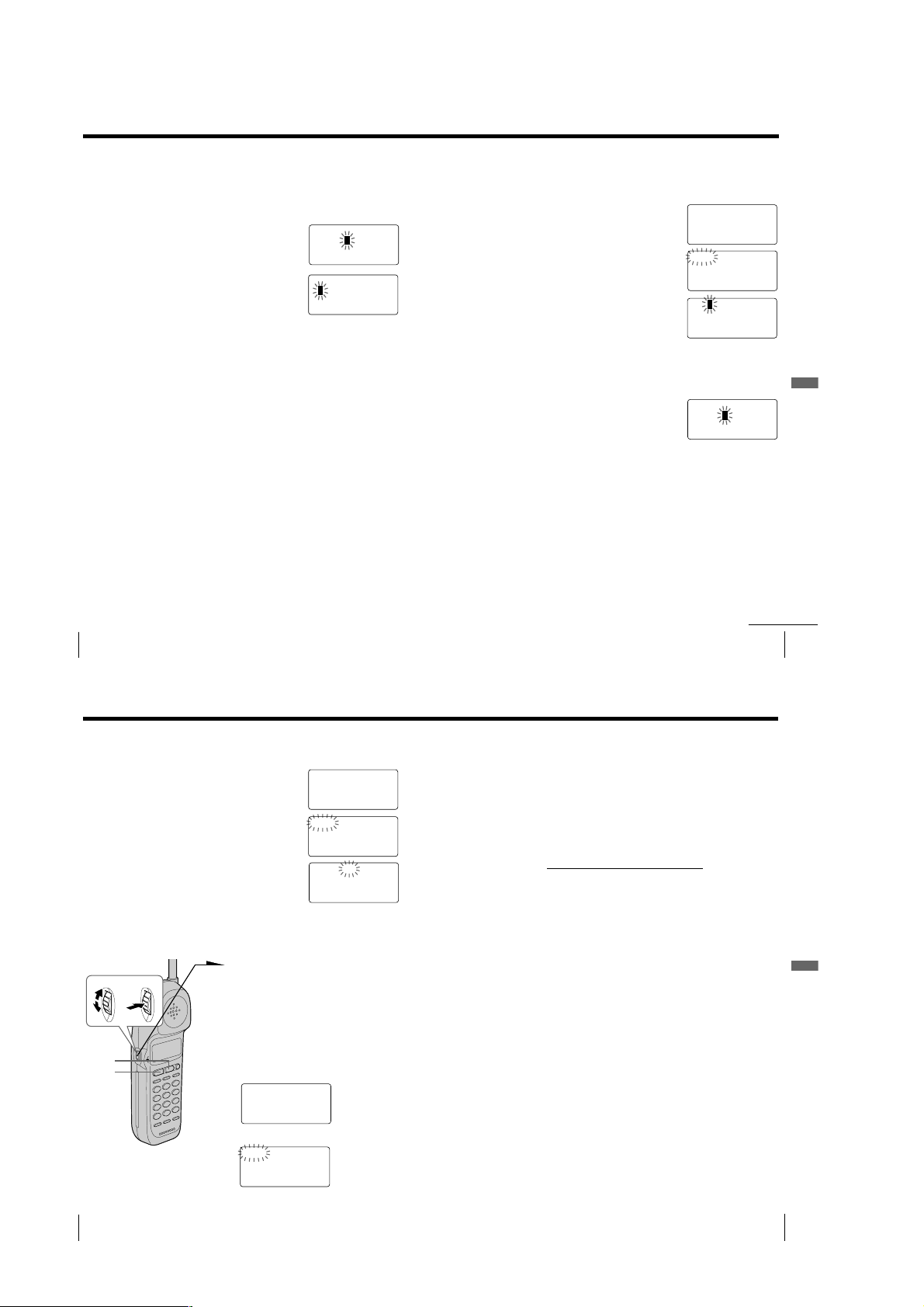
1 Open the battery compartment
lid of the base phone.
2 Insert the battery pack (with
contacts facing down) into the
battery compartment.
3 Close the battery compartment
lid.
The SPARE BATTERY lamp
lights up. Charge the battery
pack for more than 24 hours so
that the battery is fully charged.
The SPARE BATTERY lamp
remains lit even after charging
is completed.
US
16
BP-T23
SPARE BATTERY lamp
Getting Started
Step 4
Entering the area code
When you use this phone for the first time, or move to an area that has a
different area code, you must enter your home area code. Otherwise, you
cannot use some functions of this phone and the Caller ID functions.
This is also necessary because the phone must be able to select an area code to
properly dial call from the Caller ID list.
Depending on your region, enter 3-digit area code as follows:
Case 1.
If 7-digit dialing (no area code) is accepted for local calls in your area, see “To enter
your home area code” below.
If you live in an area where calls from or to other local areas can also be made by 10-digit dialing
(area code + number), you can register up to 5 local area codes with this telephone to take
advantage of this system. See “To enter the local area code (For 10 digits phone number users)”
on page 18.
Case 2.
If 10-digit dialing (area code + number) is required for all local calls in your area, at
first, enter “000” in your home area code. See “To enter your home area code” below.
Then see “To enter the local area code (For 10 digits phone number users)” on page
18.
To enter your home area code
1 Press (PGM).
Turn Press
2 Turn Jog Dial up to make “AREA”
flash.
DIRECTORY AREA
RINGER
3 Press Jog Dial.
HOME LOCAL
4 Press Jog Dial again.
“ENTER AREA CODE” appears on
the display.
continued
Getting Started
Getting Started
US
17
– 5 –
Page 6
Step 4: Entering the area code (continued)
5 Enter three digits of your home area code using the dialing keys.
6 Press (PGM).
You will hear a long confirmation beep.
Notes
• If the home area code is already entered, it appears on the display in step 4. To enter a
different home area code, see “To change the home area code” below.
• Do not allow more than 20 seconds to elapse between each step of the procedure.
Tips
• You may press Jog Dial instead of (PGM) in step 6.
• To check the current home area code, perform steps 1 to 4. The home area code appears on the
display for about 20 seconds.
To change the home area code
1 Perform steps 1 to 4 on page 17.
The current home area code appears on the display.
2 Turn Jog Dial down to erase the current home area code.
3 Enter a new home area code using the dialing keys.
4 Press (PGM).
You will hear a long confirmation beep.
To enter the local area code (For 10 digits phone
numbers users)
If a call matches one of the local area codes you entered, the phone number will be
registered with 10 digits in the Caller ID list (area code + number). If a call does not
match one of the local area codes you entered, the phone number will be registered
with 11 digits in the Caller ID list (1 + area code + number). Some regions of the
country allow you to have more than one local area code. (Up to five local area codes
can be entered in this phone.)
4 Select the number (”#1“ to ”#5“) to enter the
local area code by turning Jog Dial.
5 Press Jog Dial.
”ENTER AREA CODE“ appears on the display.
6 Enter three digits of the local area code using the dialing
keys.
7 Press (PGM).
You will hear a long confirmation beep.
Notes
• If the local area code is already entered, it appears on the display in step 5. To
enter a different local area code, see “To change the local area code” below.
• Do not allow more than 20 seconds to elapse between each step of the
procedure.
Tips
• You may press Jog Dial instead of (PGM) in step 7.
• To check the current local area code, perform steps 1 to 5. The local area code
appears on the display for about 20 seconds.
To change the local area code
1 Perform steps 1 to 5 on pages 18 to 19.
The current local area code appears on the display.
2 Turn Jog Dial down to erase the current local area code.
3 Enter a new local area code using the dialing keys.
4 Press (PGM).
You will hear a long confirmation beep.
Getting Started
1 Perform steps 1 to 3 on page 17.
2 Turn Jog Dial up to make ”LOCAL“ flash.
3 Press Jog Dial.
US
Getting Started
18
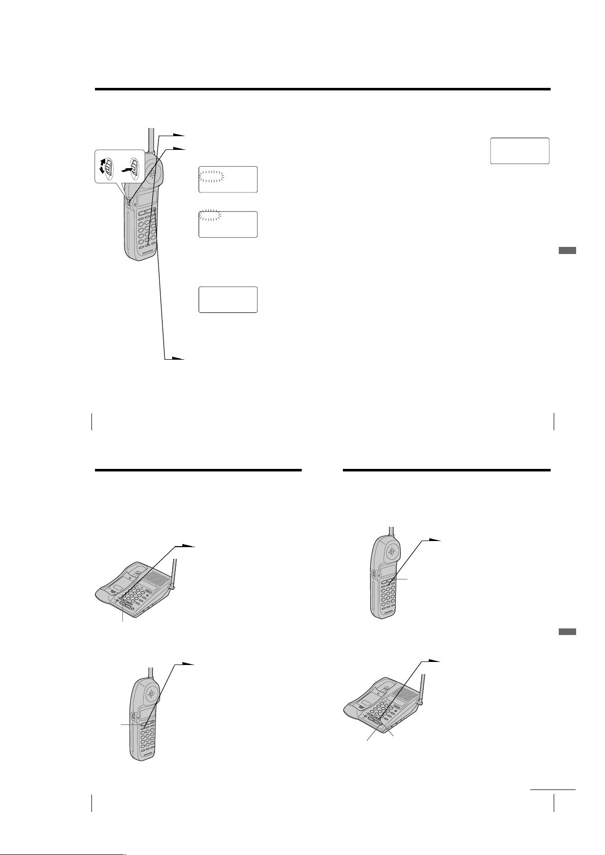
Basics
Making calls
I (HEADSET)
jack
(HOLD)
(*TONE)
(REDIAL/PAUSE)
VOL switch
HOME LOCAL
#1 #2 #3 #4 #5
1 Pick up the handset from the
base phone.
2 Press (LINE 1) or (LINE 2) to
select the line.
The corresponding line button
lights up.
“TALK” appears on the display
and the display also shows the
talk time in hours, minutes and
seconds.
You will then hear a dial tone.
“HANDSET IN USE” appears
on the display of the base phone
and the line button on the base
phone double flashes in
succession.
If “CHANNEL SEARCHING...”
appears on the display, move
closer to the base phone.
3 Dial the phone number.
4 When you’re done talking, press
(OFF) or replace the handset on
the base phone.
The display and the LINE 1 or
LINE 2 button go off.
To erase the local area code
You can erase the local area code. Perform steps 1 and 2 above, then
press (PGM).
The local area code will be erased, and you will hear a long
confirmation beep.
Making calls when the headset is connected
When the TL-HD1 headset (not supplied) is connected to the I
(HEADSET) jack, you can talk through the headset.
Precaution
Avoid listening your headset at so loud a volume that extended play might
affect your hearing.
Additional tasks
To
Adjust the handset volume
Put a call on hold
Switch to tone dialing
temporarily
Notes
• When you increase the sound volume, in some cases the back ground noise
may be increased as well. You should adjust the volume accordingly.
• If your conversation is muted and “CHANNEL SEARCHING...” appears on
the display, move closer to the base phone; otherwise, the call will be
disconnected after one minute.
Tips
• If you pick up another phone connected to the same phone line, the hold will
be automatically released and you will be able to resume conversation on
that phone.
• The LINE 1 or LINE 2 button on the handset double flashes in succession,
when the base phone is used. If you press (LINE 1) or (LINE 2) whichever
button is flashing, you can talk to the base phone and to the line connected.
Do this
Set the VOL switch to H (high), M (middle) or L
(low).
Press (HOLD).
The LINE 1 or LINE 2 button will flash slowly.
Press (LINE 1) or (LINE 2) to resume the
conversation.
Press (*TONE) after you’re connected.
The line will remain in tone dialing until
disconnected.
Getting Started
US
19
Basics
US
Basics
24
continued
Basics 25
US
– 6 –
Page 7
Making calls (continued)
If the battery becomes weak during a call
The handset will beep every three seconds five times and E and
“BATTERY LOW” appears on the display. Finish your call and charge
the battery pack.
For optimum performance, charge the battery for a full 12 hours.
Note that during the first 10 - 15 minutes of charging, the phone will be
inactive, i.e., unable to make or receive a call.
After this initial 10 - 15 minutes, you may be able to use the phone, but
the battery duration will be very short; thus it is recommended that
you fully charge the battery before the next usage.
If you have a spare battery
You can replace the battery pack without disconnecting the call during
a conversation. To replace the battery pack, perform the following
procedure.
1 Press (HOLD) on the handset.
The call is on hold and “HOLD” appears on the display.
2 Replace the battery pack.
3 Press (LINE 1) or (LINE 2) to resume the conversation.
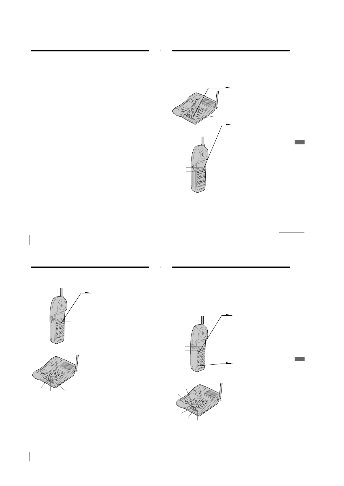
Making calls through the speakerphone
Press (LINE 1) or (LINE 2) on the base
phone.
“SPEAKERPHONE” appears on the
display and the display also shows the talk
time in hours, minutes and seconds.
The corresponding line button lights up.
Dial the phone number.
To adjust the speaker volume, press
(VOLUME)(+) or (--). Each press of
(VOLUME)(+) or (--) switches the speaker
volume by one of 8 levels.
To mute your voice, press (MUTING) to
disable the microphone. The MUTING
lamp lights up. Press (MUTING) again to
cancel.
When you’re done talking, press (OFF).
Notes
• The LINE 1 or LINE 2 button on the base phone double flashes in succession
and the display on the base phone shows “HANDSET IN USE”, when the
handset is used. If you press (LINE 1) or (LINE 2) whichever button is
flashing, you can talk to the handset and to the line connected.
• When the talk time exceeds 9:59’59, the display counts from 0:00’00 again.
To obtain the best speakerphone performance
• You may not be able to hear the other party’s voice in a noisy place.
Therefore, use the speakerphone in a quiet room.
• Do not bring your hand or other object too close to the microphone
or you will hear a shrill noise (“feedback”).
• When the speaker volume is loud, or the base phone has been placed
close to a wall, you may find that the volume drops suddenly. This
is due to a circuit in the telephone designed to protect against
feedback. In such cases, lower the speaker volume slightly.
(LINE 1)
(MUTING)
MUTING
lamp
(LINE 2)
(VOLUME)
(REDIAL/PAUSE)
(OFF)
Basics
US
Basics
26
Making calls (continued)
Redialing
1 Press (LINE 1) or (LINE 2) to select the line.
The corresponding line button lights up.
2 Press (REDIAL/PAUSE) to redial the last number dialed.
Note
If the number exceeds 32 digits or if it is erased, five short error beeps will alert
you that the number cannot be redialed.
Tip
The number to be redialed is the last number dialed either on the handset or on
the base phone.
To check the phone number before redialing
While either the handset or base phone is not in use, press
(REDIAL/PAUSE).
The last number dialed is displayed for five seconds.
To dial the number, press (LINE 1) or (LINE 2) while the number is
displayed.
Note
The number will not be displayed if the last number dialed exceeds 32 digits or
if it is erased.
To erase the last phone number dialed
While either the handset or base phone is not in use, press
(REDIAL/PAUSE) twice within five seconds.
The number will be erased from the memory, and you will hear a long
confirmation beep.
Making another call while talking
Example: Making a call on line 2 while talking on line 1
1 Press (HOLD) while talking.
The line 1 is put on hold and the LINE 1 button flashes
slowly.
2 Press (LINE 2).
3 Dial a phone number for the second party.
Now you can talk to the second party on line 2.
4 To put on hold line 2 and resume the conversation on line 1,
press (HOLD), and then (LINE 1).
To disconnect line 2 and resume the conversation on line 1,
press (LINE 1).
Note
If you do not press (HOLD) in step 1, line 1 will be disconnected.
You can talk with two parties at the same time using both line 1 and
line 2, see “Having a conference call” on page 49.
or
continued
Basics 27
US
Basics
US
Basics
28
Basics 29
US
– 7 –
Page 8
Receiving calls
1 When you hear the phone ring, press
(LINE 1) or (LINE 2) whichever button
is flashing.
The corresponding line button lights
up.
“TALK” appears on the display and
I (HEADSET)
jack
(HOLD)
VOL switch
(FLASH/CALL WAITING)
Receiving calls when the headset is connected
When the TL-HD1 headset (not supplied) is connected to the I
(HEADSET) jack, you can talk through the headset.
Precaution
Avoid listening your headset at so loud a volume that extended play might
affect your hearing.
Additional tasks
To
Adjust the handset volume
Put a call on hold
Switch to another call
(“call waiting” service*)
Turn on/off the ringer of
the handset
* You need to subscribe to the service from your telephone company.
US
Basics
30
Do this
Set the VOL switch to H (high), M (middle) or L
(low).
Press (HOLD).
The LINE 1 or LINE 2 button will flash slowly.
Press (LINE 1) or (LINE 2) to resume the
conversation.
Press (FLASH/CALL WAITING).
Press (FLASH/CALL WAITING) again to return to the
first caller.
See “Turning off the ringer of the handset” on
page 43.
the display also shows the talk time in
hours, minutes and seconds.
“HANDSET IN USE” appears on the
display of the base phone and the line
button on the base phone double
flashes in succession.
2 When you’re done talking, press
(OFF) or replace the handset on the
base phone.
The display and the LINE 1 or LINE 2
button go off.
Note
If another call comes in by “call waiting” service while conversing with an
outside caller, you will hear two short beeps.
Tip
To inform you of an incoming call, the display shows “** RINGING **” when
ringing.
If you have subscribed to the Caller ID service;
• the caller’s number and/or name appears on the display when you receive a
call (see page 52) or when another call comes in by “call waiting” service.
• the ringer sound changes to a higher tone if the call matches the number
stored on speed dialing keys or in the Phone Directory (memory match
function; see page 52).
Receiving calls through the speakerphone
When you hear the phone ring, press
(LINE 1) or (LINE 2) whichever button is
flashing.
“SPEAKERPHONE” appears on the display
and the display also shows the talk time in
hours, minutes and seconds.
The corresponding line button lights up.
When you’re done talking, press (OFF).
To obtain the best speakerphone performance,
see page 27.
(HOLD)
(LINE 1)
(MUTING)
MUTING
lamp
(LINE 2)
(OFF)
(VOLUME)
(FLASH)
L1 and L2 RINGER
LEVEL switches
continued
Basics 31
Basics
US
Receiving calls (continued)
Additional tasks
To
Adjust the speaker volume
Adjust the ringer volume of
the base phone
Put a call on hold
Mute your voice
Switch to another call
(“call waiting” service*)
* You need to subscribe to the service from your telephone company.
Note
Even when you set the L1 or L2 RINGER LEVEL switch on the base phone to
OFF, the handset will ring when the ringer of the handset is turned on (see page
43).
Tips
• To inform you of an incoming call, the display shows “** RINGING **”
and the line button lights on and off according to the ring signal even when
you set the L1 or L2 RINGER LEVEL switch on the base phone to OFF.
• If there is an incoming call while on the intercom, the base phone will ring at
a low level even when the L1 or L2 RINGER LEVEL switch on the base phone
is set to OFF.
Do this
During speakerphone conversation, press
(VOLUME)(+) or (--). Each press of
(VOLUME)(+) or (--) switches the speaker
volume by one of 8 levels.
You can adjust the ringer volume of line 1 and 2
respectively.
Set the L1 or L2 RINGER LEVEL switch on the
base phone to HIGH, LOW or OFF.
Press (HOLD).
The LINE 1 or LINE 2 button will flash slowly.
Press (LINE 1) or (LINE 2) to resume the
conversation.
Press (MUTING) to disable the microphone.
The MUTING lamp lights up.
Press (MUTING) again to cancel.
Press (FLASH).
Press (FLASH) again to return to the first caller.
Receiving a call while talking
If another call comes in while talking on the other line, the
corresponding line button will flash.
Example: Receiving a call on line 2 while talking on line 1
1 Press (HOLD) while talking.
The line 1 is put on hold and the LINE 1 button flashes
slowly.
2 Press (LINE 2).
Now you can talk to another caller on line 2.
3 To put on hold line 2 and resume the conversation on line 1,
press (HOLD), and then (LINE 1).
To disconnect line 2 and resume the conversation on line 1,
press (LINE 1).
Notes
• If you do not press (HOLD) in step 1, line 1 will be disconnected.
• If another call comes in while talking on the base phone, a beep will be heard
through the base phone and the corresponding line button on the base phone
will flash.
• If another call comes in while talking on the handset, a ringer tone will be
heard once through the handset and the corresponding line button on the
handset will flash. At this time, the base phone will ring and the
corresponding line button will flash normally.
You can talk with two parties at the same time using both line 1 and
line 2, see “Having a conference call” on page 49.
or
Basics
US
Basics
32
Basics 33
US
– 8 –
Page 9
Telephone Features
Speed dialing
You can dial with a touch of a few keys by storing a phone number on
a dialing key.
Storing phone numbers
and names
Example: to store “SONY” “123-4567”.
1 Press (PGM).
“PROGRAM” appears on the display.
2 Press (SPEED DIAL).
“ENTER 0 TO 9” appears on the
display.
3 Press one of the dialing keys ((0) to
(9)) to store a phone number on.
ENTER NAME
You will hear a confirmation beep.
4 Enter the name using the dialing keys.
You can enter up to 16 characters.
Press a dialing key until the desired
character appears. (See the character
table for details.)
Enter successive characters in the same
way.
To enter two characters assigned to the
same key, or to enter a “space”, press
(VOLUME)(+) to move the cursor to
the right.
Example: to enter “SONY”, press (7)
four times (S), press (6) three times
(O), press (VOLUME)(+) to move the
cursor, press (6) twice (N), and press
(9) three times (Y).
SONY
(LINE 1)
(LINE 2)
Character table
Key Character
(1) 1
(2) A t B t C t 2
(3) D t E t F t 3
(4) G t H t I t 4
(5) J t K t L t 5
(6) M t N t O t 6
(7) P t Q t R t S t 7
(8) T t U t V t 8
(9) W t X t Y t Z t 9
(0) 0
(*) *
(#) & t ’ t , t – t . t #
US
Telephone Features
34
(VOLUME)
(REDIAL/PAUSE)
5 Press (PGM).
“ENTER NUMBER” appears.
6 Enter the phone number.
You can enter up to 32 digits, including a tone
and a pause, each of which is counted as one
digit.
When the phone number of 17 digits or more
has been entered , the phone number appears in
two lines.
SONY
123456
1234567890123456
1
2
7 Press (PGM).
You will hear a long confirmation beep, and the
name and the number are stored. The display
goes off.
Note
Do not allow more than 20 seconds to elapse between each step of the
procedure.
Tip
If you have entered a wrong name or number in step 4 or 6, press
(VOLUME)(--) to erase it. Then enter the correct name or number.
To store a number to be dialed via Private Branch Exchange
(PBX)
Before entering a phone number in step 6 above, do as follows:
1 Enter the outside line access digit (e.g., 9).
2 Press (REDIAL/PAUSE).
To change a stored number
Store a new number, as described previously.
Telephone Features
7
Telephone Features
continued
US
35
Speed dialing (continued)
Making calls with speed dialing
1 Press (LINE 1) or (LINE 2) to select the line.
2 Press (SPEED DIAL).
3 Enter the desired speed dialing number ((0) to (9)).
The phone number stored as the speed dialing number will
be dialed.
To check the phone number before speed dialing
When not making a call with the base phone, press (SPEED DIAL) and
then one of the dialing keys ((0) to (9)).
The number stored on the key appears on the display for five seconds.
To dial the number, press (LINE 1) or (LINE 2) while the number is
displayed.
US
Telephone Features
36
Phone Directory
You can dial a number by scrolling through the Phone Directory, in
which up to 50 phone numbers can be stored.
Storing phone numbers and names
Example: to store “SONY” “123-4567”.
Turn Press
1 Press (PGM).
(Be sure not to press (LINE 1) and
(LINE 2).)
DIRECTORY AREA
RINGER
If “DIRECTORY” is not flashing, turn
Jog Dial down to make it flash.
2 Press Jog Dial.
“ENTER NAME” appears.
(REDIAL/PAUSE)
Character table
Key Character
(1) 1
(2) A t B t C t 2
(3) D t E t F t 3
(4) G t H t I t 4
(5) J t K t L t 5
(6) M t N t O t 6
(7) P t Q t R t S t 7
(8) T t U t V t 8
(9) W t X t Y t Z t 9
(0) 0
(*) *
(#) & t ’ t , t – t . t #
3 Enter the name using the dialing keys.
You can enter up to 16 characters.
Press a dialing key until the desired
character appears. (See the character
table for details.)
Enter successive characters in the same
way.
To enter two characters assigned to the
same key, or to enter a “space”, turn
Jog Dial up to move the cursor to the
right.
Example: to enter “SONY”, press (7)
four times (S), press (6) three times
(O), turn Jog Dial up to move the
cursor, press (6) twice (N), and press
(9) three times (Y).
SONY
continued
Telephone Features
Telephone Features
US
37
– 9 –
Page 10
Phone Directory (continued)
4 Press (PGM).
“ENTER NUMBER” appears.
5 Enter the phone number.
You can enter up to 32 digits, including a tone
and a pause, each of which is counted as one
digit.
When the phone number of 17 digits or more
has been entered, the phone number appears in
two lines.
6 Press (PGM).
You will hear a long confirmation beep, and the
name and the number are stored. The display
goes off.
Notes
• If you intend to save a 51st phone number, you will hear five short error
beeps and “MEMORY FULL” will be displayed. You cannot store the phone
number. To store another phone number, erase one of the stored phone
numbers (see page 40).
• Do not allow more than 20 seconds to elapse between each step of the
procedure.
• The total number of phone numbers which can be stored into the Phone
Directory varies according to the number of digits of each phone number. If
all the phone numbers consist of up to 16 digits, you can store up to 50 phone
numbers. However, as the Phone Directory uses two-phone number memory
to store one phone number of 17 digits or more, the total number of phone
numbers which can be stored in the Phone Directory decreases two by two
every time you store a phone number of 17 digits or more.
Tips
• If you have entered a wrong name or number in step 3 or 5, turn Jog Dial
down to erase it. Then enter the correct name or number.
• You may press Jog Dial instead of (PGM) in steps 4 and 6.
To store a number to be dialed via Private Branch Exchange
(PBX)
Before entering a phone number in step 5 above, do as follows:
1 Enter the outside line access digit (e.g., 9).
2 Press (REDIAL/PAUSE).
US
Telephone Features
38
SONY
123456
7
1234567890123456
1
2
Changing a stored name and/or phone
number
1 Display the name and phone number you want
to change by doing steps 1 and 2 in “Making
calls from the Phone Directory” on page 40.
2 Press Jog Dial.
3 Turn Jog Dial up to make “EDIT” flash and
press Jog Dial.
The cursor flashes at the last character of the
name.
4 Turn Jog Dial down to erase the characters and
enter the new name.
If you want to change only the number, skip this
step.
5 Press Jog Dial.
The cursor flashes at the last digit of the phone
number.
6 Turn Jog Dial down to erase the number and
enter the new number.
If you don’t want to change the number, skip
this step.
SONY
1234567
DIAL EDIT ERASE
1234567
SON
1234567
SMITH
123456
7 Press Jog Dial.
You will hear a long confirmation beep and the
name and/or the number is changed.
Tip
When the phone number of 17 digits or more has been entered, “–” is displayed
next to 15th digit and then the all digits are displayed in two lines after about
two seconds.
Y
7
Telephone Features
continued
Telephone Features
US
39
Phone Directory (continued)
Erasing a memory location
1 Display the name and phone number you want
to erase by doing steps 1 and 2 in “Making calls
from the Phone Directory”.
2 Press Jog Dial.
3 Turn Jog Dial up to make “ERASE” flash and
press Jog Dial.
4 Turn Jog Dial up to make “YES” flash, then
press Jog Dial.
You hear a long confirmation beep and the memory location is erased.
SONY
1234567
DIAL EDIT ERASE
1234567
ERASE NO YES
1234567
Making calls from the Phone Directory
1 Press Jog Dial.
Turn Press
(LINE 2)
(LINE 1)
“DIRECTORY” appears on the
display.
2 Display the name and phone number
you want to call.
To search in alphabetical order: Turn
Jog Dial up or down.
To search by entering the initial
character: Press the dialing key of the
desired character, then turn Jog Dial.
SONY
1234567
3 Press Jog Dial.
DIAL EDIT ERASE
1234567
Tips
• You may press (LINE 1) or (LINE 2) to make a call instead of doing steps 3
and 4.
• When you press Jog Dial in step 4, the vacant line is automatically connected.
When neither line is in use, line 1 is connected.
About the search order
The names appear in the following order when you turn Jog Dial up or
down.
• Alphabetical order: ABC...XYZ y symbols y * y # y 0 - 9
• Initial character: To search for “SONY” for example, press (7) and
then turn Jog Dial to search through the names starting with P, Q, R,
S or 7.
t
t
Telephone Features
US
Telephone Features
40
4 Press Jog Dial again.
The phone number will be dialed.
– 10 –
Telephone Features
US
41
Page 11
Setting the ringer type
You can select a ringer type of the handset from four type.
1 Press (PGM).
Turn Press
2 Turn Jog Dial up to make “RINGER”
flash.
DIRECTORY AREA
RINGER
3 Press Jog Dial.
LINE1 LINE2
Turning off the ringer of the handset
1 Perform steps 1 to 5 on page 42.
2 Press (0).
You will hear a confirmation beep.
3 Press (OFF).
When “RINGER” is set to “RINGER OFF”
The handset won’t ring. You can still make calls, and also receive
calls if another telephone connected to the same line rings to inform
you on incoming calls.
To turn the ringer on again
Follow the instructions described in “Setting the ringer type” on
page 42.
RINGER OFF
SELECTED
4 Turn Jog Dial to choose the line you
want to set the ringer type.
5 Press Jog Dial.
The current ringer type appears.
RINGER 1
SELECTED
6 Press one of the dialing keys ((1) to
(4)) to select a ringer type.
You will hear the corresponding ringer
tone.
7 Press (OFF).
US
Telephone Features
42
Switching the phones during a call
You can easily switch between the handset and speakerphone on the
base phone without disconnecting the call. The call on line 1 will be
switched to line 1 on another phone and that on line 2 is switched to
line 2.
To switch from the base phone to the handset
Example: While talking on line 1:
1 Press (HOLD) on the base phone.
The call is on hold and “HOLD”
appears on the display and the
LINE 1 button flashes slowly.
2 Press (LINE 1) on the handset.
The LINE 1 button on the handset
lights up and the LINE 1 button on
the base phone double flashes in
(LINE 1)
succession.
You can continue talking to the
caller through the handset.
To switch from the handset to the base phone
Example: While talking on line 1:
1 Press (HOLD) on the handset.
The call is on hold and “HOLD”
appears on the display and the
LINE 1 button flashes slowly.
2 Press (LINE 1) on the base phone.
The LINE 1 button on the base
(LINE 1)
Tip
While talking through the speakerphone on the base phone (or handset), if you
press (LINE 1) or (LINE 2) which is flashing on the handset (or base phone), you
can talk to the base phone (or handset) and to the line connected.
US
Telephone Features
44
phone lights up and the LINE 1
button on the handset double
flashes in succession.
You can continue talking to the
caller through the speakerphone.
Telephone Features
Talking between the phones (Intercom)
You can converse using the base phone and the handset. You can start
the intercom from either phone.
To talk from the handset to
the base phone
Press (INTERCOM) on the handset.
After the base phone rings twice, you
will be connected automatically.
When a person at the base phone
answers, you can talk with each other.
“INTERCOM” appears on the display
and the INTERCOM lamp on the base
phone lights up.
When you are done talking or if no
one answers the phone
Press (OFF) on the handset.
To talk from the base
phone to the handset
Press (INTERCOM) on the base phone.
The base phone and handset ring and
“** PAGING **” appears on the
display.
When a person at the handset presses
(INTERCOM), you can talk with each
other.
“INTERCOM” appears on the display
and the INTERCOM lamp on the base
phone lights up .
When you are done talking or if no
one answers the phone
Press (OFF) on the base phone.
continued
Telephone Features
(OFF)
(OFF)
INTERCOM lamp
Telephone Features
US
43
Telephone Features
US
45
– 11 –
Page 12
Talking between the phones (Intercom) (continued)
Note
While conversing with an outside caller via the base phone or handset, you
cannot make an intercom call. If you press (INTERCOM), you will hear a busy
tone.
Tips
• You can receive an intercom call on the handset even when “RINGER” is set
to “RINGER OFF”.
• You can receive an intercom call on the base phone even when the L1 or L2
RINGER LEVEL switch on the base phone is set to OFF. The base phone will
ring at a low level.
Receiving a call while using the intercom
When a call comes in, “** RINGING **” appears on the display and
only the base phone rings at a low level.
The LINE 1 or LINE 2 button flashes.
Press (LINE 1) or (LINE 2) whichever is flashing, then you can answer
the call.
US
Telephone Features
46
Transferring a call
You can transfer a call between the handset and base phone without
disconnecting the call.
To transfer from the base phone to the handset
1 Press (INTERCOM) to page the
handset.
The call is put on hold on the
base phone and the handset
rings.
“** PAGING **” appears on
(OFF)
INTERCOM lamp
(LINE 2)
(LINE 1)
Tips
• You can receive an intercom call on the handset even when “RINGER” is set
to “RINGER OFF”.
• If you have accidentally pressed (HOLD) in step 1, just press (INTERCOM)
and you will get the same result as by pressing (INTERCOM) only.
the display of both the base
phone and handset.
2 Press (INTERCOM) on the
handset.
“INTERCOM” appears on the
display of both the handset and
base phone and the INTERCOM
lamp on the base phone lights
up.
You can talk between the base
phone and the handset.
3 Press (LINE 1) or (LINE 2)
which is flashing on the handset
to talk to the caller with the
handset.
“TALK” appears on the display
of the handset.
If no one answers the phone
Press (OFF) on the base phone.
Telephone Features
continued
Telephone Features
US
47
Transferring a call (continued)
To transfer from the handset to the base phone
1 Press (INTERCOM) to page the
base phone.
The call is put on hold on the
handset.
After the base phone rings
twice, you will be connected
(OFF)
(LINE 1)
(LINE 2)
INTERCOM lamp
Tip
You can receive an intercom call on the base phone even when the L1 or L2
RINGER LEVEL switch on the base phone is set to OFF. The base phone will
ring at a low level.
automatically.
When a person at the base
phone answers, you can talk
with each other.
“INTERCOM” appears on the
display of both the base phone
and handset and the
INTERCOM lamp on the base
phone lights up.
2 Press (LINE 1) or (LINE 2)
which is flashing on the base
phone to talk to the caller with
the base phone.
“SPEAKERPHONE” appears on
the display of the base phone.
If no one answers the phone
Press (OFF) on the handset.
Having a conference call
You can talk on two lines at the same time and you can also talk on one
line, the handset and the base phone at the same time.
Making another call while talking
You can talk with two parties at the same time using both line 1 and
line 2. (Three-way conference)
1 Press (HOLD) while talking on
one line.
The line in use is put on hold.
2 Press (LINE 1) or (LINE 2),
whichever is not used.
(LINE 2)
(LINE 1)
(HOLD)
(LINE 1)
(CONF)
(LINE 2)
(OFF)
(OFF)
3 Dial a phone number for the
second party.
4 Press (CONF) (conference) after
the second party is connected.
“CONFERENCE” appears on
the display.
Now you can talk to both
parties.
Telephone Features
US
Telephone Features
48
– 12 –
continued
Telephone Features
US
49
Page 13
Having a conference call (continued)
Receiving a call while talking
If another call comes in while talking, the LINE 1 or LINE 2 button on
which another call is coming will flash.
1 Press (HOLD).
The line in use is put on hold.
2 Press (LINE 1) or (LINE 2), on which another call is coming.
3 Press (CONF) (conference).
Now you can talk to both parties. (Three-way conference)
Note
If you do not press (HOLD) in step 1, the first line will be disconnected.
To disconnect the lines during a three-way conference
To disconnect both lines at the same time, press (OFF).
To disconnect line 1 and talk on line 2 only:
Press (LINE 2).
To disconnect line 2 and talk on line 1 only:
Press (LINE 1).
To put the lines on hold during a three-way conference
Press (HOLD). Both lines are put on hold.
To resume the conversations on both lines:
Press (CONF).
To resume the conversation only on one line:
Press (LINE 1) or (LINE 2), for the line you want. (The other line is kept
on hold.)
Tip
During a three-way conference, you cannot use “call waiting” service even if
you press (FLASH/CALL WAITING) or (FLASH).
Switching conference from the handset to
the base phone
1 Press (HOLD) on the handset to put both lines on hold.
The LINE 1 and LINE 2 buttons on the handset and the base
phone flash.
2 Press (CONF) on the base phone to resume the conversation.
Switching conference from the base phone
to the handset
1 Press (HOLD) on the base phone to put both lines on hold.
The LINE 1 and LINE 2 buttons on the base phone and the
handset flash.
2 Press (CONF) on the handset to resume the conversation.
To join on the base phone while the handset
is talking on one line
Press the double flashing (LINE 1) or (LINE 2) on the base
phone. Now you can talk to the handset and to the line
connected.
To join on the handset while the base phone
is talking on one line
Press the double flashing (LINE 1) or (LINE 2) on the handset.
Now you can talk to the base phone and to the line connected.
To join three-way conference (four-way
conference)
Press (LINE 1) or (LINE 2).
Telephone Features
US
Telephone Features
50
Caller ID Features
Understanding the Caller ID service
Caller ID allows the caller’s phone number to be shown on the display
before the call is answered. In order to use this feature, you must first
subscribe to the Caller ID service. The name of this service may vary
depending on your telephone company.
To use this feature, be sure to enter your home area code (see page 17).
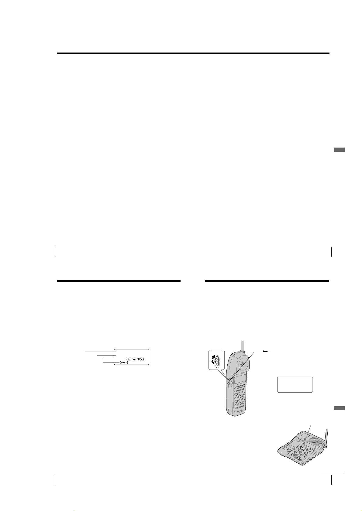
When you receive a call
The phone number appears on the display with the date and time* as
shown in the following example.
If your Caller ID service includes the caller name service, the caller’s
name also appears on the display (up to 15 letters).
Caller’s name
Caller’s phone number
The date and time received
The line which received the
Caller ID data
When you answer the call, the Caller ID display changes to the
“TALK” or “SPEAKERPHONE” display.
Notes
• The caller’s phone number and/or name will not appear in the following cases:
- “OUT OF AREA”: when the call is made through a telephone company which
does not offer Caller ID service (including international calls).
- “PRIVATE”: when the call is “blocked.” For privacy reasons, many states allow
callers the option to prevent his or her telephone data from being displayed on
the other party’s Caller ID display.
• If the call is from an office which uses multiple lines, the displayed phone number
may not match the number you use to call the extension.
Tips
• Even if the ringer of the handset is set to “RINGER OFF”, you can receive
Caller ID data.
• If a call comes in on both line 1 and 2 simultaneously, the display will show
the data on line 1 and 2 alternately.
About the memory match function
If you receive a call from a phone number which is stored on speed dialing
keys (see page 34) or in the Phone Directory (see page 37), the ringer sound
will change to a higher tone from the second ring.
Note
The memory match function does not work with “OUT OF AREA” or “PRIVATE”
calls; and it may not work with calls made from an office which uses multiple lines
because the number does not always match the one you stored in this phone.
US
Caller ID Features
52
Handset
SMITH JOHN
1-201-123-4567
* The display on the base phone
does not show the date and time.
Looking at the Caller ID list
The phone stores the data of the last 20 calls received including “OUT
OF AREA” and “PRIVATE” calls. It keeps track of all calls received;
even if they were not answered.
Viewing the Caller ID list
You can look through the Caller ID list to check the phone number
and/or name of the calls received on the handset’s display. Note that
the display on the base phone shows the current caller’s phone number
and/or name only, and you cannot view the caller ID list on the base
phone.
Turn
Note
If a 21st call is received, the oldest data is automatically
erased.
Tip
If there is a “NEW” data, the NEW CALL lamp of the
base phone flashes.
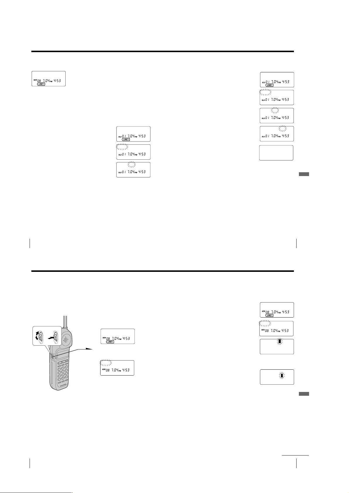
1 Turn Jog Dial.
The display shows the number
of “NEW” (calls which you have
not viewed) and “OLD” (calls
which you have viewed) calls.
NEW O8 OLD 12
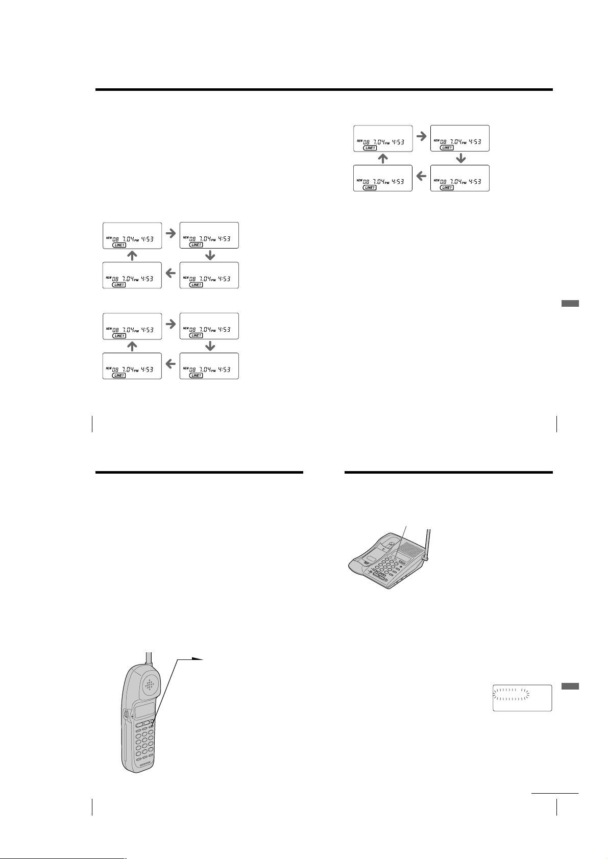
2 Turn Jog Dial down to display
older data or up to display
newer data.
Telephone Features
NEW CALL lamp
continued
Caller ID Features
US
51
Caller ID Features
US
53
– 13 –
Page 14
Looking at the Caller ID list (continued)
SMITH JOHN
1201123456
7
SMITH JOHN
1-201-123-4567
About the “*” mark
SMITH JOHN *
1-201-123-4567
“*” appears if there are more than two calls
from the same phone number. The older data
will be replaced by the new data, so the calls
are counted as only one call.
Erasing data from the Caller ID list
Old data will be erased automatically when a 21st call comes in, but
you can also manually erase unnecessary data one by one or erase the
entire list.
To erase the phone number one by one
1 Display the phone number you want to erase
from the Caller ID list (see page 53).
2 Press Jog Dial.
3 Turn Jog Dial up to make “ERASE” flash and
press Jog Dial.
4 Turn Jog Dial up to make “YES” flash, then
press Jog Dial.
You will hear a long confirmation beep and the
data is erased.
SMITH JOHN
1-201-123-4567
DIAL PGM ERASE
1-201-123-4567
ERASE NO YES
1-201-123-4567
To erase the entire list at once
1 Display any Caller ID data.
2 Press Jog Dial.
3 Turn Jog Dial up to make “ERASE” flash and
press Jog Dial.
4 Turn Jog Dial up to make “ALL” flash, then
press Jog Dial.
5 Turn Jog Dial up to make “YES” flash, then
press Jog Dial.
You will hear a long confirmation beep and the
entire list is erased.
Note
“ALL” appears only when all the data has become “OLD” data. If there is any
“NEW” data, you cannot erase the entire list.
SMITH JOHN
1-201-123-4567
DIAL PGM ERASE
1-201-123-4567
ERASE NO YES ALL
1-201-123-4567
ALL ERASE NO YES
1-201-123-4567
NEW OO OLD OO
Caller ID Features
US
Caller ID Features
54
Using the Caller ID list
By using the Caller ID list, you can call back a phone number from the
Caller ID list easily, or store numbers from the Caller ID list into the
Phone Directory.
Calling back a number from the Caller ID list
1 Display the phone number you
want to call from the Caller ID
Turn Press
list (see page 53).
SMITH JOHN
1-201-123-4567
2 Confirm the number and press
Jog Dial.
DIAL PGM ERASE
1-201-123-4567
3 Press Jog Dial again.
The phone automatically dials
the displayed number.
Notes
• If the number displayed in step 1 is not the one you should call back, you can
change the number of digits of the phone number as described on page 58.
• If the phone is connected to a Private Branch Exchange (PBX), you may not
be able to call back from the Caller ID list because an outside line access digit
is necessary.
• When neither line is in use, line 1 is automatically connected in step 3. If you
want to select the line manually, press (LINE 1) or (LINE 2) after step 1. You
will then be connected to the line you have chosen.
Storing a number of the Caller ID list into
the Phone Directory
1 Display the name and phone number you want
to store from the Caller ID list (see page 53).
2 Confirm the number and press Jog Dial.
3 Turn Jog Dial up to make “PGM” flash and
press Jog Dial.
The cursor flashes at the end of the name.
Enter or change the name, if necessary (see page
39).
DIAL PGM ERASE
1-201-123-4567
SMITH JOH
12011234567
4 Press Jog Dial.
The cursor flashes at the end of the phone
number.
Enter or change the phone number, if necessary
(see page 39).
5 Press Jog Dial again.
You will hear a long confirmation beep and the
name and number are stored.
Notes
• Do not allow more than 20 seconds to elapse between each step of the
procedure.
• If the number displayed in step 1 is not the one you should store, you can
change the number of digits of the phone number as described on page 58.
• If the phone is connected to a Private Branch Exchange (PBX), you may need
to add an outside line access digit.
Caller ID Features
N
US
55
Caller ID Features
US
Caller ID Features
56
– 14 –
continued
Caller ID Features
US
57
Page 15
Using the Caller ID list (continued)
To change the number of digits of the phone
number
If the number of digits of the phone number in the Caller ID list is
different from the actual phone number, you need to adjust the
number of digits of the phone number to call back or store into the
Phone Directory .
1 While the phone number from the Caller ID list is displayed,
press (#) repeatedly until the phone number with the
correct number of digits appears on the display.
Each time you press (#), the number of digits changes as
follows.
When the home area code and the local area code do
not match
SMITH JOHN
1-201-123-4567
SMITH JOHN
123-4567
When the home area code matches
SMITH JOHN
123-4567
SMITH JOHN
1-123-4567
SMITH JOHN
201-123-4567
SMITH JOHN
1-123-4567
SMITH JOHN
1-201-123-4567
SMITH JOHN
201-123-4567
When the local area code matches
SMITH JOHN
201-123-4567
SMITH JOHN
1-201-123-4567
2 Continue the operation to call or store the phone number
with the correct number of digits (pages 56 and 57).
Notes
• You need to adjust the number of digits each time you call back from the
Caller ID list as the changes to the Caller ID data is not stored in memory.
• You may not be able to change the number of digits depending on the Caller
ID data.
SMITH JOHN
1-123-4567
SMITH JOHN
123-4567
Caller ID Features
US
Caller ID Features
58
Using “Caller ID with call waiting”
service
This telephone is compatible with the “Caller ID with call waiting”
service. Make sure that your telephone company offers this service.
Like the basic Caller ID service, you need to subscribe to “Caller ID
with call waiting” in order to use this service.
Even though you may have already subscribed to “Caller ID” and
“call waiting” as two separate services, you need to request a
subscription to “Caller ID with call waiting” as a single service.
This is a new service that combines the two services.
Even though you now have a “Caller ID with call waiting”
compatible phone, unless you subscribe to the combined “Caller ID
with call waiting” service, you will not be able to see the name
and number of the second caller.
When a new call comes in while you are talking, you hear two short
beeps. The caller’s name and/or phone number of the new call appears
on the display for about 20 seconds.
To switch to another caller
1 To switch to the new caller,
press (FLASH/CALL WAITING).
(If you’re at the base phone,
press (FLASH).)
2 To switch back to the first caller,
press (FLASH/CALL WAITING) (or
(FLASH)) again.
Caller ID Features
Using visual message waiting service
If you subscribe to your telephone company’s message service which
includes this feature, the display will show that you have messages
waiting to be retrieved.
MESSAGES lamp
Note
You cannot use this feature, if you have not subscribed to your telephone
company’s message service.
For details on the availability of this service, please ask your telephone
company.
If the MESSAGES lamp remains flashing
If this lamp does not go off (e.g. When you retrieve your messages
with other phones), you can go off the lamp manually.
To go off the MESSAGES lamp
1 Press (PGM) on the handset.
2 Press (#) on the handset.
3 Press Jog Dial.
The MESSAGES lamp on the base phone goes
off, and you will hear a long confirmation beep.
If you have messages
The MESSAGES lamp on the base phone
flashes.
The MESSAGES lamp will go off when you
retrieve your messages.
MESSAGES WAITING
LIGHT-OFF RESET
US
59
Caller ID Features
US
60
Caller ID Features
– 15 –
continued
Caller ID Features
US
61
Page 16

Using visual message waiting service (continued)
If you move or change your telephone company
Message waiting signals are sent in one of two ways: FSK signaling or
“stutter” signaling (Your telephone company can provide you with
more information about your service).
The first time this phone receives a voice mail message, it will set itself
to the FSK service and will lock out the stutter service if your
telephone company is in FSK service.
When you move or change your telephone company, you need to
perform the following procedure. The phone will returns to ready state
for either FSK or stutter dial tone voice mail recognition.
To reset this phone
1 Press (PGM) on the handset.
2 Press (#) on the handset.
3 Turn Jog Dial up to make “RESET” flash and
press Jog Dial.
You will hear a long confirmation beep and the
phone is reset.
MESSAGES WAITING
LIGHT-OFF RESET
US
62
Caller ID Features
– 16 –
Page 17

SECTION 2
2 two screws
(BVTP3 × 12)
1 Remove the “lid (hand), battery case”
in the direction of arrow A.
A
6 Remove the case (rear)
in the direction of arrow B.
B
5 claw
4 two claws
3 two claws
)
DISASSEMBLY
Note: Follow the disassembly procedure in the numerical order given.
CASE (REAR)
RF UNIT (HS), HAND MAIN BOARD
2 antenna
(ANT2)
5 RF unit (HS)
1 two screws
(BVTP3 × 12)
1 two screws
3
(2 × 10)
1 four screws
(2 × 8)
1 screw
(BVTP3 × 12
4 knob (HS), VOL
6 HAND MAIN board
– 17 –
Page 18

BASE (BOTTOM)
1 five screws
(BTP3 × 12)
2 claw
3 base (bottom)
2 claw
“ringer (SW), knob”,
“knob, TP SW”
S1001, S1002, S1003
NOTE: On installation BASE MAIN board, adjust to the S1001,
S1002 and the S1003.
BASE MAIN BOARD, RF UNIT (BASE)
1 three screws
(BVTP3 × 12)
2 harness
BASE MAIN board
3
RF UNIT (BASE)
– 18 –
Page 19

BASE KEY BOARD, SPEAKER (SP1)
S
1 four screws
4 bracket, SPK board
5 speaker (SP1),
“holder, speaker”
2 plate, shield
6 eghit screws
7
9 KEY board
8 contact-C, B/
3 Remove two solders
of lead.
– 19 –
Page 20

SECTION 3
ELECTRICAL ADJUSTMENTS
BASE UNIT
1. Test Mode
[Entering the Test Mode]
While pressing the [INTERCOM] key, turn the power ON, then
change over the [DIAL MODE] switch. When enter the test mode,
light up the [LINE1], [LINE2] and [CHARGE] LEDs.
[Releasing the Test Mode]
Press the [FLASH] key.
[Key Functions]
[MUTING] key :Toggle TX power.
[VOLUME +] key:Increment channel.
[VOLUME -] key :Decrement channel
[0] key :Clear all speed dial locations.
[HOLD] key : Light up the all LEDs and LCD back light (ex-
cept [CHARGE] and [SPARE BATTERY] LEDs)
L1 L2 TONE/ Audio
Activated RINGER RINGER PULSE Control
Switch Switch Switch
Idle OFF OFF PULSE None
Base Unit on L1,
L2 Idel
Base Unit on L2,
L1 Idel
Handset on L1,
Base Unit on L2 SPK2 EN
Handset on L2,
Base Unit on L1 SPK1 EN
Handset on L1
& L2 Conf CONF
Base Unit L1
& L2 Conf
Intercom OFF OFF TONE INT COM
Handset & Base
Unit Both on L1 INT COM
Handset & Base
Unit Both on L2 INT COM
4-way Conf HIGH HIGH TONE
Note:
HOOK SW1 & HOOK SW2 are logic “0” (hook switch (es) activated)
corresponding to the active line (s).
MIC MUTE & ASIC SPK MUTE are logic “0” (speakerphone IC & dri ver
enabled) when base speakerphone is activated.
T AD L2 is logic “1” (T AD audio O/P & I/P connected to L2) in the “Handset
on L1, L2 Idle” condition
TAD L1 & TAD L2 are logic “0” (TAD audio switches open) in all other
conditions.
HIGH OFF PULSE SPK1 EN
OFF HIGH PULSE SPK2 EN
LOW HIGH PULSE
HIGH LOW PULSE
LOW LOW PULSE
HIGH HIGH PULSE SPK2 EN,
HIGH OFF TONE
OFF HIGH TONE
L1 EN,
L2 EN,
L1 EN, L2 EN,
SPK1 EN,
CONF
L1 EN, SPK1 EN,
L2 EN, SPK2 EN,
L1 EN, L2 EN,
SPK1 EN,
SPK2 EN,
INT COM, CONF
2. Adjustment Equipment and Connection
frequency counter
+
–
– BASE MAIN BOARD
(Component Side) –
J1
RF UNIT
U1000
C1164
C1120 C1122
3. Check the 18.4 MHz Frequency Error
Procedure:
1. Enter the Test Mode.
2. Connect the frequency counter to the test point J1 on the RF
unit.
3. Press the [MUTING] key to turn on the TX power.
4. Check the frequency ± 1 kHz.
5. If the result is within ± 1 kHz then no alignment required.
Otherwise, refer to next item.
4. Adjustment the 18.4 MHz Frequency Error
Procedure:
1. Remove C1122 from the BASE MAIN board.
2. Solder on 20 PF variable capacitor C1164 (1-164-160-11) on
the BASE MAIN board (in parallel of C1120).
3. Enter the test mode.
4. Connect the frequency counter to the test point J1 on the RF
unit.
5. Press the [MUTING] key to turn on the TX power.
6. Adjust C1164 on the BASE MAIN board for 0 Hz ± 1kHz.
** FSK SEL is logic “1” (L1 FSK routed to External CID & L2 FSK
routed to ASIC) in the “Base Unit on L1, L2 Idle” condition.
FSK SEL is logic “0” (L2 FSK routed to External CID & L1 FSK
routed to ASIC) in all other conditions.
– 20 –
Page 21

HANDSET
1. Test Mode
[Entering the Test Mode]
1. Press the [PGM] key, then displayed “DIRECTORY AREA
RINGER” on the LCD.
2. Press the [*], [*], [8], [3], [7], [8] keys, then displayed on
the LCD as below.
LCD display
**Test Mode**
TxPwr:_ Ch:05
NEW
OLD
LINE1 LINE2
[Releasing the Test Mode]
Press the [OFF] key.
[Key Functions]
[7] key: LCD test
LCD display
E
2. Adjustment Equipment and Connection
frequency counter
+
–
– HAND MAIN BOARD
(Component Side) –
J1
RF UNIT
C1057
C1031
C1029
[0] key: Toggle TX power.
LCD display
**Test Mode**
NEW
OLD
LINE1 LINE2
# key : Increment RF channel.
LCD display
E
**Test Mode**
TxPwr:_ Ch:05
NEW
OLD
LINE1 LINE2
Increases the channel number
E
U1001
3. Check the 18.4 MHz Frequency Error
Procedure:
1. Enter the test mode.
2. Connect the frequency counter to the test point J1 on the RF
unit.
3. Press the
4. Check the frequency ± 1 kHz.
5. If the resuit is with in ± 1 kHz, then no alignment required.
Otherwise, refer to next item.
4. Adjustment the 18.4 MHz Frequency Error.
Procedure:
1. Remove C1031 from the HAND MAIN board.
2. Solder on 20 PF variable capacitor C1057 (1-164-160-11) on
the HAND MAIN board. (in parallel of C1029).
3. Enter the test mode.
4. Connect the frequency counter to the test point J1 on the RF
unit.
5. Press the [0] key to turn on the TX power.
6. Adjust C1057 on the HAND MAIN board for 0 Hz ± 1 kHz.
[0] key to turn on the TX power.
– 21 –
Page 22

• Frequency Allocation Tables
The RF channels for the SPP-IM977 are allocated in fixed pairs as
indicated in the tables below. The duplex frequency is maintained
at 22.75 MHz for 19 of the 30 channels and 17.95 MHz for the
remaining 11 channels.
Base Unit Frequencies
Channel
1 902.30 MHz 925.05 MHz 914.35 MHz
2 902.45 MHz 925.20 MHz 914.50 MHz
3 902.60 MHz 925.35 MHz 914.65 MHz
4 902.75 MHz 925.50 MHz 914.80 MHz
5 902.90 MHz 925.65 MHz 914.95 MHz
6 903.05 MHz 925.80 MHz 915.10 MHz
7 903.20 MHz 925.95 MHz 915.25 MHz
8 903.35 MHz 926.10 MHz 915.40 MHz
9 903.50 MHz 926.25 MHz 915.55 MHz
10 903.65 MHz 926.40 MHz 915.70 MHz
11 903.80 MHz 926.55 MHz 915.85 MHz
12 903.95 MHz 926.70 MHz 916.00 MHz
13 904.10 MHz 926.85 MHz 916.15 MHz
14 904.25 MHz 927.00 MHz 916.30 MHz
15 904.40 MHz 927.15 MHz 916.45 MHz
16 904.55 MHz 927.30 MHz 916.60 MHz
17 904.70 MHz 927.45 MHz 916.75 MHz
18 904.85 MHz 927.60 MHz 916.90 MHz
19 905.00 MHz 927.75 MHz 917.05 MHz
20 905.15 MHz 923.10 MHz 912.40 MHz
21 905.30 MHz 923.25 MHz 912.55 MHz
22 905.45 MHz 923.40 MHz 912.70 MHz
23 905.60 MHz 923.55 MHz 912.85 MHz
24 905.75 MHz 923.70 MHz 913.00 MHz
25 905.90 MHz 923.85 MHz 913.15 MHz
26 906.05 MHz 924.00 MHz 913.30 MHz
27 906.20 MHz 924.15 MHz 913.45 MHz
28 906.35 MHz 924.30 MHz 913.60 MHz
29 906.50 MHz 924.45 MHz 913.75 MHz
30 906.65 MHz 924.60 MHz 913.90 MHz
Transmit Receive RX LO
Frequency Frequency Frequency
Handset Frequencies
Channel
1 925.05 MHz 902.30 MHz 913.00 MHz
2 925.20 MHz 902.45 MHz 913.15 MHz
3 925.35 MHz 902.60 MHz 913.30 MHz
4 925.50 MHz 902.75 MHz 913.45 MHz
5 925.65 MHz 902.90 MHz 913.60 MHz
6 925.80 MHz 903.05 MHz 913.75 MHz
7 925.95 MHz 903.20 MHz 913.90 MHz
8 926.10 MHz 903.35 MHz 914.05 MHz
9 926.25 MHz 903.50 MHz 914.20 MHz
10 926.40 MHz 903.65 MHz 914.35 MHz
11 926.55 MHz 903.80 MHz 914.50 MHz
12 926.70 MHz 903.95 MHz 914.65 MHz
13 926.85 MHz 904.10 MHz 914.80 MHz
14 927.00 MHz 904.25 MHz 914.95 MHz
15 927.15 MHz 904.40 MHz 915.10 MHz
16 927.30 MHz 904.55 MHz 915.25 MHz
17 927.45 MHz 904.70 MHz 915.40 MHz
18 927.60 MHz 904.85 MHz 915.55 MHz
19 927.75 MHz 905.00 MHz 915.70 MHz
20 923.10 MHz 905.15 MHz 915.85 MHz
21 923.25 MHz 905.30 MHz 916.00 MHz
22 923.40 MHz 905.45 MHz 916.15 MHz
23 923.55 MHz 905.60 MHz 916.30 MHz
24 923.70 MHz 905.75 MHz 916.45 MHz
25 923.85 MHz 905.90 MHz 916.60 MHz
26 924.00 MHz 906.05 MHz 916.75 MHz
27 924.15 MHz 906.20 MHz 916.90 MHz
28 924.30 MHz 906.35 MHz 917.05 MHz
29 924.45 MHz 906.50 MHz 917.20 MHz
30 924.60 MHz 906.65 MHz 917.35 MHz
Transmit Receive RX LO
Frequency Frequency Frequency
– 22 –
Page 23

SPP-IM977
4-1. BLOCK DIAGRAM – MAIN Section –
(Page 25)
(Page 25)
(Page 26)
(Page 25)
(Page 25)
(Page 26)
(Page 26)
(Page 26)
(Page 25)
A
ANT1
(ANTENNA)
B
C
D
E
G
H
SER DATA OUT
SER CLK
SER DATA OUT
SER DATA IN
DTMF/CID SEL
EX CID FSK
F
CID DTMF DATA,
DTMF CLK
DTMF O/P
MIC MUTE
(SPEAKER)
J
CONF, INT COM,
SPK2, SPK1, L2, L1
TX DATA
RX AUDIO
RF1
RF
UNIT
RSSI
PLL REF
PLL EN
SER CLK
U1018
(MIC)
SP1
ASIC SPK MUTE
SECTION 4
DIAGRAMS
11
5
6
10
2
9
8
1
CS
2
SK
DI
3
DO
4
CID SEL
11
ABC
Z
4
Y
15
X
14
MCI MCO
MIC
11 10 9 7
AMP
MUTE
12
DAOUT2
SPEAKER AMP
U1013
8
VO2
5
VO1
CD
1
VIN
RINGER
2
10 9
17
20
13
EEPROM
U1011
LINE1/2
SELECTOR
U1028
Z0
5
Z1
3
Y0
2
Y1
1
X0
12
X1
13
TXI
TX
ATTENUATOR
TLI2
RLI2
VOICE SPEAKERPHONE
VLC
RXO
ATTENUATOR
L1 FSK
L2 FSK
LINE COND1
LINE COND2
TXO
U1019
RX
8
68
67
86
79
64
58
59
62
63
55
65
80
89
56
CID DTMF
DATA
DTMF
CLK
DIAL MODE
DETECTOR
TX DATA
DSIN
RINGER
ADIN2
PLLREF
GPIO2/MON2
SIN
U1000 (1/2)
SOUT
SCLK
GPIO5/TST1
DAOUT2
ADIN1
FSK
GPIO4/TST0
11
ABC
Z
4
Y
15
X
14
HTI
DETECTOR
ATTENUATOR
CONTROL CIRCUIT
RXI
2122
ASIC
43
10 9
HYBRID
AMP
LEVEL
GPIO1
AOP
AIN
P1.0
P1.1
P1.2
P1.3
P3.0
DTMF SEL
SELECTOR
Z0
Z1
Y0
Y1
X1
HTO+
HTO–
TLI1
RLI1
83
90
11
12
13
14
21
U1002
13
5
6
23
26
LINE
SELECT
U1001 (1/4)
CONF
AF AMP
U1008 (4/4)
RING1
RING2
HOOK1
HOOK2
5
3
2
1
AF AMP
U1007 (4/4)
L1
SPK1
SPK1
L1
INT COM
CONF
L2
SPK2
SPK2
L2
INT COM
LINE
SELECT
U1004 (3/4)
LINE
SELECT
U1004 (4/4)
LINE
SELECT
U1004 (1/4)
LINE
SELECT
U1004 (2/4)
LINE
SELECT
U1004 (3/4)
LINE
SELECT
U1001 (2/4)
LINE
SELECT
U1006 (3/4)
LINE
SELECT
U1006 (4/4)
LINE
SELECT
U1006 (1/4)
LINE
SELECT
U1006 (2/4)
LINE
SELECT
U1011 (1/4)
AF AMP
U1010 (4/4)
LINE COND1
HOOK1
RING1
RING2
HOOK2
LINE COND2
AF AMP
U1009 (1/4)
TEL AMP
U1010 (1/4, 2/4)
TEL AMP
U1010 (3/4)
TEL AMP
U1009 (3/4, 4/4)
TEL AMP
U1009 (2/4)
• SIGNAL PATH
T1001
LINE
TRANSFORMER
PARA DETECT
Q1006, 1008, U1022
LINE CONDITION
MONITOR
U1008 (1/4)
LINE CONDITION
MONITOR
U1007 (1/4)
PARA DETECT
Q1019, 1022, U1023
T1000
LINE
TRANSFORMER
: RX
: TX
: RX (INTERCOM)
: TX (INTERCOM)
: BELL
HOOK
ON/OFF
U1003
Q1007
Q1010
HOOK
ON/OFF
U1016
L1 FSK
L2 FSK
D1014, 1016
D1017, 1021
D1005, 1006,
D1018, 1020
RINGER
DETECT
U1008 (2/4, 3/4)
RINGER
DETECT
U1007 (2/4, 3/4)
1
2
3
4
1
2
1
2
J1003
L1/L1+L2
J1011
L2
J1008
DATA
05
– 23 – – 24 –
Page 24

4-2. BLOCK DIAGRAM – DISPLAY/KEY SHIFT/POWER SUPPLY Section –
Ref No.
S1
S2
S3
S4
S5
S6
S7
S8
S9
S10
S11
S12
S13
PANEL DESIGNATION
VOLUME –
VOLUME +
1
2 ABC
3 DEF
PGM
4 GHI
5 JKL
6 MNO
REDIAL/PAUSE
7 PQRS
8 TUV
9 WXYZ
Ref No.
S14
S15
S16
S17
S18
S19
S20
S21
S22
S23
S24
S25
PANEL DESIGNATION
SPEED DIAL
TONE
0 OPER
#
FLASH
HOLD
CONF
INTERCOM
LINE1
LINE2
OFF
MUTING
KEY MATRIX
S1 – 25
30 – 3435 – 39
P5.0 – P5.4P4.0 – P4.4
P6.4
7
P6.5
1
REGCTRL
76
GPIO3/MON3
57
ASIC
U1000 (2/2)
3 11P6.0 LCD DB4
4 12P6.1 LCD DB5
X1001
18.4MHz
48, 49
XTAL1, XTAL2
P1.4
15
GPIO0
42
22
21
DTMFEN
CASDET
LCD1
LIQUID
CRYSTAL
DISPLAY
DATA
DCLK
DTMFOUT
CID/DTMF DATA
17
DTMF CLK
16
23
DTMF O/P
G
H
SPP-IM977
(Page 23)
(Page 23)
(Page 23)
(Page 23)
(Page 23)
(Page 23)
(Page 23)
05
E
SER CLK
B
CONF, INT COM,
SPK2, SPK1, L2, L1
A
ASIC SPK/MIC MUTE
J
SER DATA IN
D
DTMF SEL
CID SEL
Q0
15
Q3
3
Q2
2
Q4
4
Q5
5
CONF
INT COM
SPK2
SPK1
L2
L1
ASIC SPK MUTE
MIC MUTE
LATCH
7
6
5
4
3
2
1
15
Q7
Q6
Q5
Q4
Q3
Q2
Q1
Q0
REGISTER
SHIFT REGISTER
& LATCH
SDO
9
LATCH
SER
SHIFT
SCLK
RCLK
U1020
REGISTER
SHIFT REGISTER
& LATCH
U1012
14
11
12
SHIFT
D4, 15 – 19
(LCD BACK LIGHT)
SER
14
SCLK
11
RCLK
12
LED DRIVE
D2
MESSAGES
D1
NEW CALL
D8
CHARGE
D3
MUTING
D12
INTERCOM
D13
LINE2
D6
LINE1
Q7
Q3000
QH
9
HIGHT LOW OFF
7
Q6
6
Q5
5
Q4
4
LATCH
Q3
3
Q2
2
Q1
1
Q0
15
SHIFT REGISTER
C
G
D
14 5 11 3
S1001
L2 RINGER
LEVEL
B
12 13
S1002 S1003
L1 RINGER
LEVEL
HIGHT LOW OFF
SHIFT
REGISTER
SHIFT REGISTER
& LATCH
SDO
U1021
10
A
DIAL MODE
TONE PULSE
SER
14
SCLK
11
RCLK
12
E
SHIFT REGISTER
SER
CK
SL
10
2
1
U1017
RX PWR
B+
TX PWR
ASIC (U1000), EEPROM
(U1011), FREQUENCY SHIFT
KEYING DEMODULATOR
(U1014), LCD, LED B+
SPEAKER AMP (U1013)
VOICE SPEAKER PHONE
B+
(U1019) B+
(FOR TX SYSTEM)
B+ SWITCH
Q1000
REGULATOR
U1015
REGULATOR
U1005
15
14
FSK/CAS
PD
REGULATOR
XOUT
11
X1000
3.579545MHz
+5V
U1005
IN
2
OUT
3
XIN
10
FREQUENCY SHIFT
KEYING DEMODULATOR
U1014
CHARGE ON
SWITCH
Q1001
D7
SPARE
BATTERY
CHARGE
CONTROL
Q1002, 1003
CRADLE
DETECT
Q1004
EXT CID FSK
SER DATA OUT
D1010
+
–
+
–
(Page 23)
F
(Page 23)
C
J1004
DC IN 9V
CHARGE
TERMINAL
FOR
SPARE
BATTERY
CHARGE
TERMINAL
FOR
HANDSET
BATTERY
– 25 – – 26 –
Page 25

SPP-IM977
4-3. BLOCK DIAGRAM – HANDSET Section –
ANT2
(ANTENNA)
RF2
RF UNIT
RX PWR
RX AUDIO
TX PWR
TX DATA
RSSI
RX PWR B+
3
4
TX PWR B+
11
10
5
69
68
79
DSIN
TXDATA
ADIN2
RINGER
AIN
83, 84
AOP, AON
86
90
BUZZER DRIVE
Q1009
B+ SWITCH
Q2001, 2004
U1005
(SPEAKER)
U1002
(BUZZER)
U1003
(MIC)
B+
05
PLL EN
PLL REF
SER DATA OUT
SER CLK
Ref No.
S1045
S1046
S1047
S1048
S1049
S1050
S1051
S1052
S1053
S1054
S1055
S1056
S1057
S1058
S1059
S1060
S1061
S1062
S1063
S1064
S1065
S1066
S1067
9
1
8
7
EEPROM
PANEL DESIGNATION
REDIAL/PAUSE
PGM
CONF
#
0 OPER
TONE
9 WXYZ
8 TUV
7 PQRS
6 MNO
5 JKL
4 GHI
3 DEF
2 ABC
1
FLASH/CALL WAITING
INTERCOM
HOLD
OFF
TALK LINE2
TALK LINE2
TALK LINE1
TALK LINE1
U1006
DO
4
DI
3
SK
2
CS
1
X1001
18.4MHz
S1003
VOL
VOLUME
CONTROL
S1003
S1002
(JOG)
KEY MATRIX
S1045 – 1067
58
GPIO2/MON2
64
PLLREF
59
SIN
62
SOUT
63
SCLK
55
GPIO5/TST1
48, 49
80
ADIN1
P1.2
13
P1.3
14
P1.4
15
30 – 3435 – 39
P5.0 – P5.4P4.0 – P4.4
XTAL1, XTAL2
ASIC
U1001
EAOUT
EAIN
P6.4
P6.5
P6.0
P6.1
P6.2
P6.3
P7.5
P7.6
P7.7
GP100
GP101
P1.1
GPIO4/TST0
GPIO3/MON3
RESET
REGCTL
P1.0
87
BUFFER
Q2002
J2001
I
88
7
8
BUFFER
Q2003
• SIGNAL PATH
3
4
5
6
16
17
18
42
43
12
56
57
54
76
11
LCD DB4
12
LCD DB5
LCD DB6
13
LCD DB7
14
LCD E
10
LCD R/W
9
LCD RS
8
D1023 – 1028
D1032, 1033
(LCD BACK LIGHT)
RX PWR B+
TX PWR B+
ASIC (U1001), EEPROM
(U1006), LCD, LED B+
LCD2
LIQUID
CRYSTAL
DISPLAY
D2001
TALK
LINE1
D2002
TALK
LINE2
LED DRIVE
Q1002
B+ SWITCH
(FOR RX SYSTEM)
Q1006
B+ SWITCH
(FOR TX SYSTEM)
Q1007
REGULATOR
U1007
REGULATOR
Q1004
: RX
: TX
: BELL
RECHARGEBLE
BATTERY PACK
(BP-T23)
+
D1030
REGULATOR
Q1010, 1014
RECT
D1003, 1004
CHARGE
TERMINAL
–
11
CHARGE ON
DETECT
Q1008
– 27 – – 28 –
Page 26

4-4. NOTE FOR PRINTED WIRING BOARDS AND SCHEMATIC DIAGRAMS
820 mVp-p
54.3 ns
Note on Printed Wiring Board:
• X : parts extracted from the component side.
• Y : parts extracted from the conductor side.
• x : parts mounted on the conductor side.
z
•
: Through hole.
• b : Pattern from the side which enables seeing.
(The other layers' patterns are not indicated.)
• : connected by carbon pattern
Caution:
Pattern face side: Parts on the pattern face side seen from
(Conductor Side) the pattern face are indicated.
Parts face side: Parts on the parts face side seen from
(Component Side) the parts face are indicated.
Note on Schematic Diagram:
• All capacitors are in µF unless otherwise noted. pF: µµF
50 WV or less are not indicated except for electrolytics
and tantalums.
• All resistors are in Ω and 1/
specified.
4
W or less unless otherwise
• % : indicates tolerance.
• C : panel designation.
• U : B+ Line.
• Power voltages are dc 9 V and f ed with regulated dc power
supply from external power voltage jack (J1004) on the
BASE MAIN board, dc 12 V and fed with regulated dc
power supply modular jack (J1003 or J1011) on the BASE
MAIN board with 100 Ω in series, and dc 3.6 V and fed
with regulated dc power supply battery terminal on the
HAND MAIN board.
• Voltages and w av eforms are dc with respect to ground in
test mode.
• Signal path
N : RX
O : TX
F : RX (INTERCOM)
f : TX (INTERCOM)
P : BELL
– 29 – – 30 –
Page 27

• Waveforms
820 mVp-p
54.3 ns
– BASE MAIN Board –
SPP-IM977
– HAND MAIN Board –
1 U1014 qa (XOUT)
IV/DIV, 100 ns/DIV
279 ns
2 U1000 rl (XTAL1)
400 mV/DIV, 20 ns/DIV
54.3 ns
3 U1001 rl (XTAL1)
400 mV/DIV, 20 ns/DIV
2.8 Vp-p
820 mVp-p
Page 28

SPP-IM977
4-5. PRINTED WIRING BOARD – BASE MAIN Board (Component Side) –
• Semiconductor
Location
Ref. No. Location
D1000 I-10
D1002 I-4
D1003 H-11
D1007 D-7
D1008 H-10
D1010 A-2
D1013 G-12
D1015 F-12
D1022 D-7
D1023 C-8
D1024 B-8
Q1000 I-7
Q1002 B-2
Q1004 E-3
Q1005 H-7
Q1006 F-9
Q1007 F-7
Q1008 B-11
Q1009 B-11
Q1010 D-6
Q1012 D-9
Q3000 F-3
U1000 G-5
U1001 H-8
U1002 E-7
U1004 J-10
U1006 I-9
U1007 D-8
U1008 G-11
U1009 B-8
U1010 G-9
U1011 I-6
U1012 J-9
U1013 J-11
U1014 E-5
U1015 I-7
U1017 I-3
U1019 I-11
U1020 E-6
U1021 F-3
U1028 F-8
1 2 3 4 5 6 7 8 9 10 11 12 13
BASE MAIN BOARD
A
B
C
R1167
C1050
R1071
C1165
R1080
R1068
R1107
D
R1108
E
U1018
F
G
H
I
J
05
C1056
C1040 R1051
MIC
(COMPONENT SIDE)
D1010
A
K
Q1002
ECB
R1006
R1101
R1102
R1098
Q1004
R1025
R1023
R1022
R1195
R1040
R1041
R3000
R1007
R1042
R1024
1
8
R1138
C1006
R1103
R3001
R3002
U1017
R1171
R1180
C1133
R1056
R1113
C1007
R1183
xC1200
8
U1009
R1143
K
A
C1060
C1094
D1007
16
9
R1188
R1083
541
R1142
R1182
K/A
U1015
R1090
R1189
R1016
C1016
K
A
BCE
R1227
14
R1149
C1014
C1017
Q1007
C1011
Q1000
C1077
R1160
R1184
R1126
R1129
K/A
R1148
C1090
BCE
R1089
C1147
xC1201
1
8
94
74
R1070
8
5
R1059
U1002
C1052
R1046
C1099
C1058
C1076
C1059
C1054
C1119
C1092
ECB
Q1005
2
3
D1022
Q1010
BCE
R1190
C1186
C1185
C1055
C1057
R1001
C1157
R1014
1
8
C1154
C1003
R1191
C1173
16
U1020
9
C1125
126
R1010
13
R1216
ECB
R1055
R1187
12
U1014
16
U1021
C1001
1
C1102
24
C1053
C1146
9
30
1
8
Q3000
ECB
U1000
C1126
C1049
+
C1051
45
R1069
C1093
48 68
C1075
C1062
R1063
R1210
R1036
C1121
C1120
R1061
R1060
R1081
R1065
R1096
R1062
C1122
R1086
AK
16
9
R1192
D1002
C1068
C1107
R1074
R1076
1
4
R1077
C1118
R1073
C1101
R1208
U1011
R1133
C1144
R1178
R1158
R1159
C1029
C1129
C1138
R1172
C1143
R1127
1
7
C1087
7
1
R1131
R1128
C1009
R1106
R1181
C1178
R1104
R1100
U1007
1
8
R1066
C1189
U1028
R1229
R1162
R1114
1
7
14
8
R1053
D1024
K
A
C1010
R1139
C1149
D1023
C1005
C1174
R1157
R1164
R1154
R1155
C1019
C1066
U1001
K
A
16
9
C1111
R1003
K/A
Q1012
K/A
Q1006
C1172
14
8
R1150
R1008
R1168
BCE
R1185
ECB
R1177
R1075
C2002
R1120
R1002
R1072
R1140
1
7
R1141
R1163
1
C1082
C1081
R1049
R1156
C1105
U1006
R1009
xC1202
R1175
R1174
R1161
C1078
1
U1010
7
R1079
R1078
C1177
C1096
xC1204
C1065
14
8
C1061
16
U1012
R3004
8
9
R1153
R1152
R1176
14
8
1
7
R1110
R1082
U1004
C1008
R1057
R1085
C1132
R1179
C1064
D1000
R1109
R1231
D1008
14
8
R1116
C1142
C1012
R1099
K
K/A
A
A
R1031
C1048
C1022
C1110
R1028
C1023
C1085
C1141
C1116
C1015
K
C1175
K
A
Q1009
R1005
1
7
C1044
R1048
C1043
ECB
C1013
R1097
D1003
R1034
C1037
C1151
R1030
R1029
C1020
R1027
C1021
R1026
R1033
U1008
K/A
Q1008
R1020
14
R1119
C1047
R1115
R1058
1
R1013
C1041
R1050
R1052
BCE
C1036
C1028
14
8
R1019
C1046
1
4
C1079
C1063
R1135
R1130
R1044
R1035
U1019
C1067
R1039
C1150
R1144
C1104
R1151
R1137
R1136
C1073
R1045
U1013
R1165
R1166
C1042
R1047
K
K
R1038
8
5
C1115
C1027
28
15
A
D1015
A
A
D1013
A
C1030
R1032
R1037
35-4653-01-
00
– 31 – – 32 –
Page 29

4-6. PRINTED WIRING BOARD – BASE MAIN Board (Conductor Side) –
SPP-IM977
1 2 3 4 5 6 7 8 9 10 11 12 13
BASE MAIN BOARD
J1008
A
DATA
(CONDUCTOR SIDE)
• Semiconductor
Location
Ref. No. Location
D1004 D-4
D1005 E-5
D1006 D-4
531246
D1021
B
C
J1011
D
E
L2
531246
J1003
L1/L1+L2
531246
C1161
C1159
C1018
R1211
R1121
D1017
D1016
D1014
R1212
R1092
C1131
C1109
W1001
W1000
C1130
TRANSFORMER
T1001
LINE
R1204
D1011
D1004
R1123
C1084
C1080
R1105
+
+
C1136
D1018
C1137
D1020
R1095
R1125
R1217
R1218
D1006
D1005
R1203
C1070
C1071
R1112
R1111
F
J1004
DC IN 9V
C1135
+
4
3
R1093
R1124
4
3
C1002
T1000
LINE
TRANSFORMER
U1023
U1016
R1118
R1117
U1022
U1003
+
C1128
+
1
C1038
+
2
X1000
1
2
C1097
+
J1018
J1007
C1127
C1163
L1006
C1113
C1114
Q1001
Q1003
C1045
CHARGE
TERMINAL
L1005
xC1205
L1004
+
1
FOR
HANDSET
BATTERY
CHARGE
TERMINAL
FOR
SPARE
BATTERY
D1011 C-4
D1014 C-3
D1016 B-3
D1017 B-3
D1018 D-4
D1020 D-4
D1021 B-3
Q1001 B-13
Q1003 C-13
U1003 F-6
U1005 H-3
U1016 D-5
U1022 E-6
U1023 D-5
G
H
L1001
L1002
U1005
C1112
1
3
C1089
C1124
C1152
+
+
+
J1000
A
BASE KEY
BOARD
+
1
J1013
(Page 41)
12
C1100
C1088
+
ANT1
RF
+
S1003
DIAL MODE
TONE t PULS
S1001
L2 RINGER LEVEL
HIGH T LOW T OFF
C1032
+
C1033
C1145
+
C1025
C1031
+
C1024
C1035
C1034
+
+
C1026
+
+
RF1
UNIT
+
+
I
J
05
X1001
L1 RINGER LEVEL
HIGH T LOW T OFF
S1002
32
35-4653-01-
00
– 33 – – 34 –
Page 30

SPP-IM977
4-7. SCHEMATIC DIAGRAM – BASE MAIN Board (1/3) –• See page 47 for IC Block Diagram.
(Page 39)
(Page 37)
– 35 – – 36 –
Page 31

4-8. SCHEMATIC DIAGRAM – BASE MAIN Board (2/3) –• See page 30 for Waveform. • See page 47 for IC Block Diagrams.
SPP-IM977
(Page 36)
(Page 39)
– 37 – – 38 –
Page 32

SPP-IM977
4-9. SCHEMATIC DIAGRAM – BASE MAIN Board (3/3) –• See page 30 for Waveform. • See page 48 for IC Block Diagram.
(Page 36)
(Page 38)
(Page 42)
– 39 – – 40 –
Page 33

4-10. PRINTED WIRING BOARD – BASE KEY Board – 4-11. SCHEMATIC DIAGRAM – BASE KEY Board –
SPP-IM977
1 2 3 4 5 6 7
LCD1
LIQUID CRYSTAL DISPLAY
A
SP1
B
D4, 6, 13, 15-19
BASE KEY BOARD
RED
BLK
D15
KA
D16
R15
KA
R14
+
(LCD BACK LIGHT)
D17
C3
D4, 15-19
C6
KA
214
113
C4
+
D18
J2
KA
KA
D19D4
KA
C
D1
NEW CALL
D
E
S3
1
D2
MESSAGES
S4
2 ABC
S1
– VOLUME
S5
3 DEF
PGM
S2
+
S6
• Semiconductor
Location
Ref. No. Location
D1 D-3
D2 D-4
D3 I-2
D4 C-6
D6 J-4
D7 H-2
D8 J-2
D12 H-5
D13 J-5
D15 C-3
D16 C-4
D17 C-4
D18 C-5
D19 C-6
(Page 40)
F
4 GHI
S7
5 JKL
S8
S9
6 MNO
S10
REDIAL/
PAUSE
G
S11
7 PQRS
S12
8 TUV
S13
9 WXYZ
S17
H
D7
SPARE
BATTERY
I
D8
CHARGE
S15
TONE
S19
D3
HOLD
S25
D3, S25
MUTING
J
S16
0 OPER
S20
CONF
S22
D6
KA
D6, S22
LINE1
TALK
SPEAKERPHONE
J3
D12
S21
S23
D13
D13, S23
KA
D12, S21
INTERCOM
LINE2
S14
SPEED DIAL
S24
OFF
32302520151051
S18
FLASH
35-4455-05-
00
BASE MAIN
BOARD
05
A
(Page 34)
– 41 – – 42 –
Page 34

SPP-IM977
4-12. PRINTED WIRING BOARD – HAND MAIN Board –
• Semiconductor
Location
Ref. No. Location
D1001 D-12
D1002 B-12
D1003 E-11
D1004 D-12
D1006 C-12
D1020 D-5
D1023 G-3
D1024 H-3
D1025 H-3
D1026 H-4
D1027 G-4
D1028 H-4
D1030 C-10
D1032 I-4
D1033 I-3
D2001 I-5
D2002 H-5
Q1002 B-5
Q1004 D-9
Q1006 B-3
Q1007 C-3
Q1008 D-11
Q1009 D-11
Q1010 D-10
Q1014 D-11
Q2001 B-5
Q2002 B-10
Q2003 D-3
Q2004 C-4
U1006 D-4
U1007 B-3
1 2 3 4 5 6 7 8 9 10 11 12 13
HAND MAIN BOARD
(COMPONENT SIDE)
A
RED
U1005
BLK
+
C1012
–
C1022
B
+
C1051
+
C1040
+
C1041
C1039
R2009
R1064
R1065
C
D
E
HAND MAIN BOARD
F
G
(CONDUCTOR SIDE)
J1010
14
2
13
1
R1037
+
C1050
R1057
R1060
Q1007
ECB
C2008
R1058
R2016 R2015
J2001
I
C1055
321
4
U1007
C1038
Q1006
BCE
Q2003
C1056
R1059
R2014
ECB
5
R1009
R2013
D1023
AK
R1010
C2007
S1002
(JOG)
Q2004
ECB
R2011
C2010
C2005
C2004
C2009
R2012
R2017
R1032
R2010
LCD2
LIQUID CRYSTAL DISPLAY
S1003
VOL
H t M t L
D1027
AK
R2018
R1067
+
R1084
C1027
8
1
R1042
U1006
5
4
R1088
X1001
R1087
R2007
Q2001
C1029
C1028
R1033
ECB
Q1002
BCE
R1066
C1100
C1052
S1063
OFF
R1008
R2001
C1006
R2002
C1024
+
C1047
R1044
C1031
AK
D1020
C1048
30
45
R1100
C1021
R1079
26
U1001
C1017
R1039 R1095
C1025
S1060
FLASH /
CALL WAITING
C1015
R1041
C1026
D1023-1028, 1032, 1033
D2001,2002
S1057
3 DEF
C1018
S1054
6 MNO
R1035
R1036
C1042
1
C1049
94
R1031
+
C1019
C1020
R1073
+
C1043
C1013
R1025
BCE
C1014
Q1004
74
6848
C1005
S1051
9 WXYZ
R1026
RECHARGEABLE
BATTERY PACK
(BP-T23)
(3.6V 600mh)
Q1010
J1003
J1004
R2008
+
C2003
D1030
S1048
R2006
AK
BCE
C2001
Q2002
R1092
ECB
Q1014
R1091
S1045
REDIAL /
PAUSE
R2003
BCE
R2004
C1062
R2005
C2002
C2006
R1083
R1090
R1021
R1004
Q1008
K
R1068
R1022
C1009
Q1009
BCE
R1002
R1001
A/K
ECB
A
D1003
C1011
C1002
C1001
+
–
R1089
R1003
C1004
C1003
K/A
D1004
D1002
AA
C1053
A
K
D1006
–
K
+
A
AA
D1001
35-4444-13-
J1001
U1003
(MIC)
U1002
(BUZZER)
J1002
CHARGE
TERMINAL
00
11
H
ANT2
RF2
RF UNIT
I
05
J1008
1
D1024
AK
D1025
AK
D1033
AK
D1023-1028
D1032, 1033
(LCD BACK LIGHT)
D1026
AK
AK
D1028
D1032
AK
S1064
S1065
S1066
S1067
D2002
AK
D2002,
S1064, 1065
TALK LINE2
D2001
AK
D2001, S1066, 1067
TALK LINE1
S1061
INTERCOM
S1062
HOLD
S1059
1
S1058
2 ABC
S1056
4 GHI
S1055
5 JKL
S1053
7 PQRS
S1052
8 TUV
S1050
TONE
S1044
0 OPER
S1047
CONF
S1046
PGM
35-4444-13-
00
– 43 – – 44 –
Page 35

4-13. SCHEMATIC DIAGRAM – HAND MAIN Board –• See page 30 for Waveform. • See page 49 for IC Block Diagram.
SPP-IM977
– 45 – – 46 –
Page 36

SPP-IM977
• IC Block Diagrams
– BASE MAIN Board –
U1002, 1028 MC74HC4053DTR2
X-COM
Y-COM
VCC
16 15 14 13 12 11 10 9
IX
OX
A
U1013 U4083B
VO2
GND
B
C
8 7 6 5
Vcc
VO1
IN
OUT
C
IN
OUT
C
C
OUT
IN
C
C
OUT
IN
1 2 3 4 5 6 7 8
IY
OUT
IN
IZ
OY
LOGIC LEVEL CONVERTOR
C
OUT
IN
Z-COM
OZ
INH
VEE
GND
BIAS
CIRCUIT
CD
CF 2
_
+
+
_
4321
V in
CF 1
U1012, 1020, 1021 SN74HC595ADB-E05 U1017 PC74HC165D-T
PARALLEL DATA
OUTPUT
SERIAL DATA
INPUT
OUTPUT
16 15 14 13 12
VCC
QA
ENABLE
A
LATCH
CLOCK
SHIFT
CLOCK
11
SHIFT REGISTER
LATCH
QF
QE
QC
QD
QB
2 345 6 7 8
1
PARALLEL DATA
OUTPUT
SERIAL DATA
OUTPUT
RESET
10
9
SQH
QG
QH
GND
– 47 – – 48 –
Page 37

U1014 PCC317
IN+
1
+
–
IN–
2
GS
3
TO
INTERNAL
CCL
BIAS
4
VREF
CAP
TRIGIN
TRIGRC
TRIGOUT
MODE
OSCIN
OSCOUT
VSS
5
6
7
8
9
10
11
GENERATOR
OSCILLATOR
ANTI-ALIAS
FILTER
TO
INTERNAL
CCL
ALERT SIGNAL
HIGH TONE
FILTER
ALERT SIGNAL
LOW TONE
FILTER
FSK
BANDPASS
FILTER
CARRIER
DETECTOR
FSK
DEMODUL-
ATOR
TONE
DETECTION
ALGORITHM
RECOVERY
INTERRUPT
GENERATOR
DATA
TIMING
GUARD
TIME
U1015 ILC7081AIM5-30
1
VIN
AMP
TRANS-
CONDUCTANCE
AMP
5
4
VOUT
CNOISE
BANDGAP
24
VDD
ST/GT
23
22
EST
STD
21
INT
20
19
CD
18
DR
DATA
17
DCLK
16
FSKEN
15
14
PWDN
IC
1312
GND
ON/OFF
REFERENCE
2
3
ERROR
VREF
CLOCK
INHIBIT
VCC
16 15 14 13 12
CLOCK
INHIBIT
SHIFT/
LOAD
CK
2 3
1
SHIFT/
CLOCK E F G H OUTPUT
LOAD
PARALLEL INPUTS
C B A SERIAL
D
EFGHQH
5 6 7 8
4
PARALLEL INPUTS
OUTPUT
SERIAL
INPUTABCD
11
QH
10
9
IN
QH
GND
QH
Page 38

U1019 U4082B
RLI1
CPR
GND
27
28
RLO1
RXO
TLO1
TLI1
22
2526
24
23
RXI
21
TLO2
RLI2
RLO2
19
20
18
TLI2
CPT
VB
15
17
16
MCI
VREF
14
12
13
CT
VLC
MUT
RX
ATTENUATOR
3
CD
4
VCC
VCC
HYBRID
AMP 2
5
BACKGROUND
NOISE
DETECTOR
COMPARATOR
AGC
+
–
HTO+
VR
6
LEVEL
DETECTOR
LEVEL
DETECTOR
FILTER
AMP
1
FO
2
FI
HTO–
HYBRID
AMP 1
DIAL
TONE
DETECTOR
ATTENUATOR
CONTROL BLOCK
VR
+
–
7
HTI
BACKGROUND
NOISE
DETECTOR
COMPARATOR
8
TXO
TX
ATTENUATOR
9
10
TXI
LEVEL
DETECTOR
LEVEL
DETECTOR
AMP
MCO
MIC
VR
+
–
11
– HAND MAIN Board –
U1007 LP29811M5-3.0
1
VIN
GND
2
ON/OFF
3
REFERENCE
VOLTAGE
REGULATOR
OVER CURRENT/
OVER TEMP
PROTECTION
VOUT
5
N/C
4
– 49 –
Page 39

SECTION 5
EXPLODED VIEWS
NOTE:
• -XX and -X mean standardized parts, so they
may have some difference from the original
one.
• Color Indication of Appearance Parts
Example:
KNOB, BALANCE (WHITE) . . . (RED)
↑↑
Parts Color Cabinet's Color
(1) HAND SET SECTION
U1005
6
5
4
• Items marked “*” are not stocked since they
are seldom required for routine service. Some
delay should be anticipated when ordering
these items.
• The mechanical parts with no reference number in the exploded views are not supplied.
• Hardware (# mark) list and accessories and
packing materials are given in the last of the
electrical parts list.
ANT2
#3
10
11
21
7
#3
12
22
13
23
9
#3
15
U1003
LCD2
19
3
2
20
U1002
1
Ref. No. Part No. Description Remark
1 3-039-820-01 CASE (FRONT)
2 3-039-824-01 WINDOW (HANDA 972), LCD
3 1-786-008-11 SWITCH, RUBBER KEY
4 3-041-535-01 FELT, RX
5 3-220-258-01 CUSHION, H/S RECEIVER
6 3-041-537-01 RING, CUSHION RECEIVER
7 3-038-084-01 DIFFUSER (HS)
8 3-041-538-01 SPACER, MIC
9 1-475-568-12 ENCODER, ROTARY
10 A-3672-869-A RF UNIT (HS)
16
8
17
#3
14
18
18
Ref. No. Part No. Description Remark
15 4-356-741-21 SCREW, TAPPING (BIND 2X8)
16 3-038-085-01 KNOB (HS), VOL
17 3-041-210-01 TERMINAL, BATT
18 3-041-208-01 TERMINAL, CHARGE
19 3-041-211-01 RUBBER, MIC
20 3-220-259-01 CUSHION, H/S BUZZER
21 A-3649-041-A ASIC ASSY, HAND
22 3-041-547-01 COVER (HS), HOOK
23 3-220-256-01 COVER, H/S HOLE
ANT2 1-754-103-11 ANTENNA
* 11 A-3673-046-A HAND MAIN BOARD, COMPLETE
12 4-356-741-21 SCREW TAPPING (BIND 2X8)
13 3-039-821-01 CASE (REAR)
14 3-039-823-01 LID (HAND), BATTERY CASE
LCD2 1-803-832-11 DISPLAY PANEL, LIQUID CRYSTAL
U1002 1-505-594-11 BUZZER
U1003 1-542-118-41 MICROPHONE, ELECTRET CONDENSER (MIC)
U1005 1-505-593-11 SPEAKER (2.8cm)
– 50 –
Page 40

(2) BASE SET SECTION
61
62
LCD1
63
75
72
55
58
56
A
59
not supplied
57
53
A
60
53
B
ANT1
(Including A)
64
65
54
66
67
A
not
supplied
SP1
73
68
B
69
52
#3
51
51
Ref. No. Part No. Description Remark
51 3-041-534-01 FOOT, RUBBER
52 3-039-938-01 BASE (BOTTOM)
53 3-041-523-01 RINGER (SW), KNOB
54 3-038-077-01 KNOB, TP SW
* 55 A-3673-048-A BASE MAIN BOARD, COMPLETE
56 3-041-530-01 TERMINAL (BU), BATT
57 3-039-942-01 KEY (2), BASE
58 3-220-268-01 CONTACT-C, B/S
59 3-038-090-01 HOOK
60 3-041-528-01 KNOB, BU VOLUME
74
#1
not
supplied
#1
#3
#3
Ref. No. Part No. Description Remark
65 4-356-741-11 SCREW TAPPING (BIND 2X6)
66 3-041-536-01 SHEET
67 3-041-552-01 HOLDER (BU975), LCD
68 3-041-274-01 HOLDER, SPEAKER
69 3-220-261-01 BRACKET, SPK BOARD
71 A-3673-047-A RF UNIT (BASE)
72 A-3649-042-A ASIC ASSY, BASE
73 3-039-939-01 KEY (1), BASE
74 3-222-874-01 PAT, BASE KEY
75 3-041-547-01 COVER (HS), HOOK
not
supplied
71
#3
61 3-039-941-01 LID (BU), BATTERY CASE
62 3-039-937-01 BASE (TOP)
63 3-039-940-01 WINDOW (BASE), LCD
64 1-679-424-11 BASE KEY BOARD
ANT1 1-501-951-31 ANTENNA
LCD1 1-803-833-11 DISPLAY PANEL, LIQUID CRYSTAL
SP1 1-505-231-11 SPEAKER (5cm)
– 51 –
Page 41

BASE KEY
BASE MAIN
SECTION 6
ELECTRICAL PARTS LIST
NOTE:
• Due to standardization, replacements in the
parts list may be different from the parts specified in the diagrams or the components used
on the set.
• -XX and -X mean standardized parts, so they
may have some difference from the original
one.
• RESISTORS
All resistors are in ohms.
METAL: Metal-film resistor.
METAL OXIDE: Metal oxide-film resistor.
F: nonflammable
Ref. No. Part No. Description Remark Ref. No. Part No. Description Remark
1-679-424-11 BASE KEY BOARD
***************
< CAPACITOR >
C3 1-126-163-11 ELECT 4.7UF 20% 50V
C4 1-126-163-11 ELECT 4.7UF 20% 50V
C6 1-107-826-11 CERAMIC CHIP 0.1uF 10% 16V
< LED >
D1 8-719-059-40 LED SLR-342VR3F (NEW CALL)
D2 8-719-059-40 LED SLR-342VR3F (MESSAGES)
D3 8-719-059-40 LED SLR-342VR3F (MUTING)
D4 8-719-063-83 LED SML-510MWT86 (LCD BACK LIGHT)
D6 8-719-060-93 LED SML-311DTT86
(TALK SPEAKERPHONE LINE1)
D7 8-719-059-40 LED SLR-342VR3F (SPARE BATTERY)
D8 8-719-059-40 LED SLR-342VR3F (CHARGE)
D12 8-719-059-40 LED SLR-342VR3F (INTERCOM)
D13 8-719-060-93 LED SML-311DTT86
(TALK SPEAKERPHONE LINE2)
D15 8-719-063-83 LED SML-510MWT86 (LCD BACK LIGHT)
• Items marked “*” are not stocked since they
are seldom required for routine service.
Some delay should be anticipated when ordering these items.
• SEMICONDUCTORS
In each case, u: µ, for example:
uA. . : µA. . uPA. . : µPA. .
uPB. . : µPB. . uPC. . : µPC. .
uPD. . : µPD. .
• CAPACITORS
uF: µF
• COILS
uH: µH
C1007 1-162-967-11 CERAMIC CHIP 0.0033uF 10% 50V
C1008 1-162-967-11 CERAMIC CHIP 0.0033uF 10% 50V
C1009 1-164-156-11 CERAMIC CHIP 0.1uF 25V
C1010 1-107-826-11 CERAMIC CHIP 0.1uF 10% 16V
C1011 1-162-962-11 CERAMIC CHIP 470PF 10% 50V
C1012 1-162-927-11 CERAMIC CHIP 100PF 5% 50V
C1013 1-162-923-11 CERAMIC CHIP 47PF 5% 50V
C1014 1-162-923-11 CERAMIC CHIP 47PF 5% 50V
C1015 1-162-927-11 CERAMIC CHIP 100PF 5% 50V
C1016 1-162-927-11 CERAMIC CHIP 100PF 5% 50V
C1017 1-162-927-11 CERAMIC CHIP 100PF 5% 50V
C1018 1-162-558-11 CERAMIC 100PF 10% 2KV
C1019 1-164-227-11 CERAMIC CHIP 0.022uF 10% 25V
C1020 1-107-826-11 CERAMIC CHIP 0.1uF 10% 16V
C1021 1-162-962-11 CERAMIC CHIP 470PF 10% 50V
C1022 1-107-826-11 CERAMIC CHIP 0.1uF 10% 16V
C1023 1-164-156-11 CERAMIC CHIP 0.1uF 25V
C1024 1-126-961-11 ELECT 2.2uF 20% 50V
C1025 1-126-961-11 ELECT 2.2uF 20% 50V
C1026 1-126-933-11 ELECT 100uF 20% 16V
The components identified by
mark 0 or dotted line with mark
0 are critical for safety.
Replace only with part number
specified.
When indicating parts by reference
number, please include the board.
D16 8-719-063-83 LED SML-510MWT86 (LCD BACK LIGHT)
D17 8-719-063-83 LED SML-510MWT86 (LCD BACK LIGHT)
D18 8-719-063-83 LED SML-510MWT86 (LCD BACK LIGHT)
D19 8-719-063-83 LED SML-510MWT86 (LCD BACK LIGHT)
< CONNECTOR >
* J2 1-764-523-11 CONNECTOR, FFC/FPC (ZIF) 14P
< RESISTOR >
R14 1-216-832-11 RES, CHIP 8.2K 5% 1/16W
R15 1-216-823-11 RES, CHIP 1.5K 5% 1/16W
**************************************************************
* A-3673-048-A BASE MAIN BOARD, COMPLETE
**************************
3-041-530-01 TERMINAL (BU), BATT
< CAPACITOR/RESISTOR >
C1001 1-164-156-11 CERAMIC CHIP 0.1uF 25V
C1002 1-124-233-11 ELECT 10uF 20% 16V
C1003 1-165-176-11 CERAMIC CHIP 0.047uF 10% 16V
C1005 1-164-156-11 CERAMIC CHIP 0.1uF 25V
C1006 1-162-964-11 CERAMIC CHIP 0.001uF 10% 50V
C1027 1-165-176-11 CERAMIC CHIP 0.047uF 10% 16V
C1028 1-107-826-11 CERAMIC CHIP 0.1uF 10% 50V
C1029 1-164-156-11 CERAMIC CHIP 0.1uF 25V
C1030 1-107-826-11 CERAMIC CHIP 0.1uF 10% 50V
C1031 1-126-961-11 ELECT 2.2uF 20% 50V
C1032 1-126-961-11 ELECT 2.2uF 20% 50V
C1033 1-104-664-11 ELECT 47uF 20% 16V
C1034 1-104-664-11 ELECT 47uF 20% 16V
C1035 1-126-163-11 ELECT 4.7uF 20% 50V
C1036 1-162-970-11 CERAMIC CHIP 0.01uF 10% 25V
C1037 1-162-964-11 CERAMIC CHIP 0.001uF 10% 50V
C1038 1-124-233-11 ELECT 10uF 20% 16V
C1040 1-162-964-11 CERAMIC CHIP 0.001uF 10% 50V
C1041 1-115-156-11 CERAMIC CHIP 1uF 10V
C1042 1-162-958-11 CERAMIC CHIP 270PF 5% 50V
C1043 1-162-964-11 CERAMIC CHIP 0.001uF 10% 50V
C1044 1-162-964-11 CERAMIC CHIP 0.001uF 10% 50V
C1045 1-128-551-11 ELECT 22uF 20% 63V
C1046 1-164-156-11 CERAMIC CHIP 0.1uF 25V
C1047 1-164-156-11 CERAMIC CHIP 0.1uF 25V
C1048 1-107-826-11 CERAMIC CHIP 0.1uF 10% 16V
C1049 1-164-156-11 CERAMIC CHIP 0.1uF 25V
C1050 1-107-826-11 CERAMIC CHIP 0.1uF 10% 16V
– 52 –
Page 42

BASE MAIN
Ref. No. Part No. Description Remark
C1051 1-104-847-11 TANTALUM CHIP 22uF 20% 4V
C1052 1-107-826-11 CERAMIC CHIP 0.1uF 10% 16V
C1053 1-107-826-11 CERAMIC CHIP 0.1uF 10% 16V
C1054 1-107-826-11 CERAMIC CHIP 0.1uF 10% 16V
C1055 1-107-826-11 CERAMIC CHIP 0.1uF 10% 16V
C1056 1-107-826-11 CERAMIC CHIP 0.1uF 10% 16V
C1057 1-107-826-11 CERAMIC CHIP 0.1uF 10% 16V
C1058 1-107-826-11 CERAMIC CHIP 0.1uF 10% 16V
C1059 1-107-826-11 CERAMIC CHIP 0.1uF 10% 16V
C1060 1-107-826-11 CERAMIC CHIP 0.1uF 10% 16V
C1061 1-107-826-11 CERAMIC CHIP 0.1uF 10% 16V
C1062 1-107-826-11 CERAMIC CHIP 0.1uF 10% 16V
C1063 1-107-826-11 CERAMIC CHIP 0.1uF 10% 16V
C1064 1-107-826-11 CERAMIC CHIP 0.1uF 10% 16V
C1065 1-107-826-11 CERAMIC CHIP 0.1uF 10% 16V
C1066 1-107-826-11 CERAMIC CHIP 0.1uF 10% 16V
C1067 1-107-826-11 CERAMIC CHIP 0.1uF 10% 16V
C1068 1-107-826-11 CERAMIC CHIP 0.1uF 10% 16V
C1070 1-162-558-11 CERAMIC 100PF 10% 2KV
C1071 1-162-558-11 CERAMIC 100PF 10% 2KV
C1073 1-164-227-11 CERAMIC CHIP 0.022uF 10% 25V
C1075 1-162-964-11 CERAMIC CHIP 0.001uF 10% 50V
C1076 1-107-826-11 CERAMIC CHIP 0.1uF 10% 16V
C1077 1-107-826-11 CERAMIC CHIP 0.1uF 10% 16V
C1078 1-107-826-11 CERAMIC CHIP 0.1uF 10% 16V
C1079 1-107-826-11 CERAMIC CHIP 0.1uF 10% 16V
C1080 1-126-964-11 ELECT 10uF 20% 50V
C1081 1-115-156-11 CERAMIC CHIP 1uF 10V
C1082 1-115-156-11 CERAMIC CHIP 1uF 10V
C1084 1-126-964-11 ELECT 10uF 20% 50V
C1085 1-107-826-11 CERAMIC CHIP 0.1uF 10% 16V
C1087 1-107-826-11 CERAMIC CHIP 0.1uF 10% 16V
C1088 1-124-233-11 ELECT 10uF 20% 16V
C1089 1-124-233-11 ELECT 10uF 20% 16V
C1090 1-107-826-11 CERAMIC CHIP 0.1uF 10% 16V
C1092 1-115-156-11 CERAMIC CHIP 1uF 10V
C1093 1-107-826-11 CERAMIC CHIP 0.1uF 10% 16V
C1094 1-115-156-11 CERAMIC CHIP 1uF 10V
C1096 1-164-172-11 CERAMIC CHIP 0.0056uF 10% 25V
C1097 1-124-233-11 ELECT 10uF 20% 16V
C1099 1-107-826-11 CERAMIC CHIP 0.1uF 10% 16V
C1100 1-124-233-11 ELECT 10uF 20% 16V
C1101 1-162-919-11 CERAMIC CHIP 22PF 5% 50V
C1102 1-107-826-11 CERAMIC CHIP 0.1uF 10% 16V
C1103 1-162-927-11 CERAMIC CHIP 100P 5% 50V
C1104 1-162-965-11 CERAMIC CHIP 0.0015uF 10% 50V
C1105 1-107-826-11 CERAMIC CHIP 0.1uF 10% 16V
C1107 1-164-227-11 CERAMIC CHIP 0.022uF 10% 25V
C1109 1-162-558-11 CERAMIC 100PF 10% 2KV
C1110 1-107-826-11 CERAMIC CHIP 0.1uF 10% 16V
C1111 1-115-565-11 CERAMIC CHIP 2.2uF 10% 10V
C1112 1-104-665-11 ELECT 100uF 20% 25V
C1113 1-104-570-11 CERAMIC 0.001uF 10% 2KV
C1114 1-104-570-11 CERAMIC 0.001uF 10% 2KV
C1115 1-115-565-11 CERAMIC CHIP 2.2uF 10% 10V
C1116 1-162-923-11 CERAMIC CHIP 47PF 5% 50V
C1118 1-162-918-11 CERAMIC CHIP 18PF 5% 50V
Ref. No. Part No. Description Remark
C1119 1-107-826-11 CERAMIC CHIP 0.1uF 10% 16V
C1120 1-162-907-11 CERAMIC CHIP 2PF 0.25PF 50V
C1121 1-162-917-11 CERAMIC CHIP 15PF 5% 50V
C1122 1-162-964-11 CERAMIC CHIP 0.001uF 10% 50V
C1124 1-126-163-11 ELECT 4.7uF 20% 50V
C1125 1-107-826-11 CERAMIC CHIP 0.1uF 10% 16V
C1126 1-107-826-11 CERAMIC CHIP 0.1uF 10% 16V
C1127 1-102-106-00 CERAMIC 100PF 10% 50V
C1128 1-124-584-00 ELECT 100uF 20% 10V
C1129 1-107-826-11 CERAMIC CHIP 100uF 20% 10V
C1130 1-104-574-11 CERAMIC 0.0047uF 10% 2KV
C1131 1-104-574-11 CERAMIC 0.0047uF 10% 2KV
C1132 1-164-245-11 CERAMIC CHIP 0.015uF 10% 25V
C1133 1-164-245-11 CERAMIC CHIP 0.015uF 10% 25V
C1135 1-126-965-11 ELECT 22uF 20% 50V
C1136 1-104-574-11 CERAMIC 0.0047uF 10% 2KV
C1137 1-104-574-11 CERAMIC 0.0047uF 10% 2KV
C1138 1-164-172-11 CERAMIC CHIP 0.0056uF 10% 25V
C1141 1-162-970-11 CERAMIC CHIP 0.01uF 10% 25V
C1142 1-162-970-11 CERAMIC CHIP 0.01uF 10% 25V
C1143 1-162-970-11 CERAMIC CHIP 0.01uF 10% 25V
C1144 1-162-970-11 CERAMIC CHIP 0.01uF 10% 25V
C1145 1-104-665-11 ELECT 100uF 20% 10V
C1146 1-162-964-11 CERAMIC CHIP 0.001uF 10% 50V
C1147 1-162-923-11 CERAMIC CHIP 47PF 5% 50V
C1149 1-165-176-11 CERAMIC CHIP 0.047uF 10% 16V
C1150 1-165-176-11 CERAMIC CHIP 0.047uF 10% 16V
C1151 1-107-826-11 CERAMIC CHIP 0.1uF 10% 16V
C1152 1-124-233-11 ELECT 10uF 20% 16V
C1154 1-107-826-11 CERAMIC CHIP 0.1uF 10% 16V
C1157 1-162-966-11 CERAMIC CHIP 0.0022uF 10% 50V
C1159 1-104-570-11 CERAMIC 0.001uF 10% 2KV
C1161 1-104-570-11 CERAMIC 0.001uF 10% 2KV
C1163 1-102-106-00 CERAMIC 100PF 10% 50V
C1165 1-162-970-11 CERAMIC CHIP 0.01uF 10% 25V
C1172 1-107-826-11 CERAMIC CHIP 0.1uF 10% 16V
C1173 1-107-826-11 CERAMIC CHIP 0.1uF 10% 16V
C1174 1-162-965-11 CERAMIC CHIP 0.0015uF 10% 50V
C1175 1-115-156-11 CERAMIC CHIP 1uF 10V
C1177 1-107-826-11 CERAMIC CHIP 0.1uF 10% 16V
C1178 1-107-826-11 CERAMIC CHIP 0.1uF 10% 16V
C1185 1-162-918-11 CERAMIC CHIP 18PF 5% 50V
C1186 1-162-918-11 CERAMIC CHIP 18PF 5% 50V
C1189 1-107-826-11 CERAMIC CHIP 0.1uF 10% 16V
C1200 1-102-106-00 CERAMIC 100PF 10% 50V
C1201 1-102-106-00 CERAMIC 100PF 10% 50V
C1202 1-102-106-00 CERAMIC 100PF 10% 50V
C1204 1-102-106-00 CERAMIC 100PF 10% 50V
C1205 1-102-106-00 CERAMIC 100PF 10% 50V
C2002 1-107-826-11 CERAMIC CHIP 0.1uF 10% 16V
< DIODE/VARISTOR >
D1000 8-719-047-37 DIODE BAS16
D1002 8-719-077-35 DIODE BB555
D1003 8-719-909-90 DIODE BAV99
D1004 1-801-730-11 VARISTOR
D1005 8-719-911-55 DIODE U05G
D1006 8-719-911-55 DIODE U05G
– 53 –
Page 43

BASE MAIN
Ref. No. Part No. Description Remark
D1007 8-719-909-90 DIODE BAV99
D1008 8-719-909-90 DIODE BAV99
D1010 8-719-047-37 DIODE BAS16
D1011 1-801-730-11 VARISTOR
D1013 8-719-909-90 DIODE BAV99
D1014 8-719-911-55 DIODE U05G
D1015 8-719-909-90 DIODE BAV99
D1016 8-719-911-55 DIODE U05G
D1017 8-719-911-55 DIODE U05G
D1018 8-719-911-55 DIODE U05G
D1020 8-719-911-55 DIODE U05G
D1021 8-719-911-55 DIODE U05G
D1022 8-719-909-90 DIODE BAV99
D1023 8-719-909-90 DIODE BAV99
D1024 8-719-909-90 DIODE BAV99
< JACK >
J1003 1-750-674-11 JACK, MODULAR 4P (L1/L1+L2)
J1004 1-779-215-11 JACK, DC (DC IN 9V)
J1008 1-565-999-11 JACK, MODULAR 2P (DATA)
J1011 1-565-999-11 JACK, MODULAR 2P (L2)
< COIL >
L1001 1-408-117-00 INDUCTOR 10uH
L1002 1-408-117-00 INDUCTOR 10uH
L1004 1-408-117-00 INDUCTOR 10uH
L1005 1-408-117-00 INDUCTOR 10uH
L1006 1-408-117-00 INDUCTOR 10uH
< TRANSISTOR >
Q1000 8-729-026-07 TRANSISTOR MMBT3906LT1
Q1001 8-729-113-08 TRANSISTOR 2N3906
Q1002 T-941-615-31 TRANSISTOR MMBT3904LT1
Q1003 8-729-139-04 TRANSISTOR 2N3904
Q1004 T-941-615-31 TRANSISTOR MMBT3904LT1
Q1005 8-729-033-62 TRANSISTOR MMBT2907ALT1
Q1006 T-941-615-31 TRANSISTOR MMBT3904LT1
Q1007 T-941-615-31 TRANSISTOR MMBT3904LT1
Q1008 8-729-026-07 TRANSISTOR MMBT3906LT1
Q1009 8-729-026-07 TRANSISTOR MMBT3906LT1
Q1010 T-941-615-31 TRANSISTOR MMBT3904LT1
Q1012 T-941-615-31 TRANSISTOR MMBT3904LT1
Q3000 T-941-615-31 TRANSISTOR MMBT3904LT1
< RESISTOR >
R1001 1-216-845-11 METAL CHIP 100K 5% 1/16W
R1002 1-218-850-11 RES, CHIP 1.3K 5% 1/16W
R1003 1-218-271-11 RES, CHIP 2K 5% 1/16W
R1005 1-216-858-11 RES, CHIP 1.2M 5% 1/16W
R1006 1-218-288-11 RES, CHIP 300 5% 1/16W
R1007 1-216-833-11 RES, CHIP 10K 5% 1/16W
R1008 1-218-850-11 RES, CHIP 1.3K 5% 1/16W
R1009 1-218-271-11 RES, CHIP 2K 5% 1/16W
R1010 1-216-833-11 RES, CHIP 10K 5% 1/16W
R1013 1-216-833-11 RES, CHIP 10K 5% 1/16W
R1014 1-216-841-11 METAL CHIP 47K 5% 1/16W
R1016 1-216-821-11 METAL CHIP 1K 5% 1/16W
R1019 1-216-833-11 RES, CHIP 10K 5% 1/16W
Ref. No. Part No. Description Remark
R1020 1-216-836-11 METAL CHIP 18K 5% 1/16W
R1022 1-216-813-11 METAL CHIP 220 5% 1/16W
R1023 1-216-813-11 METAL CHIP 220 5% 1/16W
R1024 1-216-813-11 METAL CHIP 220 5% 1/16W
R1025 1-218-345-11 RES, CHIP 9.1K 5% 1/16W
R1026 1-216-838-11 RES, CHIP 27K 5% 1/16W
R1027 1-216-846-11 METAL CHIP 120K 5% 1/16W
R1028 1-218-866-11 RES, CHIP 6.2K 5% 1/16W
R1029 1-216-833-11 RES, CHIP 10K 5% 1/16W
R1030 1-216-833-11 RES, CHIP 10K 5% 1/16W
R1031 1-216-828-11 METAL CHIP 3.9K 5% 1/16W
R1032 1-216-845-11 METAL CHIP 100K 5% 1/16W
R1033 1-216-849-11 METAL CHIP 220K 5% 1/16W
R1034 1-216-849-11 METAL CHIP 220K 5% 1/16W
R1035 1-218-272-11 RES, CHIP 5.1K 5% 1/16W
R1036 1-216-833-11 RES, CHIP 10K 5% 1/16W
R1037 1-218-272-11 RES, CHIP 5.1K 5% 1/16W
R1038 1-216-845-11 METAL CHIP 100K 5% 1/16W
R1039 1-216-835-11 METAL CHIP 15K 5% 1/16W
R1040 1-216-813-11 METAL CHIP 220 5% 1/16W
R1041 1-216-813-11 METAL CHIP 220 5% 1/16W
R1042 1-216-813-11 METAL CHIP 220 5% 1/16W
R1044 1-216-835-11 RES, CHIP 15K 5% 1/16W
R1045 1-216-842-11 METAL CHIP 56K 5% 1/16W
R1046 1-218-161-11 RES, CHIP 62K 1% 1/10W
R1047 1-216-848-11 METAL CHIP 180K 5% 1/16W
R1048 1-216-848-11 METAL CHIP 180K 5% 1/16W
R1049 1-216-818-11 METAL CHIP 560 5% 1/16W
R1050 1-216-839-11 METAL CHIP 33K 5% 1/16W
R1051 1-216-825-11 METAL CHIP 2.2K 5% 1/16W
R1052 1-216-848-11 METAL CHIP 180K 5% 1/16W
R1053 1-216-842-11 METAL CHIP 56K 5% 1/16W
R1055 1-216-833-11 RES, CHIP 10K 5% 1/16W
R1056 1-218-725-11 RES, CHIP 24K 5% 1/16W
R1057 1-218-725-11 RES, CHIP 24K 5% 1/16W
R1058 1-216-835-11 METAL CHIP 15K 5% 1/16W
R1059 1-216-835-11 METAL CHIP 15K 5% 1/16W
R1060 1-216-833-11 RES, CHIP 10K 5% 1/16W
R1061 1-216-833-11 RES, CHIP 10K 5% 1/16W
R1062 1-216-833-11 RES, CHIP 10K 5% 1/16W
R1063 1-216-846-11 METAL CHIP 120K 5% 1/16W
R1065 1-216-833-11 RES, CHIP 10K 5% 1/16W
R1066 1-218-331-11 RES, CHIP 51K 5% 1/16W
R1068 1-216-832-11 METAL CHIP 8.2K 5% 1/16W
R1069 1-216-861-11 RES, CHIP 2.2M 5% 1/16W
R1070 1-218-751-11 RES, CHIP 300K 0.5% 1/16W
R1071 1-216-057-00 METAL CHIP 2.2K 5% 1/10W
R1072 1-202-924-11 RES, CHIP 240 5% 1/16W
R1073 1-218-161-11 RES, CHIP 62K 1% 1/10W
R1074 1-216-833-11 RES, CHIP 10K 5% 1/16W
R1075 1-202-924-11 RES, CHIP 240 5% 1/16W
R1076 1-216-841-11 METAL CHIP 47K 5% 1/16W
R1077 1-218-292-11 RES, CHIP 20K 5% 1/16W
R1078 1-216-833-11 RES, CHIP 10K 5% 1/16W
R1079 1-216-829-11 METAL CHIP 4.7K 5% 1/16W
R1080 1-218-294-11 RES, CHIP 30K 5% 1/16W
R1081 1-216-833-11 RES, CHIP 10K 5% 1/16W
– 54 –
Page 44

BASE MAIN
Ref. No. Part No. Description Remark
R1082 1-216-833-11 RES, CHIP 10K 5% 1/16W
R1083 1-216-789-11 METAL CHIP 2.2 5% 1/16W
R1085 1-216-838-11 METAL CHIP 27K 5% 1/16W
R1086 1-218-845-11 RES, CHIP 100K 5% 1/16W
R1089 1-216-833-11 RES, CHIP 10K 5% 1/16W
R1090 1-216-823-11 METAL CHIP 1.5K 5% 1/16W
R1092 1-210-829-41 CARBON 5.1M 5% 1/4W
R1093 1-210-829-41 CARBON 5.1M 5% 1/4W
R1095 1-247-895-00 CARBON 470K 5% 1/4W
R1096 1-216-833-11 RES, CHIP 10K 5% 1/16W
R1097 1-216-851-11 METAL CHIP 330K 5% 1/16W
R1098 1-216-147-00 RES, CHIP 7.5 5% 1/8W
R1099 1-216-851-11 METAL CHIP 330K 5% 1/16W
R1100 1-216-836-11 METAL CHIP 18K 5% 1/16W
R1101 1-216-825-11 METAL CHIP 2.2K 5% 1/16W
R1102 1-216-845-11 METAL CHIP 100K 5% 1/16W
R1103 1-216-833-11 RES, CHIP 10K 5% 1/16W
R1104 1-216-833-11 RES, CHIP 10K 5% 1/16W
R1105 1-247-895-00 CARBON 470K 5% 1/4W
R1106 1-216-833-11 RES, CHIP 10K 5% 1/16W
R1107 1-218-482-11 RES, CHIP 430 5% 1/16W
R1108 1-216-826-11 METAL CHIP 2.7K 5% 1/16W
R1109 1-216-836-11 METAL CHIP 18K 5% 1/16W
R1110 1-216-833-11 RES, CHIP 10K 5% 1/16W
R1111 1-218-462-11 METAL FILM 10M 5% 1/4W
R1112 1-218-462-11 METAL FILM 10M 5% 1/4W
R1113 1-216-838-11 METAL CHIP 27K 5% 1/16W
R1114 1-216-836-11 METAL CHIP 18K 5% 1/16W
R1115 1-216-852-11 RES, CHIP 390K 5% 1/16W
R1116 1-216-858-11 RES, CHIP 1.2M 5% 1/16W
R1117 1-218-462-11 METAL FILM 10M 5% 1/4W
R1118 1-218-462-11 METAL FILM 10M 5% 1/4W
R1119 1-216-845-11 METAL CHIP 100K 5% 1/16W
R1120 1-216-818-11 METAL CHIP 560 5% 1/16W
R1121 1-210-829-41 CARBON 5.1M 5% 1/4W
R1123 1-216-853-11 RES, CHIP 470K 5% 1/16W
R1124 1-210-829-41 CARBON 5.1M 5% 1/4W
R1125 1-247-895-00 CARBON 470K 5% 1/4W
R1126 1-216-833-11 RES, CHIP 10K 5% 1/16W
R1127 1-216-858-11 RES, CHIP 1.2M 5% 1/16W
R1128 1-216-852-11 RES, CHIP 390K 5% 1/16W
R1129 1-216-840-11 METAL CHIP 39K 5% 1/16W
R1130 1-218-292-11 RES, CHIP 20K 5% 1/16W
R1131 1-216-845-11 METAL CHIP 100K 5% 1/16W
R1133 1-216-858-11 RES, CHIP 1.2M 5% 1/16W
R1135 1-216-833-11 RES, CHIP 10K 5% 1/16W
R1136 1-216-836-11 METAL CHIP 18K 5% 1/16W
R1137 1-216-836-11 METAL CHIP 18K 5% 1/16W
R1138 1-216-833-11 RES, CHIP 10K 5% 1/16W
R1139 1-216-820-11 METAL CHIP 820 5% 1/16W
R1140 1-218-292-11 RES, CHIP 20K 5% 1/16W
R1141 1-216-833-11 RES, CHIP 10K 5% 1/16W
R1142 1-218-292-11 RES, CHIP 20K 5% 1/16W
R1143 1-216-833-11 RES, CHIP 10K 5% 1/16W
R1144 1-216-820-11 METAL CHIP 820 5% 1/16W
R1148 1-216-851-11 METAL CHIP 330K 5% 1/16W
Ref. No. Part No. Description Remark
R1151 1-218-345-11 RES, CHIP 9.1K 5% 1/16W
R1152 1-216-222-00 RES, CHIP 10K 5% 1/8W
R1153 1-216-222-00 RES, CHIP 10K 5% 1/8W
R1154 1-218-296-11 RES, CHIP 75K 5% 1/16W
R1155 1-216-838-11 METAL CHIP 27K 5% 1/16W
R1156 1-216-833-11 RES, CHIP 10K 5% 1/16W
R1157 1-218-292-11 RES, CHIP 20K 5% 1/16W
R1158 1-218-292-11 RES, CHIP 20K 5% 1/16W
R1159 1-218-331-11 RES, CHIP 51K 5% 1/16W
R1160 1-216-833-11 RES, CHIP 10K 5% 1/16W
R1161 1-216-833-11 RES, CHIP 10K 5% 1/16W
R1162 1-216-833-11 RES, CHIP 10K 5% 1/16W
R1163 1-218-294-11 RES, CHIP 30K 5% 1/16W
R1164 1-216-838-11 METAL CHIP 27K 5% 1/16W
R1165 1-216-222-00 RES, CHIP 10K 5% 1/8W
R1166 1-216-222-00 RES, CHIP 10K 5% 1/8W
R1167 1-216-803-11 RES, CHIP 33 5% 1/16W
R1168 1-218-917-11 RES, CHIP 820K 0.5% 1/16W
R1171 1-202-924-11 RES, CHIP 240 5% 1/16W
R1172 1-216-833-11 RES, CHIP 10K 5% 1/16W
R1174 1-218-292-11 RES, CHIP 20K 5% 1/16W
R1175 1-216-833-11 RES, CHIP 10K 5% 1/16W
R1176 1-218-331-11 RES, CHIP 51K 5% 1/16W
R1177 1-216-840-11 METAL CHIP 39K 5% 1/16W
R1178 1-216-829-11 METAL CHIP 4.7K 5% 1/16W
R1179 1-216-833-11 RES, CHIP 10K 5% 1/16W
R1180 1-218-294-11 RES, CHIP 30K 5% 1/16W
R1181 1-216-833-11 RES, CHIP 10K 5% 1/16W
R1182 1-202-924-11 RES, CHIP 240 5% 1/16W
R1183 1-216-833-11 RES, CHIP 10K 5% 1/16W
R1184 1-216-838-11 METAL CHIP 27K 5% 1/16W
R1185 1-216-838-11 METAL CHIP 27K 5% 1/16W
R1187 1-216-833-11 RES, CHIP 10K 5% 1/16W
R1188 1-216-833-11 RES, CHIP 10K 5% 1/16W
R1189 1-216-845-11 METAL CHIP 100K 5% 1/16W
R1190 1-216-845-11 METAL CHIP 100K 5% 1/16W
R1191 1-216-833-11 RES, CHIP 10K 5% 1/16W
R1192 1-216-864-11 METAL CHIP 0 5% 1/16W
R1195 1-216-864-11 METAL CHIP 0 5% 1/16W
R1203 1-218-462-11 METAL FILM 10M 5% 1/4W
R1204 1-218-462-11 METAL FILM 10M 5% 1/4W
R1208 1-216-864-11 METAL CHIP 0 5% 1/16W
R1210 1-216-864-11 METAL CHIP 0 5% 1/16W
R1211 1-210-829-41 CARBON 5.1M 5% 1/4W
R1212 1-210-829-41 CARBON 5.1M 5% 1/4W
R1216 1-216-864-11 METAL CHIP 0 5% 1/16W
R1217 1-210-829-41 CARBON 5.1M 5% 1/4W
R1218 1-210-829-41 CARBON 5.1M 5% 1/4W
R1227 1-216-864-11 METAL CHIP 0 5% 1/16W
R1229 1-216-864-11 METAL CHIP 0 5% 1/16W
R1231 1-216-864-11 METAL CHIP 0 5% 1/16W
R3000 1-216-813-11 METAL CHIP 220 5% 1/16W
R3001 1-216-813-11 METAL CHIP 220 5% 1/16W
R3002 1-216-806-11 RES, CHIP 56 5% 1/16W
R3004 1-216-864-11 METAL CHIP 0 5% 1/16W
R1149 1-216-851-11 METAL CHIP 330K 5% 1/16W
R1150 1-218-917-11 RES, CHIP 820K 0.5% 1/16W
– 55 –
Page 45

BASE MAIN HAND MAIN
Ref. No. Part No. Description Remark
< SWITCH >
S1001 1-771-833-11 SWITCH, SLIDE (L2 RINGER LEVEL)
S1002 1-771-833-11 SWITCH, SLIDE (L1 RINGER LEVEL)
S1003 1-571-377-11 SWITCH, SLIDE (DIAL MODE)
< TRANSFORMER >
T1000 1-431-965-11 TRANSFORMER, LINE
T1001 1-431-965-11 TRANSFORMER, LINE
< IC/PHOTO COUPLER/MIC >
U1001 8-759-286-50 IC PC74HC4066D-T
U1002 8-759-537-92 IC MC74HC4053DTR2
U1003 8-719-821-66 PHOTO COUPLER TLP627
U1004 8-759-286-50 IC PC74HC4066D-T
U1005 8-759-391-69 IC MC78M05CDT
U1006 8-759-285-50 IC PC74HC4066D-T
U1007 8-759-058-50 IC BA10324AF
U1008 8-759-058-50 IC BA10324AF
U1009 8-759-058-50 IC BA10324AF
U1010 8-759-058-50 IC BA10324AF
U1011 X-3379-598-1 EEPROM ASSY
U1012 8-759-268-32 IC SN74HC595ADB-E05
U1013 8-759-331-15 IC U4083B
U1014 8-759-699-73 IC PCC317
U1015 8-759-684-74 IC ILC7081AIM5-30
U1016 8-719-821-66 PHOTO COUPLER TLP627
U1017 8-759-285-81 IC PC74HC165D-T
U1018 1-542-118-11 MICROPHONE, ELECTRET CONDENSER (MIC)
U1019 8-759-699-72 IC U4082B
U1020 8-759-268-32 IC SN74HC595ADB-E05
U1021 8-759-268-32 IC SN74HC595ADB-E05
U1022 8-719-018-89 PHOTO COUPLER LTV817-C
U1023 8-719-018-89 PHOTO COUPLER LTV817-C
U1028 8-759-537-92 IC MC74HC4053DTR2
< FUSE >
W1000 1-533-842-11 FUSE (250mA/250V)
W1001 1-533-842-11 FUSE (250mA/250V)
< VIBRATOR >
X1000 1-527-396-31 OSCILLATOR, CRYSTAL (3.579545MHz)
X1001 1-577-269-11 VIBRATOR, CRYSTAL (18.4MHz)
**************************************************************
* A-3673-046-A HAND MAIN BOARD, COMPLETE
***************************
3-041-538-01 SPACER, MIC
< CAPACITOR >
C1001 1-162-964-11 CERAMIC CHIP 0.001uF 10% 50V
C1002 1-162-974-11 CERAMIC CHIP 0.01uF 50V
C1003 1-163-038-00 CERAMIC CHIP 0.1uF 25V
C1004 1-107-826-11 CERAMIC CHIP 0.1uF 10% 16V
C1005 1-164-346-11 CERAMIC CHIP 1uF 16V
C1006 1-107-826-11 CERAMIC CHIP 0.1uF 10% 16V
C1009 1-164-346-11 CERAMIC CHIP 1uF 16V
C1011 1-107-826-11 CERAMIC CHIP 0.1uF 10% 16V
Ref. No. Part No. Description Remark
C1012 1-110-501-11 CERAMIC CHIP 0.33uF 10% 16V
C1013 1-135-181-21 TANTALUM CHIP 4.7uF 20% 6.3V
C1014 1-163-038-00 CERAMIC CHIP 0.1uF 25V
C1015 1-163-038-00 CERAMIC CHIP 0.1uF 25V
C1016 1-162-919-11 CERAMIC CHIP 22PF 5% 50V
C1017 1-164-227-11 CERAMIC CHIP 0.022uF 10% 25V
C1018 1-162-918-11 CERAMIC CHIP 18PF 5% 50V
C1019 1-107-826-11 CERAMIC CHIP 0.1uF 10% 16V
C1020 1-135-201-11 TANTALUM CHIP 10uF 20% 4V
C1021 1-163-038-00 CERAMIC CHIP 0.1uF 25V
C1022 1-162-962-11 CERAMIC CHIP 470PF 10% 50V
C1024 1-107-826-11 CERAMIC CHIP 0.1uF 10% 16V
C1025 1-162-964-11 CERAMIC CHIP 0.001uF 10% 50V
C1026 1-107-826-11 CERAMIC CHIP 0.1uF 10% 16V
C1027 1-135-201-11 TANTALUM CHIP 10uF 20% 4V
C1028 1-162-916-11 CERAMIC CHIP 12PF 5% 50V
C1029 1-162-911-11 CERAMIC CHIP 6PF 0.5PF 50V
C1031 1-162-964-11 CERAMIC CHIP 0.001uF 10% 50V
C1038 1-163-038-00 CERAMIC CHIP 0.1uF 25V
C1039 1-163-038-00 CERAMIC CHIP 0.1uF 25V
C1040 1-135-181-11 TANTALUM CHIP 4.7uF 20% 6.3V
C1041 1-135-181-11 TANTALUM CHIP 4.7uF 20% 6.3V
C1042 1-163-038-00 CERAMIC CHIP 0.1uF 25V
C1043 1-163-038-00 CERAMIC CHIP 0.1uF 25V
C1047 1-107-826-11 CERAMIC CHIP 0.1uF 10% 16V
C1048 1-107-826-11 CERAMIC CHIP 0.1uF 10% 16V
C1049 1-107-826-11 CERAMIC CHIP 0.1uF 10% 16V
C1050 1-135-201-11 TANTALUM CHIP 10uF 20% 4V
C1051 1-135-201-11 TANTALUM CHIP 10uF 20% 4V
C1052 1-104-847-11 TANTALUM CHIP 22uF 20% 4V
C1053 1-162-964-11 CERAMIC CHIP 0.001uF 10% 50V
C1055 1-164-346-11 CERAMIC CHIP 1uF 16V
C1056 1-164-346-11 CERAMIC CHIP 1uF 16V
C1062 1-110-563-11 CERAMIC CHIP 0.068uF 10% 16V
C1100 1-162-927-11 CERAMIC CHIP 100PF 5% 50V
C2001 1-164-346-11 CERAMIC CHIP 1uF 16V
C2002 1-107-826-11 CERAMIC CHIP 0.1uF 10% 16V
C2003 1-113-981-11 TANTALUM CHIP 22uF 20% 20V
C2004 1-107-826-11 CERAMIC CHIP 0.1uF 10% 16V
C2005 1-164-346-11 CERAMIC CHIP 1uF 16V
C2006 1-107-826-11 CERAMIC CHIP 0.1uF 10% 16V
C2007 1-107-826-11 CERAMIC CHIP 0.1uF 10% 16V
C2008 1-117-370-11 CERAMIC CHIP 10uF 10V
C2009 1-164-677-11 CERAMIC CHIP 0.033uF 10% 16V
C2010 1-107-826-11 CERAMIC CHIP 0.1uF 10% 16V
< VARISTOR/DIODE >
D1001 1-801-730-11 VARISTOR
D1002 1-801-730-11 VARISTOR
D1003 8-719-909-90 DIODE BAV99
D1004 8-719-909-90 DIODE BAV99
D1006 8-719-047-37 DIODE BAS16
D1020 8-719-077-35 DIODE BB555
D1023 8-719-063-83 LED SML-510MWT86 (LCD BACK LIGHT)
D1024 8-719-063-83 LED SML-510MWT86 (LCD BACK LIGHT)
D1025 8-719-063-83 LED SML-510MWT86 (LCD BACK LIGHT)
D1026 8-719-063-83 LED SML-510MWT86 (LCD BACK LIGHT)
– 56 –
Page 46

HAND MAIN
Ref. No. Part No. Description Remark
D1027 8-719-063-83 LED SML-510MWT86 (LCD BACK LIGHT)
D1028 8-719-063-83 LED SML-510MWT86 (LCD BACK LIGHT)
D1030 8-719-069-29 DIODE RB520S-30TE61
D1032 8-719-063-83 LED SML-510MWT86 (LCD BACK LIGHT)
D1033 8-719-063-83 LED SML-510MWT86 (LCD BACK LIGHT)
D2001 8-719-060-93 LED SML-311DTT86 (TALK LINE1)
D2002 8-719-060-93 LED SML-311DTT86 (TALK LINE2)
< CONNECTOR/JACK >
* J1010 1-764-523-11 CONNECTOR, FFC/FPC (ZIF) 14P
J2001 1-794-304-11 JACK (ULTRA SMALL TYPE) (2.5) (I)
< TRANSISTOR >
Q1002 8-729-026-07 TRANSISTOR MMBT3906LT1
Q1004 8-729-033-62 TRANSISTOR MMBT2907ALT1
Q1006 8-729-026-07 TRANSISTOR MMBT3906LT1
Q1007 8-729-026-07 TRANSISTOR MMBT3906LT1
Q1008 T-941-615-31 TRANSISTOR MMBT3904LT1
Q1009 T-941-615-31 TRANSISTOR MMBT3904LT1
Q1010 8-729-033-62 TRANSISTOR MMBT2907ALT1
Q1014 8-729-026-07 TRANSISTOR MMBT3906LT1
Q2001 8-729-026-07 TRANSISTOR MMBT3906LT1
Q2002 T-941-615-31 TRANSISTOR MMBT3904LT1
Q2003 T-941-615-31 TRANSISTOR MMBT3904LT1
Q2004 8-729-026-07 TRANSISTOR MMBT3906LT1
< RESISTOR >
R1001 1-216-833-11 RES, CHIP 10K 5% 1/16W
R1002 1-216-833-11 RES, CHIP 10K 5% 1/16W
R1003 1-216-853-11 METAL CHIP 470K 5% 1/16W
R1004 1-216-853-11 METAL CHIP 470K 5% 1/16W
R1008 1-216-818-11 METAL CHIP 560 5% 1/16W
R1009 1-216-804-11 METAL CHIP 39 5% 1/16W
R1010 1-216-804-11 METAL CHIP 39 5% 1/16W
R1021 1-216-827-11 METAL CHIP 3.3K 5% 1/16W
R1022 1-216-823-11 METAL CHIP 1.5K 5% 1/16W
R1025 1-218-751-11 METAL CHIP 300K 0.5% 1/16W
Ref. No. Part No. Description Remark
R1068 1-216-821-11 METAL CHIP 1K 5% 1/16W
R1073 1-216-802-11 RES, CHIP 27 5% 1/16W
R1079 1-216-789-11 METAL CHIP 2.2 5% 1/16W
R1083 1-216-835-11 METAL CHIP 15K 5% 1/16W
R1084 1-216-833-11 RES, CHIP 10K 5% 1/16W
R1087 1-216-853-11 METAL CHIP 470K 5% 1/16W
R1088 1-216-853-11 METAL CHIP 470K 5% 1/16W
R1089 1-216-156-00 RES, CHIP 18 5% 1/8W
R1090 1-218-671-11 METAL CHIP 130 0.5% 1/16W
R1091 1-218-691-11 METAL CHIP 910 0.5% 1/16W
R1092 1-218-484-11 RES, CHIP 750 5% 1/16W
R1095 1-216-864-11 METAL CHIP 0 5% 1/16W
R1100 1-216-836-11 RES, CHIP 18K 5% 1/16W
R2001 1-216-812-11 METAL CHIP 180 5% 1/16W
R2002 1-216-812-11 METAL CHIP 180 5% 1/16W
R2003 1-216-815-11 METAL CHIP 330 5% 1/16W
R2004 1-216-822-11 METAL CHIP 1.2K 5% 1/16W
R2005 1-218-271-11 RES, CHIP 2K 5% 1/16W
R2006 1-218-675-11 RES, CHIP 200 5% 1/16W
R2007 1-216-833-11 RES, CHIP 10K 5% 1/16W
R2008 1-216-833-11 RES, CHIP 10K 5% 1/16W
R2009 1-216-857-11 METAL CHIP 1M 5% 1/16W
R2010 1-216-825-11 METAL CHIP 2.2K 5% 1/16W
R2011 1-216-827-11 METAL CHIP 3.3K 5% 1/16W
R2012 1-216-059-00 RES, CHIP 2.7K 5% 1/10W
R2013 1-216-835-11 METAL CHIP 15K 5% 1/16W
R2014 1-216-833-11 RES, CHIP 10K 5% 1/16W
R2015 1-218-289-11 RES, CHIP 510 5% 1/16W
R2016 1-216-805-11 RES, CHIP 47 5% 1/16W
R2017 1-218-286-11 RES, CHIP 91 5% 1/16W
R2018 1-216-833-11 RES, CHIP 10K 5% 1/16W
< ROTARY ENCODER/SWITCH >
S1002 1-475-568-12 ENCODER, ROTARY (JOG)
S1003 1-771-833-11 SWITCH, SLIDE (VOL)
< BUZZER/MIC/SPEAKER/IC >
R1026 1-218-735-11 METAL CHIP 62K 0.5% 1/16W
R1031 1-218-735-11 METAL CHIP 62K 0.5% 1/16W
R1032 1-220-372-11 RES, CHIP 200K 5% 1/16W
R1033 1-216-845-11 METAL CHIP 100K 5% 1/16W
R1035 1-216-841-11 METAL CHIP 47K 5% 1/16W
R1036 1-218-292-11 RES, CHIP 20K 5% 1/16W
R1037 1-216-821-11 METAL CHIP 1K 5% 1/16W
R1039 1-216-846-11 METAL CHIP 120K 5% 1/16W
R1041 1-216-861-11 METAL CHIP 2.2M 5% 1/16W
R1042 1-216-833-11 RES, CHIP 10K 5% 1/16W
R1044 1-218-292-11 RES, CHIP 20K 5% 1/16W
R1057 1-216-823-11 METAL CHIP 1.5K 5% 1/16W
R1058 1-216-833-11 RES, CHIP 10K 5% 1/16W
R1059 1-216-823-11 METAL CHIP 1.5K 5% 1/16W
R1060 1-216-833-11 RES, CHIP 10K 5% 1/16W
R1064 1-216-836-11 METAL CHIP 18K 5% 1/16W
R1065 1-218-271-11 RES, CHIP 2K 5% 1/16W
R1066 1-218-331-11 RES, CHIP 51K 5% 1/16W
R1067 1-216-845-11 METAL CHIP 100K 5% 1/16W
U1001 A-3649-041-A ASIC ASSY, HAND
U1002 1-505-594-11 BUZZER
U1003 1-542-118-41 MICROPHONE, ELECTRET CONDENSER
U1006 X-3379-598-1 EEPROM ASSY
U1007 8-759-651-11 IC LP29811M5-3.0
< VIBRATOR >
X1001 1-577-269-11 VIBRATOR, CRYSTAL (18.4MHz)
**************************************************************
MISCELLANEOUS
**************
3 1-786-008-11 SWITCH, RUBBER KEY
9 1-475-568-12 ENCODER, ROTARY
74 3-222-874-01 PAT, BASE KEY
ANT1 1-501-951-31 ANTENNA
ANT2 1-754-103-11 ANTENNA
LCD1 1-803-833-11 DISPLAY PANEL, LIQUID CRYSTAL
LCD2 1-803-832-11 DISPLAY PANEL, LIQUID CRYSTAL
SP1 1-505-231-11 SPEAKER (5cm)
– 57 –
Page 47

SPP-IM977
Ref. No. Part No. Description Remark
U1005 1-505-593-11 SPEAKER (2.8cm)
************************************************************
**************
HARDWARE LIST
**************
#1 7-685-534-19 SCREW +BTP 2.6X8 TYPE2 N-S
#2 7-685-548-19 SCREW +BTP 3X12 TYPE2 N-S
#3 7-685-648-79 SCREW +BVTP 3X12 TYPE2 IT-3
************************************************************
ACCESSORIES & PACKING MATERIALS
*******************************
0 1-418-739-11 ADAPTOR, A.C. (AC-T128)
1-528-769-11 BATTERY, NICKEL CADMIUM STORAGE
(BP-T23)
1-775-541-11 CORD (WITH MODULAR PLUG) (LINE)
(215 cm)
1-775-542-11 CORD (WITH MODULAR PLUG) (LINE)
(22 cm)
3-012-379-11 CASE (WALL HOOK)
3-039-827-01 CLIP, BELT
3-221-214-11 MANUAL, INSTRUCTION (ENGLISH)
3-221-214-21 MANUAL, INSTRUCTION (SPANISH)
3-221-215-11 GUIDE, QUICK START (ENGLISH)
Ref. No. Part No. Description Remark
9-927-930-11
Sony Corporation
Audio Entertainment Group
– 58 –
The components identified by mark 0 or dotted
line with mark 0 are critical for safety.
Replace only with part number specified.
2000G05087-1
Printed in Japan C 2000. 7
Published by PE General Engineering Dept.
 Loading...