

Sony SPP-ID300, SPP-ID400 Service Manual
SPP-ID300/ID400
SERVICE MANUAL
SUPPLEMENT-1
File this supplement with the service manual.
Subject: BASE (MAIN) and HAND (MAIN) boards Modification
US Model
Canadian Model
(ENG-99003)
1. DISCRIMINATION
On this set, the boards have been changed in the midway of production.
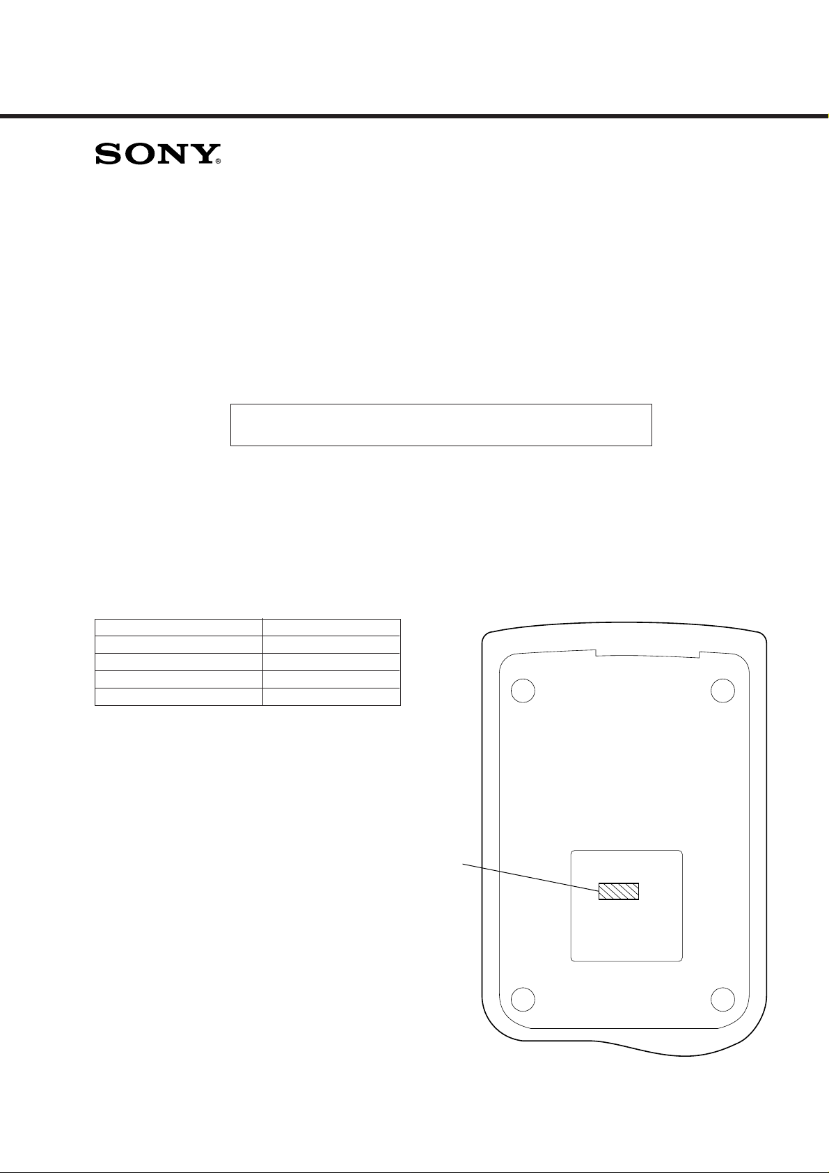
Refer to this service manual supplement-1, if the serial number given on the bottom of the base unit is as listed below.
If the given serial number does not correspond to the following table, refer to original service manual (9-925-742-11) .
Model Serial Number
SPP-ID300: US model 220,007 and later
SPP-ID300: Canadian model 113,004 and later
SPP-ID400: US model 254,010 and later
SPP-ID400: Canadian model 279,016 and later
Serial Number

TABLE OF CONTENTS
1. DISCRIMINATION .................................................... 1
2. TEST MODE
2-1. Base Unit......................................................................... 3
2-2. Handset............................................................................ 5
3. ELECTRICAL ADJUSTMENTS
Base Unit ......................................................................... 7
Handset ............................................................................ 10
4. DIAGRAMS
4-1. Note for Printed Wiring Boards and
Schematic Diagrams ....................................................... 13
4-2. Printed Wiring Board
– BASE UNIT Section (SPP-ID300) –........................... 15
4-3. Schematic Diagram
– BASE UNIT Section (SPP-ID300) –........................... 17
4-4. Printed Wiring Boards
– BASE UNIT Section (SPP-ID400) –........................... 19
4-5. Schematic Diagram
– BASE UNIT Section (SPP-ID400) –........................... 21
4-6. Printed Wiring Board
– HANDSET Section – ................................................... 23
4-7. Schematic Diagram
– HANDSET Section – ................................................... 25
5. EXPLODED VIEWS ................................................ 27
6. ELECTRICAL PARTS LIST ............................... 28
– 2 –
2. TEST MODE (SPP-ID300)
Note: See the original service manual for SPP-ID400.
2-1. BASE UNIT
[Setting the Test Mode]
1. Power on with press the [PAGE] key for two seconds.
2. CHARGE LED turns on for one second, and the Test Mode is set.
* Press the [PAGE] key for two seconds in test mode, EEPROM (IC102) is been initialize and CHARGE LED turns on.
After this operation, it isn’t able to change Test Mode No. and to change channel.
[Releasing the Test Mode]
To release the Test Mode, perform as follows:
• Turn off the power (disconnect and reconnect the AC adapter plug).
• Set the handset to charge on the base unit (except Test Mode 9).
• Bell in (except Test Mode 8).
[Changing the Test Mode Step]
1. Set the [DIALMODE] switch to the [P] (PULSE) position.
2. Press the [PAGE] key.
3. A step is changed each time the key is pressed, and CHARGE LED turns on for 300 msec.
[Changing the Channel]
1. Set the [DIALMODE] switch to the [T] (TONE) position.
2. Press the [PAGE] key.
3. A channel is changed each time the key is pressed, and CHARGE LED turns on for 300 msec.
* Channel will be back to initial channel (6 CH), when Test Mode No. is changed.
When it is Test Mode 12 or 13, DTMF will be changed.
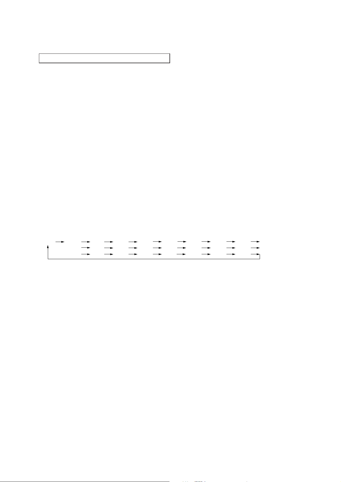
• Channel Rotation
6 CH
18 CH
5 CH
16 CH
1 CH
7 CH
17 CH
10 CH
8 CH
19 CH
11 CH
9 CH
20 CH
25 CH
12 CH
21 CH
2 CH
13 CH
22 CH
3 CH
14 CH
23 CH
4 CH
15 CH
24 CH
– 3 –

[Test Mode Execution]
Press the [PAGE] key to execute any of the following tests:
PLL IC
control
(IC1)
Step
1 VCO/TX FREQ. ADJ H H H L L
2 TX MODE CHECK L H H L H
3 TX DATA 1 H H H L L *1
4 RX ADJ H L L H H
5 DUPLEX L L H L H
6 DATA IN CHECK L L H L L *2
7 RSSI CHECK L L H L H *3
8 BELL CHECK H H L H L *4
9 CHARGE CHECK H H L H L *5
10 DTMF SINGLE TONE H H L H H *6
11 DTMF DUAL TONE H H L H H *7
12 TX DATA 2 H H H L L *8
Test Mode
Name
RX MUTE (EO pin @º)
TX MUTE (PDT pin 1)
Hard control
(IC2)
TXBENB (pin $º)
TXBPWR (pin $¡)
* Initial Channel of each step: 6 CH
Remarks
RLCONT (pin #¡)
*1. Test Mode 3: Continue output TX data as “ 0000……” (200 Hz).
*2. Test Mode 6: When locked receiving data is “ 0000……” or “ 1111……”, CHARGE LED turns on. (200, 400 Hz)
*3. Test Mode 7: When RSSI (IC2 pin #¢) is “ L” during 100 msec, CHARGE LED turns on.
*4. Test Mode 8: When it detects bell, CHARGE LED turns on.
*5. Test Mode 9: When CHRGIN (IC2 pin @£) is “ L” (charge on), CHARGE LED turns on.
*6. Test Mode 10: Set the [DIALMODE] switch to the [T] (TONE) position, and press the [PAGE] key.
DTMF will be changed.
ROW 1 → 2 → 3 → 4 → COL1 → COL2 → COL3 → COL4 → ROW1 → …… .
*DTMF frequency
ROW 1: 697 Hz COL1: 1209
ROW 2: 770 Hz COL2: 1336
ROW 3: 852 Hz COL3: 1477
ROW 4: 941 Hz COL4: 1633
*7. Test Mode 11: Set the [DIALMODE] switch to the [T] (TONE) position, and press the [PAGE] key.
DTMF will be changed.
1 → 2 → 3 → 4 → 5 → 6 → 7 → 8 → 9 → 0 →→ # → A → B → C → D →
*
1 → …… .
*8. Test Mode 12: Continue output TX data as “ 1111……” (400 Hz).
– 4 –

2-2. HANDSET
[Setting the Test Mode]
Power on with press the [*] key and the [#] key simultaneously for one second, and the Test Mode is set.
* Press the [SPEEDDIAL] key in Test Mode, EEPROM (IC501) is been initialize, and it beeps confirm tone.
* LIQUID CRYSTAL DISPLAY turns on/off, when press the [#] key.
[Releasing the Test Mode]
To release the Test Mode, perform as follows:
• Press the [TALK] key or [REDIAL/PAUSE] key.
• Turn off the power (disconnect and reconnect Battery connector).
• Set the handset to charge on the base unit (except Test Mode 10).
[Changing the Test Mode Step]
Press the each key of the Test Mode No.
[Changing the Channel]
Press the [CHANNEL] key.
* The channel is back to initial channel (6 CH), when Test Mode step is changed.
• Channel Rotation
6 CH
18 CH
5 CH
16 CH
1 CH
7 CH
17 CH
10 CH
8 CH
19 CH
11 CH
9 CH
20 CH
25 CH
12 CH
21 CH
2 CH
13 CH
22 CH
3 CH
14 CH
23 CH
4 CH
15 CH
24 CH
– 5 –

[Test Mode Execution]
Press the each key for the desired Test Mode step to execute any of the following tests:
PLL IC
control
(IC504)
Step
1 VCO/TX FREQ. ADJ 1 1 1 1 1 0 1 L IN L
2 TX MODE CHECK 2 1 0 1 1 0 1 L IN L
3TX DATA 3111101LINL*1
4 RX ADJ 4 0 1 0 1 0 1 L IN L
5 RX CHECK 5 0 1 0 1 0 1 H L L
6 BELL HIGH 6 1 1 1 1 0 1 L IN L
7 BELL LOW 7 1 1 1 1 0 1 L IN L
8 DUPLEX 8 0 0 0 1 0 1 L IN L
9 BAT. LOW CHECK 9 1 1 1 1 0 1 H L L *2
10 CHARGE CHECK 0 1 1 1 1 0 1 H L L *3
11 DATA IN CHECK 0 1 0 1 0 1 L IN L *4
12 STOP
13 RSSI CHECK PGM 0 1 0 1 0 1 L IN L *6
Test Mode
Name
KEY
REDIAL/
PAUSE
ALC DIS
LIM DIS
SP MUTE (SAO2 pin !¶)
TX MUTE (PDT pin 1)
RX MUTE (EO pin @º)
1 1 1 1 0 1 IN IN IN *5
CLK DIS
Hard control
(IC503)
TXBPWR (pin #ª)
TXVCO (pin $¡)
PXBPWR (pin %º)
* Initial Channel of each step: 6 CH
Remarks
*1. Test Mode 3: Continue output TX data as “ 0000……” or “ 1111……”. (200, 400 Hz)
To change TX data by press the [FLASH] key. (Initial data: “ 0000……” )
*2. Test Mode 9: When BATLOW (IC503 pin $∞) is “ L” (battery low), it beeps confirm tone.
*3. Test Mode 10: When CHARGE (IC503 pin !¢) is “ H” (Charge on), it beeps confirm tone.
*4. Test Mode 11: When locked receiving data is “ 0000……” or“ 1111……”, it beeps confirm tone. (200, 400 Hz)
*5. Test Mode 12: CPU clock keeps stopping.
*6. Test Mode 13: When RSSI (IC503 pin $™) is “ L ” during 100 msec, it beeps confirm tone.
– 6 –
3. ELECTRICAL ADJUSTMENTS
k
+
–
deviation meter
TP (ANT)
TP (GND)
+
–
deviation meter
TP (ANT)
TP (GND)
0 dBm = 0.775 V
BASE UNIT
• Make the set in test mode. (See page 3)
– TX Adjustment and Check –
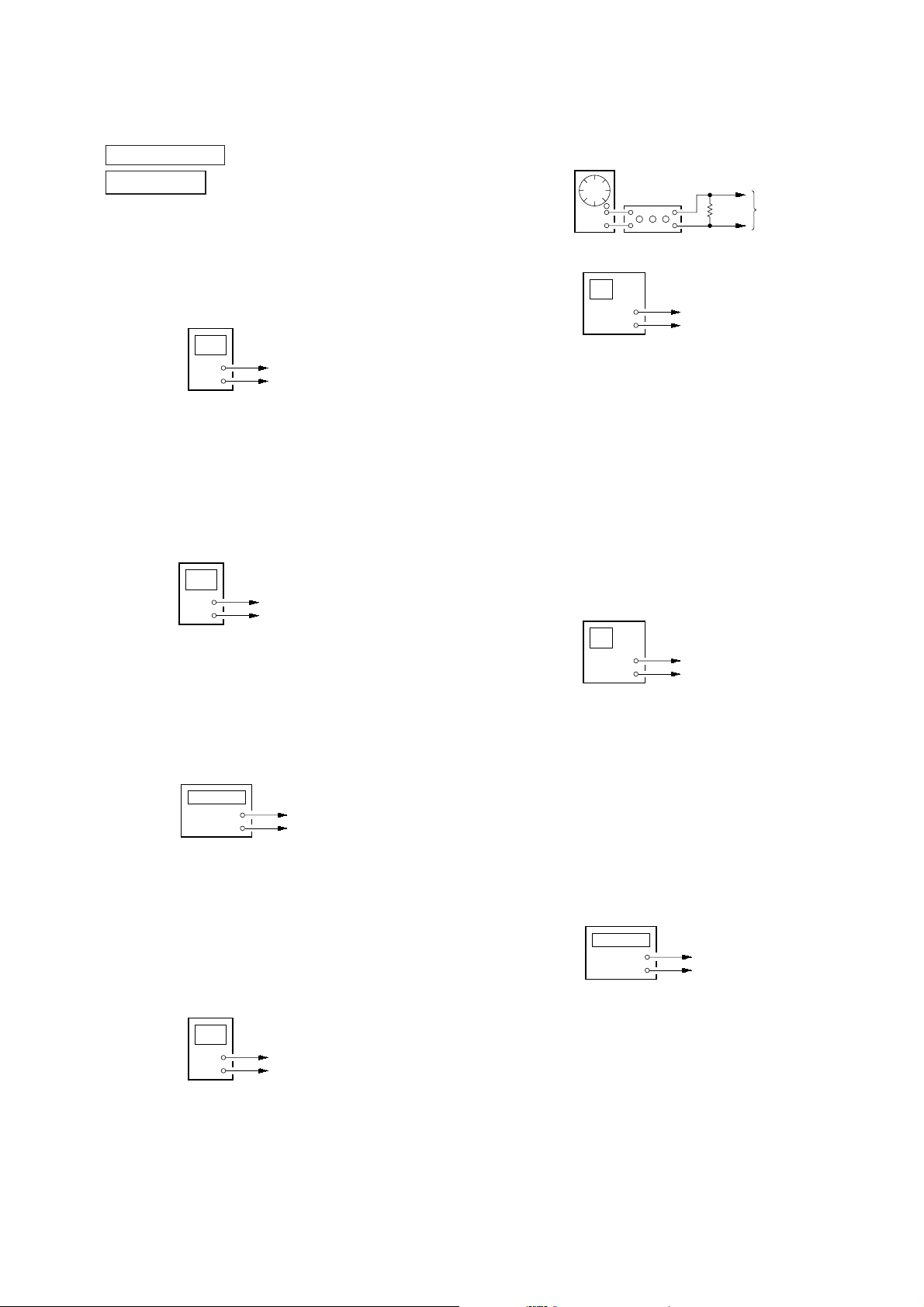
1. TX VCO Adjustment
Setting:
digital voltmeter
5. Modulation Sensitivity Check
Setting:
AF OSC
ATT
+
+
–
–
600
+
–
Ω
LINE jac
(J1)
1 kHz, –20 dBm
+
–
TP (TX VCO)
TP (GND)
Procedure:
1. Connect a digital voltmeter to TP (TX VCO) and TP (GND).
2. Adjust L10 so that the value of digital voltmeter becomes 2.7
±0.05 V (SPP-ID300) or 2.8 ±0.05 V (SPP-ID400) .
2. Power Check
Setting:
power meter
+
–
TP (ANT)
TP (GND)
Procedure:
1. Connect a power meter to TP (ANT) and TP (GND).
2. Check that the value of power meter is 7.5 ±3 dBm.
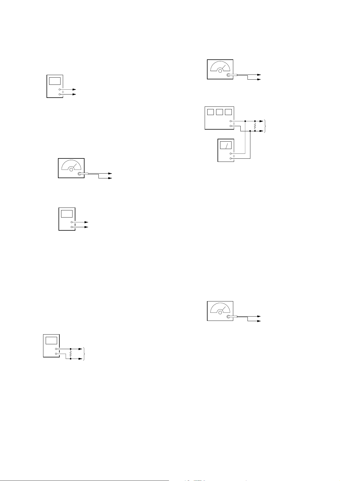
3. Frequency Check
Setting:
frequency counter
+
–
TP (ANT)
TP (GND)
Procedure:
1. Connect an AF OSC to the LINE jack (J1).
2. Connect a deviation meter to TP (ANT) and TP (GND).
3. Set the [DIALMODE] switch (S1) to the [P] (PULSE) position
(SPP-ID300) .
4. Press the [PAGE] key (S4) to change the test mode step to TX
MODE CHECK. (SPP-ID300)
Press the [SPEAKERPHONE] key (S2) to change the test mode
step to TX MODE CT PASS. (SPP-ID400)
5. Check that the value of deviation meter is ±2.25 kHz to ±3.95
kHz.
6. Data Deviation Check
Setting:
Procedure:
1. Press the [PAGE] key (S4) to change the test mode step to TX
DATA1. (SPP-ID300)
Press the [SPEAKERPHONE] key (S2) twice to change the test
mode step to TX DATA. (SPP-ID400)
2. Check that the value of deviation meter is ±3.75 kHz to ±6.75
kHz.
Procedure:
1. Connect a frequency counter to TP (ANT) and TP (GND).
2. Check that the value of frequency counter is 46.77 MHz ±1.2
kHz.
4. RX VCO Adjustment
Setting:
digital voltmeter
+
–
TP (RX VCO)
TP (GND)
Procedure:
1. Connect a digital voltmeter to TP (RX VCO) and TP (GND).
2. Adjust L7 so that the value of digital voltmeter becomes 1.3
±0.05 V .
7. Channel Change Check
Setting:
frequency counter
+
–
TP (ANT)
TP (GND)
Procedure:
1. Connect a frequency counter to TP (ANT) and TP (GND).
2. Set the [DIALMODE] switch (S1) to the [T] (TONE) position.
(SPP-ID300)
3. When press the [PAGE] key (S4) (SPP-ID300) or the
[INTERCOM] key (S3) (SPP-ID400) , check that the frequency
of frequency counter (channel) is changed each time the key is
pressed, and CHARGE LED lights up for 300 msec.
– 7 –
– RX Adjustment and Check –
)
k
k
1. RX VCO Voltage Check
Setting:
digital voltmeter
+
–
TP (RX VCO)
TP (GND)
4. Sensitivity Adjustment
Setting:
SSG
Carrier frequency: 48.76 MHz
Modulation: 1 kHz,
Output level: 20 dBµ EMF
SINAD meter
±
3 kHz deviation
TP (ANT)
TP (GND)
Procedure:
1. Connect a digital voltmeter to TP (RX VCO) and TP (GND).
2. Check that the value of digital voltmeter is 1.3 ±0.1 V
2. DISCRI Coil Adjustment
Setting:
SSG
TP (ANT)
Carrier frequency: 49.83 MHz
Modulation: 1 kHz,
Output level: 66 dBµ EMF
noise meter
±
3 kHz deviation
+
–
TP (DISC
TP (GND)
TP (GND)
Procedure:
1. Connect a SSG to TP (ANT) and TP (GND) .
2. Connect a noise meter to TP (DISC) and TP (GND) .
3. Set the [DIALMODE] switch (S1) to the [P] (PULSE) position.
(SPP-ID300)
4. Press the [PAGE] key (S4) three times to change the test mode
step to RX ADJ. (SPP-ID300)
Press the [SPEAKERPHONE] key (S2) four times to change the
test mode step to RX ADJ TXB ON. (SPP-ID400)
5. Adjust L3 so that the value of noise meter becomes maxim um.
600
+
–
level meter
+
–
Ω
LINE jac
(J1)
Procedure:
1. Connect a SIN AD meter and le vel meter to the LINE jac k (J1).
2. Change the output level of SSG to 20 dBµ EMF.
3. Change the carrier frequency of SSG to 48.76 MHz.
4. Set the [DIALMODE] switch (S1) to the [T] (TONE) position
(SPP-ID300) .
5. Press the [PAGE] key (S4) (SPP-ID300) or the [INTERCOM] key
(S3) (SPP-ID400) four times to change the channel to 11CH.
6. Adjust L6 to get maximum reading on the SINAD meter.
7. Check that the value of level meter is more than 12 dB.
8. Change the output level of SSG to 5 dBµ EMF.
9. Adjust L6 to get maximum reading on the SINAD meter.
10. Check that the value of level meter is more than 12 dB.
11. Change the frequency of SSG to 49.5 MHz.
12. Press the [PAGE] key (S4) (SPP-ID300) or the [INTERCOM] key
(S3) (SPP-ID400) to change the channel to 25CH.
13. Check that the value of level meter is more than 12 dB.
5. RSSI ON/OFF Level Check
Setting:
SSG
3. TEL Out Level Adjustment
Setting:
noise meter
600
+
–
Ω
LINE jac
(J1)
Procedure:
1. Connect a noise meter to the LINE jack (J1) .
2. Adjust RT2 so that the value of noise meter becomes –3.5 ±0.5
dBm.
TP (ANT)
Carrier frequency: 49.83 MHz
Modulation: off,
Output level: 15 dBµ EMF
±
0 kHz deviation
TP (GND)
Procedure:
1. Change the carrier frequency of SSG to 49.83 MHz.
2. Change the modulation of SSG to OFF (±0 kHz deviation).
3. Change the output level of SSG to 15 dBµ EMF.
4. Set the [DIALMODE] switch (S1) to the [P] (PULSE) position
(SPP-ID300) .
5. Press the [PAGE] key (S4) three times (SPP-ID300) or the
[SPEAKERPHONE] key (S2) twice (SPP-ID400) to change the
test mode step to RSSI CHECK.
6. Check that the CHARGE LED (D11) lights up.
7. Change the output level of SSG to 3 dBµ EMF.
8. Check that the CHARGE LED (D11) goes off.
– 8 –
6. Data In Check
Setting:
SSG
TP (ANT)
Carrier frequency: 49.83 MHz
Modulation: 200 Hz,
Output level: 3 dB
±
4 kHz deviation
µ
EFM
TP (GND)
Procedure:
1. Change the modulation of SSG to 200 Hz (±4 kHz deviation).
2. Set the [DIALMODE] switch (S1) to the [P] (PULSE) position
(SPP-ID300) .
3. Press the [PAGE] key (S4) eleven times (SPP-ID300) or the
[SPEAKERPHONE] key (S2) twice (SPP-ID400) to change the
test mode step to DATA IN CHECK.
4. Check that the CHARGE LED (D11) lights up or blinks.
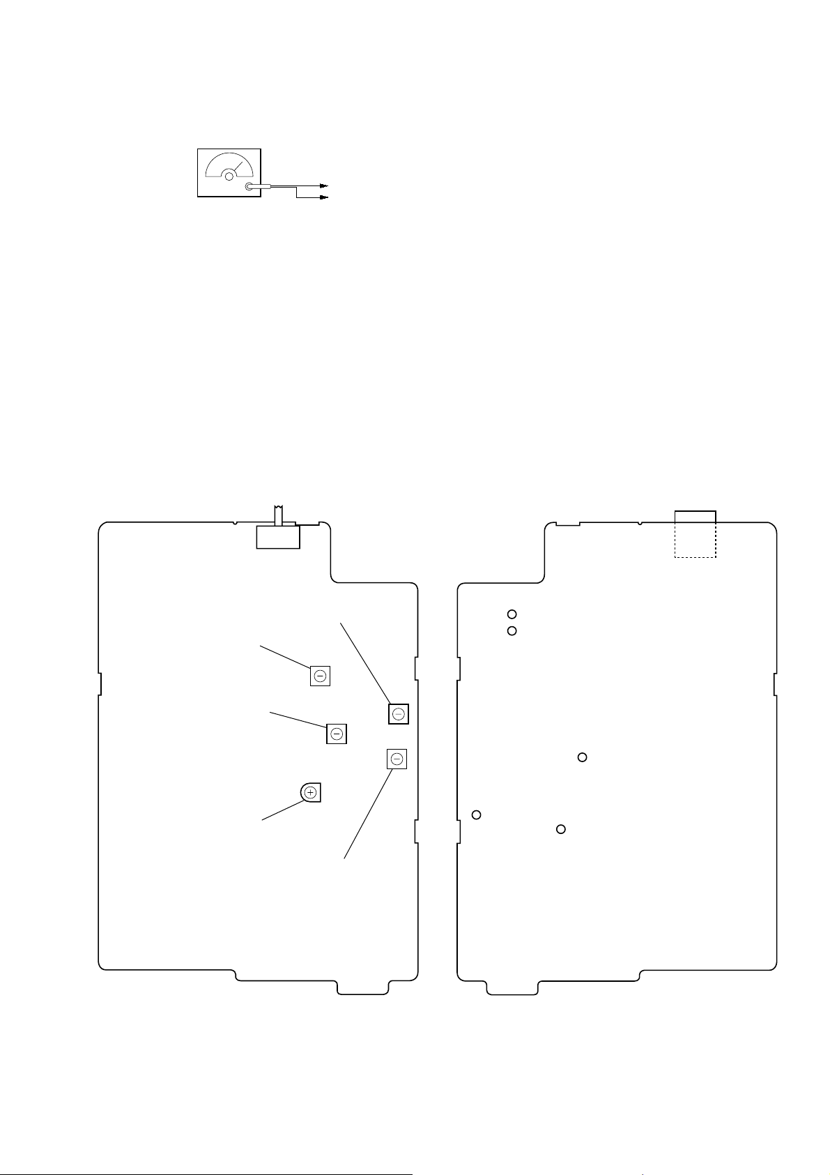
Adjustment Location:
– BASE (MAIN) BOARD (Component Side) – – BASE (MAIN) BOARD (Conductor Side) –
T (TONE) P (PULSE)
L6 Sensitivity Adjustment
L10 TX VCO Adjustment
L3 DISCRI Coil Adjustment
RT2 TEL Out Level Adjustment
L7 RX VCO Adjustment
˜
S1
J1
TP (GND)
TP (ANT)
TP (DISC)
TP (RX VCO)
TP (TX VCO)
– 9 –
 Loading...