

Sony SPP-AQ600 Service manual
SPP-AQ600
SERVICE
MANUAL
Canadian Model
SPECIFICATIONS
MICROFILM
CORDLESS TELEPHONE

TABLE OF CONTENTS
Specifications ........................................................................... 1
1. GENERAL
Location and Function of Controls .................................... 3
Read this first ..................................................................... 4
Step 1 : Checking the package contents............................. 4
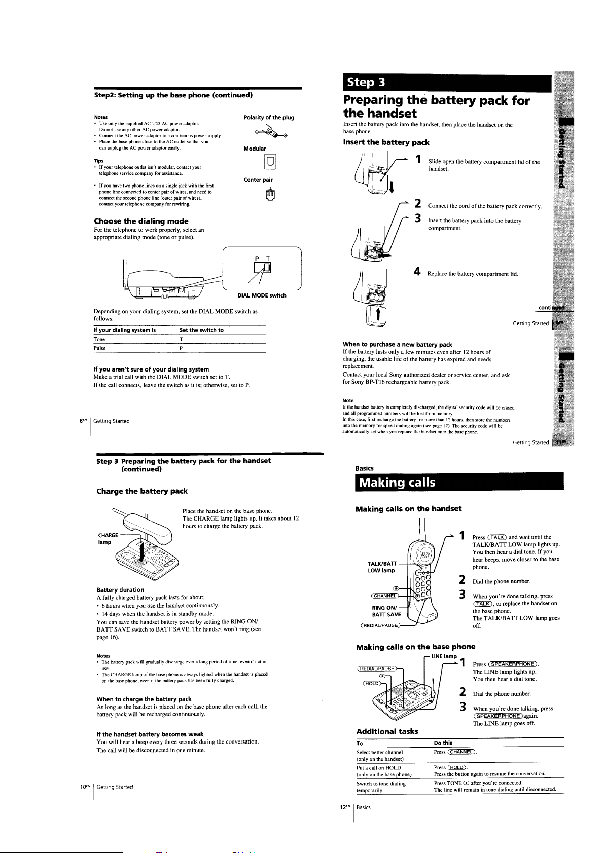
Step 2 : Setting up the base phone ..................................... 4
Step 3 : Preparing the battery pack for the handset ........... 5
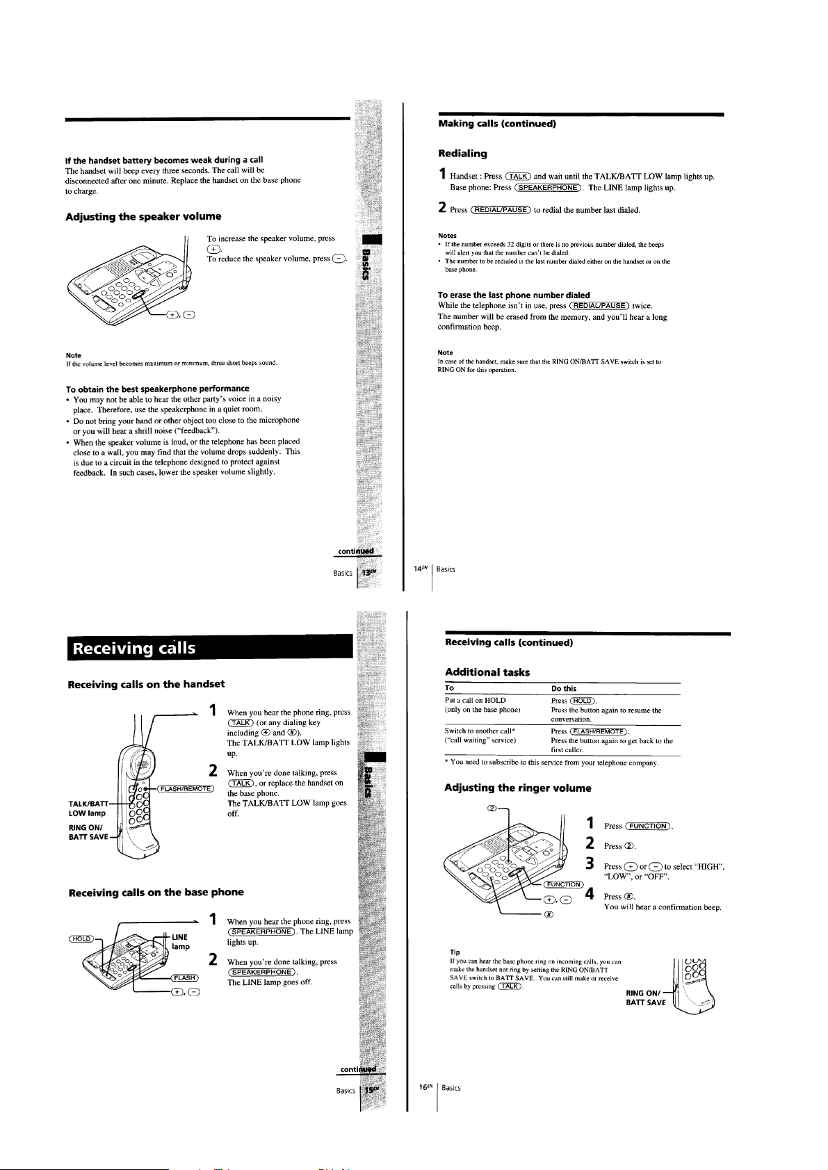
Making calls....................................................................... 5
Receiving calls ................................................................... 6
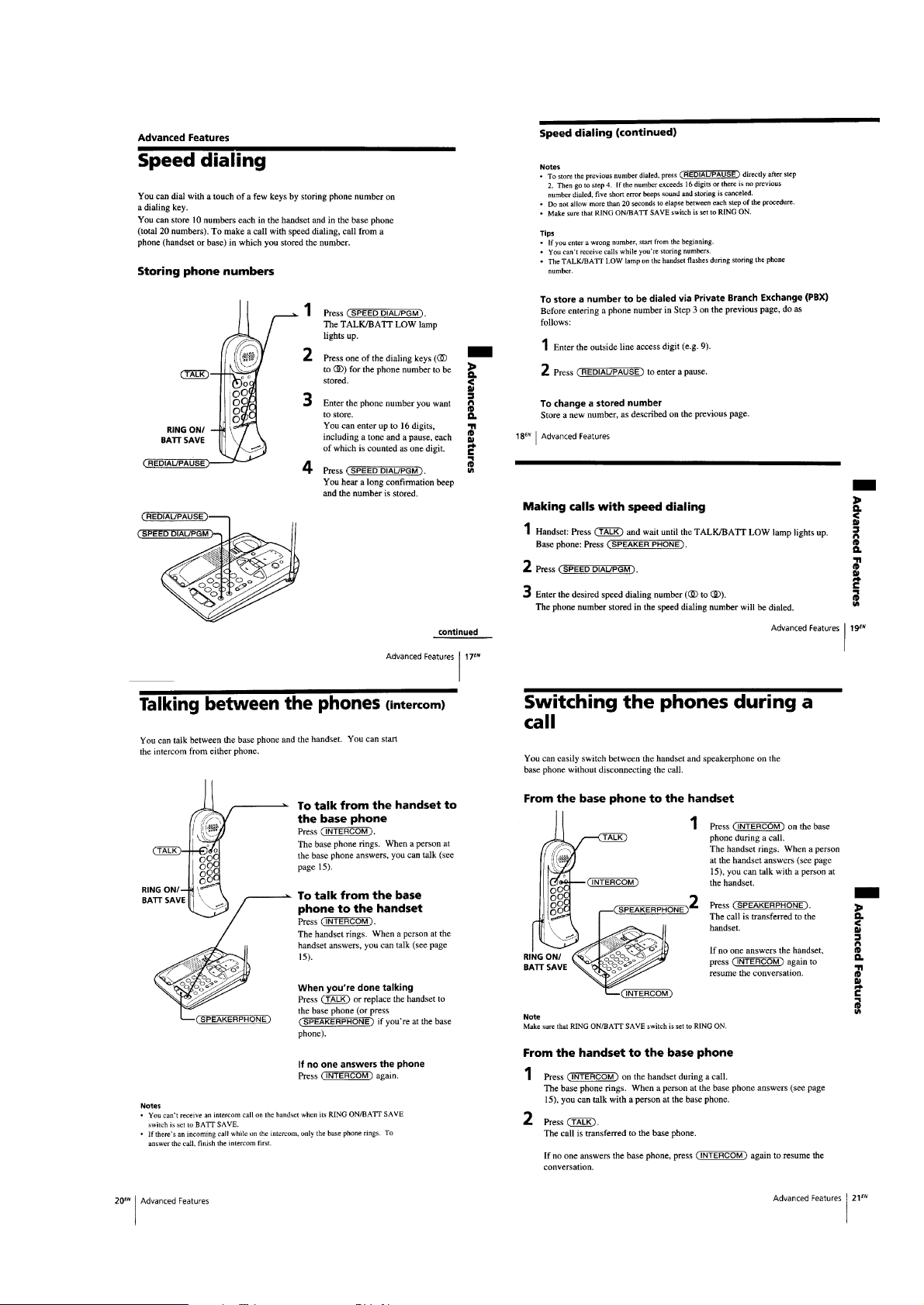
Speed dialing...................................................................... 7
Talking between the phones (Intercom) ............................. 7
Switching the phones during a call .................................... 7
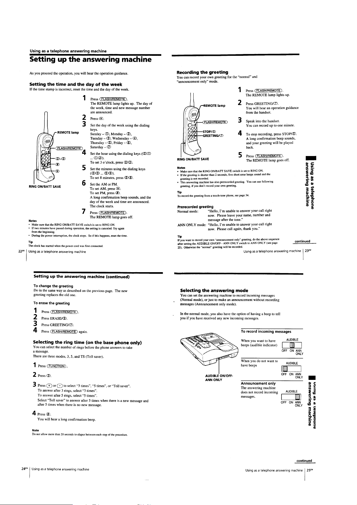
Setting up the answering machine ..................................... 8
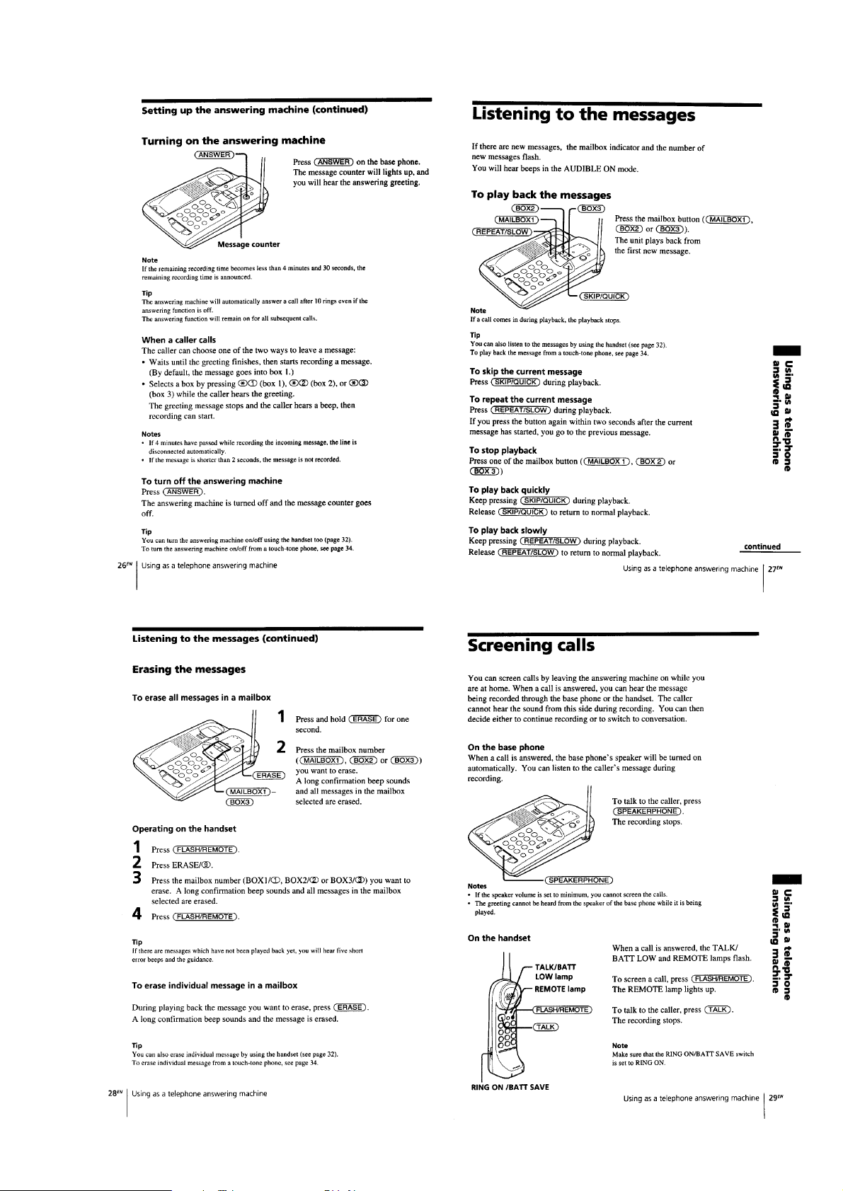
Listening to the messages .................................................. 9
Screening calls ................................................................... 9
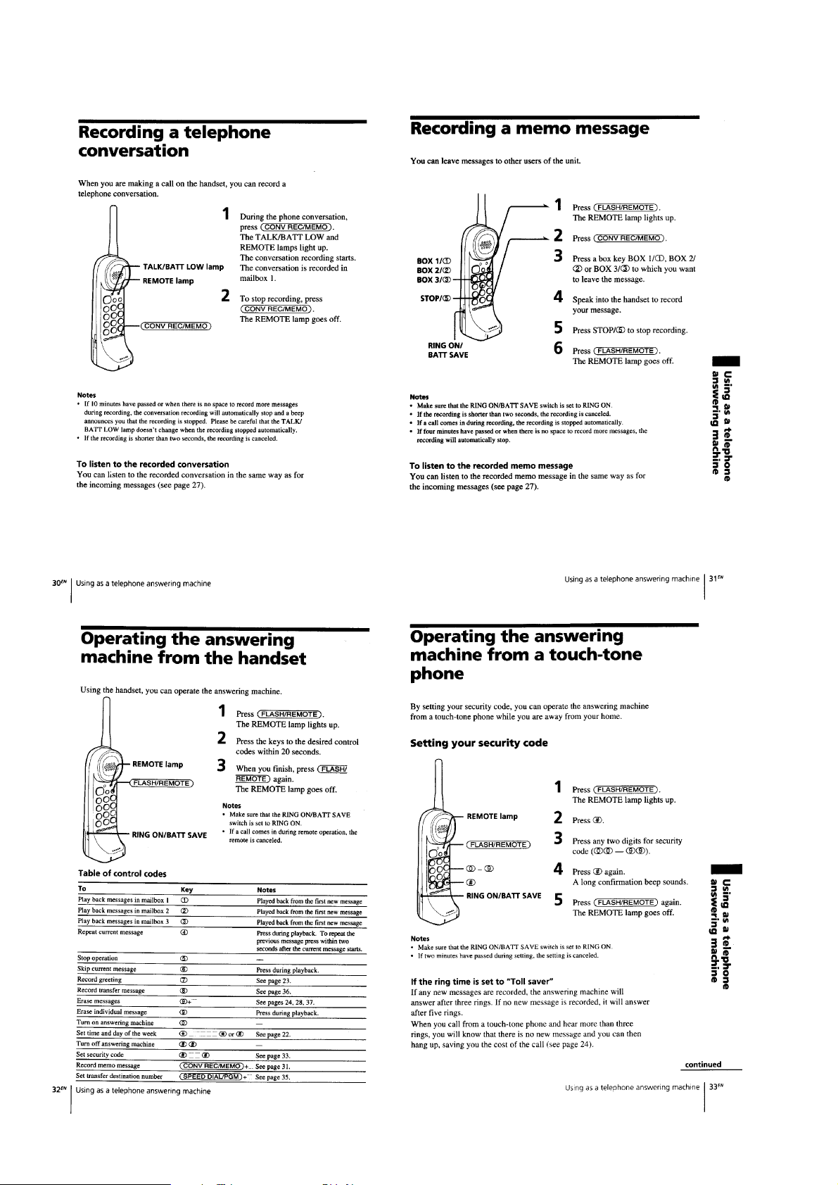
Recording a telephone conversation ................................ 10
Recording a memo message............................................. 10
Operating the answering machine from the handset........ 10
Operating the answering machine from
a touch-tone phone ........................................................... 10
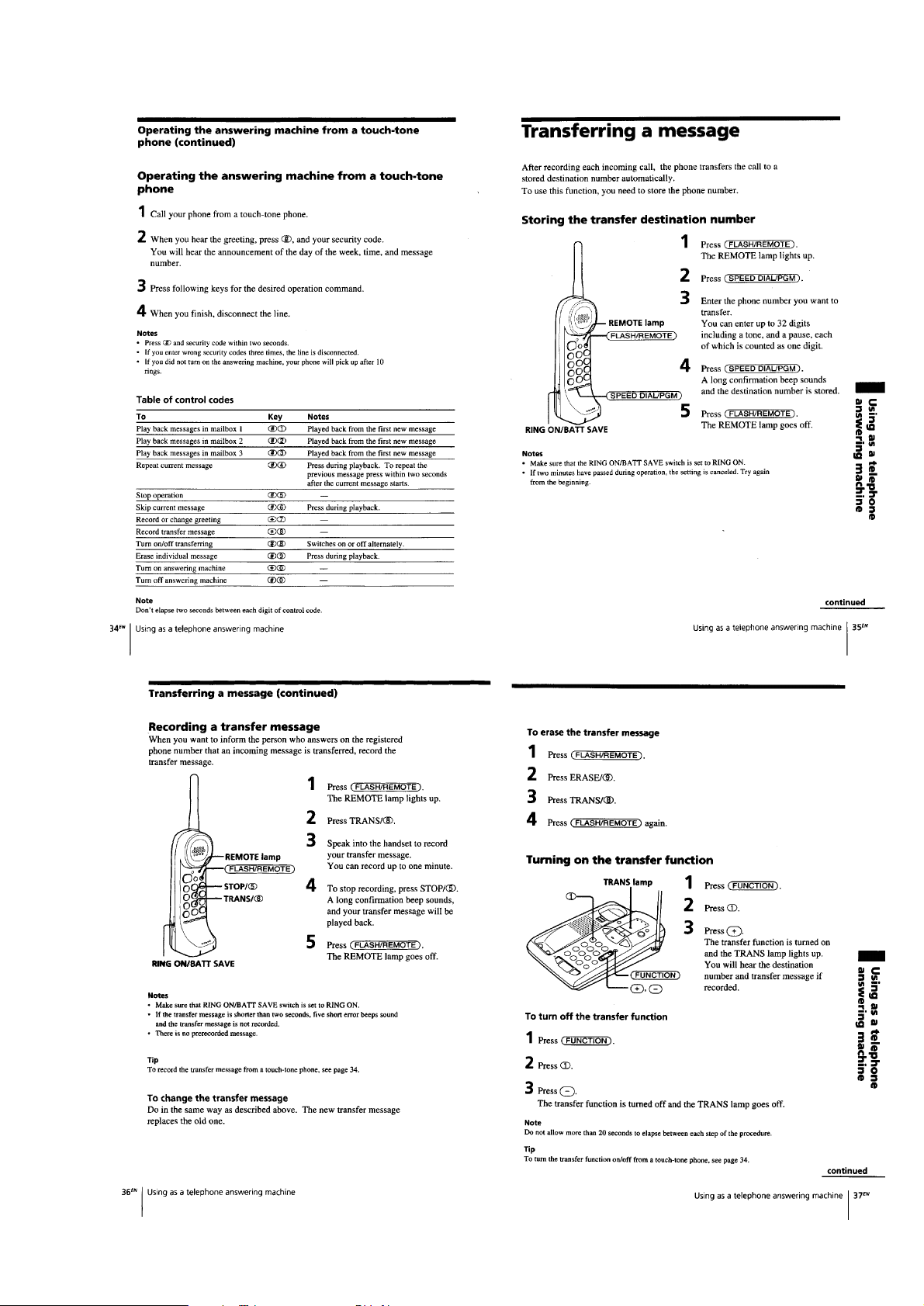
Transferring a message .....................................................11
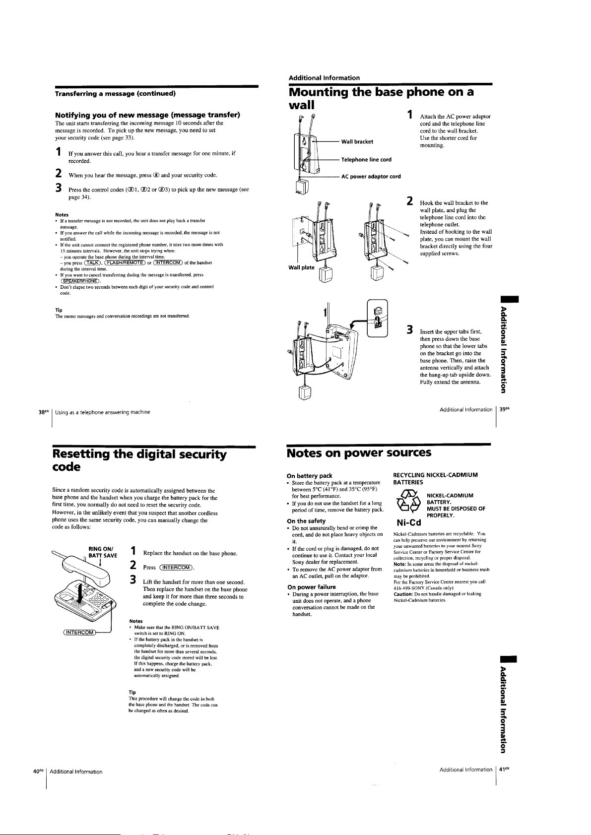
Mounting the base phone on a wall ................................. 12
Resetting the digital security code ................................... 12
Notes on power sources ................................................... 12
2. DISASSEMBLY ............................................................. 13
3. TEST MODE .................................................................. 14
4. ADJUSTMENTS
4-1. Base Unit Section ..................................................... 19
4-2. Handset section......................................................... 22
5. CONNECTION PROT OCOL ....................................... 24
6. DIAGRAMS
6-1. Explanation of IC Terminals..................................... 26
6-2. Block Diagram (Base Unit Section) ......................... 30
6-3. Block Diagram (Handset Section) ............................ 33
6-4. Printed Wiring Boards (Handset Section) ................ 36
6-5. Schematic Diagram (Handset Section)..................... 39
6-6. Printed Wiring Boards (Base Unit Section).............. 42
6-7. Schematic Diagram (Base Unit Section) .................. 45
6-8. Printed Wiring Boards (Base Key Section) .............. 49
6-9. Schematic Diagram (Base Key Section) .................. 51
7. EXPLODED VIEWS
7-1. Base Unit Section ..................................................... 53
7-2. Handset Section ........................................................ 54
8. ELECTRICAL PARTS LIST ........................................ 55
Flexible Circuit Board Repairing
• Keep the temperature of the soldering iron around 270°C during
repairing.
• Do not touch the soldering iron on the same conductor of the
circuit board (within 3 times).
• Be careful not to apply force on the conductor when soldering or
unsoldering.
Notes on chip component replacement
• Never reuse a disconnected chip component.
• Notice that the minus side of a tantalum capacitor may be damaged by heat.
SAFETY-RELATED COMPONENT WARNING!!
COMPONENTS IDENTIFIED BY MARK ! OR DOTTED LINE WITH
MARK !ON THE SCHEMATIC DIAGRAMS AND IN THE PARTS
LIST ARE CRITICAL TO SAFE OPERATION.
REPLACE THESE COMPONENTS WITH SONY PARTS WHOSE
PART NUMBERS APPEAR AS SHOWN IN THIS MANUAL OR IN
SUPPLEMENTS PUBLISHED BY SONY.
ATTENTION AU COMPOSANT AYANT RAPPORT
À LA SÉCURITÉ!
LES COMPOSANTS IDENTIFIÉS P AR UNE MARQUE ! SUR LES
DIAGRAMMES SCHÉMA TIQUES ET LA LISTE DES PIÈCES SONT
CRITIQUES POUR LA SÉCURITÉ DE FONCTIONNEMENT. NE
REMPLACER CES COMPOSANTS QUE PAR DES PIÈCES SONY
DONT LES NUMÉROS SONT DONNÉS DANS CE MANUEL OU
DANS LES SUPPLÉMENTS PUBLIÉS PAR SONY.
– 2 –
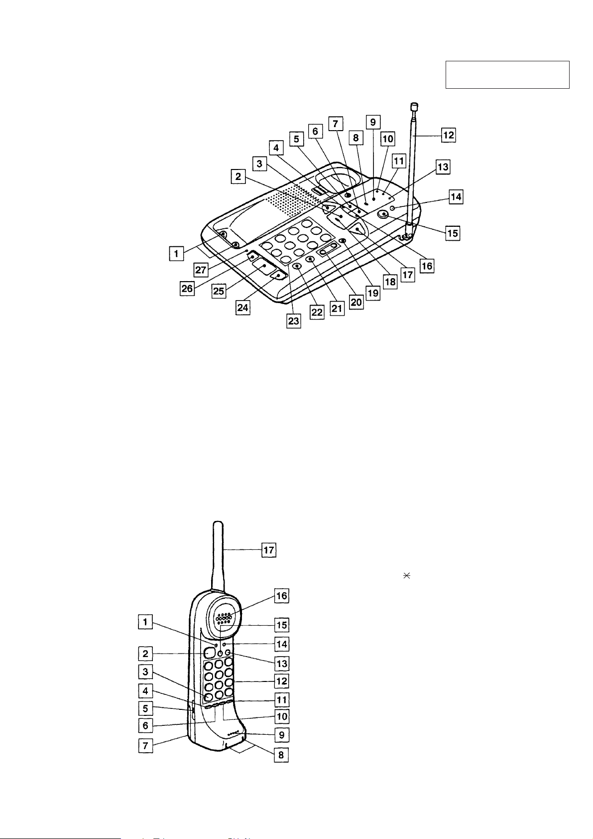
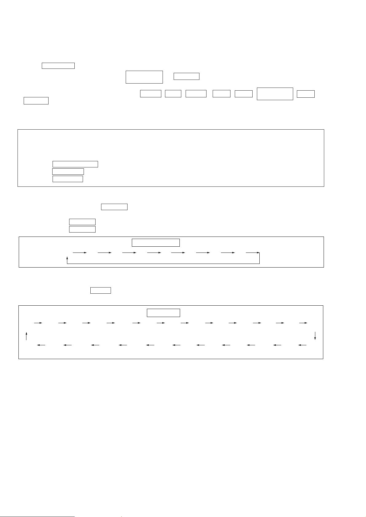
LOCATION AND FUNCTION OF CONTROLS
BASE UNIT
SECTION 1
GENERAL
This section is extracted from
instruction manual.
HANDSET
1 Charging ter minals
2 PLAY/STOP, MAILBOX1 button
3 REPEAT/SLOW buttons
4 BOX2 lamp
5 BOX2 button
6 FLASH button
7 BOX3 button
8 TRAS lamp
9 Display (LED)
!º POWER lamp
!¡ LINE lamp
!™ Antenna
!£ CHARGE lamp
!¢ ERASE button
!∞ ANSWER button
!§ BOX3 lamp
!¶ SKIP/QUICK button
!• MAILBOX1 lamp
!ª FUNCTION button
@º VOL buttons
+ button
– button
@¡ REDIAL/PAUSE button
@™ SPEED DIAL/PGM (program)
@£ Dialing keys
@¢ INTERCOM button
@∞ SPEAKERPHONE button
@§ HOLD button
@¶ HOLD lamp
1 TALK/BATT LOW lamp
2 TALK button
3 TONE ( ) button
4 CHANNEL button
5 RING ON/BATT SAVE switch
6 SPEED DIAL/PGM (program) button
7 Batter y compartment
8 Charging terminals
9 Microphone
!º REDIAL/PAUSE button
!¡ CONV REC/MEMO button
!™ Dialing keys
!£ FLASH/REMOTE button
!¢ REMOTE lamp
!∞ INTERCOM button
!§ Speaker
!¶ Antenna
– 3 –
– 4 –
– 5 –
– 6 –
– 7 –
– 8 –
– 9 –
– 10 –
– 11 –
– 12 –
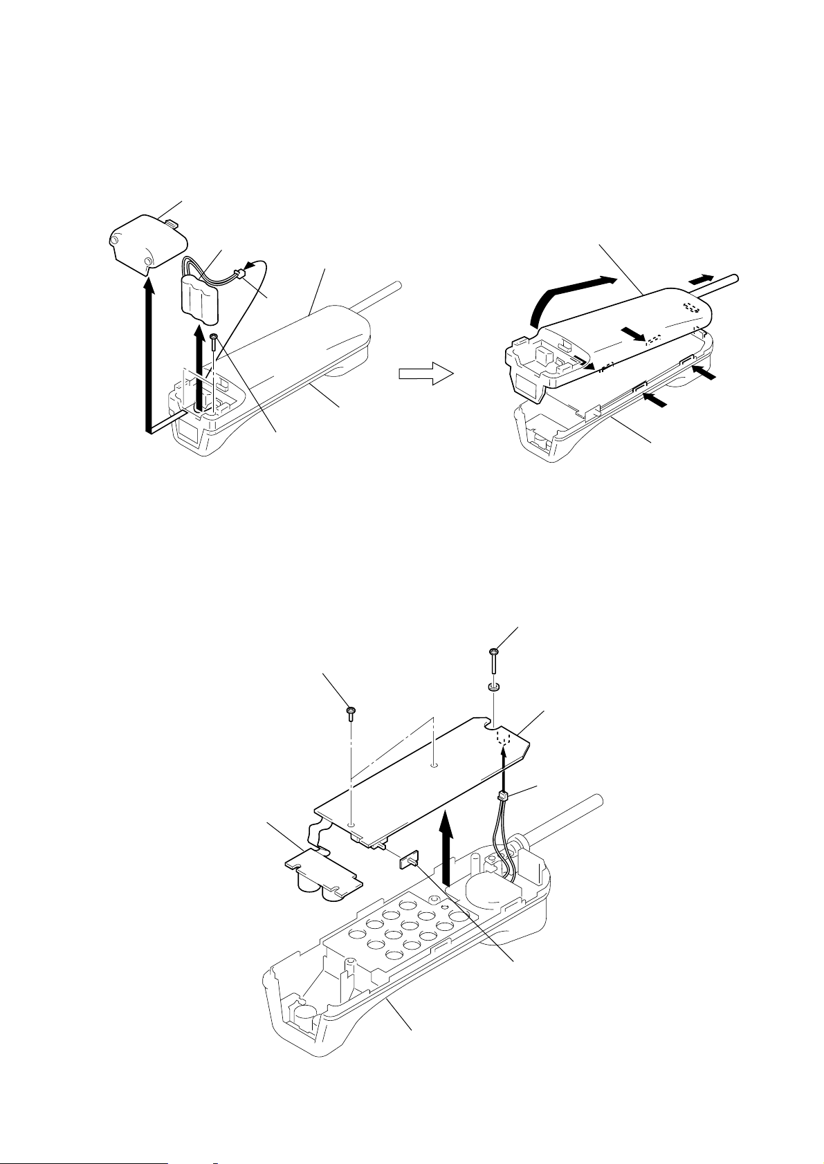
SECTION 2
1
1
2
1
1
2
Cabinet (rear), hand
Cabinet (front), hand
)
DISASSEMBLY
Note : Follow the disassembly procedure in the numerical order given.
[BATTERY]
1
Lid, Battery case
Battery (BT901)
3
2
J502
4
(+BTP 2.6x12)
Cabinet (rear), hand
Screws
[CABINET (REAR), HAND]
Cabinet (front), hand
[HAND MAIN BOARD, HAND MICROPHONEN BOARD]
1
Screws (+BTP 2.6x8)
Hand microphone board
4
2
Screw (+BTP 2.6x16
Hand main board
3
J501
5
Knob (slide)
Cabinet (front), hand
– 13 –
SECTION 3
TEST MODE
BASE UNIT
RF TEST MODE
<How to Set the Test Mode>
1. Set the DIAL MODE switch to P (plus) side.
2. Reset power ON while holding down both the
When the test mode is set, a beep will sound and the POWER , LINE , TRANS , BOX 2 , BOX 3 ,
CHARGE LEDs will light. Test Mode 1 will thereby be set.
<How to Release the Test Mode>
Cancel the test mode by executing any of the following :
r
Turn OFF the POWER (disconnect and reconnect the AC adapter plug).
r
Set the handset to the CHARGE mode on the base unit (charge ON).
r
Code receiving
r
BELL IN
r
Press the SPEAKERPHONE key
r
Press the INTERCOM key
r
Press the FUNCTION key
<Changing the Test Mode>
Change the test mode by pressing the ANSWER key once.
Displays the test mode step on the 7 segment LED. (Initial display is “1’’.)
Example : Press the ANSWER key once to set test mode No. 2
Press the ANSWER key three times to set test mode No. 4
PLAY/STOP
(MAILBOX 1)
and ANSWER ke ys, and DSP test mode will be set after about 1 second.
(Check tone is heard.)
PLAY/STOP
(MAILBOX 1)
, HOLD and
Test Mode Rotation
1 2 3 4 5 6 7 8
<Changing the Channel>
To change the channel, press the ERASE key. The channel will change in the following sequence.
Channel is shown on the 7 segment LED for 1 second
CH Rotation
6CH
(6)
24CH
(E)
18CH
(18)
23CH
(d)
1CH
(1)
22CH
(c)
10CH
(10)
21CH
(b)
11CH
(11)
20CH
(a)
25CH
(F)
19CH
(19)
2CH
(2)
17CH
(17)
3CH
(3)
16CH
(16)
4CH
(4)
15CH
* The character in the ( ) is the letter shown for 1 second on the 7 segment LED.
* When the STEP is changed. the CHANNEL will be reset to the initial channel.
(15)
5CH
(5)
7CH
(7)
14CH
(14)
8CH
(8)
13CH
(13)
9CH
(9)
12CH
(12)
– 14 –
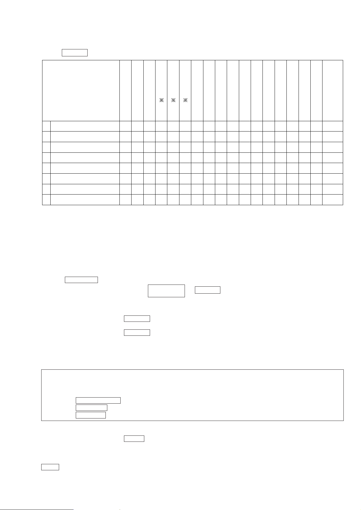
<Test Mode Execution>
Press the ANSWER key to execute the tests below.
I
T
T
T
R
N
X
X
W
X
B
M
P
U
T
R
E
I
B
T
I
E
A
N
L
B
X
M
U
S
P
M
U
T
T
E
E
C
M
M
S
P
P
P
P
P
P
R
C
P
I
C
U
T
E
M
A
A
A
A
A
A
S
S
S
S
S
S
U
T
1
E
S
2
3
S
S
S
4
5
L
S
S
C
O
6
N
T
C
H
H
G
G
O
C
F
N
F
T
H
1 6 L H ON ON ON H H L L L L L L L H LVCO/TX FRQ. ADJ
2 6 L H OFF ON ON H H L L L L L L H H LTX MODE CHECK
3 6 L H ON ON ON H H L L L L L L L H L * • 1
TX DATA
4 6 H L ON OFF OFF H H L L L L L L H H LRX TEL CHECK
5 6 L H OFF OFF OFF H H L L L L L L H H LRX CHECK
R
E
M
A
R
K
6 6 L H OFF OFF OFF H H L L L L L L L H LDATA IN CHECK
7 6 L H OFF ON OFF H H L L L L L L H H LRSSI CHECK
8 6 L H ON ON OFF H H L L L L L L L H H/LCHANNEL DATA CHECK
This is IF IC (MC13110FB) port.
* • 1 Test Mode 3 : Continuously outputs SEND data, “ 0000...” (at 200Hz).
* • 2 Test Mode 6 : Continuously inputs RECEIVE data and a loud bell tone sounds (at 200Hz).
* • 3 T est Mode 7 : A loud bell tone sounds when a carrier is present.
Carrier : L
No Carrier : H
* • 4 Test Mode 8 : Continuously outputs data, “ 0000...” to the charge terminal.
DSP Test Mode
<Setting the Test Mode>
1. Set the DIAL MODE switch to T (TONE) side.
2. Reset power ON while holding down both the
PLAY/STOP
(MAILBOX 1)
and ANSWER keys, and DSP test mode will be set after about 1 second.
<Changing the Test Mode>
Change the test mode by pressing the ANSWER key once.
Disabled during REC/PLAY test.
Change the test mode by pressing the ANSWER key once.
Displays the test mode step on the 7 segment LED. (Initial display is “1’’.)
* • 2
* • 3
* • 4
(Check tone is heard.)
<Canceling the Test Mode>
Cancel the test mode by executing any of the following :
r
Turn OFF the POWER (disconnect and reconnect the AC adapter plug).
r
Set the handset to the CHARGE mode on the base unit (charge ON).
r
Code receiving
r
BELL IN
r
Press the SPEAKERPHONE key
r
Press the INTERCOM key
r
Press the FUNCTION key
<Changing the Channel>
Change the test mode by pressing the ERASE key once.
Channel is displayed on the 7 segment LED for 1 second. (But channel returns to intial channel once the step is changed.)
<DTMF Out>
VOL + key
– 15 –
 Loading...