

Sony SPP-A985 Service manual
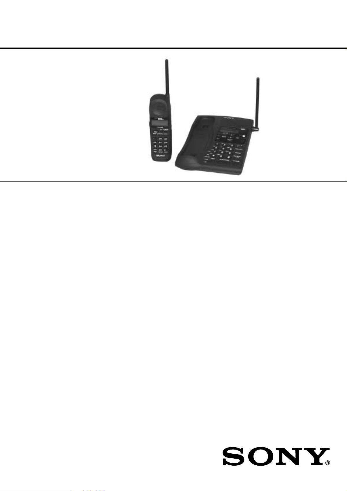
SPP-A985
SERVICE MANUAL
Ver 1.0 2000.12
SPECIFICATIONS
General
Frequency band
902 - 928 MHz
Operating channel
30 channels
Dial signal
Tone, 10 PPS (pulse) selectable
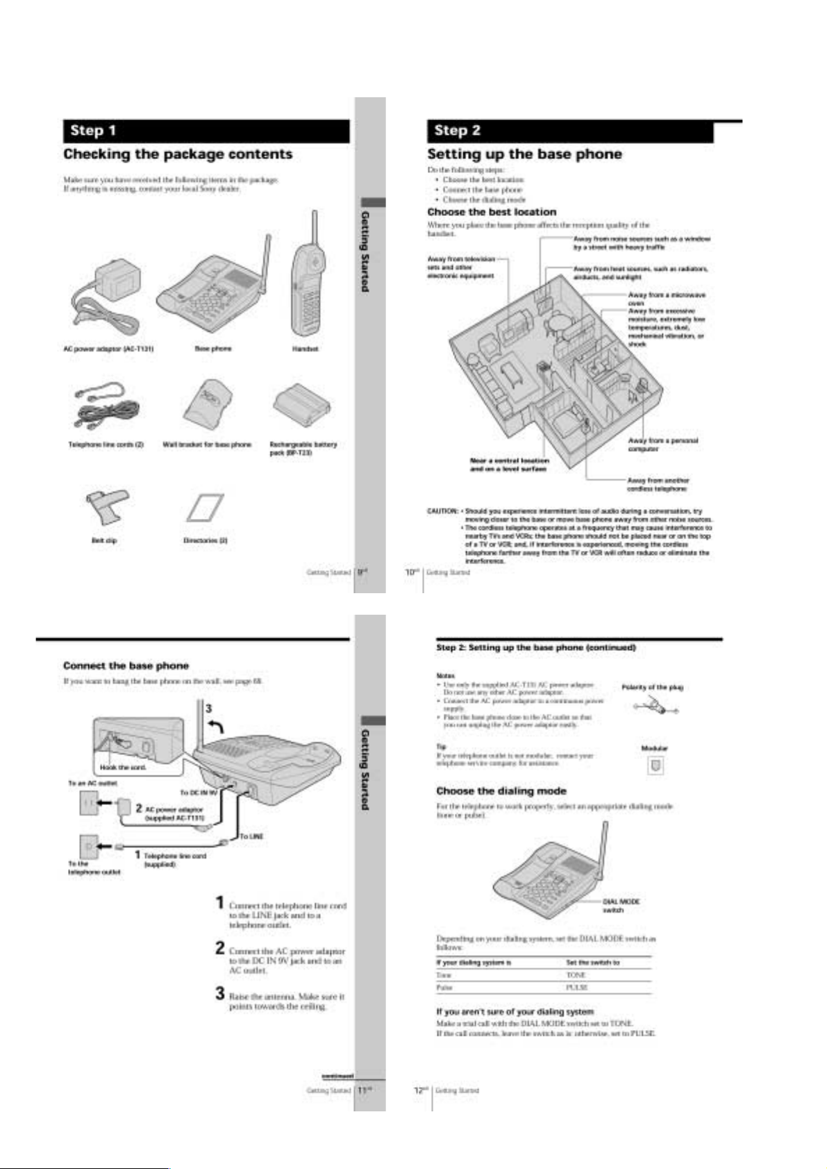
Supplied accessories
Telephone line cords (3)
Handset AC power adaptor (AC-T128)
Wall bracket for base unit
Base unit
Rechargeable battery pack (BP-T23)
Belt clip
US Model
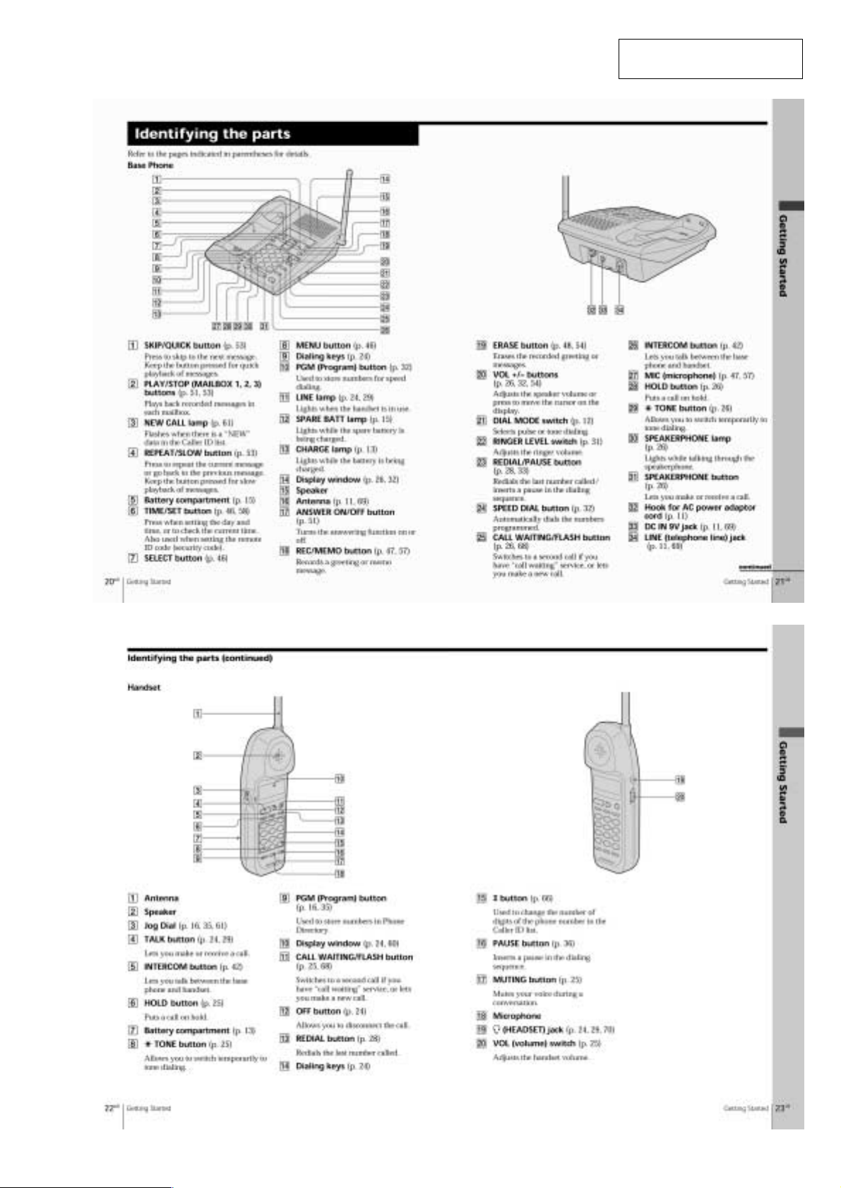
Base unit
Power source
DC 9V from AC power adaptor
AC-T131
Battery charging time
Approx. 24 hours
Dimensions
Approx. 7 3⁄8 x 2 3⁄4 x 9 1⁄8 inches (w/h/d), antenna excluded
(approx. 186 x 68 x 229 mm)
Antenna: Approx. 4 3⁄4 inches
(approx. 120 mm)
Mass
Approx. 1 lb 8 oz
(approx. 664 g), wall bracket excluded
Handset
Power source
Rechargeable battery pack BP-T23
Battery charging time
Approx. 12 hours
Battery life
Standby: Approx. 7 days
Talk: Approx. 7 hours
Dimensions
Approx. 2 3⁄8 x 7 1⁄2 x 1 13⁄16 inches (w/h/d), antenna excluded
(approx. 58 x 177 x 46 mm)
Antenna: Approx. 2 7⁄8 inches
(approx. 72 mm)
Mass
Approx. 9.5 oz
(approx. 270 g), battery included
Answering machine
Maximum recording time
About 15 minutes, using incorporated IC
Greeting message
Up to 90 seconds per each
Incoming and Memo message
Up to 4 minutes per message
Design and specifications are subject to change without notice.
2-LINE CORDLESS TELEPHONE
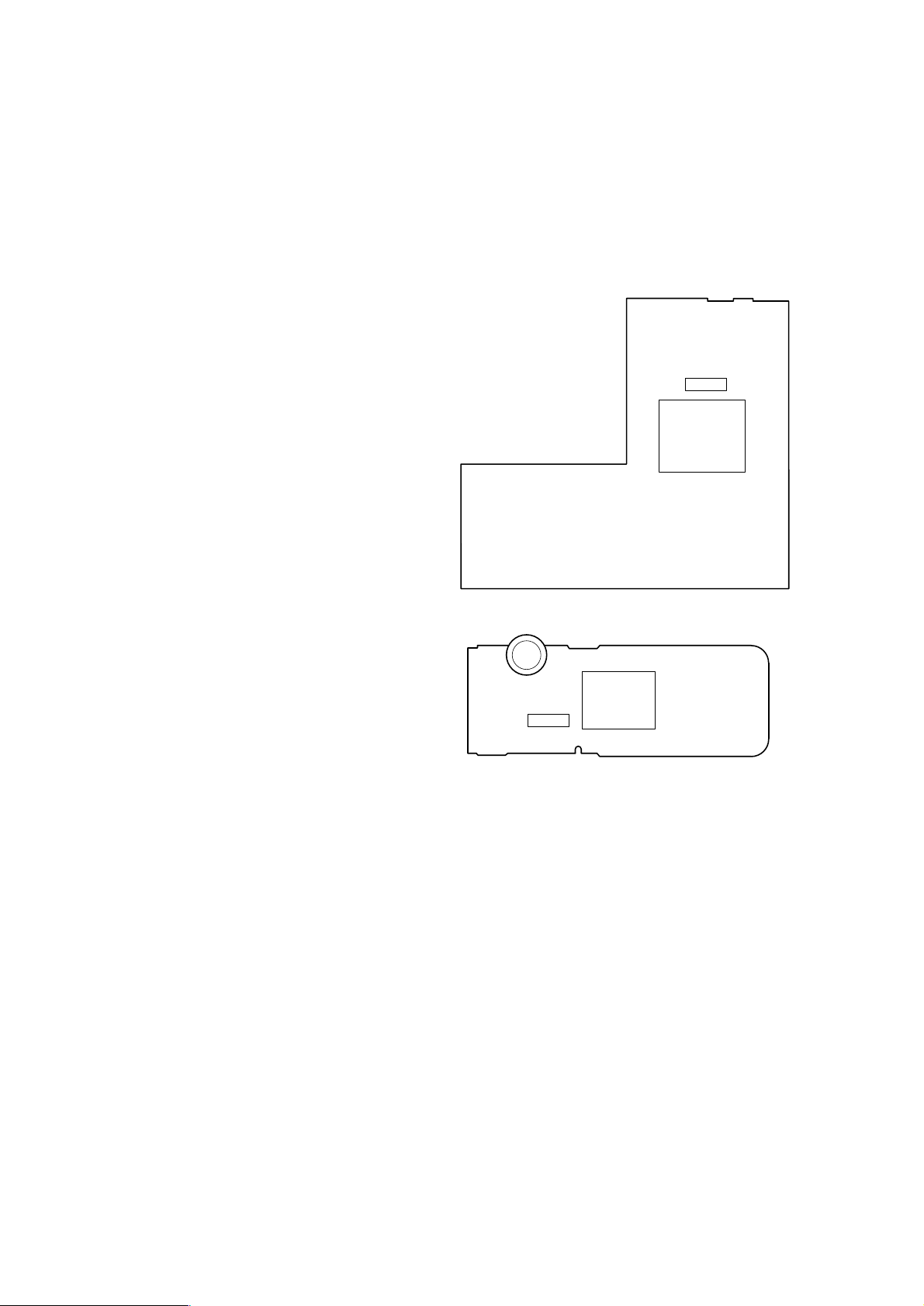
TABLE OF CONTENTS
Specifications ........................................................................... 1
1. GENERAL
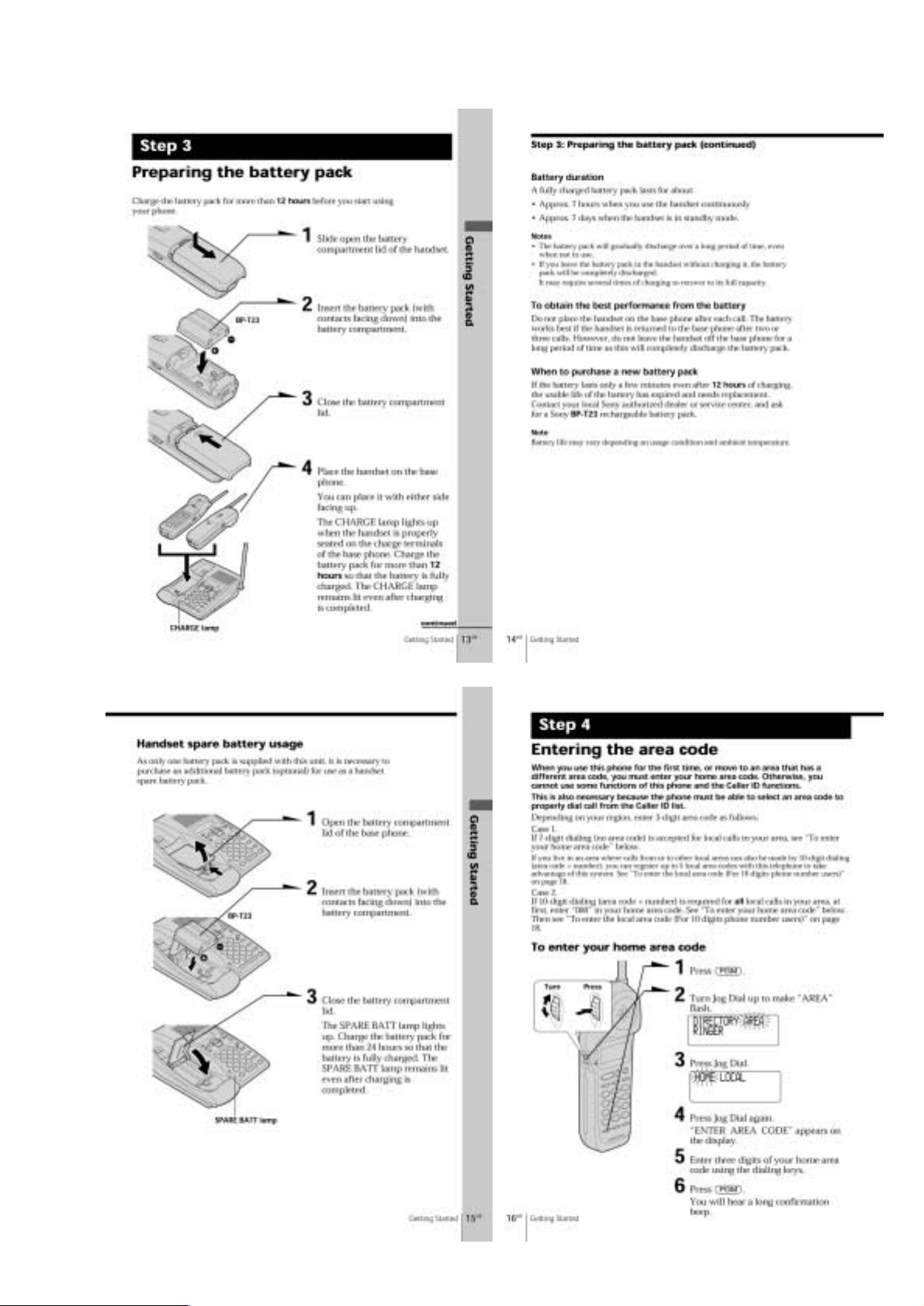
Identifying the Parts ............................................................. 3
Checking the Package Contents ........................................... 4
Setting Up the Base Phone ................................................... 4
Preparing the Battery Pack ................................................... 5
Entering the Area Code ........................................................ 5
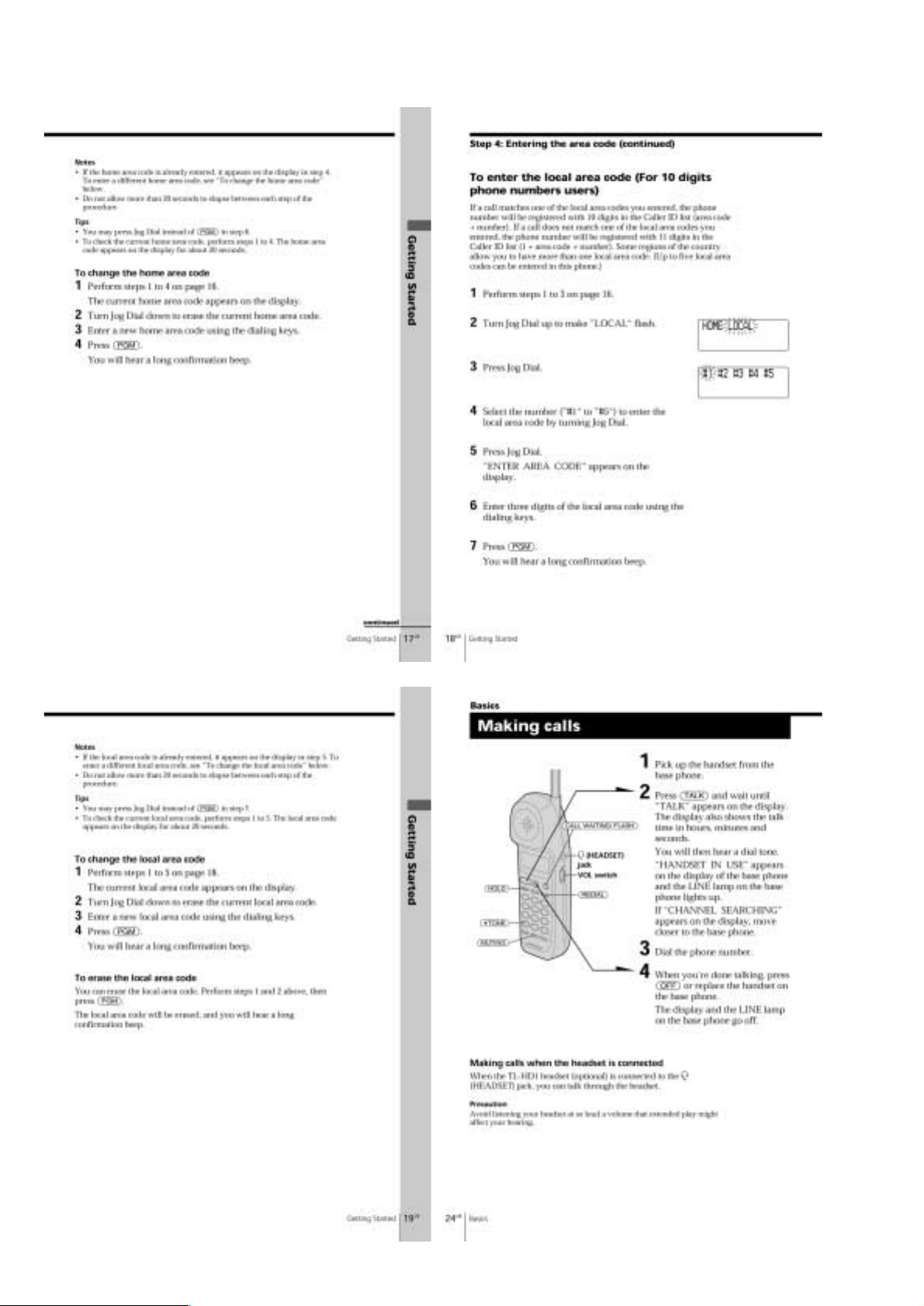
Making Calls ........................................................................ 6
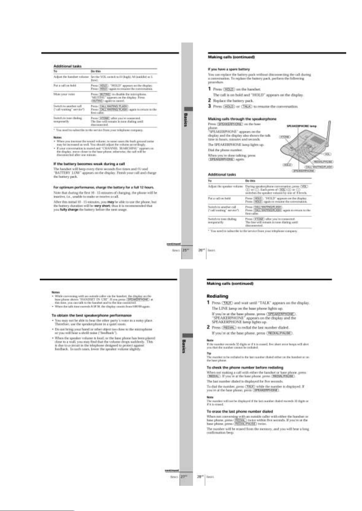
Receiving Calls .................................................................... 8
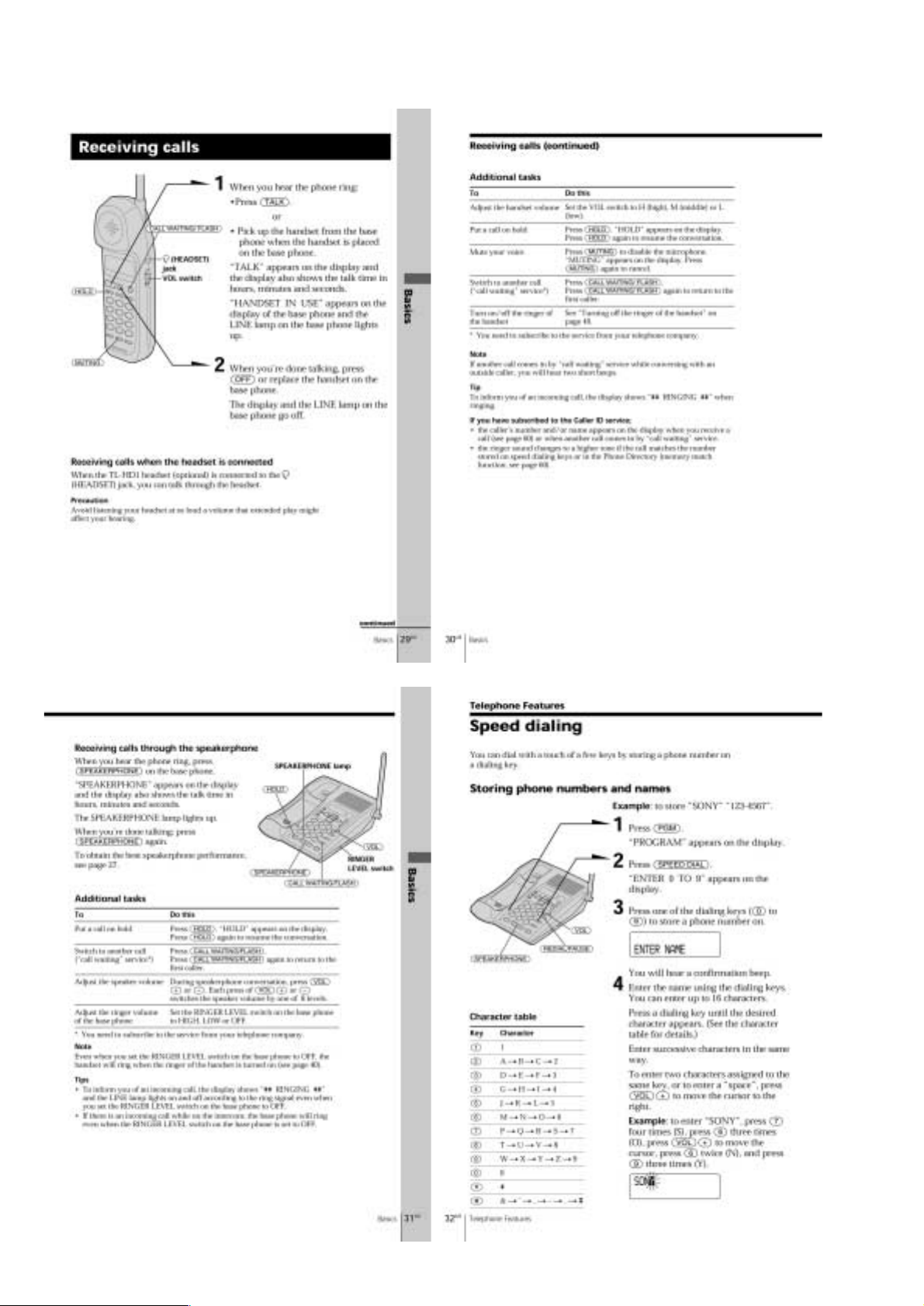
Speed Dialing ....................................................................... 8
Phone Directory................................................................... 9
Setting the Ringer Type ...................................................... 10
Switching the Phones During a Call....................................11
Talking Between the Phones (Intercom) .............................11
Transferring a Call...............................................................11
Setting Up the Answering Machine.................................... 12
Playing Back Messages ...................................................... 14
Selecting the Announcement Only Mode........................... 14
Screening Calls ................................................................... 14
Recording a Memo Message .............................................. 15
Operating From an Outside Phone ..................................... 15
Understanding the Caller ID Service.................................. 15
Looking at the Caller ID List ............................................. 16
Using the Caller ID List ..................................................... 16
Using “Caller ID with Call Waiting” Service..................... 17
Note for Replacement of the ASIC Board
The ID is written in the ASIC board.
When replacing the ASIC board, the U3003 on BASE MAIN board
and U1001 on HAND MAIN board should be replaced together as
a pair.
NOTE FOR REPLACEMENT OF THE EEPROM
When replacing the EEPROM, U3007 on the BASE MAIN
board and U1006 on HAND MAIN board should be replaced
together as a pair.
– BASE MAIN BOARD (SIDE A) –
U3007
U3003
2. DISASSEMBLY
2-1. H/S Rear .................................................................... 18
2-2. “RF Unit ASSY, Hand”, Hand Main Board............... 18
2-3. Base Bottom ............................................................. 19
2-4. Base Main Board ...................................................... 19
2-5. RF Unit ASSY, Base .................................................. 20
2-6. Base Key Board, LCD Board .................................... 20
3. ELECTRICAL ADJUSTMENTS
Base Unit ............................................................................ 21
Handset .............................................................................. 23
4. DIAGRAMS
4-1. Block Diagram – Base Unit Section –....................... 25
4-2. Block Diagram– Handset Section –........................... 27
4-3. Schematic Diagram – Base Main Board (1/2) –....... 29
4-4. Schematic Diagram – Base Main Board (2/2) –....... 31
4-5. Printed Wiring Board– Base Main Board (1/2) –..... 33
4-6. Printed Wiring Board– Base Main Board (2/2) –..... 35
4-7. Printed Wiring Board– Base Key Board (1/2) –....... 37
4-8. Printed Wiring Board– Base Key Board (2/2) –....... 39
4-9. Schematic Diagram – Base Key Board – ................. 41
4-10.Printed Wiring Board – Hand Main Board –............. 43
4-11.Schematic Diagram – Hand Main Board (1/2) – ...... 45
4-12.Schematic Diagram – Hand Main Board (2/2) – ...... 47
5. EXPLODED VIEWS
5-1. Handset Section ......................................................... 49
5-2. Base Unit Section ...................................................... 50
6. ELECTRICAL PARTS LIST .................................... 51
– HAND MAIN BOARD (SIDE B) –
U1001
U1006
Flexible Circuit Board Repairing
• Keep the temperature of the soldering iron around 270°C during
repairing.
• Do not touch the soldering iron on the same conductor of the
circuit board (within 3 times).
• Be careful not to apply force on the conductor when soldering or
unsoldering.
Notes on chip component replacement
• Never reuse a disconnected chip component.
• Notice that the minus side of a tantalum capacitor may be damaged by heat.
SAFETY-RELATED COMPONENT WARNING!!
COMPONENTS IDENTIFIED BY MARK ! OR DOTTED LINE WITH
MARK !ON THE SCHEMATIC DIAGRAMS AND IN THE PARTS
LIST ARE CRITICAL TO SAFE OPERATION.
REPLACE THESE COMPONENTS WITH SONY PARTS WHOSE
PART NUMBERS APPEAR AS SHO WN IN THIS MANUAL OR IN
SUPPLEMENTS PUBLISHED BY SONY.
– 2 –
SECTION 1
GENERAL
This section is extracted from
instruction manual.
– 3 –
– 4 –
– 5 –
– 6 –
– 7 –
– 8 –
– 9 –
– 10 –
– 11 –
– 12 –
– 13 –
– 14 –
 Loading...