

Page 1
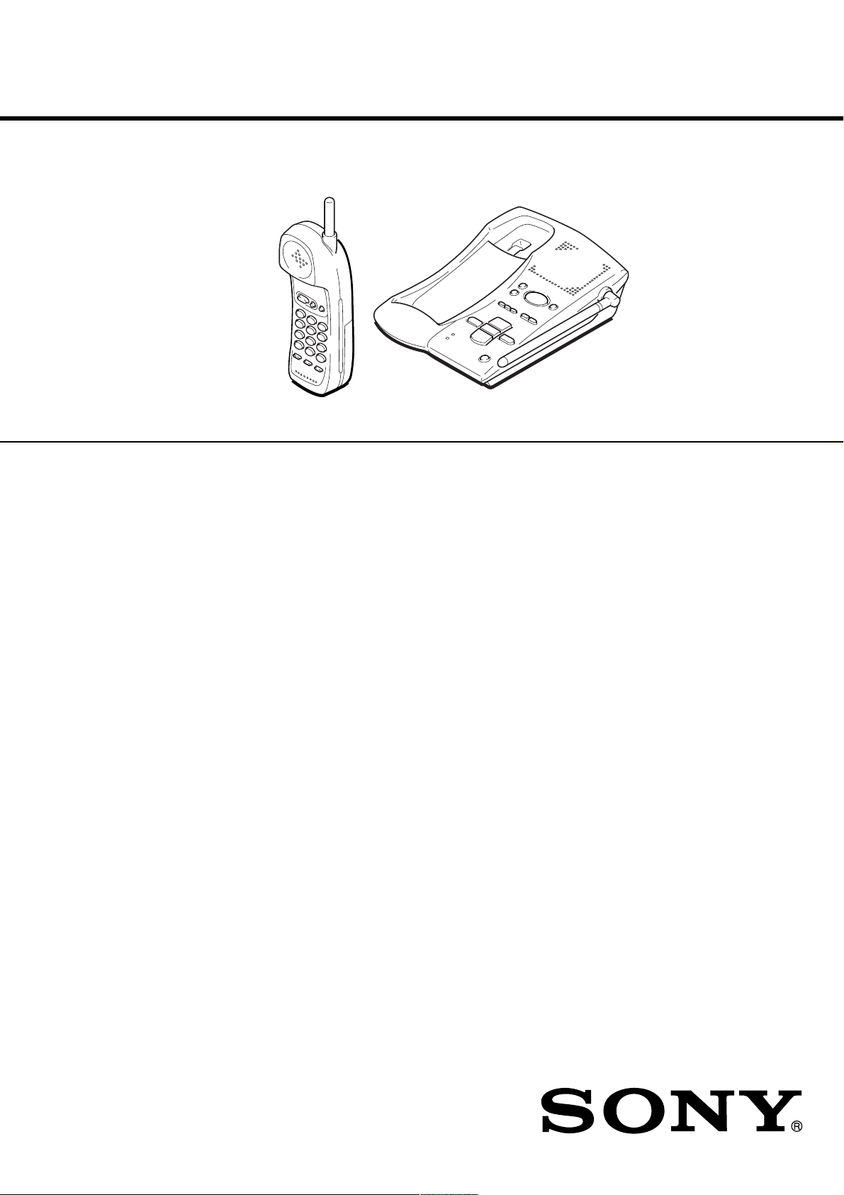
SPP-A941
pp
SERVICE MANUAL
Ver 1.0 2000. 09
SPECIFICATIONS
General
Frequency band
902 - 928 MHz
Operating channel
30 channels
Dial signal
Tone, 10 PPS (pulse) selectable
Supplied accessories
AC power adaptor (AC-T130)
Telephone line cords (2)
Wall bracket for base unit
Rechargeable battery pack (BP-T23)
Handset
Power source
Rechargeable battery pack BP-T23
Battery charging time
Approx. 10 hours
Battery life
Standby: Approx. 6 days
Talk: Approx. 7 hours
Dimensions
Approx. 56 x 183 x 43 mm (w/h/d),
antenna excluded
(approx. 2
Antenna: Approx. 32 mm
(approx. 1
Mass
Approx. 230 g
(a
1
⁄4 x 7 1⁄4 x 1 3⁄4 inches)
1
⁄4 inches)
rox. 8 oz), battery included
Mexican Model
Base unit
Power source
DC 9V from AC power adaptor
AC-T130
Battery charging time
Approx. 24 hours
Dimensions
Approx. 155 x 60 x 220 mm (w/h/d),
antenna excluded
(approx. 6
Antenna: Approx. 120 mm
(approx. 4
Mass
Approx. 520 g
(approx. 1 lb 2 oz), wall bracket excluded
Answering machine
Maximum recording time
About 15 minutes, using incorporated IC
Greeting message
Up to 90 seconds per each
Incoming and Memo message
Up to 4 minutes per message
Design and specifications are subject to
change without notice.
1
⁄8 x 2 3⁄8 x 8 3⁄4 inches)
3
⁄ 4 inches)
CORDLESS TELEPHONE WITH ANSWERING SYSTEM
Page 2

TABLE OF CONTENTS
1. GENERAL
Identifying the parts ........................................................ 3
Setting up the base unit ................................................... 4
Preparing the battery pack .............................................. 4
Making Calls ................................................................... 5
Receiving Calls ............................................................... 5
Telephone Features ......................................................... 6
Answering Machine Features ......................................... 7
2. DISASSEMBLY ......................................................... 11
3. TEST MODE.............................................................. 13
4. ELECTRICAL ADJUSTMENTS
Base Unit ......................................................................... 14
Handset ............................................................................ 16
5. DIAGRAMS
5-1. Block Diagram – BASE UNIT Section –...................... 17
5-2. Block Diagram – HANDSET Section – ........................ 19
5-3. Note for Printed Wiring Boards and
Schematic Diagrams ....................................................... 21
5-4. Printed Wiring Board – BASE MAIN Board – ............. 23
5-5. Schematic Diagram – BASE MAIN Board –................ 25
5-6. Printed Wiring Board – BASE KEY Board – ............... 28
5-7. Schematic Diagram – BASE KEY Board – .................. 29
5-8. Printed Wiring Board – HAND MAIN Board – ........... 30
5-9. Schematic Diagram – HAND MAIN Board – .............. 31
5-10. IC Pin Function Description ........................................... 33
Notes on chip component replacement
• Never reuse a disconnected chip component.
• Notice that the minus side of a tantalum capacitor may be damaged by heat.
SAFETY-RELATED COMPONENT WARNING!!
COMPONENTS IDENTIFIED BY MARK 0 OR DOTTED
LINE WITH MARK 0 ON THE SCHEMA TIC DIAGRAMS
AND IN THE PARTS LIST ARE CRITICAL TO SAFE
OPERATION. REPLACE THESE COMPONENTS WITH
SONY PARTS WHOSE PART NUMBERS APPEAR AS
SHOWN IN THIS MANUAL OR IN SUPPLEMENTS PUBLISHED BY SONY.
6. EXPLODED VIEWS ................................................ 35
7. ELECTRICAL PARTS LIST ............................... 37
– 2 –
Page 3
SECTION 1
GENERAL
This section is extracted from
instruction manual.
Identifying the parts
Refer to the pages indicated in parentheses for details.
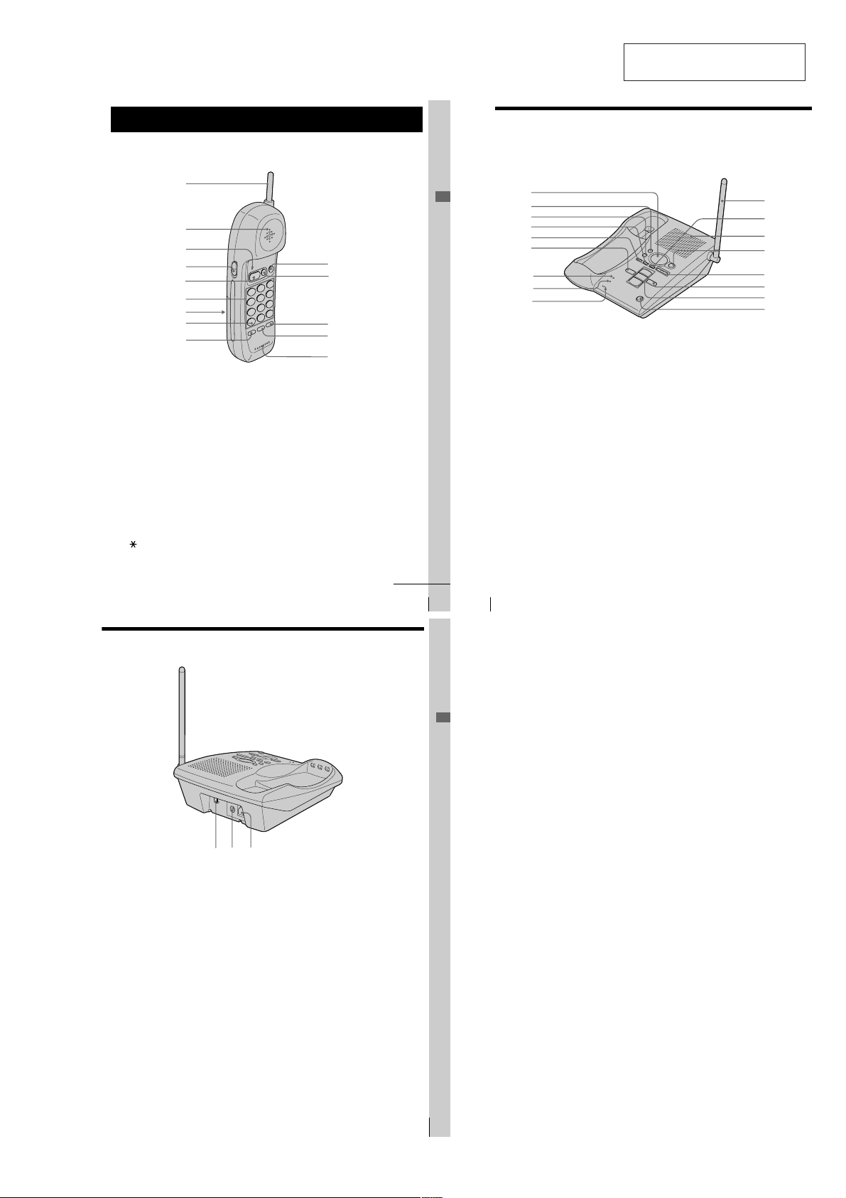
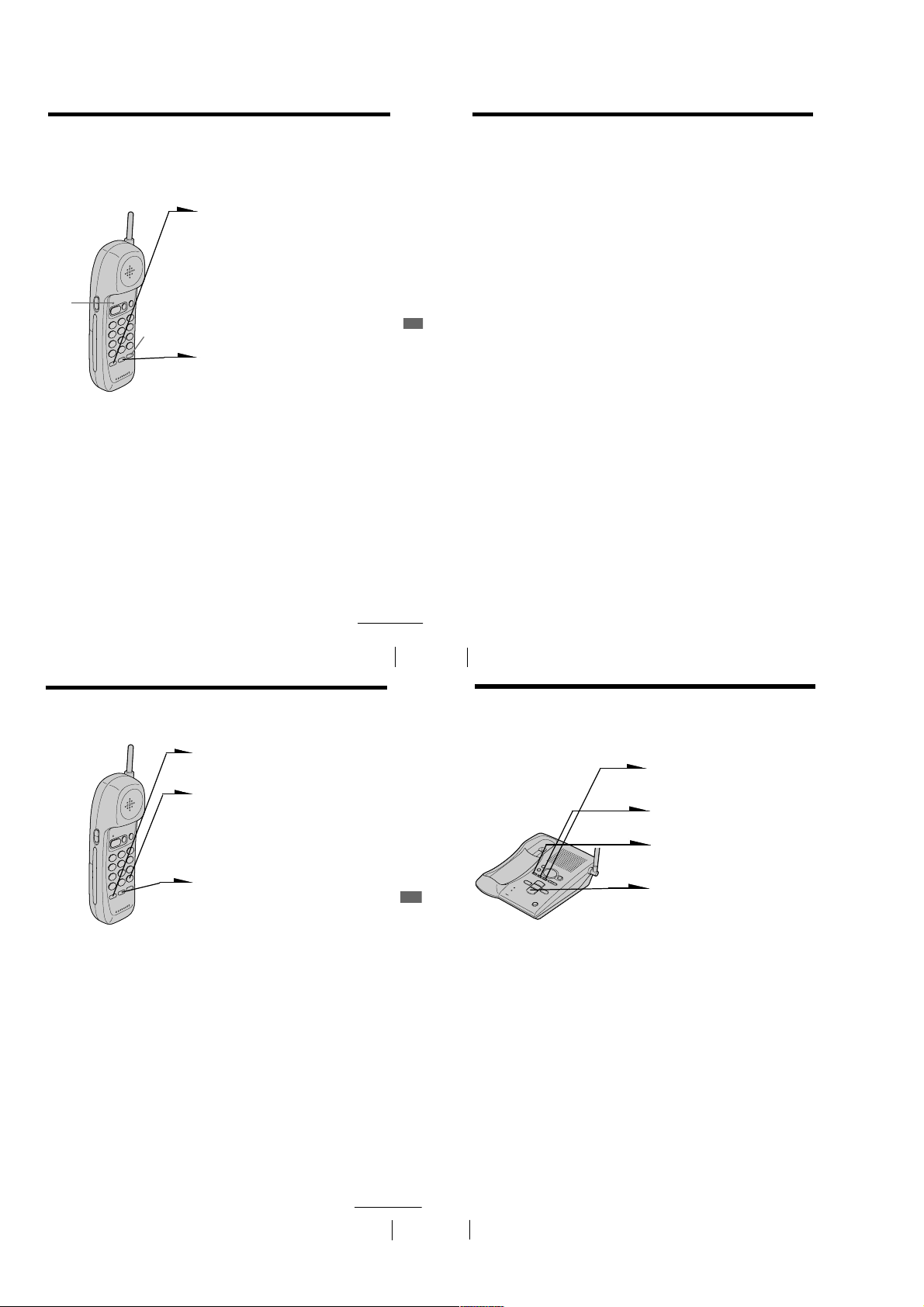
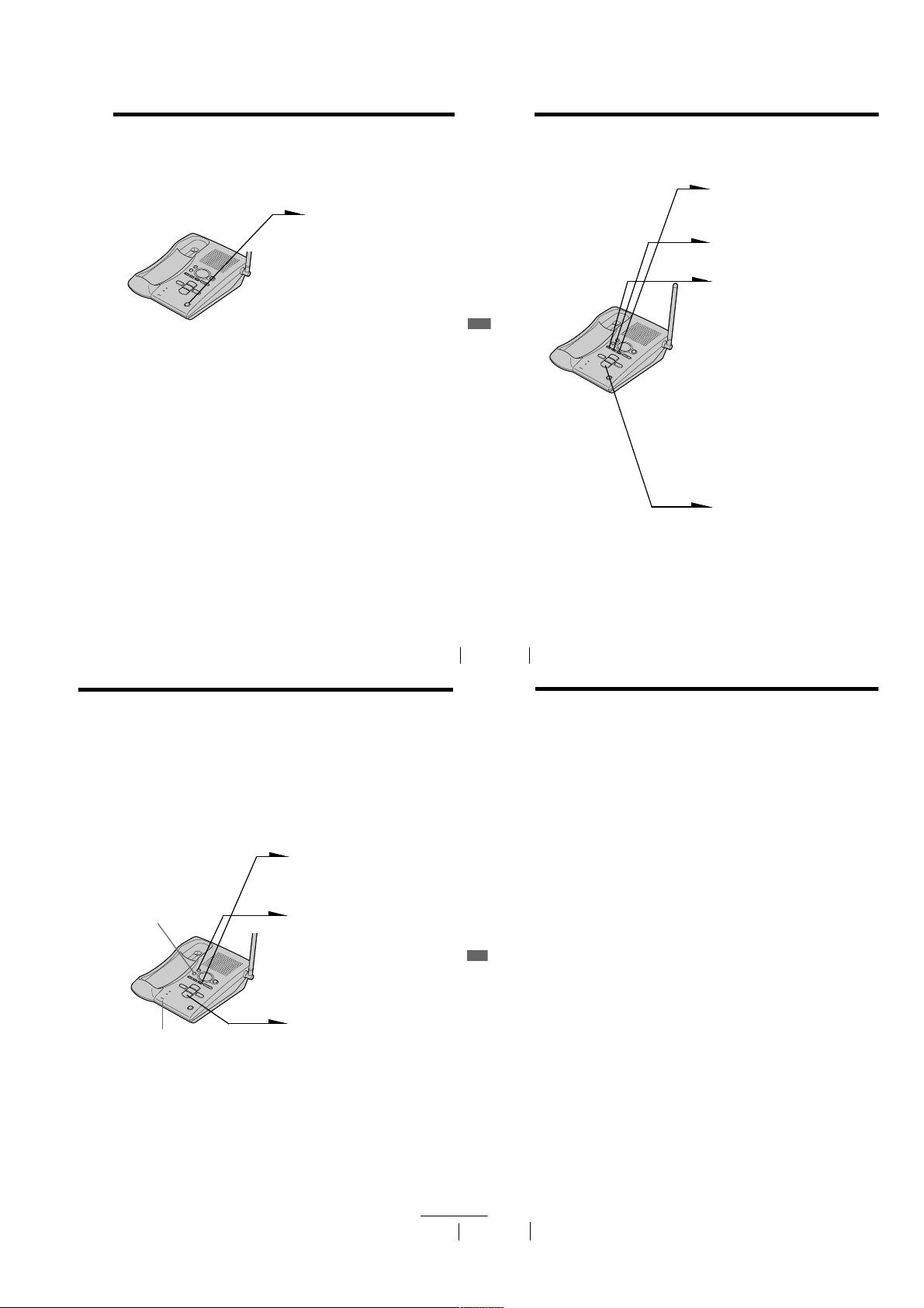
Handset
1
2
3
4
5
6
7
8
9
1 Antenna
2 Speaker
3 TALK/BATT LOW lamp
Lights up during a call, flashes
when you store a phone number for
speed dialing.
4 VOL (volume) switch (p. 16)
Adjusts the handset volume.
5 TALK/FLASH button (p. 16, 18)
Lets you make or receive a call.
6 Dialing keys (p. 16)
7 Battery compartment (p. 11)
TONE button (p. 12, 16)
8
Allows you to switch temporarily to
tone dialing.
9 PGM (Program) button
(p. 12, 21)
Used to store numbers for speed
dialing.
0 CHANNEL button (p. 16)
Used to select a better channel.
qa OFF button (p. 16)
Allows you to disconnect the call.
qs REDIAL/PAUSE button
(p. 17, 20)
Redials the last number called /
inserts a pause in the dialing
sequence.
qd SPEED DIAL button (p. 12, 19)
Used to make a call with speed
dialing.
qf Microphone
Identifying the parts (continued)
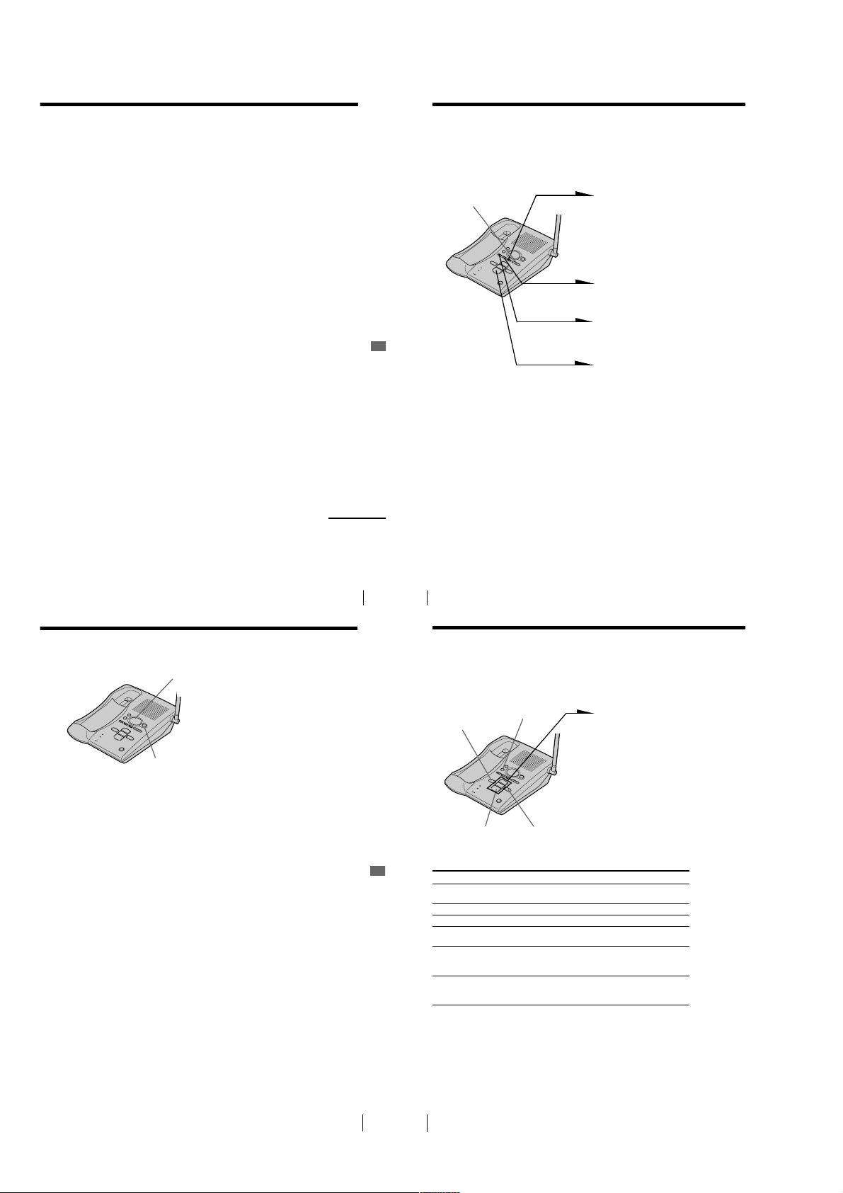
Base Unit
Getting Started
0
qa
qs
qd
qf
continued
Getting Started
US
14
13
1
2
3
4
5
6
7
8
9
1 Message counter ( p . 2 9 )
Indicates the number of new
messages recorded. “A” appears in
the announcement only mode. “F”
appears when there is no space to
record messages.
2 REC/MEMO button (p. 25, 34)
Records a greeting or memo
message.
3 ERASE button (p. 26, 31)
Erases the recorded greeting or
messages.
4 SELECT button (p. 24)
5 TIME/SET button (p. 24, 35)
Press when setting the day and
time, or to check the current time.
Also used when setting the remote
ID code (security code).
US
Getting Started
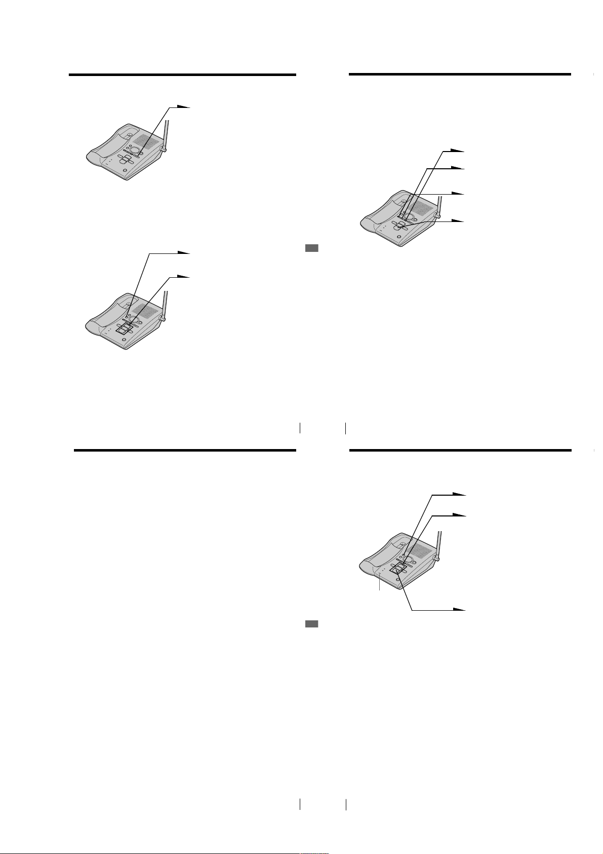
6 REPEAT/SLOW button
(p. 30)
Press to repeat the current message
or go back to the previous message.
Keep the button pressed for slow
playback of messages.
7 CHARGE lamp (p. 11)
Lights while the battery is being
charged.
8 IN USE lamp (p. 18)
Lights when the cordless handset is
in use.
9 MIC (microphone) (p. 25, 34)
0 Antenna (p. 9, 37)
qa MENU button (p. 24)
qs Speaker
0
qa
qs
qd
qf
qg
qh
qj
qd ANSWER ON/OFF button
(p. 29)
Turns the answering function on or
off.
qf VOLUME +/– buttons (p. 31)
Adjusts the speaker volume.
qg SKIP/QUICK button (p. 30)
Press to skip to the next message.
Keep the button pressed for quick
playback of messages.
qh PLAY/STOP (MAILBOX 1, 2, 3)
buttons (p. 30)
Plays back the messages in each
mailbox.
qj HANDSET LOCATOR button
(p. 23)
Allows you to page the cordless
handset.
w;qlqk
qk Hook for AC power adaptor
cord (p. 9)
ql DC IN 9V jack (p. 9, 37)
w; LINE (telephone line) jack
(p. 9, 37)
Getting Started
Getting Started
US
15
– 3 –
Page 4
Step 2
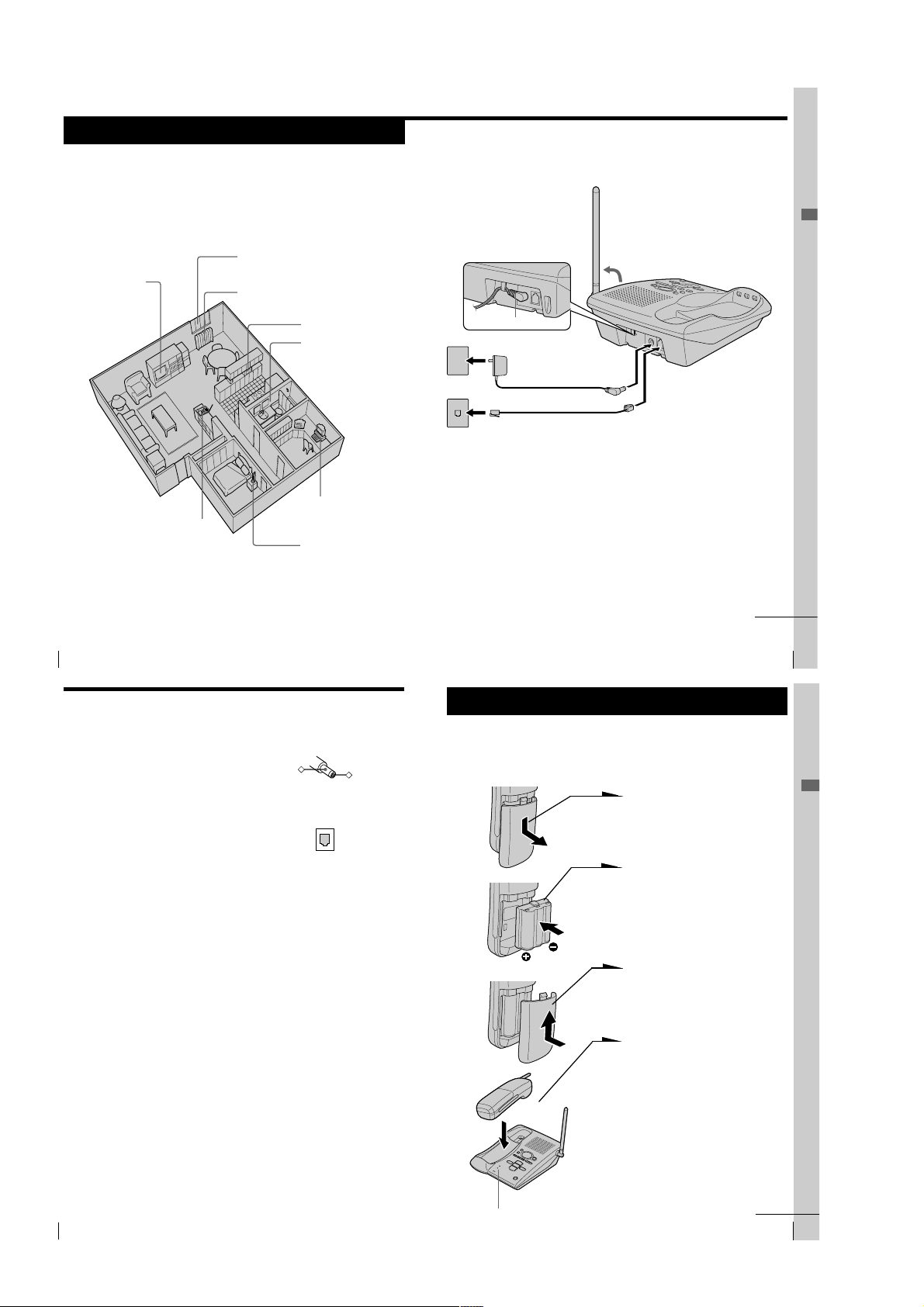
Setting up the base unit
Do the following steps:
• Choose the best location
• Connect the base unit
• Choose the dialing mode
Choose the best location
Where you place the base unit affects the reception quality of the
handset.
Away from television
sets and other
electronic equipment
Near a central location
and on a level surface
CAUTION: • Should you experience intermittent loss of audio during a conversation, try
moving closer to the base or move base unit away from other noise sources.
• The cordless telephone operates at a frequency that may cause interference to
nearby TVs and VCRs; the base unit should not be placed near or on the top of
a TV or VCR; and, if interference is experienced, moving the cordless telephone
farther away from the TV or VCR will often reduce or eliminate the
US
8
interference.
Getting Started
Away from noise sources such as a window
by a street with heavy traffic
Away from heat sources, such as radiators,
airducts, and sunlight
Away from a microwave
oven
Away from excessive
moisture, extremely low
temperatures, dust,
mechanical vibration, or
shock
Away from a personal
computer
Away from another
cordless telephone
Connect the base unit
If you want to hang the base unit on the wall, see page 37.
3
Hook the cord.
To an AC outlet
To the
telephone outlet
2
1
To DC IN 9V
AC power adaptor
(supplied AC-T130)
Telephone line cord
(supplied)
To LINE
1
Connect the telephone line cord
to the LINE jack and to a
telephone outlet.
2
Connect the AC power adaptor
to the DC IN 9V jack and to an
AC outlet.
3
Raise the antenna. Make sure it
points towards the ceiling.
continued
Getting Started
Getting Started
US
9
Step 2: Setting up the base unit (continued)
Notes
• Use only the supplied AC-T130 AC power adaptor.
Do not use any other AC power adaptor.
• Connect the AC power adaptor to a continuous power
supply.
• Place the base unit close to the AC outlet so that you
can unplug the AC power adaptor easily.
Tip
If your telephone outlet is not modular, contact your
telephone service company for assistance.
Polarity of the plug
–
Modular
Step 3
Preparing the battery pack
Charge the battery pack for more than 10 hours before you start using
+
your phone.
BP-T23
1
Slide open the battery
compartment lid of the handset.
2
Insert the battery pack (with
contacts facing down) into the
battery compartment.
3
Close the battery compartment
lid.
4
Place the handset on the base
unit.
The CHARGE lamp lights up
when the handset is properly
seated on the charge terminals
of the base unit. Charge the
battery pack for more than 10
hours so that the battery is fully
charged. The CHARGE lamp
remains lit even after charging
is completed.
Getting Started
US
10
Getting Started
– 4 –
CHARGE lamp
continued
Getting Started
US
11
Page 5
Step 3: Preparing the battery pack (continued)
Basics
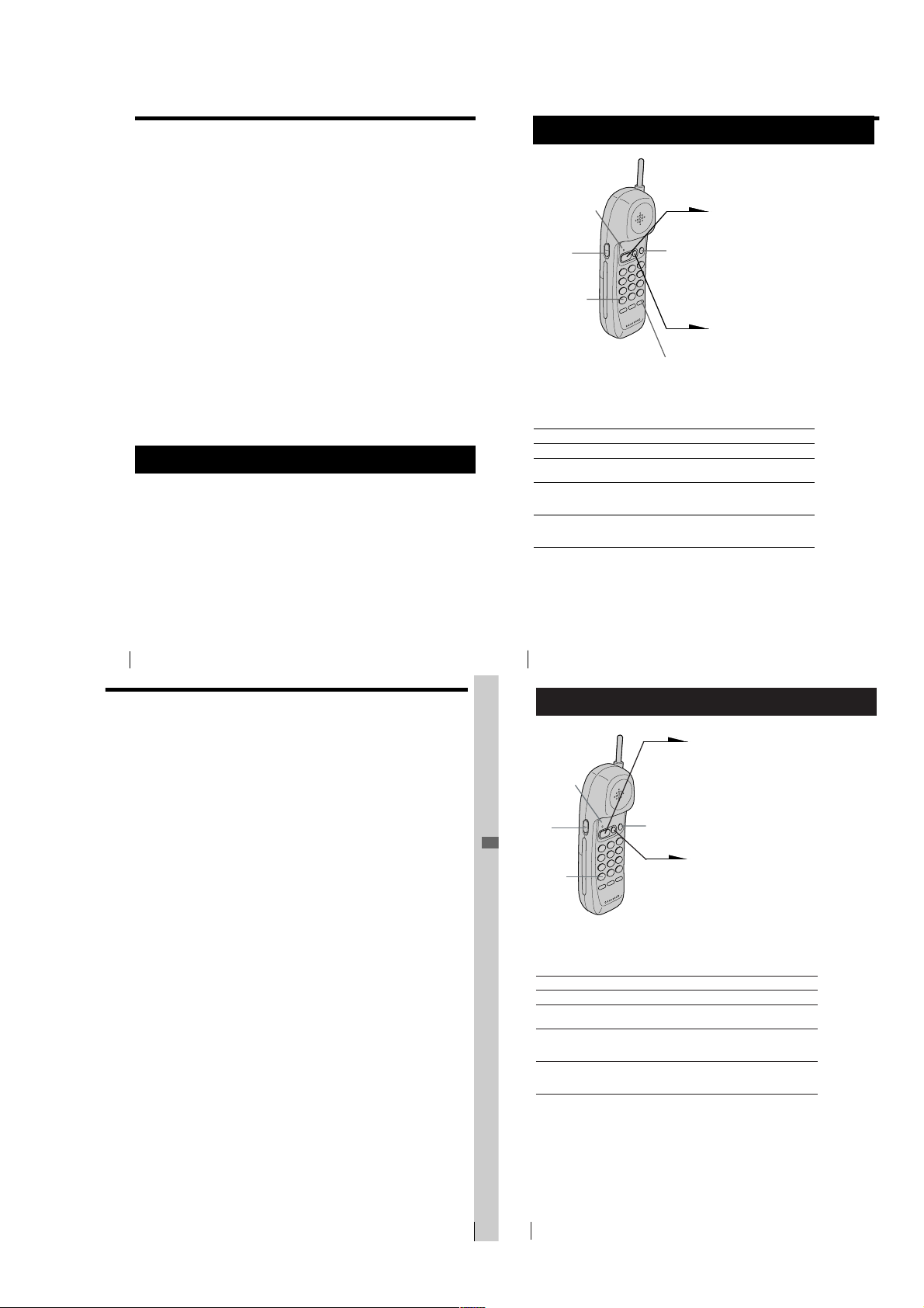
Making calls
Battery duration
A fully charged battery pack lasts for about:
• Approx. 7 hours when you use the handset continuously
• Approx. 6 days when the handset is in standby mode.
Notes
• The battery pack will gradually discharge over a long period of time, even if
not in use.
• If you leave the battery pack in the handset without charging it, the battery
pack will be completely discharged.
It may require several times of charging to recover its full capacity.
To obtain the best performance from the battery
Do not place the handset on the base unit after each call. The battery
works best if the handset is returned to the base unit after two or three
calls. However, do not leave the handset off the base unit for a long
period of time as this will completely discharge the battery pack.
When to purchase a new battery pack
If the battery lasts only a few minutes even after 10 hours of charging,
the usable life of the battery has expired and needs replacement.
Contact your local Sony authorized dealer or service center, and ask
for a Sony BP-T23 rechargeable battery pack.
Note
Battery life may vary depending on usage condition and ambient temperature.
Step 4
Choosing the dialing mode
For the telephone to work properly, select an appropriate dialing mode
(tone or pulse). The default setting is tone.
1
Press (PGM).
The TALK/BATT LOW lamp flashes.
2
Press (*TONE).
3
Press (#) for pulse dialing or (*TONE) for tone dialing.
4
Press (SPEED DIAL).
You hear a confirmation beep and the TALK/BATT LOW lamp goes off.
US
Getting Started
12
1
Pick up the handset from the
base unit.
TALK/BATT
LOW lamp
VOL
switch
(*TONE)
(CHANNEL)
(REDIAL/PAUSE)
2
Press (TALK/FLASH).
TALK/BATT LOW lamp lights
up, then you’ll hear a dial tone.
If you hear beeps, move closer
to the base unit.
3
Dial the phone number.
4
When you’re done talking, press
(OFF) or replace the handset on
the base unit.
The TALK/BATT LOW lamp
goes off.
Additional tasks
To
Select a better channel
Adjust the handset
volume
Switch to tone dialing
temporarily
Switch to another call
(“call waiting” service*)
*Contact your telephone company to subscribe to this service.
Notes
• Before dialing, make sure you can hear the dial tone, otherwise you cannnot
dail correctly.
• When the TALK/BATT LOW lamp lights up by pressing (TALK/FLASH) , the
IN USE lamp on the base unit lights up simultaneously.
US
Basics
16
Do this
Press (CHANNEL).
Set the VOL switch to H (high), M (middle) or L
(low).
Press (*TONE) while using the telephone after
you’re connected. The line remains in tone dialing
until disconnected.
Press (TALK/FLASH) to access the flash function.
Press (TALK/FLASH) again to return to the first
caller.
If the handset battery becomes weak during a call
You hear a beep every three seconds and the TALK/BATT LOW lamp
on the handset flashes.
The call will disconnect soon. Replace the handset on the base unit to
charge.
For optimum performance, charge the battery for a full 10 hours.
Note that during the first 10 - 15 minutes of charging, the phone will be
inactive, i.e., unable to make or receive a call.
After this initial 10 - 15 minutes, you may be able to use the phone, but
the battery duration will be very short; thus it is recommended that
you fully charge the battery before the next usage.
Redialing
1
Press (TALK/FLASH).
The TALK/BATT LOW lamp lights up.
2
Press (REDIAL/PAUSE) to redial the number last dialed.
Note
If the number last dialed exceeds 16 digits, only the first 16 digits are dialed.
Basics
Receiving calls
1
When you hear the phone ring;
• Press (TALK/FLASH)
TALK/BATT
LOW lamp
VOL
switch
(*TONE)
(CHANNEL)
Additional tasks
To
Select a better channel
Adjust the handset
volume
Switch to tone dialing
temporarily
Switch to another call
(“call waiting” service*)
*Contact your telephone company to subscribe to this service.
Do this
Press (CHANNEL).
Set the VOL switch to H (high), M (middle) or L
(low).
Press (*TONE) while using the telephone after
you’re connected. The line remains in tone dialing
until disconnected.
Press (TALK/FLASH) to access the flash function.
Press (TALK/FLASH) again to return to the first
caller.
(or any key except (OFF)) .
• Pick up the handset from the base
unit when the handset is placed on
the base unit.
The TALK/BATT LOW lamp lights up
at the same time the IN USE lamp on
the base unit lights up.
2
When you’re done talking, press
(OFF) or replace the handset on the
base unit.
The TALK/BATT LOW and IN USE
lamps go off.
or
Basics
US
17
– 5 –
US
Basics
18
Page 6
Telephone Features
Speed dialing
Speed dialing (continued)
You can dial with a touch of a few buttons by storing a phone number
on a dialing button. You can store up to 10 different phone numbers.
Storing phone numbers
1
Press (PGM).
The TALK/BATT LOW lamp flashes.
2
Press one of the dialing buttons ((0)
to (9)) for the phone number to be
stored.
3
Enter the phone number you want to
TALK/
BATT LOW
lamp
Notes
• In step 3, if you don’t enter the phone number, the previously stored number
will be erased.
• Do not allow more than 30 seconds to elapse between each step of the
procedure.
• Before storing phone numbers, make sure the handset is not in use.
Tips
• If you enter a wrong number, start from the beginning.
• Use the supplied directory to write down what you stored on the speed
dialing numbers.
(REDIAL/PAUSE)
store.
You can enter up to 16 digits,
including a tone and a pause, each of
which is counted as one digit.
4
Press (SPEED DIAL).
You’ll hear a confirmation beep, and
the number is stored. The TALK/
BATT LOW lamp goes off.
To store the previous number dialed
Press (REDIAL/PAUSE) directly after step 2, then go to step 4.
To store a number to be dialed via Private Branch Exchange (PBX)
Before entering a phone number in step 3 on page 19, do as follows:
1
Enter the outside line access digit (e.g. 9).
2
Press (REDIAL/PAUSE).
To change a stored number
To store a new number, follow the instructions described previously.
Making calls with speed dialing
1
Press (TALK/FLASH).
The TALK/BATT LOW lamp lights up.
2
Telephone Features
Press (SPEED DIAL).
3
Enter the desired speed dialing number ((0) to (9)).
The phone number stored in the speed dialing number will be dialed.
Setting the ringer type
You can select a ringer type from four types.
1
Press (PGM).
2
Press (#).
3
Press a number button, (1) to (4), to
select a ringer type.
4
Press (SPEED DIAL).
Turning off the ringer
1
Press (PGM).
2
Press (#).
3
Press (5).
4
Press (SPEED DIAL).
The ringer on the handset is turned off.
To turn the ringer on again
Follow the instructions described in “Setting the ringer type.”
Checking the ringer type
1
Press (PGM).
2
Press (#).
3
Press (0).
The currently selected ringer sounds.
4
Press (SPEED DIAL).
Note
If you hear no sound (only key beep), the ringer on the handset has been turned
off.
continued
Telephone Features
continued
Telephone Features
US
19
US
Telephone Features
20
Setting the ringer type (continued)
Setting the base ringer
Telephone Features
Note
The base ringer is preset to on.
US
21
US
Telephone Features
22
1
Press (MENU) until you hear
“Set base ringer”.
“- -” blinks on the display.
2
Press (SELECT) to turn the
ringer on or off.
3
Press (TIME/SET).
The base ringer setting is
announced.
4
Press (PLAY/STOP) to exit the
menu set up mode.
– 6 –
Page 7
Paging
Answering Machine Features
Setting up the answering machine
You can page the handset from the base unit.
Note that you cannot page if the handset is in use.
To Page
Press (HANDSET LOCATOR).
The handset rings for about one
minute.
To stop ringing, press (OFF) o n
the handset.
Tips
• You can page the handset even when “RINGER” is set to “RINGER OFF”.
• To stop ringing at the base unit, press (HANDSET LOCATOR).
Note
If a call comes in paging, paging is cancelled.
Telephone Features
Setting the time and day of the week
Telephone Features
Notes
• Press and hold (SELECT) to increase the minute setting by 10.
• The time and day are preset to Monday, 12:00 AM.
• “CL” flashes when the day and time is cleared or delayed due to a power
interruption, or when you connect the base unit to the AC outlet for the first
time.
US
US
23
Answering Machine Features
24
1
Press (MENU) repeatedly until
you hear “Set day and time”.
“- -” blinks on the display.
2
Press (SELECT) repeatedly to
select the day of the week.
3
Press (TIME/SET).
The day is set and the hour is
announced.
4
Press (SELECT) repeatedly to
select the hour.
5
Press (TIME/SET).
The hour is set and the minute is
announced.
6
Press (SELECT) repeatedly to
select the minute.
7
Press (TIME/SET).
The day and time you just
entered is announced and the
clock restarts.
8
Press (PLAY/STOP) to exit the
menu setup mode.
You will hear a long
confirmation beep.
Tip
All the mailbox buttons ( (MAILBOX 1), (MAILBOX 2) and (MAILBOX 3)) work as
the (PLAY/STOP) button; press any of the three in this case.
To hear the current time
Press (TIME/SET). The current time setting is announced.
Recording the greeting
You can record your own greeting for the “normal” and
“announcement only” modes (see page 32).
1
Press (MENU) repeatedly until
“Set out-going message” is
announced.
“- -” blinks on the display.
(ERASE)
MIC
Notes
• If you do not record your own greeting, the prerecorded greeting will be
assigned automatically (see page 26).
• If your greeting is less than two seconds, the greeting is not recorded. The
prerecorded greeting will be assigned automatically.
• If a call comes in during recording, recording stops automatically.
• If 90 seconds have passed or memory becomes full in step 3, recording stops
automatically.
• “Memory full” is announced if no recording space is available when you
press (REC/MEMO). Erase unnecessary messages (see page 31).
Tip
To record a greeting for the “announcement only” mode, select the
announcement only mode first (see page 32), then follow the instructions above.
Otherwise, the normal greeting will be recorded.
2
Press (REC/MEMO).
“Now recording” is announced
and a long beep sounds.
3
Speak into the base unit
microphone (MIC). The display
starts counting. You can record
up to 90 seconds.
4
To stop recording, press
(PLAY/STOP).
Your greeting replays
automatically.
Answering Machine Features
continued
Setting up the answering machine (continued)
To check the greeting
Press (MENU) repeatedly until “Set out-going message” is announced.
Then press (PLAY/STOP) to play back the greeting.
To change the greeting
Record a new greeting by following the instructions on the previous
page. The new greeting replaces the old one.
To erase the greeting
1
Press (MENU) repeatedly until “Set out-going message” is
announced.
2
Press (ERASE).
Notes
• You can also erase the greeting during playback.
• If you have erased your own greeting, the prerecorded greeting will be
assigned automatically.
Answering Machine Features
US
25
Prerecorded greetings
Normal mode: “Hello, I’m unable to answer your call
Announcement only mode: “Hello, I’m unable to answer your call
US
Answering Machine Features
26
right now. Please leave your name,
number and message after the tone.”
right now. Please call again. Thank you.”
– 7 –
Page 8
Setting up the answering machine (continued)
Setting the number of rings
You can select the number of times the phone rings before it answers
to take a message.
There are four modes: 2, 4, 6, and Toll Saver.
1
Press (MENU) repeatedly until you hear “Set number of
rings”.
“- -” blinks on the display.
2
Press (SELECT) repeatedly to select a ring duration (2, 4, 6,
or Toll Saver).
To answer after 2 rings, select “2”.
To answer after 4 rings, select “4”.
To answer after 6 rings, select “6”.
Select “Toll Saver” to answer after 2 rings when there are
new messages, and 4 rings where there are no new
messages.
3
Press (TIME/SET).
The ring duration setting is announced.
4
Press (PLAY/STOP) to exit the menu setup mode.
Notes
• When the number of rings is set to “Toll Saver”, the phone answers after 2
rings if new messages are recorded. If no new message are recorded, it
answers after 4 rings. When you hear 3 rings, you will know that there are no
new messages. You can save the toll for the call when you pick up messages
from an outside phone.
• The number of rings is preset to 4 rings.
continued
Setting the audible message alert
You have the option of having a beep tell you if you have received any
new incoming messages.
(VOLUME)
Answering Machine Features
Notes
• When the audible message alert is turned on, you will hear a beep every 10
seconds if there are any new messages.
• To stop the beep, press any button related to the answering machine function
or (VOLUME)(+)/(
• The audible message alert is preset to off.
1
Press (MENU) repeatedly until
you hear “Set audible message
alert”.
“- -” blinks on the display.
2
Press (SELECT) to set the
audible message alert on or off.
3
Press (TIME/SET).
The setting is announced.
4
Press (PLAY/STOP) to exit the
menu setup mode.
-
).
Answering Machine Features
Turning on the answering function
Message counter
(ANSWER ON/OFF)
Mailbox usage
This phone offers you three voice mailboxes, providing a convenient way to share the
mailbox feature with other members of your household or business.
When a caller calls
The caller can choose one of the two ways to leave a message:
• If calling from a touch-tone phone, the caller select a mailbox by pressing (*)(1)
(MAILBOX 1), (*)(2) (MAILBOX 2) or (*)(3) (MAILBOX 3) while the caller hears
the greeting. The greeting stops and a beep will sound, then the caller can start
recording a message
• Wait until the greeting finishes, then start recording a message. When the caller
does not select a mailbox, the message is automatically recorded to MAILBOX 1.
Notes
• If four minutes have passed while recording the incoming message, the line will be
disconnected automatically.
• If the message is shorter than two seconds, it will not be recorded.
To turn off the answering function
Press (ANSWER ON/OFF) on the base unit.
The ANSWER ON/OFF button goes off.
Note
The answering function is preset to on.
Tip
The answering machine will automatically answer a call after 10 rings, even if the answering
function is off and announces “Please enter your security code” to prompt the caller to turn on
the answering function.
When the memory is full
The total recording time of this answering machine is approximately 15 minutes
(including the greeting, messages, and memo).
When the remaining recording time becomes less than 30 seconds, “F” flashes on the
display and the answering machine goes into the memory full status.
In this status, the answering machine will not answer a call until after 10 rings even if
the answering function is on.
To avoid this erase unnecessary messages (see page 31). You can also erase the
messages from an outside phone (see page 36).
Press (ANSWER ON/OFF) on the
base unit.
The ANSWER ON/OFF button
lights up.
Answering Machine Features
US
27
US
Answering Machine Features
28
Playing back messages
If there are new messages, the display flashes the number of new
messages.
You will hear beeps if the audible message alert setting is on (see page 28).
(REPEAT/SLOW)
(PLAY/STOP) (SKIP/QUICK)
Additional tasks when playing back messages
Answering Machine Features
US
29
To
Stop playback
Repeat the current message
Skip the current message
Go back to the previous message
Play back slowly
Play back quickly
Notes
• If a call comes in, the play back will stop.
• A time and day stamp is announced after each message.
Tips
• If there are no new messages, all the previously reviewed messages are
played back.
• The messages are saved even after a power failure.
US
Answering Machine Features
30
(ERASE)
Do this
Press a mailbox button ((MAILBOX 1),
(MAILBOX 2) or (MAILBOX 3)).
Press (REPEAT/SLOW) during play back.
Press (SKIP/QUICK).
Press (REPEAT/SLOW) within the first two
seconds of the current message playback.
Press and hold (REPEAT/SLOW) during play
back.
Release (REPEAT/SLOW) to return to normal.
Press and hold (SKIP/QUICK) during play
back.
Release (SKIP/QUICK) to return to normal.
Press a mailbox button
((MAILBOX 1), (MAILBOX 2) or
(MAILBOX 3)) to play back new
messages in the selected mailbox.
– 8 –
Page 9
Adjusting the speaker volume
To adjust the speaker volume, press
(VOLUME)(+) or (
Notes
• When you have reached the minimum or maximum volume level, you will
hear three short beeps.
• You cannot adjust the speaker volume while the phone is ringing.
Tip
There are 8 steps for the volume level (1 to 8). The volume level is preset to 5.
Erasing messages
1
Press and hold (ERASE) for
more than two seconds.
2
Press a button for the mailbox
you want to erase ( (MAILBOX 1),
(MAILBOX 2) or (MAILBOX 3)).
You will hear a long
confirmation beep and all “old”
messages in the selected
mailbox are erased.
To erase individual messages
Press (ERASE) while playing back the message that you want to erase.
Note
The display shows the total number of “new” (i.e. unreviewed) messages.
Therefore, the display is reset to “0” when you have played back all new
messages, whether they have been erased or not. Be sure to erase unnecessary
messages before the memory becomes full.
Answering Machine Features
Selecting the Announcement Only
Mode
-
).
Answering Machine Features
US
31
You can set the answering machine to play the greeting without
recording incoming messages (announcement only mode). You might
want to select this mode when, for example, you expect to be away for
a while and you cannot pick up messages.
1
2
3
4
Notes
• To activate announcement only mode, you have to turn on the answering
machine.
• The announcement only mode is preset to off.
US
Answering Machine Features
32
Press (MENU) repeatedly until
you hear “Set announce only”.
Press (SELECT) to set the
announcement only mode on or
off.
Press (TIME/SET).
The setting is announced.
Press (PLAY/STOP) to exit the
menu setup mode. The display
shows “A” when the answering
machine is set to the
announcement only mode.
Screening calls
You can screen calls by leaving the answering machine on while you
are at home. When a call is answered, you can hear the message being
recorded through the base unit. You can decide either to continue
recording or to answer the call.
The message will be recorded, but to hear it you will need to play back
the message (see page 30).
To answer the call
Press (TALK) on the handset.
Notes
• Press (VOLUME)(+) or (
volume is set at its minimum level, you will not be able to hear incoming calls.
• The answering machine will stop automatically when the handset or a parallel
phone is picked up. If the answering machine does not stop, press either
(PLAY/STOP) on the base unit, or (*)(0) on the handset or parallel phone.
The recording will remain as a new message.
-
) to
adjust the speaker volume. If the speaker
Recording a memo message
You can leave messages for other users of the unit.
MIC
Answering Machine Features
Notes
• If the memory becomes full, the answering machine will stop recording.
• “Memory full” is announced if no recording space is available when you
press (REC/MEMO).
• If your message is shorter than two seconds, the recording will be canceled.
• The display flashes “99” if you record a memo for more than 99 seconds.
• If a call comes in during recording, the recording will be stopped.
1
Press (REC/MEMO).
2
Press a mailbox button
((MAILBOX 1), (MAILBOX 2) or
(MAILBOX 3)) to which you
want to leave the message.
“Now recording” is announced
and counting starts.
3
Speak into the base unit
microphone (MIC) to record
your message.
A memo can be up to four
minutes in length.
4
Press (PLAY/STOP) to stop
recording.
The message number on the
display increases by one.
Answering Machine Features
US
33
– 9 –
US
Answering Machine Features
34
Page 10

Operating from an outside phone
Operating from an outside phone (continued)
Setting the remote ID code (security code)
To operate the answering machine from a touch-tone phone while you
are away from home, you need to set the remote ID code (security
code).
1
(VOLUME)
Note
Press and hold (SELECT) to increase the remote ID code (security code) by 10.
Press (MENU) repeatedly until
you hear “Set security code”.
2
Press (SELECT) to change the
remote ID code (security code)
setting.
3
Press (TIME/SET) to confirm
your choice.
The new remote ID code
(security code) is announced.
4
Press (PLAY/STOP) to exit the
menu setup mode.
Answering Machine Features
continued
Picking up new messages
1
Call your telephone number from a touch-tone phone.
2
When you hear the greeting, press (#) and enter your remote ID code
(security code).
You will hear a confirmation beep.
The number of new messages will be announced.
3
Press the keys in the “Table of control codes” below for the desired
operation command.
4
When you are finished, disconnect the line.
Notes
• Do not let two seconds elapse between each digit of the remote ID code (security code) and
the control code.
• If you did not turn on the answering machine, your phone answers automatically after 10
rings.
• If the message recording memory runs out, the answering machine turns off automatically.
“Memory full. Please enter your security code” is announced.
• If you enter wrong remote ID code (security code) three times, the line will disconnect.
• If no keys are pressed within 20 seconds, the line will disconnect.
Tips
Answering Machine Features
US
35
• Press (*)(0) on the touch-tone keypad or (PLAY/STOP) on the base unit to disconnect the
line.
• Cut off the Remote Control Card and carry it with you to see how to operate from an outside
phone.
Table of control codes
To
Play back messages in MAILBOX 1
Play back messages in MAILBOX 2
Play back messages in MAILBOX 3
Repeat/skip backward
Get help
Stop operation
Skip forward
Record greeting
Check greeting
Record a memo
Erase individual messages
Turn answering machine on/off
US
Answering Machine Features
36
Key
Notes
(#)(1)
Plays back from the first new message.
(#)(2)
Plays back from the first new message.
Plays back from the first new message.
(#)(3)
(#)(4)
Press during play back to repeat a message. To
skip backward, press within two seconds after
the current message starts.
(*)(5)
Press to access simple voice menu. Press again
to access advanced voice menu.
(#)(5)
Stops every function
(#)(6)
Press during play back to skip forward.
(*)(7)
“Now recording” is announced.
(#)(7)
Review your greeting
(*)(8)
Select the mailbox by entering “1”, “2” or “3”.
(#)(9)
Press during play back
(#)(0)
Turns the system on/off. “Answer machine on”
or “Answer machine off” is announced.
– 10 –
Page 11
SECTION 2
d
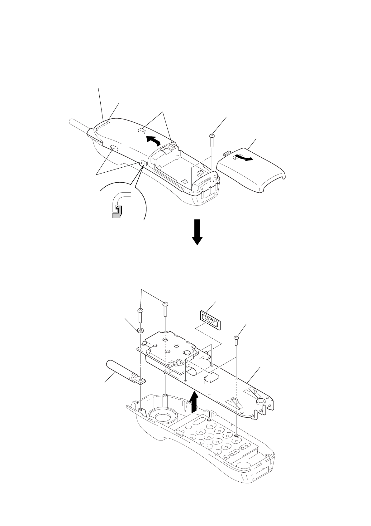
DISASSEMBLY
Note: Follow the disassembly procedure in the numerical order given.
HAND CABINET (REAR)
5 Remove the hand cabinet (rear)
to direction of the arrow B.
4 claw
3 two claws
B
3 two claws
2 two screws
(BTP3 × 12)
1 Remove the battery case li
to direction of the arrow A.
A
HAND MAIN BOARD
4 antenna (ANT2)
3 washer
2 two screws
(BTP3 × 10)
6 vol knob
1 four screws
(P2 × 5)
5 Remove the hand main board
to direction of the arrow C.
C
– 11 –
Page 12

CABINET BASE (BOTTOM)
3 cabinet base
(bottom)
2 claw
2 claw
1 five screws
(BTP3 × 12)
BASE MAIN BOARD, BASE KEY BOARD
3 screw (P3 × 10)
4 harness
6 tone-pulse
knob
5 base main board
1 three screws
(P3 × 8)
2 three charge springs
7 seven screws
(P3 × 10)
8 base key board
– 12 –
Page 13

SECTION 3
TEST MODE
BASE UNIT
1. Entering the Test Mode
1. While pressing the [HANDSET LOCATOR] key, turn the
power ON, then change over the
“PULSE” to “TONE” within 4 seconds.
2. When enter the test mode, Light up the
[DIAL MODE] switch from
[CHARGE] and
[IN USE] LEDs.
2. Change the Mode
Press and hold the [HANDSET LOCATOR] key for about 2 seconds to change the mode like Mode 1, Mode 2, Mode 3, Mode 4,
Mode 1....
Mode 1:
[CHARGE] LED : Lights up.
Function : Change the channel.
Operation : Each time the [HANDSET LOCATOR] key
is pressed momentarily, change the channel
like 0, 1, 2...9, 0... (default channel is 5ch)
Mode 2:
[CHARGE] LED : Goes off.
Function : Toggle TX power.
Operation : Each time the [HANDSET LOCATOR] key
is pressed momentarily, change over ON/
OFF. (default status is ON)
Mode 3:
[CHARGE] LED : Lights up.
Function : Not used in servicing.
HANDSET
1. Entering the Test Mode
1. Press two keys of [3] and [#] simultaneously.
2. When enter the test mode, the happy tone is emitted.
2. Key Functions
[CHANNEL] key
• Change the channel. (Each time the [CHANNEL] key is
pressed, change the channel like 0, 1, 2...9, 0... (default channel is 5))
• Refresh PLL, RX/TX counters.
[PGM] key
• Toggle TX power. (ON: lights up the [TALK/BATT LOW]
LED)
• Refresh PLL, TX counters.
[SPEED DIAL] key
• Toggle RX power.
• Refresh PLL REF, RX/TX counters.
[REDIAL] key
• Toggle TX attenuator.
• Refresh PLL status register.
[TALK] key
• Change PLL gain mode. (lowest → highest (4 steps))
[OFF] key
• Exit the test mode and emit the sad tone.
Mode 4:
[CHARGE] LED : Goes off.
Function : Transmit the tone signal for 3 seconds.
Operation : Press the [HANDSET LOCATOR] key mo-
mentarily to transmit the tone signal, and
blinks the [CHARGE] LED.
Each time transmit it, then change the frequency of signal tone like 697 Hz, 770 Hz,
852 Hz, 941 Hz, 1209 Hz, 1336 Hz, 1477
Hz, 1633 Hz, 697 Hz... (default frequency is
697 Hz)
3. Releasing the Test Mode
Disconnect the power.
Note: All keys pressed will emit the key tone.
– 13 –
Page 14

SECTION 4
ELECTRICAL ADJUSTMENTS
0 dBm = 0.775 V
0 dBv = 1 V
BASE UNIT
Adjustment Equipment and Connection
BASE RF Unit
RF
generator
audio
generator
feedback
bridge
Setting:
1. Enter the test mode. (refer to page 13)
2. Set the channel to 6ch.
TP (ANT)
BASE MAIN
Board
LINE Jack (J7)
TP14 (TX LOOP VOLTAGE)
TP15 (RX LOOP VOLTAGE)
DC 9 V
5. MOD Deviation Adjustment
1. Connect the RF generator to TP (ANT) on the MAIN RF unit.
2. Connect the audio generator (to feedback bridge) to LINE jack
(J7) on the BASE MAIN board.
3. Set the audio generator as follows.
output level : –17 dBv
output frequency: 1 kHz
4. Set the RF generator as follows.
input frequency : 903.8 MHz
filter frequency : 300 Hz to 3 kHz
detector : PK+1/2
5. Adjust VR2 on the B ASE MAIN board for 25 ± 3 kHz reading
on the RF generator.
digital
voltmeter
1. RX Loop Voltage Confirmation
1. Connect the digital v oltmeter to TP15 (RX LOOP V OLT A GE)
on the BASE MAIN board.
2. Confirm that the value of digital voltmeter is 0.5 Vdc to 4.3
Vdc.
2. TX Loop Voltage Confirmation
1. Connect the digital v oltmeter to TP14 (TX LOOP V OLT A GE)
on the BASE MAIN board.
2. Confirm that the value of digital voltmeter is 0.5 Vdc to 4.3
Vdc.
3. TX Frequency Adjustment
1. Connect the RF generator to TP (ANT) on the BASE RF unit.
2. Adjust C15 on the BASE MAIN board for 903.8 MHz ± 3
kHz reading on the RF generator.
4. DEMOD Audio Level Adjustment
1. Connect the RF generator to TP (ANT) on the BASE RF unit.
2. Connect the audio generator (to feedback bridge) to LINE jack
(J7) on the BASE MAIN board.
3. Set the RF generator as follows.
output frequency : 926.55 MHz
output level : –50 dBm
FM deviation : 25 kHz
MOD tone frequency: 1 kHz
4. Adjust VR1 on the BASE MAIN board for –10 ± 1 dBv reading on the audio generator.
– 14 –
Page 15

Adjustment Location:
– BASE RF UNIT (Side A) –
TP (ANT)
– BASE MAIN BOARD (Component Side) –– BASE MAIN BOARD (Conductor Side) –
VR1
DEMOD Audio
Level Adjustment
TX Frequency Adjustment
C15
VR2
MOD Deviation
Adjustment
SW1
TONE
PULSE
TP15 (RX LOOP VOLTAGE)
TP14 (TX LOOP VOLTAGE)
– 15 –
Page 16

HANDSET
Adjustment Equipment and Connection
HAND RF Unit
RF
generator
audio
generator
Setting:
1. Enter the test mode. (refer to page 13)
2. Set the channel to 6ch.
3. Set the [VOL] switch (S19) to the “L” position.
4. Disconnect the microphone (U9) wire at the HAND MAIN
board.
1. TX Frequency Adjustment
1. Connect the RF generator to TP (ANT) on the HAND RF unit.
2. Adjust C92 on the HAND MAIN board for 926.55 MHz ± 3
kHz reading on the RF generator.
TP (ANT)
HAND MAIN
Board
TP (RECEIVER +)or
TP (MIC IN)
digital
voltmeter
DC 3.6 V
Adjustment Location:
– HAND RF UNIT –
(Side B)
TP (ANT)
– HAND MAIN BOARD –
(Side A)
2. DEMOD Audio Level Adjustment
1. Connect the RF generator to TP (ANT) on the HAND RF unit.
2. Connect the audio g enerator to TP (RECEIVER +) on the
HAND MAIN board.
3. Set the RF generator as follows.
output frequency : 903.8 MHz
output level : –50 dBm
FM deviation : 25 kHz
MOD tone frequency: 1 kHz
4. Adjust R113 on the HAND MAIN board for –90 ± 5 mV reading on the audio generator.
3. MOD Deviation Adjustment
1. Connect the RF generator to TP (ANT) on the HAND RF unit.
2. Connect the audio generator to TP (MIC IN) on the HAND
MAIN board.
3. Set the audio genera tor as follows.
output level : 35 mV
output frequency: 1 kHz
4. Adjust R119 on the HAND MAIN board for 25 ± 3 kHz reading on the RF generator.
C92
TX Frequency
Adjustment
R113
DEMOD Audio Level
Adjustment
R119
MOD Deviation
Adjustment
TP (RECEIVER +)
TP
(MIC IN)
– 16 –
Page 17

SECTION 5
DIAGRAMS
5-1. BLOCK DIAGRAM – BASE UNIT Section –
ANT1
(ANTENNA)
7 SEGMENTS
RF UNIT
EEPROM
U3
U1
LED
MESSAGE
COUNTER
RF1
PLL EN
4 7 5
RX AUDIO
TX PWR
TX AUDIO
CAR DET
PLL REF
PLL CLK
PLL DATA
3 4 2 1
DIN
DOUT
CA1
CA2
A1
A2
B1
B2
C1
C2
D1
D2
E1
E2
F1
F2
G1
G2
+5V
15
10
13
12
14
11
16
V REG B+
(RX PWR B+)
8
10 2 1 23 20 19 18
TX PWR B+
1
2 3 4 5
9
OSC
6
CLK
4
5
1
8
3
6
2
7
9
Q4
C15
FREQUENCY
11
EEP/PLL DATA
12
EEP DI
13
EEP/PLL CLK
10
PLL EN
EEP CS
9
CS
BUFFER
U5 (3/4)
LOW-PASS
U5 (4/4)
X1
TX
4MHz
26
27 18 25 16
OSC2
OSC1
CAR-DET
FILTER
TX MUTE
RX DATA
Q6
COMPRESSOR, EXPANDER,
MUTE
15
QA
1
QB
2
QC
4
QD
3
QE
5
QF
6
QG
NOISE GATE
U4
FIL2
IN
LOW-PASS
FILTER
FIL1
OUT
LOW-PASS
FILTER
LED/7 SEGMENTS
FIL2
OUT
FIL1
IN
SYSTEM CONTROLLER
U1 (1/2)
7 SEGMENTS
LED DRIVE
Q9
7 SEGMENTS
LED DRIVE
Q8
LED DRIVER
U10
LATCH CLK
SHIFT CLK
RESET
14
A
12
11
10
DE-
EMPHASIS
DATA/AUDIO
ADDER
U5 (2/4)
J4
9
10
15
14
13
2
MOD
DEVIATION
7SEG D1
7SEG D2
L DATA
L CLK
L LATCH
+3V
VR2
PRE
NF
PREAMP
+
24
DTMF1 – DTMF6
TX DATA
EXPANDER
CIRCUIT
PRE
EMPHASIS
3 – 8
I-TAD
UNIT
EXP
OUT
COMP
OUT
DTMF
LOW-PASS FILTER
U5 (1/4)
I-TAD RING DET
LIFPOUT
MIC +
MIC –
LIFMIN1
SPK OUT
SP EN
HOOK SW
BU HOOK
LINE DC
+5V
OFF HOOK
RINGER DET
VR1
DEMOD
AUDIO LEVEL
EXP
J1
10
17
16
11
18
4
1
5
3
8
14
17
20
COMPRESSOR
MUTE
CIRCUIT
COMP
+
IN2
6 15 16
MUTE
+
V REG B+
RIN RO1
MIC
OUT
9
RO1 AMP
MIC AMP
SPEAKER AMP
U6
HOOK ON/OFF
DETECT
Q1
MIC
SPP-A941
T1
LINE
TRANSFORMER
BUFFER
Q17
NF
10
MI1
MIC
SP1
(SPEAKER)
D3
U7
HOOK ON/OFF
RELAY DRIVE
Q7
COMPARATOR
LINE DC
U2
D9 – 12
LED1
IN USE
LED DRIVE
Q12
RINGER
DETECT
U8
+
J7
LINE
• SIGNAL PATH
: RX
: TX
: BELL
05
LD4 LD3 LD2 LD1
Ref No.
KP0
KP1
KP2
KP10
KP11
KP12
KP20
23
PANEL DESIGNATION
REC/MEMO
ERASE
ANSWER ON/OFF
MAIL BOX 1
2
3
SLOW REPEAT
MAIL BOX
1
Ref No.
KP22
KP30
KP31
KP40
KP41
KP42
ANSWER
ON/OFF
PANEL DESIGNATION
QUICK SKIP
VOLUME –
VOLUME +
MENU
SELECT
TIME SET
– 17 – – 18 –
B+ SWITCH
(FOR LEDS)
G10
KEY MATRIX
KP0 – 2, 10 – 12, 20, 22,
KP30, 31, 40 – 42
11
16
20
3
5
LED SEL
COL0
COL2
ROW0
ROW4
SW1
DIAL MODE
PULSE
TONE
KP16
HANDSET
LOCATOR
TONE/
PULSE
SYSTEM CONTROLLER
U1 (2/2)
21
PAGE
ATE
CRADLE DET
TX ENABLE
RESET
2322
19
LED2
CHARGE
15
1
CRADLE/CHARGE
DETECT
Q15, 16
TX PWR B+
B+ SWITCH
(FOR TX SYSTEM)
Q5
RESET SIGNAL
GENERATOR
Q2, 3
V REG B+
(RX PWR B+)
+5V
REGULATOR
U9
ATE
CHARGE
+
TERMINAL
–
J8
+
–
DC IN 9V
Page 18

SPP-A941
5-2. BLOCK DIAGRAM – HANDSET Section –
ANT2
(ANTENNA)
RX AUDIO
RF2
RF UNIT
RX PWR
TX PWR
TX AUDIO
PLL DATA
PLL CLK
PLL EN
PLL REF
1
7
9
8
5
3
4
6
RX PWR B+
TX PWR B+
OSC
Q12
BUFFER
U5 (4/4)
FREQUENCY
C92
TX
LOW-PASS
FILTER
U5 (2/4)
BUFFER
Q1
X1
4MHz
S19
VOL
COMPRESSOR, EXPANDER,
NOISE GATE
U7
FIL2
IN
2 1 23 20 19 17
FIL1
OUT
3 4 5
25
RX DATA
11
PLL DATA
13
PLL CLK
12
PLL EN
26
OSC2
OSC1
TALK/BATT LED
SYSTEM
CONTROLLER
27
LOW-PASS
FILTER
LOW-PASS
FILTER
TX DATA
U3
MUTE
BEEP
FIL2
OUT
FIL1
PRE
DE-
EMPHASIS
24
19
20
17
DATA/AUDIO
ADDER
U5 (3/4)
IN
IN
R119
MOD
DEVIATION
TALK/BATT LOW
PREAMP
EXPANDER
CIRCUIT
+
BUZZER DRIVE
Q14, 17
D5
PRE
EMPHASIS
EXP
OUT
R113
DEMOD
AUDIO LEVEL
COMP
OUT
ROIN RO2
RO1 AMP RO2 AMP
EXP
MUTE
15
COMPRESSOR
CIRCUIT
COMP
+
IN2
6 16
MUTE
M (MEDIUM)
18
RO1
MIC AMP
L (LOW)
H (HIGH)
MIC
NF
U8
(SPEAKER)
10
U9
(MIC)
U4
(BUZZER)
• SIGNAL PATH
05
Ref No.
S1
S2
S3
S4
S5
S6
S7
S8
S9
S10
S11
S12
S13
S14
S15
S16
S17
S18
: RX
: TX
: BELL
PANEL DESIGNATION
FLASH TALK
CHANNEL
OFF
1
2 ABC
3 DEF
4 GHI
5 JKL
6 MNO
7 PQRS
8 TUV
9 WXYZ
TONE
0 OPER
#
PGM
SPEED DIAL
REDIAL
KEY MATRIX
(SHEET KEY)
S1 – 18
21
ATE
7 – 10
3 – 6
ROW1–ROW4
COL0– COL3
CRADLE DET
TX ENABLE
RX ENABLE
LOW BATT
IRQ
RESET
23
RESET SIGNAL GENERATOR, BATTERY DETECT
MCU PWR B+
B+ SWITCH
V-ANA PWR B+
15
TX PWR B+
RX PWR B+
16
Q20
WATCH DOG TIMER
2
1
22
COMPARATOR
(FOR ANALOG SYSTEM)
U5 (1/4)
Q18
B+ SWITCH
(FOR TX SYSTEM)
Q13
B+ SWITCH
(FOR RX SYSTEM)
Q16
SWITCHING
Q19
3
14
6
10
OUTPUT
FEED
BACK
ERROR
COMP OUT
REGULATOR,
ERROR
AMP
MUTE
DETECT AMP
AUXILLARY
COMPARATOR
U11
REGULATOR
SHUT DOWN
COMPARATOR
DROP OUT
1.23V
INPUT
SHUT
DOWN
COMP IN
CRADLE
DETECT
Q15
15
5
11
D7
ATE
+
–
RECHARGEABLE
BATTERY PACK
(BP-T23)
CHARGE
TERMINAL
– 19 –
– 20 –
Page 19

5-3. NOTE FOR PRINTED WIRING BOARDS AND SCHEMATIC DIAGRAMS
Note on Printed Wiring Board:
• X : parts extracted from the component side.
• Y : parts extracted from the conductor side.
• b : Pattern from the side which enables seeing.
(The other layers' patterns are not indicated.)
• : connected by carbon pattern.
Caution:
Pattern face side: Parts on the pattern face side seen from
(Side B) the pattern face are indicated.
Parts face side: Parts on the parts face side seen from
(Side A) the parts face are indicated.
Note on Schematic Diagram:
• All capacitors are in µF unless otherwise noted. pF: µµF
50 WV or less are not indicated except for electrolytics
and tantalums.
• All resistors are in Ω and 1/
specified.
4
W or less unless otherwise
• % : indicates tolerance.
• C : panel designation.
• U : B+ Line.
• H : adjustment for repair.
• Power voltages are dc 9 V and f ed with regulated dc power
supply from external power voltage jack (J8) on the BASE
MAIN board, dc 12 V and fed with regulated dc power
supply from modular jack (J7) on the BASE MAIN board
with 100 Ω in series, and dc 3.6 V and f ed with regulated
dc power supply from battery terminal on the HAND MAIN
board.
• Voltages and w av eforms are dc with respect to ground in
test mode.
: Impossible to measure
∗
• Voltages are tak en with a V OM (Input impedance 10 MΩ).
Voltage variations may be noted due to normal production tolerances.
• Waveforms are taken with a oscilloscope.
Voltage variations may be noted due to normal production tolerances.
• Circled numbers refer to waveforms.
• Signal path.
N : RX
O : TX
P : BELL
• IC Block Diagrams
U6 KA8602D (BASE MAIN Board)
RIPPLE
8
REJECTION
7
MUTE
+–
6
OUT2
5
GND
IN+
IN–
OUT1
VCC
BIAS
CIRCUIT
1
2
+–
AMP1 AMP2
3
4
U4 TA31103F (BASE MAIN Board)
U7 TA31103F (HAND MAIN Board)
VCC
PRE NF
24
23
PRE AMP
VREF
FILTER
AMP 2
PRE OUT
E-RECT
22
21
–
+
+
–
FILTER
AMP 1
∆G
THROUGH
IN 2
AMP
+
–
+
–
EXP
MUTE
VREF
VREF
SUM
AMP
–
+
COMP
MUTE
EXP OUT
20
19
VREF
THROUG
RIN
RO1
–
+
RO1
AMP
SUM
AMP
VREF
+
–
VREF
–
+
RO2
AMP
COMP MUTE
THROUG
EXP MUTE
RO2
1718151413
16
SWITCH
CONTROL
MIC AMP
+
–
VREF
∆G
1
FIL2 OUT
2
FIL2 IN
3
FIL1 OUT
4
FIL1 IN
5
COMP OUT
7
6
IN2
C-RECT
8
C-NF
9
MIC OUT
10
11
MIC IN
MIC NF
12
GND
U10 MC74HC595AF (BASE MAIN Board) U11 LP2953IM (HAND MAIN Board)
1
GND
2
NC
3
PARALLEL DATA
OUTPUT
SERIAL DATA
INPUT
OUTPUT
16 15 14 13 12
VCC
QA
ENABLE
A
LATCH
CLOCK
SHIFT
CLOCK
11
SHIFT REGISTER
LATCH
QF
QE
QC
QD
QB
2 345 6 7 8
1
PARALLEL DATA
OUTPUT
SERIAL DATA
OUTPUT
RESET
10
9
SQH
QG
QH
GND
OUTPUT
SENSE
SHUT DOWN
ERROR
GND
NC
4
5
DETECTION AMP
6
7
8
DROP OUT
ERROR
AMP
+
–
+
–
SHUT DOWN
COMPARATOR
+
–
–
+
AUXILLARY
COMPARATOR
1.23V
16
15
14
13
12
11
10
9
GND
INPUT
FEEDBACK
5V TAP
VREF
COMP IN
COMP OUT
GND
– 21 –
– 22 –
Page 20

SPP-A941
5-4. PRINTED WIRING BOARD – BASE MAIN Board – • See page 21 for Note on Printed Wiring Board.
• Semiconductor
Location
Ref. No. Location
D1 B-6
D3 F-9
D4 B-12
D5 I-12
D8 B-4
D9 B-4
D10 B-4
D11 E-4
D12 C-3
D16 C-3
D25 B-7
Q1 I-10
Q2 I-6
Q3 I-6
Q4 I-10
Q5 H-9
Q6 I-4
Q7 C-6
Q8 I-14
Q9 H-14
Q10 I-14
Q12 C-11
Q15 C-12
Q16 E-12
Q17 D-6
U1 H-8
U2 C-6
U3 J-7
U4 H-3
U5 H-6
U6 I-13
U8 E-5
U9 F-4
U10 G-12
Z1 D-2
Z2 C-2
1
2 3 4 5 6 7 8 9 10 11 12 13 14
15
BASE MAIN BOARD
A
D8
B
F1
L26
U7
D12
L28
C135
R59
R60 C28
C26
R62
R61
TRANSFORMER
D11
R26 C27
C
J7
LINE
6
4
2
1
3
D
J8
+
–
DC IN 9V
5
E
Z2
Z1
D16
KA
C131
R138
L25
L27
L4
F
VR1
G
R55
C20
R56
C21
R57
H
EC1
+
C19 R54
C34 C17
R75
C32
R76
C35
05
C18
R53
C16
R74
C33
I
J
EC2
C25
+
EC3
EC6
+
+
C23
R52
13
12
U4
24
1
VR2
LINE
U9
3
1
Q6
E C B
R58 C22
D10
R111
C59
EC132
+
U8
2
1
C136
C52
R85
C39
R91
R89
C41
R90
R77
C38
R86
C40
R92
C50
C14
R50
R49
C13
R48
C12 C53
R47
C36
C37 R66
K
D9
EC150
+
+
EC134
+
C150
R2
R3
BCE
Q7
R7
C56
R110
EC137
5
8
R121
R132
3
4
R122
R141
Q4
BCE
R149
U2
Q17
C2
4
1
R142
R139
EC133
+
C15
C6
C7
R72
R95
R93
C57
8
U5
14
R46
Q3
R30
B C E
R22
R23
Q2
B C E
R67
C30
7
R68
C29
1
R24
C31
R73
R84
R64
C5
R65
D25
AA
D1
R5
R109
R4
R6
C4
R8
R9
C1
R143
R83
R15
C55
L2
X1
R105
R27
C9
L3
D3
R63
K
A
K
R69
EC4
R32
EC11
EC5
+
+
R20
18
+
EC10
RF1
UNIT
E C B
RF
ANT1
+
R21
13
1
J2
B C E
J1
Q1
C51
1
SW1
TONE PULSE
SW1
DIAL MODE
C10
C8
R39
R44
R38
R43
R37
R42
R36
R41
R34
R40
R35
R45
C11
5
U3
8
1
14
4
1
28
TP15(RX LOOP VOLTAGE)
R82
TP14 (TX LOOP VOLTAGE)
Q5
U1
15
R29
R25
R33
B C E
R96
Q4
R31
C99
R104
R79
R51
D4
K A K
R71
Q12
B C E
R70
R81
R16 R80
C48
C45
R19
D5
AK
R108
Q15
B C E
R78
Q16
E C B
8
1
C44 R101
U6
R28
R17
R14
R13
R12
R11
R10
C42
4
1
C54
EC8
+
U10
9
16
R102
C3
5
8
C43
R100
EC9
+
C97
L21
C46
L1
C95
L23
MI1
MIC
J3
27
22
R1
R106
R107
R98
J4
R103
R99
R97
E C B
E C B
E C B
Q9
Q10
Q8
1
1
35-4672-04
I-TAD
UNIT
+
ATE
–
A
BASE KEY
BOARD
J2
(Page 28)
00
CHARGE
TERMINAL
– 23 –
– 24 –
Page 21

5-5. SCHEMATIC DIAGRAM – BASE MAIN Board – • See page 27 for Waveform. • See page 22 for IC Block Diagrams. • See page 21 for Note on Schematic Diagram.
SPP-A941
– 25 –
(Page 29)
– 26 –
Page 22

SPP-A941
5-6. PRINTED WIRING BO ARD – BASE KEY Boar d – • See page 21 for Note on Printed Wiring Board.
• Waveforms
– BASE MAIN Board –
1 U1 wh (OSC2)
2 V/DIV, 100 ns/DIV
250 ns
4.5 Vp-p
– HAND MAIN Board –
2 U3 wh (OSC2)
2 V/DIV, 100 ns/DIV
250 ns
4 Vp-p
1 2 3 4 5 6
BASE KEY BOARD
BLK
RED
SP1
A
KP0
REC/MEMO
VOLUME
KP2, LD1
ANSWER
ON/OFF
KP2
LD1
KP31
B
KP1
C
D
ERASE
KP42
TIME/SET
16 9
U1
(MESSAGE COUNTER)
1
KP41
SELECT
KP40
MENU
8
– +
KP30
• Semiconductor
Location
Ref. No. Location
LD1 C-6
LD2 H-5
LD3 G-5
LD4 F-5
LED1 I-2
LED2 H-2
U1 C-4
E
KP12, LD4
KP12
3
LD4
F
KP20
SLOW
REPEAT
KP11
KP11, LD3
2
LD3
KP22
QUICK
SKIP
G
KP10, LD2
KP10
H
LED2
CHARGE
I
27
LED1
IN USE
J
05
(Page 24)
BASE MAIN
BOARD
A
J3
MAIL BOX
1
LD2
KP16
HANDSET
LOCATOR
1
1-676-810-
11
– 27 –
– 28 –
Page 23

5-7. SCHEMATIC DIAGRAM – BASE KEY Board – • See page 21 for Note on Schematic Diagram.
SPP-A941
(Page 26)
– 29 –
Page 24

SPP-A941
5-8. PRINTED WIRING BOARD – HAND MAIN Board – • See page 21 for Note on Printed Wiring Board.
12 34 5 6 78
A
HAND MAIN BOARD
B
U8
RED
BLK
C139
R76
C
R129
C132
Q12
C93
R75
C92
C91C75
D
E
F
RECHARGEABLE
BATTERY PACK
(BP-T23)
G
3.6V 600mAh
R96
C102
R23
+
Q19
B
R97
B
EC
Q1
R143
K/A
D8
C118
A
K
+
R98
C100
D14
H
(SIDE A)
Q16
Q13
R77
ECB
C106
C105
R110
C131
R131
C130
C124
C128
C127
R123
R125
R130
+
E
C
C126
R124
R74
B
28 15
X1
C123
C40
R36R140
Q20
B
EC
EC
1
R135
R1
R24
R65
R105
C101
C125
R106
R107
R91
78
R89
1
R83
U11
R99
C3
R84
89
TP ( RECEIVER + )
Q15
B
EC
D7
K
R82
R81
K/A
A
K
A
K
U4
RED
BLK
C103
C95
C108
ECB
1
12 13
C110
+
C119
C104
R108
U5
16
TP ( MIC IN )
K
D6
A
+
R109
HAND MAIN BOARD
(SIDE B)
D5
TALK/BATT LOW
R3
R4
R116
R78
R111
R138
24
C111
R112
U7
C99
U3
R63
R49
14
C134
R87
R88
R90
C97
+
C112
C113
C2
R115
C116
R80
R42
C107
C114
R114
R113
141
R69
R70
R141
C140
R144
C138
R145
R119
B
R122
U9
R146
R102
R133
R121
C121
R94
C129
R142
R100
R103
C109
R139
E
B
C
Q17
35-4393-03-
R134
R147
R128
R127
R85
R86
E
C
R95
Q14
Q18
B
EC
+
C122
BLK
RED
00
H
M
L
S19
110
VOL
S1
FLASH
TALK
S4
1
S7
4 GHI
S10
7 PQRS
S13
TONE
S16
PGM
ANT2
RF2
RF
UNIT
S3
OFF CHANNEL
S5
2 ABC
S8
5 JKL
S11
8 TUV
S14
0 OPER
S17
SPEED DIAL
35-4393-03-
S2
3 DEF
S9
6 MNO
S12
9 WXYZ
S15
S18
REDIAL
S6
00
I
+
ATE
CHARGE TERMINAL
–
• Semiconductor Location
Ref. No. LocationRef. No. Location
D5 B-4
D6 H-3
D7 H-3
D8 F-2
D14 H-2
Q1 E-2
Q12 D-2
Q13 C-3
Q14 G-4
Q15 G-2
Q16 C-3
Q17 F-4
Q18 G-3
Q19 E-2
Q20 E-3
U3 D-3
U5 E-3
U7 C-3
U11 F-3
– 30 –
Page 25

5-9. SCHEMATIC DIAGRAM – HAND MAIN Board – • See page 27 for Waveform. • See page 22 for IC Block Diagrams. • See page 21 for Note on Schematic Diagram.
SPP-A941
– 31 – – 32 –
Page 26

5-10. IC PIN FUNCTION DESCRIPTION
• BASE MAIN BOARD U1 LSC527737DW-A94100FB (SYSTEM CONTROLLER)
• HAND MAIN BOARD U3 LSC526609DW (SYSTEM CONTROLLER)
Pin No. Pin Name I/O Description
1 RESET I
2 IRQ I Interrupt request signal input terminal Not used (fixed at “H”)
3 to 8
9 EEP CS O Chip select signal output to the EEPROM (U3) “L”: un-select, “H”: select
10 PLL EN O
11 EEP/PLL DATA O Serial data output to the EEPROM (U3) and RF unit (RF1)
12 EEP DI I Serial data input from the EEPROM (U3)
13 EEP/PLL CLK O Serial data transfer clock signal output to the EEPROM (U3) and RF unit (RF1)
14 VSS — Ground terminal
15 TX ENABLE O TX system power supply on/off control signal output “L”: TX system power on
16 MUTE O
17 OFF HOOK O Hook on/off control signal output terminal “L”: off hook, “H”: on hook
18 CAR-DET I Carrier detect signal input from the RF unit (RF1) “L”: signal, “H”: no signal
19 CRADLE DET I Detect signal input of the handset unit on cradle or off cradle “L”: on cradle, “H”: off cradle
20 RINGER DET I Detect signal input of the ringer coming “L”: ringer is detected
21 PAGE I HANDSET LOCATOR switch (KP16) input terminal “L” is input when key pressing
22 TONE/PULSE I DIAL MODE select switch (SW1) input terminal “L”: pulse, “H”: tone
23 ATE I/O Communication in/out terminal with ATE program
24 TX DATA O Transmit data output terminal
25 RX DATA I Receive data input terminal
26 OSC2 O Main system clock output terminal (4 MHz)
27 OSC1 I Main system clock input terminal (4 MHz)
28 VDD — Power supply terminal (+5V)
DTMF1 to
DTMF6
System reset signal input from the reset signal generator (Q2, 3) “L”: reset
For several hundreds msec. after the power supply rises, “L” is input, then it changes to “H”
O DTMF signal output terminal
Chip enable signal output to the RF unit (RF1)
When PLL EN goes from “L” to “H”, it load data from PLL DATA
RX and TX muting control signal output to the TA31103F (U4) “L”: muting on
RX mode: After receiving premble bits from handset muting it until data sent finished
TX mode: During sending data to handset, muting it
Pin No. Pin Name I/O Description
1 RESET I
2 IRQ I Interrupt request signal input terminal
3 to 6 COL3 to COL0 O Key scan signal output to the key matrix
7 to 10 ROW4 to ROW1 I Key scan signal input from the key matrix
11 PLL DATA O Serial data output to the RF unit (RF2)
12 PLL EN O
13 PLL CLK O Serial data transfer clock signal output to the RF unit (RF2)
14 VSS — Ground terminal
15 TX ENABLE O TX system power supply on/off control signal output “L”: TX system power on
16 RX ENABLE O RX system power supply on/off control signal output “L”: RX system power on
17
18 LIGHT LED O LED drive signal output of the key back light Not used (open)
19 MUTE O
20 BEEP O Buzzer sound drive signal output terminal
21 ATE I/O Communication in/out terminal with ATE program
22 LOW BATT I Battery level detect signal input from the LP2953IM (U11)
23 CRADLE DET I Detect signal input of the handset unit on cradle or off cradle “L”: on cradle, “H”: off cradle
24 TX DATA O Transmit data output terminal
25 RX DATA I Receive data input terminal
26 OSC2 O Main system clock output terminal (4 MHz)
27 OSC1 I Main system clock input terminal (4 MHz)
28 VDD — Power supply terminal (+5V)
TALK/BATT
LED
System reset signal input from the LP2953IM (U11) “L”: reset
For several hundreds msec. after the power supply rises, “L” is input, then it changes to “H”
Chip enable signal output to the RF unit (RF2)
When PLL EN goes from “L” to “H”, it load data from PLL DATA
O LED drive signal output of the TALK/BATT LOW indicator (D5) “L”: LED on
RX and TX muting control signal output to the TA31103F (U7) “L”: muting on
RX mode: After receiving premble bits from base unit muting it until data sent finished
TX mode: During sending data to base unit, muting it
– 33 –
– 34 –
Page 27

SECTION 6
5
EXPLODED VIEWS
NOTE:
• -XX and -X mean standardized parts, so they
may have some difference from the original
one.
• Color Indication of Appearance Parts
Example:
KNOB, BALANCE (WHITE) . . . (RED)
↑↑
Parts Color Cabinet's Color
(1) HANDSET SECTION
4
3
• Items marked “*” are not stocked since they
are seldom required for routine service. Some
delay should be anticipated when ordering
these items.
• The mechanical parts with no reference number in the exploded views are not supplied.
• Hardware (# mark) list and accessories and
packing materials are given in the last of the
electrical parts list.
5
U8
6
#2
#1
#2
7
#4
ANT2
2
11
1
Ref. No. Part No. Description Remark
1 3-036-130-01 PANEL (HS)
2 3-036-122-01 FRONT (HS), CABINET
3 3-012-611-01 SHEET (RECEIVER)
4 3-371-005-01 GASKET (RECEIVER) (TWN)
* 5 A-3672-725-A RF UNIT (HS)
#3
U9
15
16
9
U4
10
8
14
Ref. No. Part No. Description Remark
10 3-036-642-01 BUZZER, HOLDER
11 1-771-715-11 SWITCH, RUBBER KEY
14 3-036-126-01 TERMINAL (HANDSET), CHARGE
15 3-036-647-01 SPRING, BATTERY
16 3-036-646-01 HOLDER (MIC)
#
6 3-036-120-01 KNOB, VOL
7 3-036-123-01 CABINET (REAR (HS))
8 3-036-121-01 LID, BATTERY CASE
* 9 A-3672-726-A HAND MAIN BOARD, COMPLETE
ANT2 1-501-951-31 ANTENNA
U4 1-544-603-11 BUZZER
U8 1-505-593-11 SPEAKER (2.8cm)
U9 1-542-260-31 MICROPHONE, ELECTRET CONDENSER
– 35 –
Page 28

(2) BASESET SECTION
d
56
53
54
55
58
57
zA
not
supplied
59
SP1
ANT1
(including zA)
60
#6
not supplie
61
#6
52
#9
51
Ref. No. Part No. Description Remark
51 3-041-534-01 FOOT, RUBBER
52 3-042-404-01 BASE (BOTTOM), CABINET
* 53 1-676-810-11 BASE KEY BOARD
54 3-042-412-01 RUBBER, KEY
55 3-042-405-01 KEY, BASE
64
#6
MI1
63
#7
67
#8
Ref. No. Part No. Description Remark
* 61 A-3672-914-A RF UNIT (BASE)
* 63 A-3673-087-A BASE MAIN BOARD, COMPLETE
* 64 A-3673-088-A I-TAD UNIT (BASE)
65 3-023-846-01 KNOB, TONE-PULSE
66 3-042-407-01 SPRING, CHARGE
66
#7
65
56 3-042-403-01 BASE (TOP), CABINET
57 3-042-406-01 LENS (LED) (BASE)
58 3-036-127-01 HOOK
* 59 3-042-428-01 CUSHION, MIC
60 3-041-275-01 PACKING, SP
* 67 3-042-428-01 CUSHION, MIC
ANT1 1-501-999-21 ANTENNA
SP1 1-544-035-11 SPEAKER (5cm)
MI1 1-542-260-31 MICROPHONE, ELECTRET CONDENSER (MIC)
– 36 –
Page 29

SECTION 7
ELECTRICAL PARTS LIST
BASE KEY
BASE MAIN
NOTE:
• Due to standardization, replacements in the
parts list may be different from the parts specified in the diagrams or the components used
on the set.
• -XX and -X mean standardized parts, so they
may have some difference from the original
one.
• RESISTORS
All resistors are in ohms.
METAL: Metal-film resistor.
METAL OXIDE: Metal oxide-film resistor.
F: nonflammable
• Abbreviation
CND: Canadian model
Ref. No. Part No. Description Remark Ref. No. Part No. Description Remark
* 1-676-810-11 BASE KEY BOARD
***************
< LED >
LED1 8-719-052-06 LED SLR-342MGT32 (IN USE)
LED2 8-719-059-40 LED SLR-342VR3F (CHARGE)
LD1 8-719-059-40 LED SLR-342VR3F (ANSWER ON/OFF)
LD2 8-719-059-40 LED SLR-342VR3F (MAIL BOX 1)
LD3 8-719-059-40 LED SLR-342VR3F (2)
• Items marked “*” are not stocked since they
are seldom required for routine service.
Some delay should be anticipated when ordering these items.
• SEMICONDUCTORS
In each case, u: µ, for example:
uA. . : µA. . uPA. . : µPA. .
uPB. . : µPB. . uPC. . : µPC. .
uPD. . : µPD. .
• CAPACITORS
uF: µF
• COILS
uH: µH
C28 1-162-968-11 CERAMIC CHIP 0.0047uF 10% 50V
C29 1-165-128-11 CERAMIC CHIP 0.22uF 16V
C30 1-162-923-11 CERAMIC CHIP 47PF 5% 50V
C31 1-164-230-11 CERAMIC CHIP 220PF 5% 50V
C32 1-162-921-11 CERAMIC CHIP 33PF 5% 50V
C33 1-164-739-11 CERAMIC CHIP 560PF 5% 50V
C34 1-162-921-11 CERAMIC CHIP 33PF 5% 50V
C35 1-164-230-11 CERAMIC CHIP 220PF 5% 50V
C36 1-162-964-11 CERAMIC CHIP 0.001uF 10% 50V
The components identified by
mark 0 or dotted line with mark
0 are critical for safety.
Replace only with part number
specified.
When indicating parts by reference
number, please include the board.
LD4 8-719-059-40 LED SLR-342VR3F (3)
U1 8-719-803-22 LED TLR322 (MESSAGE COUNTER)
**************************************************************
* A-3673-087-A BASE MAIN BOARD, COMPLETE
**************************
< CAPACITOR/RESISTOR >
C1 1-164-156-11 CERAMIC CHIP 0.1uF 25V
C2 1-162-967-11 CERAMIC CHIP 0.0033uF 10% 25V
C3 1-107-826-11 CERAMIC CHIP 0.1uF 10% 16V
C4 1-162-967-11 CERAMIC CHIP 0.0033uF 10% 25V
C5 1-107-826-11 CERAMIC CHIP 0.1uF 10% 16V
C6 1-162-919-11 CERAMIC CHIP 22PF 5% 50V
C7 1-162-917-11 CERAMIC CHIP 15PF 5% 50V
C8 1-107-826-11 CERAMIC CHIP 0.1uF 10% 16V
C9 1-162-913-11 CERAMIC CHIP 8PF 0.5PF 50V
C10 1-164-156-11 CERAMIC CHIP 0.1uF 25V
C11 1-107-826-11 CERAMIC CHIP 0.1uF 10% 16V
C12 1-162-970-11 CERAMIC CHIP 0.01uF 10% 25V
C13 1-162-970-11 CERAMIC CHIP 0.01uF 10% 25V
C14 1-162-963-11 CERAMIC CHIP 680PF 10% 50V
C15 1-141-374-11 CAP, TRIMMER 20PF
C16 1-165-128-11 CERAMIC CHIP 0.22uF 16V
C17 1-164-739-11 CERAMIC CHIP 560PF 5% 50V
C18 1-162-968-11 CERAMIC CHIP 0.0047uF 10% 50V
C19 1-162-968-11 CERAMIC CHIP 0.0047uF 10% 50V
C20 1-162-970-11 CERAMIC CHIP 0.01uF 10% 25V
C21 1-162-964-11 CERAMIC CHIP 0.001uF 10% 50V
C22 1-162-968-11 CERAMIC CHIP 0.0047uF 10% 50V
C23 1-164-227-11 CERAMIC CHIP 0.022uF 10% 25V
C24 1-164-227-11 CERAMIC CHIP 0.022uF 10% 25V
C25 1-107-826-11 CERAMIC CHIP 0.1uF 10% 16V
C26 1-162-966-11 CERAMIC CHIP 0.0022uF 10% 50V
C27 1-162-968-11 CERAMIC CHIP 0.0047uF 10% 50V
C37 1-162-968-11 CERAMIC CHIP 0.0047uF 10% 50V
C38 1-162-909-11 CERAMIC CHIP 4PF 0.25PF 50V
C39 1-107-826-11 CERAMIC CHIP 0.1uF 10% 16V
C40 1-165-176-11 CERAMIC CHIP 0.047uF 10% 16V
C41 1-162-977-11 CERAMIC CHIP 0.0018uF 10% 50V
C42 1-162-967-11 CERAMIC CHIP 0.0033uF 10% 50V
C43 1-216-864-11 METAL CHIP 0 5% 1/16W
C44 1-107-826-11 CERAMIC CHIP 0.1uF 10% 16V
C45 1-107-826-11 CERAMIC CHIP 0.1uF 10% 16V
C46 1-162-927-00 CERAMIC CHIP 100PF 5% 50V
C48 1-110-563-11 CERAMIC CHIP 0.068uF 10% 16V
C50 1-107-826-11 CERAMIC CHIP 0.1uF 10% 16V
C51 1-162-927-00 CERAMIC CHIP 100PF 5% 50V
C52 1-107-826-11 CERAMIC CHIP 0.1uF 10% 16V
C53 1-107-826-11 CERAMIC CHIP 0.1uF 10% 16V
C54 1-125-837-11 CERAMIC CHIP 1uF 10% 6.3V
C55 1-162-964-11 CERAMIC CHIP 0.001uF 10% 50V
C56 1-162-964-11 CERAMIC CHIP 0.001uF 10% 50V
C57 1-107-826-11 CERAMIC CHIP 0.1uF 10% 16V
C59 1-104-570-11 CERAMIC 0.001uF 10% 2KV
C95 1-216-864-11 METAL CHIP 0 5% 1/16W
C97 1-164-227-11 CERAMIC CHIP 0.022uF 10% 25V
C99 1-162-964-11 CERAMIC CHIP 0.001uF 10% 50V
C131 1-136-193-11 MYLAR 0.47uF 5% 250V
C135 1-164-156-11 CERAMIC CHIP 0.1uF 25V
C136 1-164-227-11 CERAMIC CHIP 0.022uF 10% 25V
C150 1-162-964-11 CERAMIC CHIP 0.001uF 10% 50V
< DIODE/VARISTOR >
D1 8-719-055-76 DIODE 1N4148
D3 8-719-820-05 DIODE 1SS181
D4 8-719-909-90 DIODE BAV99
D5 8-719-976-19 DIODE RLS-4148
D8 1-801-730-11 VARISTOR
– 37 –
Page 30

BASE MAIN
Ref. No. Part No. Description Remark
D9 8-719-911-55 DIODE U05G
D10 8-719-911-55 DIODE U05G
D11 8-719-911-55 DIODE U05G
D12 8-719-911-55 DIODE U05G
D16 8-719-976-19 DIODE RLS-4148
D25 1-801-730-11 VARISTOR
< CAPACITOR >
EC1 1-126-961-11 ELECT 2.2uF 20% 50V
EC2 1-126-204-11 ELECT 47uF 20% 16V
EC3 1-126-200-11 ELECT 10uF 20% 35V
EC4 1-126-200-11 ELECT 10uF 20% 35V
EC5 1-126-200-11 ELECT 10uF 20% 35V
EC6 1-126-961-11 ELECT 2.2uF 20% 50V
EC8 1-126-200-11 ELECT 10uF 20% 35V
EC9 1-117-681-11 ELECT 100uF 20% 16V
EC10 1-126-935-11 ELECT 470uF 20% 6.3V
EC11 1-117-681-11 ELECT 100uF 20% 16V
EC132 1-124-779-00 ELECT 10uF 20% 16V
EC133 1-124-779-00 ELECT 10uF 20% 16V
EC134 1-115-868-11 ELECT 0.22uF 20% 50V
EC137 1-104-664-11 ELECT 47uF 20% 16V
EC150 1-126-200-11 ELECT 10uF 20% 35V
< FUSE >
F1 1-533-842-11 FUSE (250mA/250V)
< JACK >
Ref. No. Part No. Description Remark
< RESISTOR >
R1 1-218-675-11 RES, CHIP 200 5% 1/16W
R2 1-216-570-11 METAL CHIP 10M 5% 1/16W
R3 1-216-570-11 METAL CHIP 10M 5% 1/16W
R4 1-219-570-11 METAL CHIP 10M 5% 1/16W
R5 1-219-570-11 METAL CHIP 10M 5% 1/16W
R6 1-242-957-11 RES, CHIP 5.6M 5% 1/16W
R7 1-242-957-11 RES, CHIP 5.6M 5% 1/16W
R8 1-216-835-11 METAL CHIP 15K 5% 1/16W
R9 1-216-839-11 METAL CHIP 33K 5% 1/16W
R10 1-218-675-11 RES, CHIP 200 5% 1/16W
R11 1-218-675-11 RES, CHIP 200 5% 1/16W
R12 1-218-675-11 RES, CHIP 200 5% 1/16W
R13 1-218-675-11 RES, CHIP 200 5% 1/16W
R14 1-218-675-11 RES, CHIP 200 5% 1/16W
R15 1-247-855-11 CARBON 10K 5% 1/4W
R16 1-216-833-11 METAL CHIP 10K 5% 1/16W
R17 1-218-675-11 RES, CHIP 200 5% 1/16W
R19 1-216-833-11 METAL CHIP 10K 5% 1/16W
R20 1-216-819-11 METAL CHIP 680 5% 1/16W
R21 1-216-839-11 METAL CHIP 33K 5% 1/16W
R22 1-216-725-11 RES, CHIP 56K 1% 1/10W
R23 1-208-806-11 RES, CHIP 10K 1% 1/10W
R24 1-216-845-11 METAL CHIP 100K 5% 1/16W
R25 1-216-845-11 METAL CHIP 100K 5% 1/16W
R26 1-216-864-11 METAL CHIP 0 5% 1/16W
R27 1-216-845-11 METAL CHIP 100K 5% 1/16W
J7 1-565-999-11 JACK, MODULAR 2P (LINE)
J8 1-580-727-11 JACK (DC IN 9V)
< COIL >
L1 1-408-117-00 INDUCTOR 10uH
L2 1-408-117-00 INDUCTOR 10uH
L3 1-408-117-00 INDUCTOR 10uH
L4 1-408-117-00 INDUCTOR 10uH
L21 1-408-117-00 INDUCTOR 10uH
L23 1-408-117-00 INDUCTOR 10uH
L25 1-408-117-00 INDUCTOR 10uH
L26 1-408-117-00 INDUCTOR 10uH
L27 1-408-117-00 INDUCTOR 10uH
L28 1-408-117-00 INDUCTOR 10uH
< TRANSISTOR >
Q1 T-941-615-31 TRANSISTOR MMBT3904LT1
Q2 T-941-615-31 TRANSISTOR MMBT3904LT1
Q3 T-941-615-31 TRANSISTOR MMBT3904LT1
Q4 T-941-615-31 TRANSISTOR MMBT3904LT1
Q5 8-729-026-07 TRANSISTOR MMBT3906LT1
Q6 8-729-026-07 TRANSISTOR MMBT3906LT1
Q7 8-729-050-37 TRANSISTOR MMBT2907A
Q8 8-729-026-07 TRANSISTOR MMBT3906LT1
Q9 8-729-026-07 TRANSISTOR MMBT3906LT1
Q10 8-729-026-07 TRANSISTOR MMBT3906LT1
Q12 8-729-026-07 TRANSISTOR MMBT3906LT1
Q15 8-729-026-07 TRANSISTOR MMBT3906LT1
Q16 T-941-615-31 TRANSISTOR MMBT3904LT1
Q17 T-941-615-31 TRANSISTOR MMBT3904LT1
R28 1-216-837-11 METAL CHIP 22K 5% 1/16W
R29 1-216-845-11 METAL CHIP 100K 5% 1/16W
R30 1-216-841-11 METAL CHIP 47K 5% 1/16W
R31 1-216-821-11 METAL CHIP 1K 5% 1/16W
R32 1-216-839-11 METAL CHIP 33K 5% 1/16W
R33 1-216-837-11 METAL CHIP 22K 5% 1/16W
R34 1-216-682-11 METAL CHIP 20K 0.5% 1/10W
R35 1-216-682-11 METAL CHIP 20K 0.5% 1/10W
R36 1-216-682-11 METAL CHIP 20K 0.5% 1/10W
R37 1-216-682-11 METAL CHIP 20K 0.5% 1/10W
R38 1-216-682-11 METAL CHIP 20K 0.5% 1/10W
R39 1-216-682-11 METAL CHIP 20K 0.5% 1/10W
R40 1-208-806-11 RES, CHIP 10K 1% 1/10W
R41 1-208-806-11 RES, CHIP 10K 1% 1/10W
R42 1-208-806-11 RES, CHIP 10K 1% 1/10W
R43 1-208-806-11 RES, CHIP 10K 1% 1/10W
R44 1-208-806-11 RES, CHIP 10K 1% 1/10W
R45 1-216-682-11 METAL CHIP 20K 0.5% 1/10W
R46 1-216-837-11 METAL CHIP 22K 5% 1/16W
R47 1-218-344-11 RES, CHIP 7.5K 5% 1/16W
R48 1-216-864-11 METAL CHIP 0 5% 1/16W
R49 1-216-834-11 METAL CHIP 12K 5% 1/16W
R50 1-216-834-11 METAL CHIP 12K 5% 1/16W
R51 1-216-841-11 METAL CHIP 47K 5% 1/16W
R52 1-216-853-11 METAL CHIP 470K 5% 1/16W
R53 1-218-345-11 RES, CHIP 9.1K 5% 1/16W
R54 1-216-845-11 METAL CHIP 100K 5% 1/16W
R55 1-216-821-11 METAL CHIP 1K 5% 1/16W
R56 1-216-850-11 METAL CHIP 270K 5% 1/16W
R57 1-216-852-11 METAL CHIP 390K 5% 1/16W
– 38 –
Page 31

BASE MAIN HAND MAIN
Ref. No. Part No. Description Remark
R58 1-216-850-11 METAL CHIP 270K 5% 1/16W
R59 1-216-837-11 METAL CHIP 22K 5% 1/16W
R60 1-218-292-11 RES, CHIP 20K 5% 1/16W
R61 1-216-853-11 METAL CHIP 470K 5% 1/16W
R62 1-216-857-11 METAL CHIP 1M 5% 1/16W
R63 1-247-847-11 CARBON 4.7K 5% 1/4W
R64 1-218-908-11 RES, CHIP 360K 5% 1/16W
R65 1-216-864-11 METAL CHIP 0 5% 1/16W
R66 1-216-823-11 METAL CHIP 1.5K 5% 1/16W
R67 1-216-853-11 METAL CHIP 470K 5% 1/16W
R68 1-216-847-11 METAL CHIP 150K 5% 1/16W
R69 1-216-833-11 METAL CHIP 10K 5% 1/16W
R70 1-216-829-11 METAL CHIP 4.7K 5% 1/16W
R71 1-216-819-11 METAL CHIP 680 5% 1/16W
R72 1-216-845-11 METAL CHIP 100K 5% 1/16W
R73 1-216-847-11 METAL CHIP 150K 5% 1/16W
R74 1-216-847-11 METAL CHIP 150K 5% 1/16W
R75 1-216-848-11 METAL CHIP 180K 5% 1/16W
R76 1-216-848-11 METAL CHIP 180K 5% 1/16W
R77 1-216-848-11 METAL CHIP 180K 5% 1/16W
R78 1-216-808-11 RES, CHIP 82 5% 1/16W
R79 1-216-833-11 METAL CHIP 10K 5% 1/16W
R80 1-216-841-11 METAL CHIP 47K 5% 1/16W
R81 1-216-831-11 METAL CHIP 6.8K 5% 1/16W
R82 1-216-841-11 METAL CHIP 47K 5% 1/16W
R83 1-216-821-11 METAL CHIP 1K 5% 1/16W
Ref. No. Part No. Description Remark
R142 1-218-702-11 METAL CHIP 2.7K 0.5% 1/16W
R143 1-218-847-11 RES, CHIP 1K 0.5% 1/16W
R149 1-216-821-11 METAL CHIP 1K 5% 1/16W
R150 1-216-809-11 RES, CHIP 100 5% 1/16W
< SWITCH >
SW1 1-571-377-11 SWITCH, SLIDE (DIAL MODE)
< TRANSFORMER >
T1 1-431-965-11 TRANSFORMER, LINE
< IC/RELAY/PHOTO COUPLER >
U1 8-759-658-48 IC LSC527737DW-A94100FB
U2 8-759-502-80 IC LM358M
U3 8-759-583-87 IC CAT93C46KI-2.5
U4 8-759-479-97 IC TA31103F
U5 8-759-912-77 IC LM324N
U6 8-759-658-47 IC KA8602D
U7 1-515-693-11 RELAY
U8 8-719-018-89 PHOTO COUPLER LTV817-C
U9 8-759-391-69 IC MC78M05CDT
U10 8-759-032-59 IC MC74HC595AF
< VARIABLE RESISTOR >
VR1 1-237-517-21 RES, ADJ 5K
VR2 1-237-517-21 RES, ADJ, CERMET 5K
R84 1-216-841-11 METAL CHIP 47K 5% 1/16W
R85 1-216-857-11 METAL CHIP 1M 5% 1/16W
R86 1-216-857-11 METAL CHIP 1M 5% 1/16W
R89 1-216-833-11 METAL CHIP 10K 5% 1/16W
R90 1-216-854-11 METAL CHIP 560K 5% 1/16W
R91 1-216-833-11 METAL CHIP 10K 5% 1/16W
R92 1-216-837-11 METAL CHIP 22K 5% 1/16W
R93 1-216-864-11 METAL CHIP 0 5% 1/16W
R95 1-220-372-11 RES, CHIP 200K 5% 1/16W
R96 1-216-821-11 METAL CHIP 1K 5% 1/16W
R97 1-216-845-11 METAL CHIP 100K 5% 1/16W
R98 1-216-833-11 METAL CHIP 10K 5% 1/16W
R99 1-216-845-11 METAL CHIP 100K 5% 1/16W
R100 1-216-831-11 METAL CHIP 6.8K 5% 1/16W
R101 1-216-836-11 METAL CHIP 18K 5% 1/16W
R102 1-216-841-11 METAL CHIP 47K 5% 1/16W
R103 1-216-833-11 METAL CHIP 10K 5% 1/16W
R104 1-216-833-11 METAL CHIP 10K 5% 1/16W
R105 1-219-570-11 METAL CHIP 10M 5% 1/16W
R106 1-216-845-11 METAL CHIP 100K 5% 1/16W
R107 1-216-833-11 METAL CHIP 10K 5% 1/16W
R108 1-249-393-11 CARBON 10 5% 1/4W
R109 1-216-821-11 METAL CHIP 1K 5% 1/16W
R110 1-216-809-11 RES, CHIP 100 5% 1/16W
R111 1-216-815-11 METAL CHIP 330 5% 1/16W
R121 1-216-818-11 METAL CHIP 560 5% 1/16W
R122 1-218-883-11 RES, CHIP 33K 0.5% 1/16W
R132 1-216-785-11 RES, CHIP 3.3K 1% 1/10W
R138 1-216-833-11 METAL CHIP 10K 5% 1/16W
R139 1-216-865-11 RES, CHIP 3K 5% 1/16W
R141 1-218-730-11 METAL CHIP 39K 0.5% 1/16W
< VIBRATOR >
X1 1-760-096-11 VIBRATOR, CRYSTAL (4MHz)
< DIODE >
Z1 8-719-025-55 DIODE 02CZ27-TE85L
Z2 8-719-025-55 DIODE 02CZ27-TE85L
**************************************************************
* A-3672-726-A HAND MAIN BOARD, COMPLETE
**************************
< CAPACITOR >
C2 1-164-227-11 CERAMIC CHIP 0.022uF 10% 25V
C3 1-107-826-11 CERAMIC CHIP 0.1uF 10% 16V
C40 1-107-826-11 CERAMIC CHIP 0.1uF 10% 16V
C75 1-162-919-11 CERAMIC CHIP 22PF 5% 50V
C91 1-162-919-11 CERAMIC CHIP 22PF 5% 50V
C92 1-141-374-11 CAP, TRIMMER 20PF
C93 1-162-913-11 CERAMIC CHIP 8PF 0.5PF 50V
C95 1-162-927-11 CERAMIC CHIP 100PF 5% 50V
C97 1-162-927-11 CERAMIC CHIP 100PF 5% 50V
C99 1-135-157-21 TANTALUM CHIP 10uF 20% 6.3V
C100 1-135-157-21 TANTALUM CHIP 10uF 20% 6.3V
C101 1-162-977-11 CERAMIC CHIP 0.0018uF 10% 50V
C102 1-135-208-11 TANTALUM CHIP 1uF 10% 10V
C103 1-162-927-11 CERAMIC CHIP 100PF 5% 50V
C104 1-164-230-11 CERAMIC CHIP 220PF 5% 50V
C105 1-162-921-11 CERAMIC CHIP 33PF 5% 50V
C106 1-164-739-11 CERAMIC CHIP 560PF 5% 50V
C107 1-107-826-11 CERAMIC CHIP 0.1uF 10% 16V
C108 1-107-826-11 CERAMIC CHIP 0.1uF 10% 16V
– 39 –
Page 32

HAND MAIN
Ref. No. Part No. Description Remark
C109 1-107-826-11 CERAMIC CHIP 0.1uF 10% 16V
C110 1-165-176-11 CERAMIC CHIP 0.047uF 10% 16V
C111 1-162-970-11 CERAMIC CHIP 0.01uF 10% 25V
C112 1-162-968-11 CERAMIC CHIP 0.0047uF 10% 50V
C113 1-135-212-21 TANTALUM CHIP 2.2uF 20% 20V
C114 1-165-176-11 CERAMIC CHIP 0.047uF 10% 16V
C116 1-164-227-11 CERAMIC CHIP 0.022uF 10% 25V
C118 1-162-964-11 CERAMIC CHIP 0.001uF 10% 50V
C119 1-135-157-21 TANTALUM CHIP 10uF 20% 6.3V
C121 1-107-826-11 CERAMIC CHIP 0.1uF 10% 16V
C122 1-135-212-21 TANTALUM CHIP 2.2uF 20% 20V
C123 1-165-176-11 CERAMIC CHIP 0.047uF 10% 16V
C124 1-162-925-11 CERAMIC CHIP 68PF 5% 50V
C125 1-165-176-11 CERAMIC CHIP 0.047uF 10% 16V
C126 1-135-212-21 TANTALUM CHIP 2.2uF 20% 20V
C127 1-162-964-11 CERAMIC CHIP 0.001uF 10% 50V
C128 1-162-966-11 CERAMIC CHIP 0.0022uF 10% 50V
C129 1-164-489-11 CERAMIC CHIP 0.22uF 10% 16V
C130 1-164-739-11 CERAMIC CHIP 560PF 5% 50V
C131 1-162-921-11 CERAMIC CHIP 33PF 5% 50V
C132 1-164-230-11 CERAMIC CHIP 220PF 5% 50V
C134 1-162-923-11 CERAMIC CHIP 47PF 5% 50V
C138 1-165-176-11 CERAMIC CHIP 0.047uF 10% 16V
C139 1-162-964-11 CERAMIC CHIP 0.001uF 10% 50V
C140 1-162-919-11 CERAMIC CHIP 22PF 5% 50V
< DIODE >
D5 8-719-062-55 LED MS31D (TALK/BATT LOW)
D6 8-719-047-37 DIODE BAS16
D7 8-719-909-90 DIODE BAV99
D8 8-719-909-90 DIODE BAV99
D14 8-719-067-59 DIODE MAZ9120D0LS0-TX/L
< TRANSISTOR >
Q1 8-729-230-49 TRANSISTOR 2SC2712-YG
Q12 8-729-026-07 TRANSISTOR MMBT3906LT1
Q13 8-729-026-07 TRANSISTOR MMBT3906LT1
Q14 8-729-026-07 TRANSISTOR MMBT3906LT1
Q15 8-729-230-49 TRANSISTOR 2SC2712-YG
Q16 8-729-026-07 TRANSISTOR MMBT3906LT1
Q17 8-729-230-49 TRANSISTOR 2SC2712-YG
Q18 8-729-026-07 TRANSISTOR MMBT3906LT1
Q19 8-729-026-07 TRANSISTOR MMBT3906LT1
Q20 8-729-230-49 TRANSISTOR 2SC2712-YG
< RESISTOR >
R1 1-216-833-11 METAL CHIP 10K 5% 1/16W
R3 1-216-844-11 METAL CHIP 82K 5% 1/16W
R4 1-216-838-11 METAL CHIP 27K 5% 1/16W
R23 1-216-845-11 METAL CHIP 100K 5% 1/16W
R24 1-216-849-11 METAL CHIP 220K 5% 1/16W
R36 1-216-845-11 METAL CHIP 100K 5% 1/16W
R42 1-216-823-11 METAL CHIP 1.5K 5% 1/16W
R49 1-216-841-11 METAL CHIP 47K 5% 1/16W
R63 1-216-841-11 METAL CHIP 47K 5% 1/16W
R65 1-216-849-11 METAL CHIP 220K 5% 1/16W
R69 1-216-841-11 METAL CHIP 47K 5% 1/16W
R70 1-216-841-11 METAL CHIP 47K 5% 1/16W
Ref. No. Part No. Description Remark
R74 1-216-845-11 METAL CHIP 100K 5% 1/16W
R75 1-216-845-11 METAL CHIP 100K 5% 1/16W
R76 1-216-818-11 METAL CHIP 560 5% 1/16W
R77 1-216-835-11 METAL CHIP 15K 5% 1/16W
R78 1-216-809-11 METAL CHIP 100 5% 1/16W
R80 1-216-831-11 METAL CHIP 6.8K 5% 1/16W
R81 1-216-849-11 METAL CHIP 220K 5% 1/16W
R82 1-216-853-11 METAL CHIP 470K 5% 1/16W
R83 1-211-755-11 METAL CHIP 196K 0.5% 1/16W
R84 1-218-740-11 METAL CHIP 100K 0.5% 1/16W
R85 1-218-746-11 METAL CHIP 180K 0.5% 1/16W
R86 1-218-740-11 METAL CHIP 100K 0.5% 1/16W
R87 1-218-744-11 METAL CHIP 150K 0.5% 1/16W
R88 1-218-740-11 METAL CHIP 100K 0.5% 1/16W
R89 1-218-917-11 RES, CHIP 820K 5% 1/16W
R90 1-219-570-11 METAL CHIP 10M 5% 1/16W
R91 1-216-854-11 METAL CHIP 560K 5% 1/16W
R94 1-216-839-11 METAL CHIP 33K 5% 1/16W
R95 1-216-845-11 METAL CHIP 100K 5% 1/16W
R96 1-219-570-11 METAL CHIP 10M 5% 1/16W
R97 1-216-841-11 METAL CHIP 47K 5% 1/16W
R98 1-216-833-11 METAL CHIP 10K 5% 1/16W
R99 1-216-841-11 METAL CHIP 47K 5% 1/16W
R100 1-216-821-11 METAL CHIP 1K 5% 1/16W
R102 1-216-825-11 METAL CHIP 2.2K 5% 1/16W
R103 1-216-258-00 RES, CHIP 330K 5% 1/8W
R105 1-216-849-11 METAL CHIP 220K 5% 1/16W
R106 1-216-833-11 METAL CHIP 10K 5% 1/16W
R107 1-216-833-11 METAL CHIP 10K 5% 1/16W
R108 1-216-848-11 METAL CHIP 180K 5% 1/16W
R109 1-216-848-11 METAL CHIP 180K 5% 1/16W
R110 1-216-848-11 METAL CHIP 180K 5% 1/16W
R111 1-216-834-11 METAL CHIP 12K 5% 1/16W
R112 1-216-844-11 METAL CHIP 82K 5% 1/16W
R113 1-238-664-11 RES, ADJ, CERMET 10K
R114 1-216-821-11 METAL CHIP 1K 5% 1/16W
R115 1-216-833-11 METAL CHIP 10K 5% 1/16W
R116 1-216-848-11 METAL CHIP 180K 5% 1/16W
R119 1-238-664-11 RES, ADJ, CERMET 10K
R121 1-216-825-11 METAL CHIP 2.2K 5% 1/16W
R122 1-216-821-11 METAL CHIP 1K 5% 1/16W
R123 1-216-853-11 METAL CHIP 470K 5% 1/16W
R124 1-216-839-11 METAL CHIP 33K 5% 1/16W
R125 1-216-853-11 METAL CHIP 470K 5% 1/16W
R127 1-216-853-11 METAL CHIP 470K 5% 1/16W
R128 1-218-331-11 RES, CHIP 51K 5% 1/16W
R129 1-216-847-11 METAL CHIP 150K 5% 1/16W
R130 1-216-847-11 METAL CHIP 150K 5% 1/16W
R131 1-216-847-11 METAL CHIP 150K 5% 1/16W
R133 1-216-839-11 METAL CHIP 33K 5% 1/16W
R134 1-216-845-11 METAL CHIP 100K 5% 1/16W
R135 1-218-917-11 RES, CHIP 820K 5% 1/16W
R138 1-216-821-11 METAL CHIP 1K 5% 1/16W
R139 1-216-799-11 METAL CHIP 15 5% 1/16W
R140 1-216-849-11 METAL CHIP 220K 5% 1/16W
R141 1-216-841-11 METAL CHIP 47K 5% 1/16W
R142 1-216-817-11 METAL CHIP 470 5% 1/16W
R143 1-216-833-11 METAL CHIP 10K 5% 1/16W
– 40 –
Page 33

HAND MAIN
Ref. No. Part No. Description Remark
R144 1-216-857-11 METAL CHIP 1M 5% 1/16W
R145 1-218-915-11 RES, CHIP 620K 5% 1/16W
R146 1-216-857-11 METAL CHIP 1M 5% 1/16W
R147 1-216-854-11 METAL CHIP 560K 5% 1/16W
<SWITCH>
S19 1-771-811-11 SLIDE SWITCH (VOL)
< IC >
U3 8-759-590-85 IC LSC526609DW
U5 8-759-998-45 IC BA3818F-SY
U7 8-759-683-48 IC TA31103FN
U11 8-759-480-76 IC LP2953IM
< VIBRATOR >
X1 1-577-130-11 VIBRATOR, CRYSTAL (4MHz)
**************************************************************
MISCELLANEOUS
**************
ANT1 1-501-999-21 ANTENNA
ANT2 1-501-951-31 ANTENNA
MI1 1-542-260-31 MICROPHONE, ELECTRET CONDENSER (MIC)
SP1 1-544-035-11 SPEAKER (5cm)
U4 1-544-603-11 BUZZER
Ref. No. Part No. Description Remark
U8 1-505-593-11 SPEAKER (2.8cm)
U9 1-542-260-31 MICROPHONE, ELECTRET CONDENSER
************************************************************
**************
HARDWARE LIST
**************
#1 7-623-208-22 SW3,TYPE 2
#2 7-685-547-19 SCREW +BTP 3X10 TYPE2 N-S
#3 7-685-105-19 SCREW +P 2X8 TYPE2 NON-SLIT
#4 7-685-103-19 SCREW +P 2X5 TYPE2 NON-SLIT
#5 7-685-548-19 SCREW +BTP 3X12 TYPE2 N-S
#6 7-685-647-79 SCREW +P 3X10 TYPE2 NON-SLIT
#7 7-685-536-19 SCREW +BTP 2.6X12 TYPE2 N-S
#8 7-685-146-11 SCREW +P 3X8 TYPE2 NON-SLIT
#9 7-685-648-79 SCREW +P 3X12 TYPE2 NON-SLIT
************************************************************
ACCESSORIES & PACKING MATERIALS
********************************
0 1-418-832-21 ADAPTOR, AC (AC-T130)
1-528-769-51 BATTERY PACK (BP-T23)
1-696-453-21 CORD (WITH MODULAR PLUG) (LINE) (22cm)
1-696-454-11 CORD (WITH MODULAR PLUG) (LINE)
3-012-379-11 CASE (WALL HOOK)
(215cm)
3-041-521-31 GUIDE, QUICK START
3-041-522-31 CARD, REMOTE CONTROL
3-868-127-31 MANUAL, INSTRUCTION (SPANISH)
– 41 –
The components identified by mark 0 or dotted
line with mark 0 are critical for safety.
Replace only with part number specified.
Page 34

SPP-A941
9-927-600-31
Sony Corporation
Audio Entertainment Group
– 42 –
Printed in Japan C 2000. 9
2000I05023-1
Published by General Engineering Dept.
 Loading...