

Sony SPP-A1071 Service manual
SPP-A1070/A1071
SERVICE MANUAL
Ver 1.1 2001.12
Photo: SPP-A1070
SPECIFICATIONS
General
Operating frequency
Base unit: 902 - 905 MHz (310µW)
Hand set: 925 - 928 MHz (400µW)
Operating channel
30 channels
Dial signal
Tone, 10 PPS (pulse) selectable
Supplied accessories
AC power adaptor AC-T122
Telephone line cord
Rechargeable battery pack BP-T18
Belt clip
Wall bracket
Canadian Model
Base unit
Power source
DC 9V from AC power adaptor AC-T122
Battery charging time
Approx. 12 hours
Dimensions
Approx. 6
antenna excluded
(approx. 171 x 57 x 189 mm)
Antenna: Approx. 6
(approx. 153 mm)
Mass
Approx. 15 oz (approx. 412 g), wall bracket
excluded
3
⁄4 x 2 1⁄4 x 7 1⁄2 inches (w/h/d),
1
⁄ 8 inches
US Model
SPP-A1070
SPP-A1071
Handset
Power source
Rechargeable battery pack BP-T18
Battery life
Standby: Approx. 7 days
Talk: Approx. 7 hours
Dimensions
Approx. 2
antenna excluded
(approx. 55 x 47 x 183 mm)
Antenna: Approx. 1
(approx. 34 mm)
Mass
Approx. 7.7 oz (approx. 220 g), battery
included
1
⁄4 x 1 7⁄8 x 7 1⁄4 inches (w/h/d),
3
⁄8 inches
CORDLESS TELEPHONE WITH ANSWERING SYSTEM
9-873-145-12 Sony Corporation
2001L0500-1 Personal Audio Company
C 2001.12 Published by Sony Engineering Corporation
Answering machine
Maximum recording time
Approx. 15 minutes, using incorporated IC
Greeting message
Up to 90 seconds per each
Incoming Memo message
Up to 4 minutes per message
Design and specifications are subject to
change without notice.
SPP-A1070/A1071
SECTION 1
SERVICING NOTES
TABLE OF CONTENTS
1. SERVICING NOTES ................................................ 2
2. GENERAL ................................................................... 4
3. DISASSEMBLY
3-1. Disassembly Flow ........................................................... 5
3-2. H/S Rear Assy ................................................................. 5
3-3. H/S FRT Assy.................................................................. 6
3-4. HAND MAIN Board....................................................... 6
3-5. Base Bottom .................................................................... 7
3-6. BASE MAIN Board ........................................................ 7
4. TEST MODE.............................................................. 8
5. DIAGRAMS
5-1. Block Diagram – BASE UNIT Section –...................... 11
5-2. Block Diagram – HANDSET Section – ........................ 12
5-3. Note for Printed Wiring Boards and
Schematic Diagrams ....................................................... 13
5-4. Printed Wiring Board – BASE MAIN Board –............. 14
5-5. Schematic Diagram – BASE MAIN Board –................ 15
5-6. Printed Wiring Board – BASE KEY Board – ............... 16
5-7. Schematic Diagram – BASE KEY Board – .................. 16
5-8. IC Pin Function Description ........................................... 17
5-9. Printed Wiring Board – HAND MAIN Board – ............ 18
5-10. Schematic Diagram – HAND MAIN Board – .............. 19
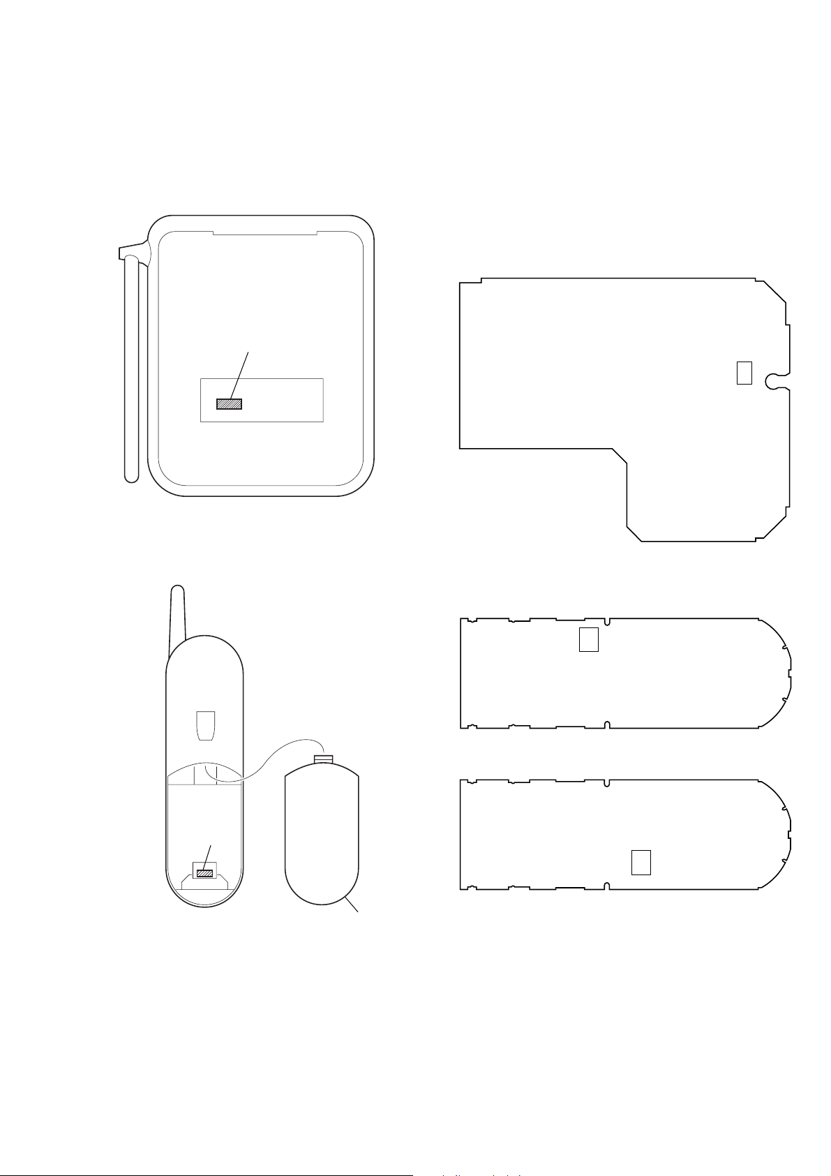
NOTE FOR REPLACEMENT OF THE EEPROM
The ID cord is written in the EEPROM.
When replacing the EEPROM, U6 on the B ASE MAIN board and
U4 on HAND MAIN board should be replaced together as a pair.
(Parts No. X-3381-019-1)
PRIOR CHECK FOR SERVICING
This set can rewrite the ID number of handset to the ID number of
base unit in the test mode even their serial numbers are different.
You can find which is wrong, handset or base unit with this
function.
Note: A normal set is needed for this test.
Define A as the normal set and B as the faulty set.
Disconnect their power.
Procedure:
1. Press the [PGM] key .
2. Select the “DIAL MODE” menu by pressing v or V keys.
3. Press the key sequence [SELECT], [2], [1], [0], [4].
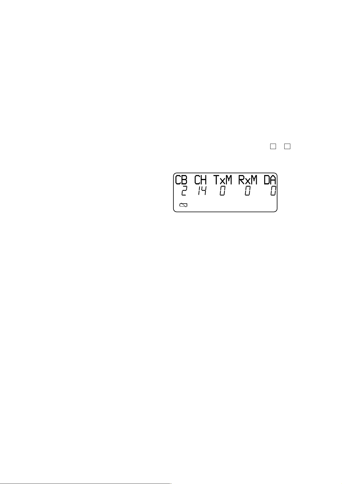
4. When enter the test mode, happ y tone is emitted, and the LCD
displays as shown below.
6. EXPLODED VIEWS
6-1. Hand Set Section ............................................................. 20
6-2. Base Set Section.............................................................. 20
7. ELECTRICAL PARTS LIST ............................... 21
Notes on chip component replacement
• Never reuse a disconnected chip component.
• Notice that the minus side of a tantalum capacitor may be damaged by heat.
SAFETY-RELATED COMPONENT WARNING!!
COMPONENTS IDENTIFIED BY MARK 0 OR DOTTED
LINE WITH MARK 0 ON THE SCHEMATIC DIAGRAMS
AND IN THE PARTS LIST ARE CRITICAL TO SAFE
OPERATION. REPLACE THESE COMPONENTS WITH
SONY PARTS WHOSE PART NUMBERS APPEAR AS
SHOWN IN THIS MANU AL OR IN SUPPLEMENTS PUBLISHED BY SONY.
5. While pressing the [HANDSET LOCATOR] key of the base
unit A, turn the po wer on, then release and press it again within
2 seconds to enter the test mode.
6. When enter the test mode, the
7. Disconnect the po wer of the handset B, then connect the power
again.
8. Disconnect the power of the base unit A, then connect the po wer
again.
9. Cradle the handset B on the base unit A to charge the battery
of handset B for about 1 minute.
10. Press the [TALK] key of the handset B and join the base unit
A.
11. When joining is successful, the handset B is normal. But when
it fails, charge the battery of the handset B again.
12. Next, repeat the step 1 to step 9 with the handset A and base
unit B
13. When joining is successful with handset A and base unit B,
base unit B is normal and handset B is faulty.
[LINE] LED blinks slowly .
ATTENTION AU COMPOSANT AYANT RAPPORT
À LA SÉCURITÉ!
LES COMPOSANTS IDENTIFIÉS P AR UNE MARQUE 0
SUR LES DIAGRAMMES SCHÉMATIQUES ET LA LISTE
DES PIÈCES SONT CRITIQUES POUR LA SÉCURITÉ
DE FONCTIONNEMENT. NE REMPLACER CES COMPOSANTS QUE PAR DES PIÈCES SONY DONT LES
NUMÉROS SONT DONNÉS DANS CE MANUEL OU
DANS LES SUPPLÉMENTS PUBLIÉS PAR SONY.
2
SPP-A1070/A1071
y
– BASE MAIN BOARD (Conductor Side) –
U6
Ver 1.1
NEW/FORMER TYPE DISCRIMINATION
In this set with the following serial No. or later BASE MAIN and
HAND MAIN boards have been changed.
SPP-A1070 : Serial No. 0316344 or later
SPP-A1071 : Serial No. A0103501 or later
Serial No.
NOTE FOR REPAIRING AND REPLACEMENT OF THE
NEW TYPE BOARD
When a new type board is damaged or out of order, do not repair
that board, but replace with an former type board (BASE MAIN
board : Part No. A-3062-656-A, HAND MAIN board : Part No.
A-3062-658-A (A1070)/A-3062-742-A(A1071)). In this case, remove the EEPROM (BASE MAIN board : Ref No. U6, HAND
MAIN board : Ref No. U4) from the new type board and install it
on the former type board as a replacement.
Bottom View
Serial No.
Bottom View
– HAND MAIN BOARD (Component Side) –
U4
Former T ype
U4
New Type
Lid Batter
3
SPP-A1070/A1071
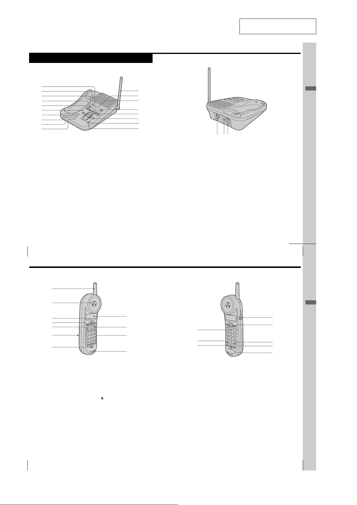
Identifying the parts
Refer to the pages indicated in parentheses for details.
Base Unit
SECTION 2
GENERAL
This section is extracted from
instruction manual.
1
2
3
4
5
6
7
8
9
0
1 Message counter (p. 35, 61)
Indicates the number of new
messages recorded. “A” appears in
the announcement only mode. “F”
appears when there is no space to
record messages. “CL” flashes
when the power is turned on.
2 REC/MEMO button (p. 31, 41)
Press to record a greeting.
Also used to record a memo
message.
3 ERASE button (p. 32, 38)
Erases the recorded greeting or
messages.
4 SELECT button (p. 30)
Press to enter the selection and
bring you to the next selection.
5 TIME/SET button (p. 30)
Press to check the current time.
Also used to set the timer of the
base unit.
US
Getting Started
14
qa
qs
qd
qf
qg
qh
qj
qk
6 REPEAT/SLOW button (p. 37)
Press to repeat the current message.
Also used to go back to the
previous message or to play the
message slowly.
7 NEW CALL lamp (p. 46)
Flashes when there is a “NEW”
data in the Caller ID list.
8 CHARGE lamp (p. 9, 19)
Lights while the battery is being
charged.
9 LINE lamp (p. 18)
Lights when the handset is in use.
0 MIC (microphone) (p. 31, 41)
qa Antenna (p. 7, 54)
qs MENU button (p. 30, 42)
Press repeatedly to select a setting
item when setting up the answering
machine.
w;waql
qd Speaker (p. 38)
qf
ANSWER ON/OFF button (p. 35)
Turns the answering function on or
off. Lights when the answering
function is on, and flashes when a
new message is recorded.
qg VOLUME +/– buttons (p. 38)
Adjusts the speaker volume.
qh SKIP/QUICK button (p. 37)
Press to skip to the next message.
Keep the button pressed for quick
playback of messages.
qj PLAY/STOP (MAILBOX 1, 2, 3)
buttons (p. 37, 38)
Plays back the messages in each
mail box.
qk HANDSET LOCATOR button
(p. 29)
Allows you to page the handset.
ql Hook for AC power adaptor
cord (p. 7)
w; DC IN 9V jack (p. 7)
wa LINE (telephone line) jack
(p. 7)
continued
Getting Started
Getting Started
US
15
Identifying the parts (continued)
Handset
1
2
3
4
5
6
7
1 Antenna
2 Speaker
3 Jog lever (p. 11, 22, 46)
4 HOLD button (p. 18)
Press to put a call on hold.
5 TALK button (p. 18)
Lets you make or receive a call.
6 Battery compartment (p. 9)
7 CHANNEL button (p. 18)
Press to select a better channel.
8 Display (p. 11, 45)
9 OFF button (p. 18)
Allows you to disconnect the call.
8
9
0
qa
0 Dialing keys
qa Microphone
qs FLASH button (p. 18, 53)
Switches to a second call if you
have “call waiting” service, or lets
you make a new call.
qd TONE button (p. 18)
Allows you to switch temporarily to
tone dialing.
qf ONE-TOUCH button (p. 23)
qg I (HEADSET) jack (p. 56)
qh SELECT button (p. 11, 22, 24, 48)
Press to enter the selection and
bring you to the next selection.
qs
qd
qf
qj # button (p. 51)
Used to change the number of digits
of the phone number in the Caller
ID list.
qk REDIAL/PAUSE button
(p. 20, 23)
Redials the last number called/
inserts a pause in the dialing
sequence.
ql PGM (Program) button
(p. 11, 22, 24)
Press to start the procedure for
setting up the phone such as
choosing the dialing mode.
Also used to store the setting to
finish the procedure.
Getting Started
qg
qh
qj
qk
ql
4
US
16
Getting Started
Getting Started
US
17
• This set can be disassembled in the order shown below.
3-1. DISASSEMBLY FLOW
SPP-A1070/A1071
SECTION 3
DISASSEMBLY
Set
Note: Follow the disassembly procedure in the numerical order given.
H/S rear assy H/S FRT assy
Base bottom
BASE MAIN board
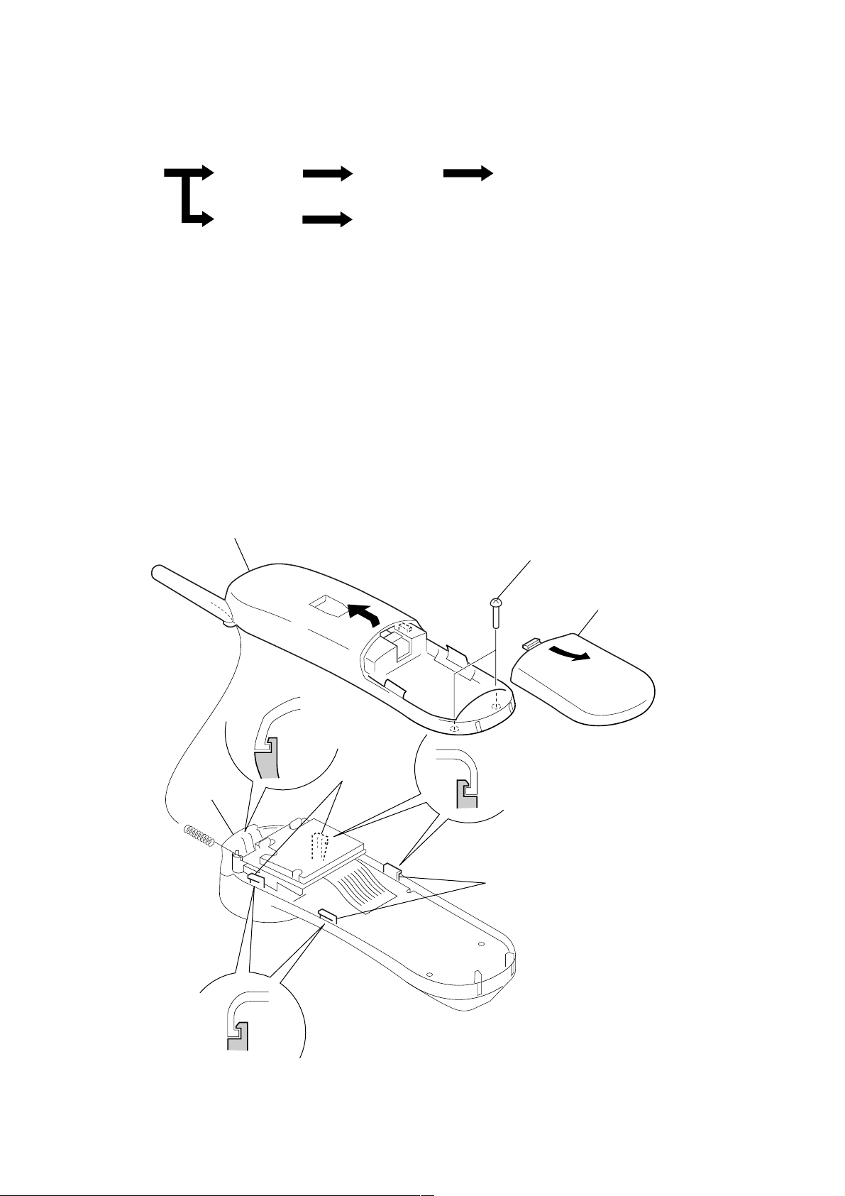
3-2. H/S REAR ASSY
5
Remove the H/S rear assy
in the direction of arrow
B
.
HAND MAIN board
2
two screws
(BTP3
×
10)
4
claw
B
3
two claws
3
two claws
A
1
Remove the battery lid
in the direction of arrow
A
.
5
SPP-A1070/A1071
d
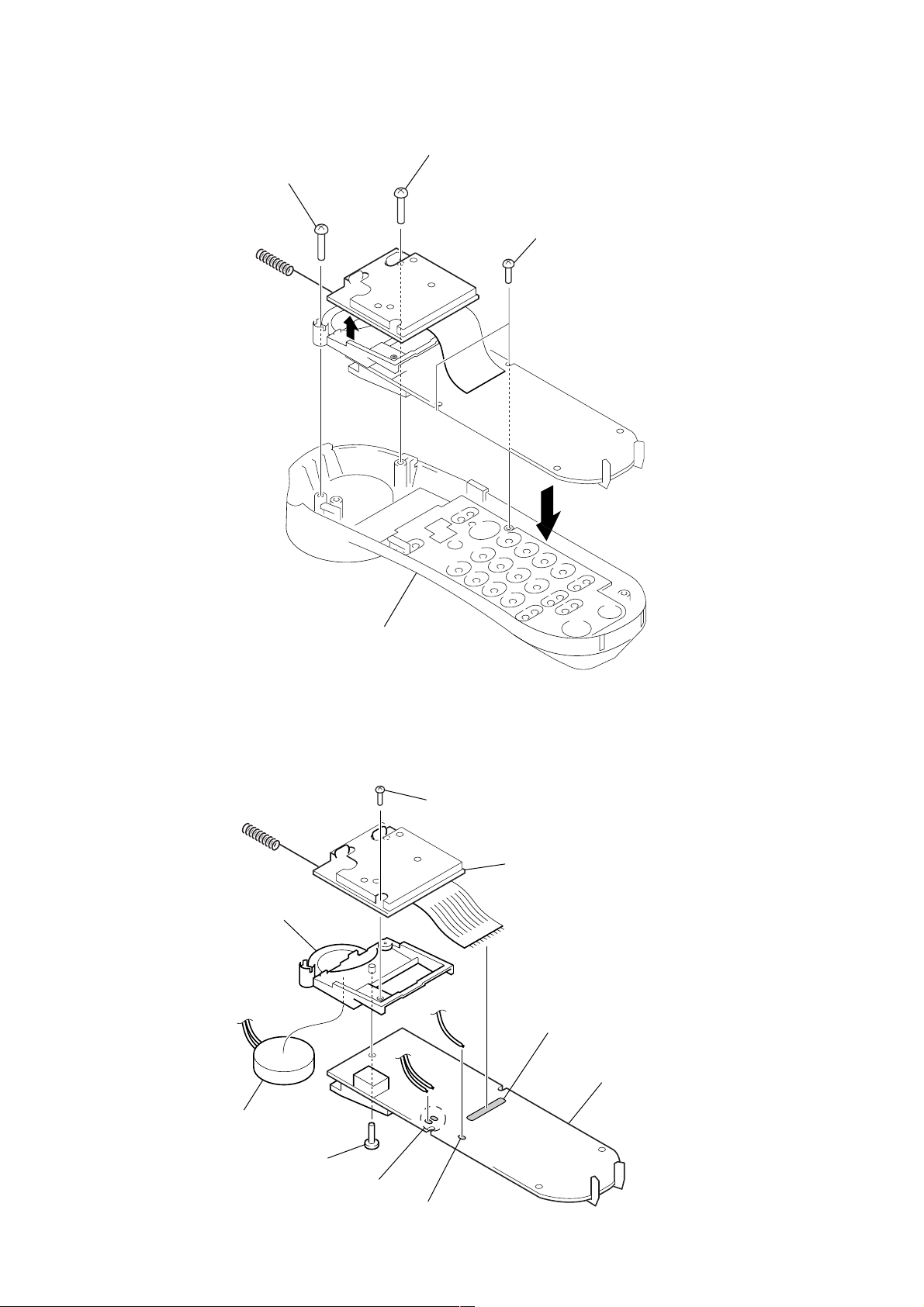
3-3. H/S FRT ASSY
3
screw
(BTP2.6
1
screw
(BTP2.6
×
8)
2
×
8)
4
two screws
(P2
×
5)
3-4. HAND MAIN BOARD
8
receiver BKT
6
H/S FRT assy
5
screw
(BTP2.6
×
8)
6
RF unit (hand)
5
4
Remove twelve solders.
9
HAND MAIN boar
2
speaker (2.8cm)
7
screw (BTP2.6 × 8)
1
Remove two solders of lead.
3
Remove solder of lead.
6
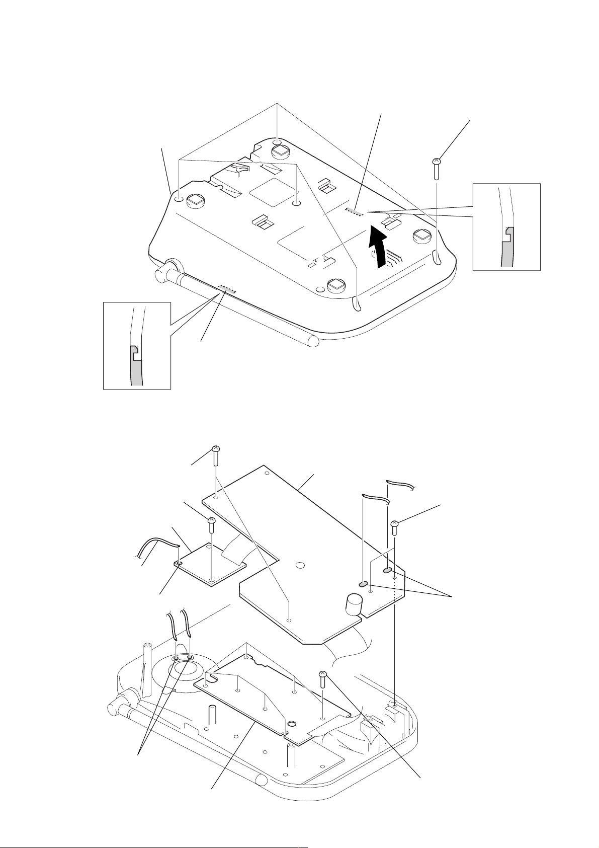
3-5. BASE BOTTOM
3
base bottom
2
claw
SPP-A1070/A1071
1
five screws
×
12)
(P3
2
3-6. BASE MAIN BOARD
6
two screws
(BTP2.6
3
screw
(BTP2.6
4
RF unit (base)
2
harness
1
Remove solder of lead.
×
8)
×
8)
claw
8
BASE MAIN board
7
two screws
(BTP2.6
×
6)
5
Remove two solders of lead.
9
Remove two solders of lead.
qa
BASE KEY board
0
seven screws
(BTP2.6
×
8)
7
SPP-A1070/A1071
SECTION 4
TEST MODE
Introduction
The manual test mode can be used for testing the RF and audio
sections of the base unit and handset. The manual test mode is
also required for the FCC testing in which the phone is tested for
interference at the first, middle, and last RF channels.
The following features are provided in manual test mode.
• Able to set operating mode of the combo chip.
• Able to mute or unmute the audio path.
• Able to change the RF channel. (Both RX and TX)
• Able to transmit or receive data packet.
• Able to synchronize the security code.
BASE UNIT
1. Entering the Manual Test Mode
1. While pressing the [HANDSET LOCATOR] key, tur n the
power on, then releasing and pressing it again within 2
seconds.
2. When enter the test mode, the [LINE] LED blinks slowly.
2. Default Settings
• Channel set to 14. (out of 0 to 29)
• Combo set to active mode.
• TX audio path unmuted.
• RX audio path unmuted.
• Off hooked.
• Date transmission disabled.
4. Data Link
Data bits are encoded in manchester format for which bit “0” is
represented by 500 µs low and 500 µs high while bit “1” by 500
µs high and 500 µs low.
If data transmission is enabled, it will transmit data packet with
the following fields continuously.
(“0”=500 µs low and “1”=500 µs high)
• 8 bit preamble :0101010101010101
• 8 bit word sync :0110010010010110
• 20 bit security code :Restored from EEPROM
• 4 bit reserved data :01010101
• 8 bit command :0101010101010101
• 8 bit data :0101010101010101
If data transmission is enabled, it will toggle the [LINE] LED every
time when a data packet is received. (No security code would be
checked)
HANDSET
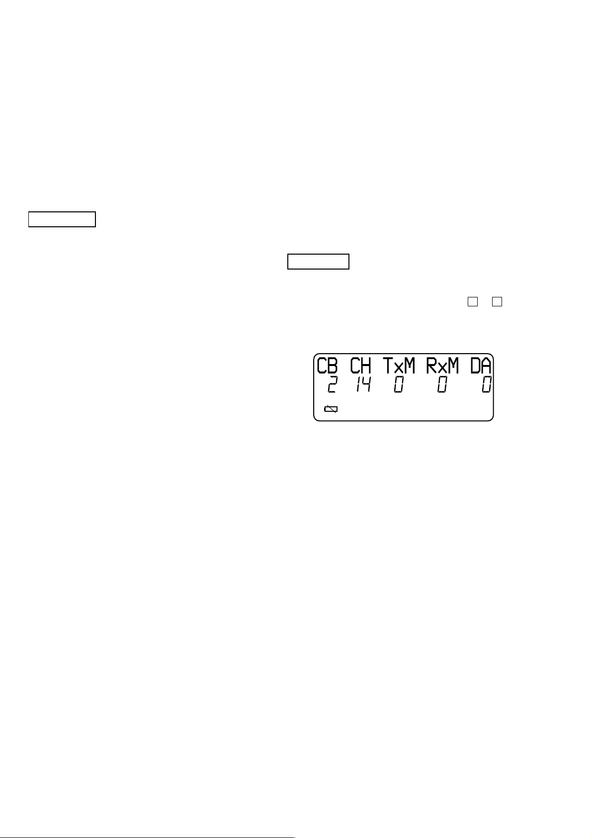
1. Entering the Manual Test Mode
1. Press the [PGM] key.
2. Select the “DIAL MODE” menu by pressing v or V keys.
3. Press the key sequence [SELECT], [2], [1], [0], [4].
4. When enter the test mode, happ y tone is emitted, and the LCD
displays as shown below.
3. HANDSET LOCATOR Key Operation
1.
Condition: Press the [HANDSET LOCATOR] key while the [LINE]
LED lights up.
Operation: Advance channel by one, following 15, 16, 17...28, 29,
0, 1....
Indication:LED remains on for 3 seconds and then blinks again.
2.
Condition: Press the [HANDSET LOCATOR] key while the [LINE]
LED goes off.
Operation: Toggle combo between active mode and RX mode.
Indication:LED remains off for 3 seconds and then blinks again.
3.
Condition: Press the [HANDSET LOCATOR] key over 2 seconds.
Operation: Enable data transmission.
Set combo to active mode.
Indication:LED toggles once and then remains steady.
4.
Condition: Press the [HANDSET LOCATOR] key while data
transmission is enabled.
Operation: Disable data transmission.
Set combo to RX mode.
Indication:LED is on for 1 seconds and then blinks again.
2. Default Settings
• Channel set to 14. (out of 00 to 29)
• Combo set to active mode.
(0: inactive mode, 1: RX mode, 2: active mode)
• TX audio path unmuted. (0: unmuted, 1: muted)
• RX audio path unmuted. (0: unmuted, 1: muted)
• Date transmission disabled. (0: disabled, 1: enabled)
• Battery detection.
(“E” icon on: RSSI detection, “E” icon off: battery detection)
5.
Condition: Power down.
Operation: Release the test mode
8
 Loading...