

Sony SPP-98, SPP-99 Service Manual
SPP-98/99
SERVICE MANUAL
Handset
Photo: SPP-98
SPECIFICATIONS
General
Operating channel
10 channels
Dial signal
Tone, 10 PPS (pulse) selectable
Supplied accessories
AC power adaptor (AC-T47) (1)
Telephone line cord (1)
Rechargeable battery pack (BP-T16) (1) (SPP-98)
Rechargeable battery pack (BP-T16) (2) (SPP-99)
Wall bracket/stand (1)
Screws (2)
Handset
Power source
Rechargeable battery pack BP-T16
Battery life
Standby: Approx. 8 days
Talk : Approx. 6 hours
Battery charging time
Approx. 12 hours
Dimensions
Approx. 54 × 195 × 49 mm (w/h/d),
antenna excluded
(approx. 2 1/4 × 7 3/4 × 1 15/16 inches)
Antenna: Approx. 285 mm
(approx. 11 1/4 inches)
Mass
Approx. 240 g (approx. 8 oz), battery
included
Singapore Model
Base unit
Base unit
Power source
DC 9V from AC power adaptor
Rechargeable battery pack BP-T16
(SPP-99 only)
Battery charging time
Approx. 20 hours (SPP-99 only)
Dimensions
Approx. 120 × 64 × 223 mm (w/h/d),
antenna excluded
(approx. 4 3/4 × 2 5/8 × 8 7/8 inches)
Antenna: Approx. 680 mm
(approx. 26 7/8 inches)
Mass
Approx. 350 g (approx. 12 oz), wall
bracket and battery excluded
Design and specifications are subject to change without
notice.
MICROFILM
CORDLESS TELEPHONE
– 1 –

TABLE OF CONTENTS
1. GENERAL
Read this first........................................................................... 3
Checking the package contents ............................................... 3
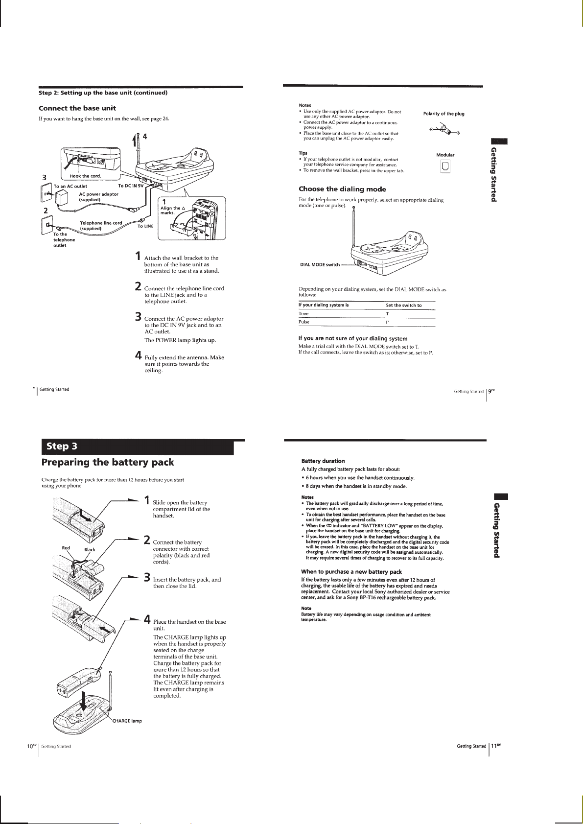
Setting up the base unit ........................................................... 3
Preparing the battery pack .......................................................4
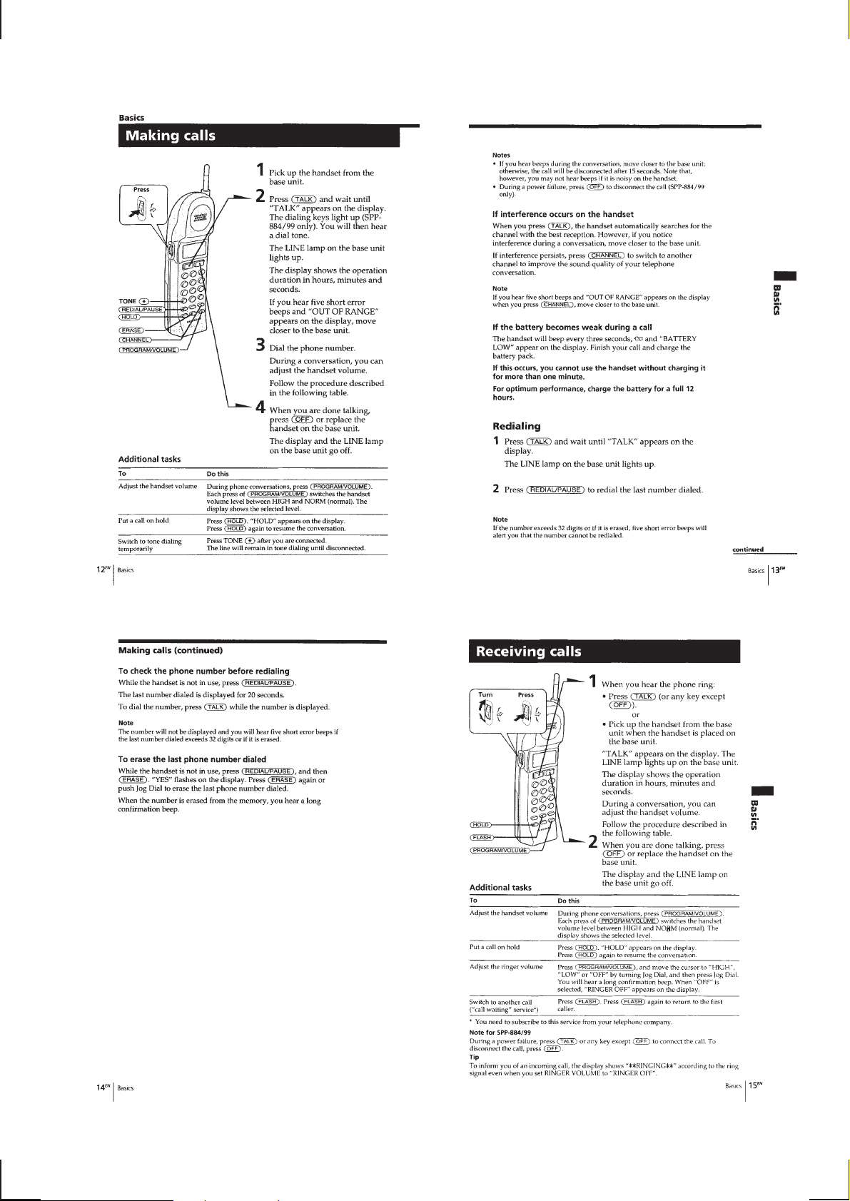
Making calls ............................................................................ 5
Receiving calls......................................................................... 5
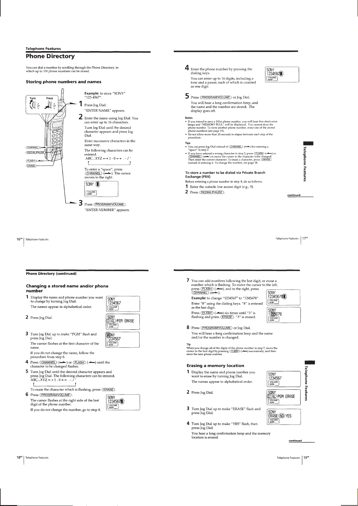
Phone Directory....................................................................... 6
Paging ......................................................................................7
Resetting the digital security code........................................... 7
Mounting the base unit on a wall ............................................ 8
2. DISASSEMBLY
2-1. Cabinet (Lower) .................................................................. 9
2-2. Base Main board ............................................................... 10
2-3. Cabinet (Rear) ................................................................... 11
2-4. Hand Main Board ..............................................................11
3. TEST MODE
Base Unit Section .................................................................. 12
Handset Section .....................................................................14
4. ELECTRICAL ADJUSTMENTS
Base Unit Section .................................................................. 17
Handset Section .....................................................................19
5. DIAGRAMS
5-1. Block Diagram –Base Section– ........................................ 21
5-2. Block Diagram –Handset Section– ................................... 23
5-3. Printed Wiring Board –Base Section–............................... 25
5-4. Schematic Diagram –Base Section– ................................. 27
5-5. Printed Wiring Board –Hand Main Section– ....................29
5-6. Schematic Diagram –Hand Main Section– .......................31
5-7. Printed Wiring Board –Hand Key Section– ...................... 33
5-8. Schematic Diagram –Hand Key Section–......................... 35
5-9. IC Pin Descriptions ........................................................... 38
6. EXPLODED VIEWS
6-1. Base Unit Section ..............................................................40
6-2. Handset Section................................................................. 41
7. ELECTRICAL PARTS LIST ........................................ 42
Notes on Chip Component Replacement
• Never reuse a disconnected chip component.
• Notice that the minus side of a tantalum capacitor may be dam-
aged by heat.
SAFETY-RELATED COMPONENT WARNING!!
COMPONENTS IDENTIFIED BY MARK ! OR DOTTED LINE
WITH MARK ! ON THE SCHEMATIC DIAGRAMS AND IN
THE PARTS LIST ARE CRITICAL TO SAFE OPERATION.
REPLACE THESE COMPONENTS WITH SONY PAR TS WHOSE
P ART NUMBERS APPEAR AS SHOWN IN THIS MANUAL OR
IN SUPPLEMENTS PUBLISHED BY SONY.
– 2 –

SECTION 1
GENERAL
This section is extracted
from instruction manual.
– 3 –
– 4 –
– 5 –
– 6 –

– 7 –

– 8 –
SECTION 2
0
DISASSEMBLY
Note : Follow the disassembly procedure in the numerical order given.
2-1. CABINET (LOWER)
1
BTP 3x10
3
5
4
2
BTP 3x1
6
cabinet (lower)
– 9 –
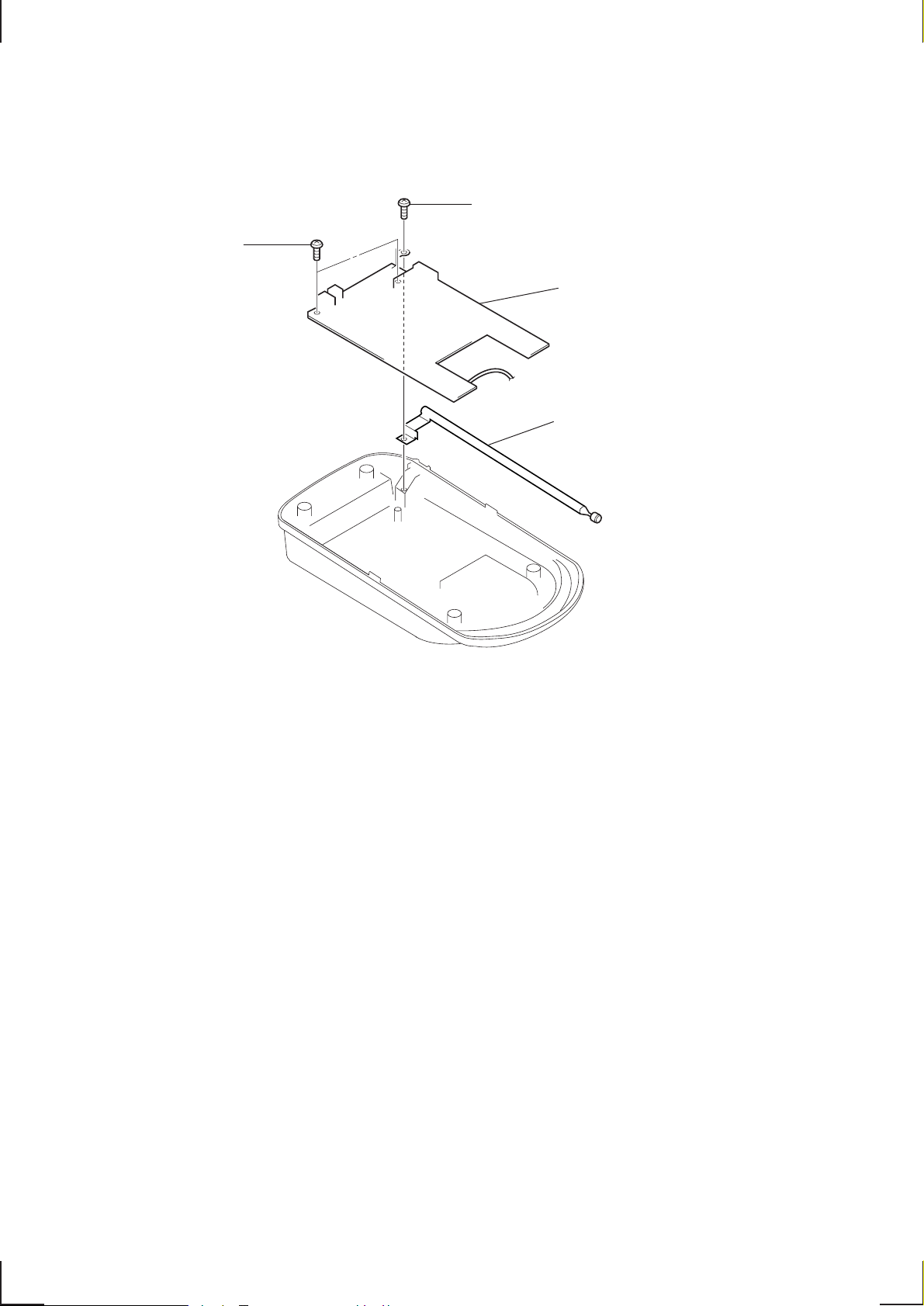
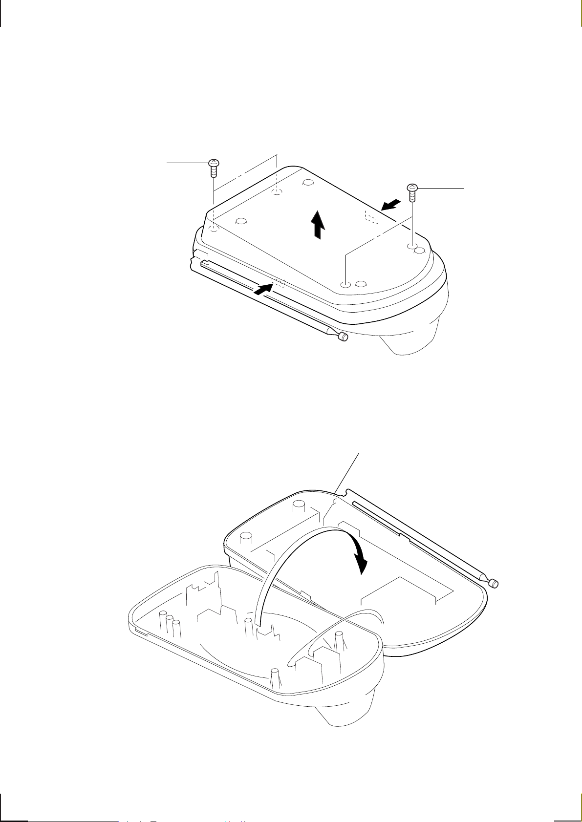
2-2. BASE MAIN BOARD
1
BTP 2.6x8
2
BTP 2.6x8
3
BASE MAIN board
4
telescopic antenna
– 10 –

2-3. CABINET (REAR)
5
claw
6
cabinet (rear)
4
claws
3
claws
1
battery lid
2
BTP 2.6x10
2-4. HAND MAIN BOARD
discharge gap (CP101)
4
Unsolder the
3 wires.
8
HAND MAIN board
5
!¡
HAND KEY board
!£
speaker
Unsolder.
3
BTP 2x8
7
Unsolder.
2
BTP 2x8
9
1 CN3
BVTP 2x8
!º
terminals
6
Unsolder.
!™
claws
– 11 –
SECTION 3
TEST MODE
BASE UNIT SECTION
MANUAL TEST MODE
Set the Test Mode:
1. Set the DIAL MODE switch to “P” (pulse).
2. While pressing the HANDSET LOCATOR key, insert the AC
adaptor (Reset start).
3. With the HANDSET LOCATOR key still held down, switch
the DIAL MODE switch “T” (tone) n “P” (pulse).
4. When the HANDSET LOCATOR key is released, test mode
starts.
5. The LEDs POWER , LINE and CHARGE light on one after
another with a 0.5 sec interval in this order. When all of them
are on, they will light off in 1 sec.
Firstly, “0” will be dialled out at 10 pps. Then “1”, “4”, “8”
and “#” will be sent out by DTMF.
6. Set to TX ON. Goes to external line state in 1 CH. (LINE LED
light on)
Release the Test Mode:
1. Pull out the AC adaptor or turn off the power.
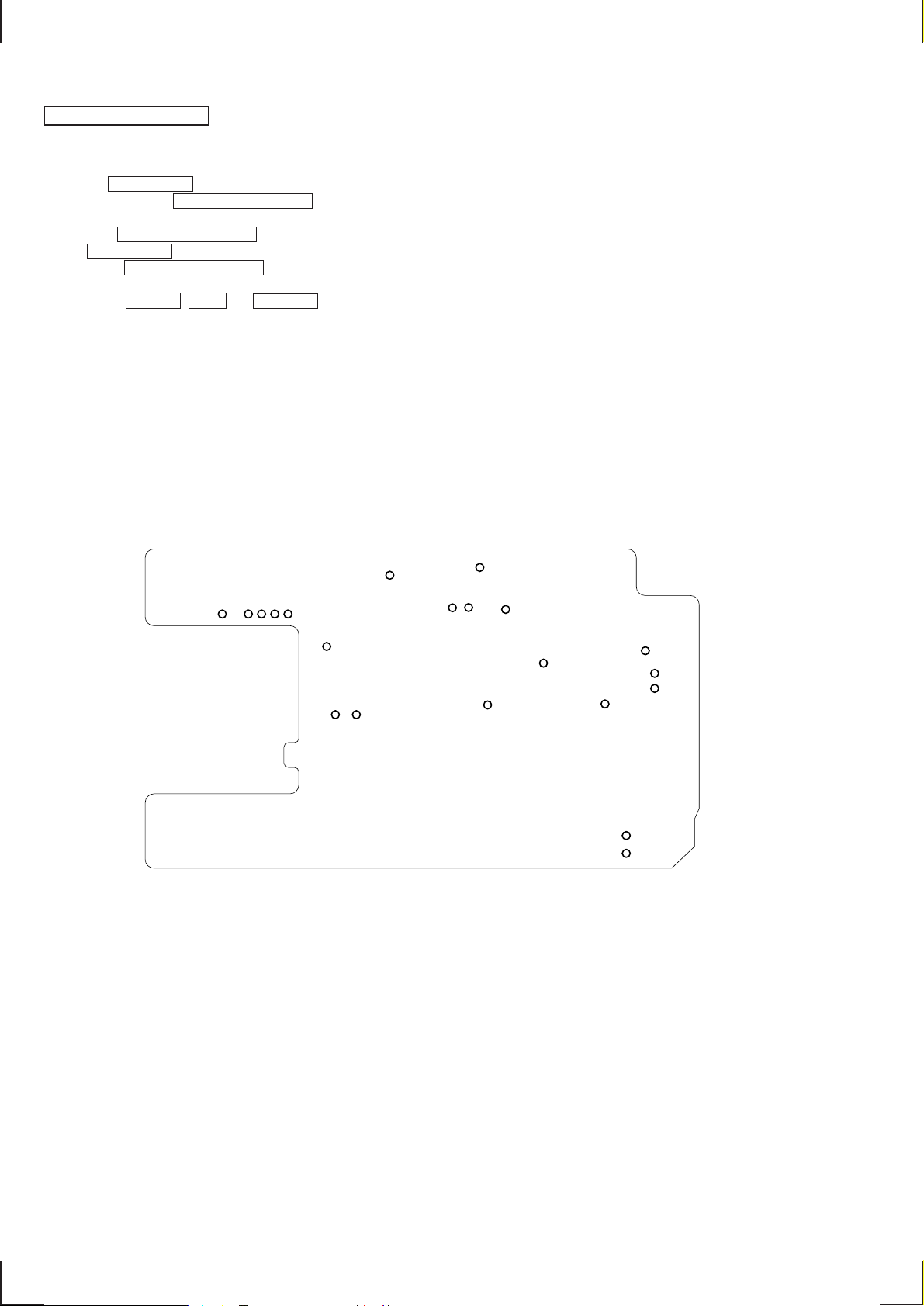
– base main board (conductor side) –
MACHINE TEST MODE
Set the Test Mode:
1. With the TEST I/O (TP808) terminal in “L” (low) input state,
cause Reset of Power ON. Equipment enters machine test mode.
2. With the timing of marking the TEST I/O terminal “H” (high)
100 ms after the power is turned on, use the TEST CLK and
COL1-4 information to set up.
3. ON/OFF of TX is according to the input logic of the DIAL
MODE terminal.
Release the Test Mode:
1. Pull out the AC adaptor or turn off the power.
2. Remove the short plug and turn on the power again.
TP808
TP807
TP809
TP805
TP806
TP811 TP812
TP804
TP814
TP813
– 12 –
 Loading...