

Page 1

3-862-974-11 (1)
i^fT-
Video Cassette
Recorder
Hookup/Setup
VMS
n n=ia
GOLD
SLV-M20HF
©1998 by Sony Corporation
G E M S TA 17
yiOEi^
Page 2

Precautions
Safety
• Operate the unit only on 120 V AC, 60 Hz.
• If anything falls into the cabinet, unplug the unit
and have it checked by qualified personnel
before operating it any further.
• This unit is not disconnected from the AC
power source (mains) as long as it is connected
to the wall outlet, even if the unit itself has been
turned off.
• One blade of the plug is wider than the other for
the purpose of safety and will fit into the power
outlet only one way. If you are unable to insert
the plug fully into the-outlet, contact your Sony
dealer.
• Unplug the unit from the wall outlet if you do
not intend to use it for an extended period of
time. To disconnect the cord, pull it out by the
plug, never by the cord.
Installing
• Allow adequate air circulation to prevent
internal heat buildup.
• Do not place the unit on surfaces (rugs,
blankets, etc.) or near materials (curtains,
draperies) that may block the ventilation slots.
• Do not install the unit near heat sources such as
radiators or air ducts, or in a place subject to
direct sunlight, excessive dust, mechanical
vibration or shock.
• Do not install the unit in an inclined position. It
is designed t^ be operated in a horizontal
position only.
• Keep the unit and cassettes away from
equipment with strong magnets, such as
microwave oldens or large loudspeakers.
• Do not place heavy objects on the unit.
• If the unit is brought directly from a cold to a
warm location, moisture may condense inside
the VCR and cause damage to the video head
and tape. When you first install the unit, or
when you move it from a cold to a warm
location, wait for about one hour before
operating the unit.
Page 3

Table of contents
4 Step 1: Unpacking
5 Step 2: Setting up the remote commander
8 Step 3: Hookups
9 Audio/ video (A / V) hookup
11 Hookup 1: Using cable box control
14 Hookup 2: No cable box, or incompatible cable box with only a
few scrambled channels
17 Hookup 3: Antenna hookup
20 Hookup 4: Incompatible cable box with many scrambled
channels f
23 Hookup 5: DSS (Digital Satellite System) receiver
26 Hookup 6: Incompatible cable box with only a few scrambled
channels, using an A / B switch
29 Selecting a language
30 Setting the clock
34 Setting up cable box control
39 Presetting channels
43 General setup information
45 Index to parts and controls
back cover
Index
VCR Plus+, PlusCode and GUIDE Plus+ are trademarks of Gemstar Development Corporation. The
VCR Plus+ and GUIDE Plus+ systems are manufactured under license from Gemstar Development
Corporation and VCR Index Systems B.V., respectively.
Page 4
step 1
Unpacking
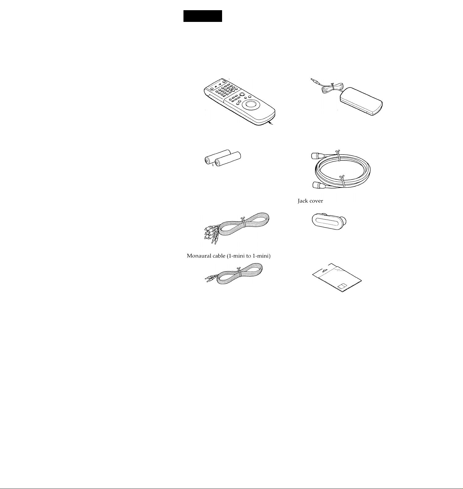
Check that you have received the following items with the VCR:
Remote commander
Size AA (R6) batteries
Audio/video cable (3-phono, 1-mini
to 3-phono, 1-mini)
Cable Mouse (cable box controller)
75-ohm coaxial cable with F-type
connectors
SmartFile labels
Page 5
step 2
Setting up the remote commander
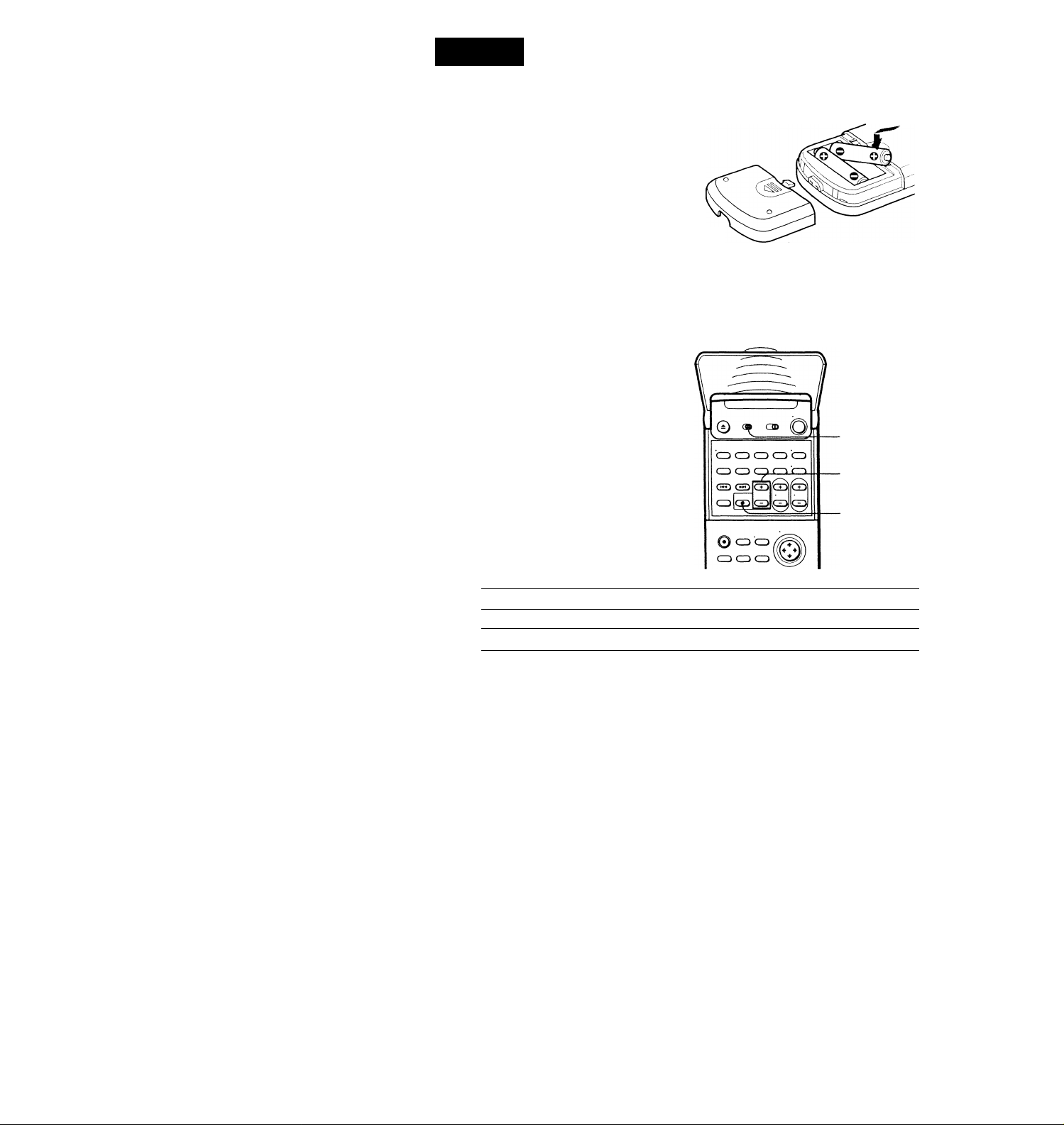
Inserting the batteries
Insert two size AA (R6) batteries by
matching the + and - on the batteries
to the diagram inside the battery
compartment.
Insert the negative (-) end first, then
push in and down until the positive (+)
end clicks into position.
Using the remote commander
You can use this remote
commander to operate this VCR
and a Sony TV or AV receiver.
Buttons on the remote
commander marked with a dot
(•) can be used to operate your
Sony TV.
The RECEIVER VOL + /- and
MUTING buttons can be used to
operate your Sony AV receiver.
To operate
the VCR 1 VIDEO| and point at the remote sensor on the VCR
a Sony TV pTV] and point at the remote sensor on the TV
Notes
• With normal use, the batteries should last about three to six months.
• If you do not use the remote commander for an extended period of time, remove
the batteries to avoid possible damage from battery leakage.
• Do not use a new battery with an old one.
• Do not use different types of batteries.
• Some Sony AV receivers may not be operated with the remote commander.
Set fTVl /¡VIDEO 1 to
Remote sensor
a
[tv|/[\/id^
RECEIVER
VOL +/-
MUTING
continued
Page 6

step 2: Setting up the remote commander (continued)
Setting the COMMAND MODE switch
To remotely control the VCR with
the remote commander, set
COMMAND MODE on the
remote cornmander to the same
position as that on the VCR.
Usually set to VTR 3. Change the
position as shown below to
control other Sony VCRs:
VTR 1: For Sony Betamax format VCRs
VTR 2: For Sony 8mm format VCRs
VTR 3: For Sony VHS format VCRs
To change the command mode
position of the VCR, press and
hold COMMAND MODE on the
VCR for about two seconds and
repeat until the desired position
appears in the display window.
t:
Q (3Û
‘O ■© ■© CD CD
■© ■© ■© CD 'CD
COMMAND MODE
COMMAND
MODE
Controlling other TVs with the remote commander
The remote commander is preprogrammed to control non-Sony TVs. If your TV
is listed in the table below, set the appropriate manufacturer's code number.
1 Set I TV I/ |VIDEO|at the top of the remote commander to |TV|.
2 Hold POWER down, and enter your TV's code number(s) using the
number buttons. Then release POWER.
Now you can use the POWER, VOL +/-, CH +/-, and TV/VIDEO buttons to
control your TV. You can also use the buttons marked with a dot (•) to
control a Sony TV. To control the VCR, reset |TV| /1 VIDEO| to |VIE)EO|.
Tip
• If you set your TV's code number correctly while the TV is turned on, the TV turns
off automatically.
Page 7

Code numbers of controllable TVs
If more than one code number is listed, try entering them one at a time until
you find the one that works with your TV.
Manufacturer
Code
number
Sony 01
Akai
04
AOC 04
Centurion
Coronado
12
03
Curis-Mathes 12
Daytron 12
Emerson
03, 04, 14
Fisher 11
General Electric
06, 10 Pioneer
Gold Star 03, 04, 17
Hitachi 02, 03
J.C.Penny 04, 12
Notes
• If the TV uses a different remote control system from the one programmed to work
with the VCR, you cannot control your TV with the remote commander.
• If you enter a new code number, the code number previously entered will be erased.
• When you replace the batteries of the remote commander, the code number may
automatically reset. Set the appropriate code number every time you replace the
batteries.
Manufacturer
Code
number
JVC 09
KMC
Magnavox
Marantz
03 Sampo
03, 08,12
04, 13
MGA/Mitsubishi 04,12,13,17
NEC 04, 12
Panasonic
Philco
Philips
06,19 Sylvania 08, 12
03, 04 Teknika
08
16 Wards
Portland
Quasar
Radio Shack
03
06, 18 Zenith
05, 14
Manufacturer
Code
number
RCA 04, 10
12
Sanyo
11
Scott 12
Sears 07, 10, 11
Sharp 03, 05, 18
03, 08, 14
Toshiba
07
03, 04, 12
Yorx 12
15
Page 8
step 3
Hookups
Selecting the best hookup option
There are many ways in which your VCR can be hooked up. To hook up
your VCR so that it works best for you, first scan through the table below.
Then use the accompanying diagrams and procedures on the following
pages to set up your VCR.
If you have
TV that has audio/video inputs
Cable box that is compatible with the
VCR's cable box control feature
No cable box or incompatible cable box
with only a few scrambled channels
Antenna only, no cable TV
Incompatible pable box with many
scrambled channels
DSS"' receiver
Incompatible cable box with only a few
scrambled channels, using an A/B
switch
After you've completed the connections, follow the instructions for setup.
During setup, if you need more details on the procedure described, page
numbers are provided where you can find complete, step-by-step
instructions.
After you've completed the setup, you're ready to use your VCR.
Procedures differ depending on the hookup you used. For an overview,
refer to "Quick reference to using the VCR" on the back cover of the
supplied operating instructions.
Before you get started
• Turn off the power to all equipment.
• Do not connect the AC power cords until all of the connections are
completed.
• Be sure you make connections firmly. Loose connections may cause
picture distortion.
• If your TV doesn't match any of the examples provided, see your nearest
Sony dealer or qualified technician.
Use
Audio/video (A/V) hookup, then
follow one of the hookups below.
Hookup 1
Hookup 2
Hookup 3
Hookup 4
Hookup 5
Hookup 6
Refer to
Pages 9 and 10
Pages 11 to 13
Pages 14 to 16
Pages 17 to 19
Pages 20 to 22
Pages 23 to 25
Pages 26 to 28
DSS"' is a registered trademark of DIRECTV, Inc., a unit of Hughes Electronics Corporation.
Page 9
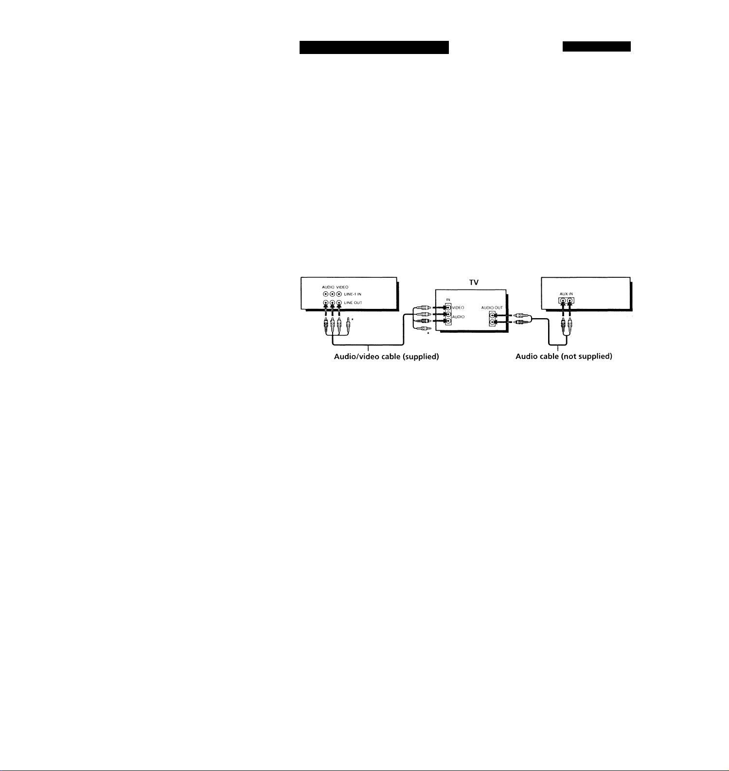
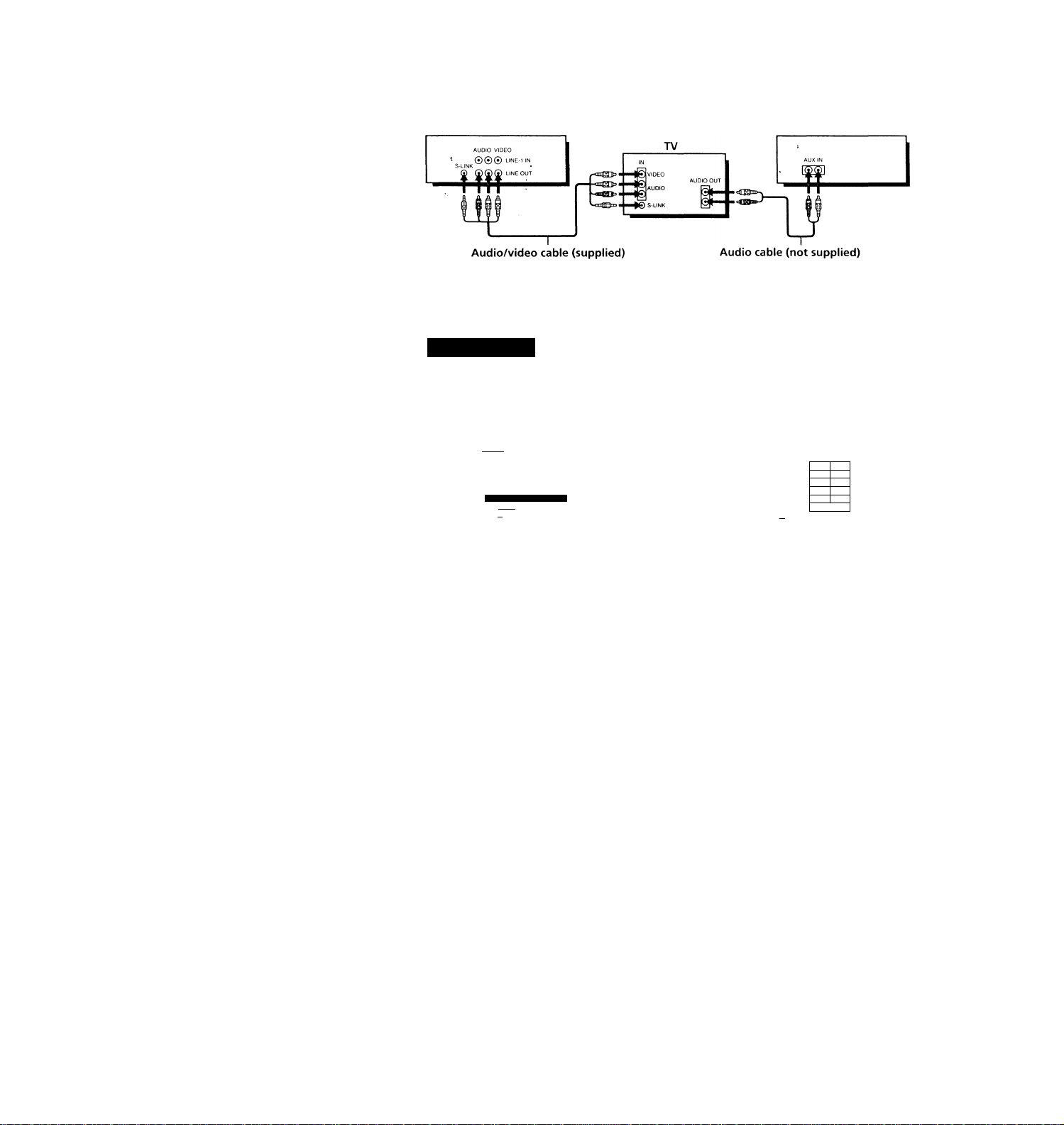
Audio/video (AA/) hookup
If your TV has audio/video (A/V) input jacks, you will get a better picture
and sound if you hook up your VCR using these connections. In addition,
for a true ''home theater" experience, you should connect the audio outputs
of your VCR or TV to your stereo system. If your TV doesn't hav^e A/V
inputs, see the following pages for antenna or cable hookups.
If your TV has the S-Link™’^ (A/V bus control) function, hook up your VCR
using the connection shown on page 10. Your TV will automatically switch
to the A/V inputs for your VCR when you play back or operate menu on the
VCR.
If you're not planning to use your VCR to record programs, you're finished
setting up the VCR after you've made the connections shown on pages 9 and
10. If you want to record off-air or off your cable TV system, complete these
connections first, and then go to the following pages for antenna or cable
hookups.
S-Link^'^’ is a trademark of Sony Corporation.
□ Use this hookup if your TV has stereo jacks
Pages 9 and 10
VCR
Do not connect the miniplugs for this hookup,
m Use this hookup if your TV doesn't have stereo jacks
VCR
VIDEO
AUDIO
TV
AUDIO VIDEO
000 LINE 1 IN
) LINE our
Video cable (not supplied) Audio cable (not supplied)
stereo receiver
Stereo receiver
continued
Page 10
step 3: Hookups (continued)
B Use this hookup if your TV has the S-Link^'^ function
VCR stereo receiver
Note
To play a tape in stereo, must use the A/V connection.
AIM hookup:
After you've connected your TV and completed antenna or cable hookup,
u^e the following procedure to set up the VCR.
Press MENU and select
ADVANCED OPTIONS.
rarggiii
TIMER SET/CHECK
TUNER PRESET
CLOCK SET
LANGUAGE
CABLE BOX CONTROL
ADVANCED OPTIONS
SMARTFILE EDIT
Use M to se I ec
item, then push |
Caution
Connections between the VCR's VHF/UHF connector and the antenna terminals of
the TV receiver should be made only as shown in the following instructions. Failure
to do so may result in operation that violates the regulations of the Federal
Communications Commission regarding the use and operation of RF devices. Never
connect the output of the VCR to an antenna or make simultaneous (parallel) antenna
and VCR connections at the antenna terminals of your receiver.
Note to CATV system installer (in USA)
This reminder is provided to call the CATV system installer's attention to Article 82040 of the NEC that provides guidelines for proper grounding and, in particular,
specifies that the cable ground shall be connected to the grounding system of the
building, as close to the point of cable entry as practical.
VCR setup
Set AUTO ANT SEL to OFF and
press the cursor stick (OK).
ON
AUTO STEREO
AUDIO MIX
TUNER AUDIO
SHARPNESS
DEFAULT SPEED
Use [TT] to select
item,then push
OFF
ON OFF
ON
OFF
SAP
MAIN
riT
EP
- H
For details, refer to page 34 of the
supplied operating instructions.
Page 11
Hookup 1
Using cable box control
Recommended use
You should use this hookup if you have a cable box, especially if your cable
system scrambles all or most channels. This hookup allows the VCR's cable
box control feature to control the channel on the cable box, simplifying the
recording process. A list of compatible cable boxes is on pages 35 and 36.
What you can do with this hookup
• Record any channel using the VCR's cable box control feature to select
What you can't do
• Record with the cable box turned off '
• Record one channel while watching another channel
Pages 11 to 13
channels on the cable box
CONTROL
ipOWEfl ^
VCR
Cable box
Cable Mouse
------
Rear of TV
VHF/UHF
Match the type of
lA
connector on your
TV: A, B, or C.
VHF
-
UHF
For connector types
B and C, no UHF
connection is
required.
VHF
UHF
Positioning the Cable Mouse
Place the Cable Mouse so that it
hangs out over the cable box
front.
r
Side view
.
i
V
........
-------
1 y
continued
Page 12
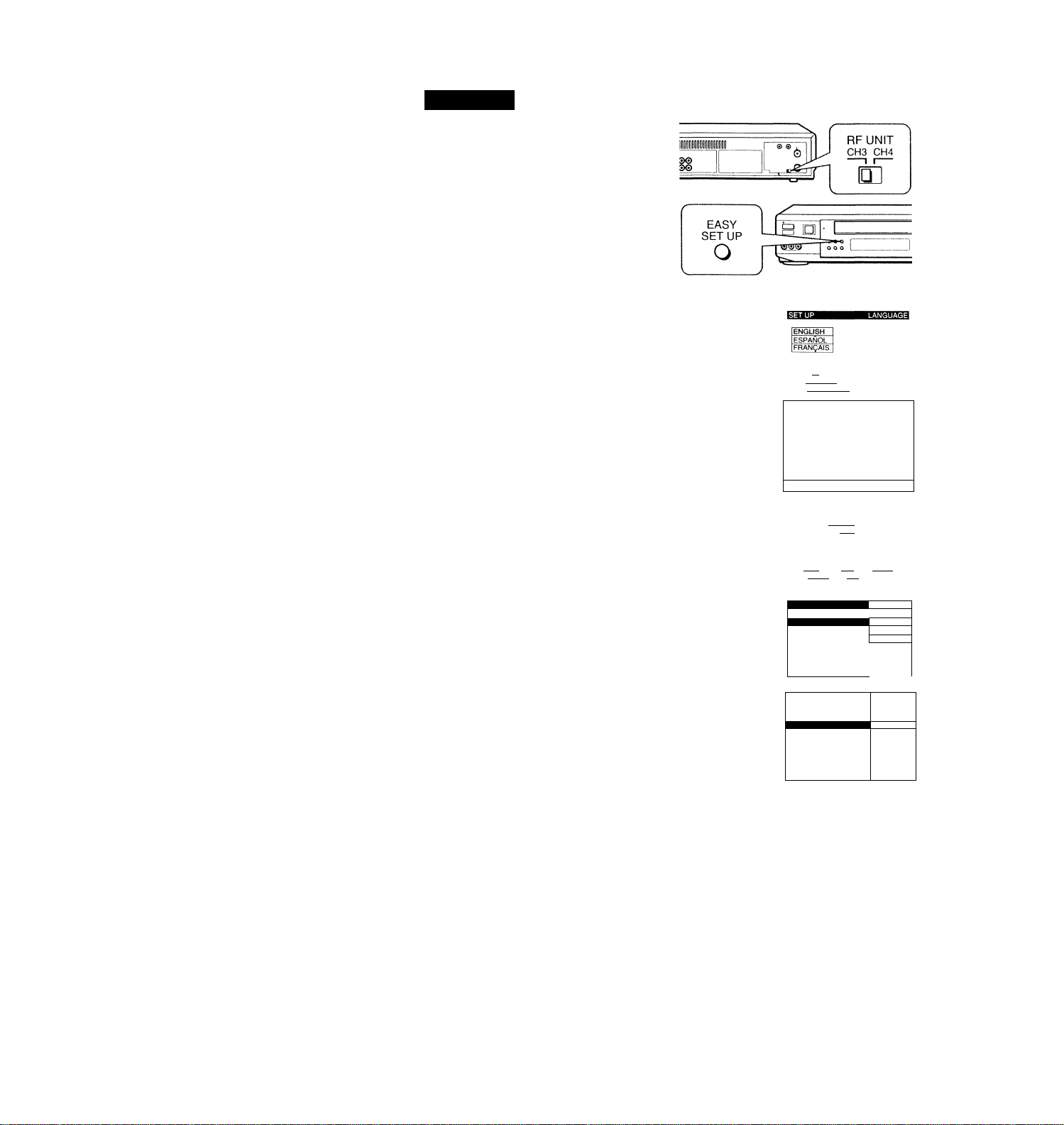
step 3: Hookups (continued)
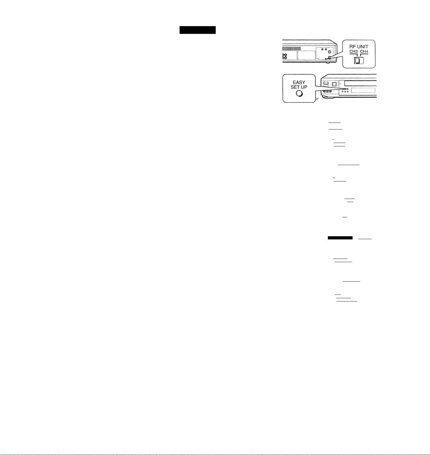
Hookup 1:
1 Set the RF UNIT switch to
Z Turn on your cable box.
3 Press EASY SET Ur»«n the VCR.
VCR setup
CH 3 or CH 4, whichever
channel is not used in your
area. If both are used, set
the switch to either channel.
For details, see page 43.
If you made A/V
connections (from page 9),
you can skip this step.
O The LANGUAGE menu appears. Change the
on-screen display language to Spanish
(ESPAÑOL) or French (FRANÇAIS) if desired,
and press the cursor stick (OK). For details, see
page 29.
© The CLOCK SET menu appears. Select AUTO
and press the cursor stick (OK). For details, see
page 30.
O The ZIP/POSTAL CODE menu appears. Push
the cursor stick to ♦/4'/^/^ to enter the
ZIP/POSTAL CODE in your area and press the
cursor stick (OK). (You can also use the number
buttons to enter the ZIP/POSTAL CODE.)
O The CABLE BOX menu appears. Select ON. For
details, see page 34.
Use 10 se l ec t
Then push [OK]
Push [easy SET~U^ to
— I!
in Ml
lAUTO Manuali
Use |-4--»| t 0
Then push
Push lEASY SET UPl to quit
Enter your ZIP/POSTAL
CODE us i ng |0-9l o r It 4-I
and I-»-»I k e y s
t hen push lok
SET UP (
CABLE BOX CONTROL
CABLE MOUSE
BOX CODE NO.
BOX OUTPUT CH
select
ZIP / POSTAL CODE
IT2^
__________________
ON lOFF 1
=M
CH3 1
© Enter your cable box code number and push the
cursor stick to 4. For details, see page 35.
Use to select
CABLE MOUSE ON lOFF 1
■ BOX CODE NO.
BOX output CH
En t e r your CABLE
Code No. using |0-9
Refer to the Ope
Manua 1 for the C
-----CH3 1
BOX
keys
rat i n g
ode
]
Page 13

© Select your cable box
output channel and
press the cursor stick
(OK).
CABLE BOX CONTROL
CABLE MOUSE
BOX CODE NO.
BOX OUTPUT CH
Use [^3 to select CABLE
BOX CH Then push ^
MiS=J№>q
ME]
1
SET UP IS done
Normal display
Automatic clock setting
Once you've set up the VCR, it automatically sets the clock the first time you
turn off the VCR. After that, whenever you turn off the VCR, it checks the
time and adjusts the clock, even for Daylight SavingT^ime. The VCR sets the
clock by picking up a time signal provided by some TV channels.
If you want to use the timer to record right away, or if th^ channels in your
area do not carry time signals, set the clock manually. For details, see page
32.
Note
• To use the Auto Clock Set feature, leave the cable box on.
continued
Page 14
step 3: Hookups (continued)
Hookup 2
No cable box, or incompatible cable box with only a
few scrambled channels
Recommended use
Use this hookup if you do not have a cable box. Also use this hookup if your
cable company cannot supply a cable box that is compatible with the VCR's
cable box control feature, and your cable system scrambles only a few
channels.
What you can do with this hookup
• Record any unscramh^d channel by selecting the channel on the VCR
What you can't do
• Record scrambled channels that require a cable box
Connect this cable —
directly to your TV if
you don't have a
cable box.
VCR
Cable box
-♦©
OUT
4
Rear of TV
VHF/UHF
lA
—S'
VHF
UHF
VHF
Pages 14 to 16
Match the type
of connector on
your TV: A, B, or
C.
For connector
types B and C, no
UHF connection
is required.
UHF
Page 15
Hookup 2: VCR setup
1 Set the RF UNIT switch to
CH 3 or CH 4, whichever
channel is not used in your
area. If both are used, set
the switch to either channel.
For details, see page 43.
If you made A / V
connections (from page 9),
you can skip this step.
2 Press EASY SET UP on the
VCR.
O The LANGUAGE menu appears. Change the
on-screen display language to Spanish
(ESPAÑOL) or French (FRANÇAIS) if desired,
and press the cursor stick (OK). For details, see
page 29.
0 The CLOCK SET menu appears. Select AUTO
and press the cursor stick (OK). For details, see
page 30.
© The ZIP/POSTAL CODE menu appears. Push
the cursor stick to ♦/♦/4-/-^ to enter the
ZIP / POSTAL CODE in your area and press the
cursor stick (OK). (You can also use the number
buttons to enter the ZIP/POSTAL CODE.)
O The CABLE BOX menu appears. Select OFF and
press the cursor stick (OK).
ENGLISH
FRANÇAIS
Use It to select
Then push |0K|
Push [easy set to quit
IAUTQ IMANUALI
Use ♦! to select
Then push |OI^
en push |dl^
Push
sh [easy set UP| to quit
ZIP / POSTAL CODE
Il23^
Enter your ZIP/POSTAL
CODE using [O^ or [Q
and keys,
then push Iok]
CABLE BOX CONTROL
__________________
CABLE MOUSE
tON lOFF 1
© The TUNER PRESET menu aj^pears. Set
ANTENNA/CABLE to CABLE and press the
cursor stick (OK). For details, see page 40.
Use Ittl to select
Push IeASY set UPl to quit
ANTENNA / CABLE
[ÁÑT CABLE I
Use |t-»| to select
Then push jOKj
Push [easy SET~U^ to quit
______
continued
Page 16

step 3: Hookups (continued)
O The AUTO PRESET
starts.
AUTO PRESET
-PI ease wa i t-
PROCESS 1NG
SET UP is done
i
Normal display
Automatic clock setting
Once you've set up the VCR, it automatically sets the clock the first time you
turn off the VCR. After that, whenever you turn off the VCR, it checks the
time and adjusts the clocj^even for Daylight Saving Time. The VCR sets the
clock by picking up a time signal provided by some TV channels.
If you want to use the timer to record right away, or if the channels in your
area do not carry time signals, set the clock manually. For details, see page
32.
Page 17

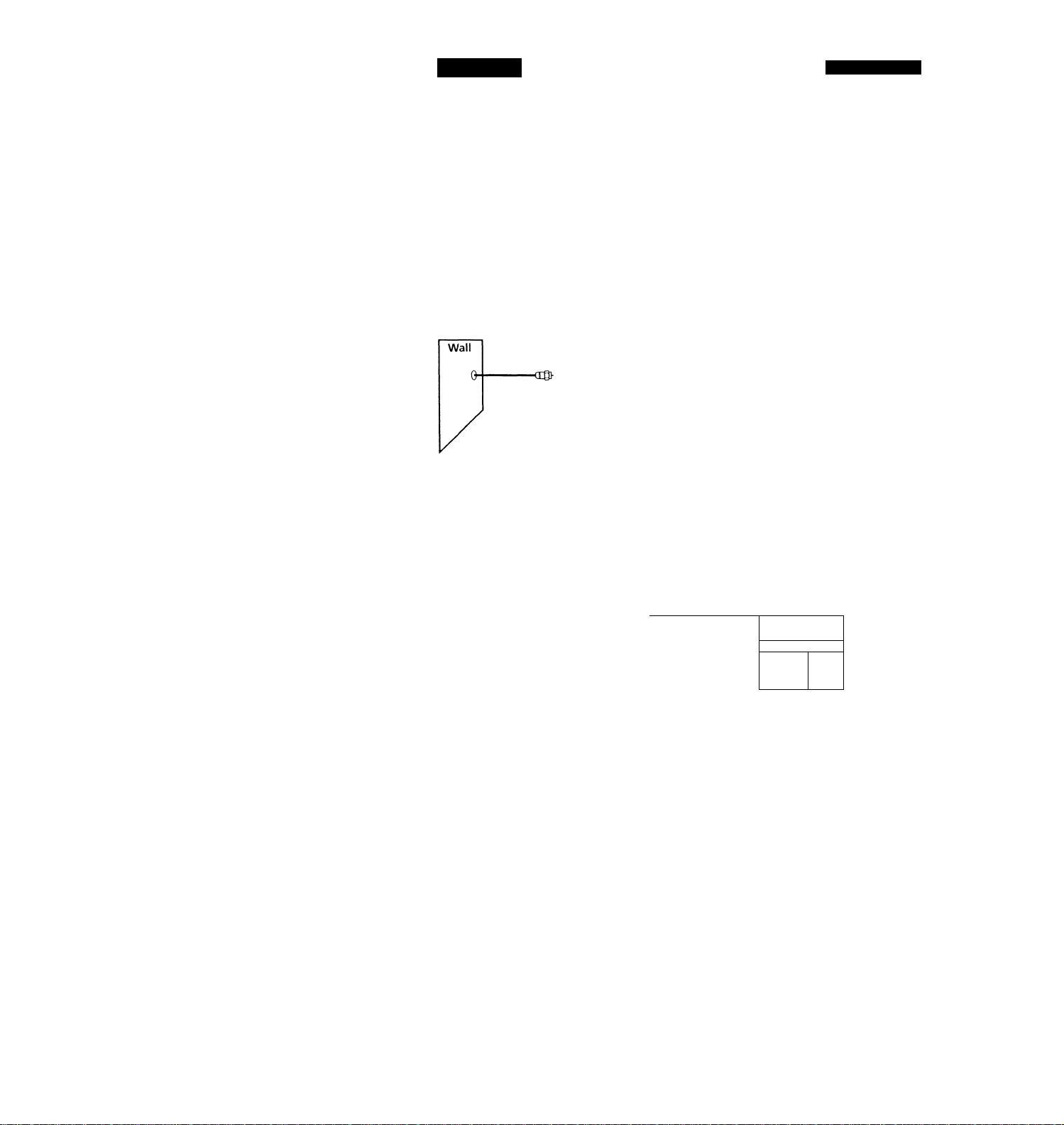
Hookup 3
Antenna hookup
Make the following connections if you're using an antenna (if you don't
have cable TV).
□ Use this hookup if you're using:
• VHF/UHF antenna (you get channels 2-13 and channels 14 and higher)
• UHF-only antenna (you get channels 14 and higher)
• Separate VFIF and UHF antennas
B Use this hookup if you're using a VHF-only antenna (you get
HJD»-
.........
channels 2-13 only)
Rear of TV
VHF/UHF
-----
....................................... CSD wwii»
Rear of TV
VHF/UHF
■-—H@ A
—il'
Pages 17 to 19
@A f Match the type of
connector on your
TV; A, B, or C.
B
UHF
VHF
-
UHF
Match the type of
connector on your
TV; A, B, or G.
VHF
For connector types
B and C no UHF
UHF
connection is
required.
VHF
UHF
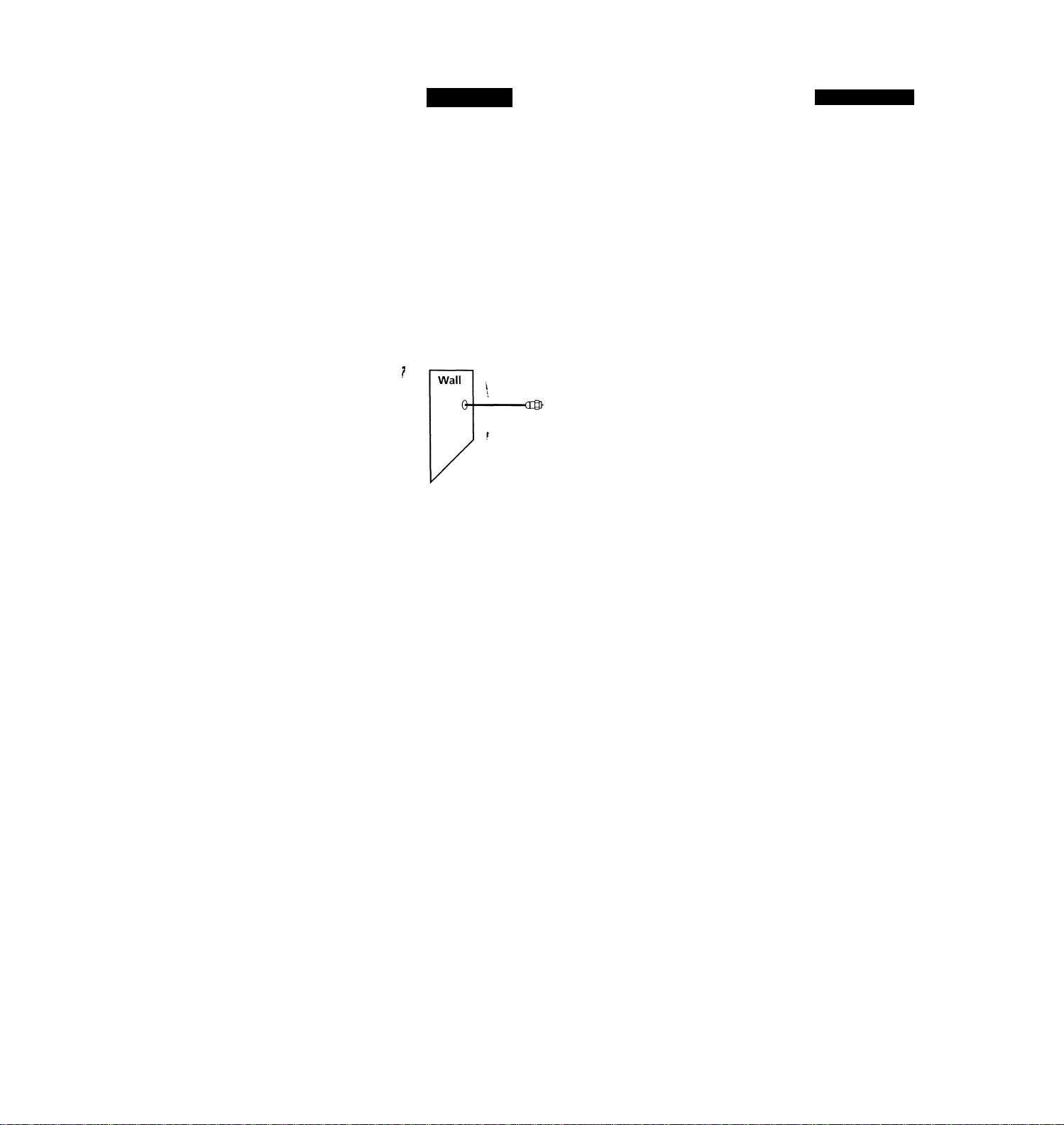
If you cannot connect your antenna cable to the VCR directly
If your antenna cable is a flat cable (300-ohm twin lead cable), attach an external
antenna connector (not supplied) so you can connect the cable to the VHF/UHF IN
connector. If you have separate cables for VHF and UHF antennas, you should use a
U/V band mixer (not supplied). For details, see page 44.
continued
Page 18

step 3: Hookups (continued)
Hookup 3:
1
VCR setup
Set the RF UNIT switch to
CH 3 or CH 4, whichever
channel is not used in your
area. If both are used, set
the switch to either channel.
For details, see page 43.
If you made A/V
connections (from page 9),
you can skip this step.
Press EASY SET UP on the
VCR. V
O The LANGUAGE menu appears. Change the
on-screen display language to Spanish
(ESPAÑOL) or French (FRANÇAIS) if desired,
and press the cursor stick (OK). For details, see
page 29.
© The CLOCK SET menu appears. Select AUTO
and press the cursor stick (OK). For details, see
page 30.
© The ZIP/POSTAL CODE menu appears. Push
the cursor stick to \ ! V ! ^ to enter the
ZIP / POSTAL CODE in your area and press the
cursor stick (OK). (You can also use the number
buttons to enter the ZIP/POSTAL CODE.)
O The CABLE BOX menu appears. Select OFF and
press the cursor stick (OK).
Use 4^1 to select
Then push |0K1
Push [easy set 1j^ to quit
lAUTO IMANUALI
Use [■♦•♦I t 0 se l ec t
Then push [OKI
Push [EASY SET~Ü^ to quit
ZIP / POSTAL CODE
Enter your ZIP/POSTAL
CODE us i ng |0-9|, o r If 4|
and 14--»I kevs,
then push lOKl
_________________
CABLE MOUSE
© The TUNER PRESET menu appears. Set
ANTENNA/CABLE to ANT and press the
cursor stick (OK). For details, see page 40.
Use 5^+lj^_se_l_ect
Push lEASY SET UP| to quit
ANTENNA / CABLE
Use to select
Then push |0K|
Push [easy SETU^ to qui
Page 19

© The AUTO PRESET
starts.
Normal display
Automatic clock setting
Once you've set up the VCR, it automatically sets the clock the first time you
turn off the VCR. After that, whenever you turn off the VCR, it checks the
time and adjusts the clock, even for Daylight Saving Time. The VCR sets the
clock by picking up a time signal provided by some TV channels.
If you want to use the timer to record right away, or if the channels in your
area do not carry time signals, set the clock manually. For details, see page
32.
continued
Page 20

step 3: Hookups (continued)
Hookup 4
Incompatible cable box with many scrambled
channels
Recommended use
Use this hookup if your cable company cannot supply a cable box that is
compatible with the VCR's cable box control feature, and your cable system
scrambles all or most channels.
What you can do with this hookup
• Record any channel by selecting the channel on the cable box
What you can't do
• Record with the cable box turned off
• Record one channel while watching another channel
• Select channels directly on the VCR
• Record programs with VCR Plus+
•.Use the GUIDE Plus-t- system
VCR
Cable box
Pages 20 to 22
Rear of TV
VHF/UHF
i^A Match the type of
connector on your
TV: A, B. or C.
VHF
B For connector
types B and C, no
UHF connection
UHF
is required.
VHF
© ©
UHF
-CO«
Page 21

Hookup 4:
1 Set the RF UNIT switchTo
2 Turn on your cable box.
3 Press EASY SET UP on the VCR.
VCR setup
CH 3 or CH 4, whichever
channel is not used in your
area. If both are used, set
the switch to either channel.
For details, see page 43.
If you made A/V
connections (from page 9),
you can skip this step.
O The LANGUAGE menu appears. Change the
on-screen display language to Spanish
(ESPAÑOL) or French (FRANÇAIS) if desired,
and press the cursor stick (OK). For details, see
page 29.
© The CLOCK SET menu appears. Select
MANUAL, press the cursor stick (OK) and set
the clock manually. For details, see page 32.
© The ZIP / POSTAL CODE menu appears. Push
the cursor stick tof‘/4'/'^"/"^to enter the
ZIP/POSTAL CODE in your area and press the
cursor stick (OK). (You can also use the number
buttons to enter the ZIP/POSTAL CODE.)
O The CABLE BOX menu appears. Select OFF and
press the cursor stick (OK).
ENGLISH
ESPAÑOL
Français |
Use |4- 4-| t o select
Then push [ok|
Push [easy SET~U^ to quit
I AUTO Manuali
Use K-»! to select
Then push |0K1
Push [easy SETYjf^
ZIP / postal CODE
F23^
Enter your ZIP/POSTAL
CODE us i ng |0-9l o r It 4'|
and (■♦•♦I key s
then push [ok]
CABLE BOX CONTROL
_________________
CABLE MOUSE
gaBBa
Ion Ioff
© The TUNER PRESET menu appears. Set
ANTENNA/CABLE to ANT and press the
cursor stick (OK). For details, see page 40.
Use 1-4--»I to select
Push lEASY SET UP| to qui
ANTENNA / CABLE
I ANT ICABLEI
Use |-4-■»! to select
Then push [0K|
Push (easy SETFjPÍ to qu
continued
Page 22

step 3: Hookups (continued)
O The AUTO PRESET
starts.
Automatic clock setting
To use the Auto Clock Set feature with this hookup, you need to manually
select a channel that carries a time signal:
Tune the cable box t^ channel that carries a time signal.
1
2
Select AUTO in the CLOCK SET menu to turn on the Auto Clock Set
feature.
3 Turn off the VCR. It automatically sets the clock and adjusts for
Daylight Saving Time by picking up the time signal.
If you want to use the timer to record right away, or if the channels in your
ar^a do not carry time signals, set the clock manually. For details, see page
32.
Ncrte
• To use the Auto Clock Set feature, leave the cable box on.
Normal display
Page 23

Hookup 5
DSS (Digital Satellite System) receiver
Recommended use ^
Use this hookup if you have a DSS receiver. It allows the VCR's cable box
control feature to control the channel on the DSS receiver, simplifying the
recording process. A list of compatible DSS receivers is on page 36.
DSS (Digital Satellite System) is a satellite broadcast that provides superior
digital-quality video and crisp digital-quality audio. A variety of program
packages are available through your program providers. It also has program
guides that are sorted by program categories.
What you can do with this hookup
• Record any channels using the VCR's cable box control^ feature to select
What you can't do
• Record with the DSS receiver turned off
• Record any channels from cable or an antenna
Pages 23 to 25
channels on the DSS receiver
(To record channels from cable or an antenna, turn off the cable box control
feature.)
Use a cable box
Record programs with VCR Plus+
Use the GUIDE Plus+ system
Rear of TV
Page 24

step 3: Hookups (continued)
Hookup 5:
1 Set the RF UNIT switch to
2 Turn on your DSS receiver.
3 Press EASY SET UP>9n the
VCR setup
CH 3 or CH 4, whichever
channel is not used in your
area.' If both are used, set
the switch to either channel.
For details, see page 43.
If you made A/V
connections (from page 9),
you can skip this step.
VCR.
O The LANGUAGE menu appears. Change the
on-screen display language to Spanish
(ESPAÑOL) or French (FRANÇAIS) if desired,
and press the cursor stick (OK). For details, see
page 29.
0 The CLOCK SET menu appears. Select
MANUAL, press the cursor stick (OK) and set
the clock manually. For details, see page 32.
© The ZIP/POSTAL CODE menu appears. Push
the cursor stick to ♦/4/4-/^ to enter the
ZIP/POSTAL CODE in your area and press the
cursor stick (OK). (You can also use the number
buttons to enter the ZIP/POSTAL CODE.)
O The CABLE BOX menu appears. Select ON. For
details, see page 34.
Use It 4-1 to select
Then push |ok|
Push IeASY SETTÌ^ to quit
I AUTO Manual!
Use |t-»I to select
Then push |ok|
Push [easy SETYj^ to qui
ZIP/POSTAL CODE
1123—1
Enter your ZIP/POSTAL
CODE us i ng |0-9|, o r (t t|
and |t--»| keys,
then push IokI
CABLE BOX CONTROL
■ II iri'l III 1
BOX CODE NO.
BOX OUTPUT CH
_______________
ON lOFF 1
CH3 1
Use It-t-l to select
Push IEASY SET UP| to quit
Page 25

o Enter your DSS receiver code number and push
the cursor stick to For details, see page 35.
© Set your DSS receiver
output channel (BOX
OUTPUT CH) to LINE
and press the cursor
¡SETUP
CABLE BOX CONTROL
1 BOX CODE NO.
1 BOX OUTPUT CH LINE L
CABLE MOUSE
aEBsa
ON lOFF 1
----------—
---------
CABLE MOUSE
ISEaSEHZBU
BOX OUTPUT CH
Enter your CABLE BOX
Code No. us i ng (0-9l keys
Refer to the Operating
Manual for the Code
SET UP is done
1
stick (OK).
Use [■»•■►I to select
1 BOX CH. Then push ® |
CABLE
Normal display
Note
To successfully record a program from the DSS receiver, proceed as follows;
- Leave the DSS receiver on all the time.
- Turn off the display (menu screen, channel number, etc.) of the DSS receiver.
- To record or receive locked channels, unlock the channel before the VCR starts
recording.
- To set pay-per-view programs in the timer setting, order the pay-per-view
program before the VCR starts recording.
- Some programs are copy protected. You cannot record these programs.
continued
Page 26

step 3: Hookups (continued)
Hookup 6
Incompatible cable box with only a few scrambled
channels, using an A/B switch
Recommended use
By using an A/B switch (not supplied), this hookup allows you to record
both scrambled and unscrambled channels conveniently
What you can do with this hookup
• Record any unscrambled channel by selecting the channel directly on the
• Record any scramble^^channel by selecting the channel on the cable box
What you can't do
• Record one scrambled channel while watching another channel (the A/B
VCR (the A/B switch is set to A)
(the A/B switch is set to B) ■
switch is set to B)
VCR
Pages 26 to 28
Rear of TV
VHF/UHF
- - A Match the type oh
VHF
connector on your
TV: A, B, or C.
VHF
B For connector
types B and C, no
UHF connection is
UHF
required.
4
■<13 WM#
UHF
------- ----
Page 27

Hookup 6:
1 Set the RF UNIT switch to
2 Set the A/B switch to “K!'
3 Press EASY SET UP on the
VCR setup
CH 3 or CH 4, whichever
channel is not used in your
area. If both are used, set
the switch to either channel.
For details, see page 43.
If you made A/V
connections (from page 9),
you can skip this step.
VCR.
O The LANGUAGE menu appears. Change the
on-screen display language to Spanish
(ESPAÑOL) or French (FRANÇAIS) if desired,
and press the cursor stick (OK). For details, see
page 29.
© The CLOCK SET menu appears. Select AUTO
and press the cursor stick (OK). For details, see
page 30.
© The ZIP/POSTAL CODE menu appears. Push
the cursor stick tof'/^/-^/*^to enter the
ZIP / POSTAL CODE in your area and press the
cursor stick (OK). (You can also use the number
buttons to enter the ZIP/POSTAL CODE.)
O The CABLE BOX menu appears. Select OFF and
press the cursor stick (OK).
Use ■»! to sel ec t
Then push |Ot^
Push [easy set UP| to quit
I AUTO ImanüâlI
Use |-^-»I to select
Then push |OKl
Push [easy set Tj^ to quit
ZIP / POSTAL CODE
BIB
Enter your ZIP/PQSTAL
CODE using |0^ qr [TTI
and I»•»■] keys,
then push lOKi
_________________
Use [■♦••»] to select
Push [EASY SET UP| to quit
continued
Page 28

step 3: Hookups (continued)
4 Preset the cable box output channel (usually 2, 3, or 4). For details, see
page 41.
O Press MENU and select TUNER PRESET.
Normal display
TIMER SET / CHECK
TUNER PRESET
CLOCK SET
LANGUAGE
CABLE BOX CONTROL
ADVANCED OPTIONS
SMARTFILE EDIT
Use |4' I to select a
i tem, then push |0K|
O Enter the cable box output channel. Set
MANUAL SET to ADD and press the cursor
stick (OK).
ANTENNA / CABLE|A^ ICABLEI
AUTO PRESET
MANUAL SET ADD ERASE
AFT
FINE TUNING
Sel ec t CH with |o^ . Push
|ENTER|.R^ to ADD/ERASE
OFF
ON
Automatic clock setting
Once you've set up the VCR, it automatically sets the clock the first time you
turn off the VCR. After that, whenever you turn off the VCR, it checks the
time and adjusts the clock, even for Daylight Saving Time. The VCR sets the
clock by picking up a time signal provided by some TV channels.
If you want to use the timer to record right away, or if the channels in your
area do not carry time signals, set the clock manually. For details, see page
32.
Note
• To use the Auto Clock Set feature, set the A / B switch to A.
Page 29

Selecting a
language
V
0 ®
- - - - - - -
r-
cm
Q
You can change the on-screen display
language.
1 «MENU
' CD
• CURSOR
PUSH OK
2
PUSH OK
Press MENU, then push the cursor stick to
♦ / to move the cursor to LANGUAGE
and press the cursor stick (OK).
When using the EASY SET UP procedure,
skip this step.
Push the cursor stick to ♦ / 4' to select ENGLISH, ESPAÑOL, or
FRANÇAIS, then press the cursor stick (OK).
O '0 0 a o
0 0 0
■© 0 0
o 0 0010
CD ’CD
FRANÇAIS
Use It ■»1 10 select an
item, then push lOKi
MENU
Page 30

Setting the dock
Using the Auto Clock Set
feature
Some TV and cable channels transmit
time signals with their broadcasts. Your
VCR can pick up this time signal to
automatically set the clock.
The Auto Clock Set feature works only if
a channel in your area is broadcasting a
time signal. If broadcasters in your area
are not yet sending time signals, set the
time manually (page 32).
Before you start... ^
• Turn on the VCR and the TV.
• Set the TV to the VCR channel (channel 3 or 4). If your TV is
connected to the VCR using A/V connections, set the TV to video
input.
• Press TV / VIDEO to display the VIDEO indicator in the display
window. \
• Press INPUT SELECT so that a channel number appears in the
display window.
MENU
Cursor stick
OK
PUSH OK
• CURSOR
Press MENU, then push the cursor stick to
'f / to move the cursor to CLOCK SET
and press the cursor stick (OK).
When using the EASY SET UP procedure,
skip this step.
Push the cursor stick to ^
■ / to select AUTO, then press the
cursor stick (OK).
I AUTO [MANUALI
Use to select
Then push [OK]
Push iMENUl to quit
Page 31

To activate the Auto Clock Set function, turn off the VCR.
The VCR automatically sets the clock by searching for a channel that
carries a time signal and sets your time zone and Daylight Saving
Time (if applicable).
Notes
* •
• The clock cannot be set automatically if you don't receive a channel that carries a
time signal in your area. If so, set the clock manually.
• If there are only a few channels in your area that carry time signals, setting the clock
automatically may take up to about 30 minutes.
• If you use Hookup 1 or 4, make sure you leave the cable bo^ on.
continued
Page 32

Setting the clock (continued)
Using Manual Clock Set
The GUIDE Plus-f system operates
according to the time signals transmitted
from certain TV stations. However,
wheYi you set CLOCK SET to MANUAL,
the manual timer.operates according to
the VCR's own clock, and the GUIDE
Plus+ timer operates according to the
time signals transmitted from certain TV
stations.
V
Press MENU, then push the cursor stick to
/ 'I' to move the cursor to CLOCK SET
and press the cursor stick (OK).
When using the EASY SET UP procedure,
skip this step.
PUSH Dk
CURSOR
PUSH OK
Push the cursor stick to 4" / ^ to select
MANUAL, then press the cursor stick
(OK).
Q (3D C3D
O ■© ® CD (p
® © ■© p p
© ® © C
CD © P fc
(01
y
Use to select
Then push (O^
Push iMENUl to quit
I 1 / 1 /
Use £3
cu rr ent MONTH
Then, pu
DAY
MENU
Cursor stick
OK
I AUTO iMANUALl
1998 THU 12;00AM|
to select
sh (3 to set
Push the cursor stick to “f / 4' fo set the
month.
Hi/ 1 / 1998 SUN 1 2 : 0QAM|
Use l-f 4’| to select
current MONTH
Then, push 0 to set
DAY
Page 33

• CURSOR
PUSH OK
Push the cursor stick to to highlight
the day and push the cursor stick to ^ / 4^
to set the day.
H 1 /16/1998 MON 12: OOAMi
Use l4’ 4'1 to select
current DAY
Then, push @ to set
YEAR
6
CURSOR
CURSOR
Set the year, hour and minutes in the same way as the day.
The day of the week is set automatically.
Press the cursor stick (OK) to start the clock.
Page 34

Setting up cable box control
(Skip this section if you are
using Hookup 2, 3, 4, or 6.)
Your VCR includes a cable box control
feature that allows the VCR to control
most brands of cable boxes/DSS
receivers via the Cable Mouse. With
cable box control, the VCR controls
channels on the cable box/DSS receiver
for timer recording. You can also use the
VCR's remote commander to change
channels on the cable box/DSS receiver
whenever the cable box/DSS receiver is turned on even if the VCR is
turned off. To use cable box control, you need to connect the Cable
Mouse (pages 11 and 23) and set the code number and output channel.
This VCR is programmed with codes necessary to control channel
selection on most brands of cable boxes at the time this VCR was
manufactured. It is possible that new cable boxes may be introduced
that cannof be controlled with this VCR's Cable Mouse. If you have a
cable box that is incompatible with this VCR, contact your cable
operator
box.
-7 they may be able to provide you with a compatible cable
'O (D ®
0 0 0
0 0 0
CD
0
CD CD
0
Q
Number
buttons
CH +/-
MENU
Cursor stick
OK
PUSH OK
PUSH OK
Press MENU, then push the cursor stick to
/ 4^ to move the cursor to CABLE BOX
CONTROL and press the cursor stick
(OK).
When using the EASY SET UP procedure,
skip this step.
Push the cursor stick to ^ / “► to select
ON, then push the cursor stick to
SSQDiS
mm
Use 10 select
Push |MET^ to quit
CABLE BOX CONTROL
Enter your CABLE BOX
Code No. using |0-9| keys
Refer to the Operating
Manual for the Code
~wn
Page 35

3 '© © '©
’© © ©
© © ©
©
• CURSOR
Press the number buttons to enter the
cable box/DSS receiver code number, then
push the cursor stick to 4'-
Find your cable box/DSS receiver code
number from the chart below.
CABLE BOX CONTROL
CABLE MOUSE
BOX CODE NO.
IBOXOLITPLrrCH
Use to select CABLE
BOX CH. Then push ^
Ion loFF I
• CURSOR
If you want to control a cable box, push the cursor stick to to
select the output channel for the cable box, then press the cursor
stick (OK). ^
If you want to control a DSS receiver, select LINE, then press the
PUSH OK
cursor stick (OK).
Cable box and DSS receiver brand and the corresponding code numbers
If more than one code number is listed, try entering them one by one, until
you come to the correct code for your equipment.
Cable box
brand
ABC 018, 022, 024, 028, 217
Antronix
Archer
BBT
Cable Star 067
Cabletenna 033
Cable time
Century
Citizen
Clyde Cablevision 097
Colour Voice 036, 042
Comb and 243, 244
Comtronics 051, 071
Decsat
Diamond
Eagle Comtronics
Code numbers
218
033, 050, 164, 218, 808
278
172, 388, 459
164
164, 326, 327
434
046
051
Cable box
brand
Eastern
Electricord . 089
Electus
Focus
Garrard
GC Electronics 027, 067, 341
GE 243, 244
GEC
Gemini
General Instrument
Hamlin
Hitachi
Jasco
Jerrold
Linsay 451
Code numbers
013,285
055
411
164
097
026, 068, 081
022, 287, 487
020, 031, 045, 270, 284 .
022
164, 326
014, 022, 025, 026, 035, 037,
058, 109, 287, 487
continued
Page 36

Setting up cable box control (continued)
Cable box
brand
Macom
Magnavox
Memorex
Code numbers
044
038, 043, 080
Oil
Movie Time 089, 167, 214
Northcoast
Novaplex
NSC
Oak
Panasonic
Paragon
Philips
325
629
074, 081, 167, 214
018, 030, 259
032, 118
Oil
036, 038, 039, 040, 041, 042,
071, 301
Pioneer
034, 155, 271, 544, 695
Popular Mechanics 411
Pulsar ^
Radio shack
RCA
Realistic f
Recoton
Regal
Regency
Rembrandt
Samsung
Scientific Atlanta
Seam
Sharp
Signal
Signature
SL Marx
Spectravision
Sprucer
Oil
808
032
218
411
031, 270, 284, 290
013
081
051, 155
017,019, 028, 288
521
324
051
022
051
069
032, 318
Standard Components 107, 166
Starcom
Stargate
014, 026, 058, 109
026, 051
Cable box
brand
STS
Sylvania
T-Cable Teletext
Tandy
Tatung
Teknica
TeleCaption
Teleservice
Texscan
TFC
Timeless
Tocom
Toshiba
Code numbers
167
0l2
. 116
269
108
157
232
292
012, 107
321
429
023, 024
Oil
Tudi 297
TV86 074
TV COM
Uniden
Unika
United Artists
United Cable
Universal
018, 030, 259
236
033,164, 218
018
014
033, 050, 067, 088, 089,164,
202, 218, 333
Videoway 261
Vidtech
Viewstar
255
038, 071,074,122, 222, 269,
300 ^
Zenith
Zentek
Wave Master
DSS receiver
brand
RCA
Sony
oil, 065, 536
411
576
Code numbers
577
650
¡6
Page 37

To ensure correct operation
• Place the Cable Mouse so that it hangs out over the cable box/DSS
receiver front.
• Do not place the cable box/DSS receiver on top of the VCR.
• Position the cable bax/DSS receiver away from the VCR.
• Point the remote commander at the VCR, not at the cable box/DSS
receiver.
: Signal flow
To check the cable box control setting
1 Press CH +/ - on the remote commander. Does the channel indicator
on the cable box/DSS receiver change? (Point the remote commander
at the VCR, not at the cable box/DSS receiver.)
2 Press all 10 number buttons (0 to 9) on the remote commander. Does
the channel indicator on the cable box/DSS receiver change?
If the answer to both 1 and 2 is "'yes,J' you have made the correct setting.
continued
Page 38

Setting up cable box control (continued)
If you cannot get your VCR to control the cable box/DSS receiver
• Check that the Cable Mouse is connected to the CABLE BOX CONTROL
jack on the VCR.
• Check the position of the Cable Mouse. i
• Place the cable box/DSS receiver and VCR away from each other. Do not
place the cable box/DSS receiver on top of the VCR.’
• Try the setup again making sure to use the correct control code. If the
cable box still does not respond, try the other codes that are listed.
If your cable box still does not operate with the Cable Mouse, contact your
cable company to see if they can provide you with a compatible cable box.
Note
• Make sure you turn off the VCR when you plug in or unplug the Cable Mouse. If
you unplug the Cable MoS^ and plug it in again, turn on the VCR before you use
the cable box/DSS receiver control feature.
Page 39

Presetting
channels
(Skip this section if you are
using cable box/DSS
receiver control feature.)
This VCR is capable of receiving VHP
1®
CD
■© ©
■©
(3D Cffi (
© CD'
© CD'
©
© o
©
©
J
b
CD
O
©1
channels 2 to 13, UHF channels 14 to 69
and unscrambled CATV channels 1 to
125. First, we recommend that you
preset the receivable channels in your
area using automatic presetting. Then, if
there are any unwanted channels, ,
disable them manually. If you have
decided which channels you wish to
preset, set them directly using manual
presetting.
Before you start...
• Turn on the VCR and the TV.
• Set the TV to the VCR channel (channel 3 or 4). If your TV is
connected to the VCR using A/V connections, set the TV to video
input.
• Press TV/VIDEO to display the VIDEO indicator in the display
window.
\
MENU
Cursor stick
OK
Presetting all receivable channels automatically
•MENU
1
Q
PUSH OK
Press MENU, then push the cursor stick to
♦ / 4' to move the cursor to TUNER
PRESET and press the cursor stick (OK).
When using the EASY SET UP procedure,
skip this step.
ANTENNA/CABLElANT |
1 AUTO PRESET
liMANUALSET
AFT
FINE TUNING
Select CH wi
■ado
ION
th |0-9|.
continued
OABLEl
erXseI
[off
Push
1
39
Page 40

Presetting channels (continued)
• CURSOR
PUSH OK
• CURSOR
•CURSOR
PUSH OK
To preset cable TV channels:
Push the cursor stick to 4—/to set
ANTENNA/CABLE to CABLE.
To preset VHP and UHF channels:
Push the cursor stick to to set
ANTENNA / CABLE to ANT.
Push the cursor stick to to select
AUTO PRESET then press the cursor stick
(OK).
All receivable channels are preset in
numerical sequence. When no more
receivable channels can be found,
AUTO PRESET
M/^NUAL SET
AFT
FINE TUNING
Use t o select____________an
i tern, then push [4--»|
ANTENNA/CABLE
AUTO PRESET
MANUAL SET
AFT
FINE TUNING
UselTSto select an
i t em, t hen pi
Biniiaaasii
ANTENNA / CABLE |ant
AUTO PRESET
MANUAL SET ADD
AFT
FINE TUNING
To start AUTO PRESET,
push |0K|
presetting stops and the picture from the
lowest numbered channel is displayed on
the TV screen.
Tip
When receiving a VHP, UHF, or CATV channel, the display changes as follows each
time you press DISPLAY.
ADD ERASE
ON
lADD
PN
iSh
ION
OFF
ERASE]
OFF 1
PABLEI
lERASEl
PFF 1
Remaining tape length and time counter
The bar indicator and pointer for searching a specific point
No display
Page 41

Presetting/disabling
channels manually
^0 (®
....... r
■© ■© ©
■© © ■©
’© © ©
CD © O
............
OB Q
CD'CD
a a
g
0
J
Number
buttons,
ENTER
CH +/-
B
MENU
Cursor stick
OK
1
Press MENU and select TUNER PRESET,
then press the cursor stick (OK).
PUSH OK
2 ■© ¡0 ®
© © ©
© © ©
® CD
To preset a channel:
1 Press the number buttons to enter the
channel number, then press ENTER.
2 Push the cursor stick to to set
MANUAL SET to ADD.
To disable a channel:
1 Press CH +/ - to select the channel
number.
2 Push the cursor stick to ^ ^ to set
MANUAL SET to ERASE.
• CURSOR Repeat step 2 to preset or disable channels as required, then press
the cursor stick (OK).
■Hi
■EES
ANTENNA / CABLElANT ~ ICABLEl
I AUTO PRESET
1 MANUAL SET
AFT ION
FINE TUNING
Select CH w i
lENTERlk-^l to
ANTENNA / CABLElANT ICABLEl
AUTO PRESET
AFT
FINE TUNING
Select CH wi th |o^ . Push
lENTERtR^ to ADD/ERASE
ANTENNA / CABLElANT ICABLEl
AUTO PRESET
MANUALSET
AFT ON
FINE TUNING
Se I ec t CH with |0^ . Push
lENTERlk-»! to ADD/ERASE
■add“
th |0-9|
ADD / ERASE j
ADD
ON
ADD ERASE
JoFF 1
. Push
lERASE]
ERASE
OFF
OFF
continued
Page 42

General setup information
Setting the RF unit
when connecting the VCR to the TV
using only the antenna cable, you must
set the RF UNIT switch on the rear of the
VCR so that the TV can receive the
correct signal from the VCR.
1 Set the RF UNIT switch on the rear of the VCR to CFi 3 or CH 4,
whichever channel is not used in your area. If both are used, set the
switch to either channel.
2 Press POWER to turn on the VCR.
3 Press TV/VIDEO to turn on the VIDEO indicator in the display
window. '
4 Press CHANNEL +/- to display a channel number in the display
window. Select an active channel number in your area.
5 Turn on your TV and set it to the channel you selected in step 1
(channel 3 or 4).
The selected TV channel broadcast appears on the TV screen. If the
channels change when you press CHANNEL +/ - on the VCR, you
have made the correct setting.
Whenever you use the VCR, set the TV to the channel selected in step 1.
POWER
0
■© © © CD 'CB‘© '© '© CD O
■ 0
CD © O ^
(D C2D
TV
CHAJ^NEL +/-
POWER
TV/VIDEO
■ ©
continued
43
Page 43

Presetting channels (continued)
If the picture is not clear
Normally, the Auto Fine Tuning (AFT)
function automatically tunes in channels
clearly. If, however, the picture of a
channel is not clear, you can also use the
manual tuning function.
Press MENU and select TUNER PRESET,
then press the cursor stick (OK).
2 O ® ® Press the number buttons to select the
® ® © channel you want to fine-tune, then press
'© ® ®
0 CD
ENTER.
■"I
0
CD
J ~
CM
cm
Q
Number
’© ’© ©
'© '© '©
© © ©
© O
CD CD
buttons,
ENTER
MENU
Cursor stick
OK
■ESS
ANTENNA / CABLElANT '
1 AUTO PRESET
1 MANUALSET
AFT ION lOFF 1
FINE TUNING
Select CH wi th b-9!
IenterIR^ to ADD/ERASE |
AFT
FINE TUNING
Select CH with |o^ . Push
IENTEN-R^ 10 ADD / ERASE
■■ADD
IcableI
IeraseI
Push
3 • CURSOR Push the cursor stick to / ♦ to select
FINE TUNING.
The fine tuning meter appears.
PUSH OK
• CURSOR
4
Push the cursor stick to to adjust
to a clearer picture.
Note that the AFT setting switches to OFF.
PUSH OK
ANTENNA / CABLEIaT^ |CABLE|
AUTO PRESET
MANUAL SET
AFT
FINE TUNING
Push |»-»|
ANTENNA / CABLElANT |CABLE|
AUTO PRESET
MANUAL SET
AFT
[ADD
pN
ADD
ON
[ERASE
lOFF
Push I ■ »•»I
Page 44

General setup information (continued)
Attaching the external
antenna connector
when using a 300-ohm twin lead cable
for VHF/UHF antenna, use the EAC-32
anten'na connector (not supplied) to
connect the antenna to the VCR,
1 Loosen the screws on the antenna connector.
2 Wind the twin leads around the screws on the antenna connector.
3 Retighten the screws.
Attaching a UHFA/HF band
mixer
when using both 75-ohm coaxial cable
and 300-ohm twin lead cable for VHP /
UHF antenna, use the EAC-66 UPiF /
VHF band ^parator/mixer (not
supplied) to connect the antenna to the
VCR.
300-ohm twin
lead cable
EAC-32 antenna
connector
(not supplied)
V
300-ohm twin
lead cable
EAC-66
UHF/VHF
band
separator/
mixer (not
supplied)
75-ohm coaxial
cable
1 Loosen the screws on the mixer.
2 Wind the twin leads around the screws on the mixer.
3 Retighten the screws.
4 Connect the 75-ohm coaxial cable to the mixer.
Page 45

Index to parts and controls
Refer to the pages indicated in parentheses ( ) for details.
Front panel
POWER switch/indicator (6, 43)
ffl
SmartFile sensor
SMARTFILE indicator
INPUT SEFECT button (30)
a
[H EASY SET UP button (12,15, 18, 21,
24, 27)
Tape compartment
[7] CHANNEL/TRACKING+/-
buttons (43)
g] REJECT button
[9] t> PLAY button
|T0| JOG button/indicator
[TT] # REC (record) button
M »STOPbutton
[13| Shuttle ring
|j3 II PAUSE button
[i^ ►► FF (fast forward) button
|16| ◄◄ REW (rewind) button
M COMMAND MODE button (6)
M OK button (29)
M CURSOR f button
M SMARTFILE button
1^ Remote sensor (5)
il LINE-2 IN VIDEO / AUDIO L / R
jacks
i
continued
45
Page 46

Index to parts and controls (continued)
Display window
^_;0^^BTEREOIS^IS^P LJPlVI^dlAPCr
in Timer indicator
i^ Child Lock indicator
[3l STEREO indicator
m SAP ($econd Audio Program)
indicator
Î5l Tape $peed indicator
[6] VIDEO indicator (30, 43)
in APC (Adaptive Picture Control)
indicator
m [2] ® s] [5]
m m
_N/I N/l ■ M M ■ N^l M
Ml'® ® -® ® -® ®
M
V
[8] BLANK indicator
|~9l Tracking indicator
[TOl Line/channel indicator (30)
[Til Time counter/ clock
51 Command mode indicator (6)
in Remaining time indicator
[14| Tape / recording indicator
mmm
M M N¿1
I® I® I®
Page 47

Rear panel
rri AC power cord (8)
[2] S LINK (CONTROL S IN) jack (10)
[3] CABLE BOX CONTROL
(CONTROL S OUT) jack (11, 23)
g] LINE-1 IN AUDIO L / R / VIDEO
jacks (23)
[5] CPD (Control and Program Data) IN
jack
G-Link jack"^
VHF/UHF IN connector (11, 14, 17,
20, 23, 26)
VHF/UHF OUT connector (11, 14,
17, 20, 23, 26)
RF (Radio Frequency) UNIT switch
(43)
LINE OUT AUDIO L / R / VIDEO
jacks (9)
continued
This jack is provided for future expected functions.
Page 48

Index to parts and controls (continued)
Remote commander
E
a
m
M
o
M
± EJECT button
Number buttons (6, 35, 41)
SET button
ENTER button (41)
SMARTFILE button
# REC (record) button
Blue button
GUIDE button
Green button
MM REW (rewind) button
►► FF (fast forward) button
O PLAY button
■ STOP button
Shuttle ring
18
Page 49

lii [t3/[VIDE^ switch (5, 6)
m COMMAND MODE switch (6)
EZ] POWER switch (6, 43)
M VCR Plus+button
m TV/VIDEO button (6, 30,43)
US CLEAR button
M DISPLAY button,(40)
m CH (channel) + /- buttons (6, 37, 41)
|23| VOL (volume) + /- buttons (6)
M MENU button (29)
[2^ Cursor stick (29)
OK
m II PAUSE button
|27] JOG button / indicator
continued
Page 50

ndex to parts and controls (continued)
demote commander, with top cover opened
m SP (Standard Play)/EP (Extra Play)
button 1
[2] INFO (information) button
[3] AUDIO MONITOR button
H COUNTER RESET button
[5] QUICK TIMER button
[6] !◄◄ / ►►) INDEX SEARCH buttons
H] SMART CUE button
[U INPUT SELECT button (30).
d] TV / VIDEO button (6, 30, 43)
m COUNTER/REMAIN button
iH] CLEAR button
M DISPLAY button (40)
IT3I CH (channel) +/- buttons (6, 37, 41)
Il4l VOL (volume) + /- buttons (6)
[15] Receiver operation buttons
RECEIVER VOL (volume) +/buttons (5)
MUTING button (5)
Page 51

Page 52

Index
A. B
Accessories supplied 4
AFT (Auto Fine Tuning)
Antenna hookup 17
Audio/video (A/V)
hookup 9
Auto Clock Set feature
Disabling channels 41
42
DSS (Digital Satellite System)
23
E, F, G, H, I, J, K
30
Easy Set Up 12,15,18, 21,
24, 27
Cable Box Control
cable box code number
chart 35
setting 34
Cable hookup 11
Cable Mouse 34
Clock setting 30
Connecting
cable TV 11
external antenna
connectoiij 44
UHF/VHFband
mixer 44
L, M, N, O
Language selecting 29
P, Q^ R
Presetting channels 39
S, T, U, V, W, X, Y, Z
S-Link™ 10
Sony Corporation Printed in Malaysia
 Loading...