

Page 1
i:I
H MECHANISM
OPERATION MANUAL
S
Page 2
Contents
1. Main parts layout diagram .......................................................................................... 3
2. Tape path .................................................................................................................... 4
3. Cassette IN --_ Loading --_ Stop ................................................................................. 5
4. Stop --_ Playback ...................................................................................................... 11
5. Stop --_ Power OFF .................................................................................................. 13
6. Playback --_ CUE ..................................................................................................... 15
7. Playback --_ REV ..................................................................................................... 17
8. Stop --_ Fast forward (FF) ........................................................................................ 19
9. Stop --_ Rewind (REW) ............................................................................................ 23
10. Stop --_ Unloading --_ Eject ...................................................................................... 27
1-16
Page 3
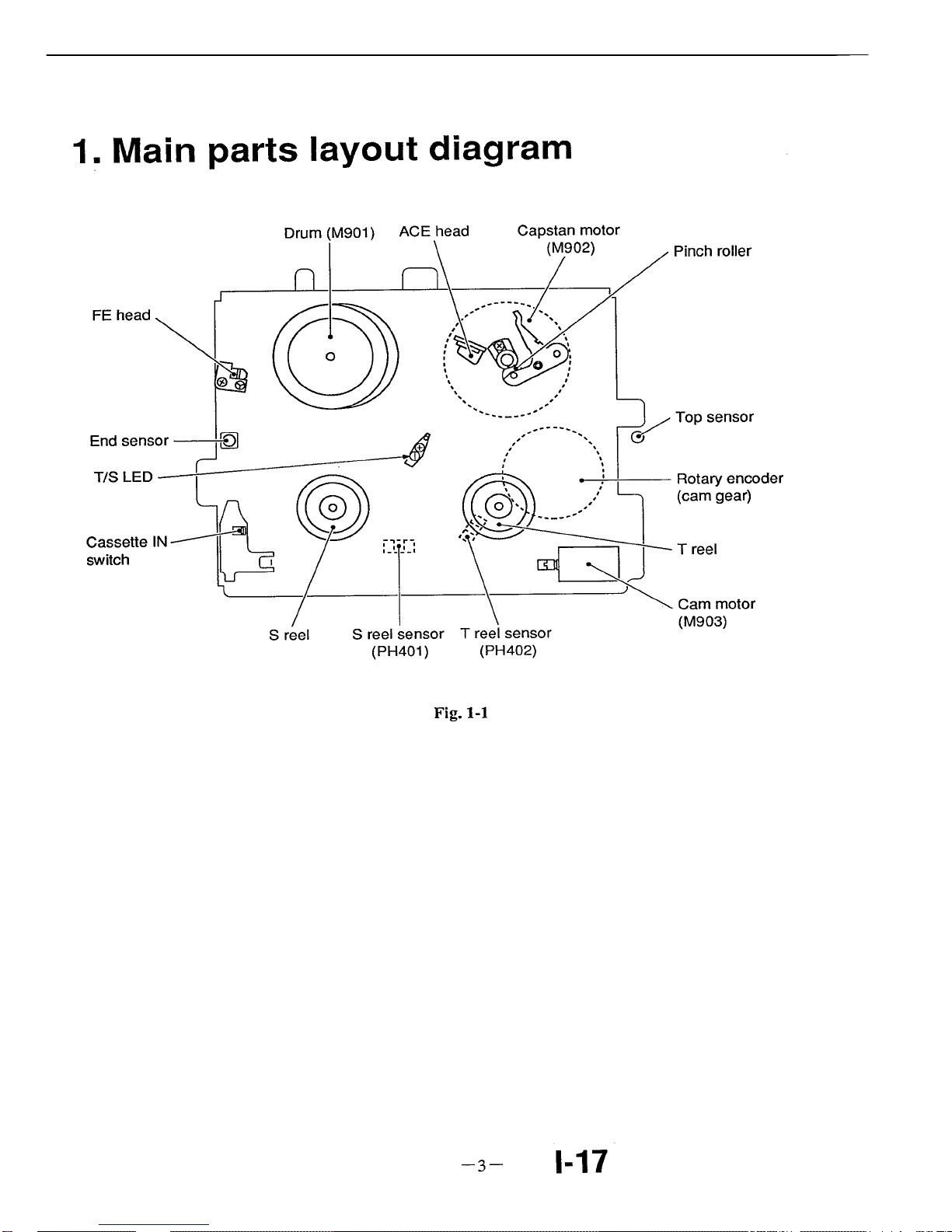
1. Main parts layout diagram
FE head
End sensor--
T/S LED -_
Cassette IN
switch _ /
S reel
Pinch roller
T
S reel sensor
(PH401)
Top sensor
Rotary
encoder
ot.._.Q____.__.........,I,_ L__ (cam gear>
_ [_ _ I_ "_" T reel
\ _ Cam motor
', (M903)
T reel sensor
(PH402)
Fig. 1-1
3 1-17
Page 4
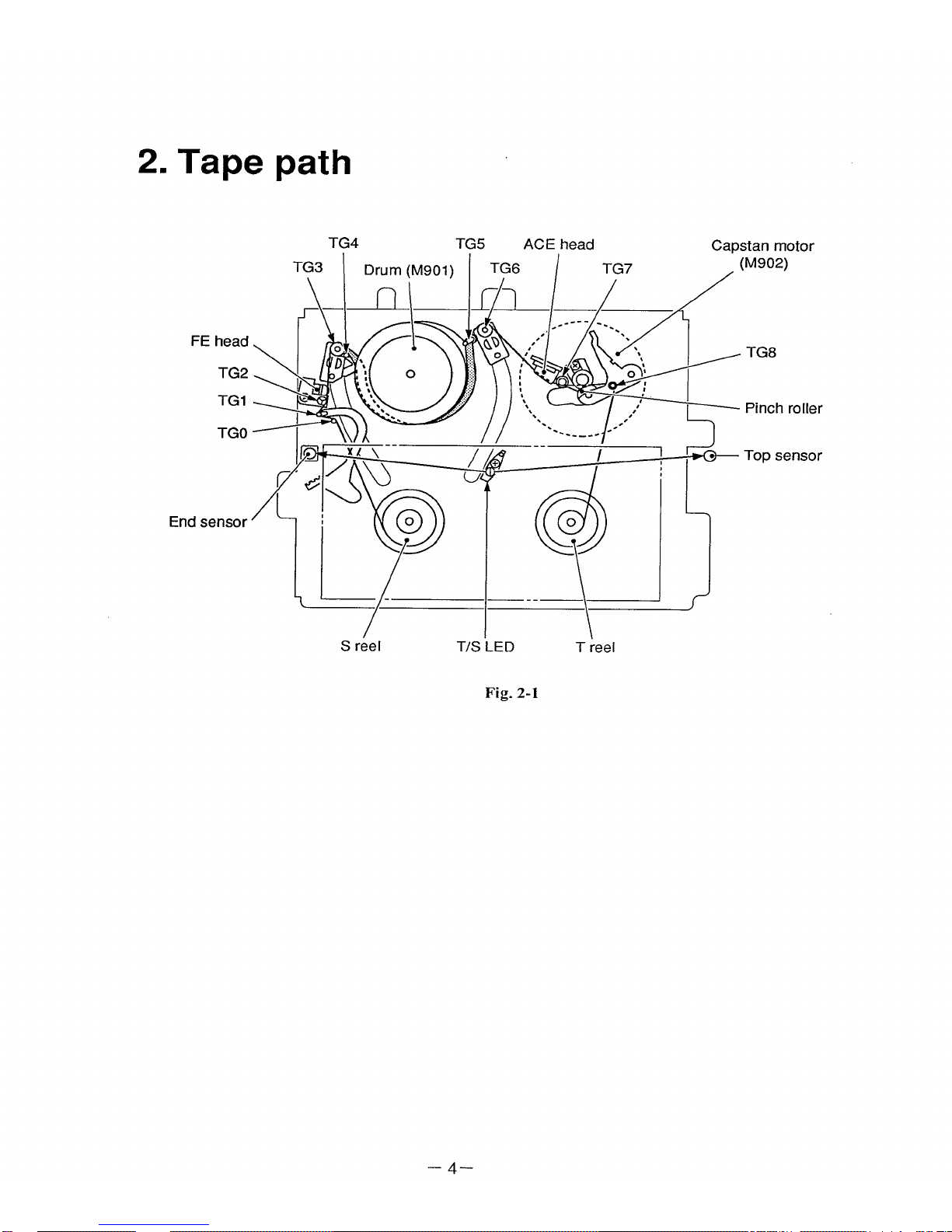
2. Tape path
TG4 TG5 ACE head Capstan motor
S reel T/S LED T reel
Fig. 2-1
4
Page 5
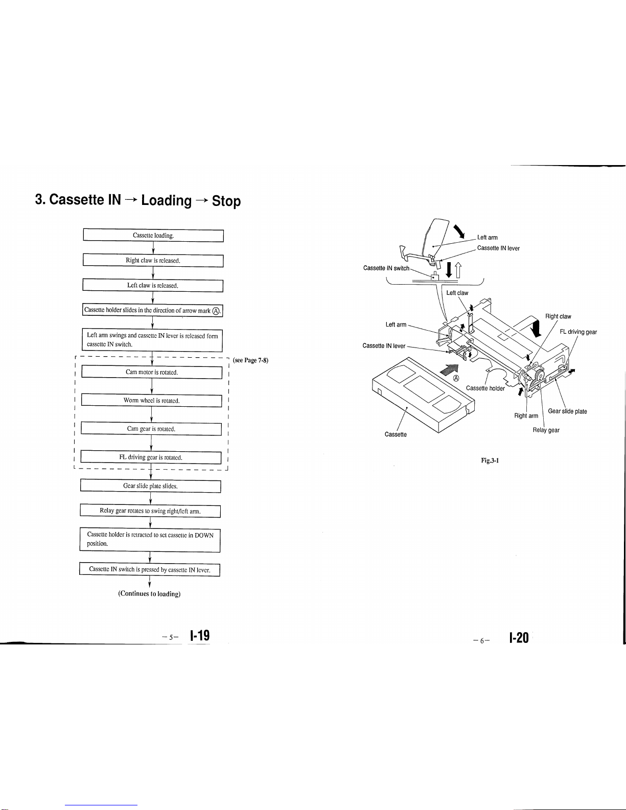
3. Cassette IN -- Loading--- Stop
Cassette loading.
Right claw is released.
Left claw is released.
I
I
5
ICassottchol_e,s,_cs,nthe_,rcc,ono_a_owma_k0.r
Left arm swings and cassette IN lever is released form I
|
cassette IN switch.
I
I Cam motor is rotated. [
1
[ Worm wheel is rotated. [
[ Cam gear is rotated. [
I FL driving gear is rotated. [
i Gear slide plate slides.
I Relay gear rotates to swing right/left arm.
t
Cassette holder is retracted to set cassette in DOWN
position.
Cassette IN switch is pressed by cassette IN lever.
(Continues to loading)
(see Page 7-8)
Cassette
Cassette IN switch
Leftclaw
IN lever
Leftarm
Cassette IN levi
Cassette holder
Cassette
Fig.3-1
Right claw
FLdriving gear
Right arm
Gear slide plate
Relay gear
1-20
-_- 1-19 6
Page 6
€
FL driving
gearisrotated.
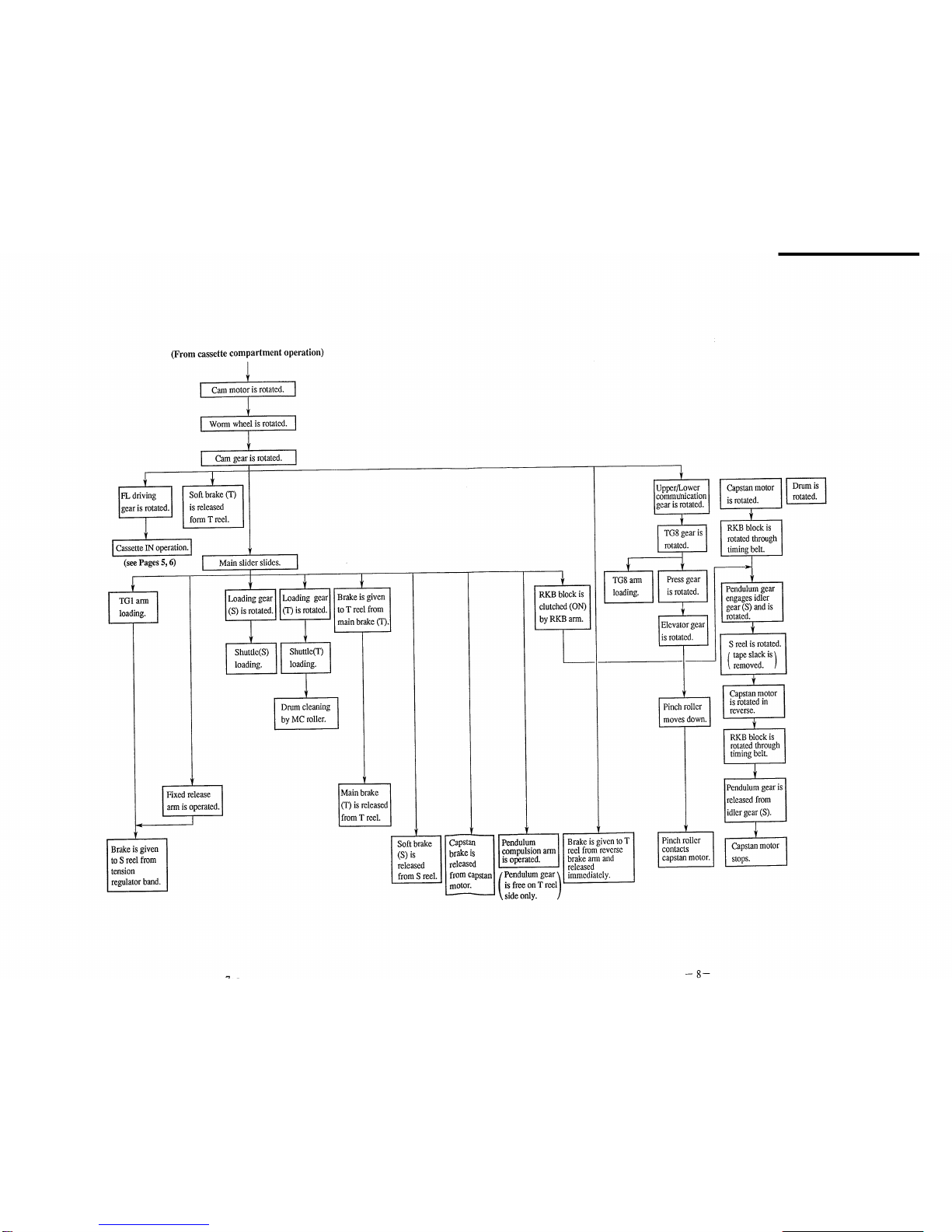
ICassetteiNoperation,i
(seePages 5, 6)
TGI armloading.
(From cassette compartment operation)
I Cammotor is rotated. I
[ Wormwheel is rotated. I
[ Cam gearis rotated. [
Softbrake (T) i
is released I
form T reel. [
I
Main slider slides.
ILoading gear
(S) isrotated.
I
(T) is rotated.[I to T reel from I
1 [ main brake(T).[
I ixed releasearm isoperated.
I
Brakeisgiven
to S reel from
tension
regulatorband.
Shuttle(S)loading.
I Shuttle(T)
loading.
I Dmm cleaningby MC roller.
Main brake
(T) is released
fromTreel.
Soft brake
(S)is
released
from S reel.
€
RKB block is
clutched(ON)
by RKB arm.
f !
["Capstan I [Pendulum
[brakeis I compulsionarm
Ireleased I isoperated.
[fromcapstanI[Pendulumgear'_
| is free on T reelI
\ side only.
€
TG8arm
loading.
Upper/Lower
commu'nication
gear is rotated.
t
i
TG8gear is I
I
rotated.
] :°22
Elevator gear
is rotated.
L
Pinchroller ]
moves down.
Brake is given toT
reel fromreverse
brake arm and
released
immediately.
Pinch roller
contacts
capstanmotor.
I II
RKB block is [
1
rotatedthrough
I
timingbelt.
Pendulumgear
engages idler
gear(S) and is
rotated.
S reel is rotated.
tape slack is /
removed. !
Capstan motor
is rotated in
reverse.
I RKBblockis ]
rotated through
timingbelt.
Pendulumgear is l
releasedfrom
idler gear(S).
l apstan motor
stops.
Drum is
rotated.
I
Page 7

Pinch roller moves Capstan shaft _ Pinch arm moves in the direction of
down in the direction _ _ / arrow mark_ and contacts capstan
ofarrowmarkt_..._7/_'_...._ L shaft. /
H _C_, _ "_ 9!,_7_--_ Capstan shaft
t_,/L I "_ /1 _ _ h'_'_ "-pinch r°ller
"" _r--_ll ,Jill _ _ _'_,_11 An opening(_ is
un n given between
Elevator gear ,-----F.L_._'\" f' _,./_ _,/,_'\ "_ '-_ pinch rollor and
_" _ \Press ear _Y_/_ \Pressgear pinch block by
" g ""_ / ..... _- press gearcam.
O Press.gea! andele.vato[ gear // _ Pinch'rolleris pressed in the direction
are ro_a_eei_tne direction or // ofarrow marki} by the tension of spring.
arrow mark U. ,/ -
Pinch block moves in the direction of
arrow mark _)through press gear cam.
Fig,3-2
Main slider moves in the direction of arrow mark O,
and RKB arm pushed up by step (_)moves in the
direction ofarrow mark I_).
_ Mainslider
?
arm
brock
,Timing belt
Pendulum g
Pendulum gear
RKB brock
I
!_ RKB arm moves in the direction of
arrow mark e, then RKB block moves
in the direction of arrow mark _) to
change the mesh of pendulum gear.
Timing belt
Fig.3-3
Shuttle (T)
Drum (M901)
TG1 arm
Shuttle (S)
Tension regulator
band
Fixed release arm
Soft brake (S)
Pendulum Capstan motor(M902)
compulsion (Capstan shaft)
arm
TG8 arm Pinch roller
MC roller MC arm
Upper/Lower
communication
gear
FLdriving gear
Cam gear
Cam
(M903)
S reel T reel
Pendulum gear
Idler gear (S) Neutrality arm
Capstan motor
(M902)
/
Loading gear (T)
Capstan brake
Idler gear (S)
Worm wheel
Drum (M901)
_r!__,
S reel
gear
Pinch arm
Fig.3-4
gear
gear
driving gear
Upper/Lower
communication
gear
RVS brake arm
Soft brake (T)
Main brake (T)
Cam motor
(M903)
Loadinggear (S)
Main slider
Timing belt
_____ Fixed
release arm
- - J4
Page 8

4. Stop --* Playback
ID'_m'sr°t_'_n_"I l
Press PLAY button. [
Capstan motor is rotated.
RKB block is rotated through I
timing belt (clutch ON).
Pendulum gear is meshed with
idler gear (T) and rotated.
T reel is rotated.
I
f
--11--
,: Drum
M901)
Capstan motor (M902) , 1
(Capstanshaft)
J
RKBbrock
T reel
Idlergear (T)
.._...j Pinchroller
Pendulum
compulsionarm
Capstan motor
RKBbrock
T re/_el
(M_02)
/
Idlergear (T)
Pendulumgear
Idler gear (S)
Tensionwheel
Timing belt
Fig. 4-1
Page 9

5. Stop --+Power OFF
I Soft brake(T)
is operated,
' Presspower button.
I Cam motor is rotated. }
[ Wormwheelisrotated[
[ Camgear is rotated. [
Upper/Lower
communicationgearis
rotated.
+
[ TG8gear is rotated, ]
I Pressgearisr°'ate_,i
Elevatorgear is rotated.
'_ If power is ON, it turns OFF
automatically about 5 minutes later.
I _ai_s,i_er_._o_-I
ainbrake s 'IIRKOp e,,e isI en°u,um
is operated. I compulsionarm
[is operated,
_ .....
Neutralityarm
is operated.
Fixedreleasearm is
operated,
+
Tensionregulatorband I
i
iensionbecomesweakto
ImakeS reelbrake weak.
Pinch-block [
movesinthe
directionof
arrowmark
andpinch
mileris
releasedfrom
capstanshaft.
1
Brakeis given [RKBblock ]
toS/I" reel. movesdown.
t
[
RKBblock becomesfree. I
Pendulumgearis releasedfrom Treel. ]
Capstan shaft
• Pinch block is operated and pinch roller
moves in the direction ofarrow mark O
until it is released from capstan shaft. ,,_ \
Pinch brock pin J_
./
Press gear cam/
j Pinch block
O Press gear is rotated in the direction of arrow mark O
and pinch block pin pushed to pressgear cam is
released from cam while pinch block moves in the
direction of arrow mark !_.
Fig. 5-2
Tension regulator
band
Fixed release arm
S reel
Capstan motor (M902) Elevator gear
Drum !M901) (Capsta_n shaft) Pinch roller/., Pinch arm
Main brake (S) RKI3brock Mainbrake (T)
Pendulum compulsion Neutralityarm
arm
_'ig.s-1
Capstan motor _
Upper/Lower
commt
gear
Cam
Cam motor
(M903)
Capstan brake Drum (M901)
R
Worm wheel Pendulum gear
Idler gear (T) RKB arm
Main slider
Fixed release
arm
J7 -13- -14- J8
Page 10

6. Playback CUE
Drum is rotating. I
I
Capstan motor is rotated at I
high speed.
I
,1
RKB block is rotated
through timing belt.
(clutch ON)
Pendulum gear and idler gear I
!
I
(T) are rotated at high speed. I
IT reel is rotated at high speed. I / Pinch roller is rotated
I i
L
at high speed.
•_ Difference from (Stop -" Playback)
(!) Capstan motor is rotating at high speed.
(g) Pendulum gear is meshed with
idler gear (T) from the beginning.
1
RKBbrock
RKBbrock
T reel
Drum(M901) Capstan motor (M902)
(Capstan shaft)
Pinch roller
Pendulumgear Treel
Idlergear (S) Idlergear (T)
Capstan motor
(Mi02)
Idlergear (T) Pendulum gear
Tension
/ wheel
___ Timing belt
Fig. 6-1
Page 11

7. Playback ---,REW
Cam motor is rotated. [
[ Worm wheel is rotated. ]
[ Cam gear is rotated. ]
I
reverse brake arm.
l Fixed release
arm is operated.
Brake is given to T reel by [
TG1 tension )
becomes weak.
Brake is given
to S reel by
soft brake (S).
Main slider slides.
Pendulum I
compulsion [
arm is operated. [
Pendulum
gear is free on
S reel only.
Drum is rotating.
I
Brake is given to
capstan motor by
capstan brake.
I
S winding arm is
operated to slightly
rotate S reel.
Capstan motor is rotated
in reverse at high speed.
S winding\
arm
Mainsliderj
S reel
When main slider moves in the direction of
arrow mark ®, S winding arm pressed by
main slider cam moves inthe direction of
arrow mark _ andS reel is rotateda little
in the direction of arrow mark.
RKB block is rotated
through timing belt.
(clutch ON)
"i
Pendulum gear is
meshed with idler gear
(S) and rotated.
S reel is rotated in
reverse at high speed.
_r
Pinch roller is
rotated in
reverse at high
speed.
Fig. 7-1
Drum
Fixed
arm
RKB
Pendulum
compulsion arm
Capstan motor (M902)
(Capstan shaft)
TG1 arm
S reel Pendulum gear Treel
Soft brake (S) Idler gear (S) RKB brock
Capstan brake
/ Tension wheel
Capstan motor (M902)
Cam motor
(M903)
Pendulumgear
Idler g_ear(S)
S reel
Fig. 7-2
roller
Elevator gear
gear
TG8 gear
Upper/Lower
communication
gear
RVS brake arm
-- Cam motor
(M903)
Main slider
_gbelt
release
arm
Jll J12
Page 12

8. Stop --, Fastfoward (FF)
•_ When this operation is mode
beforecassette tape is loaded for
playback, CUE mode is started
to readtape signaland then tape
is set in fast forwardmode.
Brakeis given to
T reel by soft
brake (T).
Upper/Lower
communication
gear is rotated.
TG8 gear is
rotated.
Pressgear is
rotated.
Pinch roller is
released from
capstan shaft.
I Cam motor is rotated. [
I Worm wheel is rotated. I
I Cam gear is rotated. I
I Main slider slides. [
Fixed release
arm is operated
to make TG1
arm tension
weak.
Brake is given
to capstan motor
by capstan
brake.
v
Capstan brake is
released from
capstan motor.
Brake is given [
to S reel by ]
main brake (S).]
Main brake (S)
is released
from S reel.
Brakeis given I
to T reel by [
main brake if).]
Main brake (T)
isreleased
form T reel.
Drumis rotating. ]
r
Pendulum
compulsionarm
is operated.
Neutrality arm ]
is operated.
,f
I r e everlslides.
I
Pendulumgear is locked )
inthe center between
S reel and T reel.
Neutrality arm is ]
operated again.
I
Pendulum
compulsion arm
is operated.
Pendulumgear is free on
S reel or T reel. )
I
RKBblock is
set in clutch
OFFby RKB
arm.
ICapstan motor is rotatedat [
high speed.
RKB block is rotated
through timing belt.
Pendulum gearis meshed
with idler gear (T) and
rotated.
T reelis rotated at high
speed.
Page 13

Pendulum
compulsion
arm
Drum (M901)
\
Capstan motor (M902)
TG8 gear (Capstan shaft) Pinch roller
Mainbrake (S)
Fixed release
arm
S
Pendulum gear T reel
RKB brock Idler (T)
Upper/Lower
communication
gear
Cam gear
RKB brock
Cam motor
(M903)
Capstan motor
(M902)
Worm wheel
T reel
Capstan brake Drum (M901)
Tension wheel
Trigger lever RKB arm
Pendulum gear Idler(
Fig. 8-1
gear
Pinch block
Press gear
Upper/Lower
_mmunication
gear
Neutrality arm
Mainbrake (T)
brake (T)
Cam motor
(M903)
Main slider
Timing belt
Main brake (S)
Fixed release
arm
J15 J16
Page 14

I
9. Stop -_ Rewind(REW)
T reelby soft II
brake (T). 11
I
•_ When this operation is mode l
before cassette tape is loaded for
I
playback, REV mode is started
to read tape signal and then tape
I
is set in rewind mode. I
I
Upper/Lower
communication
gear is rotated.
TG8 gear is
rotated.
Press gear is
rotated.
Fixed release
arm is operated
to make TG1
arm tension
weak.
Pinch roller is
released from
capstan shaft.
I
Brake is given
to capstan motor
by capstan
brake.
Cammotor is rotated.
Worm wheel is rotated.
1
Cam gear is rotated.
Main slider slides.
I
I
I
I
I
Brakeis given
to S reel by
main brake (S).
Capstan brake is [
released from [
capstan motor. [
,f
Main brake (S)
is released
from S reel.
I
Brake is given
toT reel by
main brake (T).
I
Main brake (T) [
1
is released
form T reel.
Drum is rotating.
Triggerlever
slides.
I
I
I
Neutralityarm
is operated.
r
Neutrality arm is
operated again.
I
_f
IPendulum [
compulsion ann
is operated.
Pendulumgear is locked \
)
in the center between
S reel and T reel.
Pendulum [
compulsion ann
is operated.
Pendulum gearis free on )S reelor T reel.
RKBblock is
setin clutch
OFF by RKB
alT0.
I
Capstan Motor is rotated
in reverse at high speed.
RKB block is rotated
throughtiming belt.
Pendulum gearis meshed
with idler gear (S) and
rotated.
S reel is rotated inreverse at high speed.
!
I
q
q
q
Page 15

Pendulum
compulsion
arm
Drum (M901)
\
Main brake (S)
Fixed release.
arm
S reel
Idler gear (S)
Capstan motor
(M902)
Upper/Lower
communication
gear
Cam,
RKB brock
Cam motor
(M903)
Worm wheel
Idler gear (T)
Capstan motor (M902)
(Capstan shaft)
TG8 gear Pinch roller
RKBbrock T reel
Pendulum gear
Capstan brake Drum (M901)
Tension wheel
Pendulum gear RKBarm
Idler _ear (S) S reel
Fig. 9-1
gear
Pinch block
Press gear
Upper/Lower
)mmunication
gear
LJtralityarm
Main brake (T)
Soft brake (T)
Cam motor
(M903)
slider
Timing belt
Trigger lever
Main brake (S)
Fixed release
arm
Page 16

!l'!_ip,
10. Stop -* Unloading Eject
Brakeis given
to capstan
motor by
capstanbrake.
S winding arm is
operated to rotate
S reel a little.
I am motor is rotated. [
I wormwheelisrotated.[
I am ea s otat I
[ Main slider slides. [
I
Brake is given[ Fiaxed
to S reelby [ release arm
softbrake (S). ! is operated.
TG1 arm [
unloading.
Tension regulator
band releases the
IBrakeis given
to T reel by
main brake (T).
brake from S reel.
Drum is rotating. I
Main brake (T)
]is released from
IT reel.
I Loading gear
(T)is rotated.
1
,I
Loading gear I
(S) is rotated.I
__3
Shuttle(S)
unloading.
Shuttle (T)
unloading.
k rum
cleaning by
MC roller.
Pendulum [Reverse brake
compulsion [arm gives
arm _s operated, ibrake to T reel
Pendulum gear \ /andis released
is free on S reel | [immediately.
only. /
RKBblock is
set in clutch
OFF by RKB
arm.
Upper/Lower [
communication gear is [
rotated. I
I
[Press gear is rotated. I
I
Pinch rolleris [Elevator gear is
released from Irotated.1
capstan motor.
IPinch roller moves up. I
r
I C_pa_e7mOtOris .I
RKBblock is
rotated through
timing belt.
(clutch ON)
Pendulum gear is
meshedwith idler
gear (S) and rotated.
( Tape is wound )
into cassette.
,l
[Capstan motor stops. I
IFL driving[ / Brakeis [
gearis givento [
rotated. T reelby [
softbrake[
(T). [
I oC;ratiUoenOUT1
(seePage 31, 32)
II
Page 17

Shuttle (S)
TG1 arm
Pendulum
compulsion Capstan motor (M902)
arm MC arm (Capstan shaft)
Shuttle (T) TG8 arm Pinch roller
Elevator gear
Pinch arm
Press gear
Tension regulator
band
Fixed releas,
arm
S reel Pendulum arm T reel
Soft brake (S) Idlergear (S) RKB brock
gear
Upper/Lower
communication
gear
FL driving gear
RVS brake arm
Soft brake (T)
Main brake (T)
Cam motor
(M903)
Upper/Lower
communication
gear
C
FL driving gear
Cam gear -_
J
Cam motor
(M903)
Capstan motor Shuttle (T)
(M902)
\
Capstan brake Drum (M901)
/
Worm wheel RKB arm
Shuttle (S)
i
Main slider
Idler gear (S)
\
Fixed release
arm
S reel
Fig. 10-1
0 Mainslider moves in the direction
of arrow mark 0 and RKB arm is
pushed up in the direction of
arrow mark • by step@.
Main slider
,O RKBarm
RKB brock
Pendulumgear
belt
When RKB arm moves inthe direction of
Pendulumgear RKB brock j arrow mark 0, RKB block moves inthe
![1_---" / _ direction of arrow mark _ to change
I , ,r
I I i_ /,l._) the mesh of pendulum gear.
o=. /
! ',
i
Fig. 10-2
• Pinch roller moves up in the
direction of arrow mark O.
Capstan shaft
O Pinch arm moves in the direction of
arrow mark _) and pinch roller is
released from capstan shaft.
shaft
ear
Pinch
Elevator gear
l[])Press gear and elevator gear
are rotated in the direction of
arrow mark O.
Pinch roller
I Press gear
Pinch block pushed by
press gear cam moves
in the direction of
arrow mark O.
Fig. 10-3
Page 18

IDoor is opened
by
I
door lever. I
I
(From unloading)
Gear slidc plate slidcs. ]
I elay gear is rotated to swing iright/left arm,
form cassette 1N switch.
Cassette IN switch is pressed by
cassette IN lever.
l Cam motor stops, I
I
[
Cassette holder slides.
,1
Cassette is ejected. I
Left arm
Door
Cassette IN lever
Cassette holder
FL driving gear
Right arm Gear slide plate
Cassette
Relay gear
Fig. 10-4
 Loading...