

Sony SLV-ED343ME, SLV-ED343SG, SLV-ED949ME, SLV-ED949SG, SLV-EZ141AZ Service Manual
...
SLV-ED343ME/ED343SG/ED949ME/ED949SG/EZ141AZ/
EZ745AZ/GA59ME/GA59SG
Q
Q
3
7
6
3
1
5
1
5
0
SERVICE MANUAL
TEL 13942296513 QQ 376315150 892498299
Photo: SLV-ED949SG
RMT-V408
8
9
2
4
RMT-V408/V411
9
8
2
9
9
Middle East Model
SLV-ED343ME/ED343SG/ED949ME/
ED949SG/GA59ME/GA59SG
Australia Model
New Zealand Model
SLV-EZ141AZ/EZ745AZ
TS-10 MECHANISM
Refer to the SERVICE MANUAL of VHS MECHANICAL ADJUSTMENT MANUAL VII for MECHANICAL
ADJUSTMENTS. (9-921-790-11)
TEL 13942296513 QQ 376315150 892498299
TEL
System
Colour system
TV system
Channel coverage
RF output signal
13942296513
ED343ME/ED343SG/ED949ME/ED949SG/
GA59ME/GA59SG:
PAL, MESECAM, NTSC 3.58, NTSC 4.43
EZ141AZ/EZ745AZ:
PAL, NTSC 4.43
ED343ME/ED343SG/ED949ME/ED949SG:
B/G, D/K, I
EZ141AZ/EZ745AZ:
B/G, B/B
GA59ME/GA59SG:
G, K, I
B/G: VHF E2 to E12/UHF E21 to E69/
CATV S01 to S05, S1 to S41
D/K: VHF R1 to R12/UHF R21 to R69
I: VHF SA4 to SA13/UHF B21 to B69/
CATV S01 to S05, S1 to S41
B/B: VHF R1 to R12/UHF R21 to R69
UHF channels:21 to 69 (B/G, D/K, I)
28 to 69 (B/B)
SPECIFICATIONS
Q
Q
Aerial out
75-ohm asymmetrical aerial socket
Tape speed
ED343ME/ED343SG/ED949ME/ED949SG:
SP: PAL 23.39 mm/s (recording/playback)
NTSC 33.35 mm/s
LP: PAL 11.70 mm/s (recording/playback)
EP: NTSC 11.12 mm/s
EZ141AZ/EZ745AZ:
SP: PAL 23.39 mm/s (recording/playback)
LP: PAL 11.70 mm/s (recording/playback)
GA59ME/GA59SG:
SP: PAL 23.39 mm/s
LP: PAL 11.70 mm/s
EP: NTSC 11.12 mm/s
(recording (Line input only)/playback)
NTSC 16.67 mm/s (playback only)
(recording (Line input only)/playback)
NTSC 33.35 mm/s (playback only)
NTSC 16.67 mm/s (playback only)
NTSC 33.35 mm/s
NTSC 16.67 mm/s (playback only)
3
7
6
3
1
8
0
5
1
5
Maximum recording/playback time
10 hrs. in LP mode (with E300 tape)
Rewind time
Approx. 1 min.(with E180 tape)
Inputs and outputs
GA59ME/GA59SG:
LINE IN
VIDEO IN, phono jack (1)
Input signal: 1 Vp-p, 75 ohms,
unbalanced, sync negative
AUDIO IN, phono jack (1)
Input level: 327 mVrms
Input impedance: more than 47 kilohms
LINE OUT
VIDEO OUT, phono jack (1)
Output signal: 1 Vp-p, 75 ohms,
unbalanced, sync negative
AUDIO OUT, phono jack (1)
Standard output: 327 mVrms
Load impedance: 47 kilohms
Output impedance: less than 10 kilohms
9
2
8
9
4
2
9
— Continued on next page —
9
w
w
w
.
xia
o
y
u
1
6
VIDEO CASSETTE RECORDER
3
.
c
o
m

ED343ME/ED343SG/ED949ME/ED949SG/
EZ141AZ/EZ745AZ:
Q
Q
LINE IN 1/LINE-2 IN
VIDEO IN, phono jack (1)
Input signal: 1 Vp-p, 75 ohms,
unbalanced, sync negative
AUDIO IN, phono jack (2)
Input level: 327 mVrms
Input impedance: more than 47 kilohms
LINE OUT
VIDEO OUT, phono jack (1)
Output signal: 1 Vp-p, 75 ohms,
unbalanced, sync negative
AUDIO OUT, phono jack (2)
Standard output: 327 mVrms
TEL 13942296513 QQ 376315150 892498299
Load impedance: 47 kilohms
Output impedance: less than 10 kilohms
General
Power requirements
ED343ME/ED343SG/ED949ME/ED949SG/
GA59ME/GA59SG:
110 – 240 V AC, 50/60 Hz
EZ141AZ/EZ745AZ:
220 – 240 V AC, 50 Hz
3
7
6
3
Power consumption
GA59ME/GA59SG:
1
5
1
5
10 W
ED343ME/ED343SG/EZ141AZ:
15 W
1.2 W (POWER SAVE is set to ON, minimum)
ED949ME/ED949SG/EZ745AZ:
17 W
1.2 W (POWER SAVE is set to ON, minimum)
Power back-up
ED343ME/ED343SG/ED949ME/ED949SG:
Back-up duration: up to 24 hrs. at a time
EZ141AZ/EZ745AZ:
Back-up duration: up to 6 hrs. at a time
Operating temperature
5 °C to 40 °C
Storage temperature
–20 °C to 60 °C
Dimensions including projecting parts and controls
(w/h/d)
GA59ME/GA59SG:
Approx. 360 × 95 × 245 mm
ED343ME/ED343SG/EZ141AZ:
Approx. 360 × 95 × 255 mm
ED949ME/ED949SG/EZ745AZ:
Approx. 430 × 96 × 255 mm
0
Mass
8
EZ141AZ:
Approx. 2.8 kg
ED949ME/ED949SG/EZ745AZ:
Approx. 3.1 kg
Supplied accessories
Remote commander (1)
R6 (size AA) batteries (2)
ED343ME/ED343SG/ED949ME/ED949SG/
EZ141AZ/EZ745AZ:
Aerial cable (1)
GA59ME/GA59SG:
75-ohm coaxial cable with F-type connector (1)
Design and specifications are subject to change without
notice.
ED343ME/ED343SG/GA59ME/GA59SG/
9
2
4
9
8
2
9
9
TEL 13942296513 QQ 376315150 892498299
TEL
1. Check the area of your repair for unsoldered or poorly-soldered
connections. Check the entire board surface for solder splashes
and bridges.
2. Check the interboard wiring to ensure that no wires are
“pinched” or contact high-wattage resistors.
3. Look for unauthorized replacement parts, particularly transistors,
that were installed during a previous repair. Point them out to
the customer and recommend their replacement.
w
13942296513
After correcting the original service problem, perform the following
safety checks before releasing the set to the customer:
w
w
.
xia
SAFETY CHECK-OUT
SAFETY-RELATED COMPONENT WARNING!!
COMPONENTS IDENTIFIED BY MARK 0 OR DOTTED
LINE WITH MARK 0 ON THE SCHEMATIC DIAGRAMS
AND IN THE PARTS LIST ARE CRITICAL TO SAFE
OPERATION. REPLACE THESE COMPONENTS WITH
SONY PARTS WHOSE PART NUMBERS APPEAR AS
SHOWN IN THIS MANUAL OR IN SUPPLEMENTS
PUBLISHED BY SONY.
o
y
u
9
4
2
9
8
0
5
1
5
1
3
6
7
3
Q
Q
4. Look for parts which, though functioning, show obvious signs
of deterioration. Point them out to the customer and recommend
their replacement.
5. Check the B+ voltage to see it is at the values specified.
1
6
3
.
c
o
m
8
2
9
9
— 2 —

TABLE OF CONTENTS
Important Service Guide
Q
TEL 13942296513 QQ 376315150 892498299
◆ Mode Switch (Program Switch) Assembly Point·························4
Q
◆ How to eject the cassette tape
1. General
Getting Started
Basic Operations
Additional Operations
TEL
Editing
Additional Information
2. Disassembly and Reassembly
2-1 Cabinet and PCB
2-1-1 Cabinet T op ······································································· 2-1
2-1-2 Cover Bottom ···································································· 2-1
2-1-3 Ass’y Panel Front ······························································ 2-2
2-1-4 Ass’y Jack PCB································································· 2-2
2-1-5 Ass’y Main-PCB, Deck····················································· 2-3
2-2 VCR Deck Parts Locations
2-2-1 T op Vie w ··········································································· 2-4
2-2-2 Bottom Vie w······································································ 2-6
2-3 VCR DECK
2-3-1 Holder FL Cassette Ass’y Removal ·································· 2-7
2-3-2 Lever FL Door Removal ··················································· 2-7
2-3-3 Slider FL Drive, Gear FL Cam Removal ·························· 2-8
2-3-4 Lever FL Arm Ass’y Removal ·········································· 2-8
2-3-5 Gear W orm Wheel Removal·············································· 2-9
2-3-6 Cable Flat Removal··························································· 2-9
2-3-7 Motor Loading Ass’y Removal ······································· 2-10
2-3-8 Bracket Gear, Gear Joint 2, 1 Removal ··························· 2-10
2-3-9 Gear Loading Drive, Slider Cam,
2-3-10Gear Loading Drive, Slider Cam,
w
w
7
3
(If the tape is stuck in the unit)·············································· 4
Index to parts and controls ················································· 1-1
Step 1 : Unpacking ····························································· 1-2
Step 2 : Setting up the remote commander························· 1-2
Step 3 : Connecting the VCR ············································· 1-3
Step 4 : Setting up the VCR with the Auto
Step 5 : Setting the clock ···················································· 1-4
Step 6 : Selecting the TV system ········································ 1-5
Playing a tape ····································································· 1-7
Recording TV programmes ················································ 1-8
Recording TV programmes using the Easy Timer ············· 1-9
Recording TV programmes using the timer ····················· 1-10
Playing/searching at various speeds ································· 1-11
Setting the recording duration time ·································· 1-11
Checking/changing/cancelling timer settings··················· 1-12
Recording stereo and bilingual programmes···················· 1-12
Searching using the index function ·································· 1-13
Adjusting the picture ························································ 1-13
13942296513
Reducing the VCR’s power consumption ························ 1-13
Changing menu options···················································· 1-14
Connecting to a VCR or stereo system····························· 1-14
Basic editing ····································································· 1-15
Troubleshooting································································ 1-15
Index ················································································· 1-16
Lever Load S, T Ass’y Removal ····································· 2-11
w
Lever Load S, T Ass’y Assembly ···································· 2-11
6
Set Up function ····················································· 1-3
Selecting a language·············································· 1-5
Presetting channels················································ 1-5
Changing/disabling programme positions············· 1-6
.
xia
3
1
5
o
1
y
5
u
0
Q
Q
1
2-3-11Lever Pinch Drive, Lever Tension Drive Removal·········· 2-12
2-3-12Lever Tension Ass’y, Band Brake Ass’y Removal ·········· 2-12
2-3-13Lever Brake S, T Ass’y Removal ···································· 2-13
2-3-14Gear Idle Ass’y Removal ················································ 2-13
2-3-15Disk S, T Reel Removal ·················································· 2-14
2-3-16Holder Clutch Ass’y Removal········································· 2-14
2-3-17Lever Up Down Ass’y, Gear Center Ass’y Removal ······ 2-15
2-3-18Guide Cassette Door Removal ········································ 2-15
2-3-19Lever Unit Pinch Ass’y, Plate Joint,
2-3-20Lever #9 Guide Ass’y Removal ······································ 2-16
2-3-21FE Head Removal ··························································· 2-17
2-3-22ACE Head Removal ························································ 2-17
2-3-23Slider S, T Ass’y Removal ·············································· 2-18
2-3-24Plate Ground Deck, Cylinder Ass’y Removal················· 2-18
2-3-25Belt Pulley Removal························································ 2-19
2-3-26Motor Capstan Ass’y Removal ······································· 2-19
2-3-27Post #8 Guide Ass’y Removal········································· 2-20
2-3-28Level Head Cleaner Ass’y Removal ······························· 2-20
2-3-29How to Eject the Cassette Tape······································· 2-20
2-4 The Table Of Cleaning, Lubrication and
3. P.C.Boards
3-1 Main PCB ··········································································· 3-3
3-2 Dial Timer PCB (Hi-Fi model)··········································· 3-7
3-3 Front A/V PCB (Hi-Fi model)············································ 3-9
4. Schematic Diagrams
◆ Block Identification of Main PCB············································ 4-3
7
3
4-1 S.M.P.S. ·············································································· 4-5
4-2 Power·················································································· 4-7
4-3 System Control/Servo························································· 4-9
4-4 Audio/Video ····································································· 4-11
4-5 Hi-Fi (Hi-Fi model) ·························································· 4-13
4-6 TM-Block ········································································· 4-15
4-7 OSD/VPS/PDC································································· 4-17
4-8 A2/NICAM (Hi-Fi model) ··············································· 4-19
4-9 Input-Output (RCA) ························································· 4-21
4-10 Function (Hi-Fi model) ···················································· 4-23
4-11 LED Signal Display (GA59ME/GA59SG) ······················ 4-25
5. Alignment and Adjustments
5-1 VCR Adjustment ································································ 5-1
5-1-1 Location of adjustment button of remote control ··············· 5-1
5-1-2 Test point location for adjustment mode setting ················ 5-2
5-2 Head Switching Point Adjustment ····································· 5-3
5-3 NVRAM Option Setting····················································· 5-3
5-4 VCR Mechanical Adjustment············································· 5-5
5-4-1 Tape Transport System and Adjustment Location·············· 5-5
5-4-2 Tape Transport System Adjustment···································· 5-6
5-4-3 Reel Torque ······································································ 5-11
6. Repair Parts List
6-1 Exploded Vie ws·································································· 6-2
6-1-1 Instrument Assembly (Mono model)·································· 6-2
6-1-2 Instrument Assembly (Hi-Fi model)··································· 6-3
6-1-3 Mechanical Parts (Top Side) ·············································· 6-4
6-1-4 Mechanical Parts (Bottom Side)········································· 6-5
6-2 Electrical Parts List ···························································· 6-6
6
3
4
2
9
8
Spring Pinch Drive Removal ··········································· 2-16
Replacement Time About Principal Parts ······················· 2-21
0
5
1
5
1
3
6
.
c
o
9
9
8
m
2
8
4
2
9
8
9
2
9
9
9
TEL 13942296513 QQ 376315150 892498299
• Mono model:ED343ME/ED343SG/EZ141AZ/GA59ME/GA59SG
Hi-Fi model: ED949ME/ED949SG/EZ745AZ
— 3 —
FRAME
7
Q
Q
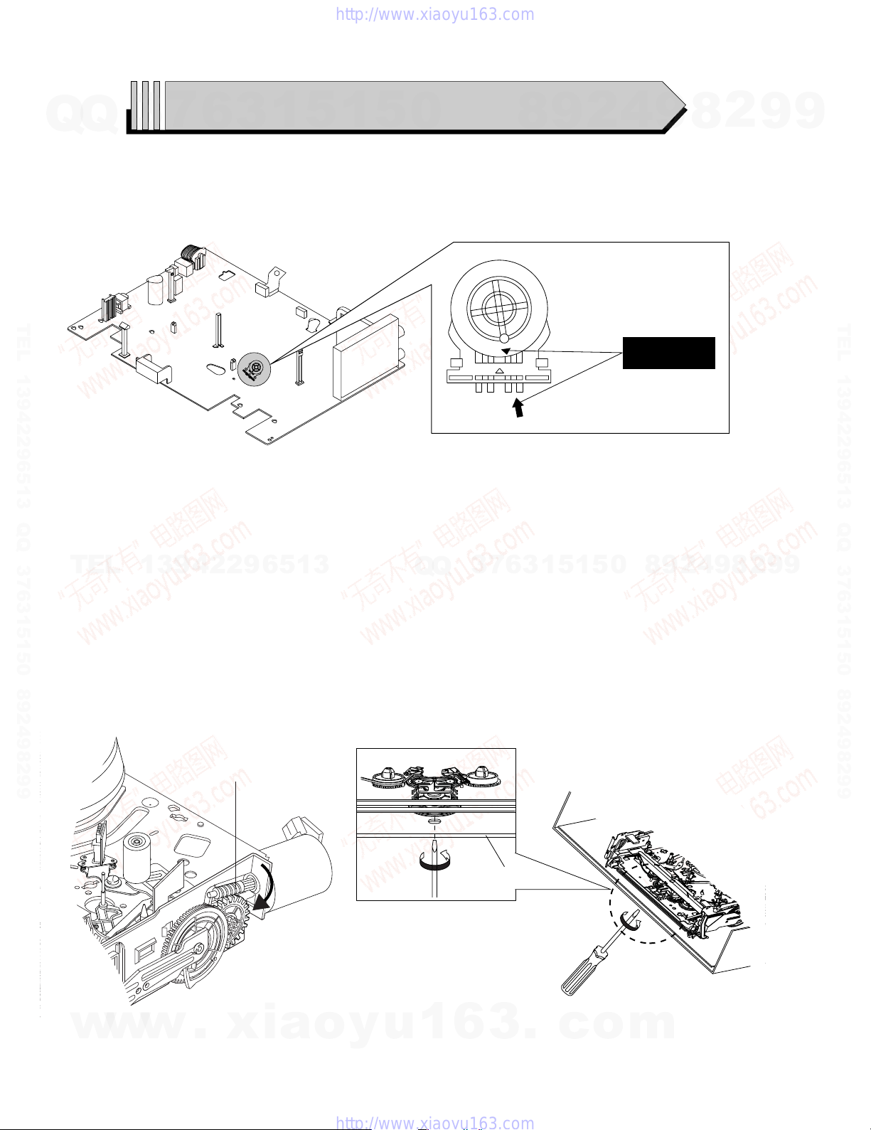
◆ MODE SWITCH (PROGRAM SWITCH) ASSEMBLY POINT
1) When installing the ass’y deck on the Main PCB, be sure to align the assembly point of mode switch.
TEL 13942296513 QQ 376315150 892498299
3
IMPORTANT SERVICE GUIDE
6
3
1
5
1
5
Fig. 1
0
8
9
4
2
ASSEMBLY POINT
(ALIGN TWO ARROWS)
9
8
2
9
9
TEL 13942296513 QQ 376315150 892498299
◆ HOW TO EJECT THE CASSETTE TAPE
(If the tape is stuck in the unit)
TEL
1) Turn the Gear Worm 1 clockwise in the direction of arrow with a screwdriver. (See Fig. 2)
(Other method ; Remove the screw of Motor Load Ass’y, Separate the Motor Load Ass’y)
2) When Slider S, T approachs the unloading position, rotate holder Clutch counterclockwise after inserting screwdriver in the frame’s bottom hole
in order to wind the unwound tape. (Refer to Fig. 3)
(If you rotate Gear Worm 1 continuously when tape is unwinding, you may cause tape contamination by grease and tape damage. Be sure to
wind the unwound tape with the unit in the horizontall position.)
3) Rotate Gear Worm 1 clockwise using a screwdriver until the mecha is in the eject state. Remove the tape. (Refer to Fig. 2)
13942296513
1 GEAR WORM
Q
Q
3
7
6
3
1
5
1
5
0
8
9
2
4
9
8
2
9
9
w
w
w
Fig. 2
.
xia
o
y
u
1
6
— 4 —
3
.
Fig. 3
c
o
m
SLV-ED343ME/ED343SG/ED949ME/ED949SG/
EZ141AZ/EZ745AZ/GA59ME/GA59SG
1. GENERAL
Q
TEL 13942296513 QQ 376315150 892498299
Getting Started
Q
Index to parts and controls
Refer to the pages indicated in parentheses ( ) for details.
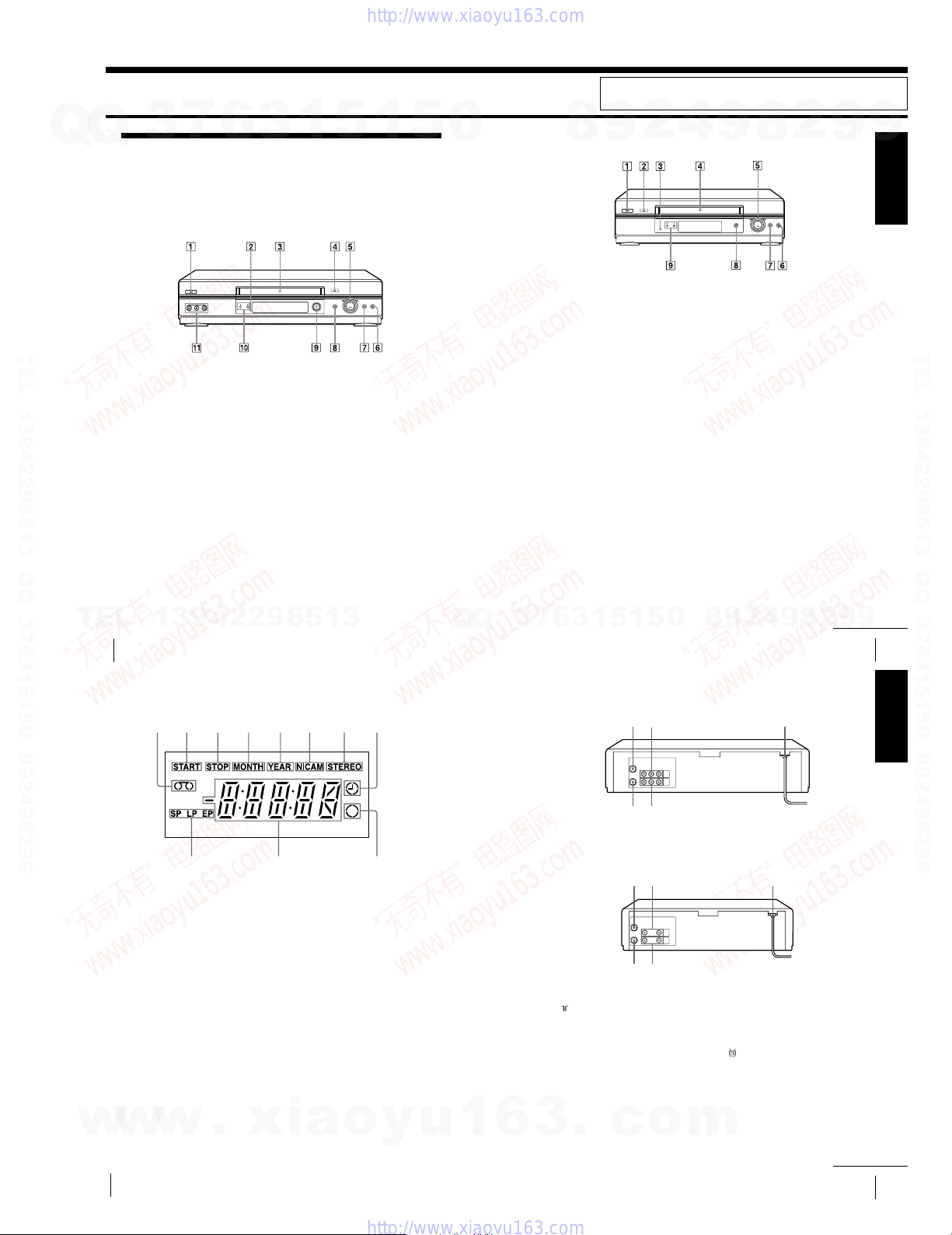
Front panel
For SLV-ED949ME/SG
1 ?/1 ON/STANDBY switch
2 Remote sensor (11)
3 Tape compartment
4 A EJECT button (30)
5 H PLAY button* (30) (45)/M FF
6 x STOP button (17) (30) (60)
7 X PAUSE button (30) (41) (60)
7
3
(fast-forward)/m REW (rewind)
(30) (45)/Playback Dial (31) (45)
6
1
3
5
8 z REC (record) button (33) (47)
(60)
9 EASY TIMER (36)
q; PROGRAM/TRACKING +/—
buttons* (37) (54)
qa LINE-2 IN VIDEO/AUDIO L/R
(left/right) jacks (58)
*The H PLAY and PROGRAM/
TRACKING + buttons have a tactile dot.
1
5
0
This section is extracted from SLV-ED343ME/ED343SG/
ED949ME/ED949SG instruction manual. (3-090-243-11)
4
For SLV-ED343ME/SG
8
1 ?/1 ON/STANDBY switch
2 A EJECT button (30)
3 Remote sensor (11)
4 Tape compartment
5 H PLAY button* (30) (45)/M FF
(fast-forward)/m REW (rewind)
(30) (45)/Playback Dial (31) (45)
9
2
2
8
9
6 x STOP button (17) (30) (60)
7 X PAUSE button (30) (41) (60)
8 z REC (record) button (33) (47)
(60)
9 PROGRAM/TRACKING +/—
buttons* (37) (54)
*The H PLAY and PROGRAM/
TRACKING + button has a tactile dot.
9
9
Getting Started
TEL 13942296513 QQ 376315150 892498299
TEL
13942296513
Getting Started
4
Index to parts and controls (continued)
Display window
1 Tape indicator
2 START indicator (37)
3 STOP indicator (37)
4 MONTH indicator (40)
5 YEAR indicator (40)
6 NICAM indicator* (51)
7 STEREO indicator* (50)
Q
Q
31452678
90qa
8 Timer indicator (39) (43)
9 Recording indicator (33)
0 Time counter/clock/line/programme
position indicator (31) (32) (59)
qa Ta pe speed indicators (32) (38)
*SLV-ED949ME/SG only
5
1
3
6
7
3
Rear panel
For SLV-ED949ME/SG
For SLV-ED343ME/SG
1 (in from antenna) connector (13)
2 LINE IN 1 AUDIO R/L/VIDEO
(audio right/audio left/video) jacks*
(59)
LINE IN 1 AUDIO/VIDEO jacks*
(58)
3 Mains lead (13)
1
5
45
45
0
9
4
2
9
8
321
321
4 LINE OUT AUDIO R/L/VIDEO
(audio right/audio left/video) jacks*
LINE OUT AUDIO/VIDEO jacks*
1
(14)
2
5 (out to tv) connector (13)
*1SLV-ED949ME/SG only
2
SLV-ED343ME/SG only
*
8
9
9
2
continued
Getting Started
5
Getting Started
1
2
w
w
6
w
Getting Started
.
xia
o
y
u
1
6
1-1
3
.
c
o
m
continued
Getting Started
7
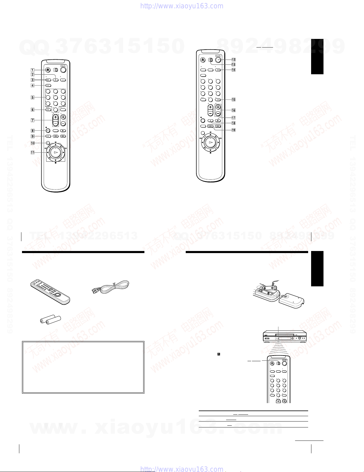
Index to parts and controls (continued)
Remote commander
Q
Q
123
456
789
TEL 13942296513 QQ 376315150 892498299
3
0
7
1 Z EJECT button (30)
6
2 INPUT SELECT button (32) (42)
(60)
3 TV/VIDEO button (for TV)
4 CLEAR button (31) (48)
5 Programme number buttons* (34)
6 -/-- (tens digit) button (34)
7 VOL (volume) +/— buttons
8 z REC (record) button (33) (47)
9 REC SPEED (recording speed)
button (32)
q; MENU button (21) (48)
qa X PAUSE/M button (21) (30)
x STOP/m button (21) (30)
m REW (rewind)/< button (21)
(30) (45)
M FF (fast-forward)/, button
(21) (30) (45)
H PLAY/OK button* (21) (30)
(45)
*The H PLAY, AUDIO MONITOR,
number 5 and PROG + buttons have a
tactile dot.
3
1
5
1
5
0
123
456
789
0
8
9
qs ?/1 (on/standby) switch (43)
qd ¥TV/VIDEO remote control switch
(11)
4
2
qf AUDIO MONITOR button*
qg DISPLAY button (31) (33)
qh PROG (programme) +/— buttons*
(34)
qj y SLOW button (45)
qk ×2 button (45)
ql ./> INDEX SEARCH
buttons (53)
*1The H PLAY, AUDIO MONITOR,
number 5 and PROG + buttons have a
tactile dot.
2
SLV-ED949ME/SG only
*
9
8
1*2
2
(52)
1
Getting Started
9
9
TEL 13942296513 QQ 376315150 892498299
Getting Started
8
TEL
Step 1 : Unpacking
Check that you have received the following items with the VCR:
¥ Remote commander ¥ Aerial cable
¥ R6 (size AA) batteries
How to use this manual
The instructions in this manual are for the 4 models: SLV-ED949ME/SG and
ED343ME/SG. Check your model name by looking at the rear panel of your
VCR. SLV-ED949ME is the model used for illustration purposes. Any
difference in operation is clearly indicated in the text, for example,
SLV-ED949ME only.
This manual mainly explains operations using the remote commander, but the
same operations can also be performed using the buttons on the VCR having the
same or similar names.
13942296513
1
5
1
3
6
7
3
Q
Q
Step 2 : Setting up the remote
commander
Inserting the batteries
Insert two R6 (size AA) batteries
by matching the + and — on the
batteries to the diagram inside the
battery compartment.
Insert the negative (—) end first,
then push in and down until the
positive (+) end clicks into
position.
Using the
remote commander
You can use this remote
commander to operate this VCR
and a Sony TV. Buttons on the
remote commander marked with
a dot (¥) can be used to operate
your Sony TV. If the TV does
not have the
remote sensor, this remote
commander will not operate the
TV.
symbol near the
0
5
¥TV/VIDEO
2
9
8
Remote sensor
123
456
789
0
Getting Started
9
4
9
2
8
Getting Started
9
9
Getting Started
10
w
w
w
.
xia
o
y
u
1
6
1-2
To operate Set ¥TV/VIDEO to
the VCR VIDEO and point at the remote sensor at the VCR
a Sony TV ¥TV and point at the remote sensor at the TV
3
.
c
o
m
continued
Getting Started
11
Step 2 : Setting up the remote commander (continued)
Notes
7
Q
Q
TEL 13942296513 QQ 376315150 892498299
3
¥ With normal use, the batteries should last about three to six months.
¥ If you do not use the remote commander for an extended period of time, remove
the batteries to avoid possible damage from battery leakage.
¥ Do not use a new battery together with an old one.
¥ Do not use different types of batteries together.
¥ Some buttons may not work with certain Sony TVs.
6
3
1
5
1
5
0
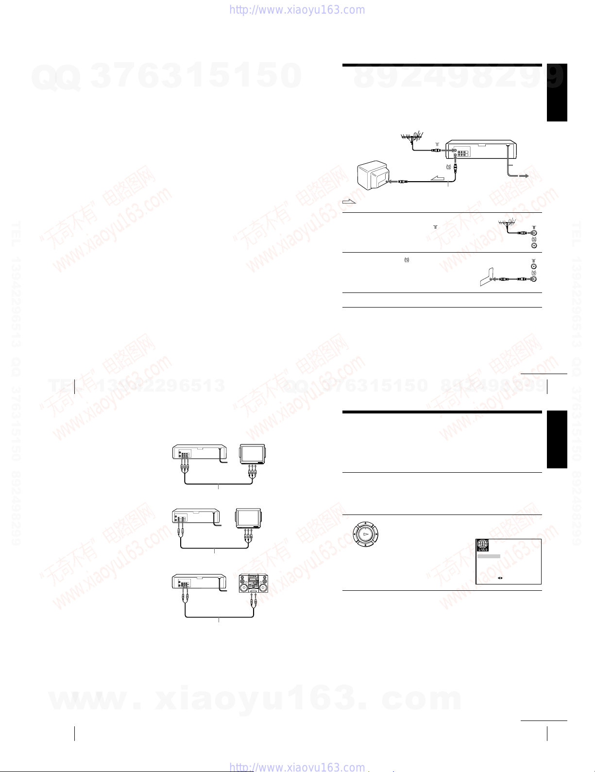
Step 3 : Connecting the VCR
4
2
9
8
Connect the aerial to your VCR and TV as shown below to watch TV
programmes and VCR pictures on your TV. In addition, if your TV has
audio/video (A/V) input jacks, we recommend you connect the VCR to your
TV using an audio/video cable to get a better picture and sound.
Connecting the aerial
AERIAL IN
Aerial cable (supplied)
: Signal flow
1 Disconnect the aerial cable from your
2 Connect of the VCR and the aerial
3 Connect the mains lead to the mains.
TV and connect it to on the rear
panel of the VCR.
input of your TV using the supplied
aerial cable.
Note
¥ When you connect the VCR and your TV only with an aerial cable, you have to
tune your TV to the VCR (see page 15).
9
8
2
9
Mains lead
to mains
Getting Started
9
TEL 13942296513 QQ 376315150 892498299
12
TEL
Getting Started
13942296513
Step 3 : Connecting the VCR (continued)
Additional connections
To a TV that has audio/
video input jacks
This additional connection
improves picture and sound
quality. Connect the TV as
shown on the left.
To a stereo system
(SLV-ED949ME/SG
only)
You can improve sound
quality by connecting a
stereo system to the LINE
OUT AUDIO R/L jacks as
shown on the left.
Note
¥ To play a tape in stereo, you must connect your VCR either to a TV with audio/
video input jacks or to a stereo system as shown on above left.
For SLV-ED949ME/SG
LINE OUT
Audio/video cable (not supplied)
For SLV-ED343ME/SG
LINE OUT
Audio/video cable (not supplied)
LINE OUT
AUDIO R/L
Audio cable (not supplied)
LINE IN
LINE IN
LINE IN
Q
Q
9
4
2
9
8
0
5
1
5
1
3
6
7
3
Step 4 : Setting up the VCR with
the Auto Set Up function
Before using the VCR for the first time, set up the VCR using the Auto Set Up
function. With this function, you can set the language for the on-screen display and
TV channels automatically.
1 Turn on your TV and set it to the video channel.
2 Connect the mains lead to the mains.
Tune the TV to channel 32 (the initial RF channel for this VCR).
Refer to your TV manual for TV tuning instructions. If the picture
does not appear clearly, see To change the RF channel on
page 17.
PLAY
The VCR automatically turns on.
OK
The LANGUAGE SET menu
appears on the TV screen.
Press </, to select the desired
language, ENGLISH or ARABIC,
then press OK.
The message for the Auto Set Up
function appears.
ENGLISH ARABIC
SELECT
8
:
continued
Getting Started
9
9
2
EXIT MENU:OK:SET
13
Getting Started
w
w
14
w
Getting Started
.
xia
o
y
u
1
6
1-3
3
.
c
o
m
continued
Getting Started
15
Step 4 : Setting up the VCR with the Auto Set Up function (continued)
7
Q
Q
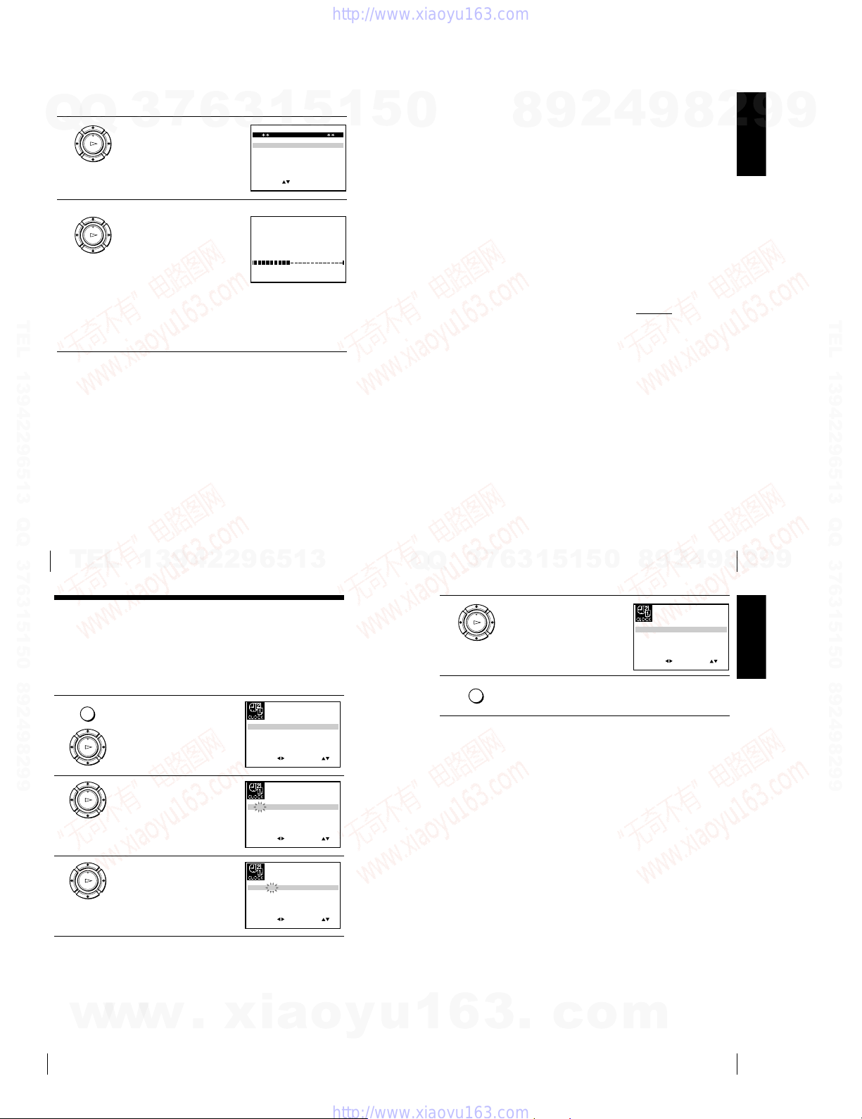
3 Press OK.
4 Press M/m/</, to select the
TEL 13942296513 QQ 376315150 892498299
3
PLAY
The SYSTEM SELECT menu
OK
appears.
appropriate TV system, then press
OK.
PLAY
OK
The VCR starts searching for all of
the receivable channels and presets
them (in the appropriate order for
your local area).
If you want to change the order of
the channels or disable unwanted
programme positions, see
Changing/disabling programme
positions on page 25.
After the search is complete, the clock setting menu appears. See
Setting the clock on page 18.
6
3
SYSTEM
SYSTEM
SYSTEM
SELECT
1
SYSTEM SELECT
–B/G
D/K–
–
I
:
AUTO SET UP
PLEASE WAIT
5
EXIT MENU:OK:SET
EXIT
1
40%
MENU:
5
0
To cancel the Auto Set Up function
Press MENU.
To change the RF channel
If the picture does not appear clearly on the TV, change the RF channel on
the VCR and TV. Select INSTALLATION from the menu, then press M/m
to highlight VCR OUTPUT CH and press ,. Select the RF channel by
pressing the M/m buttons. Then, tune the TV to the new RF channel so that
a clear picture appears.
Tip
¥ If you want to change the language for the on-screen display from the one preset
in the Auto Set Up function, see page 21.
Notes
¥ Whenever you operate the Auto Set Up function, some of the settings (timer, etc.)
will be reset. If this happens, you have to set them again.
¥ Auto preset starts automatically only when you plug in the mains lead for the first
time after you purchase the VCR.
¥ After using the Auto Set Up function, the LANGUAGE SET menu does not
appear automatically when you connect the mains lead again. If you want to use
the Auto Set Up function again, press MENU, then press M/m/</, to highlight
INSTALLATION and press OK. Press M/m to highlight AUTO SET UP, then
repeat all procedures from step 3.
¥ Auto preset can be performed by pressing x STOP
5 seconds or more with no tape inserted.
8
9
2
4
9
on the VCR continuously for
8
Getting Started
2
9
9
TEL 13942296513 QQ 376315150 892498299
Getting Started
16
TEL
Step 5 : Setting the clock
You must set the time and date on the VCR to use the timer features properly.
Before you start
¥ Turn on the VCR and the TV.
¥ Set the TV to the video channel.
¥ Refer to Index to parts and controls for button locations.
MENU
1 Press MENU, then press M/m/</
PLAY
OK
2 Press M/m to set the hour.
PLAY
OK
3 Press , to select the minutes and
PLAY
OK
13942296513
, to highlight CLOCK SET and
press OK.
set the minutes by pressing M/m.
12 0 1 JAN/0:20
SELECT
18 0 1 JAN/0:20
SELECT
18 3 1 JAN/0:20
SELECT
Getting Started
4
2
9
8
0
5
1
5
1
3
6
7
3
Q
Q
4 Set the day, month, and year in
5 Press MENU to exit the menu.
04/
THU
SET
EXIT
SET
EXIT
SET
EXIT
:
MENU:
04/
THU
:
MENU:
04/
THU
:
MENU:
:
OK:END
:
OK:END
:
OK:END
sequence by pressing , to select
PLAY
the item to be set, and press M/m to
OK
select the digits, then press ,.
The day of the week is set
automatically.
MENU
Tip
¥ To change the digits while setting, press < to return to the item to be changed,
and select the digits by pressing M/m.
18 3 82 SEP/0:20
SELECT
SET
:
EXIT
OK:END
TUE
9
04/
:
MENU:
17
2
8
Getting Started
9
9
Getting Started
18
w
w
w
.
xia
o
y
u
1
6
1-4
3
.
c
o
m
Getting Started
19
Step 6 : Selecting the TV system
Q
Q
3
You must select the appropriate TV system for your area.
Before you start
¥ Turn on the VCR and the TV.
¥ Set the TV to the video channel.
¥ Refer to Index to parts and controls for button locations.
MENU
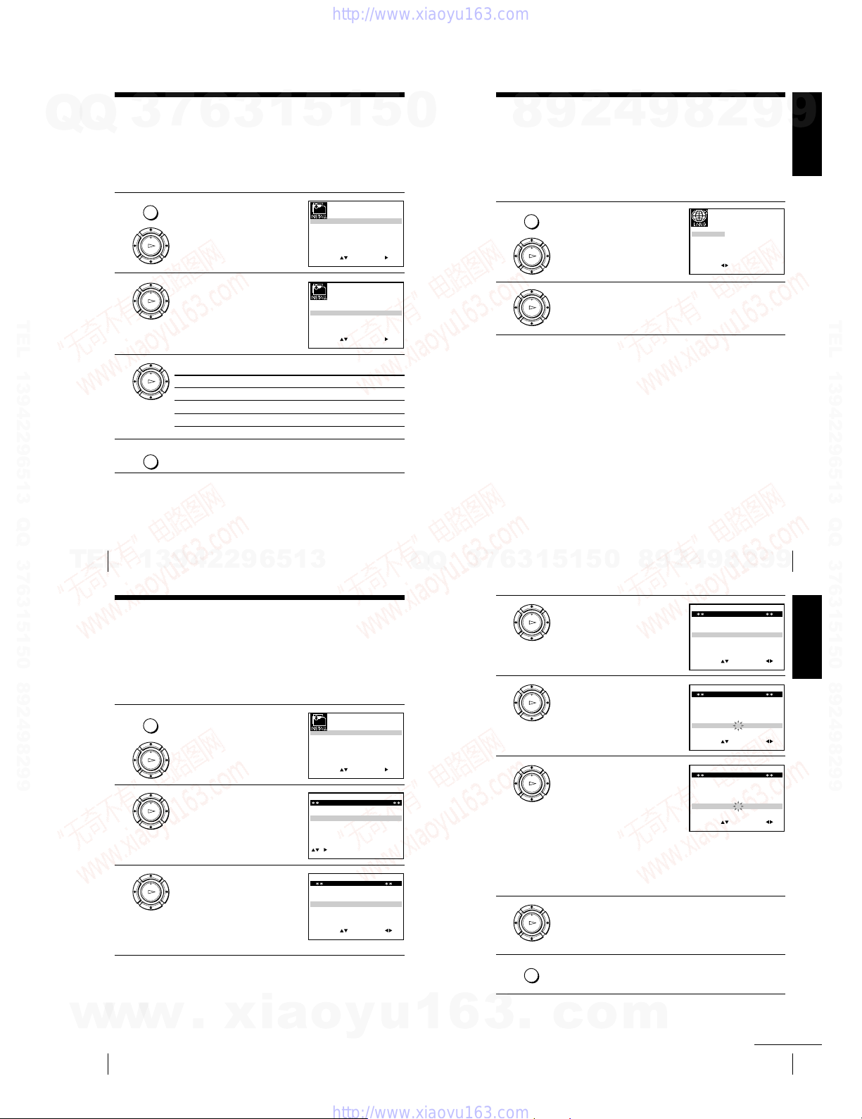
1 Press MENU, then press M/m/</
PLAY
OK
2 Press M/m to highlight TV
PLAY
OK
6
, to highlight INSTALLATION
and press OK.
SYSTEM, then press ,.
7
TEL 13942296513 QQ 376315150 892498299
3 Press , to select the appropriate TV system.
PLAY
Select For
OK
G the B/G TV system
K the D/K TV system
I the I TV system
MENU
4 Press MENU to exit the menu.
3
1
5
AUTO SET UP
MANUAL SET UP
TV SYSTEM
VCR OUTPUT CH
SELECT
AUTO SET UP
MANUAL SET UP
TV SYSTEM
VCR OUTPUT CH
SELECT
1
:
OK:END
:
OK:END
5
G:
32:
SET
:
EXIT
G:
32:
SET
:
EXIT
0
MENU:
MENU:
Selecting a language
4
2
9
8
You can change the on-screen display language from the one you selected with the
Auto Set Up function.
Before you start
¥ Turn on the VCR and the TV.
¥ Set the TV to the video channel.
¥ Refer to Index to parts and controls for button locations.
MENU
1 Press MENU, then press M/m/</
2 Press </, to highlight the desired language, ENGLISH or
, to highlight LANGUAGE SET
and press OK.
PLAY
OK
PLAY
ARABIC, then press OK.
OK
9
2
8
ENGLISH ARABIC
SELECT
:
9
EXIT MENU:OK:SET
Getting Started
9
TEL 13942296513 QQ 376315150 892498299
20
TEL
Getting Started
13942296513
Presetting channels
If some channels could not be preset using the Auto Set Up function, you can preset
them manually.
Before you start
¥ Turn on the VCR and the TV.
¥ Set the TV to the video channel.
¥ Refer to Index to parts and controls for button locations.
MENU
1 Press MENU, then press M/m/</
2 Press M/m to highlight MANUAL
3 Press M/m to highlight the row
, to highlight INSTALLATION
and press OK.
PLAY
OK
SET UP, then press ,.
PLAY
OK
which you want to preset, then
PLAY
OK
press ,.
To display other pages for
programme positions 6 to 80, press
M/m repeatedly.
AUTO SET UP
MANUAL SET UP
TV SYSTEM
VCR OUTPUT CH
SELECT
TV STATION TABLE
PR CH NAME SYSTEM
1
0
2
2
0
2
3
0
3
4
0
3
5
MANUAL TUNING
SYSTEM : B/G
PR : 5
CH : –––
MFT : –
NAME : – – – –
SELECT
:
OK:END
7
9
0
2
:
G:
32:
SET
:
EXIT
A
A
B
–
L
M
N
–
C
D
E
–
I
J
K
–
SWAPPING OK
EXIT MENU:CLEAR:DELETE
SET :
EXIT
Getting Started
2
8
9
4
2
9
8
0
5
1
5
1
3
6
7
3
Q
Q
4 Press </, repeatedly until the
5 Press M/m to highlight NAME,
MENU:
B/G
B/G
B/G
B/G
:
6 Enter the station name.
7 Press OK to confirm the station name.
MENU:OK:END
channel you want is displayed.
PLAY
Select the appropriate TV system, if
OK
necessary.
then press ,.
PLAY
OK
PLAY
1 Press M/m to select a character.
OK
Each time you press M, the
character changes as shown
below.
A t B t t Z t 0 t 1
t t 9 t A
2 Press , to set the next character.
The next space flashes.
To correct a character, press </, until the character you want
to correct flashes, then reset it.
You can set up to 4 characters for the station name.
PLAY
OK
MANUAL TUNING
SYSTEM : B/G
PR : 5
CH : 033
MFT : –
NAME : ––––
SELECT
:
MANUAL TUNING
SYSTEM : B/G
PR : 5
CH : 033
MFT : –
NAME : ––––
SELECT
:
MANUAL TUNING
SYSTEM : B/G
PR : 5
CH : 033
MFT : –
NAME : O– – –
SELECT
:
SET :
EXIT
SET :
EXIT
SET :
EXIT
9
MENU:OK:END
MENU:OK:END
MENU:OK:END
21
9
Getting Started
w
w
22
w
Getting Started
.
xia
o
y
u
1
6
1-5
MENU
8 Press MENU to exit the menu.
3
.
c
o
m
continued
Getting Started
23

Presetting channels (continued)
Changing/disabling programme
Q
If the picture is not clear
Q
If the picture is not clear, you may use the Manual Fine Tuning (MFT)
function. After step 4, press M/m to select MFT. Press </, to get a clear
picture, then press MENU to exit the menu.
Notes
• If the TV sound is distorted or noisy, select the appropriate TV system (“G”, “K”
or “I”) for your area (see page 20).
•When adjusting MFT, the menu may become difficult to read due to interference
from the picture being received.
TEL 13942296513 QQ 376315150 892498299
3
7
6
3
1
5
1
5
0
positions
After setting the channels, you can change the programme positions as you like. If
any programme positions are unused or contain unwanted channels, you can disable
them.
You can also change the station names. If the station names are not displayed, you
can enter them manually.
Changing programme positions
Before you start
¥ Turn on the VCR and the TV.
¥ Set the TV to the video channel.
¥ Refer to Index to parts and controls for button locations.
MENU
1 Press MENU, then press M/m/</
PLAY
OK
2 Press M/m to highlight MANUAL
PLAY
OK
3 Press M/m to highlight the row
PLAY
OK
2
9
8
, to highlight INSTALLATION
and press OK.
SET UP, then press ,.
containing the programme position
you want to change.
To display other pages for
programme positions 6 to 80, press
M/m repeatedly.
4
9
AUTO SET UP
MANUAL SET UP
TV SYSTEM
VCR OUTPUT CH
SELECT
:
OK:END
TV STATION TABLE
PR CH NAME SYSTEM
1
0
2
7
2
0
2
9
3
0
3
0
4
0
3
2
5
TV STATION TABLE
PR NAME SYSTEM
CH
1
0
2
7
2
0
2
9
3
0
3
0
4
0
3
2
5
8
G:
32:
SET
EXIT
A
A
B
–
L
M
N
–
C
D
E
–
I
J
K
–
SWAPPING OK
EXIT MENU:CLEAR:DELETE
A
A
B
–
L
M
N
–
C
D
E
–
I
J
K
–
SWAPPING OK
EXIT
2
:
MENU:
B/G
B/G
B/G
B/G
:
B/G
B/G
B/G
B/G
:
MENU:CLEAR:DELETE
Getting Started
9
9
TEL 13942296513 QQ 376315150 892498299
Getting Started
24
TEL
Changing/disabling programme positions (continued)
4 Press OK, then press M/m to move
PLAY
OK
5 Press OK to confirm the setting.
PLAY
OK
6 To change the programme position of another station, repeat steps 3
MENU
7 Press MENU to exit the menu.
Disabling unwanted programme positions
After presetting channels, you can disable unused programme positions. The
disabled positions will be skipped later when you press the PROG +/— buttons.
Before you start
¥ Turn on the VCR and the TV.
¥ Set the TV to the video channel.
¥ Refer to Index to parts and controls for button locations.
MENU
1 Press MENU, then press M/m/</
PLAY
OK
w
Getting Started
26
13942296513
to the desired programme position.
through 5.
, to highlight INSTALLATION,
and press OK.
w
w
.
xia
TV STATION TABLE
PR NAME SYSTEM
CH
1
0
2
7
2
0
3
0
3
0
3
2
4
0
2
9
5
AUTO SET UP
MANUAL SET UP
TV SYSTEM
VCR OUTPUT CH
SELECT
:
OK:END
A
A
B
–
C
D
E
–
I
J
K
–
L
M
N
–
SWAPPING OK
EXIT
G:
32:
SET
EXIT
o
:
B/G
B/G
B/G
B/G
MENU:
MENU:
:
y
u
8
0
5
1
5
1
3
6
7
3
Q
Q
2 Press M/m to highlight MANUAL
3 Press M/m to highlight the row
4 Press CLEAR.
5 Repeat steps 3 and 4 for any other programme positions you want
6 Press MENU to exit the menu.
1
6
SET UP, then press ,.
PLAY
OK
which you want to disable.
PLAY
OK
To display other pages for
programme positions 6 to 80, press
M/m repeatedly.
CLEAR
The selected row will be cleared as
shown on the left.
to disable.
MENU
Note
¥ Be sure to select the programme position you want to disable correctly. If you
disable a programme position by mistake, you need to reset that channel manually.
3
.
c
o
PR CH NAME SYSTEM
1
2
3
4
5
PR CH NAME SYSTEM
1
2
3
4
5
PR NAME SYSTEM
1
2
3
4
5
m
Getting Started
2
9
TV STATION TABLE
0
2
7
A
A
B
0
2
9
L
M
N
0
3
0
C
D
E
0
3
2
I
J
K
SWAPPING OK
TV STATION TABLE
0
2
7
A
A
B
0
2
9
L
M
N
0
3
0
C
D
E
0
3
2
I
J
K
SWAPPING OK
TV STATION TABLE
CH
0
2
7
A
A
B
0
3
0
C
D
E
0
3
2
I
J
K
SWAPPING OK
Getting Started
continued
4
–
–
–
–
EXIT MENU:CLEAR:DELETE
–
–
–
–
EXIT MENU:CLEAR:DELETE
–
–
–
EXIT
continued
9
B/G
B/G
B/G
B/G
B/G
B/G
B/G
B/G
B/G
B/G
B/G
MENU:CLEAR:DELETE
:
:
:
25
2
8
Getting Started
27
9
9
1-6
Changing/disabling programme positions (continued)
Q
Changing the station names
Q
You can change or enter the station names (up to 4 characters).
Before you start
¥ Turn on the VCR and the TV.
¥ Set the TV to the video channel.
¥ Refer to Index to parts and controls for button locations.
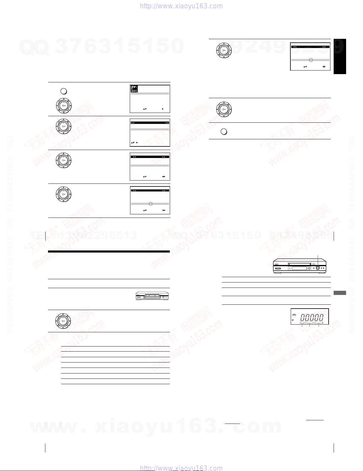
1 Press MENU, then press M/m/</
2 Press M/m to highlight MANUAL
TEL 13942296513 QQ 376315150 892498299
3 Press M/m to highlight the row
4 Press M/m to highlight NAME,
3
MENU
PLAY
OK
PLAY
OK
PLAY
OK
PLAY
OK
7
6
3
, to highlight INSTALLATION
and press OK.
SET UP, then press ,.
which you want to change or enter
the station name, then press ,.
To display other pages for
programme positions 6 to 80, press
M/m repeatedly.
then press ,.
1
5
1
5
AUTO SET UP
MANUAL SET UP
TV SYSTEM
VCR OUTPUT CH
:
OK:END
TV STATION TABLE
0
2
7
A
A
B
0
2
9
L
M
N
0
3
0
C
D
E
0
3
2
I
J
K
SWAPPING OK
MANUAL TUNING
:
MANUAL TUNING
:
SET
EXIT
–
–
–
–
EXIT MENU:CLEAR:DELETE
SET :
EXIT
SET :
EXIT
SELECT
PR CH NAME SYSTEM
1
2
3
4
5
SYSTEM : B/G
PR : 5
CH : 033
MFT : –
NAME : ––––
SELECT
SYSTEM : B/G
PR : 5
CH : 033
MFT : –
NAME : ––––
SELECT
0
G:
32:
:
MENU:
B/G
B/G
B/G
B/G
:
MENU:OK:END
MENU:OK:END
5 Enter the station name.
PLAY
8
6 Press OK to confirm the new name.
7 Press MENU to exit the menu.
Each time you press M, the
character changes as shown
below.
A t B t t Z t 0 t 1
t t 9 t A
2 Press , to set the next character.
The next space flashes.
To correct a character, press </, until the character you want
to correct flashes, then reset it.
You can set up to 4 characters for the station name.
PLAY
OK
MENU
1 Press M/m to select a character.
OK
9
2
4
9
MANUAL TUNING
SYSTEM : B/G
8
PR : 5
CH : 033
MFT : –
NAME : O– – –
SELECT
2
:
9
SET :
EXIT
Getting Started
9
MENU:OK:END
TEL 13942296513 QQ 376315150 892498299
28
TEL
w
w
Getting Started
13942296513
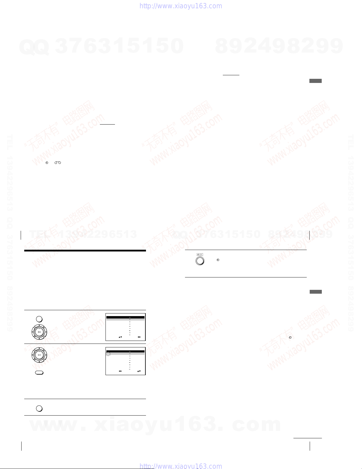
Basic Operations
Playing a tape
Before you start...
¥ Refer to Index to parts and controls for button locations.
1 Tu rn on your TV and set it to the video channel.
2 Insert a tape.
3 Press H PLAY.
The VCR turns on and starts playing
automatically if you insert a tape with
its safety tab removed.
PLAY
When the tape reaches the end, it will rewind automatically.
OK
Additional tasks
To Press
Stop play x STOP
Pause play X PAUSE
Resume play after pause X PAUSE or H PLAY
Fast-forward the tape M FF during stop
Rewind the tape m REW during stop
Eject the tape Z EJECT
To set the colour system
If the playback picture has no colour, or streaks appear during playback, set
COLOUR SYSTEM in the USER SET menu to conform to the system that
the tape was recorded in (see page 56). (Normally set the option to AUTO.)
w
.
xia
o
y
u
Q
Q
1
3
6
6
7
3
Getting Started
2
8
9
4
2
9
8
0
5
1
5
1
3
Using Playback Dial on the VCR
With Playback Dial, you can
operate the following playback
options.
To Do this
Resume play after pause Press H PLAY
Fast-forward the tape
Rewind the tape
To use the time counter
Press CLEAR at the point on the tape that you
want to find later. The counter in the display
window resets to 0:00:00. Search for the
point afterwards by referring to the counter.
To display the counter on the TV screen, press DISPLAY.
Notes
¥ When you play back a tape recorded in the PAL or MESECAM colour system,
streaks may appear even if the colour system setting is set to AUTO. If so, set
COLOUR SYSTEM to PAL or MESECAM in the USER SET menu (see
page 56).
¥ Do not turn Playback Dial forcibly. It may damage Playback Dial.
¥ The counter resets to 0:00:00 whenever a tape is reinserted.
¥ The counter stops counting when it comes to a portion with no recording.
¥ If a tape has portions recorded in both PAL and NTSC systems, the time counter
reading will not be correct. This discrepancy is due to the difference between the
counting cycles of the two colour systems.
¥ Depending on your TV, the following may occur while playing an NTSC-recorded
tape:
— The picture becomes black and white.
— The picture shakes.
— No picture appears on the TV screen.
— Black streaks appear horizontally on the TV screen.
— The colour density increases or decreases.
¥ Ta pes recorded in the LP mode of other NTSC system VCRs can be played back
on this VCR, but the picture quality cannot be guaranteed.
¥ While setting the menu on the TV screen, buttons for playback
commander do not function.
.
c
Quickly turn and release Playback Dial to the right
(M FF) during stop
Quickly turn and release Playback Dial to the left
(m REW) during stop
o
m
Playback Dial
Hour Minute Second
on the remote
9
29
9
Basic Operations
Basic Operations
30
1-7
Basic Operations
31
Recording TV programmes
Q
Q
Before you start...
¥ Refer to Index to parts and controls for button locations.
3
7
6
3
1
5 Press z REC to start recording.
5
1
5
0
REC
The recording indicator lights up red in the display
8
window.
9
2
4
9
8
2
9
9
1 Turn on your TV and set it to the video channel.
2 Insert a tape with its safety tab in place.
3 ¥To record a normal channel, press PROG +/— until the
TEL 13942296513 QQ 376315150 892498299
4 Press REC SPEED to select the tape speed (SP or LP for the PAL
Basic Operations
32
TEL
If no picture or sound is reproduced on the TV, press TV/VIDEO
on the remote commander to display VIDEO indicator on the
display window.
• PROG
programme position number or station name you want appears in
the display window.
INPUT
SELECT
¥To record from other equipment connected to one or more of the
LINE inputs, press INPUT SELECT to display the connected line
in the display window.
REC SPEED
colour system, and SP or EP for the NTSC colour system).
LP (Long Play) provides recording time twice as long as SP
(Standard Play). EP (Extended Play) provides recording time three
times as long as SP. However, SP produces better picture and audio
quality.
13942296513
Q
Q
To stop recording
Press x STOP.
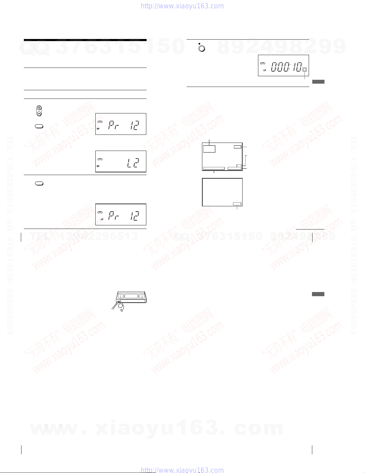
To check the remaining time
Press DISPLAY. Each time you press DISPLAY, the display changes as
shown below.
Sound system, TV system, colour system, programme position, tape speed
and time counter t Remaining time t Current date and time, and time
counter
Sound system, TV system and colour system
STEREO
PAL
AUTO
21 /
Current date and time
In order to get an accurate remaining time indication, be sure TAPE
SELECT in the USER SET menu is set according to the tape type you use
(see page 56).
7
3
UN 12 : 0 0
J
6
Remaining time
1
3
PR 1
REMAIN
5
SP
62:38:5
09:0
1
Programme position
Tape speed
Time counter
8
0
5
Recording indicator
Basic Operations
4
2
9
continued
9
Basic Operations
33
2
8
9
TEL 13942296513 QQ 376315150 892498299
9
Recording TV programmes (continued)
To watch another TV programme while recording
1 If the TV is connected to the VCR using an audio/video cable, set the
TV to TV input. If the TV is connected to the VCR using only the
aerial cable, skip this step.
2 Select another programme position on the TV.
To save a recording
To prevent accidental erasure, break off the
safety tab as illustrated. To record on the same
tape again, cover the tab hole with adhesive
tape.
To record NTSC colour system programmes
NTSC colour signals can be recorded on this VCR from the LINE IN 1 and
LINE-2 IN* jacks.
To select the line input, press INPUT SELECT to display the connected line
in the display window.
For tape speed, select SP or EP in step 4.
EP (Extended Play) provides recording time three times as long as SP.
However, SP produces better picture and sound quality.
When playing a tape, the VCR automatically detects the tape speed.
Tips
¥ To select a programme position, you can use the programme number buttons on
the remote commander. For two-digit numbers, press -/-- (tens digit) followed by
the programme number buttons.
¥ If you connect additional equipment to the LINE IN 1 or LINE-2 IN* jacks, you
can select the input signal using the INPUT SELECT or PROG +/— buttons.
¥ The DISPLAY information appears on the TV screen indicating information about
the tape, but the information will not be recorded on the tape.
¥ If you do not want to watch TV while recording, you can turn off the TV.
Safety tab
Notes
¥ The DISPLAY information does not appear during still (pause) mode or slow-
motion playback.
¥ If a tape has portions recorded in both PAL and NTSC systems, the time counter
reading will not be correct. This discrepancy is due to the difference between the
counting cycles of the two video systems.
¥ When you insert a non-standard commercially available tape, the remaining time
may not be correct.
¥ The remaining time is intended for rough measurement only.
¥ About 30 seconds after the tape begins playback, the tape remaining time will be
displayed.
*SLV-ED949ME/SG only
Basic Operations
Basic Operations
34
w
w
w
.
xia
o
y
u
1
6
1-8
3
.
c
o
m
Basic Operations
35
Recording TV programmes using the
Q
TEL 13942296513 QQ 376315150 892498299
Easy Timer (SLV-ED949ME/SG only)
Q
The Easy Timer function allows you to
make timer recordings of programmes
without turning on your TV. Set the
recording timer to record up to eight
programmes, including settings made with
other timer methods, that will be broadcast
within the next month. The recording start
time and recording stop time can be set at
one minute intervals.
Before you start...
¥ Insert a tape with its safety tab in place. Make sure the tape is longer than the total
¥ Refer to Index to parts and controls for button locations.
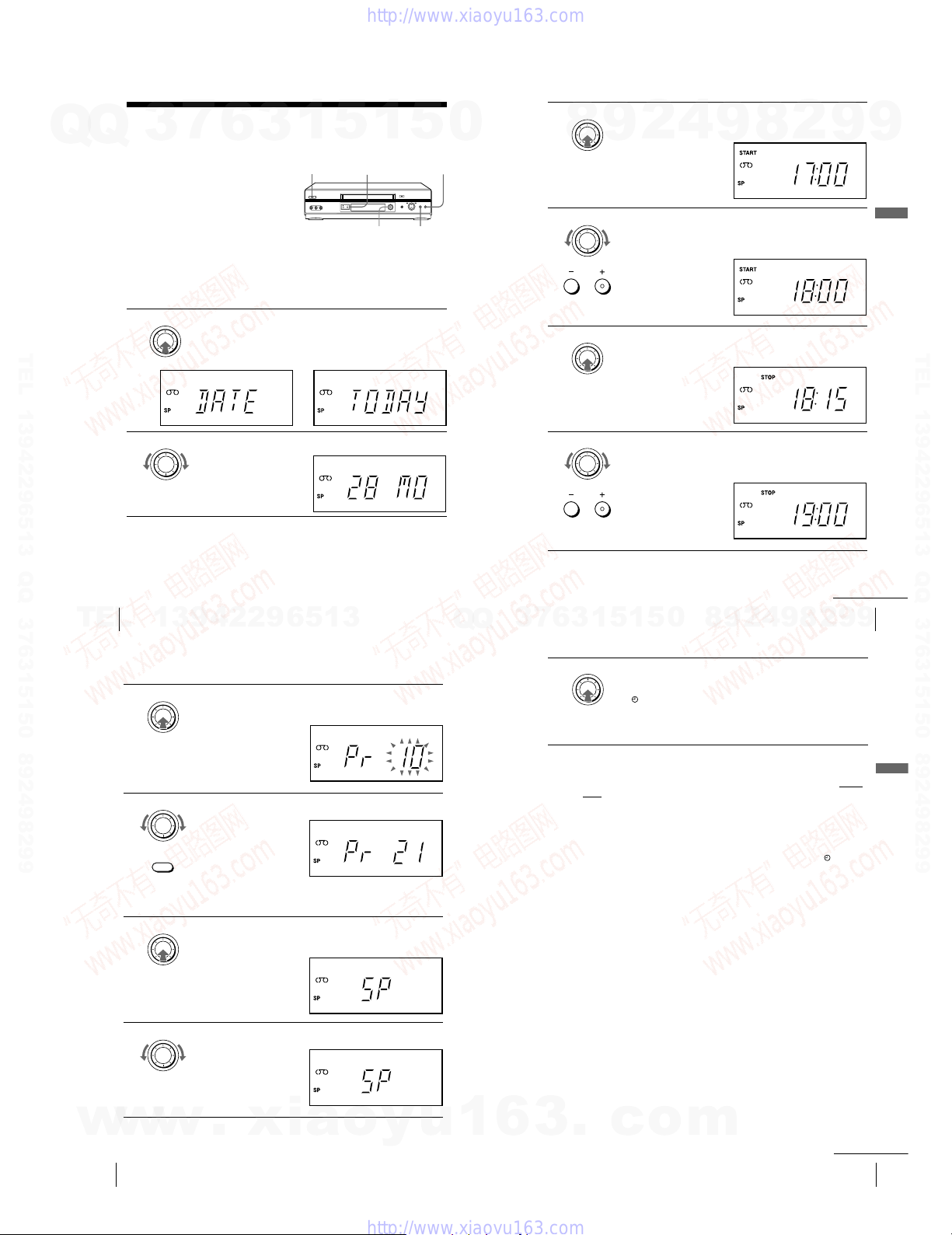
1 Press EASY TIMER.
3
recording time.
EASY TIMER
7
6
DATE and TODAY appear alternately in the display window.
If the date and time are not set, DAY will appear. See step 2 in
the following section, To set the clock to set the date and time.
3
?/1 ON/STANDBY
1
n
5
PROGRAM +/—
EASY TIMER
1
5
x STOP
X PAUSE
0
EASY TIMER
3 Press EASY TIMER.
8
4 Turn EASY TIMER to set the recording start time.
5 Press EASY TIMER.
START indicator and the current time appear in the display
9
window.
EASY TIMER
You can set the recording start time in 15 minute intervals or adjust
the time in one minute intervals by pressing the PROGRAM +/—
buttons.
PROGRAM
EASY TIMER
STOP indicator and the recording stop time appear in the display
window.
2
4
9
8
2
9
9
Basic Operations
TEL 13942296513 QQ 376315150 892498299
36
TEL
EASY TIMER
2 Turn EASY TIMER to set the recording date.
Basic Operations
13942296513
Recording TV programmes using the Easy Timer (continued)
EASY TIMER
7 Press EASY TIMER.
8 Turn EASY TIMER to set the programme position.
9 Press EASY TIMER.
10 Turn EASY TIMER to set the tape speed, SP, LP or AUTO.
The programme position or LINE input appears in the display
window.
EASY TIMER
INPUT
SELECT
To record from other equipment connected to one or more of the
LINE inputs, turn EASY TIMER or press INPUT SELECT to
display the connected line in the display window.
EASY TIMER
The current tape speed mode appears in the display window.
EASY TIMER
Q
Q
EASY TIMER
6 Turn EASY TIMER to set the recording stop time.
6
7
3
11 Press EASY TIMER to complete the setting.
You can set the recording stop time in 15 minute intervals or adjust
the time in one minute intervals by pressing the PROGRAM +/—
buttons.
PROGRAM
9
8
0
5
1
5
1
3
EASY TIMER
“OK” appears in the display window for about five seconds.
The
indicator appears in the display window and the VCR stands
by for recording.
To record from other equipment, leave the connected equipment
switched on.
To return to the previous step
To return to the previous step, press the PROGRAM + and – buttons on the
VCR at the same time during any of the Easy Timer settings.
To stop recording
To stop the VCR while recording, press x STOP.
To use the VCR after setting the timer
To use the VCR before a recording begins, just press ?/1 . The
turns off and the VCR switches on. Remember to press ?/1 to reset the
VCR to recording standby after using the VCR.
You can also do the following tasks while the VCR is recording:
• Reset the counter (page 31).
• Display tape information on the TV screen (page 33).
• Check the timer settings (page 48).
•Watch another TV programme (page 34).
To use the Auto Tape Speed function
In step 10 above, turn EASY TIMER to select AUTO. When you are
recording a programme in the SP mode and the remaining tape length
becomes shorter than the recording time, the recording tape speed is
automatically changed to the LP mode (or EP mode when you are recording
NTSC signals). Note that some noise will appear on the picture when the
tape speed is changed. To operate this function correctly, the “TAPE
SELECT” setting in the USER SET menu must be accurate (see page 56).
2
4
9
Basic Operations
2
8
continued
9
indicator
37
9
Basic Operations
w
w
38
w
Basic Operations
.
xia
o
y
u
1
6
1-9
3
.
c
o
m
continued
Basic Operations
39
Recording TV programmes using the Easy Timer (continued)
Q
To set the clock
Q
1 Hold down EASY TIMER so that DAY appears in the display
window. However, if the clock has already been set, the current setting
appears.
3
7
6
3
1
5
1
5
2 Turn EASY TIMER to set the day.
3 Press EASY TIMER.
MONTH indicator and 1 appear in the display window.
4 Turn and press EASY TIMER to set the month, and then the year.
After you set the year, CLOCK appears in the display window.
5 Turn and press EASY TIMER to set the hour and minute.
6 When you have finished setting the time, press EASY TIMER to start
the clock.
Tips
¥ To cancel a Easy Timer setting, press x STOP
the setting.
TEL 13942296513 QQ 376315150 892498299
¥ To check, change, or cancel the programme setting, see Checking/changing/
cancelling timer settings on page 48.
¥ To record NTSC signals in EP mode, set the tape speed to LP. Even when timer
recording is set to LP mode, NTSC signals are automatically recorded in EP
mode.
Notes
¥ If eight programmes have already been set using the TIMER PROGRAMMING
menu, FULL appears in the display window for about five seconds.
and indicators flash in the display window when you complete the
¥ The
setting in step 11 with no tape inserted.
¥ When the time is set incorrectly, ERROR appears in the display window in step
11. Set the timer again from step 1.
on the VCR while you are making
About the Demonstration Mode
The Easy Timer function has a Demonstration Mode that allows the user, such as a
salesperson, to enter more than eight examples of timer settings when demonstrating
0
the use of the Easy Timer. It cancels the FULL notice which appears if eight
programmes have already been set. Do not use the Demonstration Mode for making
timer recordings. Doing so may cause the settings to be inaccurate.
To activate the Demonstration Mode
Press X PAUSE on the VCR while turning the EASY TIMER. DEMO
appears in the display window for a few seconds.
To cancel the Demonstration Mode
Turn the power off and unplug the mains lead. Although the Demonstration
Mode is cancelled, the timer settings entered while using the Demonstration
Mode will remain. Be sure to manually cancel the timer settings before you
use the Easy Timer or any other timer method after reconnecting the mains
lead (see page 48).
8
9
2
4
9
8
2
Basic Operations
9
9
TEL 13942296513 QQ 376315150 892498299
Basic Operations
40
TEL
Recording TV programmes using the
timer
You can preset a total of eight programmes, including settings made with the Easy
Timer (SLV-ED949ME/SG only).
Before you start…
• Check that the VCR clock is set to the correct time and date.
• Insert a tape with its safety tab in place. Make sure the tape is longer than the total
recording time.
•Turn on your TV and set it to the video channel.
• Refer to “Index to parts and controls” for button locations.
MENU
1 Press MENU, then press M/m/</
PLAY
OK
2 Set the date, start and stop times
PLAY
OK
INPUT
SELECT
MENU
3 Press MENU to exit the menu.
13942296513
, to highlight TIMER
PROGRAMMING and press OK.
and tape speed:
1 Press , to select each item in
turn.
2 Press M/m to set each item.
To correct a setting, press < to
return to that setting and reset.
•To record the same programme every day or the same day every
week, see “Daily/weekly recording” on page 43.
•To record from other equipment connected to one or more of the
LINE inputs, press INPUT SELECT to display the connected line
in the “PR”
position.
PR DAY START STOP
–– –––– –– –– – –––::
–– –––– –– –– – –––::
–– –––– –– –– – –––::
–– –––– –– –– – –––::
–– –––– –– –– – ––
–– –––– –– –– – –––::–
–– –––– –– –– – –––::–
–– –––– –– –– – –––::–
PR DAY START STOP
35 –––– –– –– – –––::
–– –––– –– –– – –––::
–– –––– –– –– – –––::
–– –––– –– –– – –––::
–– –––– –– –– – ––
–– –––– –– –– – –––::
–– –––– –– –– – –––::–
–– –––– –– –– – –––::–
SELECT
:
OK:END
SET :SELECT :
EXIT
SET
EXIT
Q
Q
3
7
6
3
1
5
1
5
0
8
9
Basic Operations
4
2
9
8
41
2
9
9
4 Press ?/1 to turn off the VCR.
The
indicator appears in the display window and the VCR stands
by for recording.
To record from other equipment, leave the connected equipment
switched on.
To stop recording
To stop the VCR while recording, press x STOP.
Daily/weekly recording
In step 2 above, press m to select the recording pattern. Each time you press
m , the indication changes as shown below. Press M to change the indication
in reverse order.
–
–
–
–
––::
MENU:OK:END
–
–
–
–
––::
–
:
MENU:
today t DLY (Monday to Sunday) t W-SA (every Saturday) .....
t W-SU (every Sunday) t 1 month later t (dates count down)
t today
To use the VCR after setting the timer
To use the VCR before a recording begins, just press ?/1. The
turns off and the VCR switches on. Remember to press ?/1 to reset the
VCR to recording standby after using the VCR.
You can also do the following tasks while the VCR is recording:
• Reset the counter (page 31).
• Display tape information on the TV screen (page 33).
• Check the timer settings (page 48).
•Watch another TV programme (page 34).
To use the Auto Tape Speed function
In step 2 above, press m to select AUTO. When you are recording a
programme in the SP mode and the remaining tape length becomes shorter
than the recording time, the recording tape speed is automatically changed
to the LP mode (or EP mode when you are recording NTSC signals). Note
that some noise will appear on the picture when the tape speed is changed.
To operate this function correctly, the “TAPE SELECT” setting in the
USER SET menu must be accurate (see page 56).
indicator
Basic Operations
Basic Operations
42
w
w
w
.
xia
o
y
u
1
6
1-10
3
.
c
o
m
continued
Basic Operations
43
Recording TV programmes using the timer (continued)
Tips
7
Q
Q
TEL 13942296513 QQ 376315150 892498299
3
¥ To set the line input video source, you can also use the INPUT SELECT button.
¥ To check, change, or cancel the programme setting, see Checking/changing/
cancelling timer settings on page 48.
¥ To record NTSC signals in EP mode, set the tape speed to LP. Even when timer
recording is set to LP mode, NTSC signals are automatically recorded in EP
mode.
Note
¥ The
no tape inserted.
6
and indicators flash in the display window when you press ?/1 with
3
1
5
1
5
0
Additional Operations
Playing/searching at various speeds
9
8
Before you start
¥ Refer to Index to parts and controls for button locations.
Playback Options
To Do this
View the picture during
fast-forward or rewind
Play at high speed
Play at twice the normal
speed
Play in slow motion
To resume normal playback
Press H PLAY.
Using Playback Dial on the VCR
With Playback Dial, you can
operate the following playback
options.
To Do this
View the picture during
fast-forward or rewind
Play at high speed ¥ During playback, quickly turn and release Playback
4
2
9
During fast-forward, hold down M FF. During
rewind, hold down m REW.
¥ During playback, briefly press M FF or m REW.
The tape continues to play at high speed.
¥ During playback, hold down M FF or m REW.
When you release the button, normal playback
resumes.
During playback, press ×2.
During playback, press y SLOW.
During fast-forward, turn and hold Playback Dial to the
right (M FF). During rewind, turn and hold Playback
Dial to the left (m REW).
Dial to the right (M FF) or left (m REW). The
tape continues to play at high speed.
¥ During playback, turn and hold Playback Dial to the
right (M FF) or left (m REW). When you
release Playback Dial, normal playback resumes.
8
2
9
Playback Dial
9
Additional Operations
TEL 13942296513 QQ 376315150 892498299
44
TEL
w
w
Basic Operations
13942296513
Playing/searching at various speeds (continued)
Tip
¥ Adjust the picture using the PROGRAM +/— buttons on the VCR if:
- Streaks appear while playing in slow motion.
- Bands appear at the top or bottom while pausing.
-The picture shakes while pausing.
To set tracking to the centre position, press both buttons (+/—) at the same time.
Notes
¥ The sound is muted during these operations.
¥ In the LP mode, noise may appear or there may be no colour.
¥ If the playback mode mark does not appear on the TV screen, press DISPLAY.
¥ The picture may show noise when playing at high speed in reverse.
¥ Do not turn Playback Dial forcibly. It may damage Playback Dial.
w
.
xia
o
y
u
Q
Q
1
3
6
Additional Operations
8
9
4
2
9
8
0
5
1
5
1
3
6
7
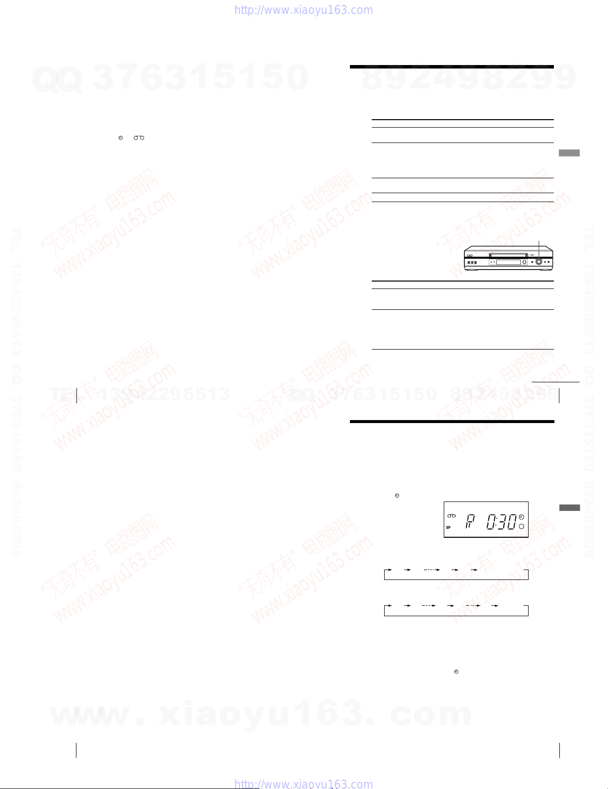
Setting the recording duration time
After you have started recording in the normal way, you can have the VCR stop
recording automatically after a specified duration.
Before you start…
• Refer to “Index to parts and controls” for button locations.
1 While recording, press z REC.
The
indicator appears in the display window.
2 Press z REC repeatedly to set the duration time.
In SP mode
3
Each press advances the time in increments of 30 minutes.
0:30 1:00
In LP (EP) mode
Each press advances the time as shown below.
0:30 1:00
The tape counter decreases minute by minute to 0:00, then the VCR
stops recording and turns off automatically.
To extend the duration
Press z REC repeatedly to set a new duration time.
To cancel the duration
Press z REC repeatedly until the
returns to the normal recording mode.
To stop recording
To stop the VCR while recording, press x STOP.
Note
•You cannot display the current tape time in the display window when setting the
.
c
recording duration time.
o
4:00 4:30
4:00
Normal recording
9:005:00
indicator disappears and the VCR
m
Normal
recording
2
continued
9
9
45
Additional Operations
Additional Operations
46
1-11
Additional Operations
47

When the timer settings overlap
Checking/changing/cancelling timer
settings
Q
Q
Before you start
¥ Turn on your TV and set it to the video channel.
¥ Refer to Index to parts and controls for button locations.
3
7
6
3
1
5
1
5
0
The programme that starts first has priority and the second programme starts
recording only after the first programme has finished. If the programmes
start at the same time, the programme listed first in the menu has priority.
1 Press ?/1 to turn on the VCR.
2 Press MENU, then press M/m/</, to highlight TIMER
PROGRAMMING and press OK.
¥ If you want to change or cancel a
setting, go on to the next step.
¥ If you do not need to change or
cancel the settings, press MENU,
then turn off the VCR to return to
recording standby.
TEL 13942296513 QQ 376315150 892498299
3 Press M/m to select the setting you
want to change or cancel, then press
,.
The PR number on the selected row
flashes.
4 ¥ To change the setting, press </, to select the item you want to
change, then press M/m to reset it.
¥ To cancel the setting , press CLEAR.
PR DAY START STOP
35 SA29 19 0 02 000::
29 SA29 21002 301::
30 SA 6 12001 303::
–– –––– –– –– – –––::
–– –––– –– –– – ––
–– –––– –– –– – –––::
–– –––– –– –– – –––::–
–– –––– –– –– – –––::–
SELECT
:
OK:END
PR DAY START STOP
35 SA29 19 0 02 000::
29 SA29 21002 301::
30 SA 6 12001 303::
–– –––– –– –– – –––::
–– –––– –– –– – ––
–– –––– –– –– – –––::
–– –––– –– –– – –––::–
–– –––– –– –– – –––::–
SELECT
:
OK:END
SET
EXIT
SET
EXIT
SP
–
–
–
––::
–
:
MENU:
SP
–
–
–
––::
–
:
MENU:
5 Press MENU to exit the menu.
If any settings remain, turn off the VCR to return to recording standby.
8
Programme 1
Programme 2
Programme 1
Programme 2
4
2
9
about 20 seconds
will be cut off
about 20 seconds will be cut off
9
8
2
9
Additional Operations
9
TEL 13942296513 QQ 376315150 892498299
Additional Operations
48
TEL
Recording stereo and bilingual
programmes (SLV-ED949ME/SG only)
In the ZWEITON (German stereo) system
This VCR automatically receives and records stereo and bilingual
programmes based on the ZWEITON system. When a stereo or bilingual
programme is received, the STEREO indicator appears in the display
window.
To select bilingual sound while recording
Press AUDIO MONITOR to select the sound you want.
To listen to On-screen display Display window
Main
Sub
Main and sub MAIN/SUB STEREO
Standard sound* MONO STEREO
* Usually the main channel heard from both the left and right in bilingual
programmes
To select stereo programme while recording
To listen to On-screen display Display window
Stereo STEREO STEREO
Left channel LCH STEREO
Right channel RCH STEREO
Standard sound* LCH + RCH STEREO
* Usually the mixed sound of left and right channels in stereo programmes
13942296513
MAIN
SUB
STEREO
STEREO
Q
Q
Additional Operations
4
2
9
8
0
5
1
5
1
3
6
7
3
In the NICAM system
This VCR receives and records stereo and bilingual programmes based on
the NICAM system (NICAM appears on the TV screen). When a stereo or
bilingual programme is received, the STEREO indicator appears in the
display window.
To record a NICAM programme, NICAM in the USER SET menu should
be set to ON (initial setting). To check the menu setting, see page 56 for
details.
To select the sound while recording
Press AUDIO MONITOR to select the sound you want.
Stereo programmes
To listen to On-screen display Display window
Stereo
Left channel NICAM, LCH NICAM, STEREO
Right channel
Left and right channels* NICAM, LCH + RCH NICAM, STEREO
* Usually the mixed sound of left and right channels
Bilingual programmes
To listen to On-screen display Display window
Main
Sub
Main and sub
Standard sound* NICAM, MONO NICAM, STEREO
* Usually the main sound (monaural)
NICAM, STEREO NICAM, STEREO
NICAM, RCH NICAM, STEREO
NICAM, MAIN NICAM, STEREO
NICAM, SUB NICAM, STEREO
NICAM, MAIN/SUB NICAM, STEREO
49
2
8
9
Additional Operations
9
9
w
Additional Operations
50
w
w
.
xia
o
y
u
1
6
1-12
3
.
c
o
m
continued
continued
Additional Operations
51
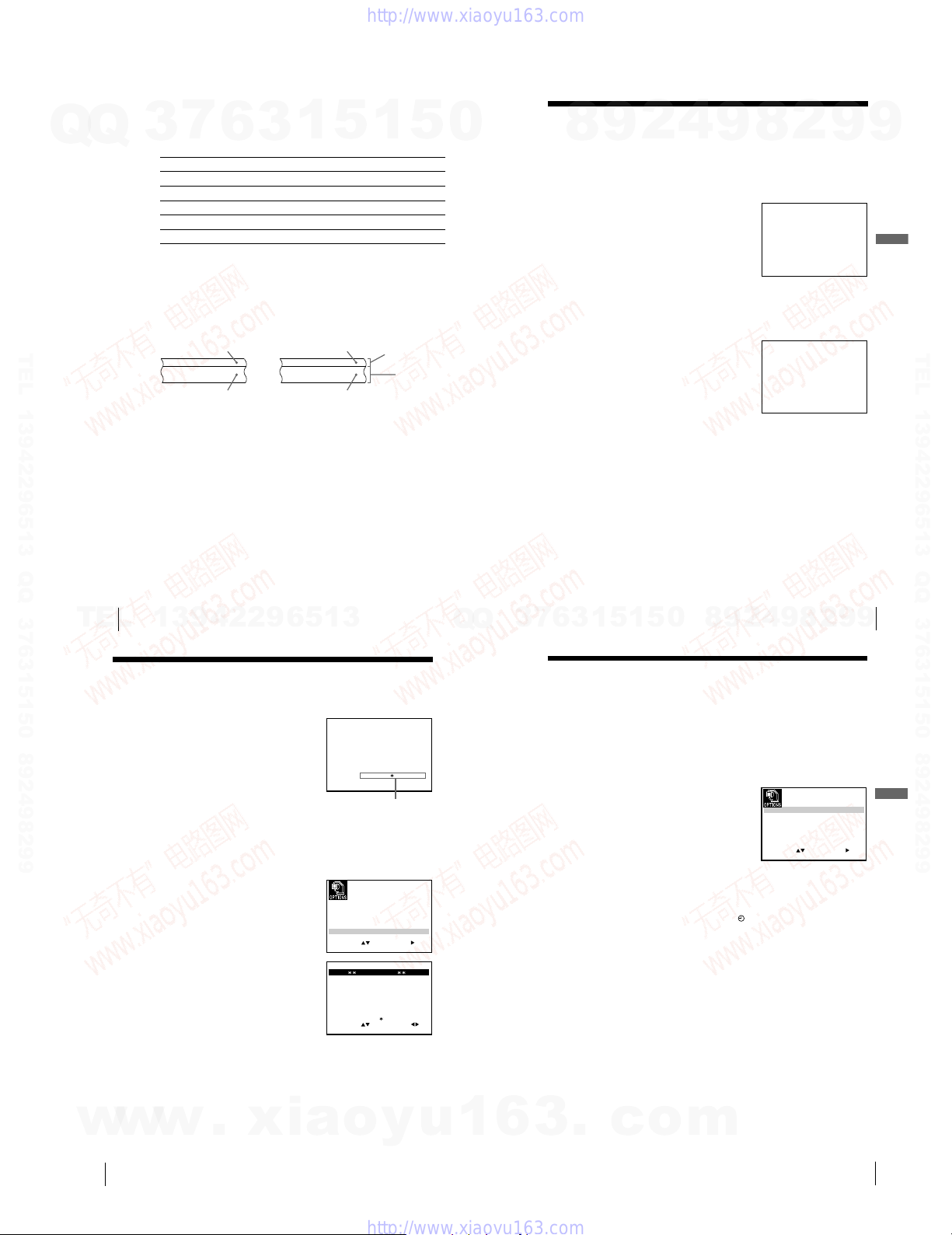
Recording stereo and bilingual programmes (SLV-ED949ME/SG only)
(continued)
Selecting the sound during Hi-fi playback
7
Q
Q
3
Press AUDIO MONITOR to select the sound you want.
To listen to On-screen display Display window
Stereo
Left channel
Right channel
Mix sound*
Mono sound
*The mixed sound of left and right channels, and the normal mono audio track
How sound is recorded on a video tape
The VCR records sound onto two separate tracks. Hi-fi audio is recorded
onto the main track along with the picture. Monaural sound is recorded
onto the normal audio track along the edge of the tape.
Bilingual
TEL 13942296513 QQ 376315150 892498299
Notes
¥ To listen to playback sounds in stereo, you must use the AUDIO OUT
connections.
¥ When you play a tape recorded in monaural, the sound is heard in monaural
regardless of the AUDIO MONITOR setting.
6
Usually main sound
Main (left channel)
Sub (right channel)
1
5
3
STEREO STEREO
LCH STEREO
RCH STEREO
MIX STEREO
MONO No indicator
Stereo
Usually mixed
left/right channels
Stereo sound
(left/right channels)
1
Normal
audio track
(monaural)
5
Hi-fi audio
track (main
track)
0
Searching using the index function
4
2
9
8
The VCR automatically marks the tape with an index signal at the point where each
recording begins. Use these signals as references to find a specific recording.
To find a specific recording by scanning (Index scan)
9
8
2
9
1 Insert an indexed tape into the VCR.
2 Press ./> INDEX SEARCH.
The VCR starts scanning each
recording for five seconds in the
corresponding direction.
3 Press H PLAY to start playback when
you find the desired point.
To search a specific recording (Index search)
:
INDEX SCAN BB
1 Insert an indexed tape into the VCR.
2 Press ./> INDEX SEARCH twice.
•To search ahead, press > INDEX
SEARCH twice.
•To search backwards, press .
INDEX SEARCH twice.
3 Press ./> INDEX SEARCH
depending on the direction where your
desired programme is located.
Each time you press the button, the number increases or decreases up
to ±20, respectively.
4 The VCR starts searching, and playback starts automatically from that
point.
To stop searching
Press x STOP.
Notes
• No index signal will be added when recording starts from recording pause.
However, an index signal will be marked if you change the programme position
during recording pause.
• When you press .
selected index signal, playback may not start exactly at the index signal.
INDEX SEARCH, if there is nothing recorded before the
INDEX SEARCH : BB +02
9
Additional Operations
TEL 13942296513 QQ 376315150 892498299
TEL
13942296513
Adjusting the picture
Adjusting the tracking
Although the VCR automatically adjusts the
tracking when playing a tape, distortion may
occur if the recording is in poor condition.
In this case, manually adjust the tracking.
During playback, press TRACKING +/— on
the VCR to display the tracking meter. The
distortion should disappear as you press one
of the two buttons. To resume automatic
tracking adjustments, eject the tape and re-insert it.
Adjusting the picture sharpness (Auto Sharpness Control)
You can automatically adjust the sharpness of the picture.
1 During playback, press MENU, then press M/m/</, to highlight
USER SET and press OK.
2 Press M/m to highlight ASC, then press
,.
Additional Operations
52
3 Press M/m to set ASC to ON or OFF.
¥ ON: Picture sharpness is automatically
adjusted.
¥ OFF: Adjust the picture sharpness
manually.
To soften the picture, press <.
To sharpen the picture, press ,.
4 Press MENU to return to the original screen.
TRACKING– – – – – – – – – – – –
Tracking meter
OSD :
TAPE SELECTON:
COLOUR SYSTEM
NICAM
POWER SAVE
SELECT
SOFTEN
ON/OFF :
END EXIT
:
SET
EXIT
OK:END
PICTURE
ASC : OFF
–– –––––––––– ––– ––––––
SET
OK:
E180
: AUTO
ON:
OFF:
ON:ASC
:
MENU:
SHARPEN
:
MENU:
Q
Q
9
4
2
9
8
0
5
1
5
1
3
6
7
3
Reducing the VCRs power
consumption
You can turn off the indicators in the display window when the VCR is off (standby
mode) to reduce the VCRs power consumption.
1 Press MENU, then press M/m/</, to highlight USER SET and
press OK.
2 Press M/m to highlight POWER SAVE.
3 Press , to set to ON, then press OK.
The power consumption is reduced to a
minimum.
To turn on the indicators in the display window
Set POWER SAVE to OFF in step 3.
Note
¥ When the VCR stands by for recording, the indicator in the display window
remain lit even when POWER SAVE is set to ON.
OSD ON:
TAPE SELECT E1 8 0:
COLOUR SYSTEM AUTO:
NICAM
SELECT
Additional Operations
9
2
8
ON:
OFF:POWER SAVE
ON:ASC
SET
:
:
EXIT
OK:END
53
9
Additional Operations
MENU:
w
w
Additional Operations
54
w
.
xia
o
y
u
1
6
1-13
3
.
c
o
m
Additional Operations
55
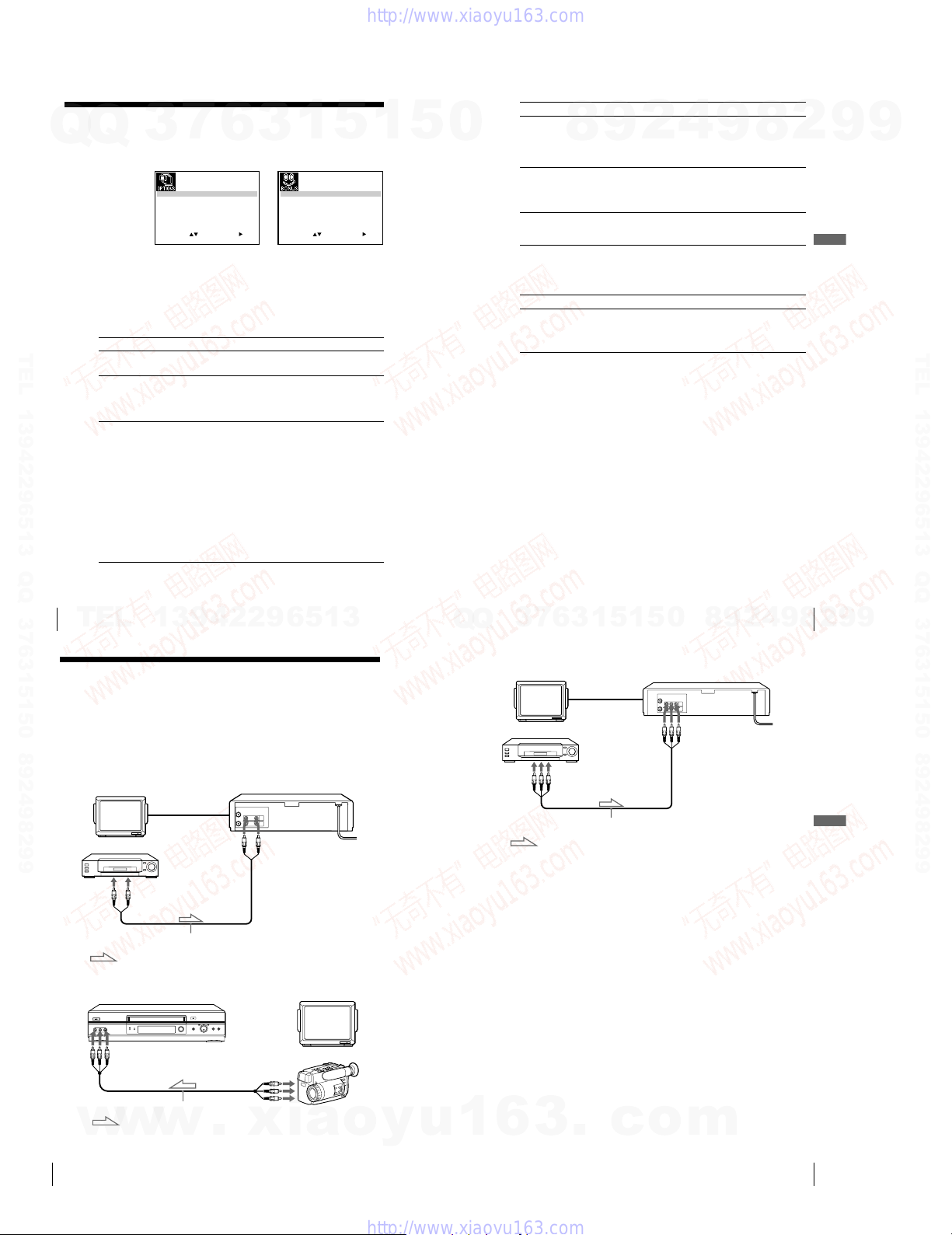
Changing menu options
Q
Q
1 Press MENU, then select USER SET or EASY OPERATION and press
OK.
2 Press M/m to select the option.
3 Press < to change the setting, then press OK.
Menu choices
Initial settings are indicated in bold print.
USER SET
TEL 13942296513 QQ 376315150 892498299
Menu option Set this option to
OSD ¥ ON to display the menu on the TV screen.
TAPE SELECT ¥ E180 to use an E-180 or shorter type tape.
COLOUR SYSTEM ¥ AUTO to select the colour system automatically.
7
3
OSD ON:
TAPE SELECT E1 8 0:
COLOUR SYSTEM AUTO:
NICAM
SELECT
:
1
:
OK:END
5
SET
EXIT
6
3
AUTO POWER OFF OFF:
ON:
OFF:POWER SAVE
ON:ASC
SET
EXIT
OK:END
¥ OFF to disappear the menu from the TV screen.
¥ E240 to use an E-240 type tape.
¥ E260 to use an E-260 type tape.
¥ E300 to use an E-300 type tape.
¥ PAL to use the tape recorded in the PAL colour
system.
¥ MESECAM to use the tape recorded in the
MESECAM colour system.
¥ B/W to use the tape recorded in black and white.
When using the tape recorded NTSC colour signals:
¥ NT3.58 to use the tape recorded in the NTSC 3.58
colour system.
¥ NT4.43 to use the tape recorded in the NTSC 4.43
colour system.
¥ NTPB to play back an NTSC-recorded tape on PAL
TV.
SELECT
:
MENU:
:
MENU:
1
5
0
Menu option Set this option to
NICAM*
POWER SAVE
ASC ¥ ON to automatically adjust the sharpness of the
EASY OPERATION
Menu option Set this option to
AUTO POWER OFF
*SLV-ED949ME/SG only
8
¥ ON to record NICAM broadcasts on the hi-fi audio
track.
9
¥ OFF to record standard sound on the hi-fi audio
track.
For details, see page 51.
¥ ON to turn off the indicators in the display window
to conserve the VCRs power.
¥ OFF to turn on the indicators in the display window
while the VCR is standing by.
picture.
¥ OFF to manually adjust the sharpness of the picture.
¥ OFF to deactivate the Auto Power Off function.
¥ 2HOUR/3HOUR to turn the VCR off automatically
if no signal is received and you do not press any of
the buttons during this time.
2
4
9
8
2
9
Additional Operations
9
TEL 13942296513 QQ 376315150 892498299
Additional Operations
56
TEL
Editing
Connecting to a VCR or stereo
system
How to connect to record on this VCR
Connect the line outputs of the other VCR to the input connector of this
VCR. Refer to the examples A through C and choose the connection that
best suits your VCR.
Example A (SLV-ED343ME/SG only)
Other VCR (Player)
LINE OUT
Example B (SLV-ED949ME/SG only)
13942296513
TV Your VCR (Recorder)
Audio/video cable (not supplied)
: Signal flow
Your VCR (Recorder) TV
LINE-2 IN
LINE IN 1
LINE OUT
3
Q
Q
Example C (SLV-ED949ME/SG only)
Other VCR (Player)
LINE OUT
How to connect to a stereo system (SLV-ED949ME/SG
only)
Connect the LINE-2 IN jacks on this VCR to the audio output jacks on the
stereo system, using an audio cable (not supplied).
Notes
¥ Make sure you connect the plugs to jacks of the same colour.
¥ If the other VCR is a monaural type, leave the red plugs unconnected.
¥ If you connect this VCR to both the LINE IN and LINE OUT jacks of the other
VCR, select the input correctly to prevent a humming noise.
¥ When you connect another VCR to the LINE-2 IN* connector, press INPUT
SELECT to display L2 in the display window.
*SLV-ED949ME/SG only
5
1
3
6
7
TV
Audio/video cable (not supplied)
: Signal flow
1
5
9
8
0
Your VCR (Recorder)
LINE IN 1
Additional Operations
9
4
2
8
57
2
Editing
9
9
58
w
Editing
Audio/video cable (not supplied)
: Signal flow
w
w
.
xia
Other VCR (Player)
o
y
u
1
6
3
.
1-14
c
o
m
Editing
59

Additional Information
Basic editing
Q
Q
When recording on this VCR
Before you start editing
•Turn on your TV and set it to the video
• Press INPUT SELECT to display the
• Press REC SPEED to select the tape
TEL 13942296513 QQ 376315150 892498299
7
3
channel.
connected line in the display window.
speed.
1 Insert a source tape with its safety tab removed into the other
2 Insert a tape with its safety tab in place into this (recording) VCR.
6
(playback) VCR. Search for the point to start playback and set it to
playback pause.
Search for the point to start recording and press X PAUSE to set it to
playback pause.
3
1
5
1
3 Press z REC on this VCR to set it to recording pause.
4 To start editing, press the X PAUSE buttons on both VCRs at the same
time.
To stop editing
Press the x STOP buttons on both VCRs.
Tip
•To cut out unwanted scenes while editing, press X PAUSE on this VCR when an
unwanted scene begins. When it ends, press X PAUSE again to resume recording.
z REC
5
X PAUSE
0
Troubleshooting
4
2
9
8
If you have any questions or problems not covered below, please consult your nearest
Sony service facility.
Symptom Remedy
The ?/1 ON/STANDBY
switch does not function.
The power is turned on but the
VCR does not operate.
Power
The VCR is plugged in but the
display window remains dark.
The clock has stopped and
— —:— — appears in the
Clock
display window.
The playback picture does not
appear on the TV screen.
The picture is not clear. ¥ Existing broadcasts may interfere with the VCR.
Playback
The picture has no colour. ¥ The COLOUR SYSTEM option in the USER SET
The picture rolls vertically
during picture search.
9
¥ Connect the mains lead to the mains securely.
¥ Moisture condensation has occurred. Turn the power
off, unplug the mains lead and leave the VCR to dry
for over three hours.
¥ Set POWER SAVE in the USER SET menu to OFF
(see page 55).
¥ The clock stops if the VCR is disconnected from the
mains. Reset the clock (and timer).
¥ Make sure the TV is set to the video channel. If you
are using a monitor, set it to video input.
¥ If you made connections using the aerial cable only,
make sure the RF channel number is set correctly for
your area.
Reset the RF channel output of your VCR (see page
17).
¥ Adjust the tracking with the TRACKING +/— buttons
on the VCR.
¥ The video heads are dirty (see the last page of
Troubleshooting). Clean the video heads using a
Sony video head cleaning cassette. If a Sony cleaning
cassette is not available in your area, have the heads
cleaned at your nearest Sony service facility (a
standard service charge will be required). Do not use
a commercially available liquid type cleaning cassette
other than Sonys, as it may damage the video heads.
¥ The video heads may have to be replaced. Consult
your local Sony service facility for more information.
menu is set to the wrong position. Set the option to
conform to the system that the tape was recorded in.
¥ Adjust the vertical hold control on the TV or monitor.
8
2
9
9
Additional Information
TEL 13942296513 QQ 376315150 892498299
TEL
13942296513
Troubleshooting (continued)
Symptom Remedy
The picture has no sound.
The sound from a tape
Playback
recorded with the VCR is not
in stereo or the STEREO
indicator in the display
window is flashing.
No TV programme appears on
the TV screen.
TV reception is poor. ¥ Make sure the aerial cable is connected securely.
Recording
The recorded picture has no
colour or unusual colour.
The tape starts playing as
soon as it is inserted.
The tape is ejected when you
press z REC.
Nothing happens when you
press z REC.
Editing
60
¥ The tape is defective.
¥ If you made A/V connections, check the audio cable
connection.
¥ If you made connections using the aerial cable only,
make sure the TV system is set correctly for your
area.
¥ Adjust the tracking.
¥ The video heads are dirty. Clean the video heads
using a Sony video head cleaning cassette as
explained above.
¥ Make sure the TV is set to the video channel. If you
are using a monitor, set it to video input.
¥ Existing broadcasts may interfere with the VCR.
Reset the RF channel output of your VCR (see page
17).
¥ Select the correct source with the INPUT SELECT
button. Select a programme position when recording
TV programmes; select a line input when recording
from other equipment.
¥ Adjust the TV aerial.
¥ Make sure the TV system is correctly set for your TV.
¥ Make sure TV SYSTEM (B/G, D/K or I) in the
INSTALLATION menu is set to the same system in
your local area.
¥ Set COLOUR SYSTEM in the USER SET menu
according to your local colour system.
¥ The safety tab has been removed. To record on this
tape, cover the tab hole (see page 34).
¥ The safety tab has been removed. To record on this
tape, cover the tab hole (see page 34).
¥ Make sure the tape is not at its end.
Q
Q
3
2
9
8
0
5
1
5
1
3
6
7
Symptom Remedy
The timer does not operate. ¥ Check that the clock is set.
Timer recording
A tape cannot be inserted. ¥ Check that a tape is not already in the tape
The remote commander does
not function.
The selected input line
connector number does not
appear in the display window.
Others
The tracking meter does not
appear on the TV screen.
The display window becomes
dim.
The VCR needs to be cleaned.
¥ Make sure a tape has been inserted.
¥ Check that the safety tab has not been removed.
¥ Make sure the tape is not at its end.
¥ Make sure a programme has been set for timer
recording.
¥ Make sure your timer settings are past the current
time.
¥ The clock stops if the VCR is disconnected from the
mains. Reset the clock and timer.
¥ Turn the power off and unplug the mains lead.
compartment.
¥ Make sure you are pointing the remote commander at
the remote sensor on the VCR.
¥ Replace all the batteries in the remote commander
with new ones if they are weak.
¥ Make sure the ¥
set correctly.
¥ Press INPUT SELECT to display the connected line.
¥ The recording condition of the tape is very poor and
tracking cannot be adjusted.
¥ The display window automatically becomes dim
when the VCR is in standby mode.
¥ Clean the cabinet, panel and controls with a dry, soft
cloth, or a soft cloth slightly moistened with a mild
detergent solution. Do not use any type of solvent,
such as alcohol or benzine.
TV/VIDEO remote control switch is
4
9
continued
Additional Information
8
2
9
9
61
Additional Information
w
w
Additional Information
62
w
.
xia
o
y
u
1
6
1-15
3
.
c
o
m
continued
Additional Information
63
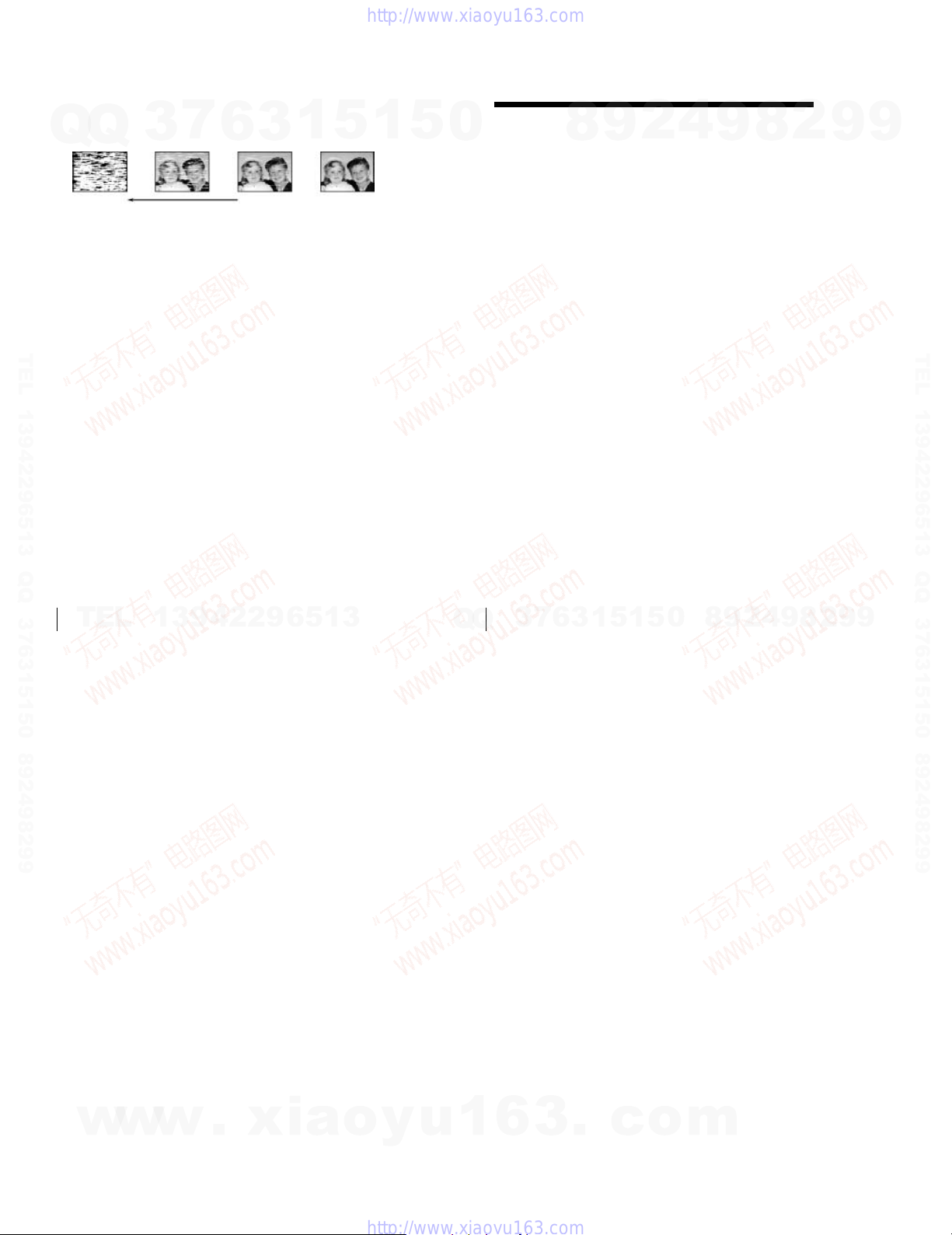
Symptoms caused by contaminated video heads
black & white
screen appears)
Q
Q
terminal
TEL 13942296513 QQ 376315150 892498299
3
7
6
initial
contamination
3
¥ Normal picture¥ Rough picture¥ Unclear picture¥ No picture (or
1
5
1
5
0
Index
A
Adjusting
picture 54
tracking 54
Aerial hookup 13
ASC (Auto Sharpness Control)
54
Audio track 52
Audio/video hookup 14
Auto Set Up 15
C
Changing the programme
position 25
Changing the station name 28
Cleaning the video heads 61
Clock setting 18
Colour system
compatible colour systems
2
setting 30
Connecting
the VCR and your TV 13
to a stereo system 14, 58
to a TV with audio/video
jacks 14
Counter 31
D
Demonstration 41
Disabling the programme
positions 26
Dubbing. see Editing
E
Easy Timer 36
Editing 58
EP mode 32
8
2
9
H
Hi-fi audio track 52
I
Index scan 53
Index search 53
L
Language selection 15, 21
LP mode 32
M
Manual fine tuning 24
Monaural 52
Monitoring
during playback 52
N
Normal audio track 52
O
Optional setting 56
P
Playback 30
at various speeds 45
selecting the sound 52
slow motion 45
Power save 55
Presetting channels 22
4
8
9
R
Recording 32
duration time 47
saving 34
timer setting 42
using the Easy Timer 36
while watching another
programme 34
RF channel 15, 17
S
Safety tab 34
Searching
at various speeds 45
using the index function 53
SP mode 32
Stereo 52
T
Timer setting 42
cancelling 48
changing 48
checking 48
daily/weekly recording 43
using the Easy Timer 36
2
9
9
TEL 13942296513 QQ 376315150 892498299
Additional Information
64
TEL
13942296513
Q
66
Q
Index
3
7
6
3
1
5
1
5
0
8
9
2
4
9
8
2
9
9
w
w
w
.
xia
o
y
u
1
6
1-16E
3
.
c
o
m
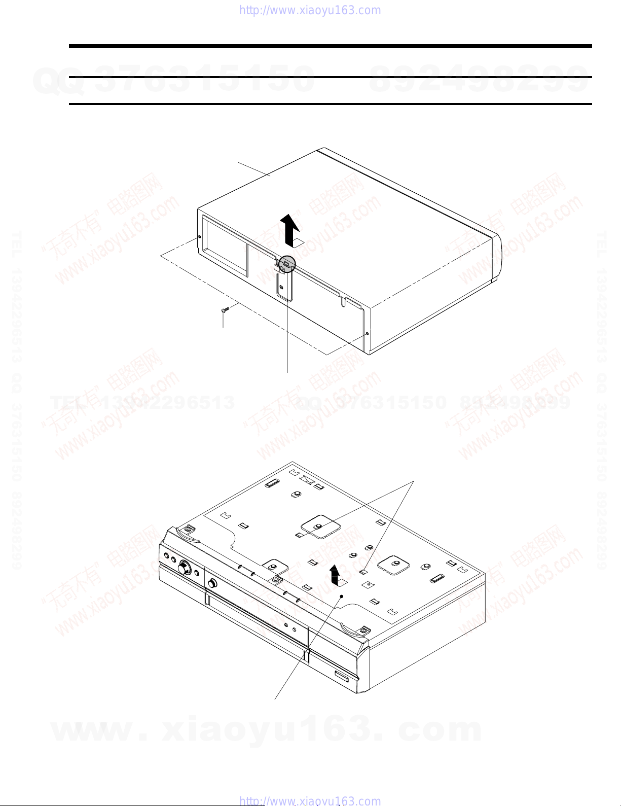
2. DISASSEMBLY AND REASSEMBLY
SLV-ED343ME/ED343SG/ED949ME/ED949SG/
EZ141AZ/EZ745AZ/GA59ME/GA59SG
7
Q
Q
TEL 13942296513 QQ 376315150 892498299
3
2-1 CABINET AND PCB
2-1-1 Cabinet Top
6
2 Lift up the Cabinet Top in the direction of arrow by releasing the Hook.
1
3
CABINET TOP
1 REMOVE 2 SCREWS
5
1
5
0
8
9
2
4
9
8
2
9
9
TEL 13942296513 QQ 376315150 892498299
TEL
13942296513
2-1-2 Cover Bottom
Fig. 2-1 Cabinet Top
Q
Q
3
7
6
3
5
1
5
1
1 RELEASE 2 SNAPFITS
0
8
9
2
4
9
8
2
9
9
w
w
w
.
xia
2 Lift up the Bottom Cover in the direction of arrow.
o
y
u
1
6
Fig. 2-2 Cover Bottom
2-1
3
.
c
o
m
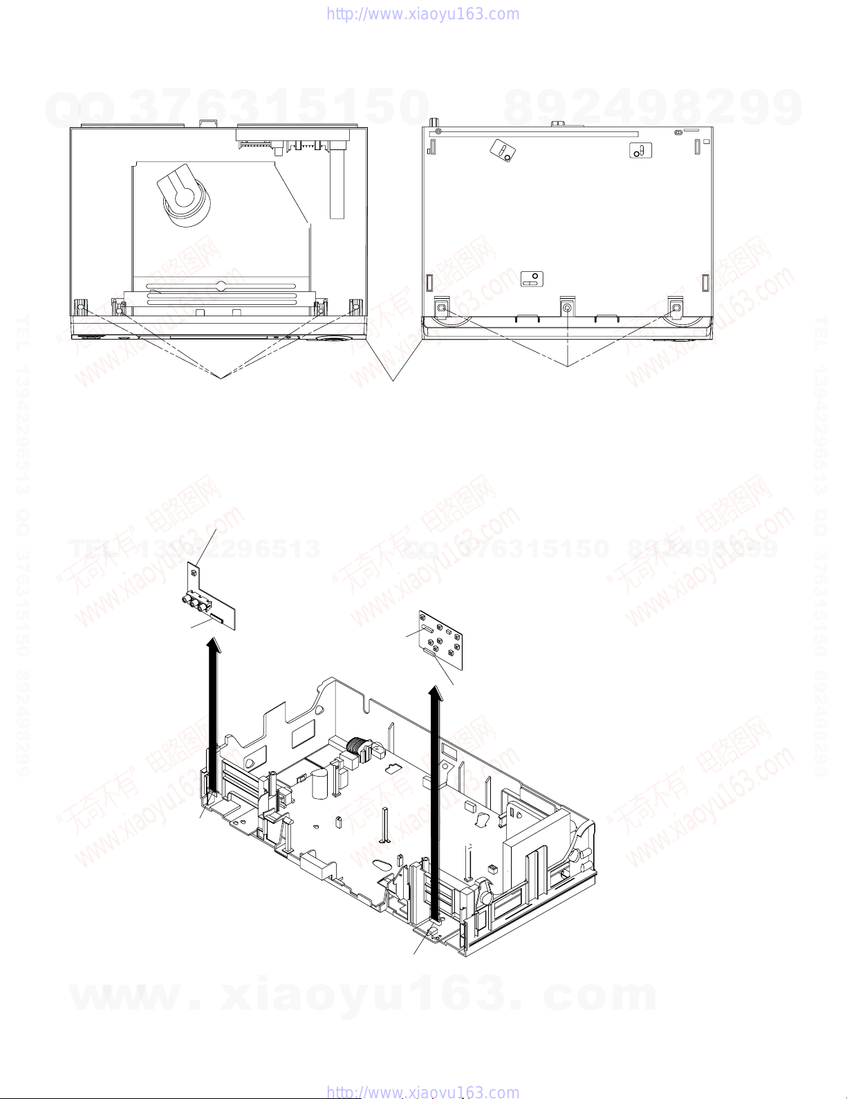
2-1-3 Ass’y-Panel Front
7
Q
Q
TEL 13942296513 QQ 376315150 892498299
2-1-4 Ass’y Jack PCB
3
6
1 RELEASE 4 HOOKS
(TOP VIEW)
3
1
5
1
5
0
ASS'Y-PANEL FRONT
Fig. 2-3 Ass’y-Panel Front
2
9
8
2 RELEASE 3 HOOKS
(BOTTOM VIEW)
4
9
8
2
9
9
TEL 13942296513 QQ 376315150 892498299
TEL
Disconnect the CN701 from the Ass'y PCB-Main and then lift the Ass'y PCB-Jack up.
13942296513
CN702
CN701
CN704
Q
Q
3
CN705
7
6
3
1
5
1
5
0
8
9
2
4
9
8
2
9
9
w
w
w
.
xia
CN703
o
y
u
1
6
Fig. 2-4 Ass’y Jack-PCB (Hi-Fi Models Only)
2-2
3
.
c
o
m
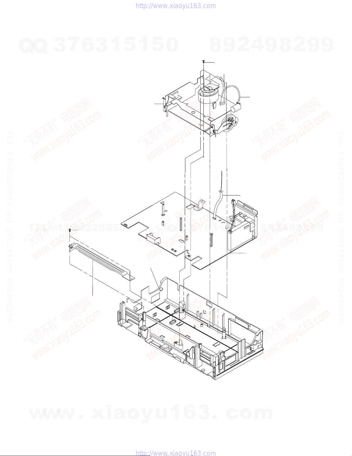
2-1-5 Ass’y MAIN-PCB, DECK
7
Q
Q
TEL 13942296513 QQ 376315150 892498299
3
6
3
1
8 ASS'Y-DECK
5
1
5
0
8
3 4 SCREWS
4 FLAT CABLE
9
4
2
5 FLAT CABLE
6 FLAT CABLE
9
8
2
9
9
TEL 13942296513 QQ 376315150 892498299
TEL
13942296513
1 2 SCREWS
2 BRACKET-FRAME
7 RELEASE 1 TAB
Q
Q
3
7
6
3
1
5
0
5
1
9 ASS'Y MAIN-PCB
8
9
2
4
9
8
2
9
9
w
w
w
.
xia
o
y
u
1
Fig. 2-5 Ass’y Main-PCB, Deck
6
2-3
3
.
c
o
m
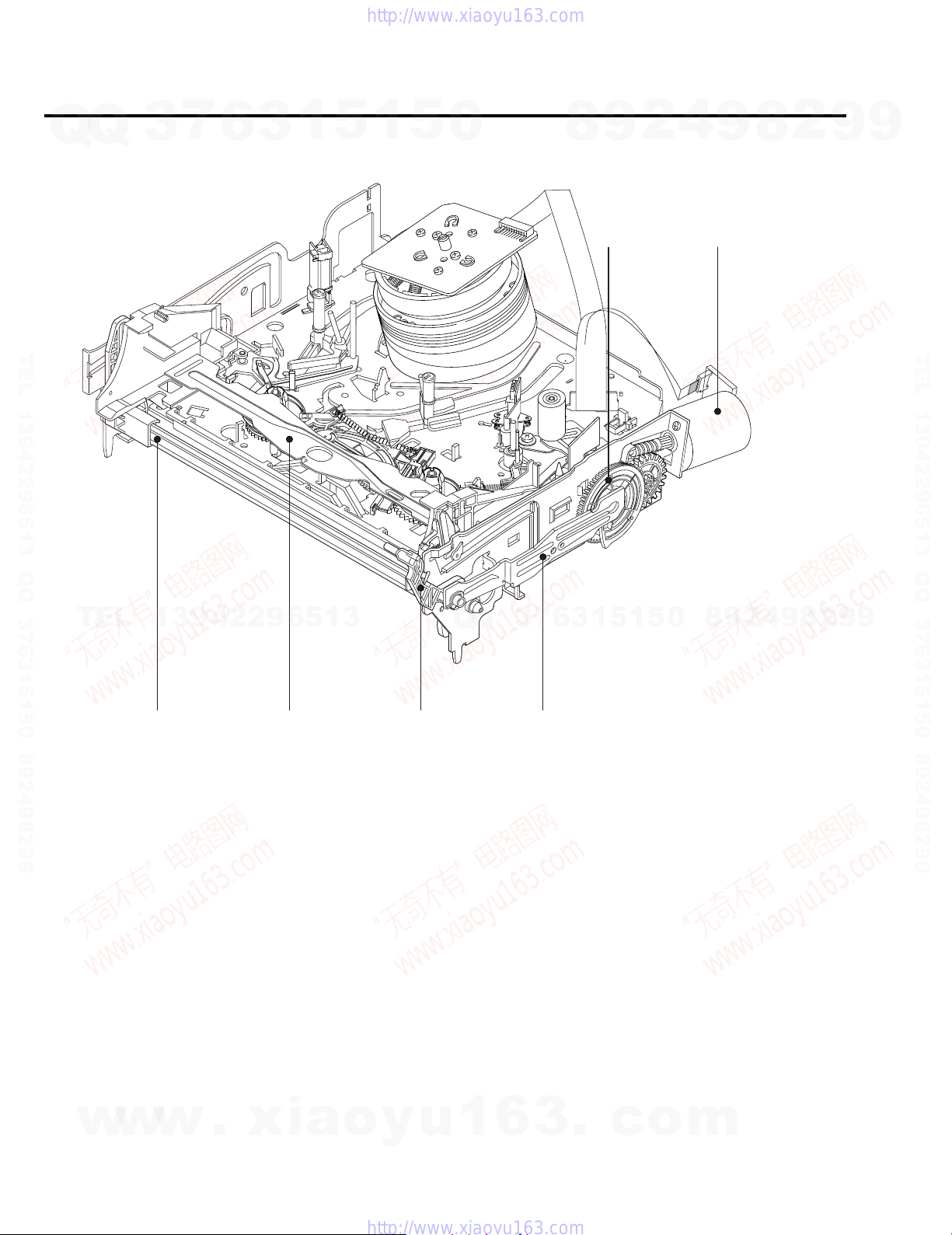
2-2 VCR DECK PARTS LOCATIONS
7
Q
Q
2-2-1 Top View
TEL 13942296513 QQ 376315150 892498299
3
6
3
1
5
1
5
0
8
9
1
2
4
9
2
8
2
9
9
TEL 13942296513 QQ 376315150 892498299
TEL
1 GEAR FL CAM
2 MOTOR LOADING ASS’Y
3 LEVER FL ARM ASS’Y
4 HOLDER FL CASSETTE ASS’Y
5 LEVER FL DOOR
6 SLIDER FL DRIVE
13942296513
3
4
Q
Q
5
Fig. 2-6 Top parts Location-1
3
7
6
6
3
1
5
1
5
0
8
9
2
4
9
8
2
9
9
w
w
w
.
xia
o
y
u
1
6
2-4
3
.
c
o
m
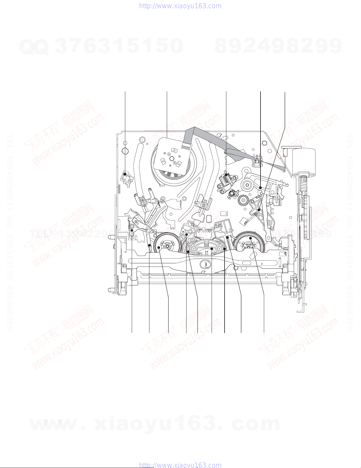
7
Q
Q
TEL 13942296513 QQ 376315150 892498299
3
6
3
1
1
5
1
5
2
0
4
2
9
8
34
9
5
8
2
9
9
TEL 13942296513 QQ 376315150 892498299
TEL
13942296513
6
1 FE HEAD
2 CYLINDER ASS’Y
3 ACE HEAD ASS’Y
4 LEVER UNIT PINCH ASS’Y
5 LEVER #9 GUIDE ASS’Y
6 LEVER TENSION ASS’Y
7 BAND BRAKE ASS’Y
5
1
5
1
3
6
7
3
Q
Q
789 qaq;qs
Fig. 2-7 Top Parts Location-2
8 DISK S REEL
9 LEVER S BRAKE ASS’Y
q; GEAR IDLE
qa LEVER IDLE
qs LEVER T BRAKE ASS’Y
qd DISK T REEL
q;
0
qd
8
9
2
4
9
8
2
9
9
w
w
w
.
xia
o
y
u
1
6
2-5
3
.
c
o
m
 Loading...