

Sony SLV-ED115, SLV-ED215, SLV-ED313, SLV-ED515, SLV-ED616 Service manual
...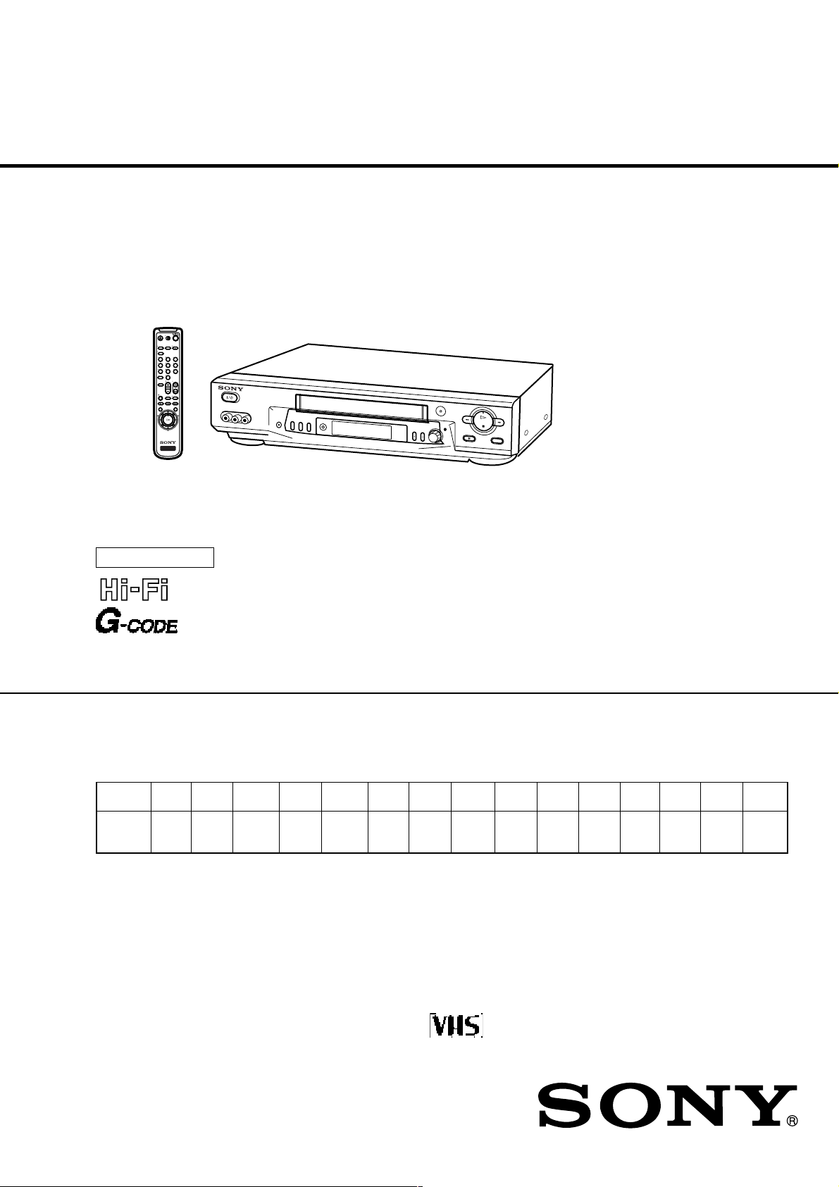
SLV-ED115/ED215/ED313/ED515/ED616/ED815/ED817/
ED818/ED915/ED919/EZ111/EZ212/EZ414/
EZ715/EZ717
RMT-V309/V311/V311A/V311B/V311C/V311D/V311E
SERVICE MANUAL
123
456
789
0
VIDEO
SLV-ED818
S MECHANISM
g
Australian Model
SLV-EZ111AZ/EZ212AZ/EZ414AZ/
EZ715AS/EZ717AS
E Model
SLV-ED115PS/ED215PS/ED515PS/
ED815PS//ED817PS/ED915PS
Hong Kong Model
SLV-ED919MI
ME Model
SLV-ED313ME/ED313MJ/ED313SG/
ED616ME/ED616MJ/ED616SG/
ED818ME/ED818SG
New Zealand Model
SLV-EZ715NZ/EZ717NZ
Thai Model
SLV-ED215TH/ED815TH/ED817TH/
ED915TH
• Refer to the SERVICE MANUAL of VHS MECHANICAL
ADJUSTMENTS VI for MECHANICAL ADJUSTMENTS.
(9-921-647-11)
* The abbreviations of ED115/ED215/ED313/ED515/ED616/ED815/
ED817/ED818/ED915/ED919/EZ111/EZ212/EZ414/EZ715 and EZ717
contained in this service manual are indicated when these models are
common to all their corresponding models as given below.
Abbreviated
model name
All model
names
SLV-
ED115
ED115PS
ED215 ED313
ED215PS
ED215TH
ED313ME
ED313MJ
ED313SG
ED515
ED515PS
ED616
ED616ME
ED616MJ
ED616SG
ED815 ED817
ED817PS
ED815PS
ED817TH
ED815TH
ED818ME
ED818SG
ED818
ED919
ED915
ED915PS
ED919MI EZ414AZ
ED915TH
EZ111
EZ111AZ
EZ212 EZ414
EZ212AZ
EZ715
EZ715AS
EZ715NZ
EZ717
EZ717AS
EZ717NZ
VIDEO CASSETTE RECORDER

SPECIFICATIONS
System
Color system
ED115/ED215/ED313/ED515/ED616/ED815/
ED817/ED818/ED915/ED919:
PAL, MESECAM, NTSC 3.58,
NTSC 4.43 (Others)
EZ111/EZ212/EZ414/EZ715/EZ717:
PAL, NTSC 4.43 (AS,AZ,NZ)
TV system
ED115/ED215/ED313/ED515/ED616/
ED815/ED817/ED818/ED915:
B/G, D/K, I
ED919:
B/G, D/K, I, M
EZ111/EZ212/EZ414/EZ715/EZ717:
B/G
Channel coverage
ED115/ED215/ED313/ED515/
ED616/ED815/ED817/ED818/ED915:
B/G: VHF E2 to E12/UHF E21 to E69/
CATV S01 to S05, S1 to S41
D/K: VHF R1 to R12/UHF R21 to R69
I: VHF SA4 to SA13/UHF B21 to B69/
CATV S01 to S05, S1 to S41
ED919MI:
M: VHF A2 to A13/UHF A14 to A69/
CATV A-8 to A-1, A to W, W+1 to W+ 84
EZ111/EZ212/EZ414/EZ715AS (COUNTRY
is set to AUS),
EZ717AS:
VHF AS0 to AS12, AS5A, AS9A
UHF AS28 to AS69
CATV S01 to S05, S1 to S41
EZ111/EZ212/EZ414/EZ715NZ (COUNTRY
is set to NZ),
EZ717NZ:
VHF NZ1 to NZ11
UHF E21 to E69
CATV S01 to S05, S1 to S41
RF output signal
ED115/ED215/ED313/ED515/ED616/
ED815/ED817/ED818/ED915/ED919/
EZ715NZ/EZ717NZ:
UHF channels 21 to 69
EZ111/EZ212/EZ414/EZ715AS/EZ717AS:
UHF channels 28 to 69
Aerial out
75-ohm asymmetrical aerial socket
Inputs and outputs
LINE-1 IN
VIDEO IN, phono jack (1)
Input signal: 1 Vp-p, 75 ohms, unbalanced,
sync negative
AUDIO IN (MONO), phono jack (1)
(ED115/ED215/ED313/ED515/ED616/
EZ111/EZ212/EZ414)
AUDIO IN, phono jack (2)
(ED815/ED817/ED818/ED915/ED919/
EZ717)
Input level: 327 mVrms
Input impedance: more than 47 kilohms
LINE-2 IN (ED515/ED616/ED818/ED915/
ED919/EZ715/EZ717)
VIDEO IN, phono jack (1)
Input signal: 1Vp-p, 75 ohms, unbalanced,
sync negative
AUDIO IN (MONO), phono jack (2)
(ED515/ED616)
AUDIO IN, phono jack (2) (ED818/ED915/
ED919/EZ715/EZ717)
Input level: 327mVrms
Input impedane: more than 47 kilohms
LINE-1 OUT
VIDEO OUT, phono jack (1)
Output signal: 1 Vp-p, 75 ohms, unbalanced, sync negative
AUDIO OUT (MONO), phono jack (1)
(ED115/ED215/ED313/EZ111/EZ212)
AUDIO OUT (MONO), phono jack (2)
(ED515/ED616/EZ414)
AUDIO OUT, phono jack (2)
(ED815/ED817/ED818/ED915/ED919/
EZ715/EZ717)
Standard output: 327 mVrms
Load impedance: 47 kilohms
Output impedance: less than 10 kilohms
General
Power requirements
110 - 240 V AC, 50/60 Hz (ED115/ED215/
ED313/ED515/ED616/ED815/ED817/
ED818/ED915/ED919) (Others)
220-240 V AC, 50 Hz (EZ111/EZ212/
EZ414/EZ715/EZ717)
Power consumption
13W (ED115/ED215/ED313/EZ111/
EZ212/EZ414)
14W (ED515/ED616/ED815/ED817/
ED818)
16W (ED915/ED919/EZ715/EZ717)
Operating temperature
5 ˚C to 40 ˚C
Storage temperature
–20 ˚C to 60 ˚C
Dimensions
Approx. 430 × 97 × 288 mm (w/h/d)
including projecting parts and controls
Mass
Approx. 4.1 kg:
Supplied accessories
Remote commander (1)
R6 (size AA) batteries (2)
Aerial cable (1)
Plug adaptor (1) (ED313: ME, MJ/ED616: ME,
MJ/ED818: ME)
Design and specifications are subject to change
without notice.
SAFETY CHECK-OUT
After correcting the original service problem, perform the following
safety checks before releasing the set to the customer:
1. Check the area of your repair for unsoldered or poorly-soldered connections. Check the entire board surface for solder
splashes and bridges.
2. Check the interboard wiring to ensure that no wires are
“pinched” or contact high-wattage resistors.
3. Look for unauthorized replacement parts, particularly transistors, that were installed during a previous repair. Point them
out to the customer and recommend their replacement.
SAFETY-RELATED COMPONENT WARNING!!
COMPONENTS IDENTIFIED BY MARK ! OR DOTTED
LINE WITH MARK ! ON THE SCHEMATIC DIAGRAMS
AND IN THE PARTS LIST ARE CRITICAL TO SAFE
OPERATION. REPLACE THESE COMPONENTS WITH
SONY PARTS WHOSE PART NUMBERS APPEAR AS
SHOWN IN THIS MANUAL OR IN SUPPLEMENTS PUBLISHED BY SONY.
4. Look for parts which, though functioning, show obvious signs
of deterioration. Point them out to the customer and recommend their replacement.
5. Check the B+ voltage to see it is at the values specified.
– 2 –
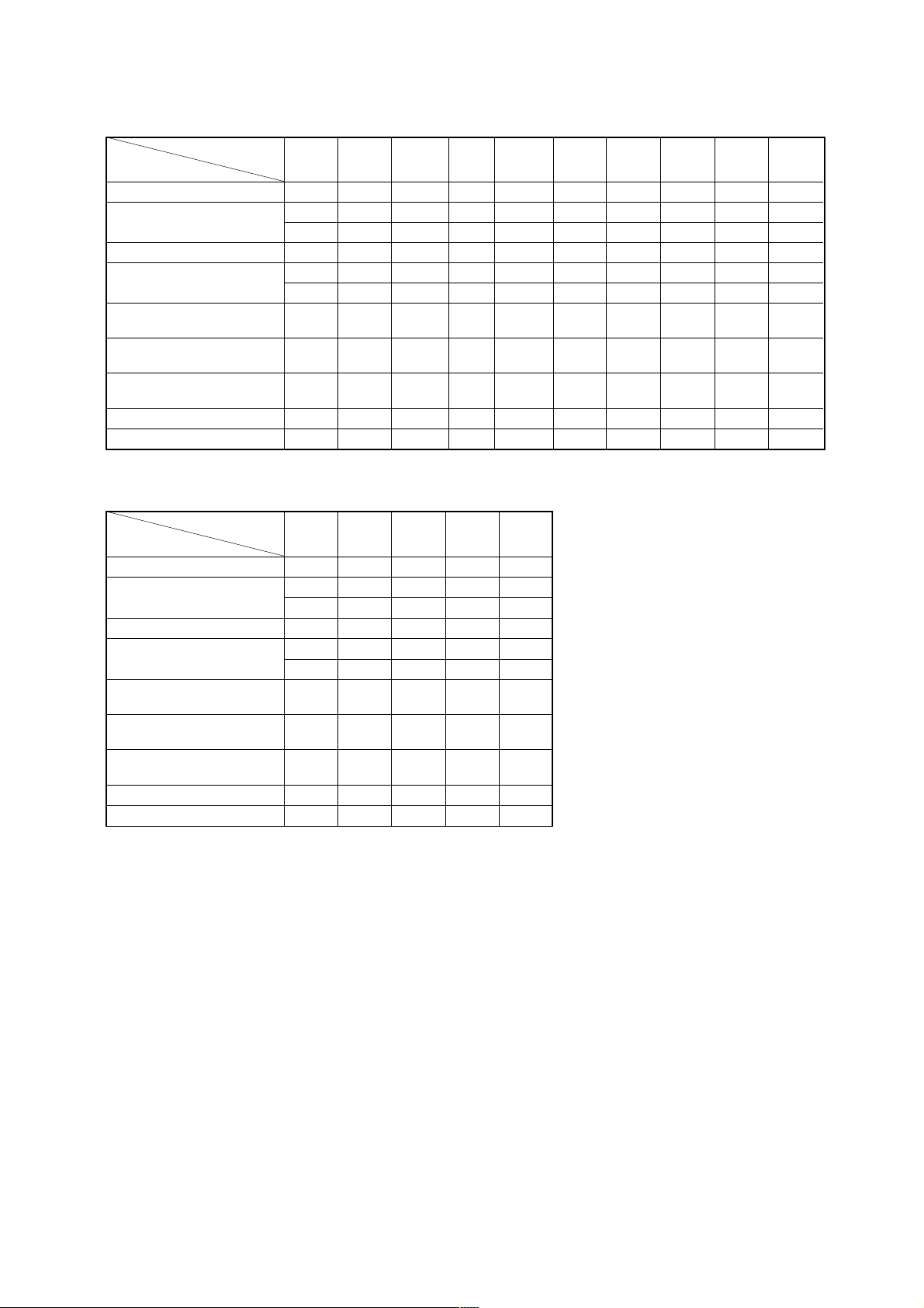
• Feature Difference
SLV- ED115 ED215 ED313 ED515 ED616 ED815 ED817 ED818 ED915 ED919
FEATURE PS PS, TH
HEAD/CH 2/2 2/2 2/2 2/2 4/4 4/4 4/6 4/6 4/6 4/6
NTSC (3.58) (REC/PB) a/aa/aa/aa/aa/aa/aa/aa/aa/aa/a
(4.43) (REC/PB) a/aa/aa/aa/aa/aa/aa/aa/aa/aa/a
ME-SECAM (REC/PB) a/aa/aa/aa/aa/aa/aa/aa/aa/aa/a
REC (NTSC) (SP/EP) aaaaa aaa aa
(PAL) (SP/LP) aaaaa aaa aa
RCA REAR LINE INPUT 2pin 2pin 2pin 2pin 2pin 3pin 3pin 3pin 3pin 3pin
(B.Y) (B.Y) (B.Y) (B.Y) (B.Y) (R.W.Y) (R.W.Y) (R.W.Y) (R.W.Y) (R.W.Y)
RCA REAR LINE OUTPUT 2pin 2pin 2pin 3pin 3pin 3pin 3pin 3pin 3pin 3pin
(B.Y) (B.Y) (B.Y) (B.B.Y) (B.B.Y) (R.W.Y) (R.W.Y) (R.W.Y) (R.W.Y) (R.W.Y)
RCA FRONT LINE INPUT ××××3pin 3pin ××3pin 3pin
MODULATOR SYSTEM G/K/I G/K/I G/K/I G/K/I G/K/I G/K/I G/K/I G/K/I G/K/I G/K/I/M
REMOTE COMMANDER RMT- V311 V311 V311 V311 V311B V311 V311A V311B V311A V311C
SLV- EZ111 EZ212 EZ414 EZ715 EZ717
FEATURE AZ AZ AZ AS, NZ AS, NZ
HEAD/CH 2/2 2/2 4/4 4/6 4/6
NTSC (3.58) (REC/PB) ×/××/××/××/× a/a
(4.43) (REC/PB) ×/a ×/a ×/a ×/aa/a
ME-SECAM (REC/PB) ×/××/××/××/××/×
REC (NTSC) (SP/EP) ×××× a
(PAL) (SP/LP) aaaa a
RCA REAR LINE INPUT 2pin 2pin 2pin 3pin 3pin
(B.Y) (B.Y) (B.Y) (R.W.Y) (R.W.Y)
RCA REAR LINE OUTPUT 2pin 2pin 3pin 3pin 3pin
(B.Y) (B.Y) (B.B.Y) (R.W.Y) (R.W.Y)
RCA FRONT LINE INPUT ×××3pin 3pin
MODULATOR SYSTEM G G G G G
REMOTE COMMANDER RMT- V311E V311D V311D V311E V309
SG, ME, MJ
PS
SG, ME, MJ
(Y.B.B) (Y.B.B) (Y.W.R) (Y.W.R)
(Y.W.R) (Y.W.R)
PS TH SG, ME PS, TH MI
– 3 –

TABLE OF CONTENTS
Section Title Page Section Title Page
Feature Difference ................................................................... 3
SERVICE NOTE ...................................................................... 5
1. GENERAL
Getting Started .............................................................. 1-1
Basic Operations ........................................................... 1-8
Search Operations ........................................................ 1-12
Additional Operations .................................................... 1-14
Additional Information ................................................... 1-16
2. DISASSEMBLY
2-1. Case Front Panel Block Assembly ................................ 2-1
2-2. DM-98, DI-81 Board and FJ-31 Board.......................... 2-1
2-3. Rear Panel..................................................................... 2-2
2-4. MA-402 Board ............................................................... 2-2
2-5. Mechanism Deck ........................................................... 2-3
2-6. Internal Views ................................................................ 2-4
2-7. Circuit Boards Location ................................................. 2-5E
5.
INTERFACE, IC PIN FUNCTION DESCRIPTION
5-1. System Control-Video Block Interface
(MA-402 BOARD IC101) ............................................... 5-1
5-2. System Control-Servo Peripheral Circuit Interface
(MA-402 BOARD IC101) ............................................... 5-1
5-3. System Control-Mechanism Block Interface
(MA-402 BOARD IC101) ............................................... 5-2
5-4. System Control-Audio Block Interface
(MA-402 BOARD IC101) ............................................... 5-3
5-5. Servo/System Control,
OSD Microprocessor Pin Function
(MA-402 BOARD IC101) ............................................... 5-4
5-6. NICAM Processor Pin Function
(NK-11 BOARD IC1) ..................................................... 5-5E
5-7. ZWEITON Processor Pin Function
(GK-12 BOARD IC001) ................................................. 5-5E
6. ERROR CODES .................................................... 6-1E
7. ADJUSTMENTS
3. BLOCK DIAGRAMS
3-1. Overall Block Diagram ................................................... 3-1
3-2. Video Block Diagram ..................................................... 3-3
3-3. Servo/System Control Block Diagram .......................... 3-5
3-4. Audio Block Diagram ..................................................... 3-7
3-5. Tuner Block Diagram ..................................................... 3-9
3-6. Mode Control Block Diagram ........................................ 3-11
3-7. Power Block Diagram .................................................... 3-13
4. PRINTED WIRING BOARDS AND
SCHEMATIC DIAGRAMS
4-1. Frame Schematic Diagram ............................................ 4-3
4-2. Printed Wiring Boards and Schematic Diagrams ......... 4-5
• MA-402 Printed Wiring Board .................................. 4-5
• MA-402 (Video, Audio) Schematic Diagram ............ 4-9
• MA-402 (System Control) Schematic Diagram ....... 4-13
• MA-402 (Servo Control) Schematic Diagram .......... 4-17
• MA-402 (Hi-Fi Audio) Schematic Diagram .............. 4-19
• MA-402 (Tuner) Schematic Diagram ....................... 4-21
• MA-402 (I/O) Schematic Diagram ............................ 4-23
• MA-402 (Mode Control) Schematic Diagram .......... 4-25
• MA-402 (Power Supply) Schematic Diagram .......... 4-27
• GK-12 Printed Wiring Board and
Schematic Diagram .................................................. 4-29
• NK-11 Printed Wiring Board and
Schematic Diagram .................................................. 4-31
• FJ-31 Printed Wiring Boards and
Schematic Diagrams ................................................ 4-33
• DM-98 Printed Wiring Boards and
Schematic Diagrams ................................................ 4-33
• DI-81 Printed Wiring Board and
Schematic Diagrams ................................................ 4-35E
7-1. Mechanical Adjustments ............................................... 7-1
7-2. Electrical Adjustments ................................................... 7-1
2-1. Pre-Adjustment Preparations ........................................ 7-1
2-1-1. Instruments to be Used ............................................ 7-1
2-1-2. Connection ............................................................... 7-1
2-1-3. Set-up of Adjustment ............................................... 7-1
2-1-4. Alingment Tapes ....................................................... 7-1
2-1-5. Specified I/O Level and Impedance ......................... 7-1
2-1-6. Adjusting Sequence ................................................. 7-2
2-2. Power Supply Adjustment ............................................. 7-2
2-2-1. Power Supply Check ................................................ 7-2
2-3. Servo System Adjustment ............................................. 7-2
2-3-1. RF Switching Position Adjustment ........................... 7-2
2-4. Audio System Adjustments ........................................... 7-3
2-4-1. Hi-Fi Audio System Adjustment ............................... 7-3
1. AF Switching Position Adjustment ........................... 7-3
2. Frequency Response Check .................................... 7-3
3. Overall Level Characteristic and
Distortion Factor Check ........................................... 7-4
4. Overall S/N Check .................................................... 7-4
2-4-2. Normal Audio System Adjustment ........................... 7-4
1. ACE Head Adjustment ............................................. 7-4
2. E-E Output Level Check ........................................... 7-4
3. Frequency Responce Check .................................... 7-4
4. Overall Level Characteristic and Distortion
Factor Check ............................................................ 7-5
5. Overall S/N Check .................................................... 7-5
2-5. Tuner System Adjustment ............................................. 7-5
2-5-1. Separation Adjustment ............................................. 7-5
2-6. Parts Arrangement Diagram for Adjustments ............... 7-6E
8. REPAIR PARTS LIST
8-1. Exploded Views ............................................................. 8-1
8-1-1. Front Panel and Upper Case Section ...................... 8-1
8-1-2. Chassis Section ....................................................... 8-3
8-1-3. Mechanism Deck Section-1 ..................................... 8-5
8-1-4. Mechanism Deck Section-2 ..................................... 8-6
8-1-5. Mechanism Deck Section-3 ..................................... 8-7
8-2. Electrical Parts List ....................................................... 8-8
– 4 –
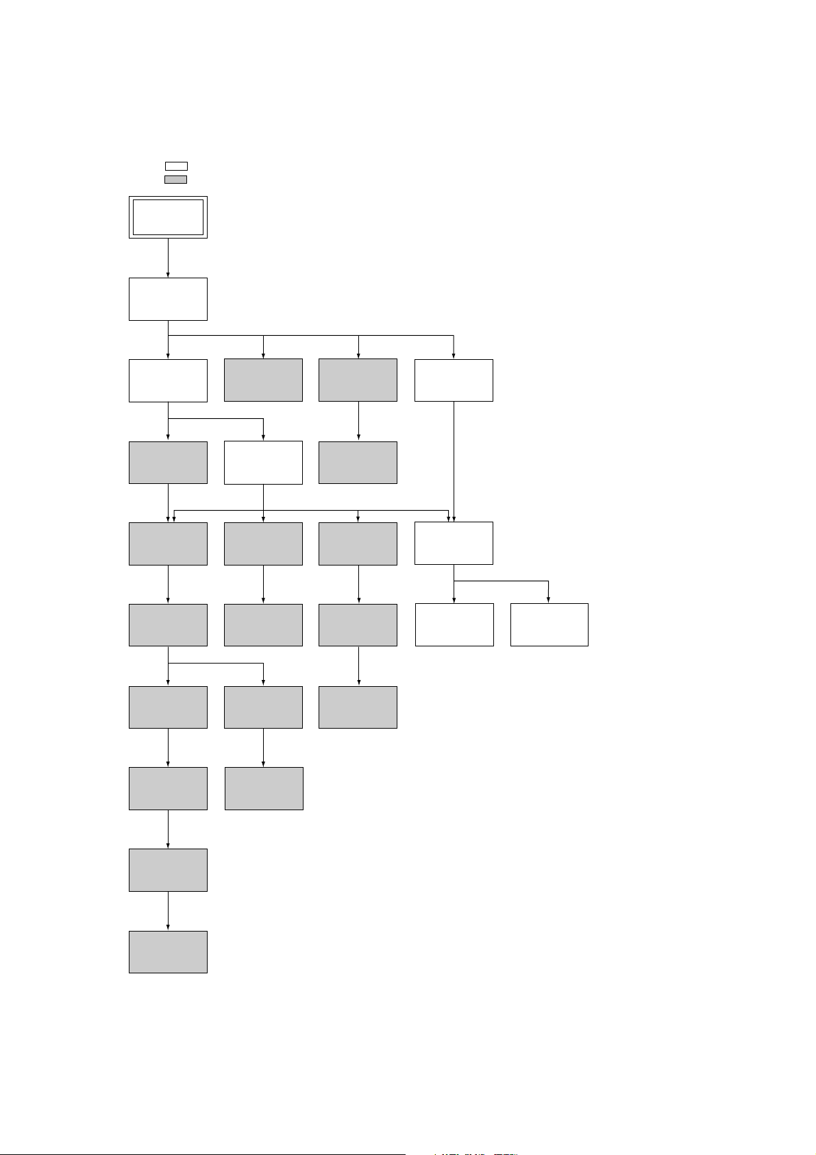
SERVICE NOTE
1. DISASSEMBLY
• This set can be disassembled in the order shown below.
Note: Pages in indicated pages in the SERVICE MANUAL.
Pages in indicated pages in the VHS MECHANICAL ADJUSTMENT MANUAL VI.
Set
Upper case
(Page 2-1)
Front Panel
Section
(Page 2-1)
FL Complete
Ass’y
(Page 13)
Retainer
Plate
(Page 22)
FL Slider
Block Ass’y
(Page 22)
Cam Gear
(Page 23)
Pinch Press
Block Ass’y
(Page 14)
Mechanism
Deck
(Page 2-3)
Rubber
Belt
(Page 15)
Capstan
Motor
(Page 15)
Cam Motor
Retainer
(Page 31)
Ground Shaft
Ass’y
(Page 13)
Drum
Ass’y
(Page 13)
Rubber
Belt
(Page 15)
Pully Gear
Ass’y
(Page 29)
Reel Direct
Ass’y
(Page 30)
Rear
Panel
(Page 2-2)
MA-402
Board
(Page 2-2)
Rotary
Switch
(Page 2-3)
Tuner
Unit
Rubber
Belt
(Page 15)
Slider
(Page 26)
Loading
Gear (T, S)
(Page 28)
Cam Motor
(Page 31)
– 5 –
PROGRAM
SLV-ED115/ED215/ED313/ED515/ED616/ED815/ED817/ED818/ED915/ED919/EZ111/
EZ212/EZ414/EZ715/EZ717
SECTION 1
GENERAL
This section is extracted from
SLV-ED919MI Instruction Manual.
(3-065-580-11)
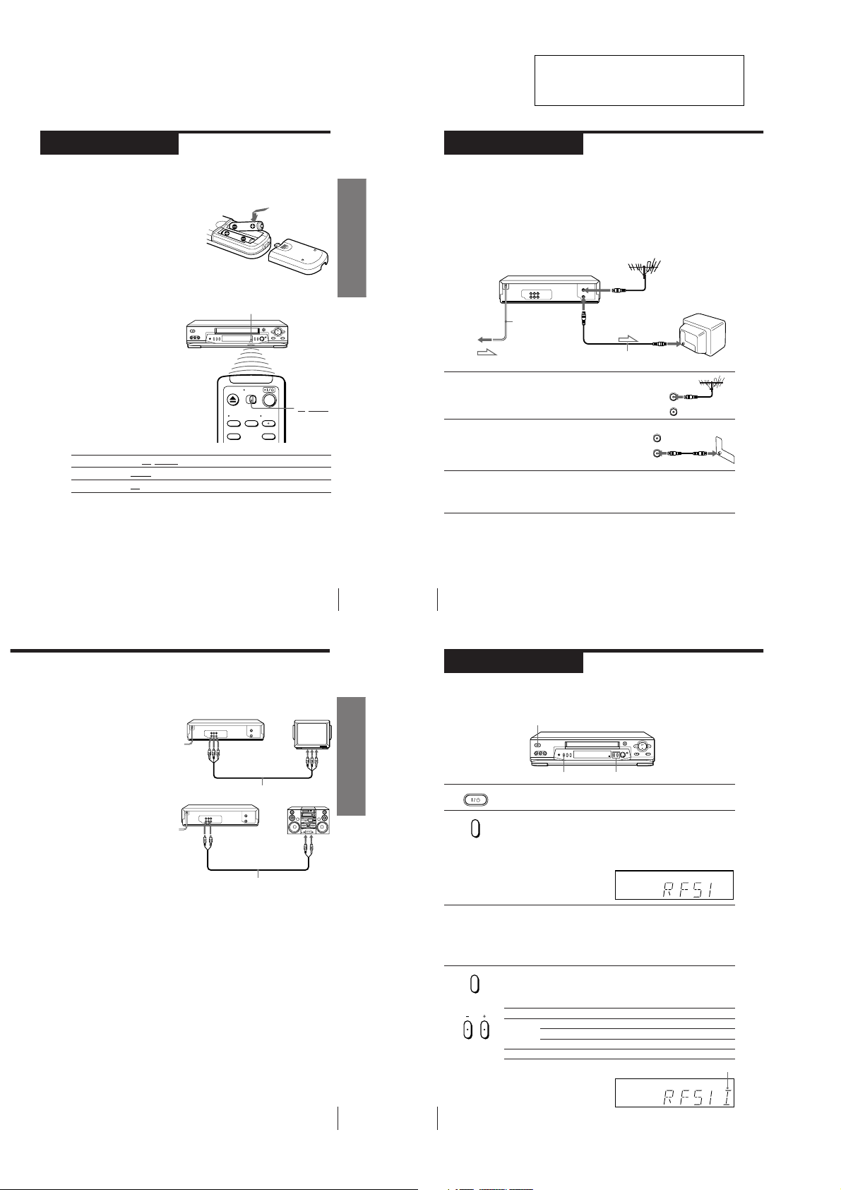
Step 2
Setting up the remote commander
Inserting the batteries
Insert two R6 (size AA) batteries by
matching the + and – on the batteries
to the diagram inside the battery
compartment.
Insert the negative (–) end first, then
push in and down until the positive
(+) end clicks into position.
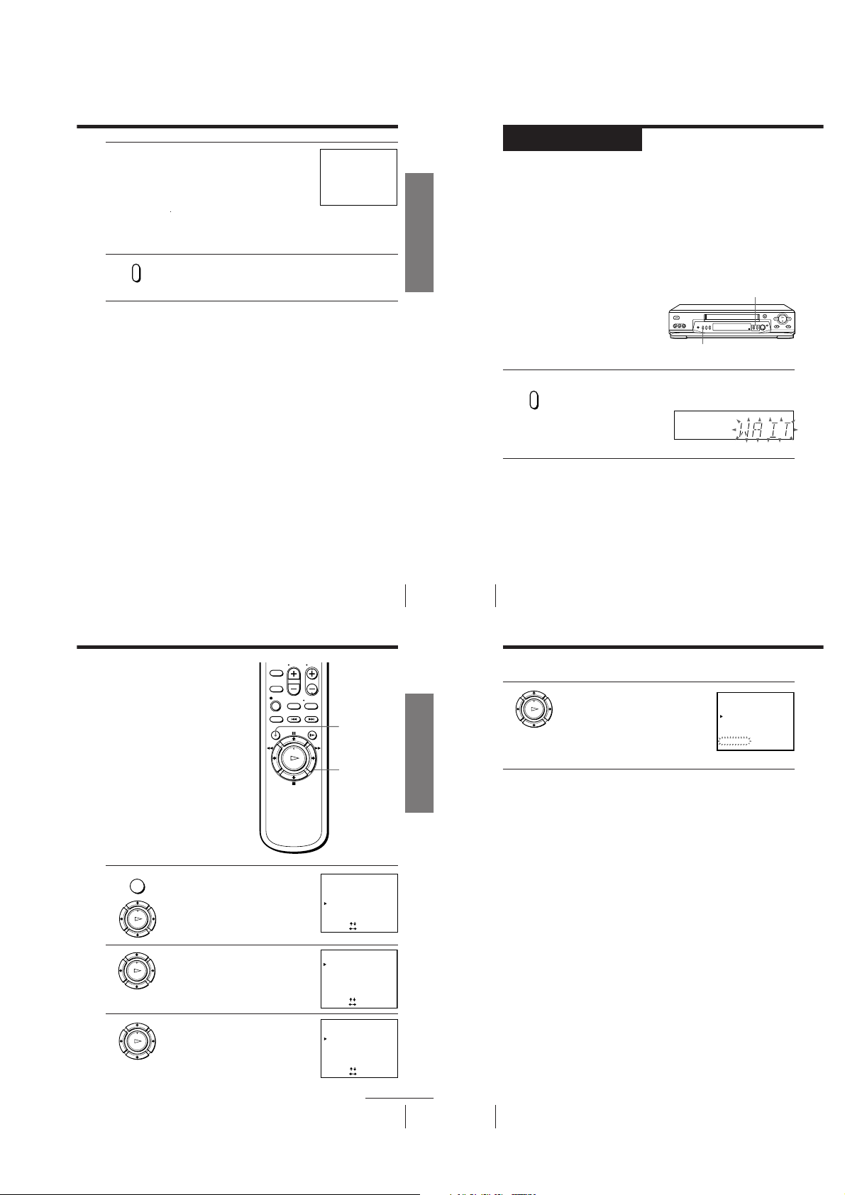
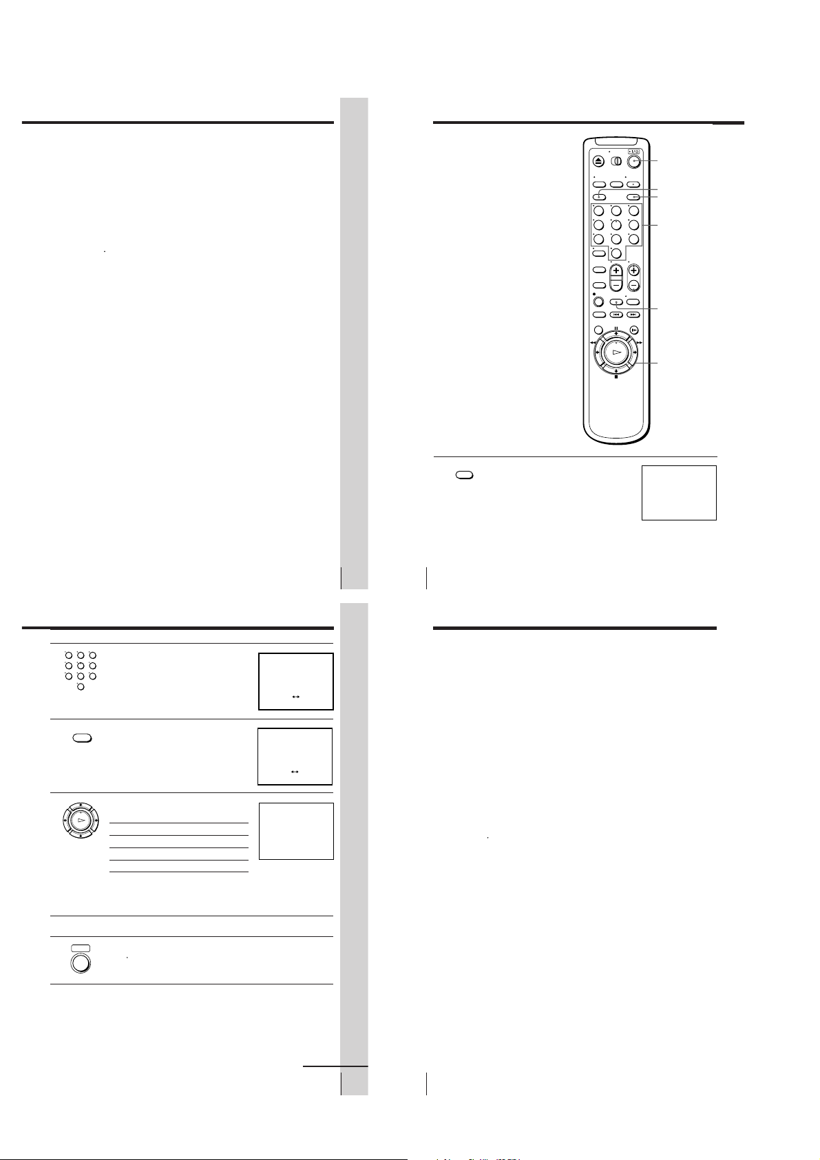
Using the remote commander
You can use this remote
commander to operate this
VCR and a Sony TV. Buttons
on the remote commander
marked with a dot (•) can be
used to operate your Sony TV.
If the TV does not have the g
symbol near the remote sensor,
this remote commander will
not operate the TV.
To operate
the VCR
a Sony TV
Notes
• The TV/VIDEO button selects the TV’s input source (either aerial in or line in). The
button does not control this VCR.
• With normal use, the batteries should last about three to six months.
• If you do not use the remote commander for an extended period of time, remove
the batteries to avoid possible damage from battery leakage.
• Do not use a new battery with an old one.
• Do not use different types of batteries.
Set
VIDEO
TV
to
TV/VIDEO
and point at the remote sensor on the VCR
and point at the remote sensor on the TV
Remote sensor
TV/VIDEO
Getting Started
Step 3
Connecting the VCR
Connect the aerial to your VCR and TV as shown below to watch TV
programmes and VCR pictures on your TV. In addition, if your TV has
audio/video (A/V) input jacks, we recommend you connect the VCR to
your TV using an audio/video cable to get a better picture and sound.
Connecting the aerial
AERIAL OUT
Mains lead
to mains
1 Disconnect the aerial cable from your TV
2 Connect AERIAL OUT of the VCR and
: Signal flow
and connect it to AERIAL IN on the rear
panel of the VCR.
the aerial input of your TV using the
supplied aerial cable.
AERIAL IN
AERIAL IN
Aerial cable (supplied)
3 Connect the mains lead to the mains.
If the 3-pin plug does not fit into the mains outlet, detach the plug
by loosening the screw, then use the 2-pin plug inside.
AERIAL
AERIAL
IN
OUT
IN
OUT
Additional connections
Note
• To play a tape in stereo, you must use either
one of the connections shown below.
To a TV that has audio/video input jacks
This additional connection improves
picture and sound quality. Connect the
TV as shown on the right.
To a stereo system
You can improve sound quality by
connecting a stereo system as shown on
the right.
Getting Started
LINE OUT
Audio/video cable (not supplied)
LINE AUDIO OUT
Audio cable (not supplied)
LINE IN
LINE IN
5
Getting Started
Getting Started
6
Step 4
Tuning your TV to the VCR
If you have connected your VCR to the TV using the audio/video cable, skip
this step.
?/1 ON/STANDBY
ON/STANDBY
1 Press ?/1 ON/STANDBY to turn on the VCR.
2 Press RF CHANNEL on the VCR.
3
4 Press RF CHANNEL.
The factory-preset RF channel flashes in the display window for
RF CHANNEL
about three seconds.
Press RF CHANNEL again while the RF channel is flashing.
The VCR signal is output through this channel to the TV.
Turn on your TV and select a programme position for the VCR picture.
This channel will now be referred to as the video channel.
Some TVs reserve a programme position, such as “0”, for a VCR. In
this case, select the reserved programme position for the VCR
picture. Refer to your TV’s instruction manual for details.
The TV system indicator appears in the display window.
RF CHANNEL
Press PROGRAM +/– to select the correct TV system.
If your TV colour system and TV system are Select
PAL I I
D/K K
B/G G
NTSC M M
PROGRAM +/–RF CHANNEL
SP
SP
APC
Selected TV system
APC
Getting Started
Getting Started
7
8
1-1
5 Tune the TV to the same channel as
SP
APC
TUNER PRESET PROG 1
NORMAL / CATV
SYSTEM
AUTO PRESET
CHANNEL SET
NORM
ON••
CATV
B / G
•
D / K
MI
OFF
1
AFT
FINE TUNING
PLEASE WAIT
shown in the display window so that
the picture on the right appears on the
TV screen.
Refer to your TV manual for tuning
instructions.
If you select the wrong TV system in step 4, the picture may not
appear. Select the appropriate TV system and tune the TV again.
If the picture does not appear clearly, see “To obtain a clear picture
from the VCR” below.
6 Press RF CHANNEL.
RF CHANNEL
You have now tuned your TV to the VCR. From now on, whenever
you want to play a tape, set the TV to the video channel.
To obtain a clear picture from the VCR
If the picture does not appear clearly in step 5 above, first go to step 6 to
finish this procedure once. Then start from step 2. After pressing RF
CHANNEL twice in step 2 to display the RF channel, press PROGRAM +/–
so that another RF channel appears. Then tune the TV to the new RF channel
until a clear picture appears.
To set another RF channel number on the VCR, select a channel number that
does not receive a broadcast signal in your area and is clear of interference
from other channels.
If you cannot obtain a clear picture after performing this procedure, we
recommend you connect the VCR and TV using the audio/video cable (see
“To a TV that has audio/video input jacks” on page 7). If the same symptom
persists, consult your nearest Sony dealer.
Note
• If you set the wrong TV system, you may have no sound or sound may be distorted
(noisy sound).
SONY VIDEO CASSETTE
RECORDER
Getting Started
Getting Started
9
Step 5
Presetting channels
First, we recommend that you preset the receivable channels in your area
using the One Touch Tuning function or AUTO PRESET in the TUNER
PRESET menu. Then, if some channels cannot be preset automatically, set
them manually. If there are any unwanted channels among the preset ones,
you can disable the channels.
If you live in the area where various TV systems coexist, and have channels
that do not match the TV system you selected in automatic presetting, reset
the TV system for those channels (see “Resetting the TV system” on page
15). If the channels do not match the TV system, the sound may be distorted
or noisy, or the colour TV programme may become black and white, etc.
Presetting all receivable
channels using the One
Touch Tuning function
ONE TOUCH
Press and hold ONE TOUCH TUNING on the VCR for more than
TUNING
three seconds.
The VCR starts presetting the channels.
The WAIT indicator goes off when all receivable channels are preset.
To check if the channels are preset correctly
Set the TV to the video channel and press PROGRAM +/– on the VCR.
If the TV screen changes to a different programme each time you press
PROGRAM +/–, the channels are preset correctly.
If the sound is distorted or noisy, the VCR is set to a TV system different
from your area’s system. Select the correct TV system and preset channels
using the TUNER PRESET menu as shown on the next page.
Tip
• To stop the One Touch Tuning function, press ONE TOUCH TUNING or x STOP
on the VCR during the setting.
Getting Started
10
ONE TOUCH
TUNING
PROGRAM +/–
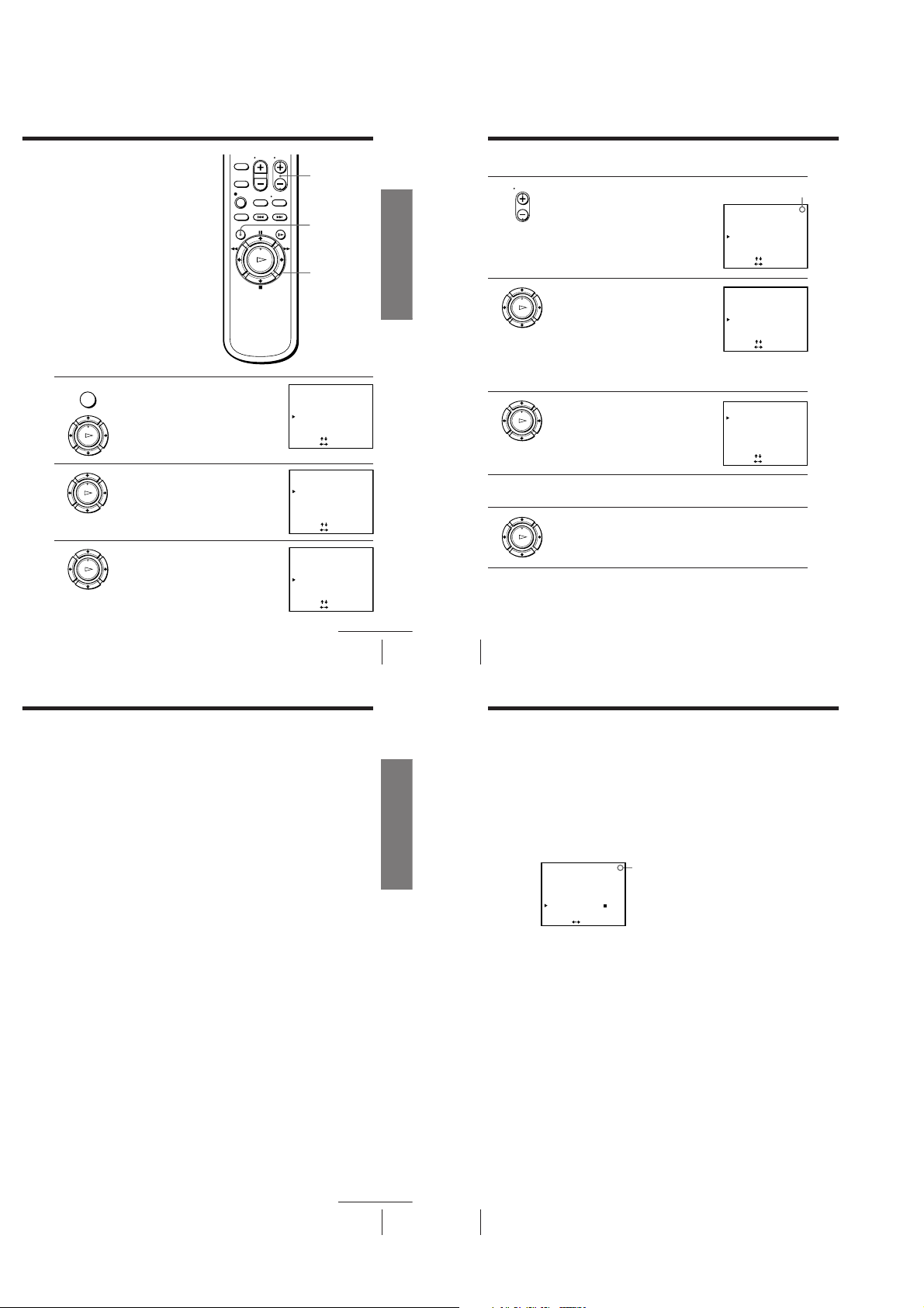
Presetting all receivable
channels automatically
Before you start…
• Turn on the VCR and the TV.
• Set the TV to the video channel.
MENU
1 Press MENU, then press M/m to move the
2 Press M/m/</, to move the cursor (B)
3 Press M/m/</, to move the cursor
cursor (B) to TUNER PRESET and press
OK.
PLAY
OK
PLAY
to SYSTEM, then select B/G, D/K, I or M,
whichever is applicable in your area. If
OK
SYSTEM is set to the wrong position, the
sound will be distorted or noisy.
(B) to NORMAL/CATV, then select
PLAY
NORM.
OK
To preset CATV channels, select CATV.
MENU
OK
M/m/</,
TUNER PRESET PROG 1
SYSTEM
NORMAL / CATV
AUTO PRESET
CHANNEL SET
AFT
FINE TUNING
SELECT
SET
TUNER PRESET PROG 1
SYSTEM
NORMAL / CATV
AUTO PRESET
CHANNEL SET
AFT
FINE TUNING
SELECT
SET
TUNER PRESET PROG 1
SYSTEM
NORMAL / CATV
AUTO PRESET
CHANNEL SET
AFT
FINE TUNING
SELECT
SET
•
[]
:
[
:
•
[]
:
[
:
•
[]
:
[
:
B / G
D / K
CATV
NORM
1
ON••
]
B / G
D / K
CATV
NORM
1
ON••
]
B / G
D / K
CATV
NORM
1
ON••
]
continued
Getting Started
MI
OFF
MI
OFF
MI
OFF
Getting Started
11
Step 5: Presetting channels (continued)
4 Press M/m to move the cursor (B) to
Getting Started
12
AUTO PRESET, then press OK.
PLAY
OK
All receivable channels are preset in
numerical sequence. When no more
receivable channels can be found,
presetting stops and the picture from the
lowest numbered channel is displayed on
the TV screen.
Notes
• Picture might disappear for a few seconds during One Touch Tuning and auto
presetting functions. This is for tuning procedure, and not a malfunction.
• The channel numbers in the CHANNEL SET column may not be the same as those
in your area. This is because this VCR’s channel search system is based on the fixed
TV system that has the widest channel coverage. If necessary, apply your local
channel numbers to the programme positions (see “Presetting channels manually”
on page 13).
• If the received channel is on cable TV, “C” appears on the left of the channel in step
4 in most areas. However, this will not be applied in some areas (see pages 17 to 24
for reference).
1-2
Presetting channels
OK
PLAY
OK
PLAY
OK
PLAY
manually
Before you start…
• Turn on the VCR and the TV.
• Set the TV to the video channel.
MENU
1 Press MENU, then press M/m to move the
2 Press M/m/</, to move the cursor (B)
3 Press >/. to move the cursor (B) to
cursor (B) to TUNER PRESET and press
OK.
PLAY
OK
to NORMAL/CATV, then select NORM.
PLAY
OK
To preset CATV channels, select CATV.
PLAY
CHANNEL SET.
OK
PROG +/–
MENU
OK
M/m/</,
TUNER PRESET PROG10
SYSTEM
NORMAL / CATV
AUTO PRESET
CHANNEL SET
AFT
FINE TUNING
SELECT
SET
TUNER PRESET PROG10
SYSTEM
NORMAL / CATV
AUTO PRESET
CHANNEL SET
AFT
FINE TUNING
SELECT
SET
TUNER PRESET PROG10
SYSTEM
NORMAL / CATV
AUTO PRESET
CHANNEL SET
AFT
FINE TUNING
SELECT
SET
• D / K
[]
:
[
:
•
[]
:
[
:
•
[]
:
[
:
B / G
NORM
21
ON••
]
B / G
D / K
NORM
21
ON••
]
B / G
D / K
NORM
21
ON••
]
continued
Getting Started
CATV
CATV
CATV
MI
OFF
MI
OFF
MI
OFF
Getting Started
13
Step 5: Presetting channels (continued)
PROG
4 Press PROG +/– to select the programme
5 Press , repeatedly until the channel you
6 If the TV sound is distorted or noisy, press
7 To allocate another channel to another programme position, repeat
position.
want is displayed.
Pressing < goes back to the previous
channels.
The channels are scanned in the order
shown on page 17 to 24.
If you know the number of the channel you want, press the
programme number buttons. For example, for channel 5, first press
“0” and then press “5”.
M/m/</, to move the cursor (B) to
SYSTEM, then select B/G, D/K, I or
M, whichever is applicable in your area.
steps 4 and 5.
Selected programme
position
TUNER PRESET PROG14
SYSTEM
NORMAL / CATV
AUTO PRESET
CHANNEL SET
AFT
FINE TUNING
SELECT
SET
TUNER PRESET PROG14
SYSTEM
NORMAL / CATV
AUTO PRESET
CHANNEL SET
AFT
FINE TUNING
SELECT
SET
TUNER PRESET PROG14
SYSTEM
NORMAL / CATV
AUTO PRESET
CHANNEL SET
AFT
FINE TUNING
SELECT
SET
8 Press OK.
Getting Started
14
•
[]
:
[
:
•
[]
:
[
:
•
[]
:
[
:
B / G
D / K
MI
CATV
NORM
21
ON••
OFF
]
B / G
D / K
MI
NORM
CATV
35
OFF
ON••
]
B / G
D / K
MI
NORM
CATV
35
OFF
ON••
]
Disabling unwanted programme positions
After presetting channels, you can disable unused programme positions. The
disabled positions will be skipped later when you press the PROG +/–
buttons.
1 In step 5 on page 14, press programme number button “0” twice to
display the number “0” beside CHANNEL SET.
2 Press OK.
Resetting the TV system (only for areas where
various TV systems coexist)
If the sound is distorted or noisy, or the colour TV programme becomes
black and white, etc., that channel may not be matched to the proper TV
system. In this case, try the following steps.
1 Press PROG +/– or programme number buttons to select the
programme position that has the channel with above described
conditions.
2 Press MENU, then select TUNER PRESET and press OK.
3 Select SYSTEM and select the TV system on which you can obtain the
best sound and picture.
4 Repeat steps 2 and 3 for other positions you want to reset the TV
system to.
5 Press OK.
Getting Started
Step 5: Presetting channels (continued)
If the picture is not clear
Normally, the Auto Fine Tuning (AFT) function automatically tunes in
channels clearly. If, however, the picture is not clear, you may also use the
manual tuning function.
1 Press PROG +/– to select the programme number for which you cannot
obtain a clear picture.
2 Press MENU, then select TUNER PRESET and press OK.
3 Select FINE TUNING.
The fine tuning meter appears.
:
•
[
D / K
NORM
ON••
– – – –– – – –
]
PROG14
Selected programme position
B / G
MI
CATV
5
3
OFF
TUNER PRESET
SYSTEM
NORMAL / CATV
AUTO PRESET
CHANNEL SET
AFT
FINE TUNING
SET
4 Press </, to get a clearer picture, then press OK.
Note that the AFT (Auto Fine Tuning) setting switches to OFF.
Notes
• The menu disappears automatically if you do not proceed for more than a few
minutes.
• The channel numbers in the CHANNEL SET column may not be the same as those
in your area. This is because this VCR’s channel search system is based on the fixed
TV system that has the widest channel coverage. If necessary, apply your local
channel numbers to the programme positions (see “Presetting channels manually”
on page 13).
continued
Getting Started
15
1-3
Getting Started
16
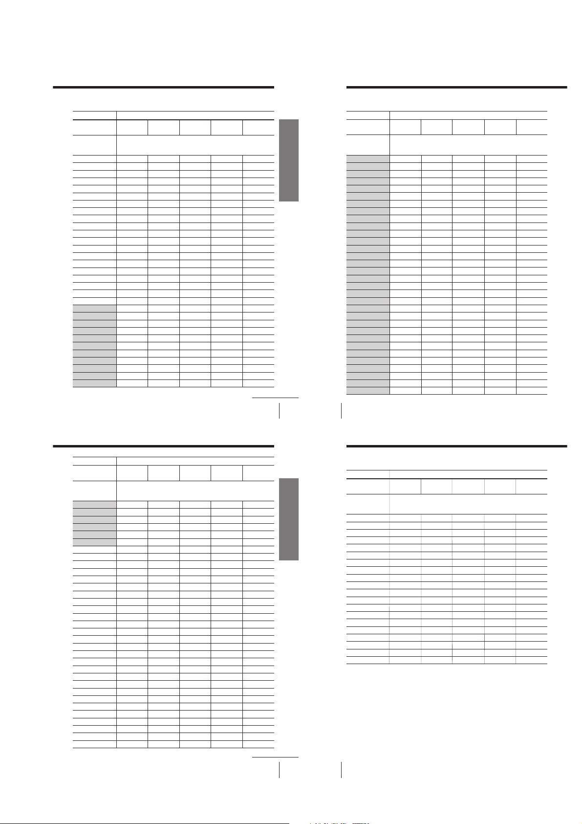
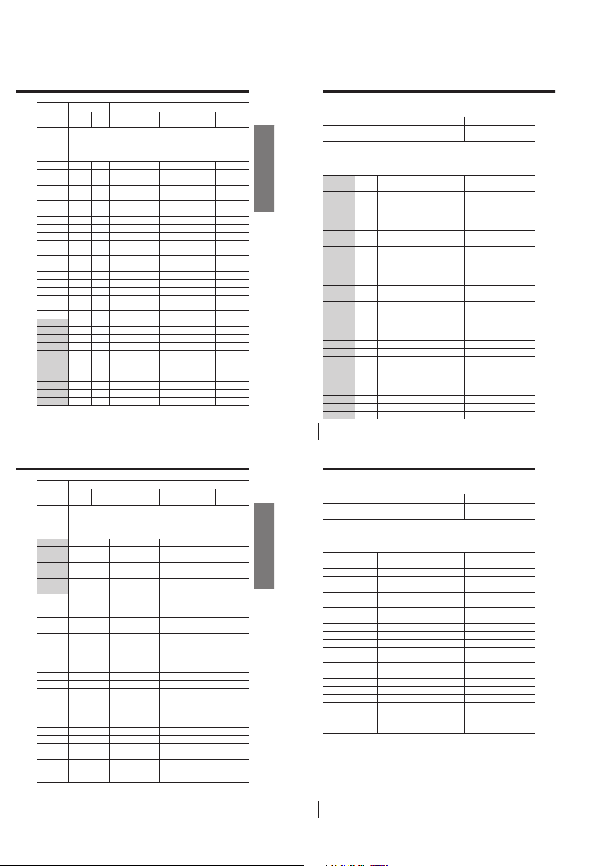
Channel numbers in the CHANNEL SET field and the corresponding channels
TV system
Country
Channel number
in the CHANNEL
SET column
1
2
3
4
5
6
7
8
9
10
11
12
13
14
15
16
17
18
19
20
21
22
23
24
25
26
27
28
29
30
31
Europe
E2
E3
E4
E5
E6
E7
E8
E9
E10
E11
E12
E21
E22
E23
E24
E25
E26
E27
E28
E29
E30
E31
Australia New
AS0
9A
10
11
28
29
30
31, 32
B/G
Zealand
Corresponding channels
1
1
2
6
7
8
9
3
4
2
3
4
5
6
7
8
9
10
11
Morocco
M6
M7
M8
M9
M10
IndonesiaWestern
continued
Getting Started
10A
11A
1A
2A
3A
4A
5A
6A
7A
8A
9A
Getting Started
17
Step 5: Presetting channels (continued)
TV system
Getting Started
18
Country
Channel number
in the CHANNEL
SET column
Western
32
33
34
35
36
37
38
39
40
41
42
43
44
45
46
47
48
49
50
51
52
53
54
55
56
57
58
59
60
61
62
63
Europe
E32
E33
E34
E35
E36
E37
E38
E39
E40
E41
E42
E43
E44
E45
E46
E47
E48
E49
E50
E51
E52
E53
E54
E55
E56
E57
E58
E59
E60
E61
E62
E63
Australia New
B/G
Zealand
Corresponding channels
33
34
35
36
37
38
39, 40
41
42
43
44
45
46
47, 48
49
50
51
52
53
54
55, 56
57
58
59
60
61
62
63, 64
65
66
67
68
Morocco
Indonesia
TV system
Country
Channel number
in the CHANNEL
SET column
64
65
66
67
68
69
70
C1
C2
C3
C4
C5
C6
C7
C8
C9
C10
C11
C12
C13
C14
C15
C16
C17
C18
C19
C20
C21
C22
C23
C24
C25
C26
Western
Europe
E64
E65
E66
E67
E68
E69
S1
S2
S3
S4
S5
S6
S7
S8
S9
S10
S11
S12
S13
S14
S15
S16
S17
S18
S19
S20
S21
S22
S23
S24
S25
S26
Australia New
Zealand
Corresponding channels
69
5
5A
B/G
Morocco
M4
M5
Indonesia
continued
Getting Started
Getting Started
19
Step 5: Presetting channels (continued)
TV system
Getting Started
20
Country
Channel number
in the CHANNEL
SET column
C27
C28
C29
C30
C31
C32
C33
C34
C35
C36
C37
C38
C39
C40
C41
C42
C43
C44
C45
C46
Western
Europe
S27
S28
S29
S30
S31
S32
S33
S34
S35
S36
S37
S38
S39
S40
S41
S01
S02
S03
S04
S05
Australia New
B/G
Zealand
Morocco
Corresponding channels
Indonesia
1-4
TV system
Country
Channel
number in
the
CHANNEL
SET column
1
2
3
4
5
6
7
8
9
10
11
12
13
14
15
16
17
18
19
20
21
22
23
24
25
26
27
28
29
30
31
East
Europe
R1
R6
R7
R12
R2
R3
R4
R5
R8
R9
R10
R11
R21
R22
R23
R24
R25
R26
R27
R28
R29
R30
R31
D/K
China
1
2
3
7
8
4
5
9
10
11
12
13
14
15
16
17
18
19
20
21
22
23
IM
Ireland U.S.A.
UK/Hong
Kong
South
Africa
Corresponding channels
A
B
C
D
E
J
F
G
H
I
B21
B22
B23
B24
B25
B26
B27
B28
B29
B30
B31
4
5
10
6
7
8
9
21
22
23
24
25
26
27
28
29
30
31
2, C2
3
7
8
9
12
13
J
K
5
10
11
14, W+29, W+30
15, 16, W+31
17, W+32
18, W+33, W+34
19, 20, W+35
21, W+36
22, W+37, W+38
23, 24, W+39
25, W+40
26, W+41, W+42
27, 28, W+43
Japan
J-5
J-6
J-7
J-10
J-11
J-12
S1
J-8
J-9
J13
J14, J15
J16
J17
J18, J19
J20
J21
J22, J23
J24
J25
J26, J27
continued
Getting Started
Getting Started
21
Step 5: Presetting channels (continued)
Getting Started
22
TV system
Country
Channel
number in
the
CHANNEL
SET column
32
33
34
35
36
37
38
39
40
41
42
43
44
45
46
47
48
49
50
51
52
53
54
55
56
57
58
59
60
61
62
East
Europe
R32
R33
R34
R35
R36
R37
R38
R39
R40
R41
R42
R43
R44
R45
R46
R47
R48
R49
R50
R51
R52
R53
R54
R55
R56
R57
R58
R59
R60
D/K
China
24
25
26
27
28
29
30
31
32
33
34
35
36
37
38
39
40
41
42
43
44
45
46
47
48
49
UK/Hong
Kong
Corresponding channels
B32
B33
B34
B35
B36
B37
B38
B39
B40
B41
B42
B43
B44
B45
B46
B47
B48
B49
B50
B51
B52
B53
B54
B55
B56
B57
B58
B59
B60
B61
B62
IM
Ireland U.S.A.
South
Africa
32
29, W+44
33
30, W+45, W+46
34
31, 32, W+47
35
33, W+48
36
34, W+49, W+50
37
35, 36, W+51
38
37, W+52
39
38, W+53, W+54
40
39, 40, W+55
41
41, W+56
42
42, W+57, W+58
43
43, 44, W+59
44
45, W+60
45
46, W+61, W+62
46
47, 48, W+63
47
49, W+64
48
50, W+65, W+66
49
51, 52, W+67
50
53, W+68
51
54, W+69, W+70
52
55, 56, W+71
53
57, W+72
54
58, W+73, W+74
55
59, 60, W+75
56
61, W+76
57
62, W+77, W+78
58
63, 64, W+79
59
65, W+80
60
66, W+81, W+82
61
67, 68, W+83
62
69, W+84
Japan
J28
J29
J30, J31
J32
J33
J34, J35
J36
J37
J38, J39
J40
J41
J42, J43
J44
J45
J46, J47
J48
J49
J50, J51
J52
J53
J54, J55
J56
J57
J58, J59
J60
J61
J62
TV system
Country
Channel
number in
the
CHANNEL
SET column
63
64
65
66
67
68
69
70
C1
C2
C3
C4
C5
C6
C7
C8
C9
C10
C11
C12
C13
C14
C15
C16
C17
C18
C19
C20
C21
C22
C23
East
Europe
D/K
China
50
51
52
53
54
55
56
57
6
IM
Ireland U.S.A.
UK/Hong
Kong
South
Africa
Corresponding channels
B63
B64
B65
B66
B67
B68
B69
63
70
64
71, 72
65
73
66
74
67
75, 76
68
77
69
78
79
A-2, A-3
A-1
A
B
C
D
E, F
G
H
I
11
L, M
(12)
N
13
O
P
Q
R
S, T
U
V
W
W+1, W+2
W+3
W+4
Japan
J-3, M1
M2
M3
M4
M5
M6
M7, M8
M9
M10
J-4
S2
S3
S4, S5
S6
S7
S8
S9, S10
S11
S12
S13
S14, S15
S16
S17
continued
Getting Started
Getting Started
23
Step 5: Presetting channels (continued)
Getting Started
24
TV system
Country
Channel
number in
the
CHANNEL
SET column
C24
C25
C26
C27
C28
C29
C30
C31
C32
C33
C34
C35
C36
C37
C38
C39
C40
C41
C42
C43
C44
C45
C46
D/K
China
East
Europe
UK/Hong
Kong
Corresponding channels
Notes
• There may be a case that the same area channel may appear repeatedly as the other
channel number in the CHANNEL SET column.
• The shadow in the table shows the adjustable RF output channel range.
IM
Ireland U.S.A.
South
Africa
W+5, W+6
W+7
W+8
W+9, W+10
W+11
W+12
W+13, W+14
W+15
W+16
W+17, W+18
W+19
W+20
W+21, W+22
W+23
W+24
W+25, W+26
W+27
W+28
4, 4A
A-5
A-4
Japan
S18, S19
S20
S21
S22, S23
S24
S25
S26, S27
S28
S29
S30, S31
S32
S33
S34, S35
S36
S37
S38, S39
S40
S41
6
J-1
J-2
1-5
Step 6
SET UP CH AND G-CODE
SELECT GUIDE CH
GUIDE CH
CONFIRM
[
]
–
–
–
–
–
–––
–––
–––
–––
–––
[
]
:
:
[]
1
2
3
4
5
12
3
9
56
27
PROG CH
SET UP CH AND G-CODE
SELECT GUIDE CH
GUIDE CH
CONFIRM
[
]
:
:
[]
1
2
3
4
5
12
3
9
56
27
–
–
–
–
–
–––
–––
6
–––
–––
[
]
PROG CH
SET UP CH AND G-CODE
GUIDE CH
1
2
3
4
5
12
3
9
56
27
–
–
–
–
–
–––
–––
6
–––
–––
SELECT
MOVE PROG
ERASE PROG
:
[
]
:
[ CLEAR ]
:
[]
PROG CH
Setting up the
G-CODE system
The G-CODE system is a feature
included in Sony VCRs that simplifies
programming the VCR to make timer
recordings. To use the G-CODE system,
each programme position needs to be
matched with its G-CODE guide
channel. To get the guide channel
numbers, look in the programme guide
for your area that features G-CODE
numbers.
If you want to record satellite broadcast
using the G-CODE system, see page 27.
Before you start…
• Turn on the VCR and the TV.
• Set the TV to the video channel.
MENU
OK
M/m/</,
Getting Started
Step 6: Setting up the G-CODE system (continued)
3 Press / twice to select the guide channel
4 Press M/m to select the guide channel
5 Press </, to confirm the setting.
column.
PLAY
OK
number assigned in the programme guide.
PLAY
OK
PLAY
OK
Setting the guide channels
MENU
1 Press MENU, then press M/m to move the
2 Press M/m to move the cursor (B) to the
cursor (B) to SET UP CH AND G-CODE
and press OK.
The preset channels are displayed on the
PLAY
screen.
OK
row on which you want to set the guide
PLAY
channel.
OK
To display other pages for programme
positions 6 to 50, press M/m repeatedly.
Setting up the G-CODE system for satellite
broadcasts (if applicable)
When your satellite tuner is connected via the AERIAL IN connector, first
you have to set the programme position for each satellite channel using the
TUNER PRESET menu. Then set the guide channel number for each satellite
channel using the SET UP CH AND G-CODE menu.
If your satellite tuner is connected via the LINE-1 IN jacks, you do not have
to set programme positions nor guide channel numbers for satellite
channels. Skip the following operations.
1 Turn on the satellite tuner.
2 Press MENU, then select TUNER PRESET and press OK.
3 Press PROG +/– to select a programme position you want to use for
watching a satellite channel.
4 Select CHANNEL SET, then press , to tune
the VCR to the satellite tuner.
The channel number displayed in the
CHANNEL SET column is used for
receiving all satellite broadcasts from
the satellite tuner.
5 Press PROG +/– to select another programme position for another
satellite channel, and press the programme number buttons to enter the
same channel number as the one displayed in step 4.
Repeat this step for all satellite channels.
6 Set the guide channel number for each programme position assigned to
the satellite channel by following the procedures on page 25.
Notes
• The G-CODE system used in this VCR is for Singapore, Malaysia, Hong Kong,
Macau, etc. and cannot be used in areas such as U.S.A, Canada, Japan, Korea,
Taiwan and U.K.
• The menu disappears automatically if you do not proceed for more than a few
minutes.
• If you inadvertently entered a guide channel number, press M/m repeatedly to reset
the “GUIDE CH” column to “---.” “---” appears between 1 and 255.
• The VCR does not allow you to enter the guide channel number if the same number
has been set.
• If you use a satellite tuner connected via the LINE-1 IN jacks, you do not have to set
up the G-CODE guide channels. Just record a satellite programme using the
G-CODE number, and the VCR automatically records the programme from the
LINE-1 IN jacks.
• When you record a satellite broadcast using the G-CODE number, you need to
select the desired channel on the satellite tuner manually.
SET UP CH AND G-CODE
PROG CH
SELECT
MOVE PROG
ERASE PROG
SET UP CH AND G-CODE
PROG CH
SELECT
MOVE PROG
ERASE PROG
GUIDE CH
1
3
–
–––
2
9
–
–––
3
12
–
–––
4
27
–––
–
5
56
–––
–
[]
:
]
[
:
:
[ CLEAR ]
GUIDE CH
1
3
–
–––
2
9
–
–––
3
12
–
–––
4
27
–––
–
5
56
–––
–
[]
:
]
[
:
:
[ CLEAR ]
continued
Getting Started
TUNER PRESET PROG 6
SYSTEM
NORMAL / CATV
AUTO PRESET
CHANNEL SET
AFT
FINE TUNING
SELECT
SET
•
[]
:
[
:
B / G
D / K
NORM
30
ON••
]
CATV
MI
OFF
25
Getting Started
6 To set the guide channel of another station, repeat steps 2 to 5.
If you want to change the programme positions of the stations,
proceed to step 2 of “Step 7: Changing/disabling programme
positions” on page 28.
7 Press OK.
PLAY
OK
Getting Started
26
Step 7
Changing/
disabling
programme
positions
After setting the channels and G-CODE
guide channels, you can change the
programme positions as you like. If any
programme positions are unused or
unwanted, you can disable them.
Before you start…
• Turn on the VCR and the TV.
• Set the TV to the video channel.
Changing programme positions
e.g. Moving the programme position from 3 to 1.
MENU
1 Press MENU, then press M/m to move the
2 Press M/m to move the cursor (B) to the
cursor (B) to SET UP CH AND G-CODE
and press OK.
PLAY
OK
row on which you want to change the
PLAY
programme position, then press ,.
OK
To display other pages for programme
positions 6 to 50, press M/m repeatedly.
SET UP CH AND G-CODE
PROG CH
SELECT
MOVE PROG
ERASE PROG
SET UP CH AND G-CODE
PROG CH
SELECT
SET GUIDE CH
CONFIRM
1
2
3
4
5
1
2
3
4
5
MENU
OK
M/m/</,
3
–
9
–
12
–
27
–
56
–
[]
:
]
[
:
:
[ CLEAR ]
3
–
9
–
[
12
–
27
–
56
–
[]
:
]
[
:
]
:
[
GUIDE CH
16
2
6
12
–––
GUIDE CH
16
2
]
6
12
–––
Getting Started
27
1-6
Getting Started
28

3 Press M/m until the selected channel and
OK
PLAY
OK
PLAY
OK
PLAY
4 Press < to confirm the setting.
5 To change the programme position of another station, repeat steps 2
6 Press OK.
guide channel row moves to the desired
PLAY
programme position.
OK
The selected channel and guide channel
are inserted at the new programme
position and the intermediate channels are
displaced to fill the gap.
PLAY
OK
to 4.
PLAY
OK
SET UP CH AND G-CODE
PROG CH
[
1
12
2
3
3
9
4
27
5
56
[]
:
SELECT
[
SET GUIDE CH
:
CONFIRM
:
[
GUIDE CH
–
–
–
–
–––
–
]
]
]
6
16
2
12
Getting Started
Step 7: Changing/disabling programme positions (continued)
Disabling unwanted
programme positions
Note
• Be sure to select the programme
position you want to disable correctly.
If you disable a programme position
by mistake, you need to reset that
channel manually.
Before you start…
• Turn on the VCR and the TV.
• Set the TV to the video channel.
MENU
1 Press MENU, then press M/m to move the
cursor (B) to SET UP CH AND G-CODE
and press OK.
PLAY
OK
123
456
789
0
CLEAR
MENU
OK
M/m
SET UP CH AND G-CODE
PROG CH
1
3
2
9
12
3
4
27
5
56
[]
:
SELECT
MOVE PROG
[
:
ERASE PROG
:
[ CLEAR ]
GUIDE CH
–
–
–
–
–––
–
]
16
2
6
12
continued
Getting Started
CLEAR
3 Press CLEAR.
4 Repeat steps 2 and 3 for any other programme positions you want
5 Press OK.
The selected row will be cleared as shown
on the right.
to disable.
PLAY
OK
SET UP CH AND G-CODE
PROG CH
1
3
2
9
0
3
4
27
5
56
[]
:
SELECT
MOVE PROG
[
:
ERASE PROG
:
[ CLEAR ]
GUIDE CH
–
–
–––
–
–
–––
–
]
16
2
12
29
Getting Started
2 Press M/m to move the cursor (B) to the
Getting Started
30
row on which you want to disable a
channel.
To display other pages for programme
positions 6 to 50, press M/m repeatedly.
Step 8
Setting the clock
You must set the time and date on the
VCR to be able to use the timer
recording features properly.
Before you start…
• Turn on the VCR and the TV.
• Set the TV to the video channel.
MENU
1 Press MENU, then press M/m to move the
cursor (B) to CLOCK SET and press OK.
PLAY
OK
SET UP CH AND G-CODE
PROG CH
1
3
–
2
9
–
12
3
–
4
27
–
5
56
–
[]
:
SELECT
MOVE PROG
ERASE PROG
[
:
:
[ CLEAR ]
]
MENU
OK
M/m/</,
CLOCK SET
1.1.2001 MON 0:00
[]
SELECT
:
[
SET
:
]
END:[ OK ]
GUIDE CH
16
2
6
12
–––
2 Press M/m to set the date.
The day of the week is set automatically.
3 Press , to select the month and set the
Getting Started
31
1-7
Getting Started
32
month using M/m.
CLOCK SET
2 .1 .2001 THU 0: 005
SELECT
:
SET
:
END:[ OK ]
CLOCK SET
2.1.200 0:0052
SELECT
:
SET
:
END:[ OK ]
[]
[
1
[]
[
]
TUE
]
4 Set the year, hour and minute in sequence,
5 Press OK to start the clock.
using , to select the item to be set, and
PLAY
M/m to select the digits.
OK
PLAY
OK
Tip
• To change the digits when setting, press < to return to the item to be changed, and
select the digits using M/m.
Note
• The menu disappears automatically if you do not proceed for more than a few
minutes.
CLOCK SET
2 . 1 . 20 01 TUE52 5:301
[]
SELECT
:
[
SET
:
END:[ OK ]
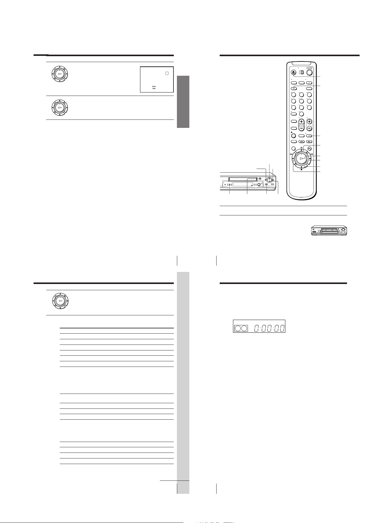
Basic Operations
Playing a tape
EJECT
]
Getting Started
COLOR
SYSTEM
m REW
A EJECT
H PLAY
X PAUSE
123
456
789
0
M FF
x STOP
CLEAR
DISPLAY
X PAUSE
H PLAY
M FF
x STOP
m REW
1 Turn on your TV and set it to the video channel.
2 Insert a tape.
The VCR turns on and starts playing
automatically if you insert a tape with its
safety tab removed.
3 Press H PLAY.
PLAY
When the tape reaches the end, it will rewind automatically.
OK
Additional tasks
To
Stop play
Pause play
Resume play after pause
Fast-forward the tape
Rewind the tape
Eject the tape
To set the colour system
If streaks appear during playback, press COLOR SYSTEM on the VCR to
conform to the system that the tape was recorded in. (Normally, the colour
system is correctly set whenever the tape is inserted.)
If your tape was
recorded in
PAL
MESECAM
NTSC
Press
x STOP
X PAUSE
X PAUSE or H PLAY
M FF during stop
m REW during stop
Z EJECT
Press COLOR SYSTEM until the indication below
appears in the display window.
PAL
PAL
NTSC
To play an NTSC-recorded tape
Set NTSC PB in the SET UP MENU according to the colour system of your
TV. For details, see page 65.
If your TV is
PAL
NTSC 4.43
NTSC 3.58
Set NTSC PB to
ON PAL TV
4.43
3.58
Getting Started
33
Basic Operations
Basic Operations
34
Playing a tape (continued)
To use the time counter
At the point on the tape that you want to find later, press CLEAR. The
counter in the display window resets to “0:00:00.” Search for the point
afterwards by referring to the counter.
SP
To display the counter on the TV screen, press DISPLAY. Press DISPLAY
again and the counter will disappear from the TV screen.
Notes
• When you play back a tape recorded in the PAL or MESECAM colour system,
streaks may appear even if the colour system setting is set to AUTO. If so, select the
colour system PAL or MESECAM in the PAL/MESECAM option of the SET UP
MENU (see page 65 for details).
• The counter resets to “0:00:00” whenever a tape is reinserted.
• The counter stops counting when it comes to a portion with no recording.
• If a tape has portions recorded in both PAL and NTSC systems, the time counter
reading will not be correct. This is due to the difference between the counting cycles
of the two colour systems.
• Depending on your TV, the following may occur while playing an NTSC-recorded
tape:
– the picture is black and white
– the picture shakes
– no picture appears on the TV screen
– black streaks appear horizontally on the TV screen
– the colour density increases or decreases.
• Tapes recorded in the LP mode of other NTSC system VCRs can be played back on
this VCR, but the picture quality cannot be guaranteed.
• While setting the menu on the TV screen, you cannot use the H PLAY, X PAUSE,
M FF, m REW or x STOP buttons. These buttons are used for menu operations.
APC
continued
Basic Operations
35
Basic Operations
36
1-8
Recording TV
programmes
INPUT SELECT
123
456
789
0
PROG +/–
DISPLAY
REC SPEED
z REC
1 Turn on your TV and set it to the video channel.
2 Insert a tape with its safety tab in place.
PROG
3 Press PROG +/– to select the programme position you want to
record.
SP
APC
continued
Basic Operations
Basic Operations
37
Recording TV programmes (continued)
REC SPEED
4 Press REC SPEED to select the tape speed (SP or LP for the PAL
5 Press z REC to start recording.
colour system, and SP or EP for the NTSC colour system).
LP (Long Play) provides recording time twice as long as SP
(Standard Play). EP (Extended Play) provides recording time three
times as long as SP. However, SP produces better picture and audio
quality.
REC
The recording indicator lights up red in the display window.
Recording indicator
To stop recording
Press x STOP.
To check the remaining tape length
Press DISPLAY. The white bar indicates the approximate length of tape
remaining.
–
S
E
Remaining tape length
::
000
22
Time counter
To watch another TV programme while recording
1 If the TV is connected to the VCR using an audio/video cable, set the
TV to TV input. If the TV is connected to the VCR using only the aerial
cable, skip this step.
LP
LP
2 Select another programme position on the TV.
To save a recording
To prevent accidental erasure, break off the safety
tab as illustrated. To record on the tape again,
cover the tab hole with adhesive tape.
Basic Operations
38
APC
APC
Safety tab
Tips
• To select a programme position, you can use the programme number buttons on the
remote commander. For two-digit numbers, press the ? (ten’s digit) button
followed by the programme number buttons.
• You can select a video source from the LINE-1 IN or LINE-2 IN jacks. Press INPUT
SELECT or PROG +/– to display “L1” or “L2” in the display window.
• The display appears on the TV screen indicating information about the tape, but the
information will not be recorded on the tape.
• If you do not want to watch TV while recording, you can turn off the TV.
• You can have the VCR stop recording automatically after starting at a specified
time. For details, see “Setting the recording duration time” on page 58.
Notes
• The display does not appear during still (pause) mode or slow-motion playback.
• It may take up to one minute for the VCR to calculate and display the remaining
tape length after you press DISPLAY.
• The remaining tape length does not appear while playing or recording in the NTSC
system.
Basic Operations
Recording TV programmes using the
Easy Timer function
The Easy Timer function allows you to make a timer recording of a
programme without turning on your TV. Set the recording timer to record
only one programme that will be broadcast within the next 24 hours using
the EASY TIMER knob. If the VCR clock has not been set, you can also set
the clock before setting the timer recording.
Setting the Easy Timer
Before you start…
• Insert a tape with its safety tab in
place. Make sure the tape is longer
than the recording time.
REC SPEED
SP/LP (SP/EP)
EASY TIMER
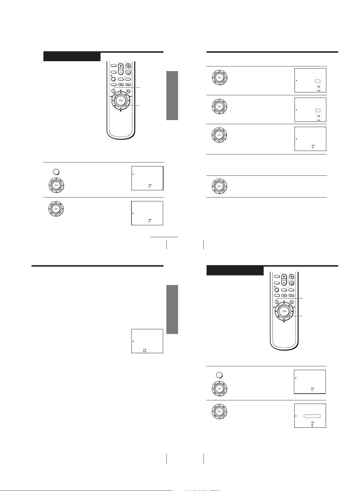
1 Push the EASY TIMER knob.
2 Set the recording start time by turning the EASY TIMER knob
3 Push the EASY TIMER knob to confirm the start time setting.
The START indicator appears in the display window.
If the clock has not been set,
“–:– –” appears. Go to step 2
in “Setting or changing the
Easy Clock” on page 42.
EASY TIMER
clockwise or counterclockwise to increase or decrease the time by 15
minutes.
To increase or decrease the
time by one minute, press
PROGRAM +/–.
EASY TIMER
The STOP indicator appears.
SP
SP
SP
PROGRAM +/–
EASY TIMER
knob
START
APC
START
APC
STOP
APC
Basic Operations
39
Basic Operations
40
1-9
EASY TIMER
SP
APC
CLOCK
START
4 Set the recording stop time in the same way as in step 2, then push
5 Turn the EASY TIMER knob clockwise or counterclockwise to select
the EASY TIMER knob.
A programme number flashes.
EASY TIMER
the programme you want to record.
To select the tape speed, press
REC SPEED.
REC SPEED
SP/LP
SP
SP
LP
APC
APC
Recording TV programmes using the Easy Timer function
(continued)
Setting or changing the
Easy Clock
When “–:– –” is displayed in the display
window, the VCR clock has not been set.
You need to set the clock using the Easy
Clock function before setting the timer.
You can also change the current time
using the Easy Clock function.
123
456
789
0
Programme
number
buttons
EASY
TIMER
PROG +/–
(SP/EP)
EASY TIMER
6 Push the EASY TIMER knob to confirm the setting.
EASY TIMER
3 Push the EASY TIMER knob to finish setting the clock.
indicator appears in
The
t
the display window and the
VCR stands by for recording.
The VCR enters the timer recording setting mode.
To continue the Easy Timer
setting, go to step 2 in
“Setting the Easy Timer” on
page 40.
To quit the Easy Timer setting mode without changing any settings,
push the EASY TIMER knob repeatedly until the
appears in the display window.
To set the timer and clock setting using the remote commander
You can also use the remote commander to set the Easy Timer and Easy
Clock. The operations on the VCR and the remote commander correspond as
follows:
To
Confirm the setting and go to
the next setting
Change the time by 15 minutes
(in START/STOP mode)
Change the time by one minute
(in START/STOP mode)
Select the programme
Change the hour/minute by
one hour/minute (in CLOCK
mode)
You can also use the programme number buttons to set the clock, start and
stop times, and the programme you want to record. Just press the
programme number buttons to enter the hours and minutes. For example:
• To set the clock to “8:20”, press 0, 8, EASY TIMER , 2, 0 and EASY TIMER
in sequence.
• To set the start or stop time to “8:20”, press 0, 8, 2, 0 and EASY TIMER in
sequence.
If you make a mistake, re-enter the correct digits before pressing
EASY TIMER .
Do this on the VCR
Push the EASY TIMER
knob
Turn the EASY TIMER
knob or hold PROGRAM
+/– down
Press PROGRAM +/–
Turn the EASY TIMER
knob or press PROGRAM
+/–
Turn the EASY TIMER
knob or press PROGRAM
+/–
SP
t
Do this on the remote
commander
Press EASY TIMER
Hold PROG +/– down
Press PROG +/–
Press PROG +/– or
INPUT SELECT
Press PROG +/–
continued
Basic Operations
START
APC
indicator
continued
Basic Operations
Basic Operations
41
Basic Operations
43
EASY TIMER
knob
EASY TIMER
1 • When “–:– –” is displayed in the display window, push the
EASY TIMER
2 Set the current time using the EASY TIMER knob.
Basic Operations
42
Recording TV programmes using the Easy Timer function
(continued)
EASY TIMER knob.
• To change the clock setting, push and hold the EASY TIMER knob
on the VCR for more than three seconds.
The CLOCK indicator and the current clock setting appear in the
display window.
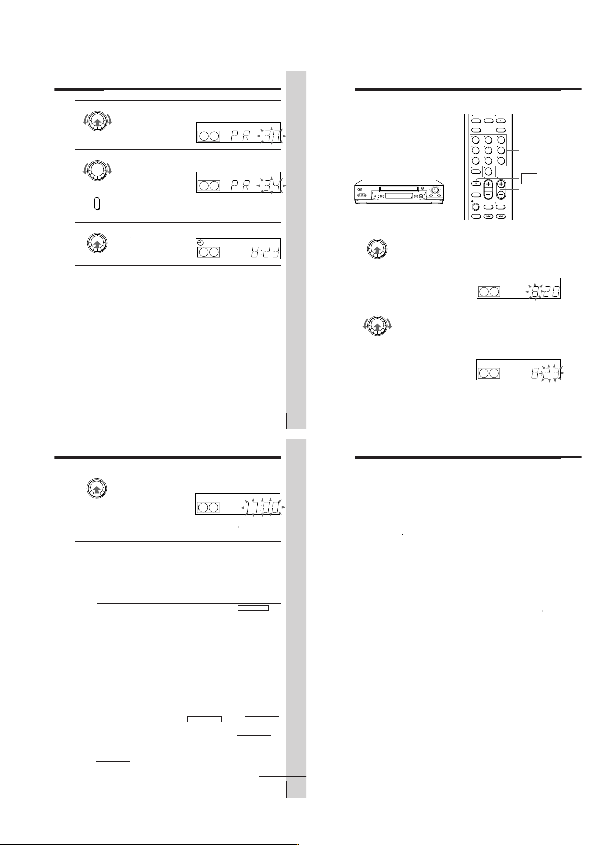
1 Turn the EASY TIMER knob clockwise or counterclockwise to
enter the current hour.
2 Push the EASY TIMER knob to confirm the hour setting.
3 Turn the EASY TIMER knob to increase or decrease the minutes
setting by a minute at a time.
SP
To stop recording
To stop the VCR while recording, press x STOP.
To check or change the timer setting
Push the EASY TIMER knob repeatedly until the setting you want to check
or change flashes. Then re-enter the new setting, if necessary. If you do not
want to change any of the settings, push the EASY TIMER knob repeatedly
indicator appears in the display window.
until the
t
You can also change the timer setting using the TIMER SET/CHECK menu.
For details, see page 59.
To cancel the timer setting
To cancel the Easy Timer setting while entering a setting, press CLEAR on
the remote commander or press PROGRAM + and – on the VCR at the same
time.
To use the VCR after setting the timer
To use the VCR before a timer recording begins, just press ?/1. The
indicator turns off and the VCR switches on. Remember to press ?/1 to reset
the VCR to the timer recording standby mode after using the VCR.
You can also do the following tasks while the VCR is recording:
• Reset the counter.
• Display tape information on the TV screen.
• Check the timer settings.
• Watch another TV programme.
To watch the recorded programme right after recording with the Easy
Timer
The SEARCH MODE indicator starts flashing when the VCR finishes the
Easy Timer recording. To watch the recorded programme, push the EASY
TIMER knob. The VCR turns on, starts searching, then automatically starts
playback from the beginning of the recording. For details, see page 51.
Basic Operations
44
CLOCK
START
APC
t
1-10
Tips
• To record from a source connected to the LINE-1 IN or LINE-2 IN jacks, press
INPUT SELECT or PROG +/– or turn the EASY TIMER knob to display “L1” or
“L2” in the display window.
• To record NTSC signals, set the tape speed to SP or EP. To record in the EP mode,
set the tape speed to “LP” in the display window.
Notes
• You cannot set the Easy Timer if eight programmes have already been set.
• You can set the timer for only one programme using the Easy Timer function. If you
want to set the timer for other programmes, use the G-CODE system or the TIMER
SET/CHECK menu. For details, see pages 46 and 49.
• You cannot set the date using the Easy Timer function. Set the date using the
CLOCK SET menu if you want to set the timer with the G-CODE system or the
TIMER SET/CHECK menu. For details, see page 32.
indicator flashes in the display window when you complete the setting with
• The
t
no tape inserted.
Basic Operations
Recording TV
programmes
using the G-CODE
system
Just enter the G-CODE number, listed in
the TV programme guide, for the
programme you want to record. The
date, times and programme position of
that programme are set automatically.
You can preset up to eight programmes
at a time.
Before you start…
• Check that the VCR clock is set to the
correct time.
• Insert a tape with its safety tab in
place. Make sure the tape is longer
than the total recording time.
• Turn on your TV and set it to the
video channel.
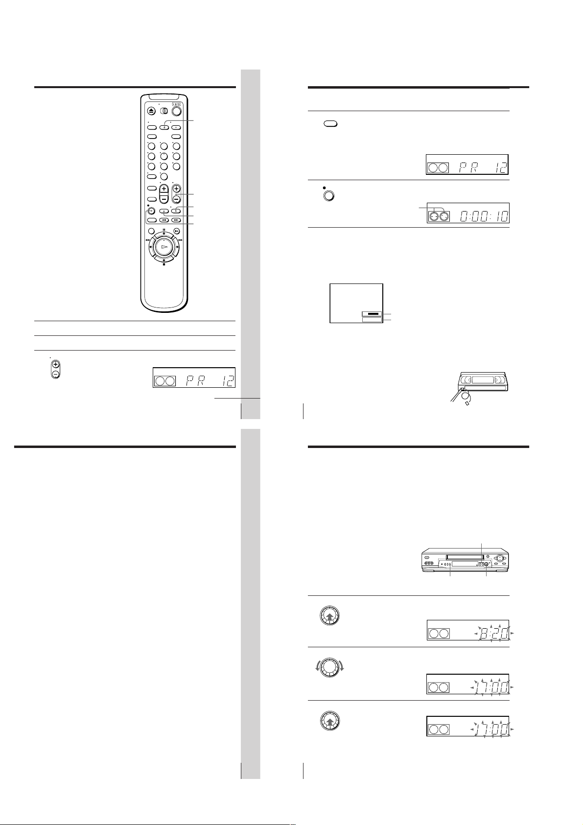
G-CODE
1 Press G-CODE.
123
456
789
0
?/1
CLEAR
G-CODE
Programme
number
buttons
REC SPEED
OK
</,
G–CODE
G–CODE NO. SP / LP
[ –––––––– – ]
SET
:[ 0 – 9 ]
SP / LP
:[ REC SPEED ]
[ SP ]
2 Press the programme number buttons to
123
enter the G-CODE number for the
456
programme you want to record.
789
If you make a mistake, press CLEAR and
0
re-enter the correct number.
REC SPEED
3 Press REC SPEED to select SP or LP.
4 Select ONCE, DAILY or WEEKLY by using
</,, then press OK:
PLAY
OK
To record
Only once
Everyday Monday to Friday
Once a week
The date, start and stop times, programme position, and tape speed
appear on the TV screen.
Select
ONCE
DAILY
WEEKLY
If the information is not correct, press CLEAR to cancel the setting.
5 To enter another setting, repeat steps 1 to 4.
• ]/1
6 Press ?/1 to turn off the VCR.
The t indicator appears in the display window and the VCR
stands by for recording.
Basic Operations
G–CODE
G–CODE NO. SP / LP
[ 82477691– ]
• ONCE DAILY WEEKLY
[
:
SELECT
CONFIRM :[ OK ]
CANCEL
:[ CLEAR ]
G–CODE
G–CODE NO. SP / LP
• ONCE DAILY WEEKLY
[
:
]
SELECT
CONFIRM
[ OK ]
:
CANCEL
:[ CLEAR ]
G–CODE
G–CODE NO. SP / LP
[ 82477691– ]
RECORDING TIME
DATE START STOP
12
TUE 19 : 00
25 .
:[ CLEAR ]
CANCEL
45
Basic Operations
46
Recording TV programmes using the G-CODE system (continued)
[ SP ]
]
To record satellite broadcasts
If you connect the satellite tuner and the VCR, you can record satellite
programmes using the G-CODE number when available.
1 Turn on the satellite tuner.
2 On the satellite tuner, select the satellite programme for which you wish
to make a timer setting.
3 Repeat the steps described on pages 46 and 47.
[ LP ][ 82477691– ]
[ LP ]
20 : 00
PROG
6
LP
Basic Operations
4 Keep the satellite tuner turned on until the VCR finishes recording the
satellite programme for which you have made a timer setting.
Tips
• To cancel the procedure, press G-CODE before you press OK.
• To record NTSC signals, set the tape speed to SP or EP. To record in the EP mode, set
the tape speed to “LP”.
Notes
• The G-CODE system used in this VCR is for Singapore, Malaysia, Hong Kong,
Macau, etc. and cannot be used in areas such as U.S.A., Canada, Japan, Korea,
Taiwan, and U.K.
• The t indicator flashes in the display window when you press ?/1 with no tape
inserted.
To stop recording
To stop the VCR while recording, press x STOP.
continued
Basic Operations
47
1-11
Basic Operations
48
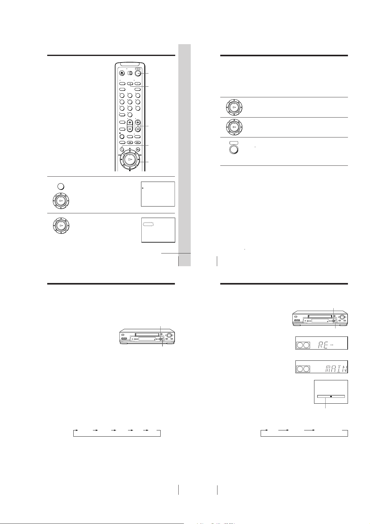
Setting the timer
SP
APC
START
SP
APC
START
RE- MAIN
0:15 (remaining
time of the tape)
TAPE POSITION
– – – – – – – – – – – – – – – –
manually
You can preset up to eight programmes
at a time.
Before you start…
• Check that the VCR clock is set to the
correct time.
• Insert a tape with its safety tab in
place. Make sure the tape is longer
than the total recording time.
• Turn on your TV and set it to the
video channel.
123
456
789
0
?/1
INPUT SELECT
PROG +/–
Setting the timer manually (continued)
To record the same programme every day or the same day every
week, press m while the date is flashing. For details, see “Daily/
weekly recording” below.
To record from a source connected to the LINE-1 IN or LINE-2 IN
jacks; press INPUT SELECT or PROG +/– to display “L1” or “L2” in
the “PROG” position.
3 Press , to confirm the setting.
PLAY
The cursor (B) appears at the beginning of the line. To enter another
OK
setting, move the cursor to the next line and repeat step 2.
4 Press OK.
PLAY
OK
MENU
1 Press MENU and select TIMER SET/
2 Set the date, start and stop times,
Search Operations
CHECK, then press OK.
PLAY
OK
programme position, and tape speed:
PLAY
OK
1 Press , to select each item in turn.
2 Press M/m to set each item.
To correct a setting, press < to return to
that setting and reset it.
TIMER SET / CHECK TUE
TIMER SET / CHECK TUE
Searching for the
beginning of an
Easy Timer
recorded
programme
If you record a programme using the
Easy Timer function, you can easily find
the beginning of the recording with the
SEARCH MODE function. The SEARCH
MODE indicator flashes when the VCR
finishes making an Easy Timer
recording.
Push the EASY TIMER knob.
The VCR turns on, rewinds to the beginning of the recorded programme and
starts playback automatically. The SEARCH MODE indicator turns off.
Tip
• You can start the SEARCH MODE function after the flashing of the SEARCH
MODE indicator has been stopped. The flashing stops when you turn on the VCR
and press the SEARCH MODE button (Do not press any button at this point,
otherwise this SEARCH MODE function will be cancelled). To start the SEARCH
MODE function, press the SEARCH MODE button repeatedly until the SEARCH
MODE indicator flashes. Push the EASY TIMER knob. The VCR rewinds and starts
playback automatically.
If you continue to press the SEARCH MODE button while the SEARCH MODE
indicator is flashing, you can enter other search operations (For details, see the
following pages). Each press of the SEARCH MODE button changes the search
operations as follows:
REMAIN BLANK INDEX TIME Off
MENU
OK
M/m/</,
START STOP PROG
12
TUE
– : –– –: –– ––
Basic Operations
EASY TIMER
knob
SEARCH MODE
25 .1
25. 1
continued
DATE
– .–– –: –– – :–– –– –
– .–– –: –– – :–– –– –
– .–– –: –– – :–– –– –
– .–– –: –– – :–– –– –
– .–– –: –– – :–– –– –
– .–– –: –– – :–– –– –
– .–– –: –– – :–– –– –
– .–– –: –– – :–– –– –
DATE START STOP PROG
2.5
– .–– –: –– – :–– –– –
– .–– –: –– – :–– –– –
– .–– –: –– – :–– –– –
– .–– –: –– – :–– –– –
– .–– –: –– – :–– –– –
– .–– –: –– – :–– –– –
– .–– –: –– – :–– –– –
2
2
SP
Basic Operations
49
5 Press ?/1 to turn off the VCR.
• ]/1
The
indicator appears in the display window and the VCR
t
stands by for recording.
To record from other equipment, leave the connected equipment
switched on.
To stop recording
To stop the VCR while recording, press x STOP.
Daily/weekly recording
In step 2 above, press m to select the recording pattern. Each time you press
m, the indication changes as shown below. Press M to change the indication
in reverse order.
the current date t SUN-SAT (Sunday to Saturday) t MON-SAT (Monday
to Saturday) t MON-FRI (Monday to Friday) t EVERY SAT ..... t EVERY
MON t EVERY SUN t 1 month later t (dates count down) t the
current date
Tips
• To set the programme position, you can also use the PROG +/– or programme
number buttons.
• To set the tape speed, you can also use the REC SPEED button.
• To record NTSC signals, set the tape speed to SP or EP. To record in the EP mode, set
the tape speed to “LP”.
Note
indicator flashes in the display window when you press ?/1 with no tape
• The
t
inserted.
Basic Operations
50
Searching for the
current position
on a tape
This feature enables you to find the
current position on a tape as well as the
remaining time of the tape.
1 Press SEARCH MODE repeatedly until the
REMAIN indicator appears in the display
window as shown on the right.
The SEARCH MODE indicator lights up.
2 Push the EASY TIMER knob to display
the tape meter on the TV screen.
The SEARCH MODE indicator turns off.
A cursor (x) indicates the current position
on the tape.
“REMAIN” and the remaining time of the tape appear in the display window in
the following order:
EASY TIMER
SEARCH MODE
n
Tape meter
knob
Note
• This SEARCH MODE function will be cancelled (the SEARCH MODE indicator
turns off) if:
– The VCR starts recording other programmes.
– You press the H PLAY, M FF, m REW or A EJECT button while the VCR is
on.
Search Operations
To stop the Search function
Press x STOP.
Notes
• To display the remaining time correctly, you may have to select the TAPE LENGTH in the SET
UP MENU according to the type of the tape that you are using. For details, see page 65.
• In step 2, the VCR automatically rewinds and fast-forwards the tape only if you press the
SEARCH MODE button right after you insert a tape. This is so that the VCR can measure the
current position on the tape.
51
• You cannot use this function during any recording mode.
52 Search Operations
1-12

Searching using
the Blank Search
function
This feature enables you to find a blank
section on your tape.
1 Press SEARCH MODE repeatedly until the
BLANK indicator appears in the display
window.
The SEARCH MODE indicator lights up.
2 Push the EASY TIMER knob on the VCR.
The SEARCH MODE indicator turns off.
The VCR fast-forwards to the end of the
tape. Then, the VCR rewinds the tape to
the last recorded programme. After a few
seconds, the VCR starts playback and
stops at the beginning of the blank
section.
“BLANK” and the remaining time of the
blank section appear alternately in the
display window for about one minute.
To stop searching
To stop the VCR while searching for a blank section, press x STOP.
Notes
• To display the remaining time correctly, you may have to select the TAPE LENGTH in the SET
UP MENU according to the type of the tape that you are using. For details, see page 65.
• In step 2, “FULL” will appear in the display window for about one minute, if:
– there is no blank section available on the tape.
– the remaining time of a blank section is less than one minute.
• The VCR can only detect the blank section between the end of the tape and the end of the last
recorded programme.
Blank section
SP
SP
EASY TIMER
knob
SEARCH MODE
START
APC
START
APC
n
APC
Searching using
the index
function
The VCR marks the tape with an index
signal at the point where each recording
begins. Use these signals as references to
find a specific recording. The VCR can
search up to 99 index signals ahead of or
behind the current position. You can
either use the INDEX SEARCH buttons
on the remote commander or the
SEARCH MODE button and EASY
TIMER knob on the VCR.
Using the INDEX SEARCH
buttons on the remote
commander
1 Insert an indexed tape into the VCR.
2 Press ./> INDEX SEARCH repeatedly to specify how many
index signals ahead or behind you want to search:
• To search ahead, press > INDEX SEARCH.
• To search backwards, press . INDEX
SEARCH.
The VCR starts searching and the index
number on the TV screen counts down to
zero. Playback starts from the point about
five seconds ahead of the specified index
mark.
INDEX
SEARCH
./>
INDEX
SEARCH
8
Last recorded
programme
Using the SEARCH MODE
button and EASY TIMER
knob on the VCR
1 Press SEARCH MODE on the VCR repeatedly until “INDEX” appears
in the display window (the SEARCH MODE indicator lights up).
2 Turn the EASY TIMER knob to specify how many index signals ahead
or behind you want to search:
• To search ahead, turn the EASY TIMER knob clockwise.
• To search backwards, turn the EASY TIMER knob counterclockwise.
End of tape
SP
SP
3 Push the EASY TIMER knob.
The VCR starts searching. Playback starts (the SEARCH MODE
indicator turns off) from the point about five seconds ahead of the
specified index mark.
To stop searching
Press x STOP.
Note
• No index signal will be added when recording starts from recording pause.
However, an index signal will be marked if you change the channel during
recording pause.
Search Operations
EASY TIMER
knob
SEARCH MODE
APC
START
APC
Search Operations
53
54 Search Operations
Searching using
the Time Search
function
You can easily find a specific point on a
tape by using the Time Search function.
For example, you can find a recorded
section 15 minutes ahead of or behind
the current position of a tape by using
the Time Search function.
1 Press SEARCH MODE repeatedly until “TIME” appears in the display
window (the SEARCH MODE indicator lights up).
2 Turn the EASY TIMER knob clockwise or counterclockwise to set the
length of time you want the VCR to fast-forward or rewind the tape.
Each turn on the knob increases or decreases the duration by 15
minutes.
For example, if you want to watch a recorded section 15 minutes ahead
of the current position, turn the EASY TIMER knob once clockwise.
To change the time by one
minute, press PROGRAM
+/–.
3 Push the EASY TIMER knob.
The VCR starts searching and the tape counter starts counting until it
reaches the specified point.
The VCR starts playback automatically when the tape counter reaches
the specified point (the SEARCH MODE indicator turns off).
To stop searching
Press x STOP.
Tip
• The VCR can search up to three hours ahead of or behind the current position of a
tape.
55
56 Search Operations
SP
SP
SP
EASY TIMER
knob
SEARCH MODE
APC
APC
APC
1-13
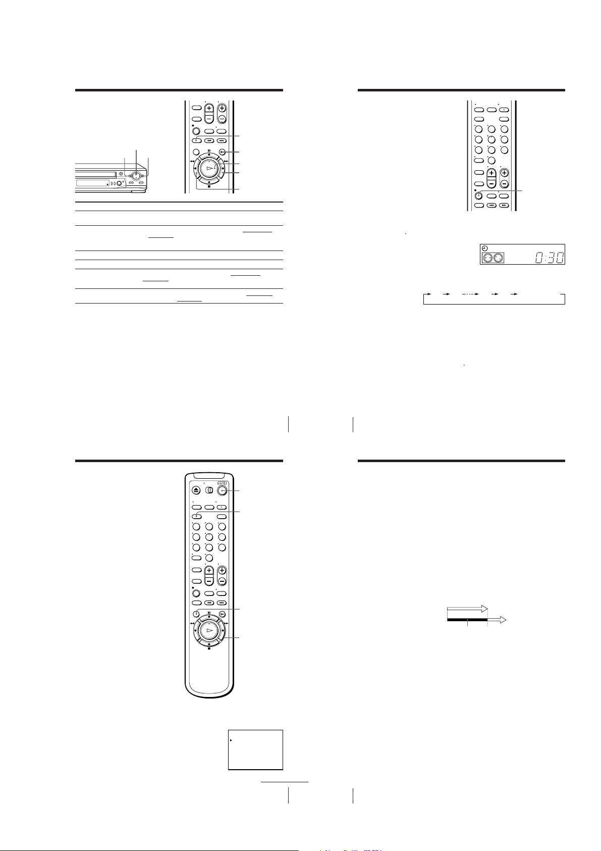
Additional Operations
0:30 1:00 6:005:30 Normal recording
Playing/searching
at various speeds
H PLAY
m REW M FF
Playback options
View the picture during fastforward or rewind
Play at high speed
Play at twice the normal speed
Play in slow motion
Play frame by frame
Rewind and start play
To resume normal playback
Press H PLAY.
Tips
• Adjust the picture using TRACKING +/– on the VCR if:
– streaks appear while playing in slow motion.
– the picture shakes during pause.
To set tracking to the centre position, press both buttons (+/–) at the same time.
• If noise appears during pause or frame-by-frame playback, first switch to the slow
motion playback, then adjust the picture using TRACKING +/– on the VCR.
Notes
• The playback sound is muted during these operations.
• In LP or EP mode, noise may appear or there may be no colour.
• The picture may show noise when playing at high speed in reverse.
• On-screen symbols may shake while playing or searching at various speeds.
Operation
During fast-forward, hold down M FF. During rewind, hold
down m REW.
• During playback, press M FF or m REW
commander.
• During playback, hold down M FF or m REW. When you
release the button, normal playback resumes.
During playback or pause, press ×2.
During playback or pause, press y SLOW.
During pause, press M FF or m REW
commander. Hold down the button to play one frame each
second.
While the tape is stopped, hold down 0 REW
press H PLAY
on the VCR.
×2
y SLOW
H PLAY
M FF
m REW
on the remote
on the remote
on the VCR and
Additional Operations
Setting the
recording
duration time
After you have started recording in the
normal way, you can have the VCR stop
recording automatically after a specified
duration.
1 While recording, press z REC.
indicator appears in the display window.
The
t
2 Press z REC repeatedly to set the duration.
Each press advances the time in increments of 30 minutes.
The tape counter decreases minute by minute to 0:00, then the VCR
stops recording and turns off automatically.
To extend the duration
Press z REC repeatedly to set to the new duration.
To cancel the duration
Press z REC repeatedly until the
to normal recording mode.
To stop recording
To stop the VCR while recording, press x STOP.
57
58 Additional Operations
123
456
789
0
z REC
SP
indicator turns off and the VCR returns
t
APC
Checking/
changing/
cancelling timer
settings
Before you start…
• Turn on your TV and set it to the
video channel.
1 Press ?/1 to turn on the VCR.
2 Press MENU, then select TIMER SET/CHECK and press OK:
• If you want to change or cancel a setting,
go on to the next step.
• If you do not need to change or cancel the
settings, press OK, then turn off the VCR
to return to recording standby.
123
456
789
0
?/1
CLEAR
MENU
OK
M/m/</,
TIMER SET / CHECK TUE
DATE START STOP PROG
MO
EVERY
– .–– –: –– – :–– –– –
– .–– –: –– – :–– –– –
– .–– –: –– – :–– –– –
– .–– –: –– – :–– –– –
25. 1
SUN
.6 1 7:00 8:00 6
2
.8 1 1 :00 0:00 50
TUE
N– 0:12 3:00 227
SAT
1
SUN
3:00 0:00
2
continued
Additional Operations
Checking/changing/cancelling timer settings (continued)
3 Press M/m to select the setting you want to change or cancel:
• To change the setting, press </, to select the item you want to
change, and press M/m to reset it. Then, press , repeatedly until the
cursor (B) appears at the beginning of the line.
• To cancel the setting, press CLEAR.
4 Press OK.
If any timer settings remain, turn off the VCR to return to recording
standby.
When the timer settings overlap
The programme that starts first has priority and the second programme
starts recording only after the first programme has finished. If the
programmes start at the same time, the programme listed first in the menu
has priority.
Programme 1
Programme 2
Will be cut off
2
SP
LP
LP
SP
L
59
60 Additional Operations
1-14
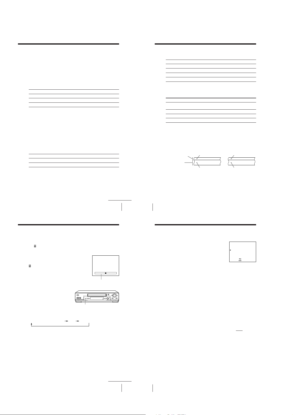
Recording stereo and bilingual
programmes
In the ZWEITON (German stereo) system
This VCR automatically receives and records stereo and bilingual
programmes based on the ZWEITON system. When a stereo or bilingual
programme is received, the STEREO indicator appears in the display
window.
To select bilingual sound while recording
Press AUDIO MONITOR to select the sound you want.
To listen to
Main
Sub
Main and sub
On-screen display
MAIN
SUB
MAIN/SUB
In the NICAM system
This VCR receives and records stereo and bilingual programmes based on
the NICAM system (the NICAM indicator appears). When a stereo or
bilingual programme is received, the STEREO indicator appears in the
display window.
To record a NICAM programme, HIFI AUDIO in the SET UP MENU should
be set to NICAM (initial setting). To check the menu setting, see page 65.
To select the sound while recording
Press AUDIO MONITOR to select the sound you want.
Stereo programme
To listen to
Stereo
Standard sound*
* Usually the mixed sound of left and right channels (monaural)
On-screen display
STEREO
No indicator
Display window
STEREO
STEREO
STEREO
Display window
STEREO
No indicator
continued
Additional Operations
Recording stereo and bilingual programmes (continued)
Bilingual programme
To listen to
Main
Sub
Main and sub
Standard sound*
* Usually the main sound (monaural)
On-screen display
MAIN
SUB
MAIN/SUB
No indicator
Display window
STEREO
STEREO
STEREO
No indicator
Selecting the sound during playback
Press AUDIO MONITOR to select the sound you want.
To listen to
Stereo/main and sub
(left and right channels)
Left channel/main
Right channel/sub
Standard sound*
* The mixed sound of left and right channels (monaural)
On-screen display
STEREO
L CH
R CH
No indicator
Display window
STEREO
STEREO
STEREO
No indicator
How sound is recorded on a video tape
The VCR records sounds onto two separate tracks. Hi-fi audio is recorded
onto the main track along with the picture. Monaural sound is recorded onto
the normal audio track along the edge of the tape.
Normal audio track
(monaural)
Hi-fi audio track
(main track)
Notes
• To play a tape in stereo, you must use the AUDIO OUT connections.
• When you play a tape recorded in monaural, the sound is heard in monaural
regardless of the AUDIO MONITOR setting.
• If the AUDIO MONITOR button does not function, check that AUDIO MIX in the
SET UP MENU is set to OFF.
• If HIFI AUDIO is set to STD, the standard sound will be recorded on both the hi-fi
and normal audio tracks. Pressing AUDIO MONITOR will not change the sound.
61
62 Additional Operations
Stereo Bilingual
Usually mixed left/
right channels
Stereo sound (left/
right channels)
Usually main
sound
Main (left channel)
Sub (right channel)
Adjusting the picture
Adjusting the tracking
Although the VCR automatically adjusts the tracking when playing a tape
indicator flashes in the display window, then turns off), distortion
(the
may occur if the tape was recorded in poor condition. If so, manually adjust
the tracking.
Press the TRACKING +/– buttons on the VCR to
display the tracking meter. The distortion should
disappear as you press one of the two buttons (the
indicator lights up). To resume automatic
tracking adjustment, eject the tape and reinsert it.
About the R2 (Reality Regenerator) function
The R2 function automatically
adjusts the picture to the most
suitable quality during playback.
When playback starts, the R
function activates and the R
button lights up.
Each press of the button changes the effect and indication in the display
window as follows:
2
2
SOFTREAL (status of playback started) DYNA (dynamic)
2
R
NORMAL TRACKING
– – – – – – – – – – – – – – – – –
Tracking meter
Adjusting the picture (continued)
About the Adaptive Picture Control (APC) function
The Adaptive Picture Control (APC) function
automatically improves recording and playback
quality by adjusting the VCR to the condition of
the video heads and tape. To maintain better
picture quality, we recommend that you set APC to
ON in the SET UP MENU (The APC indicator
lights up in the display window).
APC playback
The APC function automatically works on all types of tapes, including rental
tapes and tapes that were not recorded with APC.
APC recording
Whenever you insert a tape and first start recording, the VCR adjusts to the
tape using the APC function (the APC indicator flashes rapidly). This
adjustment is retained until the tape is ejected.
To deactivate the APC function
Press MENU and select SET UP MENU, then set APC to OFF. The APC
indicator in the display window turns off.
Tip
• To set the tracking to the centre position, press the TRACKING + and – buttons at
the same time.
Note
• There is a delay of a few seconds before the VCR actually starts recording while the
VCR analyses the tape. To avoid the delay, first set the VCR to recording pause (the
APC indicator flashes slowly) and press z REC to have the VCR analyse the tape
(the APC indicator flashes rapidly). After the APC indicator stops flashing, press
X PAUSE to start recording immediately. If you press X PAUSE before the APC
indicator stops flashing, the APC function is cancelled.
SET UP MENU 1/2
AUDIO MIX
HIFI AUDIO
APC
PAL / MESECAM
NTSC PB
•
ON PAL TV 4. 43 3. 58
SELECT
SET
OFF
•ON
NICAM
•STD
OFF
ON
•
•
PAL
MESECAM
AUTO
[]
:
[
:
]
continued
Additional Operations
63
1-15
64 Additional Operations
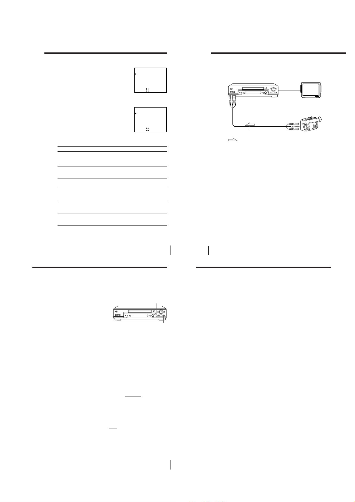
Changing menu options
1 Press MENU, then select SET UP MENU.
2 Press M/m to select the option to change, then
press </, to change the setting.
The SET UP MENU has 2 pages. To select
page 2, press m repeatedly until page 2
appears. To select page 1 press M repeatedly
until page 1 appears.
3 Press OK to return to the original screen.
Menu choices
Initial settings are indicated in bold print.
Menu option
AUDIO MIX
HIFI AUDIO
APC
PAL/MESECAM
NTSC PB
TAPE LENGTH
Set this option to
ON to listen to the hi-fi and normal audio tracks at the same
time. The AUDIO MONITOR button will not function.
OFF to listen to hi-fi and normal audio tracks separately. Select
the sound using the AUDIO MONITOR button.
STD to record standard sound on the hi-fi audio track.
NICAM to record NICAM broadcasts on the hi-fi audio track.
For details, see page 61.
ON to switch on the APC (Adaptive Picture Control) function
and improve picture quality. OFF to switch off APC.
AUTO to have the VCR automatically select the colour system
for recording and playback. If the picture has no colour or
unusual colours, set to PAL or MESECAM according to your
local colour system.
ON PAL TV to play back an NTSC-recorded tape on a PAL TV.
4.43 or 3.58 according to the colour system of your NTSC TV.
For details, see page 35.
AUTO to have the VCR automatically select the tape length.
For E240, E260 or E300 tapes, set it according to the tape type
that you are using to display the remaining time correctly.
Note
• You may not be able to display the remaining time correctly for an NTSC
tape using the TAPE LENGTH menu.
SET UP MENU 1/2
AUDIO MIX
HIFI AUDIO
APC
PAL / MESECAM
NTSC PB
•
ON PAL TV 4 . 43 3 . 58
SELECT
SET
SET UP MENU 2/2
TAPE LENGTH
•
AUTO
SELECT
SET
Additional Operations
ON
•
•
PAL
AUTO
[]
:
[
:
]
E240 E260 E300
[]
:
[
:
]
OFF
•ON
NICAM
•STD
OFF
MESECAM
Connecting to a VCR or stereo system
How to connect to record on this VCR
This VCR (Recorder)
LINE-2 IN
LINE OUT
VMC-810HG audio/video cable (not supplied)
: Signal flow
How to connect to a stereo system
Connect LINE-2 IN AUDIO on this VCR to the audio output jacks on the
stereo system, using the RK-C510HG audio cable (not supplied).
Tips
• If the other VCR is a monaural type and connected to this VCR’s LINE-2 IN jacks,
connect the audio plug to the AUDIO L (white) jack. The sound is recorded on both
right and left channels. When connecting to the AUDIO R (red) jack, the sound is
recorded only on the right channel.
• You can also use the LINE-1 IN jacks instead. If the other VCR is a monaural type,
the sound is recorded only on the channel whose jack is connected to the audio
plug. To record on both right and left channels, connect the audio plugs to the
AUDIO R/L jacks using a VMC-910HG audio/video cable (not supplied).
Notes
• Make sure you connect the plugs to the jacks of the same colour.
• If you connect this VCR to both the LINE IN and LINE OUT jacks of the other VCR,
select the input correctly to prevent a humming noise.
65
66 Additional Operations
TV
Other VCR (Player)
Operation
(when recording on this VCR)
Before you start editing
• Turn on your TV and set it to the
video channel.
• Press INPUT SELECT or PROG +/–
to display “L1” or “L2” in the display
window.
• Press REC SPEED to select the tape
speed (SP or LP for the PAL system,
and SP or EP for the NTSC system).
1 Insert a source tape with its safety tab removed into the other
(playback) VCR. Search for the point to start playback and set it to
playback pause.
2 Insert a tape with its safety tab in place into this (recording) VCR.
Search for the point to start recording and press X PAUSE.
3 Press z REC on this VCR and set it to recording pause.
4 To start editing, press the X PAUSE buttons on both VCRs at the same
time.
To stop editing
Press the x STOP buttons on both VCRs.
Tips
• To edit more precisely, press the X PAUSE buttons on the VCRs to release pause.
• To cut out unwanted scenes while editing, press X PAUSE on this VCR when an
unwanted scene begins. When it ends, press X PAUSE again to resume recording.
Note
• If you start recording following the procedure above, the VCR will not start
recording with the APC function. To record a tape with the APC function, press
z REC again during recording pause in step 3 so that the VCR analyses the tape.
Then when you start recording in step 4, press X PAUSE after the APC indicator
stops flashing. If you press X PAUSE before the APC indicator stops flashing, the
APC function is cancelled.
X PAUSE
z REC
Sapphire tape cleaner
The unit incorporates a sapphire tape cleaner which cleans a video tape when it is
loaded. This cleaner can prevent the video heads from contamination by removing
dust or mold from a tape with its sapphire edge.
Head Condition Sensor
The Head Condition Sensor checks the condition of the video heads. If the heads are
dirty, a message will instruct you to insert a video head cleaning cassette.
The VCR may temporarily switch to a different head and resume playback. To switch
the heads, press H PLAY while the “PUSH [PLAY] TO RESUME TEMPORARILY”
message appears on the screen. Although playback will resume, the sound will be
monaural. You may have to manually adjust the tracking to get a better picture (see
“Adjusting the picture” on page 63). When playback is finished, be sure to clean the
heads with a video head cleaning cassette.
Be sure to use the Sony T-25CLD, T-25CLW or E-25CLDR video head cleaning
cassette. If these cleaning cassettes are not available in your area, have the heads
cleaned at your nearest Sony service facility (a standard service charge will be
required).
Additional Operations
67
Additional Information
71
1-16

Index to parts and controls
STEREO
NICAM
SP
EP
LP
STOP
APC
STARTCLOCK NTSC
PAL
Refer to the pages indicated in parentheses ( ) for details.
Front panel
Index to parts and controls (continued)
Display window
1
!•
!§
!¶
1 ?/1 ON/STANDBY switch (8)
2 Tape compartment
3 A EJECT button (35)
4 m REW (rewind) button (35, 57)
5 H PLAY button (35)
6 M FF (fast-forward) button
(35, 57)
7 z REC (record) button (38)
8 x STOP button (35)
9 X PAUSE button (35)
0 SEARCH MODE button/indicator
(51, 52, 53, 55, 56)
2
!¡!™!£
qa EASY TIMER knob (40, 51, 52, 53,
55, 56)
qs PROGRAM/TRACKING +/–
buttons (8, 63)
qd Remote sensor (5)
qf REC SPEED SP (Standard Play)/LP
(Long Play)/EP (Extended Play)
button (38)
qg COLOR SYSTEM button (35)
qh ONE TOUCH TUNING/RF (Radio
Frequency) CHANNEL button (8,
10)
2
(Reality Regenerator) button (63)
qj R
qk LINE-2 IN VIDEO/AUDIO L/R
jacks (66)
4
3
5
9
8!¢!∞ !º
7
Additional Information
6
continued
1 Timer indicator (41)
2 NICAM indicator (61)
3 STEREO indicator (61)
4 Tape speed indicator (38)
5 CLOCK indicator (42)
6 START indicator (40)
7 STOP indicator (40)
8 APC (Adaptive Picture Control)
indicator (64)
9 Tracking indicator (63)
0 Colour system indicator (35)
qa Time counter/clock/line/
programme/TV system indicator
(8, 36, 37, 42, 67)
qs Tape/recording indicator (38)
Rear panel
213
45
1 Mains lead (6)
2 LINE-1 IN AUDIO R/L/VIDEO
jacks (66)
3 AERIAL IN connector (6)
73
74
Additional Information
4 AERIAL OUT connector (6)
5 LINE OUT AUDIO R/L/VIDEO
jacks (7)
Remote commander
123
456
789
0
TV/VIDEO
1
2 Z EJECT button (35)
3 TV/VIDEO button (for TV) (5)
4 INPUT SELECT button (39, 50)
5 CLEAR button (36, 47, 60)
6 EASY TIMER button (43)
7 R
8 z REC button (38, 58)
9 REC SPEED button (38)
0 ×2 button (57)
qa MENU button (11, 65)
qs Tape/menu operation buttons
qd ?/1 (on/standby) switch (47)
qf AUDIO MONITOR button (61)
qg G-CODE button (46)
qh Programme number /? (ten’s digit)
qj PROG (programme) +/– buttons (37)
qk VOL (volume) +/– buttons (for TV)
ql DISPLAY button (38)
w; ./> INDEX SEARCH buttons (54)
wa y SLOW button (57)
remote control switch (5)
2
(Reality Regenerator) button (63)
X PAUSE/M button (35)
x STOP/m button (35)
m REW (rewind)/< button (35, 57)
M FF (fast-forward)/, button (35, 57)
H PLAY/OK button (35)
buttons (39, 43, 47)
Additional Information
75
1-17E
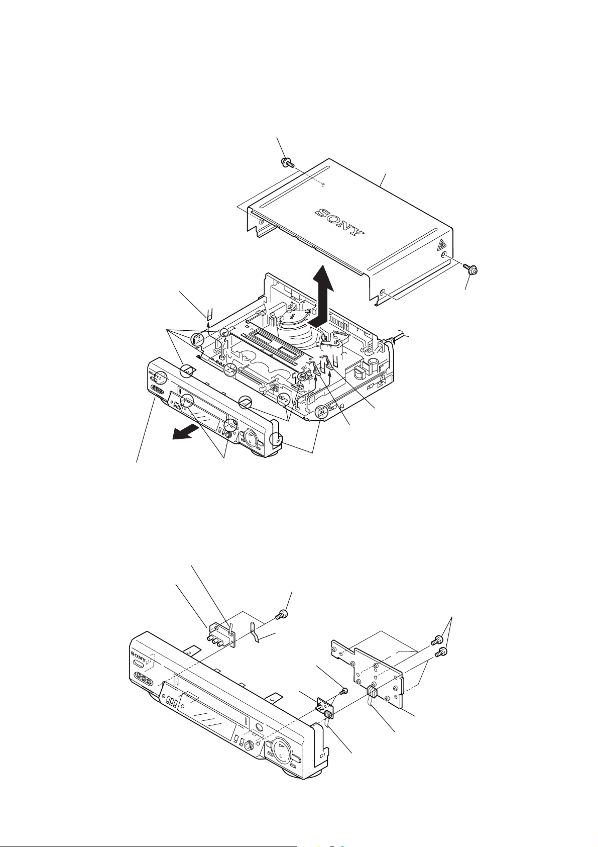
SLV-ED115/ED215/ED313/ED515/ED616/ED815/ED817/ED818/ED915/ED919/EZ111/
EZ212/EZ414/EZ715/EZ717
SECTION 2
DISASSEMBLY
NOTE: Follow the disassembly procedure in the numerical order given.
2-1. CASE, FRONT PANEL BLOCK ASSEMBLY
1 Two tapping screws
3
Upper case
4
Flat Cable FDI-002
2
Two tapping screws
Hooks
Hooks
Front panel
7
(Engaged by the six hooks)
Hooks
Hooks
2-2. DM-98 BOARD, DI-81 BOARD, FJ-31 BOARD
7 Flat Cable FDI-002
6 FJ-31 board
Two screws
8
(B2.6 × 8)
9 Earth Plate
Flat Cable FDM-010
5
6
Flat Cable FDI-002
1 Five screws
(B2.6 × 8)
Two screws
0
(B2.6 × 8)
4 DI-81 board
2 DM-98 board
3 Flat Cable FDM-010
5 Flat Cable FDI-002
2-1
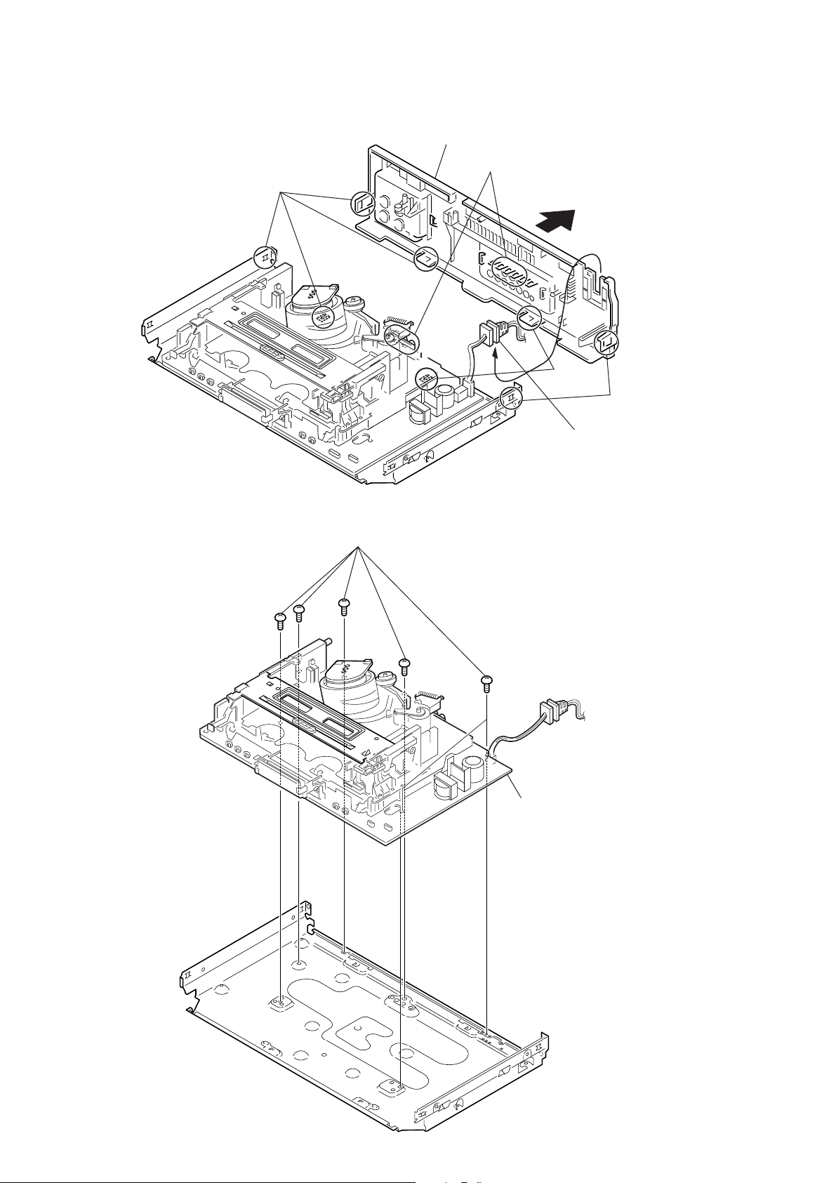
2-3. REAR PANEL
2-4. MA-402 BOARD
2 Rear panel
(Engaged by the seven hooks)
Hooks
Hooks
Hooks
Hooks
1 POWER code stopper
1 Six screws
(Sumitite (B3) +BV)
2-2
2 MA-402 board with
mechanism deck
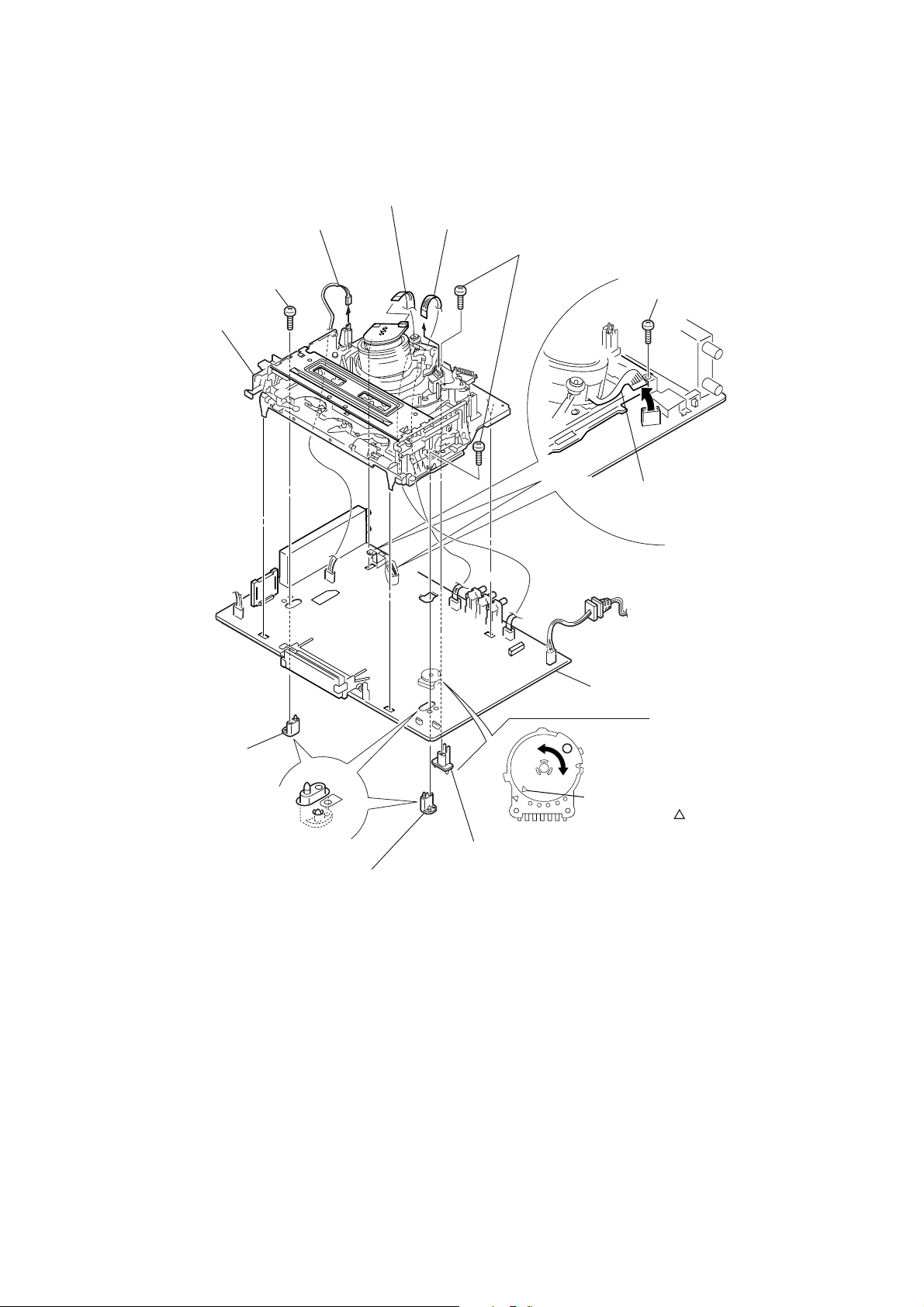
2-5. MECHANISM DECK
5 Harness FE-127
9 Screw
(BVTP 3 × 12)
qs Mechanism deck
4 Flat cable FMD-022/FMD-023
3 Flat Cable FAC-009
6 Two screws
(BVTP 3 × 12)
2 Screw
(Sumitite (B3), +BV)
1 Flexible cable
0 MD base (R)
CN202
8 MD base (R)
CN331
qa MA-402 board
Note: When mounting the mechanism deck,
first align mark on the rotary switch.
7 MD base (M)
2-3
 Loading...