

Sony SLV-EX50, SLV-EX80S, SLV-EX90S Service manual
SLV-EX50/EX80S/EX90S
RMT-V312/V312A
SERVICE MANUAL
123
456
789
0
g
VIDEO
SLV-EX90S
Refer to the SERVICE MANUAL of VHS MECHANICAL
ADJUSTMENTS VI for MECHANICAL ADJUSTMENTS.
(9-921-647-11)
Argentina Model
SLV-EX50AR/EX80SAR/
EX90SAR
Brazil Model
SLV-EX50BR/EX80SBR/
EX90SBR
S MECHANISM
* The abbreviations of EX50/EX80S and EX90S contained in this
service manual are indicated when these models are common to
all their corresponding models as given below.
Abbreviated
model name
All model
names
SLV-
EX50
EX50AR
EX50BR
EX80S EX90S
EX80SAR
EX80SBR
EX90SAR
EX90SBR
VIDEO CASSETTE RECORDER

SPECIFICATIONS
System
Format
VHS N-PAL, NTSC standard
(SLV-EX50AR/EX80SAR/EX90SAR)
VHS M-PAL, NTSC standard
(SLV-EX50BR/EX80SBR/EX90SAR)
Video recording system
Rotary head helical scanning FM system
Video heads
Double azimuth four heads
(SLV-EX80S/EX90S)
Double azimuth two heads
(SLV-EX50)
Video signal
NTSC color, EIA standards
Tape speed
SP: 33.35 mm/s (1
EP: 11.11 mm/s (
LP: 16.67 mm/s (
playback only
Maximum recording/playback time
8 hrs. in EP mode (with T-160 tape)
Fast-forward and rewind time
Approx. 3 min. (with T-20 tape)
Tuner Section
Channel coverage
VHF 2 to 13
UHF 14 to 69
CATV A-8 to A-1, A to W, W+1 to W+84
Antenna
75-ohm antenna terminal for VHF/UHF
Inputs and Outputs
SLV-EX80S/EX90S:
LINE-1 IN and LINE-2 IN
VIDEO IN, phono jack (1 each)
Input signal: 1 Vp-p, 75 ohms,
unbalanced, sync negative
3/8
inches/s)
inches/s)
7/16
inches/s),
11/16
AUDIO IN, phono jack (2 each)
Input level: 327 mVrms
Input impedance: more than 47 kilohms
LINE OUT
VIDEO OUT, phono jack (1)
Output signal: 1 Vp-p, 75 ohms,
unbalanced, sync negative
AUDIO OUT, phono jack (2)
Standard output: 327 mVrms
Load impedance: 47 kilohms
Output impedance: less than 10 kilohms
SLV-EX50:
LINE-1 IN
VIDEO IN, phono jack (1)
Input signal: 1 Vp-p, 75 ohms,
unbalanced, sync negative
AUDIO IN, phono jack (1)
Input level: 327 mVrms
Input impedance: more than 47 kilohms
LINE-OUT
VIDEO OUT, phono jack (1)
Output signal: 1 Vp-p, 75 ohms,
unbalanced, sync negative
AUDIO OUT, phono jack (1)
Standard output: 327 mVrms
Load impedance: 47 kilohms
Output impedance: less than 10 kilohms
Timer section
Clock
Quartz locked
Timer indication
12-hour cycle
Timer setting
8 programs per month (max.)
General
Power requirements
110-240 V AC, 50/60 Hz
(SLV-EX50BR/EX80SBR/EX90SBR)
220 V AC, 50 Hz
(SLV-EX50AR/EX80SAR/EX90SAR)
Power consumption
14 W (SLV-EX80S/EX90S)
12 W (SLV-EX50)
Operating temperature
5°C to 40°C
Storage temperature
–20°C to 60°C
Dimensions
Approx. 430 x 97 x 292 mm (w/h/d)
including projecting parts and controls
Mass
Approx. 4.1 kg
Power back-up
Built-in self-charging capacitor
Back-up duration: up to 8 hours at a time
Supplied accessories
Remote commander (1)
Size AA(R6) batteries (2)
75-ohm coaxial cable with F-type connectors (1)
Audio/video cable (3-phono to 3-phono)
(SLV-EX80SBR/EX90SBR) (1)
Design and specifications are subject to change
without notice.
SAFETY CHECK-OUT
After correcting the original service problem, perform the following
safety checks before releasing the set to the customer:
1. Check the area of your repair for unsoldered or poorly-soldered
connections. Check the entire board surface for solder splashes
and bridges.
2. Check the interboard wiring to ensure that no wires are “pinched”
or contact high-wattage resistors.
3. Look for unauthorized replacement parts, particularly transistors, that were installed during a previous repair. Point them
out to the customer and recommend their replacement.
SAFETY-RELATED COMPONENT WARNING!!
COMPONENTS IDENTIFIED BY MARK OR DOTTED
LINE WITH MARK ON THE SCHEMATIC DIAGRAMS
AND IN THE PARTS LIST ARE CRITICAL TO SAFE
OPERATION. REPLACE THESE COMPONENTS WITH
SONY PARTS WHOSE PART NUMBERS APPEAR AS
SHOWN IN THIS MANUAL OR IN SUPPLEMENTS
PUBLISHED BY SONY.
4. Look for parts which, though functioning, show obvious signs
of deterioration. Point them out to the customer and recommend their replacement.
5. Check the B+ voltage to see it is at the values specified.
– 2 –

TABLE OF CONTENTS
Section Title Page Section Title Page
Feature Difference................................................................... 3
SERVICE NOTE ....................................................................... 5
1. GENERAL
Getting Started ............................................................... 1-1
Basic Operations........................................................... 1-5
Search Operations ........................................................ 1-9
Additional Operations .................................................... 1-10
Additional Information .................................................... 1-13
2. DISASSEMBLY
2-1. Case Front Panel Block Assembly ................................ 2-1
2-2. DM-98, DI-81 Board and FJ-31 Board .......................... 2-1
2-3. Rear Panel ..................................................................... 2-2
2-4. MA-402 Board ................................................................ 2-2
2-5. Mechanism Deck ........................................................... 2-3
2-6. Internal Views ................................................................. 2-4
2-7. Circuit Boards Location ................................................. 2-5E
3. BLOCK DIAGRAMS
3-1. Overall Block Diagram ................................................... 3-1
3-2. Video Block Diagram ..................................................... 3-3
3-3. Servo/System Control Block Diagram ........................... 3-5
3-4. Audio Block Diagram ..................................................... 3-7
3-5. Tuner Block Diagram ..................................................... 3-9
3-6. Mode Control Block Diagram ........................................ 3-11
3-7. Power Block Diagram ..................................................... 3-13
4. PRINTED WIRING BOARDS AND
SCHEMATIC DIAGRAMS
4-1. Frame Schematic Diagram ............................................ 4-3
4-2. Printed Wiring Boards and Schematic Diagrams ......... 4-5
• MA-402 Printed Wiring Board .................................. 4-5
• MA-402 (Video, Audio) Schematic Diagram ............ 4-9
• MA-402 (System Control) Schematic Diagram ....... 4-13
• MA-402 (Servo Control) Schematic Diagram .......... 4-17
• MA-402 (Hi-Fi Audio) Schematic Diagram............... 4-19
• MA-402 (Tuner) Schematic Diagram........................ 4-21
• MA-402 (I/O) Schematic Diagram ............................ 4-23
• MA-402 (Mode Control) Schematic Diagram........... 4-25
• MA-402 (Power Supply) Schematic Diagram ......... 4-27
• FJ-31 Printed Wiring Boards and
Schematic Diagrams ................................................ 4-31
• DM-98 Printed Wiring Boards and
Schematic Diagrams ................................................ 4-31
• DI-81 Printed Wiring Board and
Schematic Diagrams ................................................ 4-33
5.
INTERFACE, IC PIN FUNCTION DESCRIPTION
5-1. System Control-Video Block Interface
(MA-402 BOARD IC101) .............................................. 5-1
5-2. System Control-Servo Peripheral Circuit Interface
(MA-402 BOARD IC101) .............................................. 5-1
5-3. System Control-Mechanism Block Interface
(MA-402 BOARD IC101) .............................................. 5-2
5-4. System Control-Audio Block Interface
(MA-402 BOARD IC101) .............................................. 5-3
5-5. Servo/System Control,
OSD Microprocessor Pin Function
(MA-402 BOARD IC101) ............................................... 5-4
5-6. NICAM Processor Pin Function
(NK-11 BOARD IC1) ..................................................... 5-5E
6. ERROR CODES ..................................................... 6-1E
7. ADJUSTMENTS
7-1. Mechanical Adjustments............................................... 7-1
7-2. Electrical Adjustments ................................................... 7-1
2-1. Pre-Adjustment Preparations ........................................ 7-1
2-1-1. Instruments to be Used ............................................ 7-1
2-1-2. Connection ................................................................ 7-1
2-1-3. Set-up of Adjustment ................................................ 7-1
2-1-4. Alingment Tapes ....................................................... 7-1
2-1-5. Specified I/O Level and Impedance ......................... 7-1
2-1-6. Adjusting Sequence .................................................. 7-2
2-2. Power Supply Adjustment .............................................. 7-2
2-2-1. Power Supply Check ................................................. 7-2
2-3. Servo System Adjustment ............................................. 7-2
2-3-1. RF Switching Position Adjustment ........................... 7-2
2-4. Audio System Adjustments............................................ 7-3
2-4-1. Hi-Fi Audio System Adjustment ............................... 7-3
1. AF Switching Position Adjustment ........................... 7-3
2. Frequency Response Check .................................... 7-3
3. Overall Level Characteristic and
Distortion Factor Check ............................................ 7-4
4. Overall S/N Check .................................................... 7-4
2-4-2. Normal Audio System Adjustment ........................... 7-4
1. ACE Head Adjustment .............................................. 7-4
2. E-E Output Level Check ........................................... 7-4
3. Frequency Responce Check .................................... 7-4
4. Overall Level Characteristic and Distortion
Factor Check ............................................................. 7-5
5. Overall S/N Check .................................................... 7-5
2-5. Tuner System Adjustment.............................................. 7-5
2-5-1. Separation Adjustment ............................................. 7-5
2-6. Parts Arrangement Diagram for Adjustments ............... 7-6E
8. REPAIR PARTS LIST
8-1. Exploded Views .............................................................. 8-1
8-1-1. Front Panel and Upper Case Section ...................... 8-1
8-1-2. Chassis Section ........................................................ 8-3
8-1-3. Mechanism Deck Section-1...................................... 8-5
8-1-4. Mechanism Deck Section-2...................................... 8-6
8-1-5. Mechanism Deck Section-3...................................... 8-7
8-2. Electrical Parts List ........................................................ 8-8
– 3 –
SERVICE NOTE
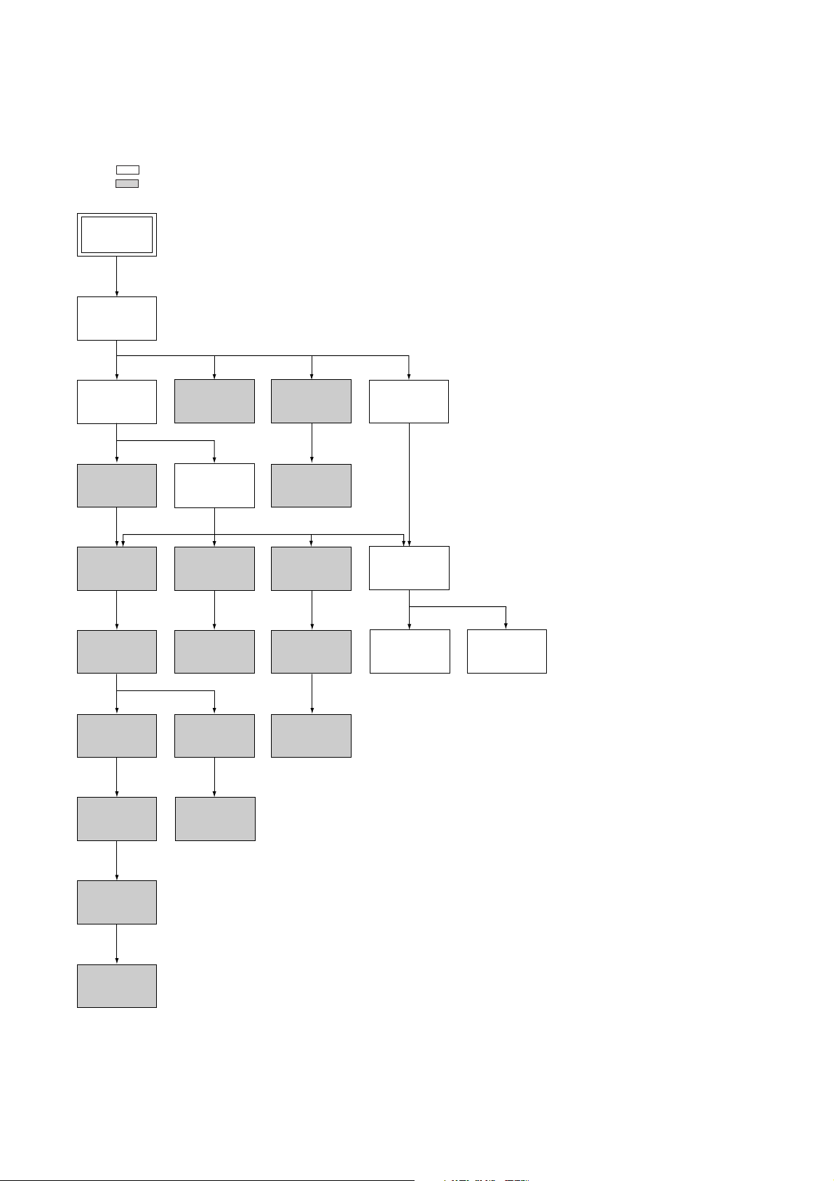
1. DISASSEMBLY
• This set can be disassembled in the order shown below.
Note: Pages in indicated pages in the SERVICE MANUAL.
Pages in indicated pages in the VHS MECHANICAL ADJUSTMENT MANUAL VI.
Set
Upper case
(Page 2-1)
Front Panel
Section
(Page 2-1)
FL Complete
Ass’y
(Page 13)
Retainer
Plate
(Page 22)
FL Slider
Block Ass’y
(Page 22)
Cam Gear
(Page 23)
Pinch Press
Block Ass’y
(Page 14)
Mechanism
Deck
(Page 2-3)
Rubber
Belt
(Page 15)
Capstan
Motor
(Page 15)
Cam Motor
Retainer
(Page 31)
Ground Shaft
Ass’y
(Page 13)
Drum
Ass’y
(Page 13)
Rubber
Belt
(Page 15)
Pully Gear
Ass’y
(Page 29)
Reel Direct
Ass’y
(Page 30)
Rear
Panel
(Page 2-2)
MA-402
Board
(Page 2-2)
Rotary
Switch
(Page 2-3)
Tuner
Unit
Rubber
Belt
(Page 15)
Slider
(Page 26)
Loading
Gear (T, S)
(Page 28)
Cam Motor
(Page 31)
– 4 –
SLV-EX50/EX80S/EX90S
V
Step 2
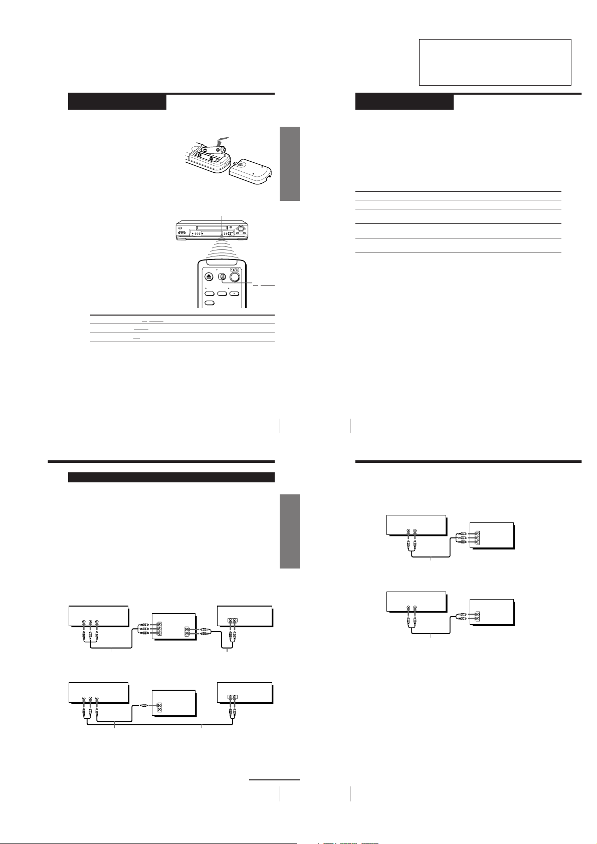
Setting up the remote commander
Inserting the batteries
Insert two size AA (R6) batteries by
matching the + and – on the batteries
to the diagram inside the battery
compartment.
Insert the negative (–) end first, then
push in and down until the positive
(+) end clicks into position.
Using the remote commander
You can use this remote
commander to operate this VCR
and a Sony TV. Buttons on the
remote commander marked with
a dot (•) can be used to operate
your Sony TV. If the TV does not
have the g symbol near the
remote sensor, this remote
commander will not operate the
TV.
To operate
the VCR
a Sony TV
Notes
• With normal use, the batteries should last about three to six months.
• If you do not use the remote commander for an extended period of time, remove
the batteries to avoid possible damage from battery leakage.
• Do not use a new battery with an old one.
• Do not use different types of batteries.
• Some buttons may not work with certain Sony TVs.
Set
VIDEO
T
to
TV/VIDEO
and point at the remote sensor on the VCR
and point at the remote sensor on the TV
Remote sensor
TV/VIDEO
SECTION 1
GENERAL
Getting Started
This section is a translated version
of Instruction Manual SLV-EX50AR/
EX80SAR/EX90SAR model.
Part number: 3-066-370-11
Step 3
Hookups
Selecting the best hookup option
There are many ways in which your VCR can be hooked up. To hook up
your VCR so that it works best for you, first scan through the table below.
Then use the accompanying diagrams and procedures on the following
pages to set up your VCR.
If your TV has audio/video inputs, refer to pages 7 and 8 for audio/video
(A/V) hookup. Then follow one of the hookups below.
If you have
Antenna only, no cable TV
Cable box with many scrambled
channels
No cable box, or cable box with only
a few scrambled channels
Cable box with only a few scrambled
channels, using an A/B switch
After you’ve completed the connections, follow the instructions for setup.
After you’ve completed the setup, you’re ready to use your VCR. Procedures
differ depending on the hookup you used. For an overview, refer to “Quick
reference to using the VCR” on the back cover.
Before you get started
• Turn off the power to all equipment.
• Do not connect the AC power cords until all of the connections are
completed.
• Be sure you make connections firmly. Loose connections may cause
picture distortion.
• If your TV doesn’t match any of the examples provided, see your nearest
Sony dealer or qualified technician.
Use
Hookup 1
Hookup 2
Hookup 3
Hookup 4
Refer to
Page 9
Page 10
Page 11
Page 12
Audio/video (A/V) hookup
If your TV has audio/video (A/V) input jacks, you will get a better picture
and sound if you hook up your VCR using these connections. If your TV
doesn’t have A/V inputs, see the following pages for antenna or cable
hookups.
If you’re not planning to use your VCR to record programs, you’re finished
setting up the VCR after you’ve made the connections shown on pages 7 and
8.
If you want to record off-air or off your cable TV system, complete these
connections first, and then go to the following pages for antenna or cable
hookups.
For SLV-EX90S AR and EX80S AR
For a true “home theater” experience, you should connect the audio outputs
of your VCR or TV to your stereo system.
A Use this hookup if your TV has stereo jacks
VCR Stereo receiver
R AUDIO L VIDEO
LINE OUT
Audio/video cable (not supplied)
B Use this hookup if your TV doesn’t have stereo jacks
VCR
R AUDIO L VIDEO
LINE OUT
TV
IN
VIDEO
AUDIO OUT
AUDIO
Audio cable (not supplied)
TV
IN
VIDEO
AUDIO
Getting Started
Pages 7 and 8
AUX IN
Stereo receiver
AUX IN
5
Getting Started
Getting Started
6
Step 3: Hookups (continued)
For SLV-EX50 AR
A Use this hookup if your TV has stereo jacks
AUDIO VIDEO
Audio/video cable (not supplied)
B Use this hookup if your TV doesn’t have stereo jacks
AUDIO VIDEO
Audio/video cable (not supplied)
VCR
VCR
LINE OUT
LINE OUT
TV
IN
VIDEO
AUDIO
TV
IN
VIDEO
AUDIO
Video cable (not supplied)
Note
• To play a tape in stereo, you must use the A/V connection.
Audio cable (not supplied)
continued
Getting Started
7
Getting Started
8
– 1-1 –
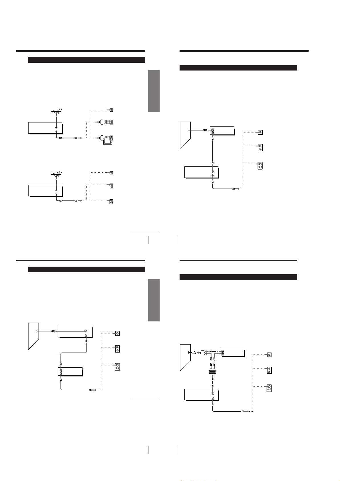
Hookup 1
Antenna hookup
Make the following connections if you’re using an antenna (if you don’t
have cable TV).
A Use this hookup if you’re using:
• VHF/UHF antenna (you get channels 2–13 and channels 14 and higher)
• UHF-only antenna (you get channels 14 and higher)
• Separate VHF and UHF antennas
Rear of TV
VHF/UHF
A
or
VCR
VHF/UHF
IN
OUT
B Use this hookup if you’re using a VHF-only antenna (you get
channels 2–13 only)
VCR
VHF/UHF
IN
OUT
If you cannot connect your antenna cable to the VCR directly
If your antenna cable is a flat cable (300-ohm twin lead cable), attach an external
antenna connector (not supplied) so you can connect the cable to the VHF/UHF IN
connector. If you have separate cables for VHF and UHF antennas, you should use a
U/V band mixer (not supplied). For details, see page 60.
VHF
B
UHF
or
VHF
C
UHF
Rear of TV
VHF/UHF
VHF
UHF
VHF
UHF
A
B
C
or
or
Page 9
Match the type of
connector on your
TV: A, B, or C.
Match the type of
connector on your
TV: A, B, or C.
For connector types
B and C, no UHF
connection is
required.
continued
Getting Started
Getting Started
9
Step 3: Hookups (continued)
Hookup 2
Hookup 4Hookup 4
Connecting a cable box with many scrambled
channels
Recommended use
Use this hookup if your cable system scrambles all or most channels.
What you can do with this hookup
• Record any channel by selecting the channel on the cable box
What you can’t do
• Record with the cable box turned off
• Record one channel while watching another channel
Wall
VCR
VHF/UHF
Getting Started
10
Cable box
IN
OUT
IN
OUT
or
or
Rear of TV
VHF/UHF
VHF
UHF
VHF
UHF
Match the type
A
of connector on
your TV: A, B, or
C.
For connector
B
types B and C, no
UHF connection
is required.
C
Page 10
Hookup 3
You have no cable box, or cable box with only a few
scrambled channels
Recommended use
Use this hookup if you do not have a cable box. Also use this hookup if your
cable system scrambles only a few channels.
What you can do with this hookup
• Record any unscrambled channel by selecting the channel on the VCR
What you can’t do
• Record scrambled channels that require a cable box
Wall
Connect this cable
directly to your TV
if you don’t have a
cable box.
Cable box
IN
OUT
VCR
VHF/UHF
IN
OUT
Rear of TV
or
or
VHF/UHF
VHF
UHF
UHF
Page 11
A Match the type
of connector
on your TV: A,
B, or C.
B
For connector
types B and C, no
UHF connection
is required.
C
continued
Getting Started
Step 3: Hookups (continued)
Hookup 4
Connecting a cable box with only a few scrambled
channels, using an A/B switch
Recommended use
By using an A/B switch (not supplied), this hookup allows you to record
both scrambled and unscrambled channels conveniently.
What you can do with this hookup
• Record any unscrambled channel by selecting the channel directly on the
VCR (the A/B switch is set to A)
• Record any scrambled channel by selecting the channel on the cable box
(the A/B switch is set to B)
What you can’t do
• Record one scrambled channel while watching another channel (the A/B
switch is set to B)
Wall
Splitter
A/B switch
VCR
Cable box
IN
OUT
A
B
VHF/UHF
IN
OUT
Rear of TV
VHF/UHF
or
or
VHF
UHF
VHF
Page 12
A
Match the type
of connector on
your TV: A, B,
or C.
B
For connector
types B and C,
no UHF
connection is
required.
C
Getting Started
11
– 1-2 –
12
Getting Started

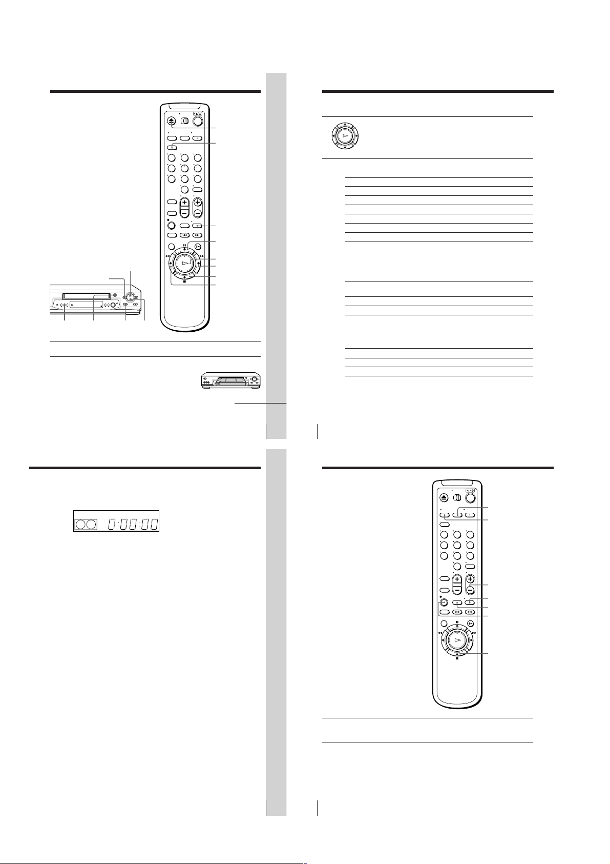
Step 4
Setting the RF unit
When connecting the VCR to the TV
using only the antenna cable, you must
set the RF UNIT switch on the rear of the
VCR so that the TV can receive the
correct signal from the VCR.
If you made A/V connections (pages 7
and 8), you can skip this step.
RF UNIT switch
1 Set the RF UNIT switch on the rear of the VCR to CH3 or CH4,
RF UNIT
CH3
CH4
whichever channel is not used in your area. If both are used, set the
switch to either channel.
• ]/1
2 Press ?/1 to turn on the VCR.
• TV/
3 Press TV/VIDEO to display the VIDEO indicator in the VCR’s
VIDEO
display window.
• CH
4 Press CH +/– to display a channel number in the display window.
Select an active channel number in your area.
123
456
789
0
?/1
TV/VIDEO
CH +/–
continued
Getting Started
Step 4: Setting the RF unit (continued)
5 Turn on your TV and set it to the channel you selected in step 1
(channel 3 or 4).
The channel you selected in step 4 appears on the TV screen. If the
channels change when you press CH +/–, you have made the
correct setting.
Whenever you use the VCR, set the TV to the channel selected in
step 1.
Step 5
Selecting a
language
You can change the on-screen display
language from Spanish to English.
Before you start...
• Turn on the VCR and the TV.
• Set the TV to the VCR channel
(channel 3 or 4). If your TV is
connected to the VCR using A/V
connections, set the TV to video input.
• Press TV/VIDEO to display the
VIDEO indicator in the VCR’s display
window.
MENU
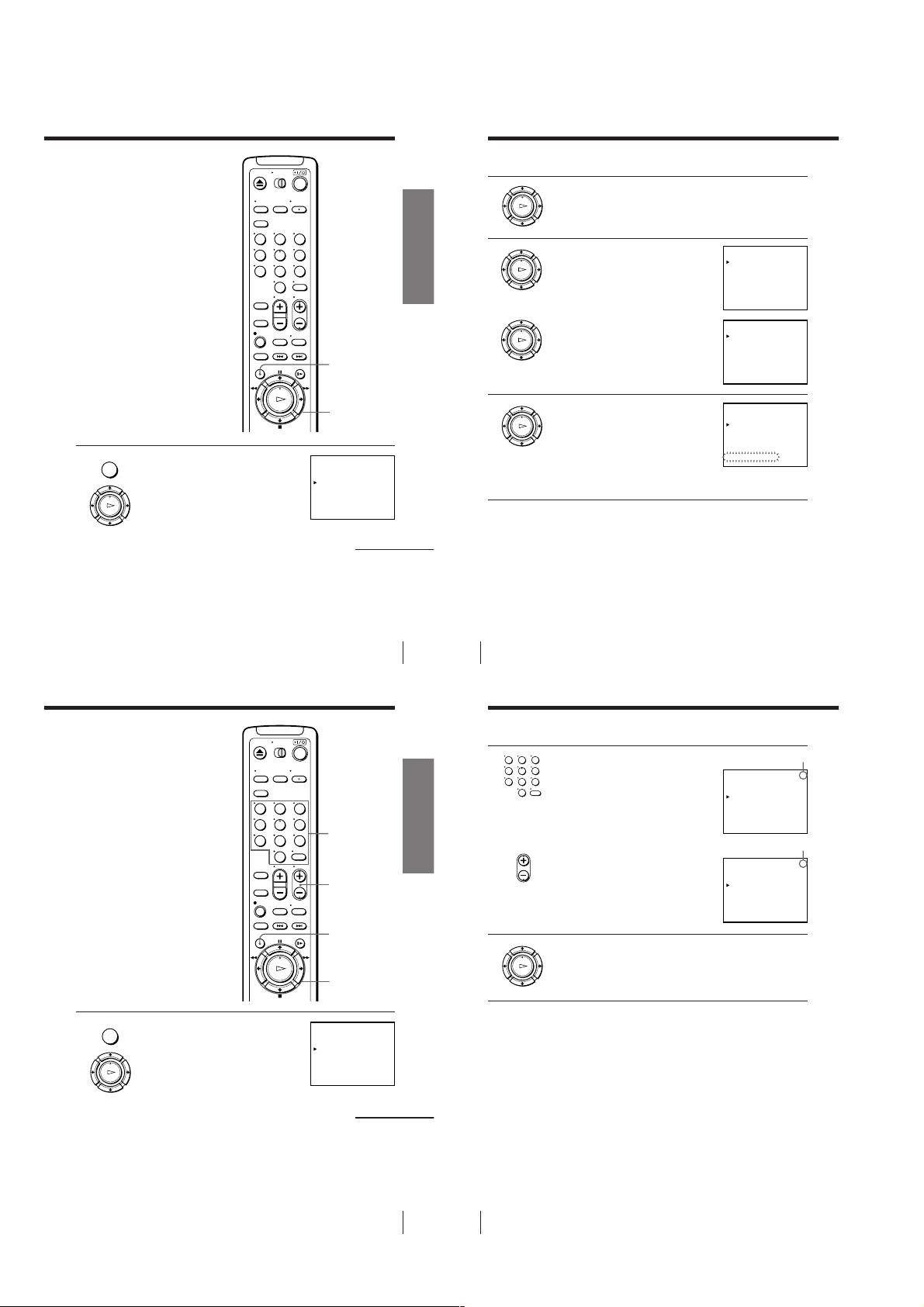
1 Press MENU, then press M/m to move the
2 Press M/m to select the desired language, then press OK.
cursor (B) to SELECCION DEL IDIOMA
and press OK.
PLAY
OK
PLAY
OK
Note
• The menu disappears automatically if you don’t proceed for more than a few
minutes.
MENU
OK
M/m
SELECCION DEL IDIOMA
ESPAÑOL
•
ENGLISH
SELECCIONAR : [ ]V v
FIN
Getting Started
:[ ]OK
13
Getting Started
Getting Started
14
Step 6
Presetting channels
First, we recommend that you preset the receivable channels in your area
using the One Touch Tuning function or SINTONIA AUTOMATICA in the
AJUSTE DE SINTONIA menu. Then, if some channels cannot be preset
automatically, set them manually. If there are any unwanted channels among
the preset ones, you can disable the channels.
Presetting all receivable
channels using the One
Touch Tuning function
ONE TOUCH
Press and hold ONE TOUCH TUNING on the VCR for more than
TUNING
three seconds.
The VCR starts presetting the channel.
The WAIT indicator goes off when all receivable channels are preset.
To check if the channels are preset correctly
Set the TV to the video channel and press CHANNEL +/– on the VCR. If
the TV screen changes to a different program each time you press
CHANNEL +/–, the channels are preset correctly.
Tip
• To stop the One Touch Tuning function, press ONE TOUCH TUNING or x STOP
on the VCR during the setting.
ONE TOUCH
TUNING
SP
CHANNEL +/–
APC
Getting Started
15
– 1-3 –
16
Getting Started
Presetting all receivable
OK
PLAY
OK
PLAY
OK
PLAY
OK
PLAY
OK
PLAY
channels automatically
If you have preset the channels using the
One Touch Tuning function, skip this
procedure.
Before you start…
• Turn on the VCR and the TV.
• Set the TV to the VCR channel
(channel 3 or 4). If your TV is
connected to the VCR using A/V
connections, set the TV to video input.
• Press TV/VIDEO to display the
VIDEO indicator in the VCR’s display
window.
123
456
789
0
MENU
Getting Started
Step 6: Presetting channels (continued)
2 Press M/m to select ANTENA/CABLE.
3 • To preset cable TV channels:
Press </, to set ANTENA/CABLE
to CABLE.
• To preset VHF and UHF channels:
Press </, to set ANTENA/CABLE
to ANT.
AJUSTE DE SINTONIA
ANTENA / CABLE
SINTONIA AUTOMATICA
SINT. MANUAL
AFT
SINTONIA FINA.
SELECCIONAR : [ ]V v
AJUSTAR
:[ ]B b
AJUSTE DE SINTONIA
ANTENA / CABLE
SINTONIA AUTOMATICA
SINT. MANUAL
AFT
SINTONIA FINA.
SELECCIONAR : [ ]V v
:[ ]B b
AJUSTAR
1CAN
ANT CABLE•
–+
•
NOSI•
1CAN
ANT CABLE•
–+
•
NOSI•
MENU
1 Press MENU, then press M/m to move the
Presetting/disabling
channels manually
Before you start…
• Turn on the VCR and the TV.
• Set the TV to the VCR channel
(channel 3 or 4). If your TV is
connected to the VCR using A/V
connections, set the TV to video input.
• Press TV/VIDEO to display the
VIDEO indicator in the VCR’s display
window.
cursor (B) to AJUSTE DE SINTONIA and
press OK.
PLAY
OK
123
456
789
0
OK
M/m/</,
AJUSTE DE SINTONIA
ANTENA / CABLE
SINTONIA AUTOMATICA
SINT. MANUAL
AFT
SINTONIA FINA.
SELECCIONAR : [ ]V v
:[ ]B b
AJUSTAR
Getting Started
Number
buttons,
ENTER
CH +/–
MENU
OK
M/m/</,
ANT CABLE•
–+
•
NOSI•
continued
1CAN
17
Getting Started
4 Press M/m to move the cursor (B) to
Getting Started
18
SINTONIA AUTOMATICA, then press
OK.
All receivable channels are preset in
numerical sequence. When no more
receivable channels can be found,
presetting stops and the picture from the
lowest numbered channel is displayed on
the TV screen.
Note
• The menu disappears automatically if you don’t proceed for more than a few
minutes.
AJUSTE DE SINTONIA
ANTENA / CABLE
SINTONIA AUTOMATICA
SINT. MANUAL
AFT
SINTONIA FINA.
POR FAVOR ESPERE
Step 6: Presetting channels (continued)
2 • To preset a channel:
123
456
789
3 Repeat step 2 to preset or disable channels as required, then press
1 Press the number buttons to enter the
0
• CH
channel number, then press ENTER.
2 Press </, to set SINT. MANUAL
to +.
• To disable a channel:
1 Press CH +/– to select the channel
number.
2 Press </, to set SINT. MANUAL
to –.
OK.
Channel to be preset
AJUSTE DE SINTONIA
ANTENA / CABLE
SINTONIA AUTOMATICA
SINT. MANUAL
AFT
SINTONIA FINA.
SELECCIONAR : [ ]V v
AJUSTAR
Channel to be disabled
AJUSTE DE SINTONIA
ANTENA / CABLE
SINTONIA AUTOMATICA
SINT. MANUAL
AFT
SINTONIA FINA.
SELECCIONAR : [ ]V v
AJUSTAR
:[ ]B b
:[ ]B b
1CAN
ANT CABLE•
–+
•
NOSI•
4CAN
ANT CABLE•
–+
•
NOSI•
5CAN
ANT CABLE•
–+
•
NOSI•
MENU
1 Press MENU, then press M/m to move the
cursor (B) to AJUSTE DE SINTONIA and
press OK.
PLAY
OK
AJUSTE DE SINTONIA
ANTENA / CABLE
SINTONIA AUTOMATICA
SINT. MANUAL
AFT
SINTONIA FINA.
SELECCIONAR : [ ]V v
AJUSTAR
:[ ]B b
1CAN
ANT CABLE•
–+
•
NOSI•
Note
• The menu disappears automatically if you don’t proceed for more than a few
minutes.
continued
Getting Started
19
– 1-4 –
20
Getting Started

If the picture is not clear
AJUSTE DE SINTONIA
:[ ]B b
ANTENA / CABLE
SINTONIA AUTOMATICA
SINT. MANUAL
SINTONIA FINA.
AFT
AJUSTAR
SELECCIONAR : [ ]V v
4CAN
ANT CABLE•
NOSI•
•
–+
1
AJUSTE DE SINTONIA
ANTENA / CABLE
SINTONIA AUTOMATICA
SINT. MANUAL
SINTONIA FINA.
AFT
4CAN
ANT CABLE•
NOSI•
•
–+
AJUSTAR : [ ]B b
1
AJUSTE DE SINTONIA
ANTENA / CABLE
SINTONIA AUTOMATICA
SINT. MANUAL
SINTONIA FINA.
AFT
4CAN
ANT CABLE•
NOSI •
•
–+
AJUSTAR : [ ]B b
1
AJUSTE DEL RELOJ
FIN :
AJUSTAR :[[]]OKV v
SELECCIONAR : [ ]B b
8
12
V I E2. . 001 :009AM2
AJUSTE DEL RELOJ
FIN :
AJUSTAR :[[]]OKV v
SELECCIONAR : [ ]B b
8
6
V I E2. . 001 :009PM2
Normally, the Auto Fine Tuning (AFT)
function automatically tunes in channels
clearly. If, however, the picture of a
channel is not clear, you can also use the
manual tuning function.
123
456
789
0
Number
buttons,
ENTER
Getting Started
Step 6: Presetting channels (continued)
2 Press the number buttons to select the
123
456
789
3 Press M/m to move the cursor (B) to
channel you want to fine-tune, then press
ENTER.
0
SINTONIA FINA.
PLAY
OK
The fine tuning meter appears.
Selected channel
MENU
1 Press MENU, then press M/m to move the
cursor (B) to AJUSTE DE SINTONIA and
press OK.
PLAY
OK
Step 7
Setting the clock
You must set the time and date on the
VCR to be able to use the timer
recording features properly.
Before you start...
• Turn on the VCR and the TV.
• Set the TV to the VCR channel
(channel 3 or 4). If your TV is
connected to the VCR using A/V
connections, set the TV to video input.
• Press TV/VIDEO to display the
VIDEO indicator in the VCR’s display
window.
123
456
789
0
MENU
OK
M/m/</,
AJUSTE DE SINTONIA
ANTENA / CABLE
SINTONIA AUTOMATICA
SINT. MANUAL
AFT
SINTONIA FINA.
SELECCIONAR : [ ]V v
:[ ]B b
AJUSTAR
Getting Started
ANT CABLE•
–+
•
NOSI•
continued
1CAN
21
Getting Started
4 Press </, to adjust to a clearer picture,
Getting Started
22
then press OK.
PLAY
OK
Note that the AFT setting switches to NO.
Tip
• To select the channel in step 2 above, you can also use the CH +/– buttons. In this
case, you don’t need to press ENTER.
Notes
• The menu disappears automatically if you don’t proceed for more than a few
minutes.
• When adjusting FINE TUNING, the menu may become difficult to read due to
interference from the picture being received.
Step 7: Setting the clock (continued)
3 Press , to select the month and press
4 Set the year, hour, and minute in sequence,
M/m to set the month.
PLAY
OK
using , to select the item to be set, and
PLAY
M/m to select the digits.
OK
The day of the week is set automatically.
5 Press OK to start the clock.
PLAY
OK
Tip
• To change the digits during the setting, press < to return to the item to be changed,
and select the digits by pressing M/m.
Note
• The menu disappears automatically if you don’t proceed for more than a few
minutes.
MENU
1 Press MENU, then press M/m to move the
2 Press M/m to set the date.
cursor (B) to AJUSTE DEL RELOJ and
press OK.
PLAY
OK
PLAY
The day of the week is set automatically.
OK
MENU
OK
M/m/</,
AJUSTE DEL RELOJ
LUN2. . 001 : 001
1
SELECCIONAR : [ ]B b
AJUSTAR :[[]]OKV v
FIN :
AJUSTE DEL RELOJ
DOM2. . 001 : 001AM2
8
SELECCIONAR : [ ]B b
AJUSTAR :[[]]OKV v
FIN :
12
AM
12
continued
Getting Started
23
– 1-5 –
24
Getting Started
Basic Operations
OK
PLAY
Playing a tape
Playing a tape (continued)
123
456
789
0
H PLAY
COLOR
SYSTEM
m REW
A EJECT
X PAUSE
M FF
x STOP
1 Turn on your TV and set it to the video channel.
2 Insert a tape.
The VCR turns on and starts playing
automatically if you insert a tape with its
safety tab removed.
Z EJECT
CLEAR
DISPLAY
X PAUSE
H PLAY
M FF
x STOP
m REW
continued
Basic Operations
3 Press H PLAY.
When the tape reaches the end, it will rewind automatically.
Additional tasks
To
Stop play
Pause play
Resume play after pause
Fast-forward the tape
Rewind the tape
Eject the tape
To set the color system
If streaks appear during playback, press COLOR SYSTEM on the VCR to
conform to the system that the tape was recorded in. (Normally, the color
system is correctly set whenever the tape is inserted.)
If your tape was recorded in
PAL-N
NTSC
To play an NTSC-recorded tape
Set NTSC PB in the AJUSTES ESPECIALES according to the color system of
your TV. For details, see page 56.
If your TV is
PAL-N
NTSC 3.58
* If you are using a multi-system TV, set the NTSC PB in the AJUSTES
ESPECIALES to NTSC 3.58 for better picture quality.
Press
x STOP
X PAUSE
X PAUSE or H PLAY
M FF during stop
m REW during stop
Z EJECT
Press COLOR SYSTEM until the indicator below
appears in the display window.
PAL
NTSC
Set NTSC PB to
ON PAL-N TV
NTSC 3.58
Basic Operations
To use the time counter
Press CLEAR at the point on the tape that you want to find later. The counter
in the display window resets to “0:00:00.” Search for the point afterwards by
referring to the counter.
SP
To display the counter on the TV screen, press DISPLAY. Press DISPLAY
again and the counter will disappear from the TV screen.
Notes
• The counter resets to “0:00:00” whenever a tape is reinserted.
• The counter stops counting when it comes to a portion with no recording.
• If a tape has portions recorded in both PAL-N and NTSC systems, the time counter
reading will not be correct. This is due to the difference between the counting
cycles of the two color systems.
• Depending on your TV, the following may occur while playing an NTSC-recorded
tape:
– the picture is black and white
– the picture shakes
– no picture appears on the TV screen
– black streaks appear horizontally on the TV screen
– the color density increases or decreases.
• Tapes recorded in the LP mode of other NTSC system VCRs can be played back on
this VCR but the picture quality cannot be guaranteed.
• While setting the menu on the TV screen, you cannot use the H PLAY, X PAUSE,
M FF, m REW, or x STOP button.
APCVIDEO
25
Basic Operations
Basic Operations
26
Recording TV
programs
INPUT SELECT
TV/VIDEO
123
456
789
0
CH +/–
DISPLAY
REC SPEED
z REC
x STOP
1 Turn on your TV and set it to the video channel.
To record from a cable box, turn it on.
2 Insert a tape with its safety tab in place.
Basic Operations
27
– 1-6 –
Basic Operations
28

• CH
AM
3 Press CH +/– to select the channel you want to record.
4 Press REC SPEED to select the tape speed. (SP or LP for the PAL-N
REC SPEED
5 Press z REC to start recording.
color system, and SP or EP for the NTSC color system)
LP (Long Play) provides recording time twice as long as SP
(Standard Play). EP (Extended Play) provides recording time three
times as long as SP. However, SP produces better picture and audio
quality.
REC
SP
LP
APCVIDEO
APCVIDEO
The recording indicator lights up red in the display window.
Recording indicator
To stop recording
Press x STOP.
To check the remaining tape length
Press DISPLAY. The white bar indicates the approximate length of tape
remaining.
C
F
0 : 00 : 22
Remaining tape length
Time counter
SP
Tape speed*
* Appears for a few seconds when the ON SCREEN DISPLAY is pressed and when
the mode is changed.
LP
APCVIDEO
continued
Basic Operations
Basic Operations
29
Recording TV programs (continued)
To watch another TV program while recording
1 Press TV/VIDEO to turn off the VIDEO indicator in the display
window.
2 If the TV is connected to the VCR using an audio/video cable, set the
TV to TV input. If the TV is connected to the VCR using only the
antenna cable, skip this step.
3 Select another channel on the TV.
To save a recording
To prevent accidental erasure, break off the
safety tab as illustrated. To record on the tape
again, cover the tab hole with adhesive tape.
Tips
• To select a channel, you can use the number buttons on the remote commander.
Enter the channel number, then press ENTER.
• You can select a video source from the LINE-1 IN or LINE-2 IN (SLV-EX90S AR/
EX80S AR only) jacks using the INPUT SELECT or CH +/– buttons.
• The display appears on the TV screen indicating information about the tape, but the
information won’t be recorded on the tape.
• If you don’t want to watch TV while recording, you can turn off the TV. When using
a cable box, make sure to leave it on.
• You can have the VCR stop recording automatically after starting at a specified
time. For details, see “Setting the recording duration time” on page 47.
Notes
• The display doesn’t appear during still (pause) mode or slow-motion playback.
• If a tape has portions recorded in both PAL-N and NTSC systems, the time counter
reading will not be correct. This discrepancy is due to the difference between the
counting cycles of the two color systems.
• When you insert a non-standard commercially available tape, the remaining time
may not be correct.
• It may take up to one minute for the VCR to calculate and display the remaining
tape length after you press DISPLAY.
Basic Operations
30
Safety tab
Recording TV
programs using
the Easy Timer
function
The Easy Timer function allows you to
make a timer recording of a program
without turning on your TV. Set the
recording timer to record only one
program that will be broadcast within
the next 24 hours using the EASY
TIMER knob. If the VCR clock has not
been set, you can also set the clock
before setting the timer recording.
Setting the Easy Timer
Before you start…
• When using a cable box, turn it on.
• Insert a tape with its safety tab in
place. Make sure the tape is longer
than the total recording time.
CHANNEL +/–
REC SPEED
SP/LP (SP/EP)
EASY TIMER
1 Push the EASY TIMER knob.
EASY TIMER
knob
The START indicator appears in the display window.
If the clock has not been set,
“–:– –” appears. Go to step 2
in “Setting or changing the
Easy Clock” on page 33.
123
456
789
0
SP
CLEAR
Number
buttons
ENTER (AM/PM)
EASY
TIMER
CH +/–
REC SPEED
START
AM
APC
Basic Operations
Recording TV programs using the Easy Timer function (continued)
EASY TIMER
2 Set the recording start time by turning the EASY TIMER knob
3 Push the EASY TIMER knob to confirm the start time setting.
4 Set the recording stop time in the same way as in step 2, then push
5 Turn the EASY TIMER knob clockwise or counterclockwise to select
6 Push the EASY TIMER knob to confirm the setting.
clockwise or counterclockwise to increase or decrease the time by 15
minutes.
Press CHANNEL +/– to
inrease or decrease the time
by a minute.
Press ENTER (AM/PM) to
change AM and PM.
EASY TIMER
The STOP indicator appears.
EASY TIMER
the EASY TIMER knob.
A channel number flashes.
EASY TIMER
the channel you want to record.
To select the tape speed, press
REC SPEED.
REC SPEED
SP/LP
(SP/EP)
EASY TIMER
The t indicator appears in
the display window and the
VCR stands by for recording.
START
SP
AM
APC
SP
SP
SP
LP
STOP
PM
APC
APC
APC
continued
Basic Operations
31
– 1-7 –
Basic Operations
32
Setting or changing the
EASY TIMER
Easy Clock
When “–:– –” is displayed in the VCR’s
display window, the VCR clock has not
been set. You need to set the clock using
the Easy Clock function before setting
the timer. You can also change the
current time using the Easy Clock
function.
123
456
789
0
Number
buttons
ENTER (AM/PM)
EASY
TIMER
CH +/–
Recording TV programs using the Easy Timer function (continued)
3 Push the EASY TIMER knob to finish setting the clock.
The VCR enters the timer recording setting mode.
To continue the Easy Timer
setting, go to step 2 in
“Setting the Easy Timer” on
page 31.
To quit the Easy Timer setting mode without changing any settings,
push the EASY TIMER knob repeatedly until the
appears in the display window.
START STOP
SP
PM
APC
indicator
t
EASY TIMER
knob
EASY TIMER
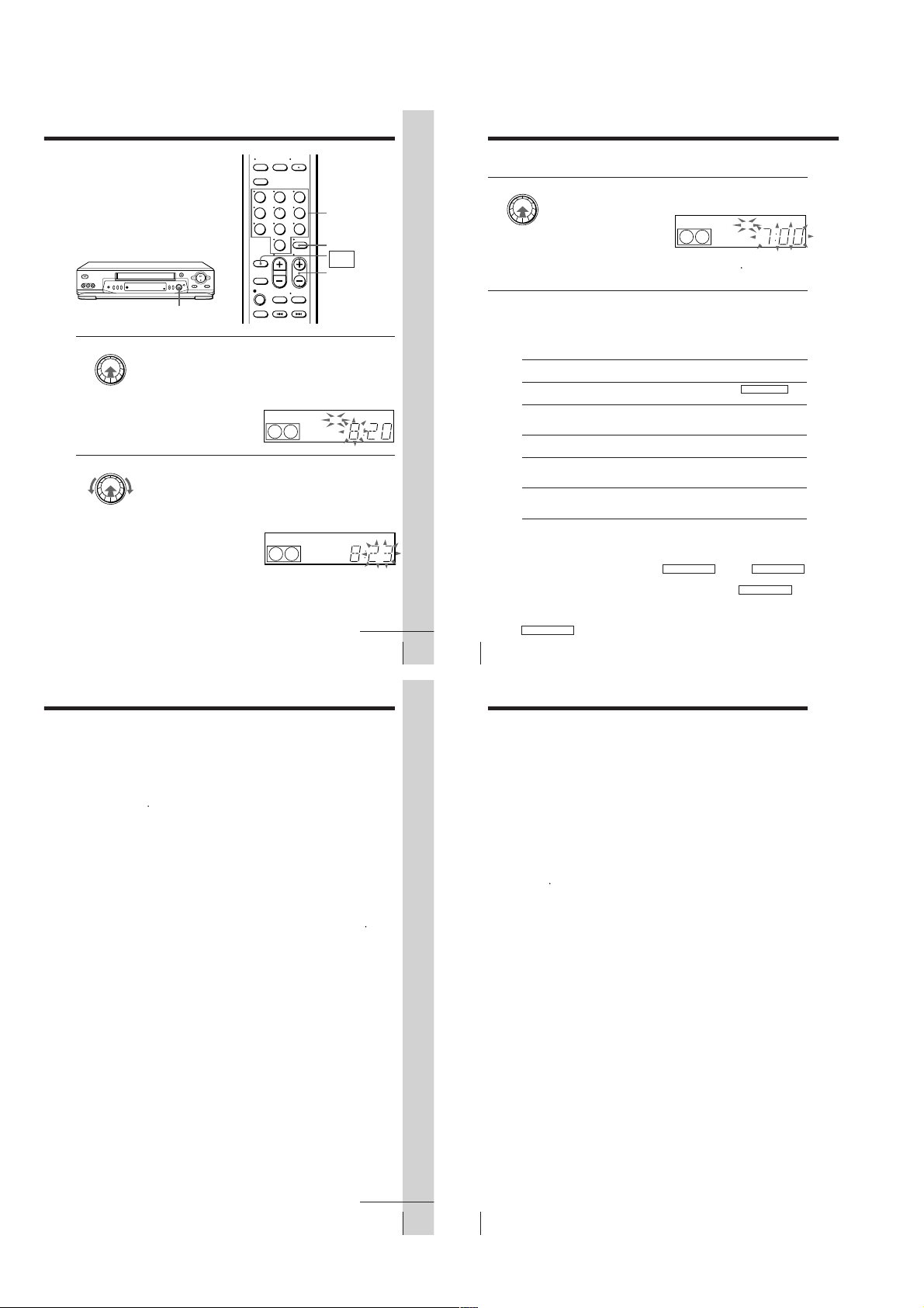
1 • When “–:– –” is displayed in the display window, push the
EASY TIMER
2 Set the current time using the EASY TIMER knob.
EASY TIMER knob.
• To change the clock setting, push and hold the EASY TIMER knob
on the VCR for more than three seconds.
The CLOCK indicator and the current clock setting appear in the
display window.
1 Turn the EASY TIMER knob clockwise or counterclockwise to
enter the current hour.
2 Push the EASY TIMER knob to confirm the hour setting.
3 Turn the EASY TIMER knob to increase or decrease the minutes
setting by a minute.
Press ENTER (AM/PM) to
change AM and PM.
SP
SP
CLOCK
CLOCK
START
AM
APC
START
AM
Basic Operations
To stop recording
To stop the VCR while recording, press x STOP.
To check or change the timer setting
Push the EASY TIMER knob repeatedly until the setting you want to check
or change flashes. Then re-enter the new setting, if necessary. If you do not
want to change any of the settings, push the EASY TIMER knob repeatedly
indicator appears in the display window.
until the
t
You can also change the timer setting using the PROGRAM./VERIF. menu.
For details, see page 50.
To cancel the timer setting
To cancel the Easy Timer setting while entering a setting, press CLEAR on
the remote commander or press CHANNEL + and – on the VCR at the same
time.
To use the VCR after setting the timer
To use the VCR before a timer recording begins, just press ?/1. The
indicator turns off and the VCR switches on. Remember to press ?/1 to reset
the VCR to the timer recording standby mode after using the VCR.
You can also do the following tasks while the VCR is recording:
• Reset the counter.
• Display tape information on the TV screen.
• Check the timer settings.
• Watch another TV program.
To watch the recorded program right after recording with the Easy
Timer
The SEARCH MODE indicator starts flashing when the VCR finishes the
Easy Timer recording. To watch the recorded program, push the EASY
TIMER knob. The VCR turns on, starts searching, then automatically starts
playback from the beginning of the recording. For details, see page 40.
APC
continued
t
Basic Operations
33
Basic Operations
To set the timer and clock setting using the remote commander
You can also use the remote commander to set the Easy Timer and Easy
Clock. The operations on the VCR and the remote commander correspond as
follows:
Basic Operations
34
To
Confirm the setting and go to
the next setting
Change the time by 15 minutes
(in START/STOP mode)
Change the time by one minute
(in START/STOP mode)
Select the channel
Change the hour/minute by
one hour/minute (in CLOCK
mode)
You can also use the number buttons to set the clock, start and stop times,
and the channel you want to record. Just press the number buttons to enter
the hours and minutes. For example:
• To set the clock to “8:20”, press 0, 8, EASY TIMER , 2, 0 and EASY TIMER
in sequence.
• To set the start or stop time to “8:20”, press 0, 8, 2, 0 and EASY TIMER in
sequence.
If you make a mistake, re-enter the correct digits before pressing
EASY TIMER .
Do this on the VCR
Push the EASY TIMER
knob
Turn the EASY TIMER
knob or hold CHANNEL
+/– down
Press CHANNEL +/–
Turn the EASY TIMER
knob or press
CHANNEL +/–
Turn the EASY TIMER
knob or press
CHANNEL+/–
Do this on the remote
commander
Press EASY TIMER
Hold CH +/– down
Press CH +/–
Press CH +/– or INPUT
SELECT
Press CH +/–
Recording TV programs using the Easy Timer function (continued)
Tips
• To record from a source connected to the LINE-1 IN or LINE-2 IN (SLV-EX90S AR/
EX80S AR only) jacks, press INPUT SELECT or CH +/– or turn the EASY TIMER
knob to display “L1” or “L2” (SLV-EX90S AR/EX80S AR only) in the display
window.
• To record NTSC signals, set the tape speed to SP or EP. To set to the EP mode,
display “LP” in the display window.
Notes
• You cannot set the Easy Timer if eight programs have already been set.
• You can set the timer for only one program using the Easy Timer function. If you
want to set the timer for other programs, use the PROGRAM./VERIF. menu. For
details, see page 37.
• You cannot set the date using the Easy Timer function. Set the date using the
AJUSTE DEL RELOJ menu if you want to set the timer with the menu. For details,
see page 23.
• The t indicator flashes in the display window when you complete the setting with
no tape inserted.
continued
Basic Operations
35
– 1-8 –
Basic Operations
36

Setting the timer
PROGRAM. / VERIF.3V I E
9.82
FECHA INICIO FIN CANAL
0. 9
DOM
–– : –– : ––––
SP
–– : –– : –––––––. –
–– : –– : –––––––. –
–– : –– : –––––––. –
–– : –– : –––––––. –
–– : –– : –––––––. –
–– : –– : –––––––. –
–– : –– : –––––––. –
manually
You can preset up to eight programs at a
time.
Before you start…
• Check that the VCR clock is set to the
correct time.
• Insert a tape with its safety tab in
place. Make sure the tape is longer
than the total recording time.
• Turn on your TV and set it to the
video channel.
123
456
789
0
?/1
INPUT SELECT
CH +/–
MENU
Basic Operations
Setting the timer manually (continued)
2 Set the date, start and stop times, channel
3 Press , to confirm the setting.
number, and tape speed:
PLAY
OK
1 Press , to select each item in turn.
2 Press M/m to set each item.
To correct a setting, press < to return to
that setting and reset it.
To record the same program every day or the same day every week,
press m while the date is flashing. For details, see “Daily/weekly
recording” on page 39.
INPUT
To record from a source connected to the LINE-1 IN or LINE-2 IN
SELECT
(SLV-EX90S AR/EX80S AR only) jacks, press INPUT SELECT or CH
+/– to display “L1” or “L2” (SLV-EX90S AR/EX80S AR only) in the
“CANAL” position.
PLAY
The cursor (B) appears at the beginning of the line. To enter another
OK
setting, move the cursor to the next line and repeat step 2.
MENU
1 Press MENU and select PROGRAM./
VERIF., then press OK.
PLAY
OK
Daily/weekly recording
In step 2 above, press m to select the recording pattern. Each time you press
m, the indication changes as shown below. Press M to change the indication
in reverse order.
the current date t DOM-SAB (Sunday to Saturday) t
LUN-SAB (Monday to Saturday) t LUN-VIE (Monday to Friday) t
TODOS SAB (every Saturday) t ..... t TODOS LUN (every Monday) t
TODOS DOM (every Sunday) t 1 month later t (dates count down) t
the current date
Tips
• To set the channel, you can also use the CH +/– or number buttons.
• To set the tape speed, you can also use the REC SPEED button.
• To record NTSC signals, set the tape speed to SP or EP. To set to the EP mode, display
“LP” in the tape speed position.
Note
• The t indicator flashes in the display window when you press ?/1 with no tape
inserted.
OK
M/m/</,
PROGRAM. / VERIF.–V I E
FECHA INICIO FIN CANAL
–. ––– : –– : –––––
9.82
–– : –– : –––––––. –
–– : –– : –––––––. –
–– : –– : –––––––. –
–– : –– : –––––––. –
–– : –– : –––––––. –
–– : –– : –––––––. –
–– : –– : –––––––. –
continued
Basic Operations
37
Basic Operations
4 Press OK.
PLAY
OK
5 Press ?/1 to turn off the VCR.
Basic Operations
38
Search Operations
• ]/1
To stop recording
To stop the VCR while recording, press x STOP.
indicator appears in the display window and the VCR
The
t
stands by for recording.
To record from other equipment, leave the connected equipment
switched on.
Searching for the beginning of an
Easy Timer recorded program
If you record a program using the Easy
Timer function, you can easily find the
beginning of the recording with the
SEARCH MODE function. The SEARCH
MODE indicator flashes when the VCR
finishes making an Easy Timer
recording.
Push the EASY TIMER knob.
The VCR turns on, rewinds to the beginning of the recorded program and
starts playback automatically. The SEARCH MODE indicator turns off.
Tip
• You can start the SEARCH MODE function after the flashing of the SEARCH
MODE indicator has been stopped. The flashing stops when you turn on the VCR
and press the SEARCH MODE button (Do not press any button at this point,
otherwise this SEARCH MODE function will be canceled). To start the SEARCH
MODE function, press the SEARCH MODE button repeatedly until the SEARCH
MODE indicator flashes. Push the EASY TIMER knob. The VCR rewinds and starts
playback automatically.
If you continue to press the SEARCH MODE button while the SEARCH MODE
indicator is flashing, you can enter other search operations (For details, see the
following pages). Each press of the SEARCH MODE button changes the search
operations as follows:
REMAIN BLANK INDEX TIME Off
EASY TIMER
knob
SEARCH MODE
Note
• This SEARCH MODE function will be canceled (the SEARCH MODE indicator
turns off) if:
– The VCR starts recording other programs.
– You press the H PLAY, M FF, m REW or A EJECT button while the VCR is
on.
Basic Operations
39
Search Operations
40
– 1-9 –

Searching for the
current position
on a tape
This feature enables you to find the
current position on a tape as well as the
remaining time of the tape.
1
Press SEARCH MODE repeatedly until the
REMAIN indicator appears in the display
window as shown on the right.
The SEARCH MODE indicator lights up.
2
Push the EASY TIMER knob to display
the tape meter on the TV screen.
The SEARCH MODE indicator turns off.
A cursor (x) indicates the current position
on the tape.
“REMAIN” and the remaining time of the tape appear in the display window in
the following order:
To stop the Search function
Press x STOP.
Notes
• To display the remaining time correctly you may have to select the SELEC DE CINTA in the
AJUSTES ESPECIALES according to the type of the tape that you are using. For details, see
page 56.
• In step 2, the VCR automatically rewinds and fast-forwards the tape only if you press the
SEARCH MODE button right after you insert a tape. This is so that the VCR can measure the
current position on the tape.
• You cannot use this function during any recording mode.
RE- MAIN
SP
SP
POSICIÓN DE LA CINTA
– – – – – – – – – – – – – – – –
Tape meter
0:15 (remaining
time of the tape)
EASY TIMER
knob
SEARCH MODE
START
APC
n
START
APC
Search Operations
Searching using
the Blank Search
function
This feature enables you to find a blank
section on your tape.
1 Press SEARCH MODE repeatedly until the
BLANK indicator appears in the display
window.
The SEARCH MODE indicator lights up.
2 Push the EASY TIMER knob on the VCR.
The SEARCH MODE indicator turns off.
The VCR fast-forwards to the end of the
tape. Then, the VCR rewinds the tape to
the last recorded program. After a few
seconds, the VCR starts playback and
stops at the beginning of the blank
section.
“BLANK” and the remaining time of the
blank section appear alternately in the
display window for about one minute.
To stop searching
To stop the VCR while searching for a blank section, press x STOP.
Notes
• To display the remaining time correctly you may have to select the SELEC DE CINTA in the
AJUSTES ESPECIALES according to the type of the tape that you are using. For details, see
page 56.
• In step 2, “FULL” will appear in the display window for about one minute, if:
– there is no blank section available on the tape.
– the remaining time of a blank section is less than one minute.
• The VCR can only detect the blank section between the end of the tape and the end of the last
recorded program.
Last recorded
program
41
Search Operations
42
Blank section
End of tape
SP
SP
EASY TIMER
knob
SEARCH MODE
START
APC
START
APC
n
APC
Searching using
the index
function
The VCR marks the tape with an index
signal at the point where each recording
begins. Use these signals as references to
find a specific recording. The VCR can
search up to 99 index signals ahead of or
behind the current position. You can
either use the INDEX SEARCH buttons
on the remote commander or the
SEARCH MODE button and EASY
TIMER knob on the VCR.
Before you start…
• Turn on the VCR and the TV.
• Set the TV to the video channel.
Using the INDEX SEARCH
buttons on the remote
commander
1
Insert an indexed tape into the VCR.
2
Press ./> INDEX SEARCH repeatedly to specify how many
index signals ahead or behind you want to search:
• To search ahead, press > INDEX
SEARCH.
• To search backwards, press . INDEX
SEARCH.
The VCR starts searching and the index
number on the TV screen counts down to zero.
Playback starts from the point about five
seconds ahead of the specified index mark.
INDICE
BUSQUEDA
./>
INDEX
SEARCH
8
Searching using the index function (continued)
Using the SEARCH MODE
button and EASY TIMER
knob on the VCR
1 Press SEARCH MODE on the VCR repeatedly until “INDEX” appears
in the VCR’s display window (the SEARCH MODE indicator lights up).
SP
2 Turn the EASY TIMER knob to specify how many index signals ahead
or behind you want to search:
• To search ahead, turn the EASY TIMER knob clockwise.
• To search backwards, turn the EASY TIMER knob counterclockwise.
SP
3 Push the EASY TIMER knob.
The VCR starts searching. Playback starts (the SEARCH MODE
indicator turns off) from the point about five seconds ahead of the
specified index mark.
To stop searching
Press x STOP.
Note
• No index signal will be added when recording starts from recording pause.
However, an index signal will be marked if you change the channel during
recording pause.
EASY TIMER
knob
SEARCH MODE
APC
START
APC
continued
Search Operations
43
– 1-10 –
Search Operations
44

Searching using the Time Search
function
You can easily find a specific point on a
tape by using the Time Search function.
For example, you can find a recorded
section 15 minutes ahead of or behind
the current position of a tape by using
the Time Search function.
1 Press SEARCH MODE repeatedly until “TIME” appears in the display
window (the SEARCH MODE indicator lights up).
SP
2 Turn the EASY TIMER knob clockwise or counterclockwise to set the
length of time you want the VCR to fast-forward or rewind the tape.
Each turn on the knob increases or decreases the duration by 15
minutes.
For example, if you want to watch a recorded section 15 minutes ahead
of the current position, turn the EASY TIMER knob once clockwise.
To change the time by one
minute, press CHANNEL
+/–.
3 Push the EASY TIMER knob.
The VCR starts searching and the tape counter starts counting until it
reaches the specified point.
The VCR starts playback automatically when the tape counter reaches
the specified point (the SEARCH MODE indicator turns off).
To stop searching
Press x STOP.
Tip
• The VCR can search up to three hours ahead of or behind the current position of a
tape.
SP
SP
EASY TIMER
knob
SEARCH MODE
APC
APC
APC
Additional Operations
Playing/searching
at various speeds
H PLAY
m REW M FF
Playback options
View the picture during fastforward or rewind
Play at high speed
Play at twice the normal speed
Play in slow motion
Play frame by frame
Rewind and start play
To resume normal playback
Press H PLAY.
Tips
• Adjust the picture using the TRACKING +/– buttons on the VCR if:
– streaks appear while playing in slow motion.
– the picture shakes during pause.
To set tracking to the center position, press both buttons (+/–) at the same time.
• If noise appears during pause or frame-by-frame playback, first switch to the slow
motion playback, then adjust the picture using TRACKING +/– on the VCR.
Notes
• The sound is muted during these operations.
• In LP or EP mode, noise may appear or there may be no color.
• The picture may show noise when playing at high speed in reverse.
Operation
During fast-forward, hold down M FF down. During
rewind, hold down m REW.
• During playback, press M FF or m REW
remote commander.
• During playback, hold down M FF or m REW.
When you release the button, normal playback resumes.
During playback or pause, press × 2.
During playback or pause, press y SLOW.
During pause, press M FF or m REW
commander. Hold down the button to play one frame each
second.
While the tape is stopped, hold down 0 REW
and press H PLAY on the VCR.
×2
y SLOW
H PLAY
M FF
m REW
on the
on the remote
on the VCR
Setting the
recording
duration time
After you have started recording in the
normal way, you can have the VCR stop
recording automatically after a specified
duration.
1 While recording, press z REC.
The t indicator appears in the display window.
2 Press z REC repeatedly to set the duration.
Each press advances the time in increments of 30 minutes.
The tape counter decreases minute by minute to 0:00, then the VCR
stops recording and turns off automatically.
To extend the duration
Press z REC repeatedly to set to the new duration.
To cancel the duration
Press z REC repeatedly until the t indicator turns off and the VCR returns
to normal recording mode.
To stop recording
To stop the VCR while recording, press x STOP.
0:30 1:00 6:005:30 Normal recording
123
456
789
0
SP
Search Operations
z REC
APCVIDEO
Additional Operations
45
Additional Operations
46
Synchronized recording
(SLV-EX90S AR only)
The Synchronized Recording feature enables you to record from the
connected equipment such as a satellite tuner, a cable TV decoder or a TV
that has a timer function. Once you set the timer on the other equipment, the
VCR will start recording the program synchronized with the timer.
Connections necessary to use this function
Connect the other equipment to the LINE-1 IN jacks of this VCR.
This VCR (Recorder)
LINE-1 IN
VMC-810HG audio/video cable (not supplied)
: Signal flow
How to make a Synchronized recording
SYNCHRO
REC
REC SPEED
SP/LP (SP/EP)
1 Press INPUT SELECT or CH +/– on the remote commander to display
“L1” in the display window.
2 Set the timer on the equipment to the time of the program you want to
record, then turn it off.
3 Insert a tape with its safety tab in place. Make sure the tape is longer
47
Additional Operations
48
than the total recording time.
Satellite tuner, etc.
LINE OUT
– 1-11 –

4
Press REC SPEED to select the tape speed (SP or LP for the PAL-N color
system, and SP or EP for the NTSC color system).
5
Hold down SYNCHRO REC for more than two seconds.
The SYNCHRO REC button lights up and the VCR stands by for
recording.
The VCR automatically turns on and starts recording when it receives
video/audio signals from the connected equipment.
To cancel the Synchronized recording
Press SYNCHRO REC so that the button’s light turns off.
To stop recording
Press x STOP while recording.
The VCR automatically stops recording when the tape reaches the end or
when the other equipment stops transmitting the video/audio signals.
Notes
• Some TVs or other equipment automatically turn off in a certain amount of time if
you do not operate it after it turns on with the timer. In this case the Synchronized
Recording also stops automatically.
• The Synchronized Recording starts and stops according to the signals from the
connected equipment. Refer also to the instruction manual of the connected
equipment for information about its timer function.
• Some equipment keeps transmitting signals even though the power is off. In this
case, the Synchronized Recording feature does not work because the VCR will not
be able to know when to start recording. To record the program, set the timer on the
VCR. If you use a satellite tuner or a cable TV decoder, make sure to turn it on. For
details, see “Setting the timer manually”.
• If the settings for timer recording and Synchronized Recording overlap, the
program that starts first has priority and the second program starts recording only
after the first program has finished.
• To record NTSC signals, set the tape speed to SP or EP. To record in the EP mode, set
the tape speed to “LP”.
Checking/
changing/
canceling timer
settings
Before you start…
• Turn on your TV and set it to the
video channel.
1 Press ?/1 to turn on the VCR.
2 Press MENU, then press M/m to select
PROGRAM./VERIF. and press OK:
• If you want to change or cancel a setting,
go on to the next step.
• If you do not need to change or cancel the
settings, press OK, then turn off the VCR to
return to recording standby.
123
456
789
0
?/1
CLEAR
MENU
OK
M/m/</,
PROGRAM. / VERIF.3V I E
FECHA INICIO FIN CANAL
0. 9 9
DOM
2.
10 11MAR 10
LUN
– 3
VIE
TODOS
DOM
8:00PM:00PM53
:00AM:03AM02
2:00PM:00PM06
7
6:30AM:00AM24
–– : –– : –––––––. –
–– : –– : –––––––. –
–– : –– : –––––––. –
–– : –– : –––––––. –
9.82
SP
LP
LP
LP
Additional Operations
3
Press M/m to select the setting you want to change or cancel:
• To change the setting, press </, to select the item you want to
change, and press M/m to reset it. Then, press , repeatedly until the
cursor (”) appears at the beginning of the line.
• To cancel the setting, press CLEAR.
4
Press OK.
If any timer settings remain, turn off the VCR to return to recording
standby.
When the timer settings overlap
The program that starts first has priority and the second program starts
recording only after the first program has finished. If the programs start at
the same time, the program listed first in the menu has priority.
Program 1
Program 2
will be cut off
49
Additional Operations
50
Recording stereo and bilingual
programs (SLV-EX90S AR/EX80S AR
only)
Recording stereo programs
This VCR automatically receives and records stereo programs. When a
stereo program is received, the STEREO indicator lights up. If there is noise
in the stereo program, set AUTO ESTEREO in the AJUSTES ESPECIALES to
NO. The sound will be recorded in monaural (on both hi-fi and normal
audio tracks) but with less noise. For details, see page 56.
Recording bilingual programs
Normally, this VCR records only the main sound. When a SAP (Second
Audio Program) is received, the SAP indicator appears on the TV screen for
a few seconds. To record only SAP sound, set SELEC. AUDIO in the
AJUSTES ESPECIALES to SAP. For details, see page 56.
Selecting the sound during playback
Press AUDIO MONITOR to select the sound you want. (If you are recording,
the sound being recorded will not change.)
To listen to
Stereo
Left channel
Right channel
Monaural sound on the
normal audio track*
* Usually the mixed sound of left and right channels (monaural)
On-screen display
ESTEREO
CAN. I
CAN. D
No indicator
Display window
STEREO
STEREO
STEREO
No indicator
Additional Operations
51
– 1-12 –
Additional Operations
52

How sound is recorded on a video tape
TRACKING NORMAL
AJUSTES ESPECIALES
:[ ]B b
AUTO ANT SEL
APC
AJUSTAR
SELECCIONAR : [ ]V v
SI•
SI•NONO
NTSC PB
SELEC DE AUTO• 180
ON PAL - N TV NTSC3 . 58
•
CINTA
The VCR records sound onto two separate tracks. Hi-fi audio is recorded
onto the main track along with the picture. Monaural sound is recorded
onto the normal audio track along the edge of the tape.
Normal audio track
Hi-fi audio track
(main track)
Notes
• To play a tape in stereo, you must use the A/V connections.
• When you play a tape recorded in monaural, the sound is heard in monaural
regardless of the AUDIO MONITOR setting.
• If the AUDIO MONITOR button does not function, check that MEZCL. AUDIO in
the AJUSTES ESPECIALES is set to NO. For details, see page 56.
Monaural sound
Stereo sound
(left/right channels)
Adjusting the picture
Adjusting the tracking
Although the VCR automatically adjusts the tracking when playing a tape
indicator flashes in the display window, then turns off), distortion
(the
may occur if the recording is in poor condition. In this case, manually adjust
the tracking.
Press the TRACKING +/– buttons on the VCR to
display the tracking meter. The distortion should
disappear as you press one of the two tracking
buttons (the
automatic tracking adjustment, eject the tape and
re-insert it.
About the R2 (Reality Regenerator) function (SLVEX90S AR only)
The R2 function automatically
adjusts the picture to the most
suitable quality during playback.
When playback starts, the R
function activates and the R
button lights up.
Each press of the button changes the effect and indication in the display
window as follows:
indicator lights up). To resume
2
2
SOFTREAL (status of playback started) DYNA (dynamic)
2
R
Tracking meter
Additional Operations
About the Adaptive Picture Control (APC) function
The Adaptive Picture Control (APC) function
automatically improves recording and playback
quality by adjusting the VCR to the condition of
the video heads and tape. To maintain better
picture quality, we recommend that you set APC to
SI in the AJUSTES ESPECIALES (The APC
indicator lights up in the display window). For
details, see page 56.
APC playback
The APC function automatically works on all types of tapes, including rental
tapes and tapes that were not recorded with APC.
APC recording
Whenever you insert a tape and first start recording, the VCR adjusts to the
tape using the APC function (the APC indicator flashes rapidly). This
adjustment is retained until the tape is ejected.
To deactivate the APC function
Set APC to NO in the AJUSTES ESPECIALES. The APC indicator in the
display window turns off.
Tip
• To set the tracking to the center position, press the TRACKING + and – buttons at
the same time.
Note
• There is a delay of a few seconds before the VCR actually starts recording while the
VCR analyzes the tape. To avoid the delay, first set the VCR to recording pause (the
APC indicator flashes slowly) and press z REC to have the VCR analyze the tape
(the APC indicator flashes rapidly). After the APC indicator stops flashing, press
X PAUSE to start recording immediately. If you press X PAUSE before the APC
indicator stops flashing, the APC function is cancelled.
AJUSTES ESPECIALES
SELECCIONAR : [ ]V v
AJUSTAR
SI•
AUTO ANT SEL
SI•
AUTO ESTEREO
MEZCL. AUDIO
SI •
SELEC.
MAIN AUDIO •
APC
SI•
NTSC PB
•
ON PAL - N TV NTSC3 . 58
SELEC DE AUTO• 180
CINTA
:[ ]B b
Additional Operations
NO
NO
NO
SAP
NO
53
Additional Operations
54
Changing menu options
1 Press MENU, then select AJUSTES ESPECIALES.
AJUSTES ESPECIALES
AUTO ANT SEL
AUTO ESTEREO
MEZCL. AUDIO
SELEC.
APC
NTSC PB
•
ON PAL - N TV NTSC3 . 58
SELEC DE AUTO• 180
CINTA
SELECCIONAR : [ ]V v
AJUSTAR
:[ ]B b
2 Press M/m to select the option, then press </, to change the setting.
3 Press OK to return to the original screen.
Menu choices
Initial settings are indicated in bold print.
Menu option
AUTO ANT SEL
AUTO ESTEREO
(SLV-EX90S AR/
EX80S AR only)
MEZCL. AUDIO
(SLV-EX90S AR/
EX80S AR only)
SELEC. AUDIO
(SLV-EX90S AR/
EX80S AR only)
APC
NTSC PB
SELEC DE CINTA
55
Additional Operations
56
Set this option to
SI if your TV is connected only to VHF/UHF OUT on the VCR. To
play a tape, set the TV to the VCR channel (channel 3 or 4).
NO if your TV is connected to both VHF/UHF OUT and LINE
OUT on the VCR. To play a tape, set the TV to the VCR input.
SI to receive stereo programs.
NO to reduce noise. The sound changes to monaural.
SI to listen to the hi-fi and normal audio tracks at the same time.
The AUDIO MONITOR button will not function.
NO to listen to the hi-fi and normal audio tracks separately. Select
the sound using the AUDIO MONITOR button.
For details, see page 52.
MAIN to record the main sound.
SAP to record the SAP (Second Audio Program) sound.
SI to switch on the APC (Adaptive Picture Control) function and
improve picture quality.
NO to switch off APC.
ON PAL-N TV to play back an NTSC-recorded tape on a PAL-N
TV.
NTSC 3.58 to playback an NTSC-recorded tape on an NTSC TV.
For details, see page 26.
AUTO when using a T-160 length tape or any tape shorter than a
T-140 length tape
180 when using a T-140 or T-180 length tape.
SI•
SI•
SI •
MAIN AUDIO •
SI•
SLV-EX50 ARSLV-EX90S AR/EX80S AR
NO
NO
NO
SAP
NO
– 1-13 –
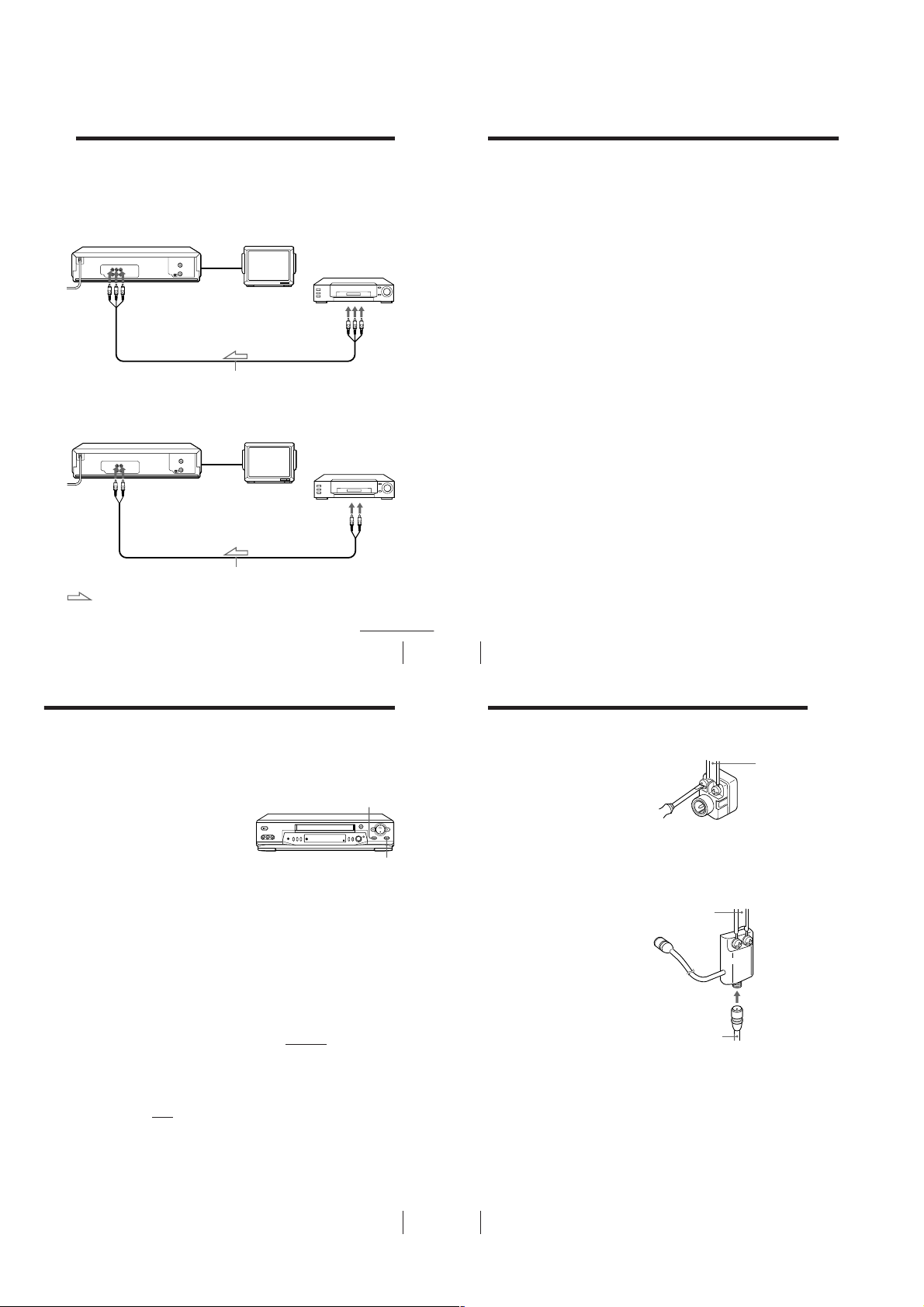
Editing with another VCR
Editing with another VCR (continued)
How to connect to record on this VCR
For SLV-EX90S AR and EX80S AR only
This VCR (Recorder)
LINE-1 IN
VMC-810HG audio/video cable (not supplied)
For SLV-EX50 AR only
This VCR (Recorder)
LINE-1 IN
VMC-710HG/720HG audio/video cable (not supplied)
: Signal flow
How to connect to a stereo system (SLV-EX90S AR/
EX80S AR only)
Connect the LINE-1 IN AUDIO R/L or LINE-2 IN AUDIO L/R jacks on this
VCR to the audio output jacks on the stereo system, using the RK-C510HG
TV
Other VCR (Player)
LINE OUT
TV
Other VCR (Player)
LINE OUT
continued
Additional Operations
57
58
audio cable (not supplied).
Tips
• (For SLV-EX50 AR only)
Use commercially available connecting cable such as the Sony VMC-710HG/720HG
(2-phono to 2-phono). If the other VCR has the AUDIO L and R jacks, use a
connecting cable such as the Sony VMC-910HG (3-phono to 2-phono).
• (For SLV-EX90S AR/EX80S AR only)
If the other VCR is a monaural type, the sound is recorded only on the channel
whose jack is connected to the audio plug. To record on both right and left channels,
connect the audio plugs to the AUDIO R/L jacks using a VMC-910HG (3-phono to
2-phono) audio/video cable (not supplied).
Notes
• Make sure you connect the plugs to jacks of the same color.
• (For SLV-EX90S AR/EX80S AR only)
When you connect a monaural VCR to the LINE-1 IN or LINE-2 IN jacks, make sure
to connect the audio plug to the AUDIO L (white) jack. The sound is recorded on
both right and left channels. When connecting to the AUDIO R (red) jack, the
sound is recorded only on the right channel.
• If you connected this VCR to both the LINE IN and LINE OUT jacks of the other
VCR, select the input correctly to prevent humming noise.
Additional Operations
Operation
(when recording on this VCR)
Before you start editing
• Turn on your TV and set it to the
video channel.
• Press INPUT SELECT or CH +/– to
display “L1” or “L2” (SLV-EX90S AR/
EX80S AR only) in the display
window.
• Press REC SPEED to select the tape
speed (SP or LP for the PAL-N system,
and SP or EP for the NTSC system).
1
Insert a source tape with its safety tab removed into the other
(playback) VCR. Search for the point to start playback and set it to
playback pause.
2
Insert a tape with its safety tab in place into this (recording) VCR.
Search for the point to start recording and press X PAUSE.
3
Press z REC on this VCR to set it to recording pause.
4
To start editing, press the X PAUSE buttons on both VCRs at the same
time.
To stop editing
Press the x STOP buttons on both VCRs.
Tips
• To edit more precisely, press the X PAUSE buttons on the VCRs to release pause.
• To cut out unwanted scenes while editing, press X PAUSE on this VCR when an
unwanted scene begins. When it ends, press X PAUSE again to resume recording.
Note
• If you start recording following the procedure above, the VCR won’t start recording
with the APC function. To record a tape with the APC function, press z REC again
during recording pause in step 3 so that the VCR analyzes the tape. Then, press
X PAUSE after the APC indicator stops flashing to start recording. If you press
X PAUSE before the APC indicator stops flashing, the APC function is canceled.
X PAUSE
z REC
Additional Information
General setup information
Attaching the external
antenna connector
When using a 300-ohm twin lead cable
for aVHF/UHF antenna, use the EAC-32
antenna connector (not supplied) to
connect the antenna to the VCR.
1 Loosen the screws on the antenna connector.
2 Wind the twin leads around the screws on the antenna connector.
3 Retighten the screws.
Attaching a UHF/VHF band
mixer
When using both a 75-ohm coaxial cable
and a 300-ohm twin lead cable for a
VHF/UHF antenna, use the EAC-66
UHF/VHF band separator/mixer (not
supplied) to connect the antenna to the
VCR.
1 Loosen the screws on the mixer.
2 Wind the twin leads around the screws on the mixer.
3 Retighten the screws.
4 Connect the 75-ohm coaxial cable to the mixer.
300-ohm twin
lead cable
75-ohm coaxial
cable
300-ohm twin
lead cable
EAC-32 antenna
connector (not
supplied)
EAC-66
UHF/VHF
band
separator/
mixer (not
supplied)
Additional Operations
59
– 1-14 –
Additional Information
60

Index to parts and controls
Refer to the pages indicated in parentheses ( ) for details.
Front panel
1
!•!ª
!¶
1 ?/1 POWER switch (13, 38)
2 Tape compartment
3 A EJECT button (26)
4 m REW (rewind) button (26, 46)
5 H PLAY button (26)
6 M FF (fast-forward) button
(26, 46)
7 z REC (record) button (29)
8 x STOP button (26)
9 X PAUSE button (26)
q; SEARCH MODE button/indicator
(40, 41, 42, 44, 45)
qa EASY TIMER knob (31, 40, 41, 42,
44, 45)
2
!§
!¡!™!£
qs CHANNEL/TRACKING +/–
buttons (29, 54)
qd Remote sensor (5)
qf SYNCHRO REC button (48)
(SLV-EX90S AR only)
qg REC SPEED SP (Standard Play)/LP
(Long Play)/EP (Extended Play)
button (29)
qh COLOR SYSTEM button (26)
qj ONE TOUCH TUNING button (16)
2
qk R
(Reality Regenerator) button (54)
(SLV-EX90S AR only)
ql LINE-2 IN VIDEO/AUDIO L/R
jacks (58) (SLV-EX90S AR/EX80S AR
only)
Index to parts and controls (continued)
Display window
STEREO
6
4
3
5
9
8!¢!∞ !º
7
1 Timer indicator (38)
2 STEREO indicator (52) (SLV-EX90S
AR/EX80S AR only)
3 Tape speed indicator (29)
4 VIDEO indicator (13, 30)
5 CLOCK indicator (33)
6 AM/PM indicator (33)
7 START indicator (31)
SP
LP
EP
STOPCLOCK START
NTSC
APCVIDEO AMPM
8 APC (Adaptive Picture Control)
indicator (55)
9 STOP indicator (32)
0 Tracking indicator (54)
qa Color system indicator (26)
qs Time counter/clock/line/channel
indicator (27, 29, 33, 59)
qd Tape/recording indicator (29)
PAL
Rear panel (SLV-EX90S AR/EX80S AR)
213
1 AC power cord
2 LINE-1 IN AUDIO R/L/VIDEO
jacks (57)
3 VHF/UHF IN/OUT connectors (9,
10, 11, 12)
4 RF (Radio Frequency) UNIT switch
5 LINE OUT AUDIO/VIDEO R/L
Rear panel (SLV-EX50 AR)
213
(13)
jacks (7)
Additional Information
45
continued
65
Additional Information
66
Index to parts and controls (continued)
Remote commander
TV/VIDEO
123
456
789
0
1
2 Z EJECT button (26)
3 TV/VIDEO button (for TV) (13, 30)
4 INPUT SELECT button (30, 38)
5 CLEAR button (27, 51)
6 EASY TIMER button (34)
7 R
8 z REC button (29, 47)
9 REC SPEED button (29)
0 ×2 button (46)
qa MENU button (10, 56)
qs Tape/menu operation buttons
remote control switch (5)
2
(Reality Regenerator) button (54)
(SLV-EX90S AR only)
X PAUSE/M button (26)
x STOP/m button (26)
m REW (rewind)/< button (26,
46)
M FF (fast-forward)/, button (26,
46)
H PLAY/OK button (26)
5
1 AC power cord
2 LINE-1 IN AUDIO/VIDEO jacks
(57)
3 VHF/UHF IN/OUT connectors (9,
10, 11, 12)
4
4 RF (Radio Frequency) UNIT switch
(13)
5 LINE OUT AUDIO/VIDEO jacks (8)
continued
Additional Information
67
– 1-15 –
Additional Information
68

123
456
789
0
qd ?/1 (power) switch (38)
qf AUDIO MONITOR button (52)
(This button doesn’t work for SLVEX50 AR only)
qg Number buttons and ENTER (AM/
PM) buttons (20, 30, 33)
qh CH (channel) +/– buttons (20, 29)
qj VOL (volume) +/– buttons (for TV)
qk DISPLAY button (27, 29)
ql ./> INDEX SEARCH buttons
(43)
w; y SLOW button (46)
Additional Information
69
– 1-16E –

SECTION 2
DISASSEMBLY
NOTE: Follow the disassembly procedure in the numerical order given.
2-1. CASE, FRONT PANEL BLOCK ASSEMBLY
1 Two tapping screws
4
Flat Cable FDI-002
3
Upper case
SLV-EX50/EX80S/EX90S
2
Two tapping screws
Hooks
Hooks
Front panel
7
(Engaged by the six hooks)
Hooks
Hooks
2-2. DM-98 BOARD, DI-81 BOARD, FJ-31 BOARD
7 Flat Cable FDI-002
6
FJ-31 board
Two screws
8
(B2.6 × 8)
9 Earth Plate
Flat Cable FDM-010
5
6
Flat Cable FDI-002
1 Four screws
(B2.6 × 8)
Two screws
0
(B2.6 × 8)
4 DI-81 board
2-1
3 Flat Cable FDM-010
Flat Cable FDI-002
5
2 DM-98 board
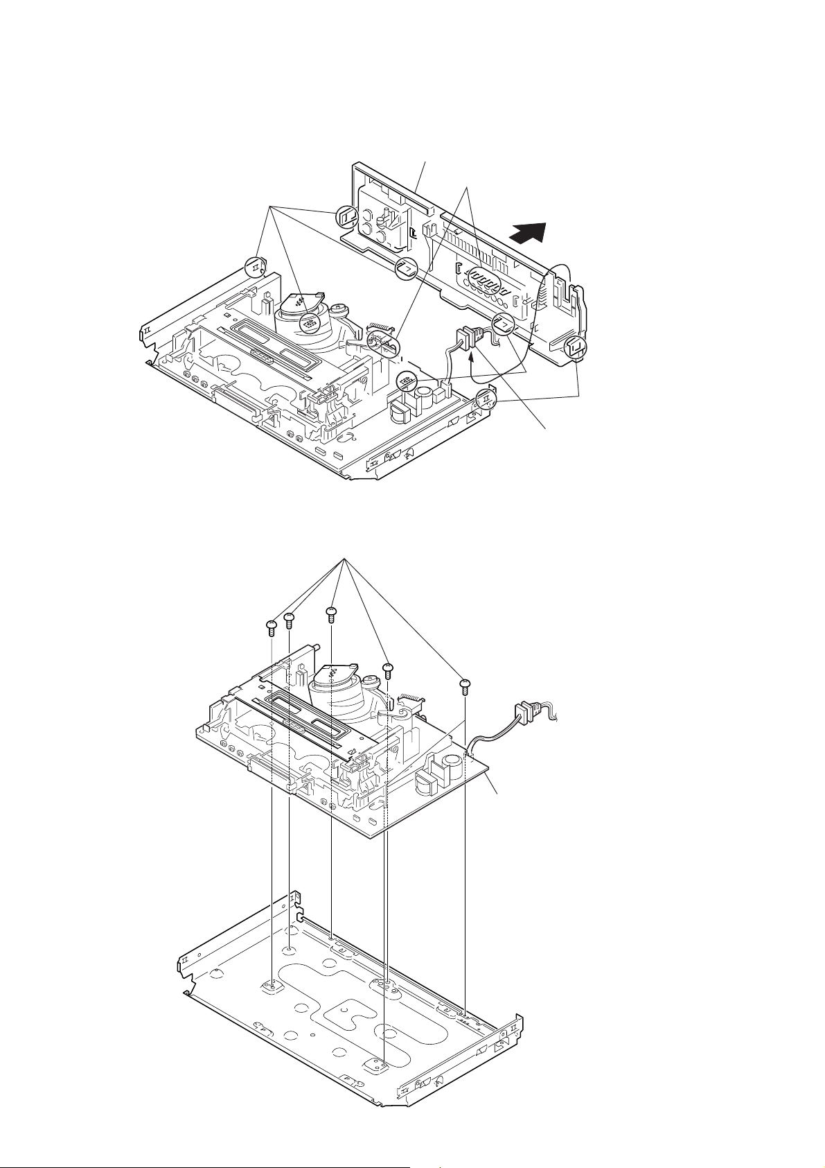
2-3. REAR PANEL
2-4. MA-402 BOARD
2 Rear panel
(Engaged by the seven hooks)
Hooks
Hooks
Hooks
Hooks
1 POWER code stopper
1 Six screws
(Sumitite (B3) +BV)
2 MA-402 board with
mechanism deck
2-2

qa MA-402 board
7 MD base (M)
8 MD base (R)
0 MD base (R)
6 Two screws
(BVTP 3 × 12)
9 Screw
(BVTP 3 × 12)
2 Screw
(Sumitite (B3), +BV)
qs Mechanism deck
1 Flexible cable
5 Harness FE-141
3 Flat Cable FAC-009
4 Flat cable FMD-022/FMD-023
CN202
CN331
Note: When mounting the mechanism deck,
first align mark on the rotary switch.
2-5. MECHANISM DECK
2-3
 Loading...