

Sony SLV-ED22, SLV-ED55, SLV-ED88, SLV-ED99 Service manual
SLV-ED22
/
ED55
/
ED88
/
ED99
RMT-V297/V297A/V297D/V299/V299C
SERVICE MANUAL
Photo: SLV-ED99KR
• Refer to the SERVICE MANUAL of VHS MECHANICAL
ADJUSTMENTS VI for MECHANICAL ADJUSTMENTS.
(9-921-647-11)
* The abbreviations of ED22/ED55/ED88 and ED99 contained in this
service manual are indicated when these models are common to all
their corresponding models as given below.
Abbreviated
model name
All model ED22KR
names ED22PL
SLV- ED22TW ED99TW
ED22 ED55 ED88 ED99
ED55KR
ED55PL
ED88TW ED99PL
ED99KR
Taiwan Model
SLV-ED22TW/ED88TW/ED99TW
K orea Model
SLV-ED22KR/ED55KR/ED99KR
Philippines Model
SLV-ED22PL/ED55PL/ED99PL
S MECHANISM
System
Format
VHS NTSC standard
Video recording system
Rotary head helical scanning FM system
Video heads
Double azimuth four heads (SLV-ED55/ED88/
ED99)
Double azimuth two heads (SLV-ED22)
Video signal
NTSC color , EIA standards
Tape speed
SLV-ED22: KR, PL/ED55/ED99: KR, PL
SP: 33.35 mm/s (1
EP: 11.11 mm/s (
LP: 16.67 mm/s (
playback only
SLV-ED22TW/ED88/ED99TW:
SP: 33.35 mm/s (1
EP: 11.11 mm/s (
Maximum recording/playback time
8 hrs. in EP mode (with T-160 tape)
Fast-forward and rewind time
Approx. 3 min. (with T-120 tape)
3
/ 8 inches/s)
7
/ 16 inches/s)
11
/ 16 inches/s),
3
/ 8 inches/s)
7
/ 16 inches/s)
SPECIFICATIONS
Tuner section
Channel coverage
VHF 2 to 13
UHF 14 to 69
CA TV A-8 to A-1, A to W, W+1 to W+84
(SLV-ED22: KR, PL/ED55/ED99: KR, PL)
CATV A-6 to A-1, A, B, C to W+1, W+12 to W+84
(SLV-ED22TW/ED88/ED99TW)
Antenna
75-ohm antenna terminal for VHF/UHF
Inputs and outputs
SLV-ED99:
LINE-1 IN and LINE-2 IN (SLV-ED99PL)
LINE-1 IN (SAT IN/STB IN), LINE-2 IN and
LINE-3 IN (SLV-ED99: KR, TW)
VIDEO IN, phono jack (1 each)
Input signal: 1 Vp-p, 75 ohms, unbalanced,
sync negative
AUDIO IN, phono jack (2 each)
Input level: 327 mVrms
Input impedance: more than 47 kilohms
– Continued on next page –
VIDEO CASSETTE RECORDER

LINE-1 OUT
VIDEO OUT, phono jack (1)
Output signal: 1 Vp-p, 75 ohms, unbalanced,
sync negative
AUDIO OUT, phono jack (2)
Standard output: 327 mVrms
Load impedance: 47 kilohms
Output impedance: less than 10 kilohms
LINE-2 OUT
AUDIO OUT, phono jack (2)
Standard output: 327 mVrms
Load impedance: 47 kilohms
Output impedance: less than 10 kilohms
SLV-ED88:
LINE-1 IN
VIDEO IN, phono jack (1)
Input signal: 1 Vp-p, 75 ohms, unbalanced,
sync negative
AUDIO IN, phono jack (2 each)
Input level: 327 mVrms
Input impedance: more than 47 kilohms
LINE-1 OUT
VIDEO OUT, phono jack (1)
Output signal: 1 Vp-p, 75 ohms, unbalanced,
sync negative
AUDIO OUT, phono jack (2)
Standard output: 327 mVrms
Load impedance: 47 kilohms
Output impedance: less than 10 kilohms
LINE-2 OUT
AUDIO OUT, phono jack (2)
Standard output: 327 mVrms
Load impedance: 47 kilohms
Output impedance: less than 10 kilohms
SLV-ED22/ED55:
LINE-1 IN
VIDEO IN, phono jack (1)
Input signal: 1 Vp-p, 75 ohms, unbalanced,
sync negative
AUDIO IN, phono jack (1)
Input level: 327 mVrms
Input impedance: more than 47 kilohms
LINE-2 IN (SLV-ED55)
VIDEO IN, phono jack (1)
Input signal: 1 Vp-p, 75 ohms, unbalanced,
sync negative
AUDIO IN (MONO), phono jack (2)
Input level: 327 mVrms
Input impedance: more than 47 kilohms
LINE-1 OUT
VIDEO OUT, phono jack (1)
Output signal: 1 Vp-p, 75 ohms, unbalanced,
sync negative
AUDIO OUT, phono jack (1)
Standard output: 327 mVrms
Load impedance: 47 kilohms
Output impedance: less than 10 kilohms
Timer section
Clock
Quartz locked
Timer indication
12-hour cycle
Timer setting
8 programs per month (max.)
Power back-up
Built-in self-charging capacitor
Back-up duration: up to 8 hours at a time
General
Power requirements
110 - 240 V AC, 50/60 Hz
(SLV-ED22PL/ED55PL/ED99PL)
100 V AC, 60 Hz
(SLV-ED22TW/ED88TW/ED99TW)
110 - 220 V AC, 60 Hz
(SLV-ED22KR/ED55KR/ED99KR)
Power consumption
21 W (SLV-ED99KR)
17 W (SLV-ED99PL)
15 W (SLV-ED22: KR, PL/ED55/ED88/ED99TW)
14 W (SLV-ED22TW)
Operating temperature
5°C to 40°C
Storage temperature
–20°C to 60°C
Dimensions
Approx. 430 × 97 × 288 mm (w/h/d)
including projecting parts and controls
Mass
Approx. 4.1 kg
Supplied accessories
Remote commander (1)
Size AA (R6) batteries (2)
75-ohm coaxial cable with F-type connectors (1)
Plug adaptor (1) (SLV-ED22PL/ED55PL/ED99PL)
Design and specifications are subject to change
without notice.
SAFETY CHECK-OUT
After correcting the original service problem, perform the following
safety checks before releasing the set to the customer :
1. Check the area of your repair for unsoldered or poorly-soldered connections. Check the entire board surface for solder
splashes and bridges.
2. Check the interboard wiring to ensure that no wires are
“pinched” or contact high-wattage resistors.
3. Look for unauthorized replacement parts, particularly transistors, that were installed during a previous repair. Point them
out to the customer and recommend their replacement.
SAFETY-RELATED COMPONENT WARNING!!
COMPONENTS IDENTIFIED BY MARK 0 OR DOTTED
LINE WITH MARK 0 ON THE SCHEMATIC DIA GRAMS
AND IN THE PARTS LIST ARE CRITICAL TO SAFE
OPERATION. REPLACE THESE COMPONENTS WITH
SONY PARTS WHOSE PART NUMBERS APPEAR AS
SHOWN IN THIS MANUAL OR IN SUPPLEMENTS PUBLISHED BY SONY.
4. Look for parts which, though functioning, show obvious signs
of deterioration. Point them out to the customer and recommend their replacement.
5. Check the B+ voltage to see it is at the values specified.
– 2 –

TABLE OF CONTENTS
Section Title Page Section Title Page
SERVICE NOTE ...................................................................... 4
5. INTERFACE, IC PIN FUNCTION DESCRIPTION
1. GENERAL
Getting Started .............................................................. 1-1
Basic Operations ........................................................... 1-5
Additional Operations.................................................... 1-8
Editing............................................................................ 1-12
Additional Information ................................................... 1-13
2. DISASSEMBLY
2-1. Upper Case Removal .................................................... 2-1
2-2. Rear Panel Removal ..................................................... 2-1
2-3. PSM17-501 Board Removal ......................................... 2-1
2-4. Front Panel Section Removal........................................ 2-1
2-5. Mechanism Deck Removal............................................ 2-2
2-6. MA-377 Board Removal................................................ 2-2
2-7. RF-048 Board Removal (ED22TW/ED88/ED99TW) .... 2-2
2-8. Internal Views ................................................................ 2-3
2-9. Circuit Boards Location................................................. 2-4
3. BLOCK DIAGRAMS
3-1. Overall Block Diagram ................................................... 3-1
3-2. Video Block Diagram..................................................... 3-3
3-3. Servo/System Control Block Diagram .......................... 3-5
3-4. Audio Block Diagram ..................................................... 3-7
3-5. Tuner Block Diagram ..................................................... 3-9
3-6. Mode Control Block Diagram ........................................ 3-11
3-7. Power Bloc k Diagram .................................................... 3-13
4. PRINTED WIRING BOARDS AND
SCHEMATIC DIAGRAMS
4-1. Frame Schematic Diagr a m............................................ 4-3
4-2. Printed Wiring Boards and Schematic Diagrams ......... 4-5
MA-377 Printed Wiring Board ....................................... 4-5
MA-377 (Video, Audio) Schematic Diagram ................. 4-9
MA-377 (System Control) Schematic Diagram ............ 4-13
MA-377 (Servo Control) Schematic Diagram ............... 4-15
MA-377 (Hi-Fi Audio) Schematic Diagram.................... 4-17
MA-377 (Tuner) Schematic Diagram ............................ 4-19
MA-377 (I/O) Schematic Diagram................................. 4-21
MA-377 (Mode Control) Schematic Diagram................ 4-23
GK-12 Printed Wiring Board and
Schematic Diagram....................................................... 4-25
RF-048 Printed Wiring Board and
Schematic Diagram....................................................... 4-27
FJ-26, MF-321 Printed Wiring Boards and
Schematic Diagrams ..................................................... 4-29
DS-92, KK-24 Printed Wiring Boards and
Schematic Diagrams ..................................................... 4-31
PSM17-501 Printed Wiring Board................................. 4-33
PSM17-501 Schematic Diagram................................... 4-35
5-1. System Control-Video Block Interface
(MA-377 BOARD IC101)............................................... 5-1
5-2. System Control-Servo Peripheral Circuit Interface
(MA-377 BOARD IC101)............................................... 5-1
5-3. System Control-Mechanism Block Interface
(MA-377 BOARD IC101)............................................... 5-2
5-4. System Control-Audio Block Interface
(MA-377 BOARD IC101)............................................... 5-3
5-5. Servo/System Control,
OSD Microprocessor Pin Function
(MA-377 BOARD IC101)............................................... 5-4
5-6. ZWEITON Processor Pin Function
(GK-12 BOARD IC001) ................................................. 5-5
6. ERROR CODES ....................................................... 6-1
7. ADJUSTMENTS
7-1. Mechanical Adjustments............................................... 7-1
7-2. Electrical Adjustments................................................... 7-1
2-1. Pre-Adjustment Preparations........................................ 7-1
2-1-1. Instruments to be Used............................................ 7-1
2-1-2. Connection ............................................................... 7-1
2-1-3. Set-up of Adjustment ............................................... 7-1
2-1-4. Alignment T apes....................................................... 7-1
2-1-5. Specified I/O Level and Impedance
Input/Output terminal ............................................... 7-1
2-1-6. Adjusting Sequence ................................................. 7-2
2-2. Power Supply Adjustment ............................................. 7-2
2-2-1. Power Supply Check ................................................ 7-2
2-3. Servo System Adjustment............................................. 7-2
2-3-1. RF Switching Position Adjustment........................... 7-2
2-4. Audio System Adjustments........................................... 7-3
2-4-1. Hi-Fi Audio System Adjustment ............................... 7-3
1. AF Switching Position Adjustment ........................... 7-3
2. Frequency Response Check.................................... 7-3
3. Overall Level Characteristic and
Distortion Factor Check ........................................... 7-4
4. Overall S/N Check.................................................... 7-4
2-4-2. Normal Audio System Adjustment........................... 7-4
1. ACE Head Adjustment ............................................. 7-4
2. E-E Output Level Check........................................... 7-4
3. Frequency Response Check.................................... 7-4
4. Overall Level Characteristic and Distortion
Factor Check ............................................................ 7-5
5. Overall S/N Check.................................................... 7-5
2-5. Tuner System Adjustment ............................................. 7-5
2-5-1. Separation Adjustment............................................. 7-5
2-6. Parts Arrangement Diagram for Adjustments............... 7-6
8. REPAIR PARTS LIST
8-1. Exploded Vie ws............................................................. 8-1
8-1-1. Front Panel and Cabinet Assemblies....................... 8-1
8-1-2. Chassis Assembly.................................................... 8-2
8-1-3. Mechanism Chassis Assembly (1)........................... 8-3
8-1-4. Mechanism Chassis Assembly (2)........................... 8-4
8-1-5. Mechanism Chassis Assembly (3)........................... 8-5
8-2. Electrical Parts List ....................................................... 8-6
– 3 –
SERVICE NOTE
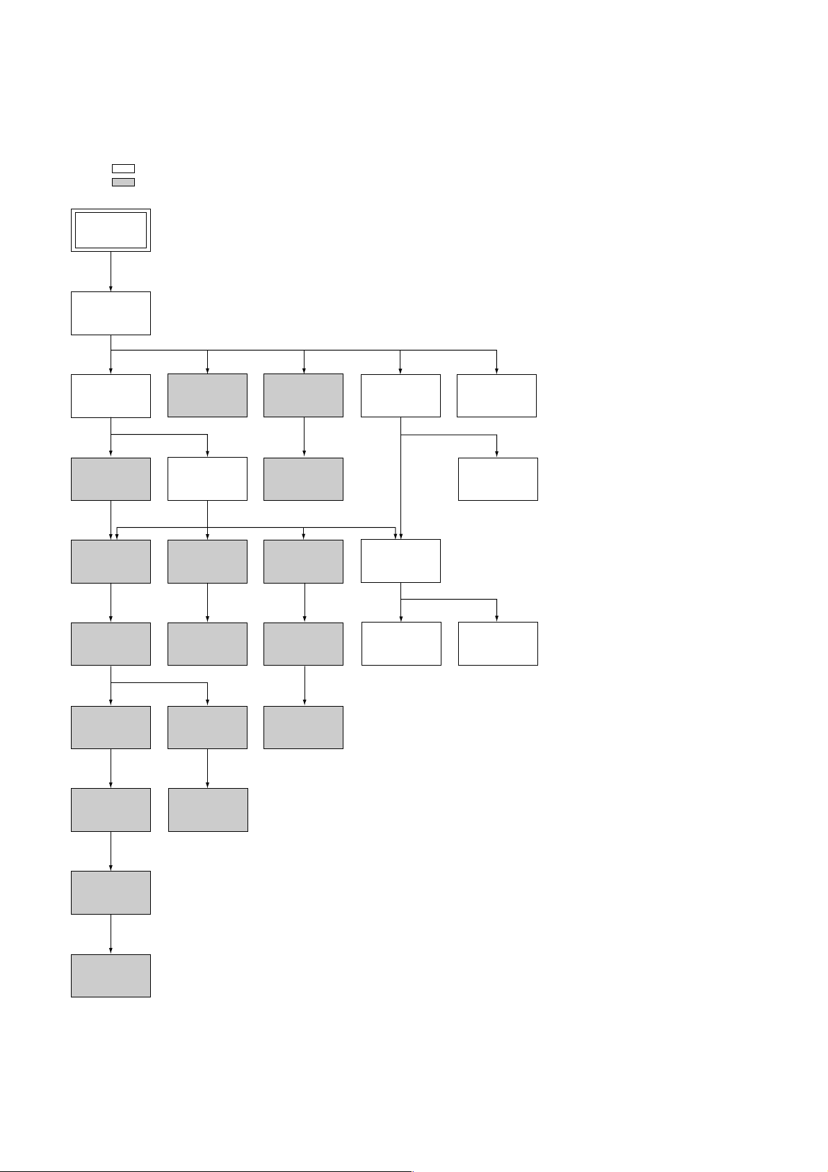
1. DISASSEMBLY
• This set can be disassembled in the order shown below.
Note: Pages in indicated pages in the SERVICE MANUAL.
Pages in indicated pages in the VHS MECHANICAL ADJUSTMENT MANUAL VI.
Set
Upper case
(Page 2-1)
Front Panel
Section
(Page 2-1)
FL Complete
Ass’y
(Page 13)
Retainer
Plate
(Page 22)
FL Slider
Block Ass’y
(Page 22)
Cam Gear
(Page 23)
Pinch Press
Block Ass’y
(Page 14)
Mechanism
Deck
(Page 2-2)
Rubber
Belt
(Page 15)
Capstan
Motor
(Page 15)
Cam Motor
Retainer
(Page 31)
Ground Shaft
Ass’y
(Page 13)
Drum
Ass’y
(Page 13)
Rubber
Belt
(Page 15)
Pully Gear
Ass’y
(Page 29)
Reel Direct
Ass’y
(Page 30)
Rear
Panel
(Page 2-1)
MA-377
Board
(Page 2-2)
Rotary
Switch
(Page 2-2)
RF-048
Board
(Page 2-2)
PSM17-501
Board
(Page 2-1)
Tuner
Unit
Rubber
Belt
(Page 15)
Slider
(Page 26)
Loading
Gear (T, S)
(Page 28)
Cam Motor
(Page 31)
– 4 –
Getting Started
5
Getting Started
Getting Started
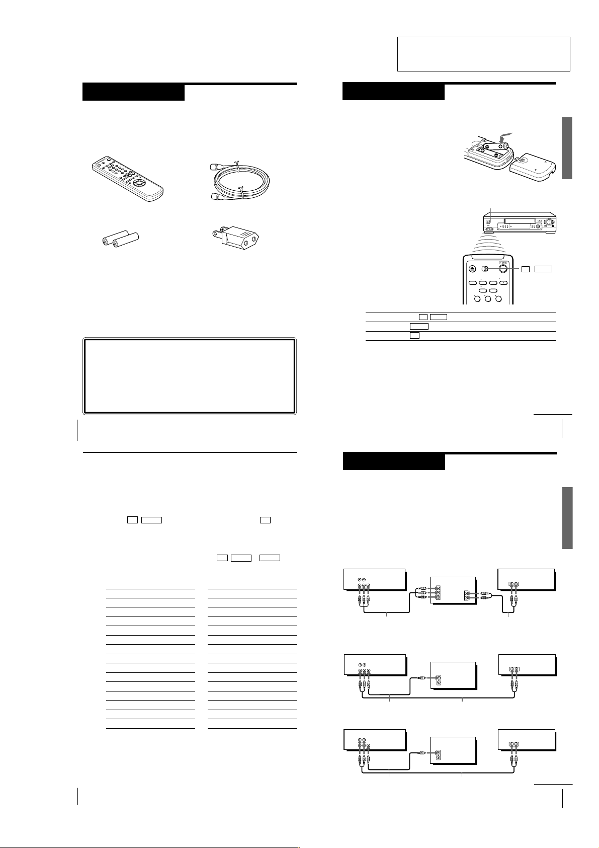
Inserting the batteries
Insert two size AA (R6) batteries by
matching the + and – on the batteries
to the diagram inside the battery
compartment.
Insert the negative (–) end first, then
push in and down until the positive
(+) end clicks into position.
Using the remote commander
You can use this remote
commander to operate this VCR
and a Sony TV. Buttons on the
remote commander marked with
a dot (•) can be used to operate
your Sony TV. If the TV does not
have the g symbol near the
remote sensor, this remote
commander will not operate the
TV.
Step 2
Setting up the remote commander
To operate
the VCR
a Sony TV
Set TV / VIDEO to
VIDEO and point at the remote sensor on the VCR
TV and point at the remote sensor on the TV
Remote sensor
TV / VIDEO
Notes
• With normal use, the batteries should last about three to six months.
• If you do not use the remote commander for an extended period of time, remove
the batteries to avoid possible damage from battery leakage.
• Do not use a new battery with an old one.
• Do not use different types of batteries.
123
continued
Step 1
Unpacking
Check that you have received the following items with the VCR:
• Remote commander
• 75-ohm coaxial cable with F-type
connectors
SECTION 1
GENERAL
SLV-ED22/ED55/ED88/ED99
This section is extracted from SLVED22KR/ED55KR/ED99KR instruction
manual. (3-058-932-11)
• Size AA (R6) batteries
• Plug adaptor
Checking your model name
The instructions in this manual are for the 3 models: SLV-ED99PL,
ED55PL and ED22PL. Check your model number by looking at the
rear panel of your VCR. SLV-ED99PL is the model used for illustration
purpose. Any difference in operation is clearly indicated in the text,
for example,“SLV-ED22PL only.”
Getting Started
4
Step 2: Setting up the remote commander (continued)
Controlling other TVs with the remote commander
(SLV-ED99PL only)
6
The remote commander is preprogrammed to control non-Sony TVs. If your
TV is listed in the table below, set the appropriate manufacturer ’s code
number.
1
Set TV / VIDEO at the top of the remote commander to TV .
2
Hold ?/1 down, and enter your TV’s code number(s) using the number
buttons. Then release ?/1.
Now you can use the ?/1, VOL +/–, CH +/– and TV/VIDEO buttons to
control your TV. You can also use the buttons marked with a dot (•) to
control a Sony TV. To control the VCR, reset TV / VIDEO to VIDEO .
Code numbers of controllable TVs
If more than one code number is listed, try entering them one at a time until
you find the one that works with your TV.
Manufacturer
Sony
Akai
AOC
Centurion
Colonad
Curis-Mathes
Emerson
Fisher
General Electric
Gold Star
Hitachi
JVC
Magnavoc
Marantz
Notes
• If the TV uses a different remote control system from the one programmed to work
with the VCR, you cannot control your TV with the remote commander.
• You may not be able to use some buttons to control non-Sony TVs due to the remote
commander’s signal limitations.
• If you enter a new code number, the code number previously entered will be erased.
• When you replace the batteries of the remote commander, the code number may
automatically reset to 01 (Sony). If your TV is not a Sony, it is recommended to
Getting Started
manually set the appropriate code number every time you replace the batteries.
Code number
01
04
04
12
03
12
03, 04, 14
11
06, 10
03, 04, 17
02
09
08
13
Manufacturer
MGA/Mitsubishi
Panasonic
Philips
Pioneer
Quasar
Radio Shack
RCA
Sanyo
Sears
Sharp
Sylvania
Teknika
Toshiba
Zenith
Code number
13
06, 19
08
16
06
05, 14
10
11
07, 11
05, 18
08
14
07
15
Step 3
Hookup
Audio/video (A/V) hookup
If your TV has audio/video (A/V) input jacks, you will get a better picture
and sound when you hook up your VCR using these connections. If your TV
doesn’t have A/V inputs, see the following page for antenna hookup.
For SLV-ED99PL only
For a true “home theater” experience, you should connect the audio outputs
of your VCR or TV to your stereo system.
A Use this hookup if your TV has stereo jacks
VCR Stereo receiver
AUDIO VIDEO
LINE-2
OUT
LINE-1
OUT
Audio/video cable (not supplied)
B Use this hookup if your TV doesn’t have stereo jacks
VCR Stereo receiver
AUDIO VIDEO
LINE-2
OUT
LINE-1
OUT
Video cable (not supplied)
VCR Stereo receiver
AUDIO VIDEO
LINE-2
OUT
LINE-1
OUT
Video cable (not supplied)
TV
IN
VIDEO
AUDIO OUT
AUDIO
Audio cable (not supplied)
TV
IN
VIDEO
AUDIO
Audio cable (not supplied)
or
TV
IN
VIDEO
AUDIO
Audio cable (not supplied)
AUX IN
AUX IN
AUX IN
Getting Started
Getting Started
continued
7
1-1
Step 3: Hookup (continued)
11
Getting Started
Getting Started
PLAY
OK
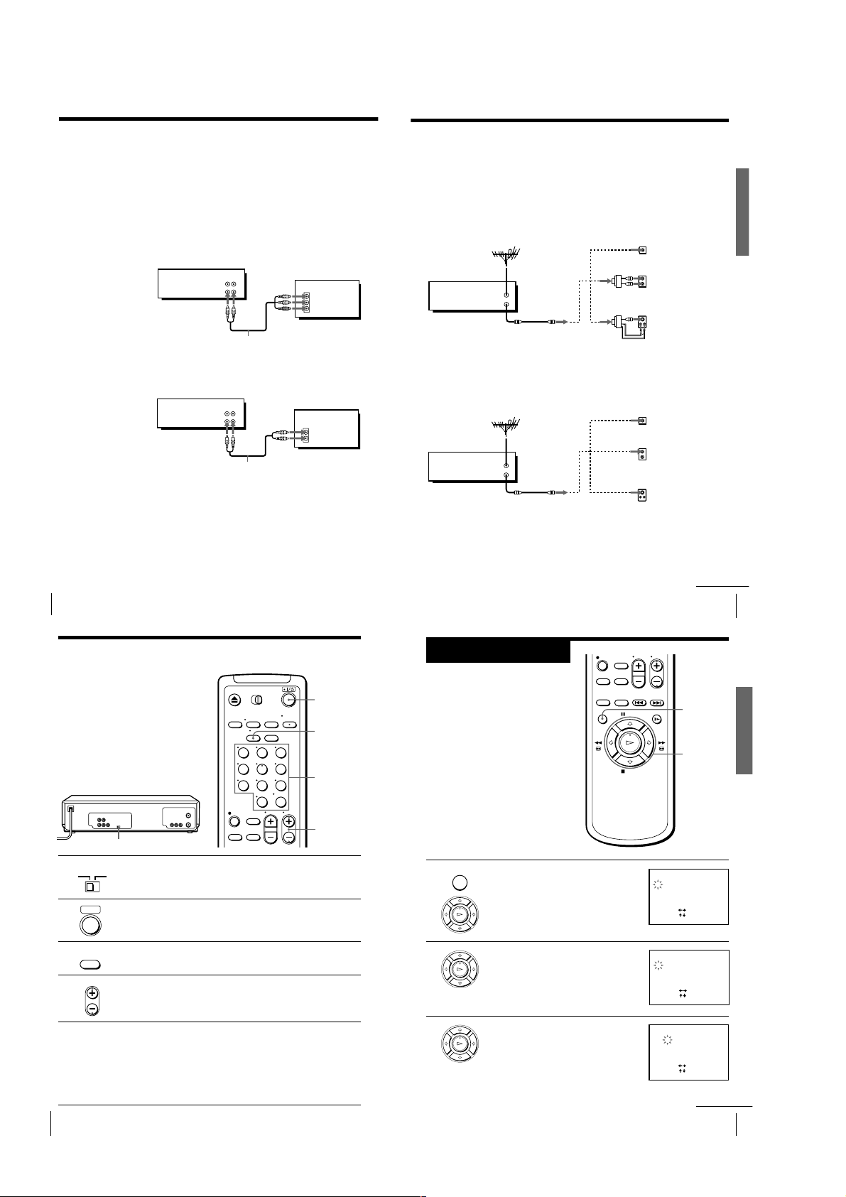
1 Press MENU, then press M/m to move the
cursor (B) to CLOCK SET, then press OK.
2 Press M/m to set the month.
3 Press , to flash the day and press M/m
to set the day.
The day of the week is set automatically.
Step 4
Setting the clock
You must set the time and date on the
VCR to be able to use the timer
recording features properly.
Before you start...
• Turn on the VCR and the TV.
• Set the TV to the VCR channel
(channel 3 or 4). If your TV is
connected to the VCR using A/V
connections, set the TV to video input.
• Press TV/VIDEO to display the
VIDEO indicator in the VCR’s display
window.
MENU
OK
M/m/</,
MENU
PLAY
OK
CLOCK SET
1 1/2000
SAT12:00
AM
SET
SELECT
:
[
]
END
:
[ OK ]
:
[]
PLAY
OK
CLOCK SET
11/1 /2000
THU12:00
AM
6
SET
SELECT
:
[
]
END
:
[ OK ]
:
[]
continued
Notes
• To listen to playback sounds in stereo, you must use the A/V connection.
• If you use the Trinitron TV Synchro Play function (see page 22), the A/V connection
is necessary. (If your TV has two or more inputs, connect the audio/video cable to
the VIDEO IN 1 jacks.)
• You can improve sound quality by connecting a stereo system to LINE-2 OUT jacks
using audio cable (not supplied).
For SLV-ED55PL and ED22PL only
A Use this hookup if your TV has stereo jacks
VCR
AUDIO VIDEO
LINE-1 IN
LINE-1 OUT
Audio/video cable (not supplied)
Antenna hookup
Make the following connections when you’re using an antenna.
A Use this hookup if you’re using:
• VHF/UHF antenna (you get channels 2–13 and channels 14 and higher)
• UHF-only antenna (you get channels 14 and higher)
• Separate VHF and UHF antennas
Rear of TV
VHF/UHF
A
Match the type of
VHF
UHF
VHF
B
C
connector on your
TV: A, B, or C.
TV
IN
VIDEO
AUDIO
VCR
VHF/UHF
IN
OUT
or
or
UHF
Getting Started
B Use this hookup if your TV doesn’t have stereo jacks
VCR
LINE-1 IN
LINE-1 OUT
Audio/video cable (not supplied)
Note
• If you use the Trinitron TV Synchro Play function (see page 22), the A/V connection
is necessary. (If your TV has two or more inputs, connect the audio/video cable to
the VIDEO IN 1 jacks.)
Getting Started
8
Step 3: Hookup (continued)
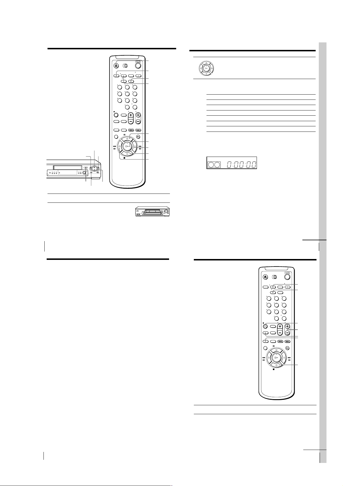
Setting the RF unit
When connecting the VCR to the TV
using only the antenna cable, you must
set the RF UNIT switch on the rear of the
VCR so that the TV can receive the
correct signal from the VCR.
If you made A/V connections (pages 7
or 8) you can skip this step.
1 Set the RF UNIT switch on the rear of the VCR to CH3 or CH4,
2 Press ?/1 (power) to turn on the VCR.
3 Press TV/VIDEO on the remote commander to turn on the VIDEO
4 Press CH +/– to display a channel number in the display window.
5 Turn on your TV and set it to the channel you selected in step 1
Getting Started
10
RF UNIT
RF UNIT
CH3
CH4
whichever channel is not used in your area. If both are used, set the
switch to either channel.
• ]/1
• TV/
VIDEO
indicator in the VCR’s display window.
• CH
Select an active channel number in your area.
(channel 3 or 4).
The channel you selected in step 4 appears on the TV screen. If the
channels change when you press CH +/–, you have made the
correct setting.
Whenever you use the VCR, set the TV to the channel selected in
step 1.
AUDIO VIDEO
123
456
789
0
IN
TV
VIDEO
AUDIO
?/1
TV/VIDEO
Number
buttons,
ENTER
CH +/–
B Use this hookup if you’re using a VHF-only antenna (you get
channels 2–13 only)
Rear of TV
VHF/UHF
Match the type of
A
VCR
VHF/UHF
or
IN
OUT
or
VHF
UHF
VHF
B
C
connector on your
TV: A, B, or C.
For connector
types B and C, no
UHF connection is
required.
UHF
If you cannot connect your antenna cable to the VCR directly
If your antenna cable is a flat cable (300-ohm twin lead cable), attach an external
antenna connector (not supplied) so you can connect the cable to the VHF/UHF IN
connector. If you have separate cables for VHF and UHF antennas, you should use a
U/V band mixer (not supplied). For details, see page 52.
continued
Getting Started
CLOCK SET
11/1/2000
WED12:00
[]
:
SELECT
[
:
]
SET
[ OK ]
:
END
9
AM
1-2
Step 4: Setting the clock (continued)
13
Getting Started
Getting Started
SP
APC
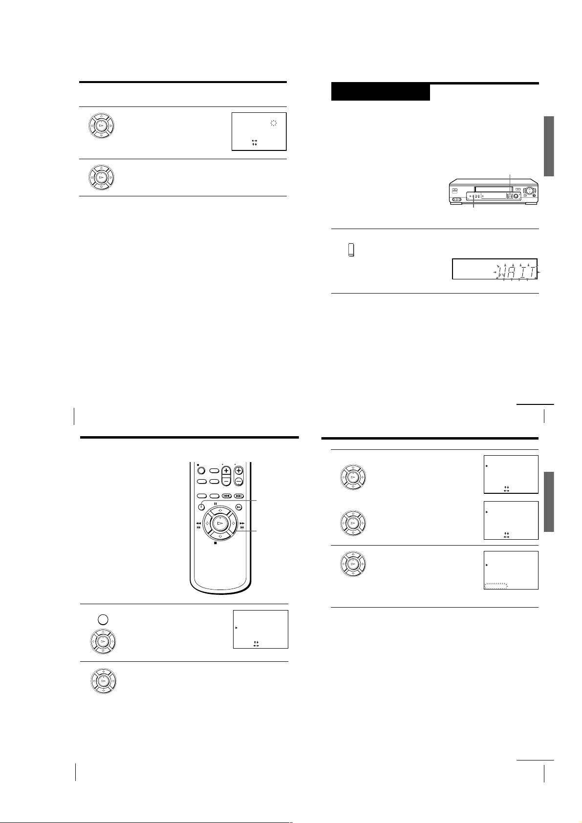
Step 5
Press and hold ONE TOUCH TUNING on the VCR for more than
three seconds.
The VCR starts presetting the channels.
The WAIT indicator goes off when all receivable channels are preset.
To check if the channels are preset correctly
Set the TV to the video channel and press CHANNEL +/– on the VCR.
If the TV screen changes to a different program each time you press
CHANNEL +/–, the channels are preset correctly.
Tip
• To stop the One Touch Tuning function, press ONE TOUCH TUNING or p STOP
on the VCR during the setting.
ONE TOUCH
TUNING
Presetting channels
First, we recommend that you preset the receivable channels in your area
using the One Touch Tuning function or the AUTO PRESET in the TUNER
PRESET menu. Then, if some channels could not be preset automatically, set
them manually; if there are any unwanted channels among the preset ones,
you can disable the channels.
Presetting all receivable
channels using the One
Touch Tuning function
CHANNEL +/–
ONE TOUCH
TUNING
continued
15
Getting Started
Getting Started
3
• To preset cable TV channels:
Press </, to set ANTENNA/CABLE
to CABLE.
• To preset VHF and UHF channels:
Press </, to set ANTENNA/CABLE
to ANT.
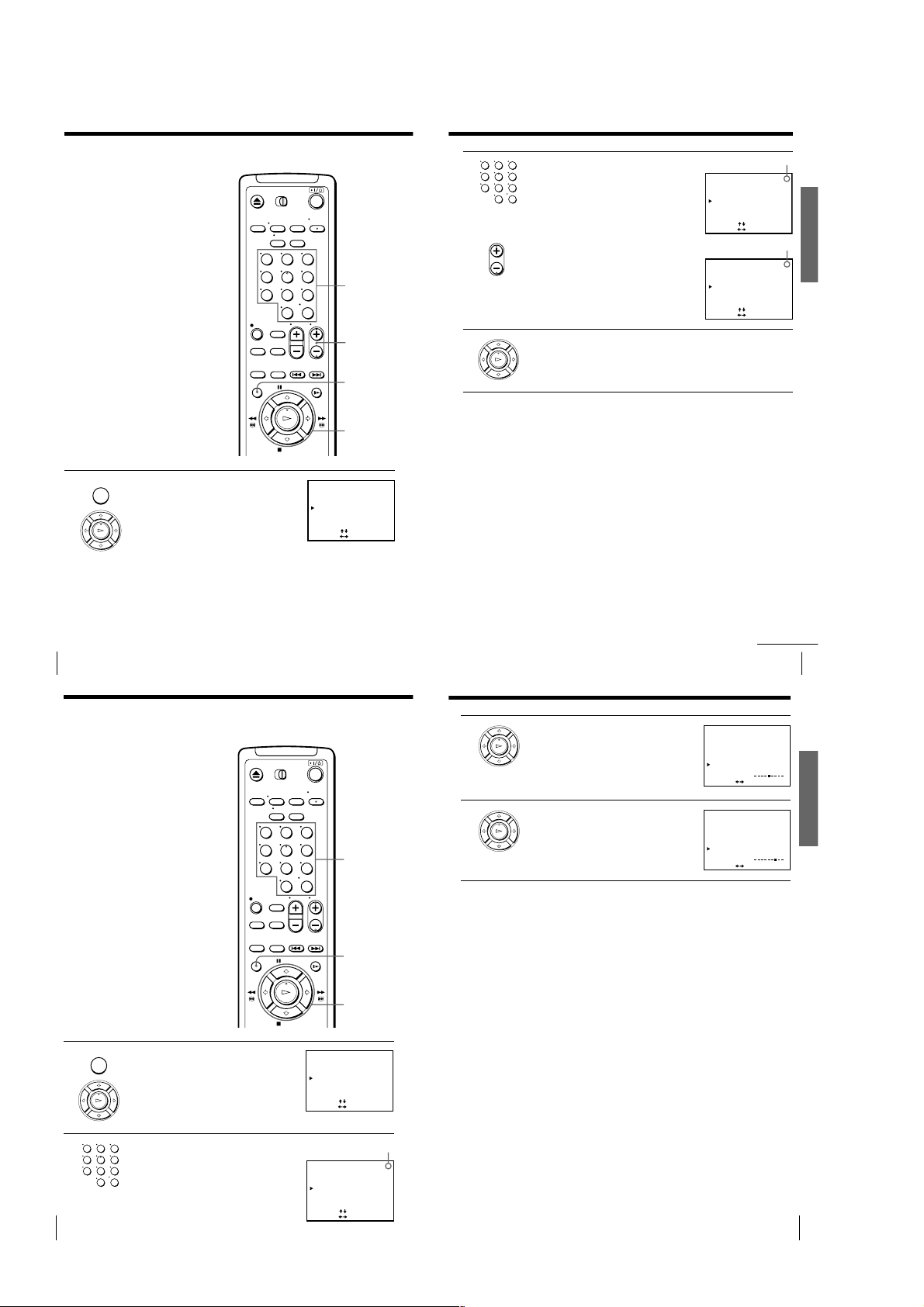
4
Press M/m to move the cursor (B) to
AUTO PRESET, then press OK.
All receivable channels are preset in
numerical sequence. When no more
receivable channels can be found,
presetting stops and the picture from the
lowest numbered channel is displayed on
the TV screen.
TUNER PRESET 2
CH
ANTENNA / CABLE
AUTO PRESET
MANUAL SET
AFT
ANT
ADD
ON
•
•
•
CABLE
ERASE
OFF
PLEASE WAIT
FINE TUNING
PLAY
OK
PLAY
OK
PLAY
OK
continued
4
5
Set the year, hour and minutes in
sequence, using / to flash the item to be
PLAY
OK
set, and >/. to select the digits.
Press OK to start the clock.
PLAY
OK
Tip
• To change the digits during setting, press < to return to the item to be changed,
and select the digits using >/..
Note
• The menu disappears automatically if you don’t proceed for more than a few
minutes.
CLOCK SET
11/1 /2000
SELECT
SET
END
[]
:
[
:
[ OK ]
:
]
THU 12
AM
:306
Getting Started
12
Step 5: Presetting channels (continued)
Presetting all receivable
channels automatically
Before you start…
• Turn on the VCR and the TV.
• Set the TV to the VCR channel
(channel 3 or 4). If your TV is
connected to the VCR using A/V
connections, set the TV to video input.
• Press TV/VIDEO to display the
VIDEO indicator in the VCR’s display
window.
1
2
MENU
PLAY
OK
PLAY
OK
Press MENU, then press M/m to move the
cursor (B) to TUNER PRESET, then press
OK.
Press M/m to select ANTENNA/CABLE.
TUNER PRESET
ANTENNA / CABLE
AUTO PRESET
MANUAL SET
AFT
FINE TUNING
[]
:
SELECT
[
:
SET
MENU
OK
M/m/</,
ANT
CABLE
•
ADD
ERASE
•
ON
OFF
•
]
TUNER PRESET
ANTENNA / CABLE
AUTO PRESET
MANUAL SET
AFT
FINE TUNING
[]
:
SELECT
[
:
SET
TUNER PRESET 2
ANTENNA / CABLE
AUTO PRESET
MANUAL SET
AFT
FINE TUNING
[]
:
SELECT
[
:
SET
1CH
1CH
ANT
•
CABLE
ADD
ERASE
•
ON
OFF
•
]
CH
ANT
•
CABLE
ADD
ERASE
•
ON
OFF
•
]
Getting Started14
1-3
Step 5: Presetting channels (continued)
17
Getting Started
Getting Started
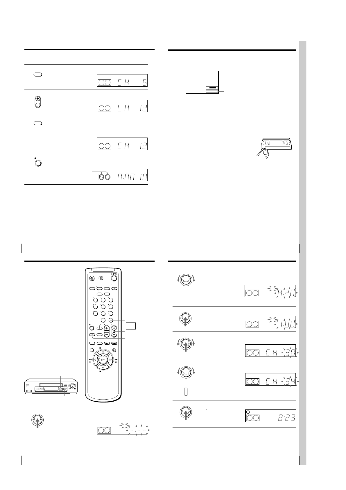
2 • To preset a channel:
1 Press the number buttons to enter the
channel number, then press ENTER.
2 Press </, to set MANUAL SET to
ADD.
• To disable a channel:
1 Press CH +/– to select the channel
number.
2 Press </, to set MANUAL SET to
ERASE.
3 Repeat step 2 to preset or disable channels as required, then press
OK.
123
456
789
0
Channel to be preset
Channel to be disabled
PLAY
OK
• CH
continued
19
Getting Started
Getting Started
3
Press M/m to select FINE TUNING.
The fine tuning meter appears.
4
Press </, to adjust to a clearer picture,
then press OK.
Note that the AFT setting switches to OFF.
Tip
• To select the channel in step 2 above, you can also use the CH +/– buttons. In this
case, you don’t need to press ENTER.
Notes
• The menu disappears automatically if you don’t proceed for more than a few
minutes.
• When adjusting FINE TUNING, the menu may become difficult to read due to
interference from the picture being received.
PLAY
OK
PLAY
OK
Presetting/disabling
channels manually
123
456
789
MENU
1 Press MENU, then press M/m to move the
cursor (B) to TUNER PRESET, then press
OK.
PLAY
OK
TUNER PRESET
ANTENNA / CABLE
AUTO PRESET
MANUAL SET
AFT
FINE TUNING
[]
:
SELECT
[
:
SET
TUNER PRESET
ANTENNA / CABLE
Number
buttons,
0
ENTER
AUTO PRESET
MANUAL SET
AFT
FINE TUNING
SELECT
SET
[]
:
[
:
5CH
ANT
•
CABLE
ADD
•
ERASE
ON
OFF
•
]
5CH
ANT
•
CABLE
ADD
ERASE
•
ON
OFF
•
]
CH +/–
MENU
OK
M/m/</,
TUNER PRESET
ANTENNA / CABLE
AUTO PRESET
MANUAL SET
AFT
FINE TUNING
:
SELECT
:
SET
[]
[
1CH
ANT
CABLE
•
ADD
ERASE
•
ON
OFF
•
]
Getting Started
16
Step 5: Presetting channels (continued)
If the picture is not clear
Normally, the Auto Fine Tuning (AFT)
function automatically tunes in channels
clearly. If, however, the picture of a
channel is not clear, you can also use the
manual tuning function.
MENU
1 Press MENU, then press M/m to move the
cursor (B) to TUNER PRESET, then press
OK.
PLAY
OK
123
456
789
0
TUNER PRESET
ANTENNA / CABLE
AUTO PRESET
MANUAL SET
AFT
FINE TUNING
SELECT
SET
Number
buttons,
ENTER
MENU
OK
M/m/</,
ANT
•
ADD
•
ON
•
[]
:
[
:
]
CABLE
ERASE
OFF
TUNER PRESET
ANTENNA / CABLE
AUTO PRESET
MANUAL SET
AFT
FINE TUNING
[
:
SET
TUNER PRESET
ANTENNA / CABLE
AUTO PRESET
MANUAL SET
AFT
FINE TUNING
[
:
SET
1CH
5CH
ANT
•
CABLE
ADD
•
ERASE
ON
•
OFF
]
5CH
ANT
•
CABLE
ADD
•
ERASE
ON
•
OFF
]
2 Press the number buttons to select the
123
channel you want to fine-tune, then press
456
ENTER.
789
0
Getting Started18
Selected channel
TUNER PRESET
ANTENNA / CABLE
AUTO PRESET
MANUAL SET
AFT
FINE TUNING
SELECT
SET
[]
:
[
:
CH
5
ANT
•
CABLE
ADD
•
ERASE
ON
OFF
•
]
1-4
Basic Operations
23
Basic Operations
Basic Operations
Recording TV
programs
1 Turn on your TV and set it to the video channel.
2 Insert a tape with its safety tab in place.
z REC
x STOP
DISPLAY
INPUT SELECT
CH +/–
TV/VIDEO
SP/EP
123
456
789
0
continued
Playing a tape
123
456
789
0
H PLAY
X PAUSE
M # FF
x STOP
m 3 REW
A EJECT
1 Turn on your TV and set it to the video channel.
2 Insert a tape.
The VCR turns on and starts playing
automatically if you insert a tape with its
safety tab removed.
Z EJECT
TRINITRON TV
SYNCHRO PLAY
CLEAR
DISPLAY
X PAUSE
H PLAY
M # FF
x STOP
m 3 REW
3
Press H PLAY.
PLAY
When the tape reaches the end, it will rewind automatically.
OK
Additional tasks
To
Stop play
Pause play
Resume play after pause
Fast-forward the tape
Rewind the tape
Eject the tape
To use the time counter
At the point on the tape that you want to find later, press CLEAR. The
counter in the display window resets to “0:00:00.” Search for the point
afterwards by referring to the counter.
VIDEO
EP
To display the counter on the TV screen, press DISPLAY.
Notes
• Tapes recorded in the LP mode on other VCRs can be played back on this VCR but
the picture quality cannot be guaranteed.
• While setting the menu on the TV screen, you cannot use the H PLAY, X PAUSE,
M # FF, m 3 REW, or x STOP buttons.
• The counter resets to “0:00:00” whenever a tape is reinserted.
• The counter stops counting when it comes to a portion with no recording.
Press
x STOP
X PAUSE
X PAUSE or H PLAY
M # FF during stop
m 3 REW during stop
Z EJECT
APC
Basic Operations
20
Basic Operations
Playing a tape (continued)
Turning on the VCR and TV, and starting playback
automatically (Trinitron TV Synchro Play)
You can only use this function if your TV is made by Sony (Trinitron TV).
How to connect to use this function
Connect the VCR and TV with the audio/video cable (see “Audio/video
(A/V) hookup” on page 7 or 8.) Be sure to connect the audio/video cable to
the VIDEO IN 1 jacks on the TV if the TV has two inputs or more. The TV
must be placed where it will respond to the remote commander while you
are pointing it at the VCR.
Operation
Make sure that the TV’s main power is on.
Press TRINITRON TV SYNCHRO PLAY and hold the remote commander in
place for about two seconds.
The VCR and TV turn on, and the TV is set to VCR reception. If there is a
tape in the VCR, playback starts automatically.
Notes
• If the Trinitron TV Synchro Play function does not work properly:
• Do not press TRINITRON TV SYNCHRO PLAY while playing back a video tape. If
– Wait a few moments, and press the button again.
– Replace both of the batteries with new ones, and press the button again.
Note that this function may not operate some Sony TVs because of the remote
commander’s signal limitations.
you do so, the TV’s input source will momentarily switch to the TV’s tuner.
continued
Basic Operations
21
Basic Operations
22
1-5
Recording TV programs (continued)
25
Basic Operations
Basic Operations
To check the remaining tape length
Press DISPLAY. The white bar indicates the approximate length of tape
remaining.
To watch another TV program while recording
1
Press TV/VIDEO to turn off the VIDEO indicator in the display
window.
2
If the TV is connected to the VCR’s LINE-1 OUT jacks, set the TV to TV
input; if not, skip this step.
3
Select another channel on the TV.
To save a recording
To prevent accidental erasure, break off the
safety tab as illustrated. To record on the tape
again, cover the tab hole with adhesive tape.
Safety tab
Tips
• To select a channel, you can use the number buttons on the remote commander.
Enter the channel number, then press ENTER.
• (SLV-ED99PL and ED55PL)
You can select a video source from the LINE-1 IN or LINE-2 IN jacks using INPUT
SELECT or CH +/– buttons.
• (SLV-ED22PL)
You can select a video source from the LINE-1 IN jack using INPUT SELECT or CH
+/– buttons.
• The display appears on the TV screen indicating information about the tape, but the
information won’t be recorded on the tape.
• If you don’t want to watch TV while recording, you can turn off the TV.
Notes
• The display doesn’t appear during still (pause) mode or slow-motion playback.
• It may take up to one minute for the VCR to calculate and display the remaining
tape length after you press DISPLAY.
Time counter
Remaining tape length
S
E
::
22
–
000
27
Basic Operations
Basic Operations
2 Set the recording start time by turning the EASY TIMER knob
clockwise or counterclockwise to increase or decrease the time by 15
minutes.
To increase or decrease the
time by one minute, press
CHANNEL +/–.
Press ENTER (AM/PM) to
change AM and PM.
3 Press the EASY TIMER knob to confirm the start time setting.
The STOP indicator appears.
4 Set the recording stop time in the same way as in step 2, then press
the EASY TIMER knob.
A channel number flashes.
5 Turn the EASY TIMER knob clockwise or counterclockwise to select
the channel you want to record.
To select the tape speed, press
SP/EP.
6 Press the EASY TIMER knob to confirm the setting.
The
t
indicator appears in
the display window and the
VCR stands by for recording.
EASY TIMER
SP
APC
START
AM
EASY TIMER
EASY TIMER
EASY TIMER
SP
APC
STOP
PM
SP
APC
SP/
EP
EP
APC
SP
EASY TIMER
AM
continued
INPUT
3 Press INPUT SELECT until a channel number appears in the display
SELECT
window.
EP
• CH
4 Press CH +/– to select the channel you want to record.
EP
SP / EP
5 Press SP/EP to select the tape speed, SP or EP.
6 Press z REC to start recording.
EP (Extended Play) provides recording time three times as long as
SP (Standard Play). However, SP produces better picture and audio
quality.
SP
REC
VIDEO
VIDEO
VIDEO
APC
APC
APC
The recording indicator lights up red in the display window.
Recording indicator
SP
VIDEO
APC
To stop recording
Press x STOP.
Basic Operations
24
Recording TV
programs using
the Easy Timer
function
The Easy Timer function allows you to
make a timer recording of a program
without turning on your TV. Set the
recording timer to record only one
program that will be broadcast within
the next 24 hours using the EASY
TIMER knob. If the VCR clock has not
been set, you can also set the clock
before setting the timer recording.
Setting the Easy Timer
Before you start…
• Insert a tape with its safety tab in
place. Make sure the tape is longer
than the total recording time.
SP/EP
EASY TIMER
1
Basic Operations26
CHANNEL +/–
EASY TIMER
knob
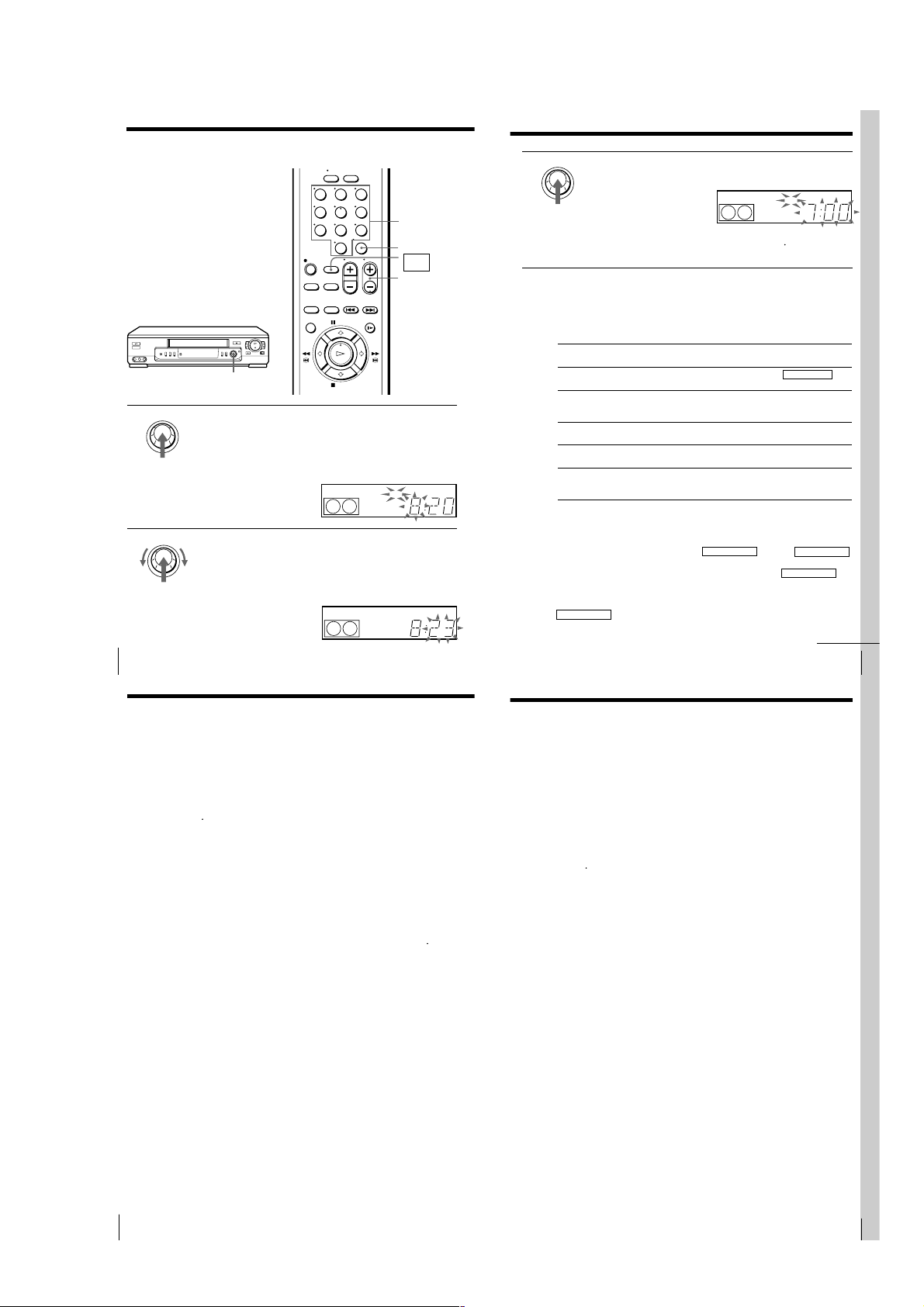
Press the EASY TIMER knob.
The START indicator appears in the display window.
If the clock has not been set,
“–:– –” appears. Go to step 2
in “Setting or changing the
Easy Clock” on page 28.
123
456
789
0
SP
ENTER (AM/PM)
EASY
TIMER
CH +/–
SP/EP
START
AM
APC
1-6
Recording TV programs using the Easy Timer function (continued)
29
Basic Operations
Basic Operations
3
Press the EASY TIMER knob to confirm the clock setting.
The VCR enters the timer recording setting mode.
To continue the Easy Timer
setting, go to step 2 in
“Setting the Easy Timer” on
page 26.
To quit the Easy Timer setting mode without changing any settings,
press the EASY TIMER knob repeatedly until the
t
indicator
appears in the display window.
To set the timer and clock setting using the remote commander
You can also use the remote commander to set the Easy Timer and Easy
Clock. The operations on the VCR and the remote commander correspond as
follows:
To
Confirm the setting and go to
the next setting
Change the time by 15 minutes
(in START/STOP mode)
Change the time by one minute
(in START/STOP mode)
Select the channel
Change the hour/minute by
one hour/minute (in CLOCK
mode)
Do this on the VCR
Press EASY TIMER knob
Turn EASY TIMER knob
or hold CHANNEL +/–
down
Press CHANNEL +/–
Turn EASY TIMER knob
or press CHANNEL +/–
Turn EASY TIMER knob
or press CHANNEL+/–
Do this on the remote
commander
Press EASY TIMER
Hold CH +/– down
Press CH +/–
Press CH +/– or INPUT
SELECT
Press CH +/–
You can also use the number buttons to set the clock, start and stop times,
and the channel you want to record. Just press the number buttons to enter
the hours and minutes. For example:
• To set the clock to “8:20”, press 0, 8, EASY TIMER , 2, 0 and EASY TIMER
in sequence.
• To set the start or stop time to “8:20”, press 0, 8, 2, 0 and EASY TIMER in
sequence.
If you make a mistake, re-enter the correct digits before pressing
EASY TIMER .
EASY TIMER
SP
APC
START
PM
continued
31
Basic Operations
Basic Operations
Tips
• (SLV-ED99PL and ED55PL)
To record from a source connected to LINE-1 IN or LINE-2 IN jacks, press INPUT
SELECT or CH +/– or turn the EASY TIMER knob to display “L1” or “L2” in the
display window.
• (SLV-ED22PL)
To record from a source connected to LINE-1 IN jacks, press INPUT SELECT or CH
+/– or turn the EASY TIMER knob to display “L” in the display window.
Notes
• You cannot set the Easy Timer if eight programs have already been set.
• You can set the timer for only one program using the Easy Timer function. If you
want to set the timer for other programs, use the TIMER SET/CHECK menu. For
details, see page 32.
• You cannot set the date using the Easy Timer function. Set the date using the
CLOCK SET menu if you want to set the timer with the menu. For details, see page
11.
• The
t
indicator flashes in the display window when you complete the setting with
no tape inserted.
Setting or changing the
Easy Clock
When “–:– –” is displayed in the VCR’s
display window, the VCR clock has not
been set. You need to set the clock using
the Easy Clock function before setting
the timer. You can also change the
current time using the Easy Clock
function.
EASY TIMER
knob
EASY TIMER
1
2
• When “–:– –” is displayed in the display window, press the
EASY TIMER knob.
• To change the clock setting, press and hold the EASY TIMER knob
on the VCR for more than three seconds.
The CLOCK indicator and the current clock setting appear in the
display window.
EASY TIMER
Set the current time using the EASY TIMER knob.
1 Turn the EASY TIMER knob clockwise or counterclockwise to
enter the current hour.
2 Press the EASY TIMER knob to confirm the hour setting.
3 Turn the EASY TIMER knob to increase or decrease the minutes
setting by a minute.
Press ENTER (AM/PM) to
change AM and PM.
123
456
789
0
SP
SP
CLOCK
CLOCK
Number
buttons
ENTER (AM/PM)
EASY
TIMER
CH +/–
START
AM
APC
START
AM
APC
Basic Operations
28
Recording TV programs using the Easy Timer function (continued)
To stop recording
To stop the VCR while recording, press x STOP.
30
To check or change the timer setting
Press the EASY TIMER knob repeatedly until the setting you want to check
or change flashes. Then re-enter the new setting, if necessary. If you do not
want to change any of the settings, press the EASY TIMER knob repeatedly
until the
indicator appears in the display window.
t
You can also change the timer setting using the TIMER SET/CHECK menu.
For details, see page 38.
To cancel the timer setting
To cancel the Easy Timer setting while doing the setting, press CLEAR on the
remote commander or press CHANNEL + and – on the VCR at the same
time.
To use the VCR after setting the timer
To use the VCR before a timer recording begins, just press ?/1. The
indicator turns off and the VCR switches on. Remember to press ?/1 to reset
the VCR after using the VCR.
You can also do the following tasks while the VCR is recording:
• Reset the counter.
• Display tape information on the TV screen.
• Check the timer settings.
• Watch another TV program.
To watch the recorded program right after the Easy Timer recording
The SEARCH indicator starts flashing when the VCR finishes the Easy Timer
recording. To watch the recorded program, press the EASY TIMER knob. The
VCR turns on, starts searching, then automatically starts playback from the
beginning of the recording. For details, see page 42.
Basic Operations
t
1-7
Setting the timer
35
Additional Operations
Setting the
recording
duration time
After you have started recording in the
normal way, you can have the VCR stop
recording automatically after a specified
duration.
z REC
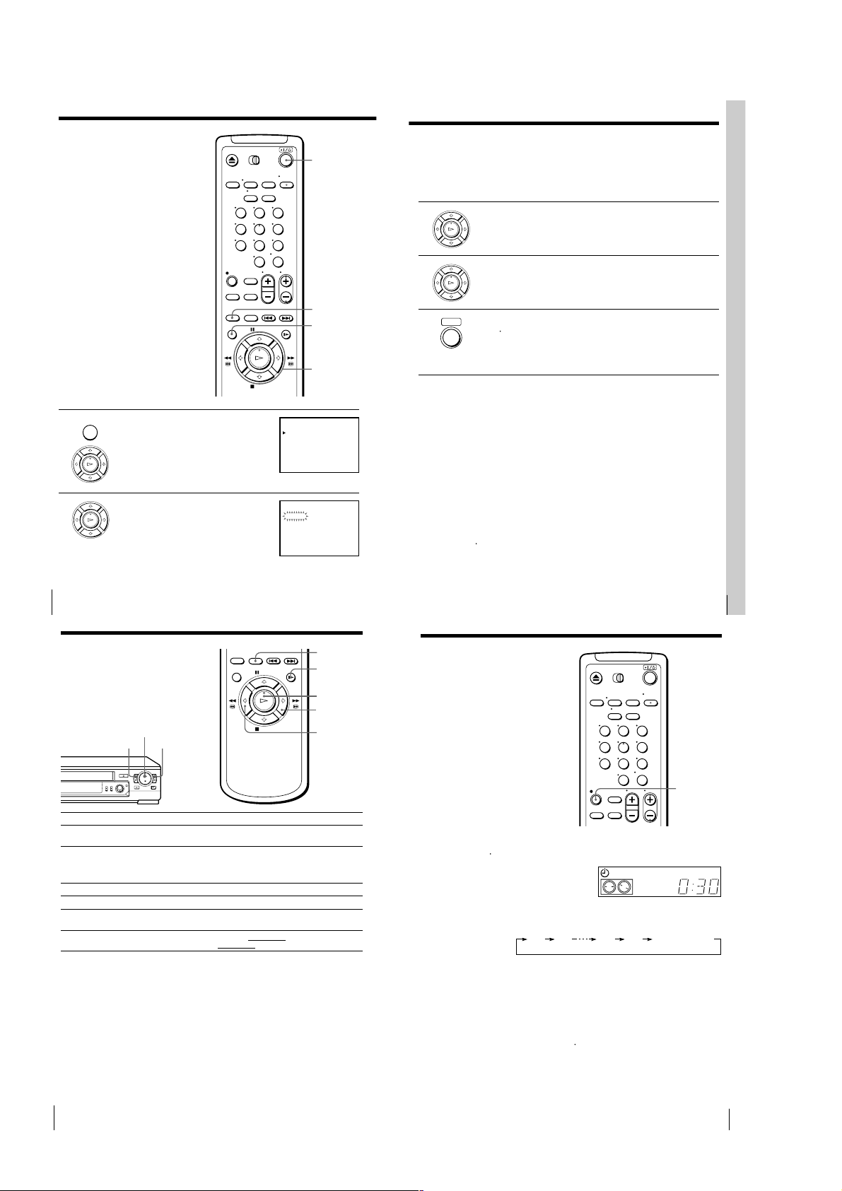
1
While recording, press z REC.
The
t
indicator appears in the display window.
2
Press z REC repeatedly to set the duration.
Each press advances the time in increments of 30 minutes.
The tape counter decreases minute by minute to 0:00, then the VCR
stops recording and turns off automatically.
To extend the duration
Press z REC repeatedly to set to the new duration.
To cancel the duration
Press z REC repeatedly until the
t
indicator disappears and the VCR
returns to normal recording mode.
To stop recording
To stop the VCR while recording, press x STOP.
0:30 1:00 6:005:30 Normal recording
123
456
789
0
SP
APC
VIDEO
manually
You can preset up to eight programs at a
time.
Before you start…
• Check that the VCR clock is set to the
correct time.
• Turn on your TV and set it to the
video channel.
• Insert a tape with its safety tab in
place. Make sure the tape is longer
than the total recording time.
MENU
1
2
Press MENU and select TIMER SET/
CHECK, then press OK.
PLAY
OK
Set the date, start and stop times, channel
number and tape speed:
PLAY
OK
1 Press , to flash each item in turn.
2 Press M/m to set each item.
To correct a setting, press < to return to
that setting and reset.
123
456
789
0
?/1
INPUT SELECT
MENU
OK
M/m/</,
TIMER SET / CHECK
DATE
– / –– –: –– –: –– ––
– / –– –: –– –: –– ––
– / –– –: –– –: –– ––
– / –– –: –– –: –– ––
– / –– –: –– –: –– ––
– / –– –: –– –: –– ––
– / –– –: –– –: –– ––
– / –– –: –– –: –– ––
TIMER SET / CHECK
DATE
11
– / –– –: –– –: –– ––
– / –– –: –– –: –– ––
– / –– –: –– –: –– ––
– / –– –: –– –: –– ––
– / –– –: –– –: –– ––
– / –– –: –– –: –– ––
– / –– –: –– –: –– ––
11/ 16
START STOP CH
11/ 16
START STOP CH
/16 – :–– –: –– ––
THU
To record the same program every day or the same day every week,
press m while the date is flashing. For details, see “Daily/weekly
recording” on this page.
To record from a source connected to the line inputs jacks, press
INPUT SELECT or CH +/– to display “L1” or “L2” (or “L” for
SLV-ED22PL) in the “CH” position.
3 Press / to confirm the setting.
PLAY
The cursor (B) appears at the beginning of the line. To enter another
OK
setting, move the cursor to the next line and repeat step 2.
4 Press OK.
PLAY
OK
5 Press ?/1 to turn off the VCR.
• ]/1
indicator lights up in the display window and the VCR
The
t
stands by for recording.
To record from other equipment, leave the connected equipment
switched on.
Basic Operations
To stop recording
THU
–
–
–
–
–
–
–
–
THU
SP
–
–
–
–
–
–
–
To stop the VCR while recording, press x STOP.
Daily/weekly recording
In step 2 above, press m to select the recording pattern. Each time you press
m, the indication changes as shown below. Press M to change the indication
in reverse order.
the current date t SUN-SAT t MON-SAT t MON-FRI t EVERY SAT t
..... t EVERY MON t EVERY SUN t 1 month later t (dates count down)
t the current date
Tips
• To set the channel, you can also use the CH +/– or number buttons.
• To set the tape speed, you can also use SP/EP.
Note
• The
indicator flashes in the display window when you set the timer with no tape
t
inserted.
Basic Operations
32
Additional Operations
Playing/searching
at various speeds
Playback options
View the picture during
fast-forward or rewind
Play at high speed
Play at twice the normal speed
Play in slow motion
Play frame by frame
Rewind and start play
Additional Operations34
H PLAY
m 3 REW M # FF
To resume normal playback
Press H PLAY.
Tips
• Adjust the picture using TRACKING +/– on the VCR if:
– streaks appear while playing in slow motion.
– the picture shakes while pausing.
To set tracking to the center position, press both buttons at the same time.
• If noise appears during pause or frame-by-frame playback, first switch to the slow
motion playback, then adjust the picture using TRACKING +/– on the VCR.
Notes
• The sound is muted during these operations.
• In EP mode, noise may appear or there may be no colour.
• Tapes recorded in the LP mode on other VCRs can be played back on this VCR but
the picture quality cannot be guaranteed.
• The picture may have snow when playing at high speed in reverse.
×2
y SLOW
H PLAY
M # FF
m 3 REW
Operation
During fast-forward, hold M # FF down. During rewind, hold
m 3 REW down.
• During playback, press M # FF or m 3 REW on the remote
commander.
• During playback, hold M # FF or m 3 REW down. When
you release the button, normal playback resumes.
During playback or pause, press ×2.
During playback or pause, press y SLOW.
During pause, press M # FF or m 3 REW on the remote
commander. Hold the button down to play one frame each second.
During stop, press H PLAY
0 3 REW down
on the VCR.
on the VCR while holding
1-8
Basic Operations
33
Synchronized recording (SLV-ED99PL
37
Additional Operations
4
Press SP/EP to select the tape speed.
5
Hold down SYNCHRO REC for more than two seconds.
The SYNCHRO REC button lights up and the VCR stands by for
recording.
The VCR automatically turns on and starts recording when it receives video
signals from the connected equipment.
To cancel the Synchronized recording
Press SYNCHRO REC so that the button’s light turns off.
To stop recording
Press x STOP while recording.
The VCR automatically stops recording when the tape reaches the end or
when the other equipment stops transmitting the video signals.
Notes
• Some TVs or other equipment automatically turn off in a certain time if you do not
operate it after it turns on with the timer. In this case the Synchronized Recording
also stops automatically.
• The Synchronized Recording starts and stops according to the signals from the
connected equipment. Refer also to the instruction manual of the connected
equipment for its timer function.
• Some equipment keeps transmitting signals even though the power is off. In this
case, the Synchronized Recording feature does not work because the VCR will not
be able to know when to start recording. To record the program, set the timer on the
VCR. If you use a satellite tuner or a cable TV decoder, make sure to turn it on. For
details, see “Setting the timer manually”.
• If the settings for timer recording and Synchronized Recording overlap, the
program that starts first has priority and the second program starts recording only
after the first program has finished.
39
Additional Operations
3
Press M/m to select the setting you want to change or cancel:
• To change the setting, press </, to flash the item you want to
change, and press M/m to reset it. Then, press , repeatedly until
the cursor (B) appears at the beginning of the line.
• To cancel the setting, press CLEAR.
4
Press OK.
If any timer settings remain, turn off the VCR to return to recording
standby.
When the timer settings overlap
The program that starts first has priority and the second program starts
recording only after the first program has finished. If the programs start at
the same time, the program listed first in the menu has priority.
Program 1
Program 2
Will be cut off
only)
The Synchronized Recording feature enables you to record from the
connected equipment such as a satellite tuner, a cable TV decoder or a TV
that has a timer function. Once you set the timer on the other equipment, the
VCR will start recording the program synchronized with the timer.
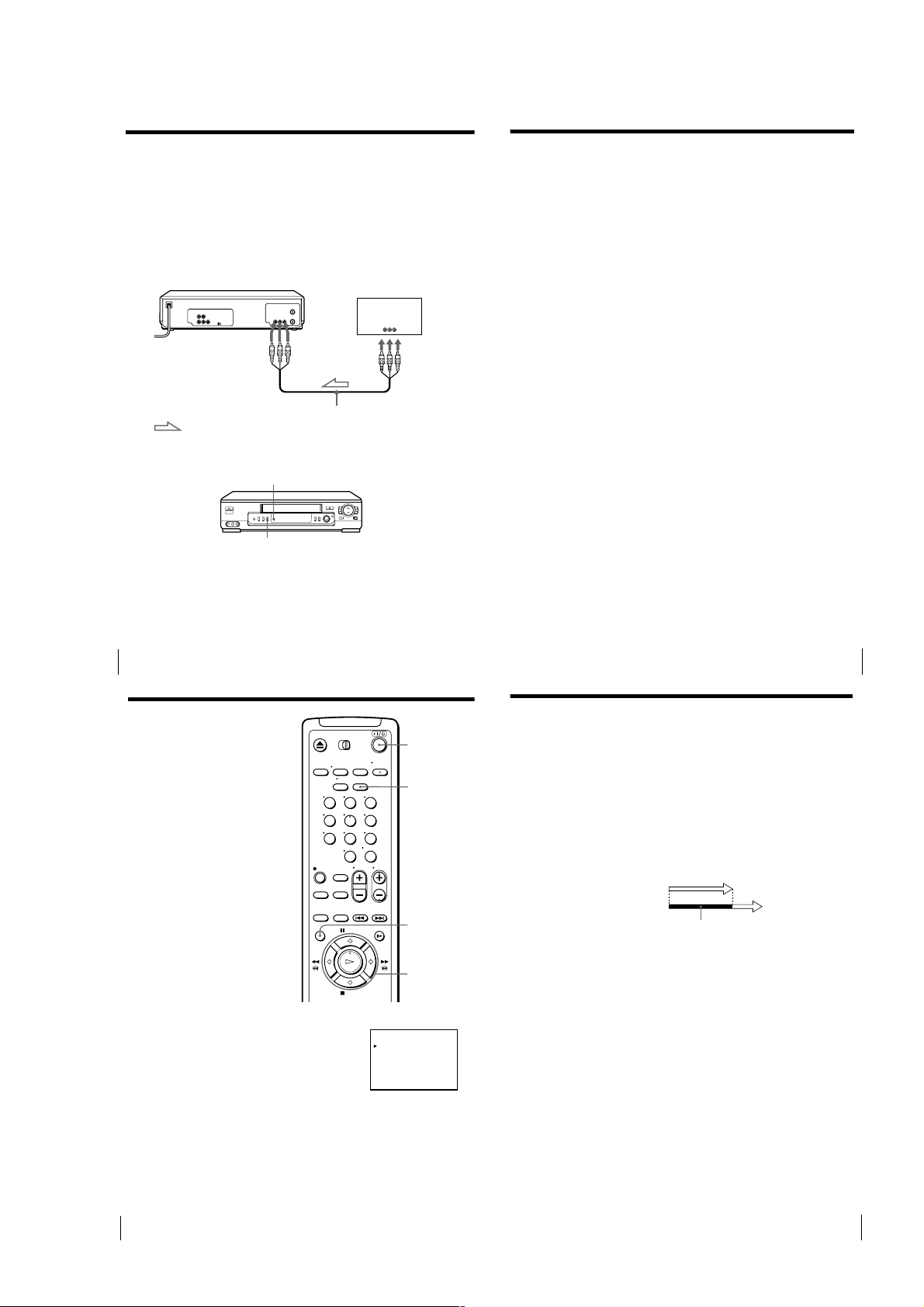
How to connect to use this function
Connect the other equipment to the LINE-1 IN jacks of this VCR.
This VCR (Recorder)
Satellite tuner, etc.
LINE-1 IN
: Signal flow
VMC-810HG audio/video cable (not supplied)
To prepare the Synchronized recording
SYNCHRO
REC
SP/EP
1
Press INPUT SELECT or CH +/– on the remote commander to display
“L1” in the display window.
2
Set the timer on the equipment to the time of the program you want to
record, then turn it off.
3
Insert a tape with its safety tab in place. Make sure the tape is longer
than the total recording time.
Additional Operations
36
Checking/
changing/
canceling timer
settings
Before you start…
• Turn on your TV and set it to the
video channel.
1
Press ?/1 to turn on the VCR.
2
Press MENU and select TIMER SET/CHECK:
• If you want to change or cancel a setting,
go on to the next step.
• If you do not need to change the settings,
press OK, then turn off the VCR to return
to recording standby.
LINE OUT
123
456
789
0
TIMER SET / CHECK
?/1
CLEAR
MENU
OK
M/m/</,
/17
FRI
/25
SAT
SUN
11/ 16
START STOP CH
7:00 8:00 6
AM
AM
10
:3011:15 50
PM
PM
1:00 3:00 L
PM
PM
AM
PM
11
:55 1:30 4
DATE
11
11
MON – SAT
EVERY
– / –– –: –– –: –– ––
– / –– –: –– –: –– ––
– / –– –: –– –: –– ––
– / –– –: –– –: –– ––
THU
SP
EP
2
EP
SP
2
–
–
–
–
Additional Operations
38
1-9
Recording stereo and bilingual
43
Additional Operations
Searching using
the index
function
The VCR marks the tape with an index
signal at the point where each recording
begins. Use these signals as references to
find a specific recording. The VCR can
search up to 99 index signals ahead of or
behind the current position. You can
either use the INDEX SEARCH buttons
on the remote commander or the
SEARCH button and EASY TIMER
knob on the VCR.
Using the INDEX SEARCH
buttons on the remote
commander
1
Insert an indexed tape into the VCR.
2
Press ./> INDEX SEARCH repeatedly to specify how many
index signals ahead or behind you want to search:
• To search ahead, press > INDEX
SEARCH.
• To search backwards, press .INDEX
SEARCH.
The VCR starts searching and the index
number on the TV screen counts down to
zero. The playback starts from the point
about five seconds ahead of the specified
index mark.
./>
INDEX
SEARCH
continued
programs (SLV-ED99PL only)
Recording stereo programs
This VCR automatically receives and records stereo programs. When a stereo
program is received, the STEREO indicator lights up. If there is noise in the
stereo program, set AUTO STEREO in the SET UP MENU to OFF. The sound
will be recorded in monaural (on both hi-fi and normal audio tracks) but
with less noise. For details, see page 48.
Recording bilingual programs
Normally, this VCR records only the main sound. When a SAP (Second
Audio Program) is received, the SAP indicator appears on the TV screen for
a few seconds. To record only SAP sound, set TUNER AUDIO in the SET UP
MENU to SAP. For details, see page 48.
Selecting the sound during playback
Press AUDIO MONITOR to select the sound you want. (If you are recording,
the sound being recorded will not change.)
To listen to
Stereo
Left channel
Right channel
Monaural sound on the
normal audio track*
* Usually the mixed sound of left and right channels (monaural)
On-screen display
STEREO
L CH
R CH
No indicator
Display window
STEREO
STEREO
STEREO
No indicator
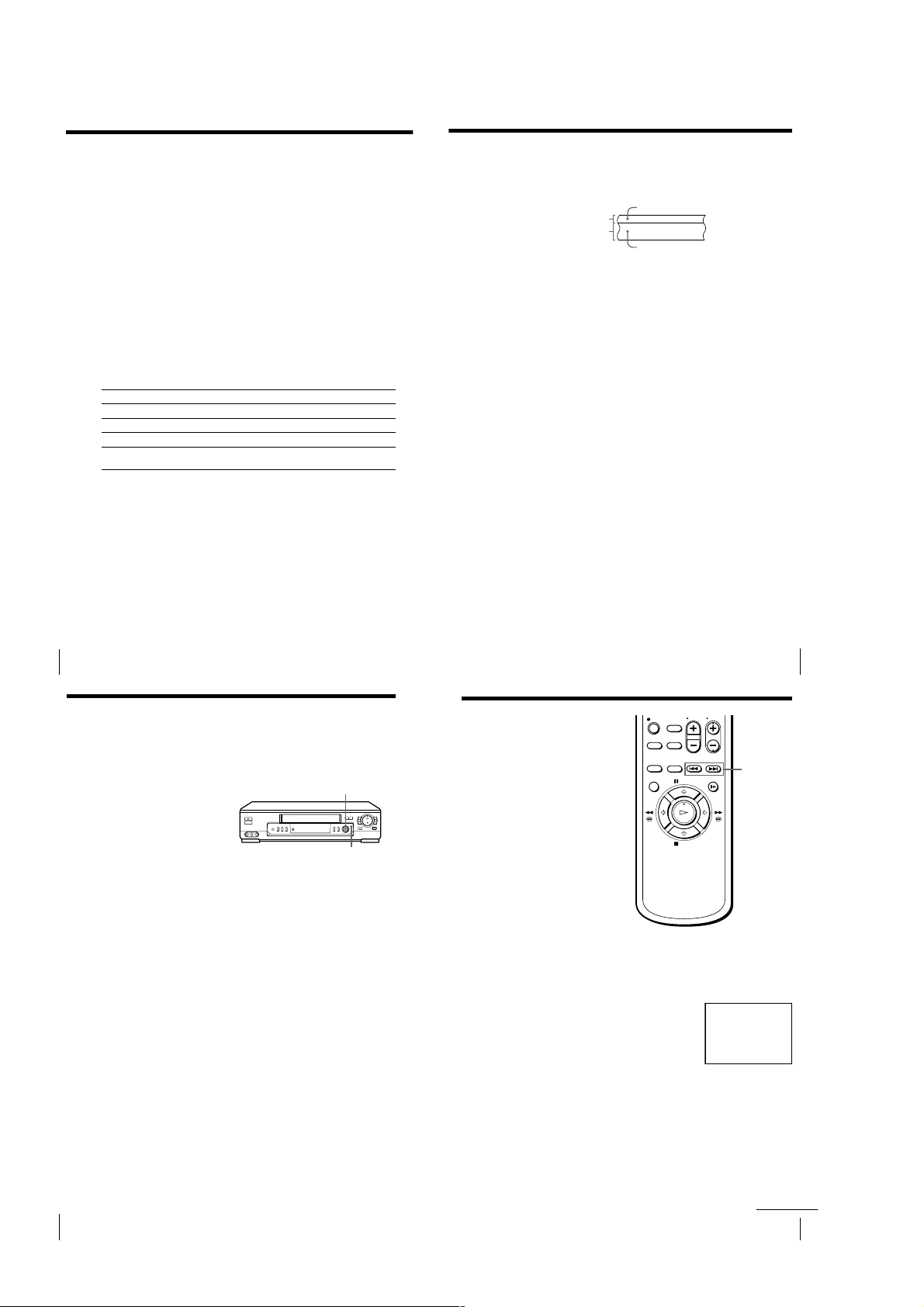
How sound is recorded on a video tape
The VCR records sound onto two separate tracks. Hi-fi audio is recorded
onto the main track along with the picture. Monaural sound is recorded onto
the normal audio track along the edge of the tape.
Normal audio track
Hi-fi audio track
(main track)
Notes
• To listen to the playback sounds in stereo, you must use the A/V connections.
• When you play a tape recorded in monaural, the sound is heard in monaural
regardless of the AUDIO MONITOR setting.
• If the AUDIO MONITOR button does not function, check that AUDIO MIX in the
SET UP MENU is set to OFF. For details, see page 48.
Monaural sound
Stereo sound
(left/right channels)
Additional Operations
40
Searching the
beginning of an
Easy Timer
recorded program
If you record a program using the Easy
Timer function, you can easily find the
beginning of the recording with this
SEARCH function. The SEARCH
indicator flashes when the VCR finishes
the Easy Timer recording.
Press the EASY TIMER knob.
The VCR turns on, rewinds to the beginning of the recorded program and
starts playback automatically.
Tip
• To stop the flashing of the SEARCH indicator, first turn the VCR on, then press the
SEARCH button. (Do not press any button at this point, otherwise this SEARCH
mode will be canceled.) To start the SEARCH function, press the SEARCH button
once. If you press the SEARCH button repeatedly, you can enter the index search or
Time Search mode.
For details, see pages 44 and 45.
Notes
• This SEARCH function will be canceled (the SEARCH indicator turns off) if:
– The VCR starts recording other programs.
– You press H PLAY, M # FF, m 3 REW or A EJECT button (while the VCR is
on).
• With this SEARCH function, you can find the beginning of a program recorded
using the Easy Timer function only.
EASY TIMER
knob
SEARCH
Additional Operations
8
INDEX
SEARCH
41
Additional Operations42
1-10
Searching using the index function (continued)
47
Additional Operations
About the Adaptive Picture Control (APC) function
The Adaptive Picture Control (APC) function automatically improves
recording and playback quality by adjusting the VCR to the condition of the
video heads and tape. To maintain better picture quality, we recommend that
you set APC to ON in the SET UP MENU (with the APC indicator in the
display window lit).
APC playback
The APC function automatically works on all types of tapes, including rental
tapes and tapes that were not recorded with APC.
APC recording
Whenever you insert a tape and start recording at the first time, the VCR
adjusts to the tape using the APC function (the APC indicator flashes
rapidly). This adjustment is retained until the tape is ejected.
To deactivate the APC function
Press MENU and select SET UP MENU, then set APC to OFF. The APC
indicator in the display window goes off.
Tip
• To set the tracking to the center position, press TRACKING + and – buttons at the
same time.
Notes
• The auto tracking adjustment cannot be guaranteed to work with tapes recorded in
the LP mode on other VCRs.
• There is a delay of a few seconds before the VCR actually starts recording while the
VCR analyzes the tape. To avoid the delay, first set the VCR to recording pause (the
APC indicator flashes slowly) and press z REC to have the VCR analyze the tape.
After the APC indicator stops flashing, press X PAUSE to start recording
immediately. If you press X PAUSE
before the APC indicator stops flashing, the
APC function is canceled.
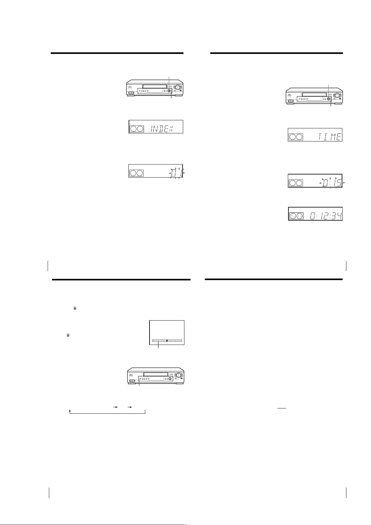
Using the SEARCH button
and EASY TIMER knob on
the VCR
1
Press SEARCH on the VCR repeatedly until “INDEX” appears in the
display window (the SEARCH indicator lights up).
2
Turn the EASY TIMER knob to specify how many index signals ahead
or behind you want to search:
• To search ahead, turn the EASY TIMER knob clockwise.
• To search backwards, turn the EASY TIMER knob counterclockwise.
3
Press the EASY TIMER knob.
The VCR starts searching. The playback starts (the SEARCH indicator
turns off) from the point about five seconds ahead of the specified index
mark.
To stop searching
Press x STOP.
Note
• No index signal will be added when recording starts from recording pause.
However, an index signal will be marked if you change the channel during
recording pause.
Additional Operations
44
Searching using
EASY TIMER
knob
SEARCH
SP
SP
START
APC
APC
the Time Search
function
You can easily find a specific point on a
tape by using the Time Search function.
For example, you can find a recorded
portion 15 minutes ahead of or behind
the current position of a tape by using
the Time Search function.
1
Press SEARCH repeatedly until “TIME” appears in the display window
(the SEARCH indicator lights up).
2
Turn the EASY TIMER knob clockwise or counterclockwise to set the
length of the time portion you want the VCR to fast-forward or rewind
the tape. Each turn on the knob increases or decreases the duration by
15 minutes.
For example, if you want to watch a recorded portion 15 minutes ahead
of the current position, turn the EASY TIMER knob once clockwise.
To change the time by one
minute, press CHANNEL
+/–.
3
Press the EASY TIMER knob.
The VCR starts searching and the tape counter starts counting until it
reaches the specified point.
The VCR starts playback automatically when the tape counter reaches
the specified point (the SEARCH indicator turns off).
To stop searching
Press x STOP.
Tip
• The VCR can search up to three hours ahead of or behind the current position of a
tape.
SP
SP
SP
EASY TIMER
knob
SEARCH
APC
APC
APC
Additional Operations
45
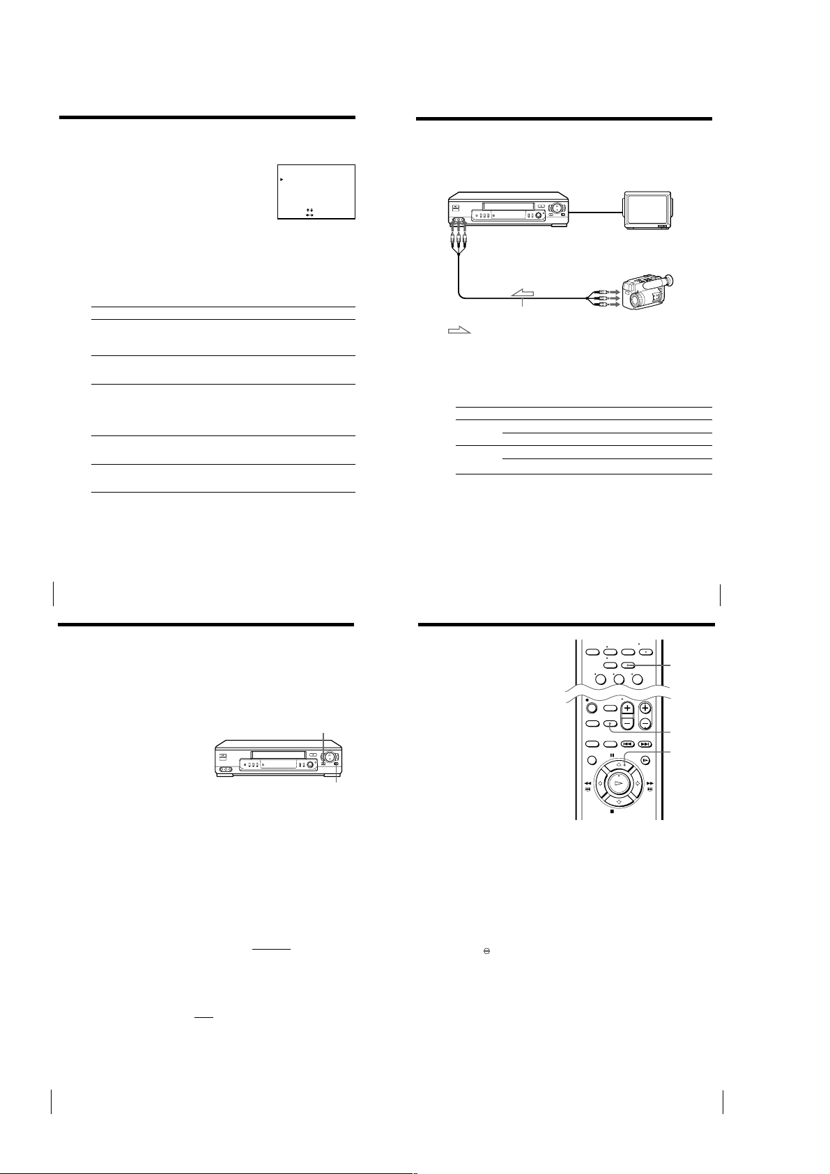
Adjusting the picture
Adjusting the tracking
Although the VCR automatically adjusts the tracking when playing a tape
(the
indicator flashes in the display window, then turns off), distortion
may occur if the tape was recorded in poor condition. In this case, manually
adjust the tracking.
Press the TRACKING +/– buttons on the VCR to
display the tracking meter. The distortion should
disappear as you press one of the two buttons (the
indicator lights up). To resume automatic
tracking adjustment, eject the tape and reinsert it.
About the R2 (Reality Regenerator) function
(SLV-ED99PL only)
The R2 function automatically
adjusts the picture to the most
suitable quality during playback.
When playback starts, the R
function activates and the R
button lights up.
Each pressing of the button changes the effect and indication in the display
window as follows:
2
2
SOFTREAL (status of playback started) DYNA (dynamic)
2
R
NORMAL TRACKING
Tracking meter
Additional Operations
46
1-11
Changing menu options
1
Press MENU and select SET UP MENU.
2
Press >/. to select the option to change, then press ?// to change
the setting.
3
Press OK to return to the original screen.
Menu choices
Initial settings are indicated in bold print.
Additional Operations
48
Menu option
AUTO ANT SEL
AUTO STEREO
(SLV-ED99PL
only)
AUDIO MIX
(SLV-ED99PL
only)
TUNER AUDIO
(SLV-ED99PL
only)
APC
Set this option to
ON if your TV is connected only to VHF/UHF OUT on the VCR.
To play a tape, set the TV to the VCR channel (channel 3 or 4).
OFF if your TV is connected to both VHF/UHF OUT and LINE-1
OUT on the VCR. To play a tape, set the TV to the VCR input.
ON to receive stereo programs. OFF to reduce noise; the sound
changes to monaural.
ON to listen to the sound recorded on hi-fi and normal audio
tracks at the same time. The AUDIO MONITOR button will not
function.
OFF to listen to hi-fi and normal audio tracks separately. Select the
sound using the AUDIO MONITOR button.
MAIN to record the main sound. SAP to record the SAP (Second
Audio Program) sound.
ON to switch on the APC (Adaptive Picture Control) function and
improve picture quality.
OFF to switch off APC.
SET UP MENU
AUTO ANT SEL
AUTO STEREO
AUDIO MIX
TUNER AUDIO
APC
SELECT
SET
[]
:
[
:
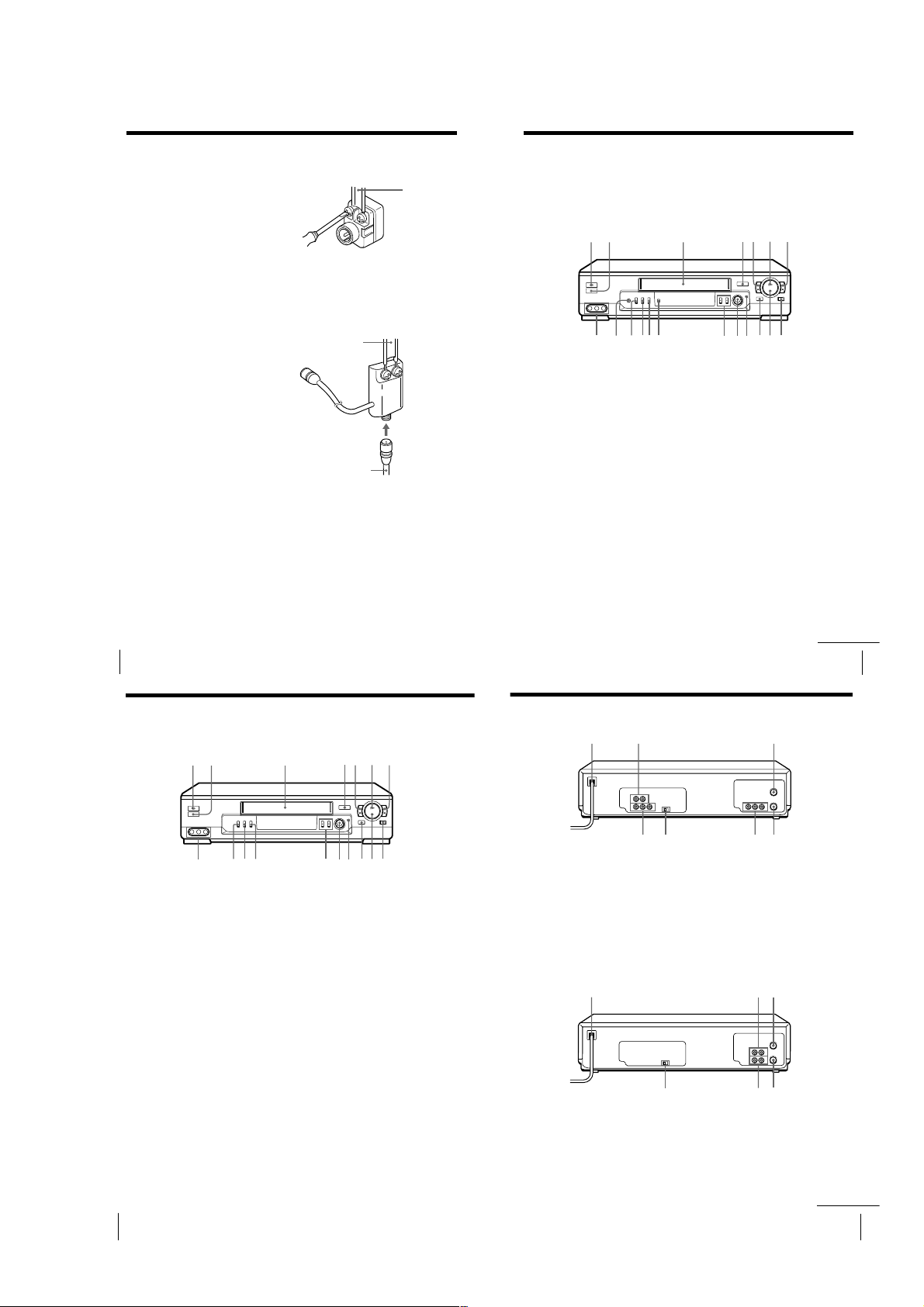
Editing
Hooking up to a VCR
ON• OFF
ON• OFF
ON•OFF
MAIN• SAP
ON• OFF
]
How to hook up to record on this VCR
This VCR (Recorder)
LINE-2 IN
LINE OUT
VMC-810HG audio/video cable (not supplied)
: Signal flow
TV
Other VCR (Player)
How to hook up to a stereo system (SLV-ED99PL only)
Connect LINE-2 IN AUDIO on this VCR to the audio output jacks on the
stereo system, using the RK-C510HG audio cable (not supplied).
Tips
• (SLV-ED55PL and ED22PL)
Use the following audio/video cable according to the type of the other VCR.
Jack
LINE-1 IN
LINE-2 IN
(SLV-ED55PL
only)
• (SLV-ED99PL)
If the other VCR is a monaural type and connected to this VCR’s LINE-2 IN jacks,
connect the audio plug to the AUDIO L (white) jack. The sound is recorded on both
right and left channels. When connecting to the AUDIO R (red) jack, the sound is
recorded only on the right channel.
• You can also use the LINE-1 IN jacks instead. If the other VCR is a monaural type,
the sound is recorded only on the channel whose jack is connected to the audio
plug. To record on both right and left channels, connect the audio plugs to the
AUDIO R/L jacks using a VMC-910HG audio/video cable (not supplied).
Notes
• Make sure you connect the plugs to jacks of the same color.
• If you connected this VCR to both the LINE IN and LINE OUT jacks of the other
VCR, select the input correctly to prevent a humming noise.
If the other VCR is: Use a cable such as:
Stereo type VMC-910HG (3-phono to 2-phono)
Monaural type VMC-710HG/720HG (2-phono to 2-phono)
Stereo type VMC-810HG (3-phono to 3-phono)
Monaural type VMC-910HG (3-phono to 2-phono)
Editing
49
Basic editing
(when recording on this VCR)
Before you start editing
• Turn on your TV and set it to the
video channel.
• (SLV-ED99PL and ED55PL)
Press INPUT SELECT or CH +/– to
display “L1” or “L2” in the display
window.
• (SLV-ED22PL)
Press INPUT SELECT or CH +/– to
display “L” in the display window.
• Press SP/EP to select the tape speed,
SP or EP.
1
Insert a source tape with its safety tab removed into the other
(playback) VCR. Search for the point to start playback and set it to
playback pause.
2
Insert a tape with its safety tab in place into this (recording) VCR.
Search for the point to start recording and press X PAUSE.
3
Press z REC and set it to recording pause.
4
To start editing, press the X PAUSE buttons on both VCRs at the same
time.
To stop editing
Press the x STOP buttons on both VCRs.
Tips
• To edit more precisely, press the X PAUSE buttons
• To cut out unwanted scenes while editing, press X PAUSE on this VCR when an
unwanted scene begins. When it ends, press X PAUSE again to resume recording.
Note
• If you start recording following the procedure above, the VCR won’t start recording
with the APC function. To record a tape with the APC function, press z REC again
during recording pause in step 3 so that the VCR analyzes the tape. Then when you
start recording in step 4, press X PAUSE immediately after the APC indicator stops
flashing. If you press X PAUSE
function is canceled.
0
Editing
X PAUSE
z REC
on the VCRs to release pause.
before the APC indicator stops flashing, the APC
Audio dubbing
(SLV-ED99PL only)
This feature lets you record over the
normal audio track. The monaural
sound previously recorded is replaced
while the original hi-fi sound remains
unchanged. Use this feature to add
commentary to a tape that you have
recorded with a camcorder.
Before you start editing
• Turn on your TV and set it to the
video channel.
• Press INPUT SELECT or PROG +/– to
display “L1” or “L2” in the display
window.
1
Insert a source tape into the stereo system (or the playback VCR).
Search for the point to start playback and set it to playback pause.
2
Insert a prerecorded tape into this (recording) VCR. Search for the end
of the section to be replaced and press X PAUSE.
Make sure that the tape has its safety tab in place.
3
Press CLEAR to reset the counter to “0:00:00.”
4
Rewind the prerecorded tape to the beginning of the section to be
replaced.
The VCR pauses.
5
Press AUDIO DUB.
indicator appears in the display window.
The
6
To start editing, press the X PAUSE buttons on this VCR and the stereo
system (or other VCR) at the same time.
When the counter reaches “0:00:00”, audio dubbing stops automatically.
To stop while editing
Press the x STOP buttons on this VCR and the stereo system (or other VCR).
To listen to both the hi-fi and normal audio
Set AUDIO MIX to ON in the SET UP MENU (page 48). Use this feature to
listen to dubbed audio over the original hi-fi audio. When AUDIO MIX is set
to ON, the AUDIO MONITOR button does not function. Remember to reset
AUDIO MIX to OFF after playing the tape.
123
CLEAR
AUDIO DUB
X PAUSE
Editing
51
1-12
Additional Information
57
Additional Information
Index to parts and controls
Front panel (SLV-ED99PL)
Refer to the pages indicated in parentheses ( ) for details.
1 ?/1 POWER switch (33)
2 Remote sensor (5)
3 Tape compartment
4 A EJECT button (21)
5 m 3 REW (rewind) button (21, 34)
6 H PLAY button (21)
7 M # FF (fast-forward) button
(21, 34)
8 z REC (record) button (24)
9 x STOP button (21)
0 X PAUSE button (21)
qa SEARCH button/indicator (42, 44,
45)
qs EASY TIMER knob (26, 42, 44, 45)
qd CHANNEL/TRACKING +/–
buttons (24, 46)
qf SYNCHRO REC button (36)
qg SP (Standard Play)/EP (Extended
Play) button (24)
qh INPUT SELECT button (25)
qj ONE TOUCH TUNING button (13)
qk R
2
(Reality Regenerator) button (46)
ql LINE-2 IN VIDEO/AUDIO L/R
jacks (49)
qh
8qg 0
13
4
5
2
67
9qaqsqdqjqkql qf
continued
59
Additional Information
Rear panel (SLV-ED99PL)
1 AC power cord
2 LINE-2 OUT AUDIO R/L jacks (8)
3 VHF/UHF IN connector (9)
4 VHF/UHF OUT connector (9)
5 LINE-1 IN AUDIO R/L/VIDEO
jacks (49)
6 LINE-1 OUT AUDIO R/L/VIDEO
jacks (7)
7 RF (Radio Frequency) UNIT switch
(10)
1 AC power cord
2 LINE-1 IN AUDIO/VIDEO jacks
(49)
3 VHF/UHF IN connector (9)
4 VHF/UHF OUT connector (9)
5 LINE-1 OUT AUDIO/VIDEO jacks
(8)
6 RF (Radio Frequency) UNIT switch
(10)
Rear panel (SLV-ED55PL and ED22PL)
213
457
6
21 3
4
5
6
continued
General setup information
Attaching the external
antenna connector
When using a 300-ohm twin lead cable
for VHF/UHF antenna, use the EAC-32
antenna connector (not supplied) to
connect the antenna to the VCR.
1
Loosen the screws on the antenna connector.
2
Wind the twin leads around the screws on the antenna connector.
3
Retighten the screws.
Attaching a UHF/VHF band
mixer
When using both 75-ohm coaxial cable
and 300-ohm twin lead cable for VHF/
UHF antenna, use the EAC-66 UHF/
VHF band separator/mixer (not
supplied) to connect the antenna to the
VCR.
1
Loosen the screws on the mixer.
2
Wind the twin leads around the screws on the mixer.
3
Retighten the screws.
4
Connect the 75-ohm coaxial cable to the mixer.
300-ohm twin
lead cable
75-ohm coaxial
cable
300-ohm twin
lead cable
EAC-32 Antenna
connector (not
supplied)
EAC-66
UHF/VHF
band
separator/
mixer (not
supplied)
Additional Information
52
Index to parts and controls (continued)
Front panel (SLV-ED55PL and ED22PL)
1 3
2
qh
1 ?/1 POWER switch (33)
2 Remote sensor (5)
3 Tape compartment
4 A EJECT button (21)
5 m 3 REW (rewind) button (21, 34)
6 H PLAY button (21)
7 M # FF (fast-forward) button
(21, 34)
8 z REC (record) button (24)
9 x STOP button (21)
Additional Information
8
4
67
5
9qaqsqdqj qf
8qg 0
0 X PAUSE button (21)
qa SEARCH button/indicator (42, 44,
45)
qs EASY TIMER knob (26, 42, 44, 45)
qd CHANNEL/TRACKING +/–
buttons (24, 46)
qf SP (Standard Play)/EP (Extended
Play) button (24)
qg INPUT SELECT button (25)
qh ONE TOUCH TUNING button (13)
qj LINE-2 IN VIDEO/AUDIO
(MONO) jacks (49) (SLV-ED55PL
only)
1-13
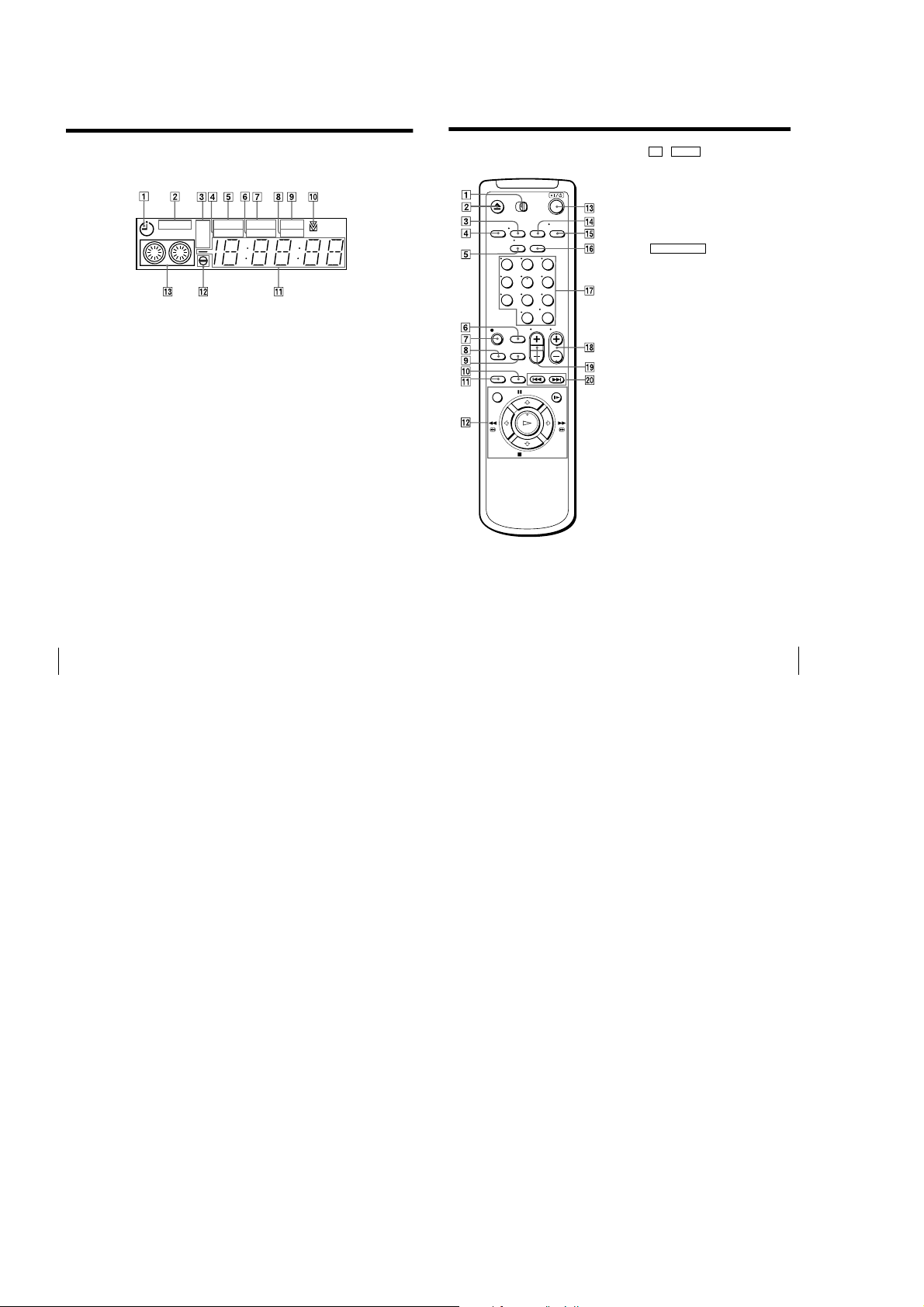
Index to parts and controls (continued)
61
Additional Information
Remote commander
1 TV / VIDEO remote control switch
(5)
2 Z EJECT button (21)
3 DISPLAY button (25)
4 TRINITRON TV SYNCHRO PLAY
button (22)
5 TV/VIDEO button (for TV) (6, 25)
6 EASY TIMER button (26)
7 z REC button (24, 35)
8 SP (Standard Play)/EP (Extended
Play) button (24)
9 AUDIO DUB (dubbing) button (51)
(SLV-ED99PL only)
0 ×2 button (34)
qa INPUT SELECT button (24, 33)
qs Tape/menu operation buttons
MENU button (11, 48)
X PAUSE/M button (21)
x STOP/m button (21)
m 3 REW (rewind)/< button
(21, 34)
M # FF (fast-forward)/, button
(21, 34)
H PLAY/OK button (21)
y SLOW button (34)
qd ?/1 (power) switch (6, 33)
qf R
2
(Reality Regenerator) button (46)
(SLV-ED99PL only)
qg AUDIO MONITOR button (40)
(SLV-ED99PL only)
qh CLEAR button (21, 39)
qj Number buttons and ENTER (AM/
PM) button (17, 27)
qk CH (channel) +/– buttons (6, 24)
ql VOL (volume) +/– buttons (for TV)
(6)
w; ./> INDEX SEARCH buttons
(43)
123
456
789
0
Display window
SP
STEREO
SAP
LP
EP
CLOCK
VIDEO
AMPM
START
STOP
APC
1 Timer indicator (27)
2 STEREO indicator (40)
(SLV-ED99PL only)
3 Tape speed indicator (24)
4 VIDEO indicator (10, 25)
5 CLOCK indicator (28)
6 AM/PM indicator (27)
7 START indicator (26)
Additional Information
60
8 APC (Adaptive Picture Control)
indicator (47)
9 STOP indicator (27)
q; Tracking indicator (46)
qa Time counter/clock/line/channel
indicator (21, 24, 28, 50)
qs Audio dubbing indicator (51)
qd Tape/recording indicator (24)
1-14 E
1-14
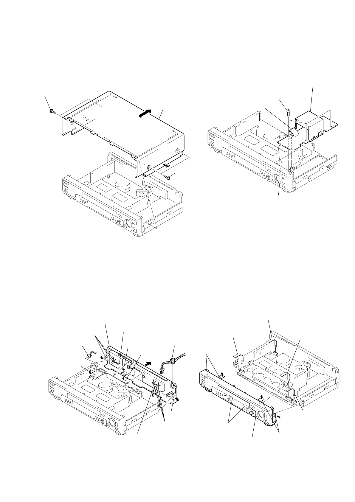
SLV-ED22/ED55/ED88/ED99
4 PSM17-501 board
1 Connector
(CN600)
2 Three screws
(B3)
3 Claw
4 Flat cable (FDS-6)
(CN103)
1 Flat cable (FMF-39)
(CN401)
2 Flat cable (FFJ-3)
(CN401) (ED55/ED99)
3 Flat cable (FKK-3)
(CN411)
5 Two claws
7 Two claws
6 Two claws
8 Front panel section
SECTION 2
DISASSEMBLY
Note: Follow the disassembly procedure in the numerical order given.
2-1. UPPER CASE REMOVAL 2-3. PSM17-501 BOARD REMOVAL
1 Two tapping screws
3 Upper case
2 Two tapping screws
2-2. REAR PANEL REMOVAL
qa Rear panel
6 Claw
7 Claw
4 Pin cable
(ED22TW/ED88/
ED99TW)
3 Connector
(CN702)
(ED22TW/ED88/
ED99TW)
5 Three claws
(ED88/ED99)
2 Harness
9 Three claws
8 Claw
2-4. FRONT PANEL SECTION REMOVAL
1 Power cord
(CN101)
0 Claw
(ED88/ED99: PL, KR)
2-1
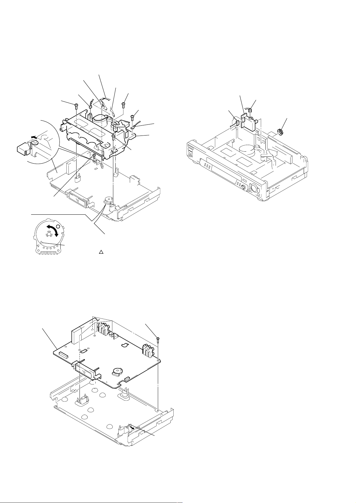
2-5. MECHANISM DECK REMOVAL
3 Flat cable
(FMD-15/16)
4 Flat cable (FAC-7)
(ACE head )
0 Screw
9 Screw
(BVTP3 × 12)
8 Claw
2 Flexible board
1 Connector
(FE head )
7 Screw
(B3)
(BVTP3 × 12)
5 Screw
(B3)
qs Mechanism
qa Screw
(BVTP3 × 12)
2-7. RF-048 BOARD REMOVAL
(ED22TW/ED88/ED99TW)
4 RF-048 board
2 Pin cable
1 Connector
(CN801)
3 Two nuts
6 Earth lug
deck
Note: When mounting the mechanism deck,
first align mark on the rotary switch.
2-6. MA-377 BOARD REMOVAL
3 MA-377 board
2 Five screws
(B3)
1 Connector
(CN600)
2-2
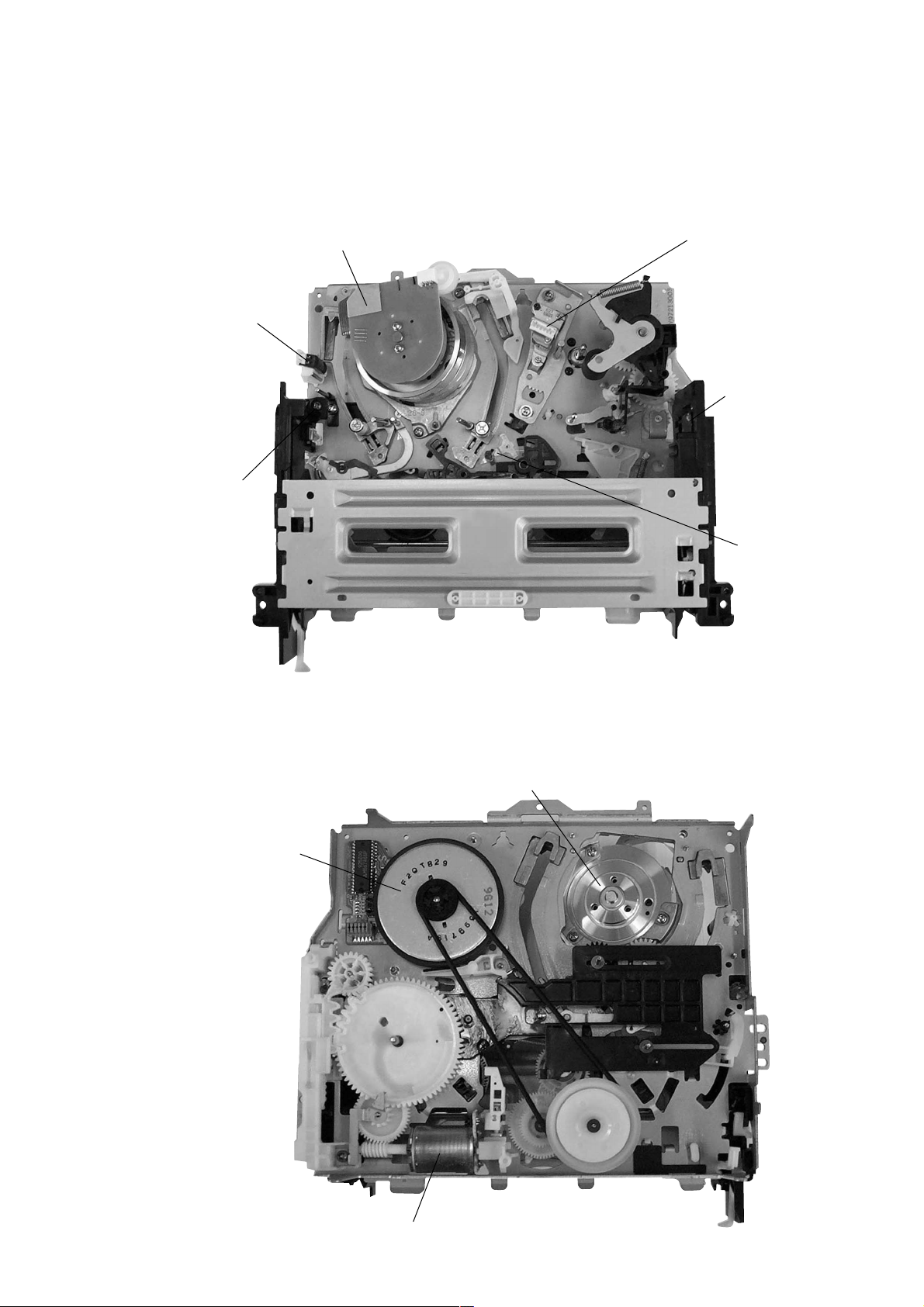
2-8. INTERNAL VIEWS
FE head
1-500-144-11
Q002
Tape top sensor
8-729-043-84
Drum assembly (M901) (DZH-71F-R)
1-759-360-11 (ED22)
Drum assembly (M901) (DZH-0A0A/Z-RP)
8-839-047-53 (ED88/ED99)
Drum assembly (M901) (DZH-0A2A/Z-RP)
8-839-049-53 (ED55)
ACE head assembly
A-6775-791-A
Q001
Tape end sensor
8-729-043-84
D001
Tape top/end LED
8-719-048-26
M902
Capstan motor
1-698-971-11
Drum assembly (M901) (DZH-71F-R)
1-759-360-11 (ED22)
Drum assembly (M901) (DZH-0A0A/Z-RP)
8-839-047-53 (ED88/ED99)
Drum assembly (M901) (DZH-0A2A/Z-RP)
8-839-049-53 (ED55)
M903
Cam motor assembly
X-3947-577-1
2-3
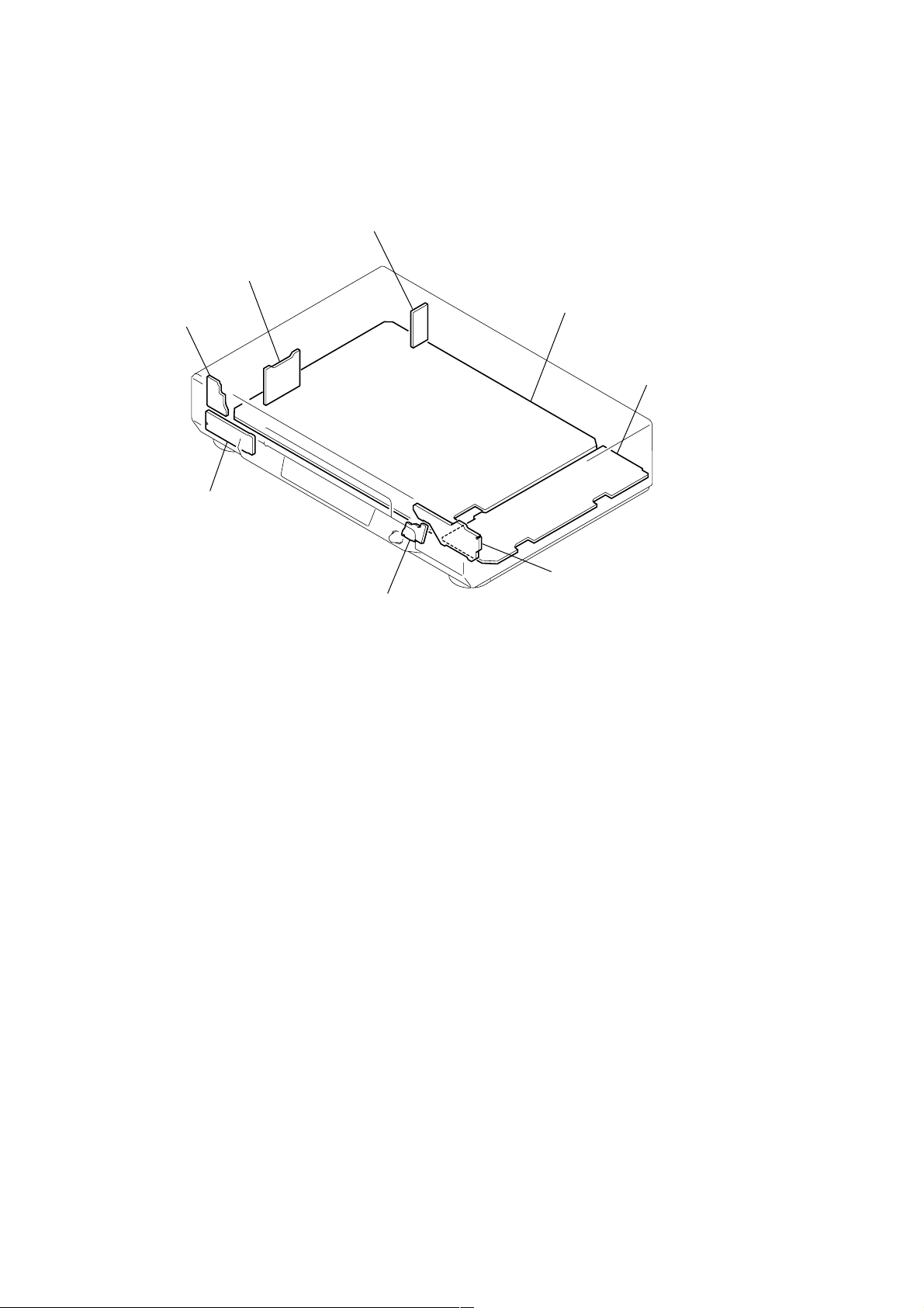
2-9. CIRCUIT BOARDS LOCATION
RF-048 (ED22TW/ED88/ED99TW)
(TUNER)
GK-12 (ED99KR)
(ZWEITON)
MF-321
(POWER SWITCH)
FJ-26
(ED55/ED99)
(FRONT IN)
MA-377
VIDEO, AUDIO, I/O,
SERVO/SYSTEM CONTROL,
(
TUNER, MODE CONTROL
KK-24
(EASY TIMER, SEARCH)
)
POWER BLOCK
(PSM17-501)
(POWER SUPPLY)
DS-92
(MODE CONTROL)
2-4
2-4 E
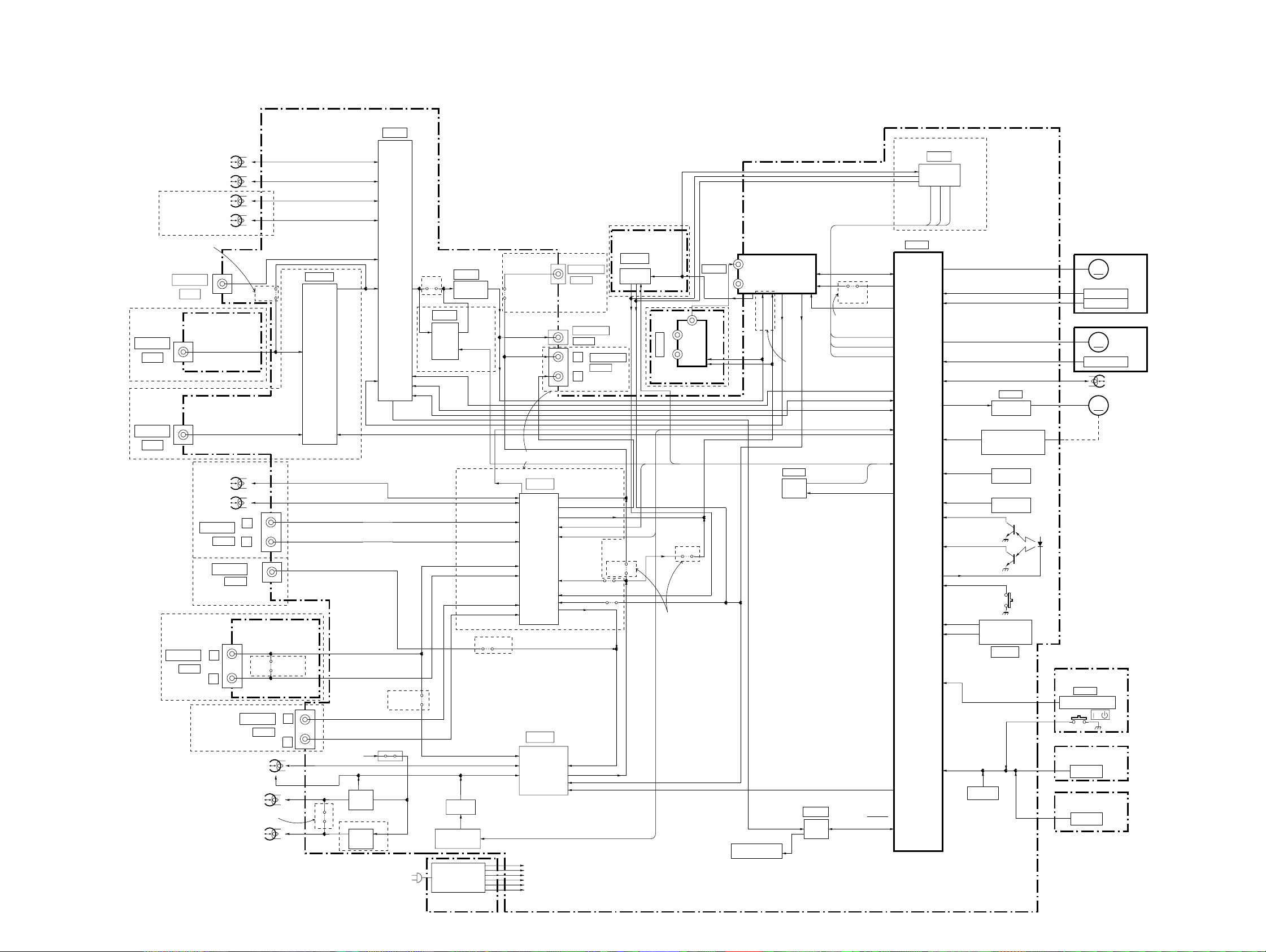
3-1. OVERALL BLOCK DIAGRAM
MA-377 BOARD
(SEE PAGE 4-9 to 4-24)
VIDEO HEAD
SP CH1
SP CH2
SECTION 3
BLOCK DIAGRAMS
IC201
(1/2)
Y/C
PROCESS
ED88/ED99:TW,PL
IC701
STEREO
SYSTEM
SLV-ED22/ED55/ED88/ED99
LINE-2 IN
VIDEO
ED55/ED99
LINE-3 IN
(SAT IN)
VIDEO
EXCEPT ED22
LINE-1 IN
ED55/ED99
LINE-2 IN
LP CH1
LP CH2
ED55/ED99:PL
VIDEO
FJ-26 BOARD(1/2)
(SEE PAGE 4-29)
LINE-1 IN
ED88/ED99
ED22/ED55
AUDIO
ED99:TW,KR
Hi-Fi
AUDIO HEAD
CH1
CH2
AUDIO
LINE-1 IN
AUDIO
L
R
FULL ERASE
JS202
L
R
FJ-26 BOARD(2/2)
(SEE PAGE 4-29)
JS533
LINE-3 IN
AUDIO
AUDIO HEAD
REC/PB
ERASE
EXCEPT ED99
LINE2
VIDEO
SAT
ED99:TW,KR
ED55
L
R
05
IC202
VIDEO
INPUT
SELECT
JS371
IN_SEL
SW 12V
BIAS
ERASE
OSC
T372,Q381
BIAS
ERASE
OSC
T371,Q375
ED99
PS331
ED55
AC IN
VDAT,VCLK
JS303
EXCEPT
ED99
JS291
IC291
ARC
ED99
HEAD CONTROL
SWITCH
SWITCHING
PSM-17-501 BOARD
(SEE PAGE 4-35)
IC101
HEAD
SWITCH
REG
(1/2)
OSD
IIC DATA,
IIC CLK
LINE-1 IN AUDIO L
LINE-1 IN AUDIO R
LINE-2 IN AUDIO L
LINE-2 IN AUDIO R
LINE-3 IN AUDIO L
LINE-3 IN AUDIO R
JS302,304
ED22/ED55
LINE-2 AUDIO IN
Q372,Q373
Q374
NA PB
ED22/ED55
JS909
JS911
ED88/ED99
IC360
Hi-Fi
AUDIO HIFI
PROCESS
IC201
NORMAL
30V
MTR12V
AN6V
-13V
+F
-F
AUDIO
PROCESS
LINE-1 OUT
AUDIO
LINE-1 OUT
VIDEO
L
R
LINE OUT 1 AUDIO L
LINE OUT 1 AUDIO R
MOD AUDIO
IIC DATA, IIC CLK
AF SWP
NORMAL
AUDIO IN
TUNER L,R
TUNER M
NORMAL AUDIO OUT
(2/2)
NORMAL AUDIO
IN
NORMAL AUDIO OUT
TU AUDIO
A MUTE
LINE-1 OUT
AUDIO
JS333
JS729
ED99:KR
GK-12 BOARD
(SEE PAGE 4-25)
IC001
ZWEITON
PROCESS
JS332
AERIAL
(IN/OUT)
RF-048 BOARD
(SEE PAGE 4-28)
ED22:TW/ED88/ED99:TW
IIC CLK
IIC DATA
JS707
ED22/ED55
SECON
MAIN/SAP
TUNER_MUTE
IC101
(2/2)
PLL DATA,
AERIAL
RFU
IN
TUNER
OUT
SIF
OUT
MOD V
TU VIDEO
TU AUDIO
MOD AUDIO
ED22:KR,PL/
ED55/ED99:KR,PL
IC142
IIC DATA
IIC CLK
EEP
WRITE CONT
ROM
PLL CLK
TU ENB
JS725
F MONO
ED88/
ED99:TW,PL
SECON
TUNER_MUTE
MAIN/SAP
COMP SYNC
VDAT, VCLK
RF SWP, RF ENV
NA PB,AF ENV, AF SWP
IN_SEL
IIC DATA, IIC CLK
SW2
AFT
SERVO/SYSTEM
CONTROL
DRUM VS
DRUM FG
DRUM PG
CAP VS
CAP FG
CTL+,-
CAM
MODE1-4
END LED
POWER FAIL
RESET
IC031
CAM MOTOR
DRIVER
S102
(CAM ENCODER)
ROTARY SWITCH
( )
MECHA POSITION
PH001
T REEL
FG
PH002
S REEL
FG
POWER FAIL DET
RESET PULSE
GENERATOR
Q001
T SENS
Q002
S SENS
S101
(REC PROOF)
CAM+,-
D001
M901
DRUM MOTOR
M
DRUM MOTOR
DRUM FG
DRUM PG
M902
CAPSTAN MOTOR
CAPSTAN
MOTOR
M
CAP FG
CTL HEAD
M903
M
CAM MOTOR
IC141
REMOCON
MF-321 BOARD
(SEE PAGE 4-29)
IC501
REMOTE CONTROL
RECEIVER
S501
/
DS-92 BOARD
(SEE PAGE 4-32)
FUNCTION
KEY
KK-24 BOARD
(SEE PAGE 4-32)
FUNCTION
KEY
MESECAM DET
ND451
FLUORESCENT
INDICATOR TUBE
IC451
DRIVER
KEY1,KEY2
A MUTE
S OUT
S CLK
FLD CS
FL
S IN
FUNCTION
KEY
3-1 3-2
 Loading...