

Page 1

Scale Unit
SH11 Series
Read all the instructions in the manual carefully before use and strictly follow them.
Keep the manual for future references.
Instruction Manual
Page 2

[For the customers in U. S. A.]
[ For EU and EFTA countries ]
WARNING
This equipment has been tested and found to comply
with the limits for a Class A digital device, pursuant to
Part 15 of the FCC Rules. These limits are designed
to provide reasonable protection against harmful
interference when the equipment is operated in a
commercial environment. This equipment generates,
uses, and can radiate radio frequency energy and, if
not installed and used in accordance with the
instruction manual, may cause harmful interference to
radio communications. Operation of this equipment in
a residential area is likely to cause harmful
interference in which case the user will be required to
correct the interference at his own expense.
You are cautioned that any changes or modifications
not expressly approved in this manual could void your
authority to operate this equipment.
■ Precautions on use
When using Sony Manufacturing Systems Corporation
products, observe the following general precautions along
with those given specifically in this manual to ensure proper
use of the products.
• Before and during operations, be sure to check that our
products function properly.
• Provide adequate safety measures to prevent damages
in case our products should develop malfunctions.
• Use outside indicated specifications or purposes and
modification of our products will void any warranty of the
functions and performance as specified of our products.
• When using our products in combination with other
equipment, the functions and performances as noted in
this manual may not be attained, depending on operating
and environmental conditions.
• Absolutely do not disassemble parts other than those
specified, as this may cause malfunctions.
• Sony Manufacturing Systems Corporation reserves the
right to change specifications and functions without
notice.
CE Notice
Making by the symbol CE indicates compliance of the
EMC directive of the European Community. Such
marking is indicative meets of exceeds the following
technical standards.
EN 55 011 Group 1 Class A / 91 :
"Limits and methods of measurement of
electromagnetic disturbance characteristics of
industrial, scientific and medical (ISM) radio-frequency
equipment"
EN 50 082-2 / 95:
"Electromagnetic compatibility - Generic immunity
standard Part 2 : Industrial environment"
警告
本装置を機械指令(EN60204-1)の適合を受ける機器
にご使用の場合は、その規格に適合するように方策
を講じてから、ご使用ください。
Warning
When using this device with equipment governed by
Machine Directives EN 60 204-1, measures should be
taken to ensure conformance with those directives.
Warnung
Wenn dieses Gerät mit Ausrüstungsteilen verwendet
wird, die von den Maschinenrichtlinien EN 60 204-1
geregelt werden, müssen Maßnahmen ergriffen
werden, um eine Übereinstimmung mit diesen
Normen zu gewährleisten.
Page 3

Safety Precautions
Sony Manufacturing Systems Corporation products are designed in full consideration of
safety. However, improper handling during operation or installation is dangerous and may
lead to fire, electric shock or other accidents resulting in serious injury or death. In addition,
these actions may also worsen machine performance.
Therefore, be sure to observe the following safety precautions in order to prevent these types
of accidents, and to read these “Safety Precautions” before operating, installing, maintaining,
inspecting, repairing or otherwise working on this unit.
Warning indication meanings
The following indications are used throughout this manual, and their contents should be
understood before reading the text.
Warning
Failure to observe these precautions may lead to fire, electric shock or other accidents
resulting in serious injury or death.
Caution
Failure to observe these precautions may lead to electric shock or other accidents resulting in
injury or damage to surrounding objects.
Note
This indicates precautions which should be observed to ensure proper handling of the equipment.
Warning
• Do not use this unit with voltages other than the specified supply voltage as this may result
in fire or electric shock.
• Do not perform installation work with wet hands as this may result in electric shock.
• Do not disassemble or modify the unit as this may result in injury or damage the internal
circuits.
Caution
• Be sure to check the machine and device conditions to ensure work safety before working
on the machine.
• Be sure to cut off the power supply, air and other sources of drive power before working on
the machine. Failure to do so may result in fire or accidents.
• When turning on the power supply, etc. to operate the machine, take care not to catch your
fingers in peripheral machines and devices.
i
Page 4

Handling Precautions
Installation precautions
When installing this unit, care should be given to the following points to prevent noise and
electromagnetic wave interference from other equipment.
1. Do not pass lead and connection cables through the same ducts as power lines.
2. Be sure to install the unit at least 0.5 m or more away from high voltage or large current
sources or high-power relays.
3. Absolutely do not bring the unit near magnets or sources of electromagnetic waves.
Installation place precautions
1. The scale unit should be used within an ambient temperature range of 0 to 45°C (113°F).
Avoid use in places exposed to direct sunlight or hot winds or near heating equipment.
2. Avoid use in places subject to strong vibrations or impacts.
3. If there is the chance that the scale unit may come into contact with cut or measured
objects, tools or jigs, be sure to protect the unit with a sufficiently strong cover.
ii
Page 5

Contents
Introduction ............................................................................................................1
Introduction ....................................................................................................1
Checklist for Unpacking and Accessories .....................................................2
Chapter 1 Overview ......................................................................................... 1-1
1-1. Special Features .............................................................................. 1-1
1-2. Part Names ...................................................................................... 1-2
1-3. System Configuration ...................................................................... 1-3
Chapter 2 Design and Installation ................................................................. 2-1
2-1. External Dimensions ........................................................................ 2-1
2-2. Installation Design ........................................................................... 2-3
2-3. Installation Procedure ...................................................................... 2-6
2-3-1. Installing the Scale Unit.................................................... 2-6
2-3-2. Securing the Scanning Unit to the Mounting Bracket ...... 2-8
2-3-3. Removing the Slider Holders ........................................... 2-9
2-3-4. Cable Management ........................................................ 2-10
2-3-5. Precautions when the Scanning Unit is Connected
to a Movable Component ............................................... 2-11
2-3-6. Connection Example (Reference) .................................. 2-12
2-4. Managing the Operating Environment ........................................... 2-13
2-5. Air Purge ........................................................................................ 2-14
Chapter 3 Maintenance ................................................................................... 3-1
3-1. Start-up Inspection .......................................................................... 3-1
3-2. Regular Inspections ......................................................................... 3-1
Chapter 4 Specifications ................................................................................ 4-1
4-1. General Specifications and Performance Specifications ................ 4-1
4-2. Resolution and Response Speeds .................................................. 4-2
4-3. Electrical Characteristics ................................................................. 4-3
4-3. Cable Specifications ........................................................................ 4-4
Chapter 5 Appendix ........................................................................................ 5-1
5-1. Model Summary .............................................................................. 5-1
Page 6

Page 7

Introduction
Introduction
Thank you for purchasing this SH11 scale.
Please note that improper usage and handling may not only prevent this unit from
functioning to its fullest potential, but may also cause unexpected breakdowns or
shorten the life of the unit.
Be sure to read this instruction manual carefully and take the greatest care in handling
the unit.
The precautions listed below are important for the proper handling of this product.
Therefore, be sure to comply with the items and explanations in this instruction manual
that advise caution.
In this instruction manual, we have endeavored to state wherever possible, the
individual specifications and functions, and their interrelationships. Please assume that
aspects not covered in this manual are not permitted.
Every care has been taken to make this manual as comprehensive as possible, but if
you have any unanswered questions, do not hesitate to contact our sales center.
1
Page 8

Checklist for Unpacking and Accessories
After unpacking this product, confirm the following:
• Is the article the one you ordered?
• Has any damage occurred during transit?
Check to make sure the following accessories are included:
• Standard Accessories
Accessory name Dimensions Number Application
Certificate of inspection 1
Installation manual 1
Hexagonal socket head cap screw M4×22 4 For installing the scale
Cable clamp 2 For securing the head cable
Pan-head machine screw M4×10 2 For securing the head cable
Pan-head machine screw 3P M4×28 2 For securing the detector unit
Support bracket components (See table below)
• Support bracket components (The number of articles may differ depending on the
scale model.)
Scale model
SH-11-0072
to -0472
SH-11-0522
to -0923
SH-11-1023
to -1243
Support bracket
ABM3×6M4×18 Washers
—————
11211
22422
Hexagonal socket head cap screws, etc.
for securing
2
Page 9

Chapter 1 Overview
1-1. Special Features
The SH11 Series uses a high precision interpolation circuit to achieve an insertion error
of 0.1 µm or less within a scale engraving pitch of 16 µm.
The output signal is a 5 V line driver, so it can be connected directly to a numerical
controller to provide position feedback.
Installation is easy for this unit-type scale. For scales with a measuring length of
520 mm (20.47 in) or more, use standard accessory support bracket A or B to increase
the rigidity at the intermediate position.
Wide Variation
Twenty measuring lengths are available in the range of 70 to 1,240 mm (2.76 to 48.82
in).
Choose the optimum scale length to match the required stroke.
High Precision
The scale precision is as follows.
• Measuring length 70 to 620: ± 2 µm
• Measuring length 670 to 1240: ± 3 µm
Excellent Resistance to Working Environment
The detector component employs a large-area optical exchange device using Moiré
interference fringes. Employing our unique stable Moiré detection system, the effects of
dust can be minimized and reading errors reduced.
Durable Construction
The detector component employs sturdy, precision die-cast aluminum, making it
possible to obtain stable Moiré fringes. A bearing guide system enables maintenance
of ideal traveling conditions.
Minimum Wiring
Position detection signals are provided for only the following three pairs.
• Position signal.............. A phase, A phase, B phase, B phase
• Zero point signal .......... Z phase, Z phase
Each of these employs the noise-resistant line-driver method.
Simple Maintenance
The detector component is designed to be replaceable, so if a problem occurs, the
scanning unit can be speedily replaced and normal operation resumed.
1-1
Page 10

1-2. Part Names
Slider holder L
Detector unit
Scale unit
Support bracket A
Support bracket B
Dust lip
Scanning unit
Head cable
Air inlet plug
1-2
Connecting cable
(not supplied)
Slider holder R
Polarity switch
Page 11

1-3. System Configuration
Work
NC control device
Scale
Tool
Table
Servo motor
1-3
Page 12

Page 13

(
)
Chapter 2 Design and Installation
2-1. External Dimensions
External dimensions of scale unit
Overall scale length (L+105(4.13))
Scale mounting hole pitch (L+94(3.70))5.5(0.217) (5.5(0.217))
(n-1)×P1
ø6.5(0.256)
35(1.378)
18(0.71)
Suppor
bracket B
ø5(0.197)
2(0.079)
A
Scanning unit
Support
bracket A
A
12(0.472)
4.6(0.181)
20(0.787)
6(0.236)
12(0.472)
3(0.118)
(25(0.984))
3(0.118)
3(0.118) 74(2.91) 3(0.118)
56(2.20)
80(3.15)
Z1
5(0.197)
42(1.65)
2-M4 (P=0.7)×28L
74(2.91)
2-M4 (depth 10)
12(0.472)
33(1.30) (4.5(0.177))
4.5(0.177)
ø16(0.630)
Head cable length = 1000(39.37)
12(0.472)
Z2
Measuring length (L)
8(0.315)
76(2.99)
67(2.64)4.8(0.189)
3(0.118)
10(0.394)
10(0.394)
9(0.354)
(25(0.98))
(Z1)
(11.5(0.453))
(4.2(0.165))
ø14(0.551)
ø5(0.197)
2-ø6.5(0.256) hole
ø5(0.197)
FW (ø9(0.354))
M4×18
M4×22
M4×22
Air inlet plug (M5)
M3×6
21(0.827)
6(0.236)
7(0.276)
M4×18
6(0.236)
6(0.236)
26(1.02)
0.157
4
13(0.512)
5.5(0.217)
7.5(0.295)
13(0.512)
±0.3
2.5
±0.012
(0.098
43.5(1.71)
26.5(1.04)
15(0.591)
1. The installation side is marked ▼.
2. The screws shown in the drawing are included.
3. A support bracket or brackets are required for scales with
a measuring length of 520 mm (20.47 in) or more.
4. A type or B type support brackets can be selected.
5. The zero point signal is output when the on the scale
is approximately aligned with the on the scanning unit.
6. If the scale is moved beyond its measuring length, it will
)
be damaged. Therefore, take steps to ensure that the
stroke of the machine ends 10 mm (0.394 in) or more to
the inside of both ends of the measuring length.
Unit [mm(in)]
2-1
Page 14

Scale Unit Dimensions
Scale Model SH11- 007
2 012
2 017
2 022
2
Measuring length L [mm(in)] 70(2.76) 120(4.72) 170(6.69) 220(8.66)
Support bracket n (No.) ————
Support bracket A [mm(in)] ————
Mounting hole pitch P1 [mm(in)] ————
Zero point position
Z1 [mm(in)] 35(1.38) 35(1.38) 35(1.38) 35(1.38)
Z2 [mm(in)] — 50(1.97) 100(3.94) 150(5.91)
Scale Model SH11- 027
2 032
2 037
2 042
2
Measuring length L [mm(in)] 270(10.63) 320(12.60) 370(14.57) 420(16.54)
Support bracket n (No.) ————
Support bracket A [mm(in)] ————
Mounting hole pitch P1 [mm(in)] ————
Zero point position
Z1 [mm(in)] 35(1.38) 35(1.38) 35(1.38) 35(1.38)
Z2 [mm(in)] 200(7.87) 250(9.84) 300(11.81) 350(13.78)
Scale Model SH11- 047
2 052
2 057
2 062
2
Measuring length L [mm(in)] 470(18.50) 520(20.47) 570(22.44) 620(24.41)
Support bracket n (No.) — 111
Support bracket A [mm(in)] — 307(12.09) 332(13.07) 357(14.06)
Mounting hole pitch P1 [mm(in)] ————
Zero point position
Z1 [mm(in)] 35(1.38) 35(1.38) 35(1.38) 35(1.38)
Z2 [mm(in)] 400(15.75) 450(17.72) 500(19.69) 550(21.65)
Scale Model SH11- 067
3 072
3 077
3 082
3
Measuring length L [mm(in)] 670(26.38) 720(28.35) 770(30.31) 820(32.28)
Support bracket n (No.) 1 1 1 1
Support bracket A [mm(in)] 382(15.04) 407(16.02) 432(17.01) 457(17.99)
Mounting hole pitch P1 [mm(in)] ————
Zero point position
Z1 [mm(in)] 35(1.38) 35(1.38) 35(1.38) 35(1.38)
Z2 [mm(in)] 600(23.62) 650(25.59) 700(27.56) 750(29.53)
Scale Model SH11- 092
3 102
3 114
3 124
3
Measuring length L [mm(in)] 920(36.22) 1020(40.16) 1140(44.88) 1240(48.82)
Support bracket n (No.) 1 2 2 2
Support bracket A [mm(in)] 507(19.96) 380(14.96) 420(16.54) 450(17.72)
Mounting hole pitch P1 [mm(in)] — 354(13.94) 394(15.51) 434(17.09)
Zero point position
Z1 [mm(in)] 35(1.38) 35(1.38) 45(1.77) 45(1.77)
Z2 [mm(in)] 850(33.46) 950(37.40) 1050(41.34) 1150(45.28)
2-2
Page 15
2-2. Installation Design
Installing the product incorrectly may shorten its life or affect its performance.
Design the installation surface and mounting bracket in accordance with the
checkpoints given below.
Selecting the Mounting Location
To obtain full performance from the scale unit, select a mounting location that satisfies
the following criteria:
• Not subject to vibration or dust
• As close as possible to the machine’s cutting tool to guarantee machining accuracy
• A place that ensures ease of scale unit maintenance
• A place that enables smooth installation
Checking the Measuring Length
Select a scale with a measuring length that extends at least 10 mm (0.394 in) from both
ends of the machine’s maximum stroke. If there is a possibility that the machine might
exceed the scale measuring length, install mechanical stoppers or otherwise restrict
the machine’s range of movement.
Measuring length
Maximum stroke of machine
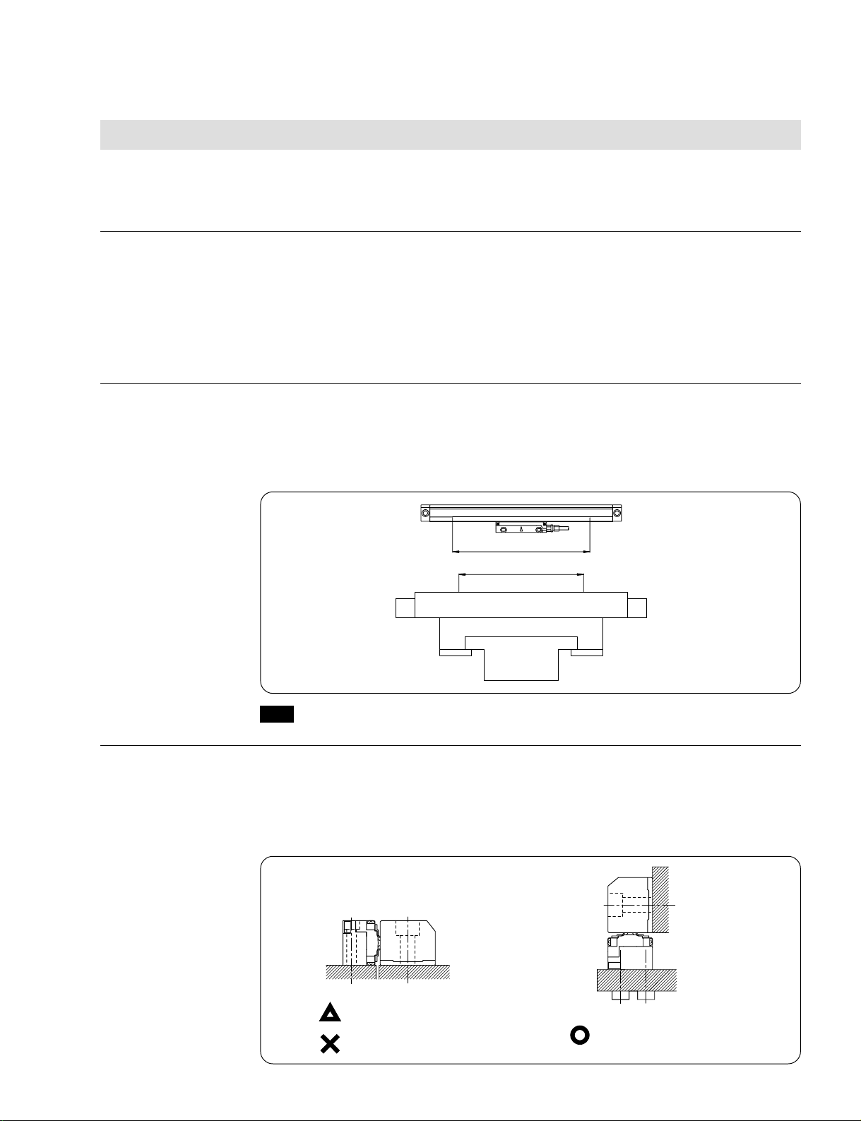
Installation Direction
Note
The scale will be damaged if it moves beyond the measuring length.
Although the traveling part of the scale unit is partially sealed, it is not completely
sealed off for structural reasons. When mounting the scale to the horizontal axis, install
it so that the opening points downwards. When mounting the scale to the vertical axis,
install it so that the opening points to the outside, away from the cutting tool.
Vertical installation
Horizontal installation
When it is impossible for debris to enter
Prohibited
When it is possible for debris to enter
Recommended installation direction
2-3
Page 16

Flatness and Parallelism of the Installation Surface
• The installation surface of the scale unit should be finished along its entire length to
finish symbol 6.3S or better and should be machined to a flatness of 0.05 mm
(0.002 in)/M (where M is the machine guide’s length).
If the scale overhangs the machine, it must be reinforced with a backplate made of
flat polished steel plate at least 12 mm (0.472 in) thick. Ensure that the installation
surface is free of gouges or flaws.
Flatness: 0.05 mm (0.002 in)/M
Overall scale length
• Design the installation surface so that the parallelism of the installation surface and
the scale in the vicinity of each scale mounting screw is 0.05 mm (0.002 in).
0.05
0.1
M
±0.3(0.012)
0
M: Machine guideway
50 mm (1.97 in)
0.1
0.05
M
21(0.827)
±0.3(0.012)
0.05
M
)
0.1
±0.5
±0.020
30.5
(1.20
Unit [mm(in)]
2-4
Parallelism: 0.05 mm (0.002 in)/M
50 mm (1.97 in)
Page 17

Designing the Scanning Unit Mounting Bracket
• The mounting bracket should be designed to have adequate rigidity relative to the
direction of travel.
Ensuring Sufficient Maintenance Space
• The scale unit must be removed when replacing the scanning or detector unit.
Therefore, ensure sufficient space for removing the scale unit.
Prohibited
Installation and removal space
Scanning unit
Detector unit
Installation and removal space
2-5
Page 18
2-3. Installation Procedure
The installation procedure for the scale unit is explained below. Note that the following
components must not be disassembled, as doing so may cause breakdowns.
[Do not Disassemble the Following]
• Mechanical and electrical components of the scanning unit
• Scale unit cable connectors
• Glass scale
The scale unit is composed of precision components, so applying undue force may
adversely affect the precision and life of the unit. Ensure that undue force is not exerted
on the scale unit during operation.
Support the main body of the scale unit and scanning unit during transport. Do not lift by
the cables or connectors.
2-3-1. Installing the Scale Unit
1. Checking the Flatness of the Scale Unit Installation Surface
• Check that the installation surface of the scale unit is finished along its entire length
to finish symbol 6.3S or better, and check that it has a flatness of 0.05 mm
(0.002 in)/M (where M is the machine guide’s length).
2. Installing the Support Bracket to the Scale
• A support bracket or brackets are supplied with scales which have a measuring
length of 520 mm (20.47 in) or more.
• Fixing nuts for the support brackets are inserted in the slit on the top face of the
scale. Install the support bracket or brackets using hexagonal socket head cap
screws (M3×6). Using a torque wrench, tighten to a torque of 1.5 N•m.
• Position the support bracket at the center of the scale. For scales with a measuring
length of 1020 mm (40.16 in) or more, position the support brackets so that the scale
is divided into equal parts.
• Either support bracket A or B can be selected.
2-6
Support bracket B
Support bracket A
3. Temporarily Securing the Scale Unit
• Move the movable machine part to roughly the center of the stroke and lightly secure
it with the supplied hexagonal socket head cap screws (M4×22).
4. Temporarily Securing the Support Bracket
• Temporarily secure the scale unit, then lightly secure the support bracket with the
supplied hexagonal socket head cap screws (M4×18).
Page 19

5. Checking the Parallelism of the Scale Unit
• Place a dial gauge on the top face of the scale unit and check its parallelism.
• The tolerance for the parallelism is 0.05 mm (0.002 in) in the vicinity of each scale
mounting screw. Adjust the scale unit so that the reading comes within this range.
50 mm (1.97 in)
Parallelism: 0.05 mm (0.002 in)/M
50 mm (1.97 in)
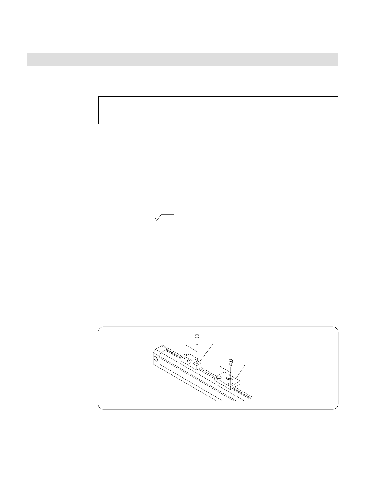
6. Securing the Scale Unit
• After checking the flatness and parallelism, tighten the hexagonal socket head cap
screws. Using a torque wrench, tighten to a torque of 2 N•m. Do not completely
tighten the hexagonal socket head cap screws one by one; rather, tighten all screws
evenly.
Hexagonal socket head cap screws M4×22
Support bracket
Hexagonal socket head cap screw M4×18
2-7
Page 20

2-3-2. Securing the Scanning Unit to the Mounting Bracket
When mounting the scanning unit into the mounting bracket, always make sure both
slider holders L and R are attached.
If slider holders L and R become detached, remount them.
When installing slider holders L and R for the first time, insert them into the scale
groove from the ends of the scale.
Inserting slider holders L and R into the scanning unit will determine the relative
positions of the scale and scanning unit.
Twisting the scanning unit while the slider holders are not in use may dislodge the
scanning unit dust seal from the dust seal guide groove. If the dust seal becomes
dislodged, it can be refitted without any problems. However, be careful not to dislodge
it during the installation work.
1. Checking Slider Holders L and R
• Check to make sure slider holders L and R are attached. If they have become
detached, remount them.
2-8
Slider holder L
Slider holder R
2. Checking for Installation Errors
• The mounting tolerance for the positions and height of the scale unit and scanning
unit is ±0.3 mm (0.012 in). If there is a gap between the scanning unit and the
mounting bracket, adjust with spacers or similar items. If the mounting bracket is too
high, switch to a lower mounting bracket.
Page 21

3. Securing the Scanning Unit
• With the scanning unit supported by slider holders L and R, slide it into the
installation position and secure it in place with the hexagonal socket head cap
screws (M4×22). Using a torque wrench, tighten to a torque of 2 N•m.
Mounting bracket
2-3-3. Removing the Slider Holders
1. Checking the Cap Screw Tightness
• Before removing the slider holders, double-check to make sure the scale and
scanning unit mounting cap screws are tightened.
2. Removing Slider Holders L and R
• Take out slider holders L and R from the ends of the scale.
• Trying to move the scale before removing the slider holders may damage the scale.
Pan-head machine
screw M3×5
Slider holder L
Slider holder R
2-9
Page 22

2-3-4. Cable Management
Managing Cables
• Manage cables so that they do not hinder machine operations or become entangled.
Handle cables carefully, as forceful pulling or repeated bending may damage them.
• The connector of the head cable has been waterproofed, but ensure that it is fitted in
a location where it is not exposed to chips or cutting fluid.
Minimum Cable Bending Radius
• Ensure that cables are arranged so that their bending radius tolerances are not
exceeded.
• The cable bending radii are as follows:
Head Cable
When the cable does not move during use ... Bending radius: 30 mm (1.18 in) or more
When the cable moves during use ................ Repeated bending not permitted
Connecting Cable
(Secure with a bending radius of 30 mm
(1.18 in) or more.)
When the cable does not move during use ... Bending radius: 50 mm (1.969 in) or more
When the cable moves during use ................ Bending radius: 100 mm (3.937 in) or more
Securing Cables
• Secure the head cable with cable clamps or similar items near the outlet. Also,
secure the connecting cable firmly so that it does not hinder machine operations or
become entangled.
Protecting the Connecting Cable Polarity Switch
• A polarity switch is attached to the connector that leads to the control unit. This
switch can be reversed to suit the reading direction of the scale.
Note
This switch can be operated during use, but doing so is very dangerous, as this reverses the
feedback signal.
Attach a protective cover to the polarity switch on the connector that leads to the control unit so
that it cannot be operated accidentally.
MR-20LS1
Polarity switch
FI-20-CV3
Polarity switch
2-10
39.3(1.55)
30(1.18)
Page 23

2-3-5. Precautions when the Scanning Unit is Connected to a Movable Component
Mounting the scale unit to a movable part and the scanning unit to a fixed part is ideal,
but if the reverse is necessary for structural reasons, the following points should be
noted:
Managing the Head Cable
• Secure the head cable and allow the connecting cable to bend.
• Secure the largest bending radius possible for the head cable.
• The allowable bending radius for the head cable is 30 mm (1.18 in) or more.
Managing the Connecting Cable
• Secure the connecting cable firmly so that it does not hinder machine operations or
become entangled. The cable getting caught on the operator or objects in the vicinity
presents a hazard. Furthermore, even if it does not appear so from the outside, the
internal core wire may be severed.
• The allowable bending radius of the connecting cable is 100 mm (3.937 in) or more.
The cable wires may be severed if subjected to repeated bending at radii smaller
than this.
Extending the Connecting Cable
• Do not extend the connecting cable to a length of more than 30 m (1181.10 in).
2-11
Page 24

2-3-6. Connection Example (Reference)
The drawing below shows an example of an interface.
When using a 26LS32, attach external resistance of 150 , since the IC does not have
an internally terminated resistor (Rt). The drawing below also shows the open circuit
alarm detection circuit.
Phase A
Phase B
Phase Tx
Scale side
26LS31
Tx
A
A
B
B
Tx
0.18 mm2 twisted
pair wire shield
Receiving side - example
5V
560Ω
560Ω
560Ω
560Ω
560Ω
560Ω
75115 or 26LS32
Rt
74LS86
5V
Rt
74LS86
5V
Rt
74LS86
Phase A
Phase B
Phase Tx
2-12
5V
GND
FG
Note
Use two core wires twisted together for each of the 5 V and GND power sources.
(Note)
Each power source
uses 2 lines.
Standard cable
5V
GND
FG
74LS86
CR time constant: about
10 µs is appropriate.
S
R
R
Open circuit alarm
Q
Reset
C
Page 25

2-4. Managing the Operating Environment
Installation Direction
• Although the traveling part of the scale unit is partially sealed, it is not completely
sealed off for structural reasons. When mounting the scale to the horizontal axis,
install it so that the opening points downwards. When mounting the scale to the
vertical axis, install it so that the opening points to the outside, away from the cutting
tool.
Horizontal installation
When it is impossible for debris to enter
Prohibited
When it is possible for debris to enter
Vertical installation
Recommended installation direction
Protective Cover
Scale unit cover
Sealed part
Scanning unit
Spattered
cutting fluid
• Attach a protective cover with the necessary strength if the scale is installed in a
location where the operator may place his elbows or legs.
• Preferably, choose a mounting location where the scale will not be exposed to chips
or cutting fluid. If that is impossible, attach an appropriate cover.
Scale
Scale unit cover
Table
Sealed part
Scanning unit
Spattered
cutting fluid
Scale
Table
Prohibited
2-13
Page 26
2-5. Air Purge
The scale bracket is fitted with standard M5 tap holes on both sides to allow air intake.
If the scale unit is to be used in the environments listed below, harmful effects can be
reduced by blowing clean air into the unit.
• Dusty locations
• Highly humid locations
• Locations where changes in temperature and humidity give rise to condensation
As the efficacy of introducing air depends on the service conditions, do so only after
verifying the effectiveness.
Air Tubing Route and Equipment Configuration
• Take into consideration the tubing route and other factors when choosing between
the left and right air intake ports.
Note that the air intake ports are capped with M5×5 hexagonal socket head locking
screws, which should be removed before use.
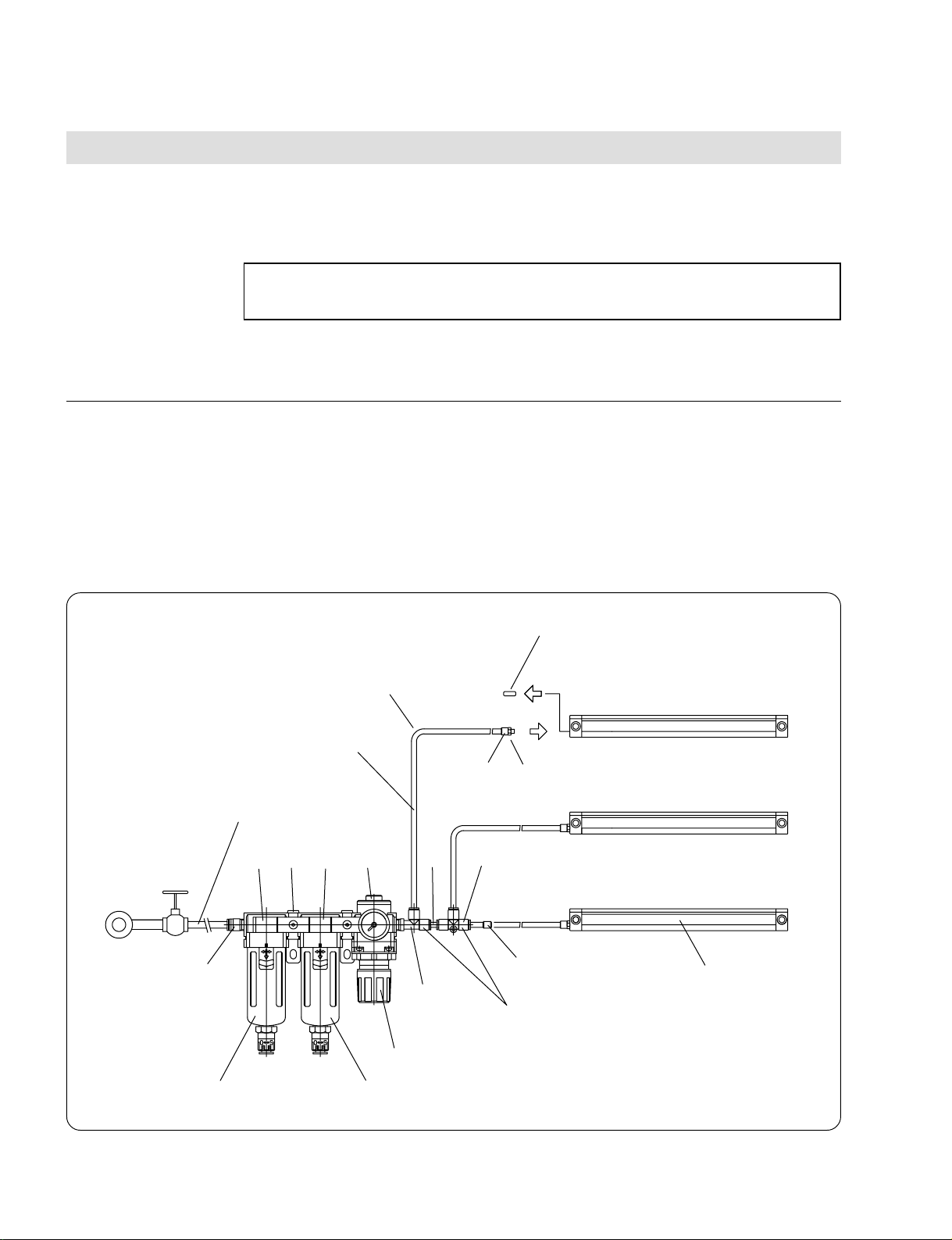
• Prepare the equipment and tubing as shown in the figure below to allow air to be
introduced into the scale unit.
Tube, bending radius 15 mm(0.59 in) or more
Polyurethane tube, outer diameter 6 mm(0.236 in)
inner diameter 4 mm(0.157 in)
Nylon tube, outer diameter 8 mm(0.315 in)
2
3
Air pressure source
1
4
5
M5×5 hexagonal socket head locking screws
Hose nipple
!º
8
7
9
6
Distributor
Pressure-reducing valve
Scale unit
2-14
Filter [nominal filtration rating
5 µm(0.000197 in)]
Mist separator [nominal filtration rating
0.3 µm(0.0000118 in)]
Page 27

• The air supply unit and fittings should be provided by the customer.
The tables below provide standard equipment specifications and component parts
(manufacturers) for reference.
Specifications
Item Specification
Proof pressure 1.5 MPa
Maximum service pressure 1020 kPa
Set pressure range 20 to 200 kPa
Service fluid Air
Ambient temperature and service fluid temperature –5 to +60°C (33 to 140°F)
(must not freeze)
Nominal filtration rating Air filter: 5 µm (0.000197 in)
Mist separator: 0.3 µm (0.0000118 in)
Pressure gauge connection diameter 2-Rc (PT) 1/8
Tubing connection diameter IN side: Outer diameter of tube 8 mm
(0.315 in) (one location)
OUT side: Outer diameter of tube
6 mm (0.236 in) (three locations)
Auto drain differential pressure 150 to 1020 kPa
Component Parts
Part No. Model No. Name Quantity Manufacturer
1 AF3000-02C Air filter 1 SMC
(nominal filtration rating: 5 µm (0.000197 in))
2 AFM3000-02C Mist separator 1 SMC
(nominal filtration rating: 0.3 µm (0.0000118 in))
3 AR3000-02G-1 Pressure-reducing valve 1 SMC
4 Y30L Spacer assembly with L-shaped bracket 2 SMC
5 KQH08-02S Half-union 1 SMC
6 KQY06-02S Service cheese union 1 SMC
7 KQT06-00 Cheese 1 SMC
8 KQN06-99 Nipple 1 SMC
9 KQP-06 Plug 3 SMC
10 M-5H6 Hose nipple 3 SMC
2-15
Page 28

Tubing
0
10
20
30
40
50
60
70
80
012345678910
Tube Installation
Ensure a tube bending radius of 15 mm (0.59 in) or more, and do not allow the tube to
bend sharply. Also, when installing tubes in parallel in electrical, hydraulic or other
ducts, make sure that the movement of the duct does not cause the tube to collapse.
Tube Length
To match the air intake pressure into each scale unit, always ensure that the tubes from
the air supply unit distributors to the intake ports are the same length.
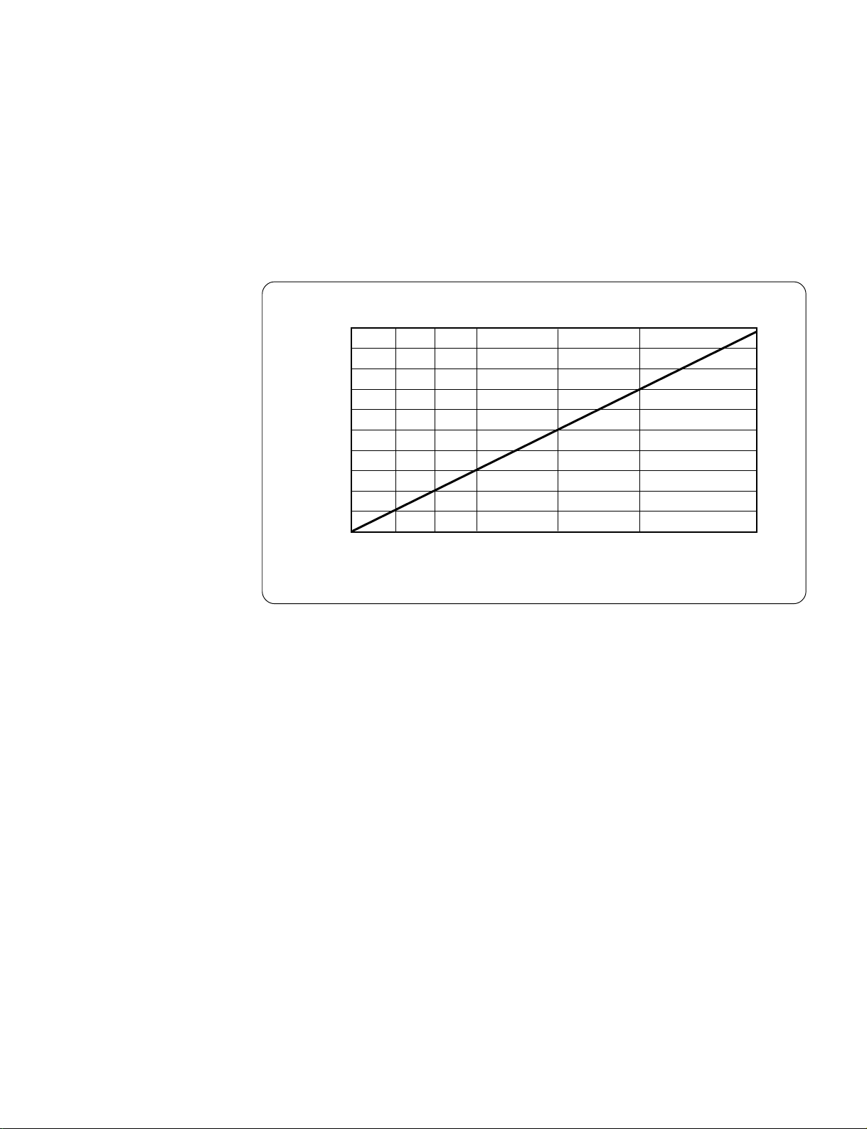
Pressure-Reducing Valve Set Pressure and Tube Length
If the intake air pressure into each scale unit is around 20±10 kPa, the humidity of the
air in the scale unit can be kept low. However, the length of the tube precludes the use
of the pressure-reducing valve to obtain an intake air pressure of 20±10 kPa.
Determine the set pressure for the pressure-reducing valve with reference to the
diagram below, “Pressure-Reducing Valve Set Pressure and Tube Length”.
Pressure-Reducing Valve Set Pressure
(kPa)
Polyurethane tubing length (outer dia. 6 mm (0.236 in), inner dia. 4 mm (0.157 in)
Pressure-Reducing Valve Set Pressure and Tube Length
This diagram shows the relationship between the set pressure for the pressurereducing valve and the tube length for an intake air pressure of 20 kPa.
Tube length here means the length from the distributor of the air supply unit to the
intake port of the scale unit.
When the intake air pressure is 20 kPa, the amount of air consumed for each unit is
2-16
approximately 30 Nr/min.
Flushing the Tubing
Using the air source, flush the air supply unit connection and the inlet portion leading
into the scale. This cleans the tubing, prevents debris from getting caught in the
machinery, and also serves as a check for the tubing.
Page 29
Air Pressure Source
When using a compressor as the air pressure source, select an appropriate
compressor in consideration of the volume of air to be consumed (approx. 30 Nr/min.
per unit). The following diagram, “Delivery Capacity and Rated Output”, may provide
some assistance in choosing the compressor, but note that specifications vary between
different models.
Delivery Capacity
(Nr/min.)
1000
800
600
400
200
0
0 1 2 3 5 7.5 10
Rated Output (PS)
Delivery Capacity and Rated Output
2-17
Page 30

Page 31

Chapter 3 Maintenance
3-1. Start-up Inspection
Checking for Open Circuits
The scanning unit is normally connected to the control unit by a connecting cable
through the cable (head cable) from the scanning unit. Both the head cable and
connecting cable must be checked if there is an open circuit. Shake the movable parts
of the head cable and connecting cable and confirm that the open circuit alarm is not
displayed on the control unit. If it is, the severed cable unit must be repaired. It is
extremely dangerous to continue operations without repairing the cable; immediately
stop the machine and contact your Sony Manufacturing Systems Corporation
distributor.
While checking the head cable, pay close attention to the connection with the scanning
unit and the junction connector. Also, when using a conduit connecting cable, check
very carefully as there may be open circuits caused by microscopic chips.
Checking for Dust Lip Wear
Look at the underside of the scale, and check to see if the edge of the dust lip is worn.
If it is, the scale glass and inside detector part must be cleaned and the dust lip
replaced. Contact your Sony Manufacturing Systems Corporation distributor.
Checking for Odd Noises
Slowly move the machine and listen to see if any odd noises occur. If so, the scale main
body and scanning unit may be in contact. Continuing operation in this condition may
lead to major breakdowns, so stop the machine immediately and contact your Sony
Manufacturing Systems Corporation distributor.
Strictly Enforce Cleaning
Ensure that chips are cleaned up before starting work and at the end of work each day
to prevent them from building up around the scale. Otherwise, chip buildup may prevent
the scale from sliding and cause breakdowns. Avoid using air guns or similar
devices for cleaning, because while the traveling part of the scale unit is sealed, it is
not completely sealed off for structural reasons. Use of an air gun may cause chips or
other debris to penetrate into the scale and cause breakdowns.
3-2. Regular Inspections
Presence of Condensation
If mist, condensation, dust or coolant (water-miscible cutting fluid) are present on the
dust lip of the scale unit, strengthen the cover and supply air to the unit.
3-1
Page 32

Page 33

Chapter 4 Specifications
4-1. General Specifications and Performance Specifications
General Specifications
Item Specification
Service temperature range 0°C to +45°C (32°F to 113°F)
Storage temperature range –10°C to +60°C (14°F to 141°F)
Service humidity range Relative humidity 30% to 90% (no condensation)
Rate of change of temperature, humidity A rate that does not cause condensation
Service environment No corrosive gas
Vibration resistance 68.6 m/s2 or less (30 to 1000 Hz for 30 min.)
Impact resistance 147 m/s2 or less (11 ms X, Y, Z directions, three times each)
Performance Specifications
Item Specification
Detection system Optical Moiré fringe detection system (transmission model)
Output system Two-phase signal (Phase A, Phase B), Line driver output
Light source and light-receiving device Infrared light-emitting diode, photodiode
Measuring length [mm(inch)] 20 lengths: 70(2.76), 120(4.72), 170(6.69), 220(8.66), 270(10.63),
320(12.60), 370(14.57), 420(16.54), 470(18.50), 520(20.47),
570(22.44), 620(24.41), 670(26.38), 720(28.35), 770(30.31),
820(32.28), 920(36.22), 1020(40.16), 1140(44.88), 1240(48.82)
Maximum response speed Resolution: 0.05 µm, t = 0.16 µs, 12 m/min.
t = 0.3 µs, 6 m/min.
Resolution: 0.1 µm, t = 0.16 µs, 24 m/min.
t = 0.3 µs, 12 m/min.
Zero point detection speed 0.05 µm 0.01 to 0.05 m/min
0.1 µm 0.01 to 0.2 m/min
Scale resolution 0.05 µm (0.00000195 in), 0.1 µm (0.0000039 in)
Glass grating pitch 16 µm (0.00063 in)
Scale zero point One point in the center for a measuring length of 70 mm (2.756 in),
otherwise, two points at the left and right ends inside the measuring
length.
Scale precision Measuring length
70(2.76) to 620(24.41) mm(in): ±2 µm
670(26.38) to 1240(48.82) mm(in): ±3 µm
Allowable mounting parallelism 0.05 mm (0.00197 in)
Precision proof temperature 20°C (68°F)
Glass thermal expansion coefficient (8.8 ± 1) ×10
Protection class IP53 (when used in accordance with the instruction manual)
Power supply and current consumption DC +5 V ±5%, 250 mA
-6
/°C
4-1
Page 34

4-2. Resolution and Response Speeds
Relationship between Resolution and Maximum Response Speed
Model Resolution Min. Phase Difference Grating Pitch Max. Response Speed
SH11-B1A 0.05 µm 0.16 µs 16 µm 12 m/min
SH11-B1B 0.05 µm 0.3 µs 16 µm 6 m/min
SH11-C1A 0.1 µm 0.16 µs 16 µm 24 m/min
SH11-C1B 0.1 µm 0.3 µs 16 µm 12 m/min
Relationship between Resolution and Zero Point Detection Speed
Model Resolution Min. Phase Difference Zero Point Detection Speed Range
SH11-B1A 0.05 µm 0.16 µs 0.01 to 0.05 m/min
SH11-B1B 0.05 µm 0.3 µs 0.01 to 0.05 m/min
SH11-C1A 0.1 µm 0.16 µs 0.01 to 0.2 m/min
SH11-C1B 0.1 µm 0.3 µs 0.01 to 0.2 m/min
Phase A
Phase B
tttt tttt
t = 10 to 15 µs
Time
Example of output waveform (Symbol: C1, t = 0.3 µs)
• Connect to a control unit able to read the
minimum phase difference (t).
• Set the minimum phase difference able to be read
by the control unit so that X < t when the (X) scale
minimum phase difference is set to (t).
• The A-phase and B-phase output signals are
output at intervals. The figure at left shows an
example when these signals are output at a fixed
speed exceeding the zero point detection speed.
4-2
Page 35

4-3. Electrical Characteristics
1. Output Waveform
Normal operation
Fault or
power on
(high impedance)
Phase A
Phase B
Zero point
A
A
Note
rr
•
r = P/4 (
B
rr
• The phase relationship between the zero
rr
r = scale resolution)
rr
point signal and phases A and B is not
B
specified.
• Perform zero point detection in a fixed
rr rr
P
direction.
• As shown in the figure at left, the output is
high impedance when the cable is severed
or a fault occurs in the scale. Therefore,
be sure to connect to a circuit that can
receive the signal at the control unit.
Z
Z
Te: 0.5 s Tf: 10 ms
Zero point position
Scale unit
2. Output Format
Scanning unit
AM26LS31 or equivalent
The above figure shows an output waveform when the scanning unit is
secured in place and the scale unit is moved from left to right.
A
A
B
B
IOH: –30 mA min
Z
Z
IOL: 30 mA max
VOH: +2.5 V min
OH
(at I
= –30 mA)
VOL: +0.5 V max
OL
(at I
= 30 mA)
4-3
Page 36

4-4. Cable Specifications
A connecting cable is used to join the scale unit and the control unit.
Whether or not to use a conduit connecting cable is specified by the shape of the
terminal that leads to the control unit.
When used in an environment where there is a concern that the cable segment might
be damaged, choose a conduit cable.
The connector has a dust-proof, drip-proof construction (except for the connector that
leads to the control unit).
The connector that leads to the control unit is fitted with a polarity switch, which can be
used to reverse the scale reading direction. This switch can be operated during use, but
doing so is extremely dangerous as it reverses the feedback signal. Attach a cover or
similar device to the polarity switch on the connector that leads to the control unit to
prevent against accidental operation.
Connecting Cable
Model
Cable length MR connector Mini Dsub connector Frayed tip
Conduit cable Conduit cable No conduit cable No conduit cable
2 m (78.7 in) CR1-02MC — CR1-02DC —
3 m (118.1 in) CR1-03MC — CR1-03DC —
5 m (196.9 in) CR1-05MC CR1-05DC — CR1-05NN
7 m (275.6 in) CR1-07MC CR1-07DC ——
10 m (393.7 in) CR1-10MC CR1-10DC — CR1-10NN
15 m (590.6 in) CR1-15MC CR1-15DC ——
20 m (787.4 in) CR1-20MC CR1-20DC — CR1-20NN
30 m (1181.1 in) CR1-30MC CR1-30DC — CR1-30NN
4-4
Page 37

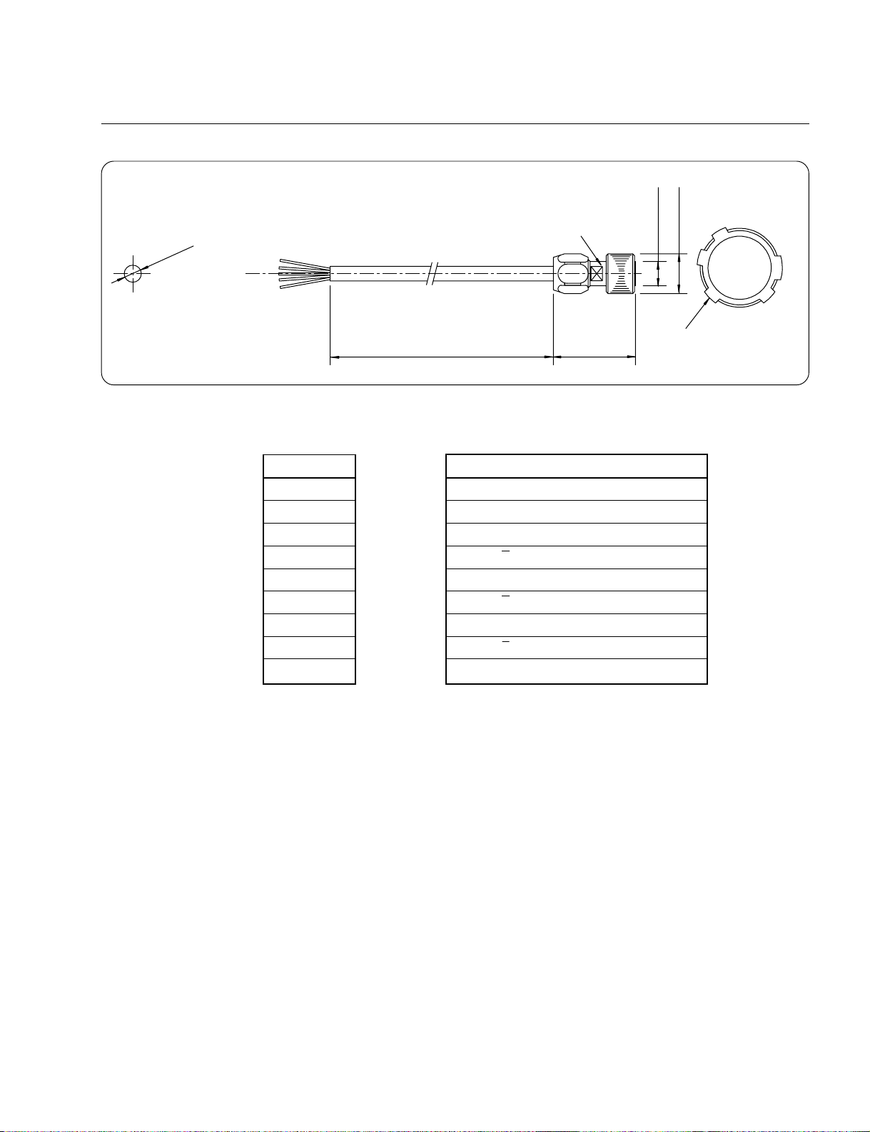
Model CR1-
7
1
!£
8
@º
!¢
19.5(0.768)
MR-20F
MR-20LS1
39.3(1.55)
48(1.89)
ø10(0.394)
ø12(0.472)
ø19.6(0.772)
1
2
3
4
5
6
7
8
9
!º
!¡
!™
43.5(1.71)
Connector pin configuration
17(0.669)
Cable length
Polarity switch
Conduit cable
Connector: HR10WT 12P-12S
MC (MR connector, Conduit)
Wiring Chart
Wire Color MR-20F Pin No. Signal Name HR10WT Pin No.
Gray, purple 1, 2, 3 GND 6, 11
Shield 20 FG 7
Red 16 Phase A 2*
Orange 17 Phase A 8*
Yellow 18 Phase B 3
Green 19 Phase B 9
Black 14 Phase Z 4
Brown 15 Phase Z 10 (Zero point)
Blue, white 4, 5, 6 +5 V 5, 12
Unit [mm(in)]
*
This chart applies when the polarity switch on the connector is set to [I].
When the polarity switch is set to [II], phases A and A are substituted.
4-5
Page 38

Model CR1-
DC (Mini Dsub connector, Conduit)
Crimped terminal ø6(0.236)
FI40-2015S
@º
!º
!•
!§
!¢
!™
1
12(0.472)
Model CR1-
FI40-2015S
@º
!º
!•
!§
!¢
!™
1
12(0.472)
FI-20-CV3
500(19.69)
Polarity switch
Earth wire
ø18
(0.709)
30(1.18)
42(1.65) 43.5(1.71)
DC (Mini Dsub connector, No conduit)
FI-20-CV3
Cable
length
seal
2000(78.74)
500(19.69)
Conduit securing nut
22(0.866)
Cable length
Polarity switch
Earth wire
30(1.18)
42(1.65)
Cable length
Connector: HR10WT 12P-12S
ø12
(0.472)
Connector pin configuration
Crimped terminal ø6(0.236)
Connector: HR10WT 12P-12S
ø12
43.5(1.71)
Connector pin configuration
ø19.6
(0.472)
ø19.6
(0.772)
(0.772)
7
8
6
!™
5
!º
1
!¡
4
2
3
Unit [mm(in)]
7
8
6
!™
5
!º
!¡
4
2
3
9
9
1
4-6
Wiring Chart
Wire Color FI140-2015S Pin No. Signal Name HR10WT Pin No.
Gray, purple 12, 14, 16 GND 6, 11
Shield — FG 7 (Earth wire)
Red 1 Phase A 2*
Orange 2 Phase A 8*
Yellow 3 Phase B 3
Green 4 Phase B 9
Black 5 Phase Z 4 (Zero point)
Brown 6 Phase Z 10
Blue, white 9, 18, 20 +5 V 5, 12
*
This chart applies when the polarity switch on the connector is set to [I].
When the polarity switch is set to [II], phases A and A are substituted.
Unit [mm(in)]
Page 39
Model CR1-
1
2
3
4
5
6
7
8
9
!º
!¡
!™
ø12(0.472)
ø19.6(0.772)
43.5(1.71)
Connector pin configuration
Cable length
Connector: HR10WT 12P-12S
ø7(0.276)
NN (Frayed tip, No conduit)
Wiring Chart
Wire Color Signal Name HR10WT Pin No.
Gray, purple GND 6, 11
Shield FG 7
Red Phase A 2
Orange Phase A 8
Yellow Phase B 3
Green Phase B 9
Black Phase Z 4 (Zero point)
Brown Phase Z 10
Blue, white +5 V 5, 12
......................
......................
......................
......................
......................
......................
......................
......................
......................
Unit [mm(in)]
4-7
Page 40

Precautions When Using the Connecting Cable
• Protecting the Connecting Cable Polarity Switch
A polarity switch is attached to the connector which leads to the control unit. This
switch can be reversed to suit the reading direction of the scale.
Note
This switch can be operated during use, but doing so is very dangerous, as this reverses the
feedback signal.
Attach a protective cover to the polarity switch on the connector that leads to the control unit so
that it cannot be operated accidentally.
• Minimum Connecting Cable Bending Radius
The connecting cable bending radii are as follows:
When the cable does not move during use ...... Bending radius: 50 mm (1.97 in) or more
When the cable moves during use .................. Bending radius: 100 mm (3.94 in) or more
• Extending the Connecting Cable
Do not extend the connecting cable to a length of more than 30 m (1181.1 in).
4-8
Page 41

Chapter 5 Appendix
5-1. Model Summary
Scale Unit (Resolution: 0.05 µm (0.00000195 in), minimum phase difference: 0.16 µs)
Measuring length Model Measuring length Model
70 (2.76) SH11-007B1A2 670 (26.38) SH11-067B1A3
120 (4.72) SH11-012B1A2 720 (28.35) SH11-072B1A3
170 (6.69) SH11-017B1A2 770 (30.31) SH11-077B1A3
220 (8.66) SH11-022B1A2 820 (32.28) SH11-082B1A3
270 (10.63) SH11-027B1A2 920 (36.22) SH11-092B1A3
320 (12.60) SH11-032B1A2 1020 (40.16) SH11-102B1A3
370 (14.57) SH11-037B1A2 1140 (44.88) SH11-114B1A3
420 (16.54) SH11-042B1A2 1240 (48.82) SH11-124B1A3
470 (18.50) SH11-047B1A2
520 (20.47) SH11-052B1A2
570 (22.44) SH11-057B1A2
620 (24.41) SH11-062B1A2
Scale Unit (Resolution: 0.05 µm (0.00000195 in), minimum phase difference: 0.3 µs)
Measuring length Model Measuring length Model
70 (2.76) SH11-007B1B2 670 (26.38) SH11-067B1B3
120 (4.72) SH11-012B1B2 720 (28.35) SH11-072B1B3
170 (6.69) SH11-017B1B2 770 (30.31) SH11-077B1B3
220 (8.66) SH11-022B1B2 820 (32.28) SH11-082B1B3
270 (10.63) SH11-027B1B2 920 (36.22) SH11-092B1B3
320 (12.60) SH11-032B1B2 1020 (40.16) SH11-102B1B3
370 (14.57) SH11-037B1B2 1140 (44.88) SH11-114B1B3
420 (16.54) SH11-042B1B2 1240 (48.82) SH11-124B1B3
470 (18.50) SH11-047B1B2
520 (20.47) SH11-052B1B2
570 (22.44) SH11-057B1B2
620 (24.41) SH11-062B1B2
Unit [mm (in)]
Unit [mm (in)]
Scale Unit (Resolution: 0.1 µm (0.0000039 in), minimum phase difference: 0.16 µs)
Measuring length Model Measuring length Model
70 (2.76) SH11-007C1A2 670 (26.38) SH11-067C1A3
120 (4.72) SH11-012C1A2 720 (28.35) SH11-072C1A3
170 (6.69) SH11-017C1A2 770 (30.31) SH11-077C1A3
220 (8.66) SH11-022C1A2 820 (32.28) SH11-082C1A3
270 (10.63) SH11-027C1A2 920 (36.22) SH11-092C1A3
320 (12.60) SH11-032C1A2 1020 (40.16) SH11-102C1A3
370 (14.57) SH11-037C1A2 1140 (44.88) SH11-114C1A3
420 (16.54) SH11-042C1A2 1240 (48.82) SH11-124C1A3
470 (18.50) SH11-047C1A2
520 (20.47) SH11-052C1A2
570 (22.44) SH11-057C1A2
620 (24.41) SH11-062C1A2
Scale Unit (Resolution: 0.1 µm (0.0000039 in), minimum phase difference: 0.3 µs)
Measuring length Model Measuring length Model
70 (2.76) SH11-007C1B2 670 (26.38) SH11-067C1B3
120 (4.72) SH11-012C1B2 720 (28.35) SH11-072C1B3
170 (6.69) SH11-017C1B2 770 (30.31) SH11-077C1B3
220 (8.66) SH11-022C1B2 820 (32.28) SH11-082C1B3
270 (10.63) SH11-027C1B2 920 (36.22) SH11-092C1B3
320 (12.60) SH11-032C1B2 1020 (40.16) SH11-102C1B3
370 (14.57) SH11-037C1B2 1140 (44.88) SH11-114C1B3
420 (16.54) SH11-042C1B2 1240 (48.82) SH11-124C1B3
470 (18.50) SH11-047C1B2
520 (20.47) SH11-052C1B2
570 (22.44) SH11-057C1B2
620 (24.41) SH11-062C1B2
Unit [mm (in)]
Unit [mm (in)]
5-1
Page 42

Connecting Cable (Connector, Conduit)
Cable length MR connector Mini Dsub connector Frayed tip
2 m (78.7 in) CR1-02MC — CR1-02DC —
3 m (118.1 in) CR1-03MC — CR1-03DC —
5 m (196.9 in) CR1-05MC CR1-05DC — CR1-05NN
7 m (275.6 in) CR1-07MC CR1-07DC ——
10 m (393.7 in) CR1-10MC CR1-10DC — CR1-10NN
15 m (590.6 in) CR1-15MC CR1-15DC ——
20 m (787.4 in) CR1-20MC CR1-20DC — CR1-20NN
30 m (1181.1 in) CR1-30MC CR1-30DC — CR1-30NN
Model
Conduit cable Conduit cable No conduit cable No conduit cable
5-2
Page 43

このマニュアルに記載されている事柄の著作権は当社にあ
り、説明内容は機器購入者の使用を目的としています。
したがって、当社の許可なしに無断で複写したり、説明内
容(操作、保守など)と異なる目的で本マニュアルを使用
することを禁止します。
The material contained in this manual consists of
information that is the property of Sony Manufacturing
Systems Corporation and is intended solely for use by
the purchasers of the equipment described in this
manual.
Sony Manufacturing Systems Corporation expressly
prohibits the duplication of any portion of this manual
or the use thereof for any purpose other than the
operation or maintenance of the equipment described
in this manual without the express written permission
of Sony Manufacturing Systems Corporation.
Le matériel contenu dans ce manuel consiste en
informations qui sont la propriété de Sony
Manufacturing Systems Corporation et sont destinées
exclusivement à l'usage des acquéreurs de
l'équipement décrit dans ce manuel.
Sony Manufacturing Systems Corporation interdit
formellement la copie de quelque partie que ce soit de
ce manuel ou son emploi pour tout autre but que des
opérations ou entretiens de l'équipement à moins
d'une permission écrite de Sony Manufacturing
Systems Corporation.
Die in dieser Anleitung enthaltenen Informationen
sind Eigentum von Sony Manufacturing Systems
Corporation und sind ausschließlich für den Gebrauch
durch den Käufer der in dieser Anleitung
beschriebenen Ausrüstung bestimmt.
Sony Manufacturing Systems Corporation untersagt
ausdrücklich die Vervielfältigung jeglicher Teile dieser
Anleitung oder den Gebrauch derselben für
irgendeinen anderen Zweck als die Bedienung oder
Wartung der in dieser Anleitung beschriebenen
Ausrüstung ohne ausdrückliche schriftliche Erlaubnis
von Sony Manufacturing Systems Corporation.
Page 44

Sony Manufacturing Systems Corporation
Isehara Plant
45 Suzukawa, Isehara-shi, Kanagawa 259-1146 Japan TEL: +81 (463) 92-7971 FAX: +81 (463) 92-7978
Sony Precision Technology America, Inc.
20381 Hermana Circle, Lake Forest, CA 92630, U.S.A. TEL: (949) 770-8400 FAX: (949) 770-8408
Sony Precision Technology Europe GmbH
Heinrich-Hertz-Strasse 1 , 70327 Stuttgart, Germany TEL: (0711) 5858-777 FAX: (0711) 580715
http://www.sonysms.co.jp/
Sony Manufacturing Systems Corporation
SH11 Series
3-861-878-14
1-10 Kiyoku-cho, Kuki-shi, Saitama 346-0035 Japan
2004.4
Printed in Japan
©1997 Sony Manufacturing Systems Corporation
 Loading...