

Page 1
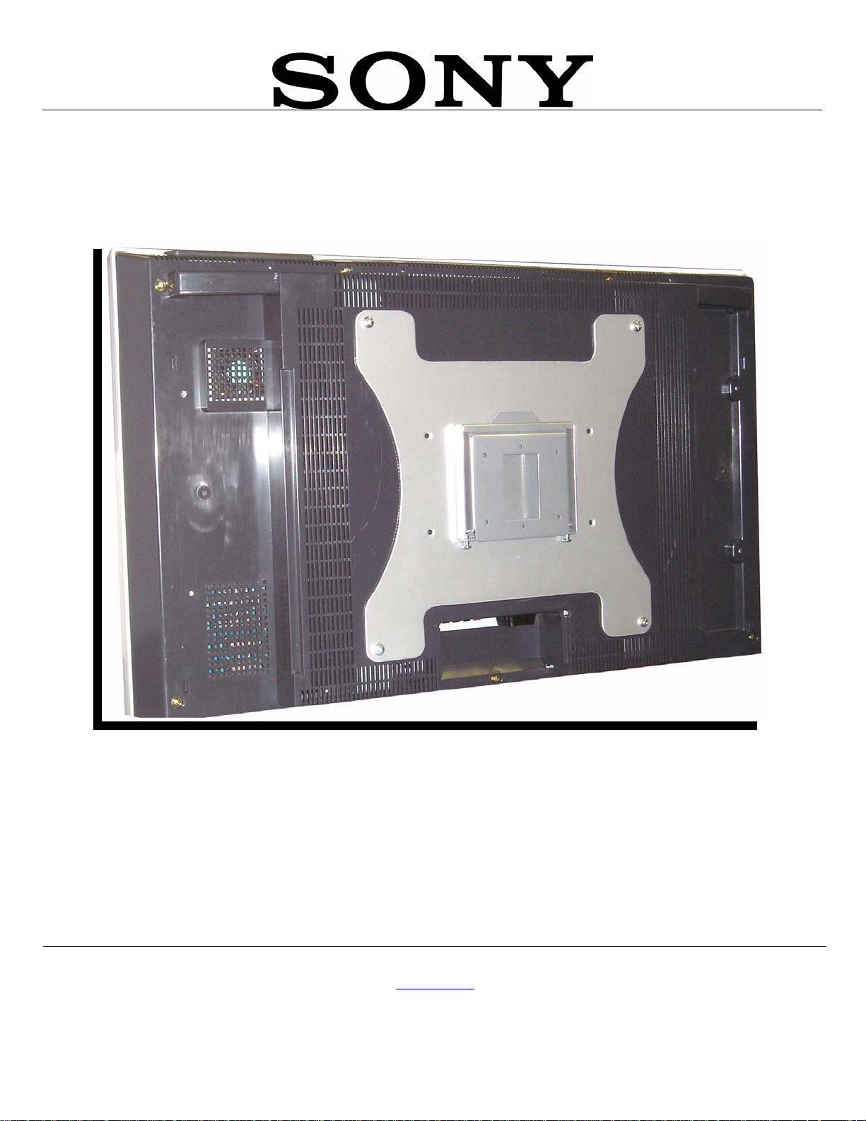
INSTALLATION MANUAL
IN-SFM2.R1
SFM2
Sony Electronics, Inc.
16540 West Bernardo Drive
San Diego, CA 92127
www.sony.com
Page 2

SFM2
Table of Contents
WARNING STATEMENTS....................................................................................................................................... - 3 -
PARTS LIST ............................................................................................................................................................. - 4 -
INSTALLATION TOOLS .......................................................................................................................................... - 4 -
INSTALLATION PROCEDURES .............................................................................................................................. - 5 -
SINGLE STUD INSTALLATION .............................................................................................................................. - 5 -
SOLID STRUCTURE INSTALLATION ..................................................................................................................... - 6 -
ATTACHING THE ADAPTER PLATE AND THE BACKPLATE COVER ................................................................. - 7 -
ATTACHING THE ADAPTER PLATE /BACKPLATE COVER TO THE DISPLAY ................................................... - 9 -
ATTACHING THE DISPLAY TO THE BACKPLATE ............................................................................................. - 10 -
TECHNICAL SPECIFICATIONS ............................................................................................................................. - 11 -
WARRANTY ........................................................................................................................................................... - 12 -
CUSTOMER SUPPORT ......................................................................................................................................... - 12 -
NOTES ................................................................................................................................................................... - 12 -
Page - 2 - Installation Manual
Page 3

Warning Statements
WARNING:
WARNING:
WARNING:
THE WALL STRUCTURE MUST BE CAPABLE OF SUPPORTING AT LEAST FIVE (5) TIMES THE
WEIGHT OF THE DISPLAY. IF NOT, THE WALL STRUCTURE MUST BE REINFORCED. PROPER
INSTALLATION PROCEDURE BY A QUALIFIED SERVICE TECHNICIAN, AS OUTLINED IN THE
INSTALLATION INSTRUCTIONS, MUST BE ADHERED TO. FAILURE TO DO SO COULD RESULT
IN SERIOUS PERSONAL INJURY, OR EVEN DEATH.
SAFETY MEASURES MUST BE PRACTICED AT ALL TIMES DURING THE INSTALLATION OF
THIS PRODUCT. USE PROPER SAFETY GEAR AND TOOLS FOR THE INSTALLATION
PROCEDURE TO PREVENT PERSONAL INJURY.
PRIOR TO THE INSTALLATION OF THIS PRODUCT, THE INSTALLATION INSTRUCTIONS
SHOULD BE READ AND COMPLETELY UNDERSTOOD. THE INSTALLATION INSTRUCTIONS
MUST BE READ TO PREVENT PERSONAL INJURY AND PROPERTY DAMAGE. KEEP THESE
INSTALLATION INSTRUCTIONS IN AN EASILY ACCESSIBLE LOCATION FOR FUTURE
REFERENCE.
Indicates that the power plug is to be
disconnected from the power outlet.
Safety precautions must be taken at all
Contact Sony Electronics with any
questions.
times.
Warning and Caution statements.
Do not install on a structure that is prone to vibration, movement or chance of impact. Failure to
do so could result in damage to the display and/or damage to the mounting surface.
Do not install near heater, fireplace, direct sunlight, air conditioning or any other source of direct
heat energy. Failure to do so may result in damage to the display and could increase the risk of
fire.
At least two qualified people should perform the installation procedure. Injury and/or damage can
result from dropping or mishandling the plasma display.
Recommended mounting surfaces: wooden studs and solid-flat concrete. If the mount is to be
installed on any surface other than wooden studs, use suitable hardware (which is commercially
available).
SFM2
Installation Manual Page - 3 -
Page 4
SFM2
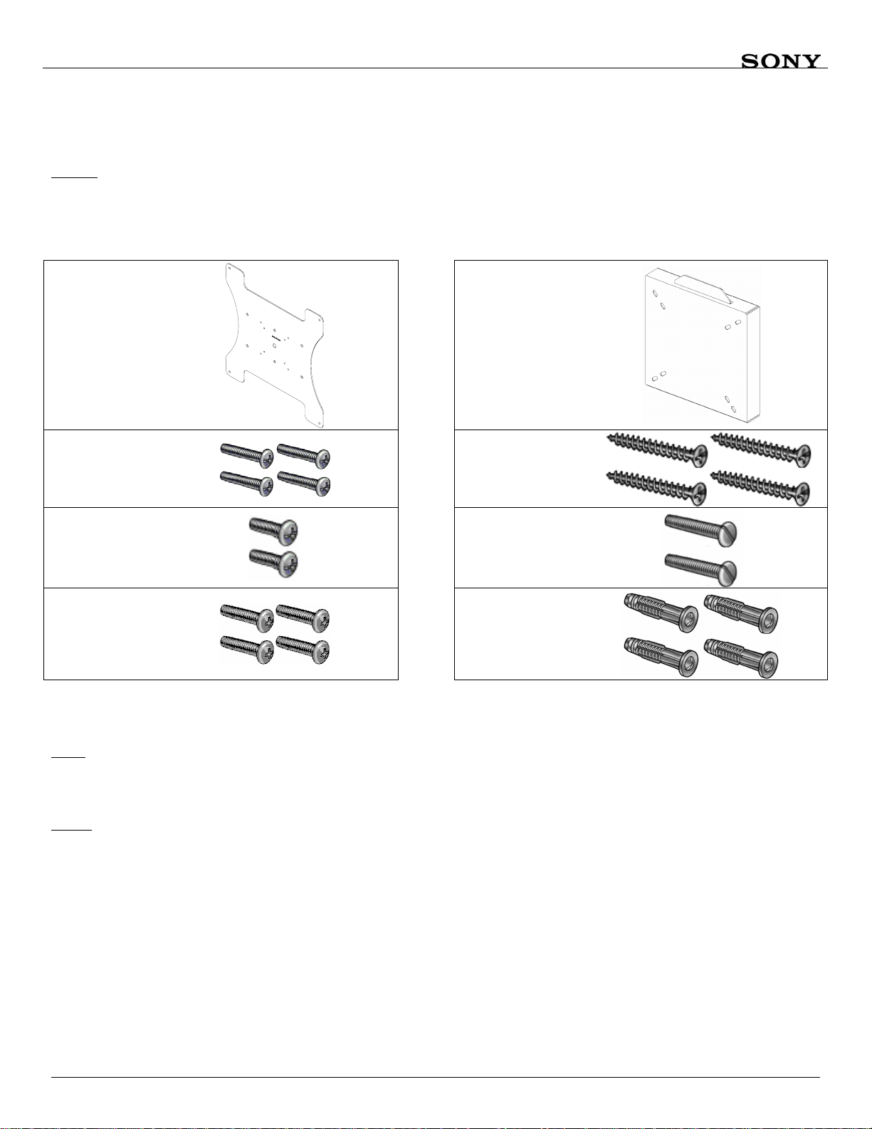
Parts List
NOTE: This wall mount is shipped with all proper installation hardware and components. Make sure that
none of these parts are missing and/or damaged before beginning installation. If there are parts
missing and/or damaged, please stop the installation and contact Sony Electronics
(877) 350-3477.
Adapter Plate
(Qty 1)
M4 x 10mm
Phillips Pan
Head Screw
(Qty 4)
M6 x 12mm
Security Screws
(Qty 2)
M6 x 10mm
Phillips Head
Screws (Qty 4)
Ultra Flat Mount
#10 x 1-1/4” Wood
Screws (Qty 4)
6/32” x 1” Slotted
Screw (Qty 2)
#10 Anchors
(Qty 1)
(Qty 4)
For use with the following Sony models:
SONY
FWD-32LX1
FWD-32LX1R
NOTE: Prior to installing the SFM2, the quick release sleeves (located on the back of the display) must
be removed. After removing them, please store them in a safe location for possible future re-use.
Installation Tools
Phillips Head Screw Driver Portable Drill ¼” Drill Bit Level (Supplied)
Soft Material/ Blanket Pencil Tape Measure Wrench with ½” Drive Socket
Page - 4 - Installation Manual
Page 5

SFM2
Installation Procedures
Check that you have all the hardware listed in the parts list (Page 5). If any of the hardware described is
missing, do not continue. Contact Sony Electronics immediately at (877) 350-3477.
Separate the plates and choose the location for the monitor and follow any precautions listed in the LCD
owners’ manual.
Single Stud Installation
1. For single wood studs, use the two middle mounting points found on the back plate (Figure 1).
2. Locate the center of the wood stud behind the wall, mark the height and desired location.
3. Drill two 1/4 " pilot holes on the marked wall.
4. Secure the back plate to the center of the wood stud by using two (2) #10 wood screws (Figure 1).
NOTE: Four wood screws will be used when mounting the backplate to a solid structure (Page 7).
Also, all electrical wiring should be done at this time. Use the two (2) 6/32" x 1" handy box
screws (supplied) for your installation needs.
Wooden Stud
#10 Wood
Screws
Electrical
Opening
#10 Wood
Screw
Frontplate
Figure 1
Installation Manual Page - 5 -
Page 6

SFM2
Solid Structure Installation
1. Use the four mounting points on the back plate (Figure 2).
2. Choose the wall where the monitor will be located.
3. Level and mark with a pencil the four (4) mounting points found on the back plate.
4. Drill four (4) 1/4" pilot holes for the plastic anchors then secure the wall bracket with the four (4) #10 x
1¼" screws (supplied) to the anchors.
NOTE
: All electrical wiring should be done at this time. Use the two (2) 6/32" x 1" handy box screws
(supplied) for your installation needs.
Solid
Structure
#10 Wood
Screws
Electrical
Opening
#10 Wood
Screws
#10 Wood
Screws
Frontplate
#10 Wood
Screws
Figure 2
Page - 6 - Installation Manual
Page 7

Attaching the Adapter Plate and the Backplate Cover
1. Line up the mounting points (Figure 3).
2. Attach the frontplate to the adapter plate using four (4) M4 x 10mm Phillips Head screws (Figure 4).
3. Do not tighten the screws until all four are inserted.
4. Once the screws are inserted, tighten the screws down.
CAUTION: Do not over tighten the M4 screws to the monitor. Failure to do so could result in
damaging the threads and monitor.
5. At this time, loosely install the two (2) M6 x 12mm Security Screws (Figure 4).
SFM2
Adapter Plate
Frontplate
Figure 3. Mounting Box/ Adapter Plate Combination
Installation Manual Page - 7 -
Page 8

SFM2
M4 x 10mm Phillips
Head Screws
Frontplate
Adapter Plate
M4 x 10mm Phillips
Head Screws
M6 x 12mm Phillips
Head Security Screws
Figure 4
Page - 8 - Installation Instructions
Page 9

A
SFM2
Attaching the Adapter Plate /Backplate Cover to the Display
1. Place the display on a flat and soft surface and locate the four mounting points (Figure 5).
2. Attach the Adapter Plate to the back of the display using four (4) M6 x 10mm Phillips Head screws
(Figure 6). Do not overtighten the screws.
CAUTION: DO NOT OVERTIGHTEN THE SCREWS.
Figure 5. Installing the Adapter Plate/ Mounting Box
Figure 6. Installation Complete
dapter
Plate
Ultra Flat
Mount
Installation Instructions Page - 9 -
Page 10

SFM2
Attaching the Display to the Backplate
NOTE: For clarity purposes, the following illustrations will be shown without the adapter plate and display
attached. This must be done to show how the positioning of the backplate cover and the backplate
relate to each other (connection-wise).
1. The flange opening must be facing up.
2. Raise the flat panel with the front plate attached and slide the top flange opening to the flange on the
backplate (Figure 7).
3. Slide the monitor down slowly. Make sure the backplate flange captures the frontplate top flange opening
before letting go of the monitor. Slide down and push in (Figure 8).
4. To secure the two plates, tighten the two (2) M6 x 12 (mm) security screws using a long Phillip head
screwdriver (Figure 9).
Flange Opening
(Slot opening
on top of
frontplate)
Flange
Frontplate
Backplate
Figure 7
M6 x 12mm
Security Screws
Simulated Display
Figure 8 Figure 9
Page - 10 - Installation Manual
Page 11

SFM2
Technical Specifications
Figure 7. Adapter Plate
.750"
0
5
0
7
1
A
A
S
S
E
E
V
V
4.750"
5.3125"
5.750"
Figure 8. Ultra Flat Mount
Installation Manual Page - 11 -
Page 12

SFM2
Warranty
Limited Lifetime Warranty
This product carries a limited lifetime warranty from ship date against defects in materials and workmanship.
Sony Electronics is not liable for improper installation that results in damage to mounts, adapters, display
equipment or personal injury.
Customer Support
In the event of missing and/or damaged equipment, or technical questions, the following information can
help in the completion of the installation.
Customer Service 877-350-3477
Notes
Sony Electronics, Inc.
16540 West Bernardo Drive
San Diego, CA 92127
(800) 350-3477
©Sony 2005
www.sony.com
Page - 12 - Installation Manual
 Loading...