

Page 1
SDX-D550V/D450V/D250V
AIT Drive Unit
2-546-779-21(1)
Operator’s Guide –––––––––
取扱説明書
–––––––––––––––
Mode d’emploi –––––––––––
Benutzerhandbuch –––––––
Guía del operador ––––––––
Istruzioni per l’uso ––––––––
–––––––––––––––––
––––––––––––––––
––––––––––––––––
page 2
29
ページ
page 60
Seite 88
página 116
pagina 144
172
199
225
Page 2

Safety Regulations
Owner’s Record
The model and serial numbers are located on the bottom. Record the serial
number in the space provided below.
Refer to them whenever you call upon your dealer regarding this product.
Model No. Serial No.
________________________ __________________________________
Information
WARNING
To reduce the risk of fire or electric shock, do not
expose this apparatus to rain or moisture.
To avoid electrical shock, do not open the cabinet.
Refer servicing to qualified personnel only.
Model No. for Regulatory Compliance
Your SDX-D550V is assigned a Model No.: ATDEA3 for regulatory
compliance certifications.
Your SDX-D450V and SDX-D250V are assigned a Model No.: ATDEA2 for
regulatory compliance certifications.
The number is indicated on the model number label on your drive along with
the rated voltage and current.
For the customers in the USA
You are cautioned that any changes or modifications not expressly approved
in this manual could void your authority to operate this equipment.
If you have any questions about this product, please refer to Sony contact in
the instruction manual.
DECLARATION OF CONFORMITY
Trade Name: SONY
Model: ATDEA2, ATDEA3
Responsible Party: Sony Electronics Inc.
Address: 16530 Via Esprillo San Diego, CA.
Telephone number: 858-942-2230
This device complies with part 15 of the FCC Rules. Operation is subject to
the following two conditions:
(1) This device may not cause harmful interference.
(2) This device must accept any interference received, including
interference that may cause undesired operation.
92127 U.S.A.
2 Safety Regulations
Page 3

WARNING
Note: This equipment has been tested and found to comply with the limits
for a Class B digital device, pursuant to Part 15 of the FCC Rules. These
limits are designed to provide reasonable protection against harmful
interference in a residential installation. This equipment generates, uses and
can radiate radio frequency energy and, if not installed and used in
accordance with the instructions, may cause harmful interference to radio
communications. However, there is no guarantee that interference will not
occur in a particular installation. If this equipment does cause harmful
interference to radio or television reception, which can be determined by
turning the equipment off and on, the user is encouraged to try to correct the
interference by one or more of the following measures:
• Reorient or relocate the receiving antenna.
• Increase the separation between the equipment and receiver.
• Connect the equipment into an outlet on a circuit different from that to
which the receiver is connected.
• Consult the dealer or an experienced radio/TV technician for help.
This device requires shielded interface cables to comply with FCC emission
limits.
CAUTION
The mains plug on this equipment must be used to disconnect mains power.
Please ensure that the socket outlet is installed near the equipment and shall
be easily accessible.
English
NOTICE
Use the power cord set approved by the appropriate testing organization for
the specific countries where this unit is to be used.
Safety Regulations 3
Page 4

IMPORTANT SAFEGUARDS
For your protection, please read these safety
instructions completely before operating the
appliance, and keep this manual for future
reference.
Carefully observe all warnings, precautions and
instructions on the appliance, or the one described
in the operating instructions and adhere to them.
USE
Power Sources – This unit should be operated
only from the type of power source indicated on
the marking label. If you are not sure of the type
of electrical power, consult your dealer or local
power company.
For the unit with a three-wire grounding type
ac plug:
If you are unable to insert the plug into the outlet,
contact your electrician to have a suitable plug
installed. Do not defeat the safety purpose of the
grounding plug.
AC Power cord:
The AC power cord should have appropriate safety
approvals or marking for the country in which the
equipment will be used. Consult your dealer or
local power company.
Cleaning – Unplug the unit from the wall outlet
before cleaning or polishing it. Do not use liquid
cleaners or aerosol cleaners.
Use a cloth lightly dampened with water for
cleaning the exterior of the unit.
Object and Liquid Entry – Never push objects of
any kind into the unit through openings as they
may touch dangerous voltage points or short out
parts that could result in a fire or electric shock.
Never spill liquid of any kind on the unit.
4 Safety Regulations
Page 5

INSTALLATION
Water and Moisture – Do not use power-line
operated units near water - for example, near a
bathtub, washbowl, kitchen sink, or laundry tub, in
a wet basement, or near a swimming pool, etc.
Power-Cord Protection – Route the power cord
so that it is not likely to be walked on or pinched
by items placed upon or against them, paying
particular attention to the plugs, receptacles, and
the point where the cord exits from the appliance.
Accessories – Do not place the unit on an unstable
cart, stand, tripod, bracket, or table. The unit may
fall, causing serious injury to a child or an adult,
and serious damage to the unit. Use only a cart
stand tripod, bracket, or table recommended by the
manufacturer.
Ventilation – The slots and openings in the
cabinet are provided for necessary ventilation. To
ensure reliable operation of the unit, and to protect
it from overheating, these slots and openings must
never be blocked or covered.
• Never cover the slots and openings with a cloth
or other materials.
• Never block the slots and openings by placing
the unit on a bed, sofa, rug or other similar
surface.
• Never place the unit in a confined space, such as
a bookcase, or built-in cabinet, unless proper
ventilation is provided.
SERVICE
Damage Requiring Service – Unplug the unit
from the wall outlet and refer servicing to qualified
service personnel under the following conditions:
• When the power cord or plug is damaged or
frayed.
• If liquid has been spilled or objects have fallen
into the unit.
• If the unit has been exposed to rain or water.
• If the unit has been subject to excessive shock by
being dropped, or the cabinet has been damaged.
• If the unit does not operate normally when
following the operating instructions. Adjust
only those controls that are specified in the
operating instructions. Improper adjustment of
other controls may result in damage and will
often require extensive work by a qualified
technician to restore the unit to normal
operation.
• When the unit exhibits a distinct change in
performance - this indicates a need for service.
Servicing – Do not attempt to service the unit
yourself as opening or removing covers may
expose you to dangerous voltage or other hazards.
Refer to all servicing to qualified service
personnel.
Safety Regulations 5
Page 6

Table of Contents
How to Use this Guide ...................................................................... 7
Part 1.
Introduction
Part 2.
Preparation
Part 3.
Operation
Part 4.
Care and
Maintenance
About AIT Drives ............................................................................... 8
Features.................................................................................................... 8
Useable Cartridges................................................................................... 9
System Components ................................................................................ 9
Part Names and Functions ............................................................. 10
Front Panel............................................................................................. 10
Rear Panel .............................................................................................. 11
Supplied Items................................................................................. 12
Interconnections ............................................................................. 12
SCSI ID Setting ................................................................................ 13
Option Switches (DIP Switch) ........................................................ 13
How to use the AIT Drive ................................................................ 16
Cartridge Removal................................................................................. 17
Attaching the Dust Cover ............................................................... 18
WORM Function .............................................................................. 20
Taking Care of the Drive ................................................................. 22
Safety Considerations ............................................................................22
Avoiding Damage .................................................................................. 22
Taking Care of Cartridges .............................................................. 24
Use Precautions ..................................................................................... 24
Storage Precautions ............................................................................... 24
Cleaning ........................................................................................... 25
How to Clean .........................................................................................25
Appendix
6 Table of Contents
Specifications (SDX-D550V) ........................................................... 26
Specifications (SDX-D450V) ........................................................... 27
Specifications (SDX-D250V) ........................................................... 28
Page 7

How to Use this Guide
This Guide describes the AIT Drive Unit SDX-D550V/SDX-D450V/
SDX-D250V, and how to take care of it. Please read it carefully before using
the unit, and keep it handy for future reference.
The Guide consists of four parts, plus the specifications. Refer to the parts
that relate to your use of the drive.
Part 1 describes the features of the drive, its system components, and the
name and function of each part.
Part 2 describes the necessary connections between the drive and the host
computer. If other SCSI devices are being used, you may need to change the
SCSI ID setting. Read this part if you are installing the drive.
Part 3 describes how to use the drive, including how to turn it on, and how
to insert and remove cartridges. Read this part if you are going to operate the
drive.
Part 4 describes how to take care of the drive and cartridges, and how to
clean the drive. Read this part before using the drive.
Appendix provides the major specifications of the SDX-D550V/
SDX-D450V/SDX-D250V.
How to Use this Guide 7
Page 8

Part 1. Introduction
About AIT Drives
The SDX-D550V is an external AIT drive unit that uses data cartridges
conforming to the AIT-2 Turbo format. The SDX-D450V is an external AIT
drive unit that uses data cartridges conforming to the AIT-1 Turbo format.
The SDX-D250V is an external AIT drive unit that uses data cartridges
conforming to the AIT-E Turbo format.
The SDX-D550V supports the AIT-E Turbo, AIT-1, AIT-1 Turbo, AIT-2 and
AIT-2 Turbo formats. The SDX-D450V supports the AIT-E Turbo, AIT-1
and AIT-1 Turbo formats. The SDX-D250V only supports the AIT-E Turbo
format.
Features
The AIT Drive Unit SDX-D550V has the following features:
• Supports reading and writing to data cartridges conforming to the AIT-E
Turbo, AIT-1, AIT-1 Turbo, AIT-2 and AIT-2 Turbo formats.
• Read After Write Function and third-level error correction code guarantee
high data reliability.
• Data compression provides 208 gigabytes of storage on TAIT2-80N,
TAIT2-80C.
The native capacity is 80 gigabytes of storage on TAIT2-80N, TAIT2-80C.
• Stored data is automatically checked for compression.
• Ultra 160 Wide SCSI LVD/SE interface is fully supported for host
computer access.
*1
8 Part 1. Introduction
The AIT Drive Unit SDX-D450V has the following features:
• Supports reading and writing to data cartridges conforming to the AIT-E
Turbo, AIT-1 and AIT-1 Turbo formats.
• Read After Write Function and third-level error correction code guarantee
high data reliability.
• Data compression provides 104 gigabytes of storage on TAIT1-40N,
TAIT1-40C.
The native capacity is 40 gigabytes of storage on TAIT1-40N, TAIT1-40C.
• Stored data is automatically checked for compression.
• Wide Ultra SCSI LVD/SE interface is fully supported for host computer
access.
*1
This is assuming 2.6:1 compression ratio.
The degree of data compression attained while recording data varies according to system
environment and data type.
*1
Page 9

Useable Cartridges
The AIT Drive Unit SDX-D250V has the following features:
• Supports reading and writing to data cartridges conforming to the AIT-E
Turbo format.
• Read After Write Function and third-level error correction code guarantee
high data reliability.
• Data compression provides 52 gigabytes of storage on TAITE-20N.
*1
The native capacity is 20 gigabytes of storage on TAITE-20N.
• Stored data is automatically checked for compression.
• Wide Ultra SCSI LVD/SE interface is fully supported for host computer
access.
*1
This is assuming 2.6:1 compression ratio.
The degree of data compression attained while recording data varies according to system
environment and data type.
Data cartridges used with the the SDX-D550V can be used with data
cartridges marked with AIT-E Turbo, AIT-1 Turbo, AIT-2 Turbo, AIT-1 or
AIT-2 logo. The SDX-D450V must be marked with AIT-E Turbo, AIT-1
Turbo or AIT-1 logo. The SDX-D250V can be used with data cartridges
marked with the AIT-E Turbo logo.
AIT-E Turbo LOGO AIT-1 Turbo LOGO AIT-2 Turbo LOGO AIT-1 LOGO AIT-2 LOGO
Caution
• Be sure to use only the cartridges designed specifically for AIT.
• Do not use anything but AIT cartridges with this system, as doing so can
System Components
The SDX-D550V/SDX-D450V/SDX-D250V connects to the host computer
via on Ultra Wide LVD/SE SCSI interface.
damage the AIT drive. Although commercially available 8 mm videotapes
resemble AIT cartridges in appearance, they have entirely different
specifications and cannot be used.
Host Computer
SDX-D550V
SDX-D450V
SDX-D250V
Peripheral Devices Terminator
Part 1. Introduction 9
Page 10
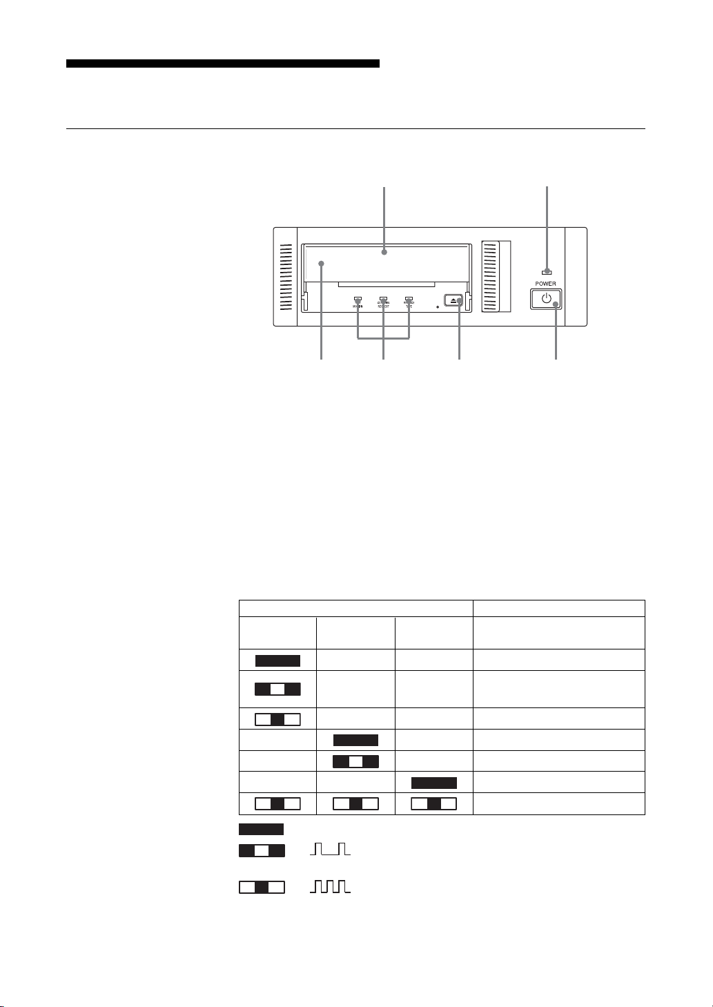
Part Names and Functions
6354
Front Panel
1 AIT Data Cartridge Receptacle
See page 16 to 17 for information on inserting and removing a AIT data
cartridge.
2 POWER Indicator
Lights while the drive is on.
12
Advanced
Intelligent
Tape
3 Dust Cover
This cover protects the AIT data cartridge receptacle.
4 LED Indication for Drive Status
The LED indicators are defined as follows.
LED
TAPE CLEANING REPLACE
MOTION REQUEST TAPE
Independent Independent Tape Loaded
Independent Independent
Independent Independent Tape Access in Progress (others)
Independent Independent Cleaning is requested
Independent Independent Cleaning is Not Completed
Independent Independent Media Error Occurred
on
Slow
1 pulse (0.9 sec on/0.3 sec off)
Fast
1 pulse (0.3 sec on/0.3 sec off)
Tape Access in Progress
(write/read)
H/W Error Occurred
Sense
10 Part 1. Introduction
Page 11

Rear Panel
5 EJECT Button
Push to remove a data cartridge from the drive.
6 POWER Switch
Press to turn the drive on or off.
1
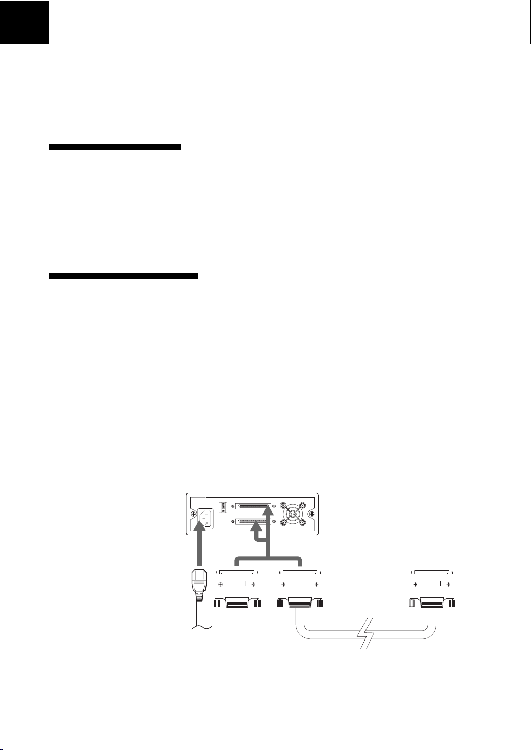
243
1 Rotary Selector Switch
SCSI ID selector.
2 AC IN Connector
Connect the supplied power cable here.
3 SCSI Connector
Connects to the SCSI bus connector of the host computer or another
SCSI peripheral or the terminator.
4 Cooling Fan
Part 1. Introduction 11
Page 12
Part 2. Preparation
After you confirm that you have all of the required accessories for your
installation, connect the drive to the host computer, and select the SCSI ID
with the rotary switch on the rear panel.
Supplied Items
When you first open the box, make sure it contains the following items.
Contact your supplier if anything is missing or broken.
• AIT Drive Unit
• Power Cable
• Operator’s Guide
Interconnections
The SCSI bus allows connection of up to fifteen peripherals to the host
computer. Use a SCSI cable with a half pitch 68 pin connector.
Precautions
• Switch off the host computer and peripherals before connecting the SCSI
cable.
• Make sure the SCSI connectors are pressed tightly together.
• If this unit is the last (or only) device on the Wide SCSI bus, make sure to
connect a terminator to the appropriate unused Wide SCSI connector. Using
an incompatible terminator may damage the unit.
• With an Ultra Wide SCSI bus, the total length of the SCSI cable(s)
connecting the host computer and the last device on the SCSI bus should be
less than 12 meters (39 feet). (If a SCSI single-end host adapter is at the end
of the SCSI bus, use less than 1.5 meters of SCSI cable.)
Terminator
AC power
*1
12 Part 2. Preparation
*1
It should be less than 1.5 meter, if connected to single-ended SCSI host adaptor.
Page 13
SCSI ID Setting
The SCSI ID is set by the rotary switch on the rear panel. Press the + or buttons to move the number up or down, respectively.
As shipped from the factory, the SCSI ID is set to 0. Press the switch buttons,
if necessary, to select the SCSI ID number you require. Because the host
adapter ID is usually set to 7, select some other value for the SCSI ID setting.
Precautions
• The SCSI ID must be different from IDs of the other peripherals on the
SCSI bus.
• When shipped from the factory, SCSI parity is enabled and Term power is
ON. Be sure to connect a terminator to the SCSI bus before use.
• Before changing the SCSI ID setting, be sure to turn off the power with the
POWER switch on the front panel.
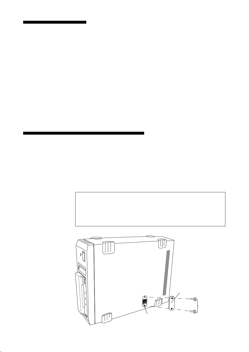
Option Switches (DIP Switch)
Remove the two slotted screws by using a slotted screwdriver. Remove the
access cover to change the DIP switch settings. (Refer to the following
figure for details changing the DIP switch settings.)
After changing the DIP switch settings, replace access cover and tighten the
two slotted screws using a slotted screwdriver.
CAUTION
Before removing the access cover to change DIP switch settings on the
drive, turn off the computer and disconnect the power cord from the unit.
Once the DIP switch settings have been changed, replace the access cover
using the two original slotted screws provided.
Access Cover
Slotted
Screws
DIP Switch
Part 2. Preparation 13
Page 14
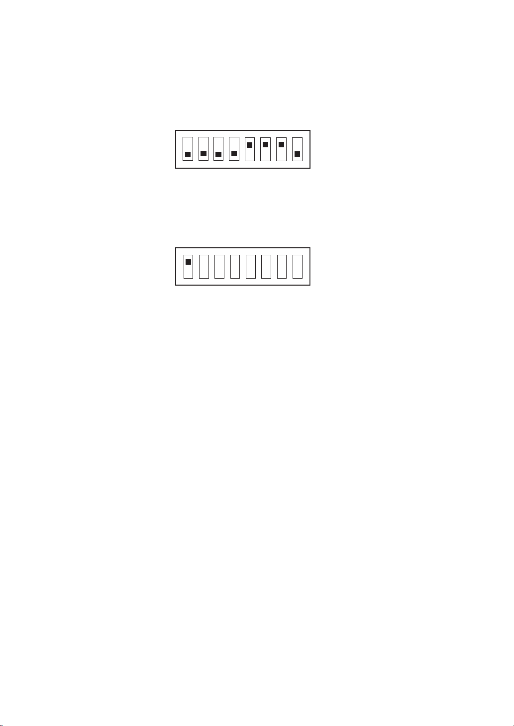
DIP Switch Positions
Default
1 Drive Mode (OFF)
ON
OFF
12345678
2 Drive Mode (OFF)
3 Drive Mode (OFF)
4 Drive Mode (OFF)
5
Terminator Power (ON)
6 Periodic Cleaning Req (ON)
7 DC Control (1) (ON)
8 DC Control (2) (OFF)
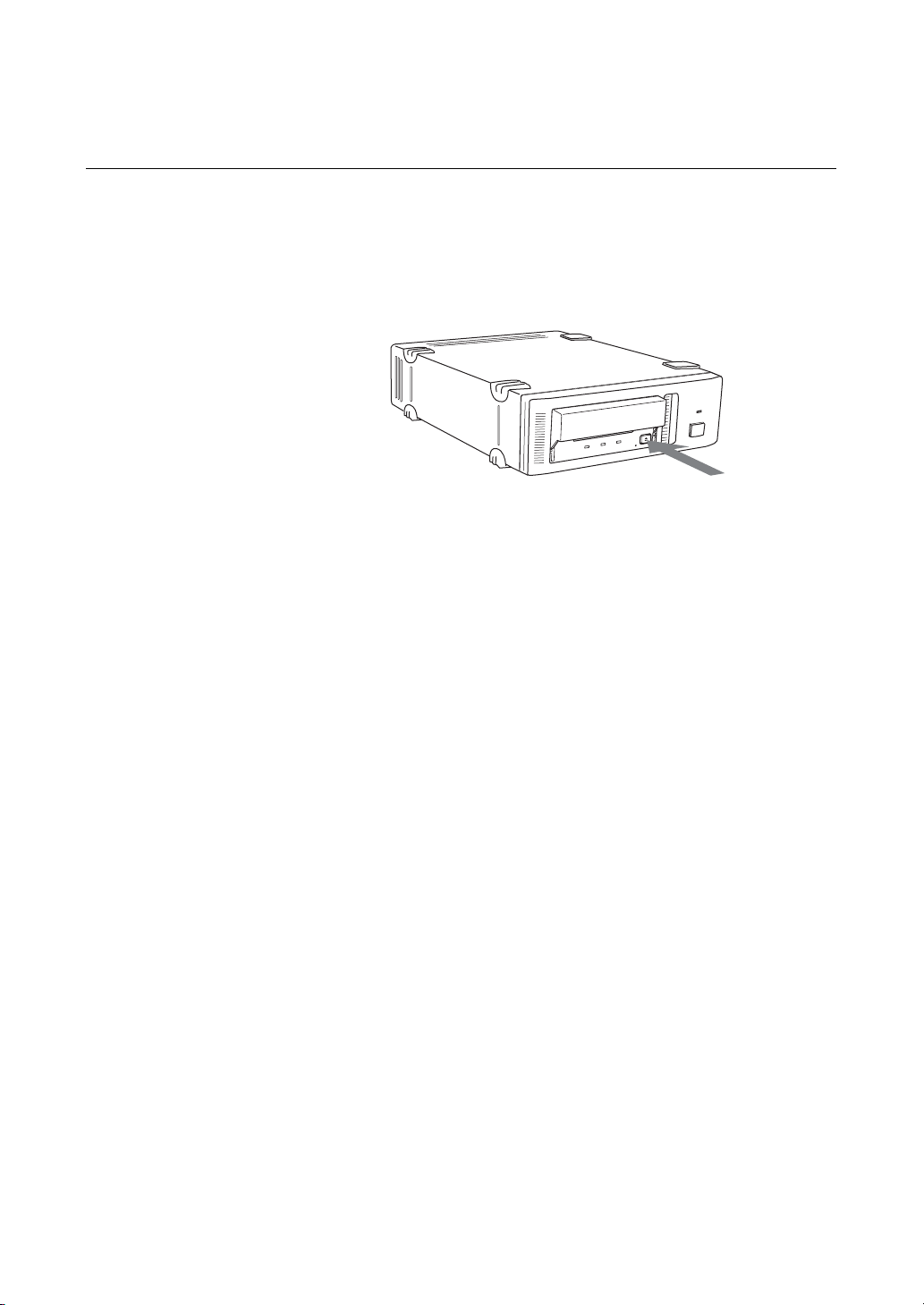
DR (Disaster Recovery*) Mode
To enable DR Mode, set position1 [Drive Mode] Switch to ON.
1 Drive Mode (ON)
ON
OFF
12345678
* In Disaster Recovery Mode, the drive enters the DR Standby Mode 15 seconds
after you insert a write-protected tape into the drive, and all the drive LED blink. If
you restart the drive while the LED are blinking, it starts as a CD-ROM device.
For details about the Disaster Recovery Mode, refer to the instruction manual that
came with the application software you are using.
2 Drive Mode
3 Drive Mode
4 Drive Mode
5
Terminator Power
6 Periodic Cleaning Req
7 DC Control (1)
8 DC Control (2)
14 Part 2. Preparation
Page 15

Cleaning Request Mode
Periodic cleaning requests can be enabled by a DIP switch.
1 Drive Mode
ON
OFF
12345678
2 Drive Mode
3 Drive Mode
4 Drive Mode
5
Terminator Power
6 Periodic Cleaning Req (ON)
7 DC Control (1)
8 DC Control (2)
When switch 6 is ON, cleaning requests are enabled. When enabled, the
“CLEANING REQUEST” LED on the front panel lights after every 100
hours of operation.
When this LED lights, clean the drive with a cleaning cartridge.
Note
To maintain the drive in optimum condition in environments affected by dust
and other contaminants, we recommend keeping cleaning requests enabled.
Terminator Power Control DIP switch
This DIP switch determines whether terminator power is supplied to the
SCSI bus. To enable terminator power, set position 5 [Terminator Power]
switch to ON.
Data Compression Control DIP Switch
Data compression can be selected by DIP switches. Data compression is
enabled while position 7 [DC Control (1)] is ON. Control by host can be
disabled when position 8 [DC Control (2)] is ON.
Part 2. Preparation 15
Page 16

Part 3. Operation
This section describes how to use the AIT drive, and how to handle data
cartridges.
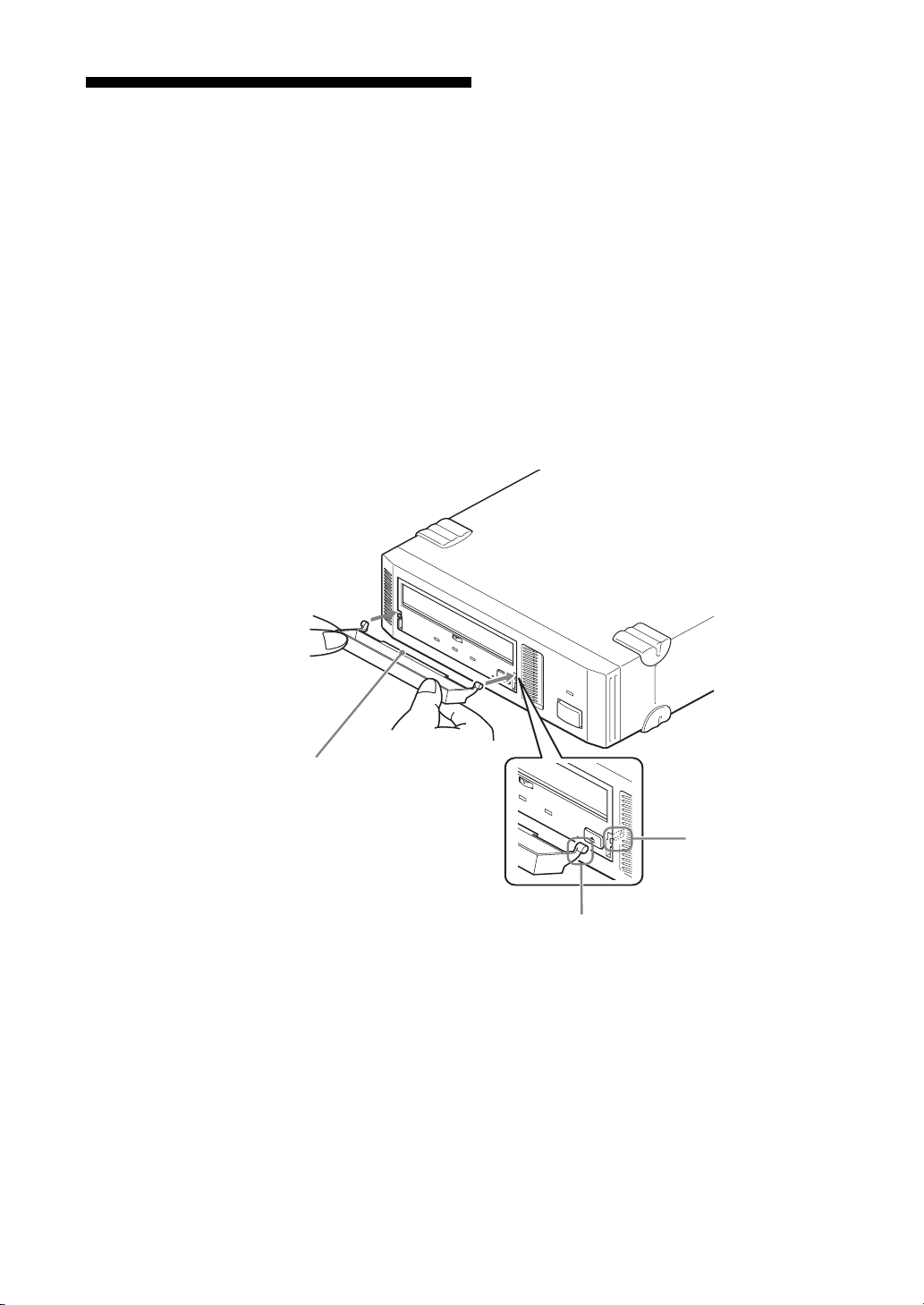
How to use the AIT Drive
1 Press the POWER switch on the front panel.
The POWER indicator should light, and the TAPE MOTION,
CLEANING REQUEST, and REPLACE TAPE indicators should blink
as the self-test is performed.
2 When the three indicators stop blinking, open the dust cover and insert a
data cartridge as shown below. The TAPE MOTION indicator lights.
16 Part 3. Operation
3 Computer software controls the reading and writing of tapes. While
reading or writing, the TAPE MOTION indicator blinks.
4 Close the dust cover.
Page 17
Cartridge Removal
1 Press the EJECT button.
2 Open the dust cover.
The cartridge is ejected automatically.
Caution
Do not push the EJECT button while the TAPE MOTION indicator is
blinking. To do so may destroy data on the tape.
3 Remove the cartridge from the receptacle, and then close the dust cover.
Part 3. Operation 17
Page 18
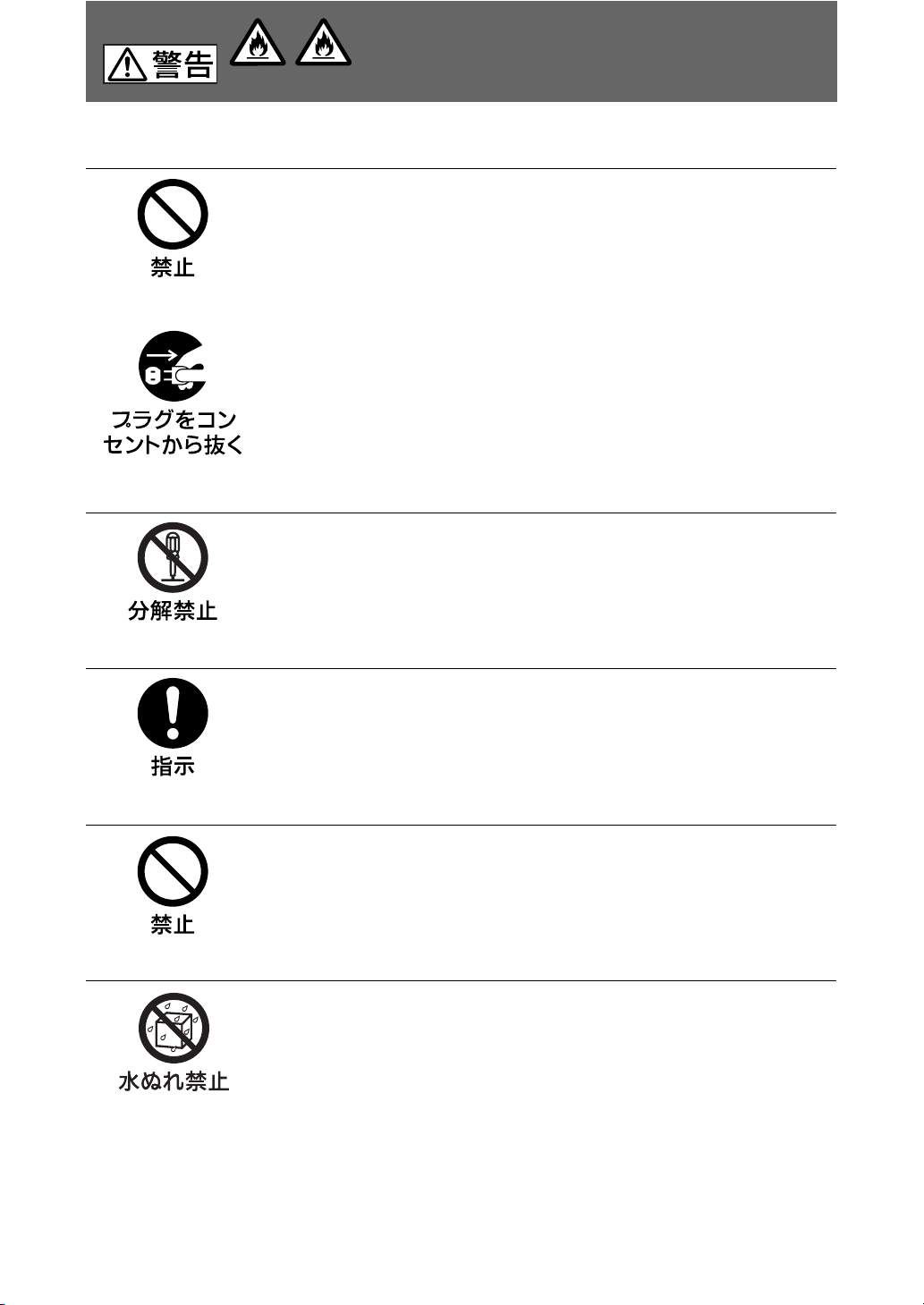
Attaching the Dust Cover
If the dust cover comes loose, attach it as described below.
Note
We recommend that you use the drive with the dust cover.
1 Align the dust cover’s hinge clips (one on each side) with the pins of the
drive bezel.
• The dust cover should be positioned so that the magnets* on the cover’s
back face the drive bezel.
*
This magnet does not affect the tape of the cartridge.
• Holding the dust cover at an angle as shown in the figure below, set the
hinge clips on top of the bezel pins, positioning them so that they
bracket the pins.
18 Part 3. Operation
Magnet
Bezel pin
Hinge clip
Page 19

2 Press down at an angle on each side in turn until you hear the hinge clips
click into place.
Caution
Do not press the dust cover in horizontally from the front. Doing so
could cause the dust cover to break.
3 Close the dust cover.
This completes attachment of the dust cover.
Part 3. Operation 19
Page 20

WORM Function
The SDX-D550V supports the WORM function. This explains the WORM
function.
What is “WORM”?
“WORM” is an acronym for “Write Once Read Many”, a function that allows
data to be written to the same place on a tape only once, but permits that data
to be read from the tape for any number of times. The SDX-D550V supports
WORM cartridges. When a WORM cartridge is used with an application that
supports the WORM function, data that has been written to a tape can not be
accidentally deleted or overwritten.
A WORM drive operates in the same manner as a non-WORM drive when
used with a non-WORM cartridge (henceforth referred to as “regular
cartridge”).
The operation of a WORM drive and a non-WORM drive differs according
to the type of cartridge that is being used.
Non-WORM drive Read/Write Enabled Waiting for Eject
WORM drive Read/Write Enabled Read/
Tape Drive Cartridge
Regular Cartridge WORM Cartridge
(without WORM logo) (with WORM logo)
Append-Write Enabled
WORM Cartridges
WORM cartridges can be distinguished from regular cartridges by their
WORM logo and red shutters.
Red
WORM logo
AIT-2 WORM cartridge: SDX2-50W
20 Part 3. Operation
Page 21

How to Write Data onto a WORM Cartridge
As with a regular cartridge, there is no limit on how many times data can be
read from a WORM cartridge. When writing data to a WORM cartridge, the
data cannot be written to a portion of the tape that data has already been
written.
When writing data onto a WORM cartridge, it is appended after data that has
already been written onto the cartridge. Accordingly, you must move to the
EOD area before writing data onto the cartridge.
SCSI Commands Supported by the WORM Drive
The WORM drives support the same SCSI commands that are supported by
non-WORM drives. However, if an attempt is made to write to a portion of a
tape where data has already been written, the following error information is
returned: “Sense Key = 07, ASC = 27h, ASCQ = 00: Persistent Write
Protect” or “Sense Key = 03, ASC = 27h, ASCQ = 04: Write Position Error.”
Notes
• The manufacturer does not accept liability for data written onto a WORM
cartridge that is lost as a result of using this unit.
• The manufacturer accepts no responsibility for any financial damages, lost
profits, or claims made by third parties arising from the use of this product.
Part 3. Operation 21
Page 22

Part 4. Care and Maintenance
Taking Care of the Drive
Safety Considerations
■ Power
• Be sure to use only 100 V - 240 V AC.
• Avoid plugging into the same outlet as high-current equipment like copiers
or shredders.
■ Power Cable Precautions
• Do not crush the cable or place heavy items on it. If the cable insulation
appears worn or broken, do not use the cable.
• Always unplug the cable by holding the plug. Never pull the cable itself, as
it will break.
• If the drive is not being used for a long time, unplug the cable from the
outlet.
Avoiding Damage
■ Avoid shock and vibration
Intense shock, such as from dropping the drive, will damage it.
■ Environmental considerations
Do not store or use the drive in locations subject to:
•high humidity • excessive dust
• high temperature • intense vibration
• direct sunlight • sudden changes in temperature
■ Proper ventilation
To avoid overheating, install the drive where it will have free air circulation
around the case, and do not cover it during operation. The drive can
malfunction if the internal temperature rises too high.
22 Part 4. Care and Maintenance
Page 23

■ Avoid sudden changes in temperature
If the drive is moved from a cool place to a warm place, or if the room
temperature suddenly rises, moisture may condense inside the case. After a
sudden change in temperature, wait at least one hour before turning the drive
on.
Inserting a cartridge with condensation inside the drive can damage the drive
or the tape. Immediately remove cartridges in the drive if there is a possibility
that there is condensation inside.
Leaving the drive on without inserting cartridges, moreover, will quickly
evaporate any condensation.
■ Abnormal occurrences
If the drive behaves abnormally, or if it begins to smell or smoke,
immediately unplug it from the wall outlet and contact your supplier for
assistance.
■ Cabinet cleaning
Wipe the cabinet with a soft dry cloth. For heavy dirt, wipe with a soft cloth
moistened with a gentle liquid soap, then wipe again with a soft dry cloth. Do
not use alcohol, paint thinner, bug sprays or other volatile solvents, as they
can damage the finish.
Part 4. Care and Maintenance 23
Page 24

Taking Care of Cartridges
Use Precautions
• Avoid heavy vibration and dropping.
• The shutter on the face of the cartridge is opened automatically when it is
inserted into the drive. Do not open the shutter by hand, as touching the tape
may damage it.
• The cartridge was carefully aligned during assembly at the factory. Please
do not try to open it or take it apart.
• The write-protect switch on the face of the cartridge prevents the tape from
being written to or accidentally erased. If you do not need to write to the
tape, move this switch to the write-protect position (in the direction of the
arrow).
• In case of a sudden change in temperature, condensation may interfere with
• Avoid unnecessary insertion and removal of cartridges if you do not need to
• When finished using the drive, remove the cartridge.
Storage Precautions
• Keep cartridges in their cases when not in the drive.
• Avoid storing cartridges in dusty places, in direct sunlight, near heaters or
• Do not place cartridges on the dashboard or in a storage tray in a car.
Using your fingernail, push the switch in the direction of the
arrow to protect the tape from writing or accidental erasure.
Return the switch to its original position to re-enable writing.
reading and writing to a tape.
write or read a tape.
air conditioners, or in humid locations.
24 Part 4. Care and Maintenance
Page 25

Cleaning
How to Clean
To keep the AIT drive in top condition, clean the drive unit as needed using a
cleaning cartridge with the AIT logo (sold separately). When the drive unit
needs cleaning, the CLEANING REQUEST indicator lights.
1 Load the cleaning cartridge (SDX1-CL) into the AIT drive.
Cleaning starts automatically.
2 After about 15 seconds, cleaning will stop and the cartridge will be
ejected automatically.
Notice
Do not rewind the cleaning cartridge and reuse it. When you reach the end of
the cartridge, dispose it and buy a new cleaning cartridge with the AIT logo.
Part 4. Care and Maintenance 25
Page 26

Appendix
Specifications (SDX-D550V)
■ Performance
Storage Capacity 208 GB compressed (with TAIT2-80N,
Bit Error Rate less than 10
Data Transfer Rate 12 MB/s uncompressed
(TAPE)
Burst Data Transfer Rate 12 MB/s maximum, asynchronous
(SCSI) 160 MB/s maximum, synchronous
Initialize Time less than 5 seconds
■ Operating Environment
Operating Temperature: 10 to 35 °C ( ∆T<10 °C / h)
Non-operating Temperature:
TAIT2-80C)
80 GB uncompressed (with TAIT2-80N,
TAIT2-80C)
Humidity:
Maximum wet
bulb temperature: 2 6 °C (78.8 °F)
Humidity:
Maximum wet
bulb temperature: 4 5 °C (113 °F)
*1
-17
(50 to 95 °F (∆T<18 °F / h))
30 to 80% (no-condensing)
–40 to 70 °C (∆T<20 °C / h)
(–40 to 158 °F (∆T<36 °F / h))
10 to 90% (∆RH<30% / h)
■ Power Supply & Miscellaneous
Power Supply 100 V to 240 V AC, 50/60 Hz
Case Dimensions 198 × 64.5 × 246 mm (W × H × D)
Weight 2.4 kg
Accessories Power Cable (1)
Specifications may be subject to change, in the interest of technological
improvement, without notice or obligation.
*1
This is assuming 2.6:1 compression ratio.
The degree of data compression attained while recording data varies according to system
environment and data type.
1.2 A
(excluding protruding parts)
Operator’s Guide (1)
26 Appendix
Page 27

Specifications (SDX-D450V)
■ Performance
Storage Capacity 104 GB compressed (with TAIT1-40N,
Bit Error Rate less than 10
Data Transfer Rate 6 MB/s uncompressed
(TAPE)
Burst Data Transfer Rate 12 MB/s maximum, asynchronous
(SCSI) 40 MB/s maximum, synchronous
Initialize Time less than 5 seconds
■ Operating Environment
Operating Temperature: 10 to 35 °C ( ∆T<10 °C / h)
Non-operating Temperature:
TAIT1-40C)
*1
40 GB uncompressed (with TAIT1-40N,
TAIT1-40C)
-17
(50 to 95 °F (∆T<18 °F / h))
Humidity:
30 to 80% (no-condensing)
Maximum wet
bulb temperature: 2 6 °C (78.8 °F)
–40 to 70 °C (∆T<20 °C / h)
(–40 to 158 °F (∆T<36 °F / h))
Humidity:
10 to 90% (∆RH<30% / h)
Maximum wet
bulb temperature: 4 5 °C (113 °F)
■ Power Supply & Miscellaneous
Power Supply 100 V to 240 V AC, 50/60 Hz
Case Dimensions 198 × 64.5 × 246 mm (W × H × D)
Weight 2.4 kg
Accessories Power Cable (1)
Specifications may be subject to change, in the interest of technological
improvement, without notice or obligation.
*1
This is assuming 2.6:1 compression ratio.
The degree of data compression attained while recording data varies according to system
environment and data type.
1.2 A
(excluding protruding parts)
Operator’s Guide (1)
Appendix 27
Page 28

Specifications (SDX-D250V)
■ Performance
Storage Capacity 52 G B compressed (with TAITE-20N)
Bit Error Rate less than 10
Data Transfer Rate 6 M B/s uncompressed
(TAPE)
Burst Data Transfer Rate 12 MB/s maximum, asynchronous
(SCSI) 40 MB/s maximum, synchronous
Initialize Time less than 5 seconds
■ Operating Environment
Operating Temperature: 10 to 35 °C ( ∆T<10 °C / h)
Non-operating Temperature:
■ Power Supply & Miscellaneous
Power Supply 100 V to 240 V AC, 50/60 Hz
Case Dimensions 198 × 64.5 × 246 mm (W × H × D)
Weight 2.4 kg
Accessories Power Cable (1)
20 GB uncompressed (with TAITE-20N)
-17
(50 to 95 °F (∆T<18 °F / h))
Humidity:
30 to 80% (no-condensing)
Maximum wet
bulb temperature: 2 6 °C (78.8 °F)
–40 to 70 °C (∆T<20 °C / h)
(–40 to 158 °F (∆T<36 °F / h))
Humidity:
10 to 90% (∆RH<30% / h)
Maximum wet
bulb temperature: 4 5 °C (113 °F)
1.2 A
(excluding protruding parts)
Operator’s Guide (1)
*1
28 Appendix
Specifications may be subject to change, in the interest of technological
improvement, without notice or obligation.
*1
This is assuming 2.6:1 compression ratio.
The degree of data compression attained while recording data varies according to system
environment and data type.
Page 29

安全のために
電気製品はまちがった使いかたをすると、火災や感電
などにより死亡や大けがなど人身事故につながること
があり、危険です。
事故を防ぐために次のことを必ずお守りください。
安全のための注意事項を守る
この冊子の注意事項をよくお読みください。
この冊子には、製品全般の注意事項が記されています。
定期的に点検する
長期間、安全にお使いいただくために、定期点検をす
ることをおすすめします。
点検の内容や費用については、お買い上げ店にご相談
ください。
故障したら使わない
すぐに、お買い上げ店またはソニーのサービス窓口に
ご連絡ください。
警告表示の意味
取扱説明書および製品では、
次のような表示をしています。
表示の内容をよく理解してか
ら本文をお読みください。
日
本
語
この表示の注意事項を守らな
いと、火災や感電などにより
死亡や大けがなど人身事故に
つながることがあります。
この表示の注意事項を守らな
いと、感電などによりけがを
したり周辺の物品に損害を与
えたりすることがあります。
万一、異常が起きたら
煙が出たら
•
異常な音、におい
•
がしたら
内部に水、異物が
•
入ったら
製品を落としたり
•
キャビネットを破
損したときは
炎が出たら
,
,
1 電源を切る。
2 電源コードや接続
コードを抜く。
3 お買い上げ店に連絡
する。
● 電源プラグをコンセン
トから抜くか、ブレー
カーを落とす。
●
大声で応援の人を呼ぶ。
● 水をどんどんかける
か、消火器を使って火
を消す。
● 119 番へ通報する。
注意を促す記号
行為を禁止する記号
行為を指示する記号
29
Page 30
下記の注意事項を守らないと、火災や感電に
感電火災
より死亡や大けがにつながることがあります。
電源コードを傷つけない
電源コードを傷つけると、火災や感電の原因となることがあります。
• 設置時に、製品と壁やラック(棚)などの間に、はさみ込んだりしない。
• 電源コードを加工したり、傷つけたりしない。
• 重いものをのせたり、引っ張ったりしない。
• 熱器具に近づけたり、加熱したりしない。
• 電源コードを抜くときは、必ずプラグを持って抜く。
• 電源コードを接続したまま、機器を移動しない。
• 電源コードや電源プラグが傷んだり、コンセントの差し込み口がゆる
いときは使用しない。
万一、電源コードが傷んだら、お買い上げ店に交換をご依頼ください。
内部を開けない
内部には電圧の高い部分があり、キャビネットや裏ぶたを開けたり改造
したりすると、火災や感電の原因となることがあります。内部の調整や
設定、点検、修理はお買い上げ店にご依頼ください。
日本国内で使用する場合
交流 100V でお使いください。
異なる電圧で使うと、火災や感電の原因となることがあります。
内部に水や異物を入れない
水や異物が入ると火災の原因となることがあります。
万一、水や異物が入ったときは、すぐに電源を切り、電源コードや接続
コードを抜いて、お買い上げ店にご相談ください。
水のある場所に設置しない
水が入ったり、ぬれたりすると、火災や感電の原因となることがあり
ます。
30
Page 31

下記の注意事項を守らないと、火災や感電に
感電火災
より死亡や大けがにつながることがあります。
電源プラグの端子、および端子の取付け面にほこりが付着し
ている場合は、乾いた布でよく拭く。
そのまま使用すると火災の原因となります。
電源プラグは、コンセントの奥まで確実に差し込む。
火災、故障の原因となることがあります。
同梱の変換プラグをご使用の際は、アース線をコンセントの
アース端子に接続する。
同梱の3 極 t2 極変換プラグを使用する場合は、変換プラグから出てい
る緑色のアース線を、建物のコンセントに備えられているアース端子に
接続してください。
アース端子のないコンセントには電源コードを接続しないでください。
火災や感電の原因となることがあります。
下記の注意事項を守らないと、
けがをしたり周辺の物品に損害を与えることがあります。
油煙、湯気、湿気、ほこりの多い場所には設置しない
上記のような場所に設置すると、感電の原因となることがあります。
取扱説明書に記されている仕様条件以外の環境での使用は、感電の原因
となることがあります。
通風孔をふさがない
通風孔をふさぐと内部に熱がこもり、火災や故障の原因となることがあ
ります。風通しをよくするために次の項目をお守リください。
壁から 10cm 以上離して設置する。
•
密閉された狭い場所に押し込めない。
•
毛足の長い敷物(じゅうたんや布団など)の上に設置しない。
•
布などで包まない。
•
あお向けや横倒し、逆さまにしない。
•
31
Page 32

下記の注意事項を守らないと、
けがをしたり周辺の物品に損害を与えることがあります。
不安定な場所に設置しない
ぐらついた台の上や傾いたところに設置すると、倒れたり落下したりし
て、けがの原因となることがあります。また、設置・取り付け場所の強
度を十分にお確かめください。
製品の上に乗らない、重い物を乗せない
倒れたり、落ちたり、壊れたりして、けがの原因となることがあります。
機器を移動する場合、あるいはお手入れの際は、電源を切っ
て電源プラグを抜く
電源を接続したままお手入れをすると、感電の原因となることがあります。
接続ケーブルなどもはずしてください。
長時間機器を使用しないときは、安全のため必ず電源プラグをコンセン
トから抜いてください。
指定された電源コード、接続コードを使う
取扱説明書に記されている電源コード、接続コードを使わないと、感電
や故障の原因となることがあります。
ぬれた手で電源プラグをさわらない
ぬれた手で電源プラグを抜き差しすると、感電の原因となることがあり
ます。
接続の際は電源を切る
電源コードや接続コードを接続するときは、電源を切ってください。感
電や故障の原因となることがあります。
32
Page 33

お買い上げいただきありがとうございます。
電気製品は安全のための注意事項を守らないと、火災や人身事故になることがあり
ます。
この取扱説明書には、事故を防ぐための重要な注意事項と製品の取り扱いかたを示しています。
この取扱説明書をよくお読みのうえ、製品を安全にお使いください。
お読みになったあとは、いつでも見られるところに必ず保管してください。
安全認証のための
本製品は機器本体に貼り付けられた銘板に ModelNo. と記載された番号で安全認証機関に登録
されています。認証の照合など、必要な場合はこの ModelNo. をご参照ください。
RoHS
この装置は、情報処理装置等電波障害自主規制協議会(VCCI)の基準に基づくクラス B 情報
技術装置です。この装置は、家庭環境で使用することを目的としていますが、この装置がラ
ジオやテレビジョン受信機に近接して使用されると、受信障害を引き起こすことがあります。
取扱説明書に従って正しい取り扱いをして下さい。
指令(欧州環境規制)に対応済
Model No.
33
Page 34

目次
第1章 概要
第2章 準備
第3章 使いかた
説明書の使いかた .........................................................................................
ドライブユニットについて ....................................................................
AIT
特長................................................................................................................ 36
使用できるカートリッジ ...................................................................................37
システム構成 .................................................................................................. 37
各部の名称と働き .........................................................................................
前面................................................................................................................ 38
後面................................................................................................................ 40
付属品を確認する .........................................................................................
接続のしかた.................................................................................................
SCSI ID
DIP
AIT
防塵カバーの取り付け ..................................................................................
WORM
の設定 ............................................................................................
スイッチの設定 ......................................................................................
DIPスイッチの設定 ........................................................................................44
TerminatorPowerControlDIPスイッチ .....................................................46
DIPスイッチでのデータ圧縮コントロール ..................................................... 46
ドライブユニットを使う .......................................................................
カートリッジを 取り出 すには ............................................................................ 48
機能について ...................................................................................
35
36
38
41
42
43
44
47
49
51
第4章 取り扱い
について
付録
34 目次
本機の取り扱い .............................................................................................
安全にお使いいただくために .......................................................................53
万一の故障を防ぐ ために .............................................................................. 53
その他ご 注意いただきたいこと .................................................................... 54
カートリッジの取り扱い...............................................................................
取り扱い上のご注意 ...................................................................................... 55
保管上のご注意 ............................................................................................55
クリーニングについて ..................................................................................
クリーニングのし かた .................................................................................... 56
主な仕様 ........................................................................................................
性能................................................................................................................ 57
環境条件 ........................................................................................................ 59
電源・そ の他 .................................................................................................59
53
55
56
57
Page 35

説明書の使いかた
この取扱説明書は、AITドライブユニットの 使 いかた、取り扱 い か たにつ い て説明して
います。お 使いになる前に必ずお読みください。
お読みになったあとは、後日お役に立つこともありますので、保存しておいてくだ
さい。
この説明書は、次の 4つの章と付録で構成されています。
目的に合わせてお読みください 。
章 概要
□第
1
本機の特長やシステム構成、各部の名称と働きなどについて説明しています。
□第2章 準備
本機とホストコンピューター や他のSCSI周辺機器との接続のしかたと本機の機能や
SCSIIDの設定のしかたについて説明しています。設置の際にお読みください。
章 使いかた
□第
3
本機の電源の入れかた、カートリッジ の 入 れかた、取り出しか たに つ い て説明してい
ます。実際にお 使 いになるときにお読みください 。
章 取り扱いについて
□第
4
本機やカートリッジ の 取り扱 い上の注意について説明しています。また、クリー ニ ン グ
についても説明していますので、お使いになる前に必ずお読みください。
□付録
本機の主な仕様について、説明しています。
35説明書の使いかた
Page 36

第1章 概要
ドライブユニットについて
AIT
SDX-D550V/D450V/SDX-D250Vは以下のフォーマットに 対 応 し た 外付けドライブユ
ニットで す 。
SDX-D550V
SDX-D450V
SDX-D250V
特長
本機には次の特長があります。
□ SDX-D550V/D450V/SDX-D250Vは以下に大容量記録できます。
SDX-D550V
SDX-D450V
SDX-D250V
対応フォーマット
AIT-ETurbo/AIT-1/AIT-1Turbo/AIT-2/AIT-2Turbo
AIT-ETurbo/AIT-1/AIT-1Turbo
AIT-ETurbo
記録できるデータ容量
80Gバイト
(データ圧縮なし)
* TAIT2-80N、TAIT2-80C使用時
(TAIT1-40N、TAIT1-40C、TAITE-20N 使用時は
SDX-D450Vと同様)
40Gバイト
(データ圧縮なし)
* TAIT1-40N、TAIT1-40C使用時
(TAITE-20N使用時はSDX-D250Vと同様)
20Gバイト
(データ圧縮なし)
36 第
章 概要
1
また、リードアフターライト機 能 と第 3 レベルのエラー訂正コードの採用により、高
いデータ信頼性を実現しています。
□本機は、データ圧縮機能を持っているので、さらに 多くのデータを記 録 できます。
□本機は、カートリッジ に 記 録され ているデ ータが 圧 縮され て いるのか、されて いな
いのかを自動判別します。他の機器で記録されたデータも、そのまま読み出すこ
とができます。
□ SCSIインターフェース
SDX-D550V:Ultra160SCSILVD/ SE 準拠
SDX-D450V/ SDX-D250V:UltraWideSCSILVD / SE 準拠
Page 37

使用できるカートリッジ
SDX-D550Vには、AIT-ETurbo、AIT-1Turbo、AIT-2Turbo、AIT-1、AIT-2 のロゴの
ついたデータカートリッジ を 使 用し てください。
SDX-D450Vには、AIT-ETurbo、AIT-1Turbo、AIT-1のロゴのついたデータカートリッ
ジを使用してください。
SDX-D250Vには、AIT-ETurboロゴのついたデータカートリッジを 使 用し てください。
システム構成
AIT-E Turbo AIT-1 Turbo
マーク マーク マーク
ご注意
AIT-2 Turbo
AIT-1
マーク
AIT-2
• 本機には、専用のAIT データカートリッジ を 使 用し てください。
• 市販の8mmビデオテープは、外観は似ていますが、仕様がまったく違うので使用
できませ ん。8mmビデオテープなどAITカートリッジ 以 外 のカートリッジを セットしな
いでください 。故 障 の原因になります。
本機は、通常はインターフェースとして UltraWideLVD/ SESCSIを採用している
ホストコンピ ュ ーター に 接 続 し ま す 。
ホストコンピューター
Wide(16
ビット)
ピンケーブル
68
ピンケーブル
68
マーク
本機
Wide SCSI
周辺機器 ターミネーター
第
章 概要 37
1
Page 38

各部の名称と働き
1
2
前面
Advanced
Intelligent
Tape
4
3
5 6 7
8
1 データカートリッジ挿入口
AITデータカートリッジ を 入 れ ま す 。カートリッジ の 入 れかた、出し か た については
47、48 ページをご覧ください。
2
POWER
電源が投入(オン)され ている間、点灯します 。
インジケーター
3 防塵カバー
データカートリッジ 挿入口を保護するカバーです。
4
TAPE MOTION
AITデータカートリッジ が収納されている間、点灯します。また、以下のようなとき
には点滅します。
カートリッジが挿入されているとき
カートリッジにデータを
しているとき
カートリッジに
作をしているとき
5
CLEANING REQUEST
クリー ニ ン グ に 関 す る ス テ ータス状 態を表 示します。
クリーニングが必要なとき 点灯します。
クリーニング動作が進行中のとき
インジケーター
Read/Write
Read/Write
点灯します。
等間隔に点滅します。
以外の動
インジケーター
長い点灯と短い消灯を繰り返します。
長い点灯と短い消灯を繰り返します。
38 第
章 概要
1
Page 39

6
REPLACE TAPE
挿入されているAITデータカートリッジ の 状 態 を 表 示し ます 。
カートリッジが劣化してきたとき 等間隔に点滅します。
カートリッジを交換すべき時期が来た
とき
*
*テープに起因するエラーが一 定レベ ル 以 上に達したとき
• さらに4、5、6のインジケーターが 同 時 に 点 滅する場合は、ハードウェア的 な 問 題
が起きていることを示します。
カートリッジを 入れ替えたり、電源を入れなおしても同じ状態が続くようなら、本機のお
買い上げ店に点検・修理をご相談ください。
インジケーター
点灯します。
7
EJECT
AITデータカートリッジ を 本 機 から 取り 出 すときに押します。
8
POWER
電源を入れたり切ったり(オン/オフ)するときに押します。
ボタン
スイッチ
第
章 概要 39
1
Page 40

後面
1
243
1 ロータリースイッチ
SCSIIDを設定します。
2
AC IN
付属の電源コードを接 続します 。
3
Wide SCSI
WideSCSIケーブルを使って、ホストコンピューター の WideSCSIバスコネクター,
または他の SCSI 周辺機器やターミネ ーターに 接 続します 。
コネクター
コネクター
4 ファン
40 第
章 概要
1
Page 41

第2章 準備
付属品を確認する
付属品を確認してから、本機をホストコンピューター や SCSI周辺機器に接続します。
接続が終わったら、ロータリー スイッチ で SCSIIDを設定します。
梱包を開いたら、本体および下記の付属品がそろっているか確認してください 。不足
しているものがあったり、何らか の 損傷がある場合には、お買い上げ店にご相談くだ
さい。
□ AITドライブユニット本 体
□電源コード
□ 取扱説明書
第
章 準備 41
2
Page 42

接続のしかた
WideSCSIバスを通して、1台のホストコンピューターに15台まで の WideSCSI周辺
機器を接続できます。
接続には、市販のUltraWideSCSIケーブルをお使いください 。
尚、本機側は 68ピンハーフピッチ のコネクターを使 用しています 。
ご注意
• WideSCSIケーブルを接続するときは、コンピューターおよびすべての接続機器の
電源を切ってから行ってください。
• WideSCSIケーブルのコネクター部は最後までしっかり挿入してください。
• 本機をWideSCSIバスの終端に接続する場合は、使用しない側のWideSCSIコネ
クターに 必ず適切なターミネ ーターを 取り付け てください 。誤ったターミネーターを 使
用すると機器が損傷する恐れがあります。
• UltraWideSCSI では、ホストコンピューターと SCSI バス上の最後の機器とをつな
ぐSCSIケーブルの全長が12m未満になるようにしてください 。(SCSI終端となるシ
ングルエンドのSCSIホストア ダ プターに 接続する場合は、1.5m未満のSCSIケーブ
ルを使用してください。)
42 第
章 準備
2
AC
電源
ターミネーター
Page 43

SCSI ID
の設定
後面のロータリー スイッチ の 上下の(+−)ボタンを押すと本機のSCSIIDが表示
された値に 設定できます。
工場出荷時は、「0」に設定されています。設定したいSCSIIDが表示されるまで繰
り返しボタンを押し てください。通常7はホストア ダ プ ター の I D に 設定されていますの
で、それ以外の値に設定します。
ご注意
• SCSIIDは、他の周辺機器と重複しないように設定してください。
• SCSIparityは enable になっています。また、TermpowerはONになっています。
また、ターミネーターをかならず SCSI バスに接続してお使いください。
• SCSIID の設定は、フロントパ ネルの POWERスイッチにより電源を切った状態で
行ってください。
第
章 準備 43
2
Page 44

スイッチの設定
DIP
ドライバーで ネジ(2 個)をゆるめてカバーを取りはずし、下図を 参照して、DIPスイッ
チの設定を変更してください。
設定を変更した後は、カバーをもとのように 取り 付 け てください。
ご注意
• カバーを取りはずす前に、本機の電源を切って、本体から電源コードを 抜 い て お い
てください 。
• DIPスイッチ の 設定変更後、カバーは、もともと使 用され て い た 正規のネジで固定し
てください 。
カバー
スイッチの設定
DIP
44 第
章 準備
2
工場出荷時
ON
OFF
12345678
DIP
スイッチ
ネジ
OFF
)
)
)
)
)
)
1 Drive Mode(OFF
2 Drive Mode(OFF
3 Drive Mode(OFF
4 Drive Mode(OFF
5 Terminator Power(ON
6 Periodic Cleaning Req (ON)
データ圧縮(1)(ON)
7
データ圧縮(2)(
8
Page 45

DR (Disaster Recovery)* Mode
DRModeを有効にするには、DIP スイッチ 1[DriveMode]をONにします。
)
ON
OFF
1 Drive Mode(ON
2Drive Mode
3Drive Mode
4Drive Mode
12345678
5 Terminator Power
6 Periodic Cleaning Req
データ圧縮(1)
7
データ圧縮(2)
8
* DisasterRecoveryModeの場合、ライトプ ロ テクトテ ー プ を 挿 入後15秒間はDRスタンバイモー
ドとなり、すべてのLEDが点滅します。点滅中にドライブの電源を入れ直すと、CD-ROMデバ
イスとし て 起 動 し ま す 。
DisasterRecoveryMode の詳細については、お使いのアプリケーションソフトの取 扱説明書
などを参 照してください 。
Cleaning Request Mode
ディップ スイッチ でクリー ニン グリクエストを設定できます。
ON
OFF
12345678
1Drive Mode
2Drive Mode
3Drive Mode
4Drive Mode
5 Terminator Power
6 Periodic Cleaning Req (ON)
データ圧縮(1)
7
データ圧縮(2)
8
6番目のディップ スイッチを O N に すると、クリーニ ン グ リクエストが有効になります。こ
の場合、動作 100 時間ごとに、前面パネルのCLEANINGREQUESTLEDが点
灯します。
CLEANINGREQUESTLEDが点灯しているときは、クリー ニ ン グ テ ー プ で クリー
ニングを 実 施してください。
メモ
ほこり等の気になる環境で、ドライブを最適な状態に 保 つためには、クリーニ ン グ リク
エストを有効にしてご使用になることをおすすめします。
第
章 準備 45
2
Page 46

Terminator Power Control DIP
この DIPスイッチ で、ターミネ ーター に 電 源 を 供給するかどうかを設定できます。
ターミネ ーターへの電源供給を有効にするには、DIPスイッチ 5[TerminatorPower]
をONにします。
スイッチでのデータ圧縮コントロール
DIP
DIPスイッチによるデータ圧縮の設定は、次のとおりです。
• DIPスイッチ 7[デ ータ圧 縮(1)]がONのとき、初期設定としてデータ圧縮が可能
になります。
• DIPスイッチ 8[データ圧縮(2)]が OFFのとき、ホストコンピ ュ ーター からの デ ータ
圧縮コントロールが可 能になります。
スイッチ
46 第
章 準備
2
Page 47

第3章 使いかた
ここで は 、AITドライブユニットの 立 ち上げかた、カートリッジ の 取り扱 いかたなどにつ
いて説明します。
AIT
ドライブユニットを使う
1 フロントパ ネルの POWERスイッチを 入 れます。
電源が入り、POWERインジケーターが 点 灯します。セルフチ ェックが 始まり、
TAPEMOTIONインジケーター、CLEANINGREQUESTインジケーターおよ び
REPLACETAPEインジケーター が 点 滅します。
2 3つのインジケーター の 点 滅 が 終 わったら、防塵カバーを開き、AITデータカート
リッジ を 下図の向きに挿入します。
TAPEMOTIONインジケーター が 点 灯します。
3 コンピューター上 でソフトウェアを使って、テープ上のデータを読み取ったり、書
き込んだりします。
読み取り、書き込み中は、TAPEMOTIONインジケーター が 点 滅します。
4 防塵カバーを閉めます。
第
章 使いかた 47
3
Page 48

カートリッジを取り出すには
1 EJECTボタンを押します。
2 防塵カバーが開き、AITカートリッジ は自動的に排出されます。
ご注意
TAPEMOTIONインジ ケーターが点滅中はEJECTボタンを押さないでください。
TAPEMOTIONインジケーターが 点 滅し て いるときにカートリッジ を 取り出 す と、
テープ上に記録されているデータが破壊される恐れ があります 。
3 データカートリッジ 挿 入 口 から AITカートリッジ を 取り出し、防塵カバーを閉めます。
48 第
章 使いかた
3
Page 49

防塵カバーの取り付け
防塵カバーが外れた場合は、以下の手順で取り付けてください。
メモ
防塵カバー付きでのご使用をお勧めします。
1 図のように、防塵カバーを斜めに傾け、防塵カバーのヒンジ(左右 2か所)をドラ
イブのベゼルの溝に合わせます。
• 防塵カバー裏面のマグネット* がドライブのベゼルと向き合うように 合 わせてくだ
さい。
*このマグネットは 、テ ー プ に 影 響を及ぼすものではありませ ん 。
マグネット
ヒンジ
ベゼルの溝
第
章 使いかた 49
3
Page 50

2 防塵カバーの両端を、やや斜め上から、片方ずつカチッと音がするまで押して取
り付けます。
ご注意
水平に押し込まないでください 。防 塵カバーが 壊 れる恐 れがあります。
50 第
章 使いかた
3
3 防塵カバーを閉じる。
これで取り付け完了です。
Page 51

WORM
機能について
ここで は 、AITドライブのWORM機能について説明します。SDX-D550VはWORM機
能に対応しています。
WORM
とは
WORMとはWriteOnceReadManyの略で、テープ上の同一箇所への書き込みは
一度しかできませんが、テープからの読み出しは何度でもできる機能です。
SDX-D550VはWORMカートリッジ を サ ポ ートしています。WORM機能をサポートして
いるアプリケーションとともに WORMカートリッジを 使 用 す ると、いったん書き込まれた
データが、誤って消去されたり上書きされて消えてしまうことが ありま せ ん 。
なお、通常のカートリッジ(WORM非対応カートリッジ )を使用した場合、使用方法は
従来どおりですが、WORM機能を使用することはできません。
使用するカートリッジ に より、WORM非対応ドライブとWORM対応ドライブの動作は以
下のように異なります。
ドライブユニット カートリッジ
AIT
通常のカートリッジ
(
WORM
WORM非対応ドライブ 書き込み / 読み出し可能 イジェクト待ち
WORM対応ドライブ 書き込み / 読み出し可能 読み出し可能、
WORM
カートリッジ
マークなし)
WORM
(
書き込みは追 記のみ可能
WORM
カートリッジ
マークなし)
WORMカートリッジ に は 、WORMマークがあり、赤色シャッターが付いていますので、
通常のカートリッジと 区 別 す ることが できます。
赤色
マーク
WORM
AIT-2WORMカートリッジ : SDX2-50W
第
章 使いかた 51
3
Page 52

WORM
データの読み出しについては、通常のカートリッジと 同 様 に 制 限 はありません。データ
の書き込みについては、すでに書き込まれている部分には書き込むことが で きませ
ん。
データを書き込む場合は、すでに書き込まれているデータの後に追記してください。し
たがって、必ず EOD エリアに移動してから書き込みを行う必要があります。
SCSI
サポートしているSCSIコマンドは、WORM非対応ドライブと同じで す。ただし、す で
に書き込まれている部分に書き込もうとすると、「 Sense Ke = 07, ASC = 27h,
ASCQ = 00 : Persistent Write Protect」または「Sense Key = 03, ASC = 27h,
ASCQ = 04:WritePositionError」というエラー情報を返します。
ご注意
• 本機を使用して、なんらか の不具合により書き込んだデータが消去された場合の
• 本機使用によって生じた金銭上の損害、逸失利益、および第三者からのいかなる
カートリッジを使った場合のデータ書き込み方法
コマンド
データ内容の補償については、ご容赦ください。
請求等につきましても、当社は一切その責任を負いかねます。
52 第
章 使いかた
3
Page 53

第4章 取り扱いについて
本機の取り扱い
安全にお使いいただくために
■電源
□ AC100Vでお使いください。
□複写機やシュレッダーのような 消費電力の大きい機器と同じコンセントから、電源
をとらな いでください。
■ 電源コードの取り扱い
□コードの上に重いものをのせたり落としたりして、傷をつけないようにご注意くだ
さい。傷が つい たまま使うと危険です。
□電源コードをコンセントから抜くときは 、必ずプラグを持って抜いてください。コー
ドを引 っ 張 ると、コードが傷むことがあります。
□ 長時間お使いにならないときは、電源コードをコンセントから抜いておいてくだ
さい。
万一の故障を防ぐために
■ 衝撃・振動を与えないでください
落としたりして強い衝撃を与えると、故障することがあります。
■ 設置場所
次のような場所で、使用したり保管しないでください 。
□ 湿気の多いところ □ ほこりの多いところ
□ 温度の高いところ □ 激しい振動のあるところ
□ 直射日光の当たるところ □ 温度変化の激しいところ
■通風
前面の空気穴をふさがないようにしてください 。空気穴をふさぐと本体内部の温度が
上昇し、正常に動作しなくなることが あります 。
第
章 取り扱いについて 53
4
Page 54

■ 急激な温度変化は避けてください
寒いところから暖かいところに移したり、室温を急激に 上げたときは、内部に結露が
起こる場合がありま す 。急激な温度変化があった直後は使わずに、1時間以上待って
からお 使 いください 。
結露が発生したままカートリッジ を 使い続けると、ドライブやテープに支障をきたすこと
があります。結露が起きている可能性があるときは、すぐにカートリッジ を 取 り出し てく
ださい。
なお、カートリッジ を 入れずに、本機の電源を入れたままにしておくと、結 露 が早く解
消します。
■ 異常が起きたら
万一、異常や不具合が生じた場合は、電源コードをコンセントから抜き、お買い上げ
店にご相談ください。
その他ご注意いただきたいこと
■ 雑音電波について
本機は高周波の信号を扱うため、ラジオ や テレビ 、オーディオチューナーなどに雑音
が入ること が ありま す 。この場合は、距離を少し離してご使用ください 。
この装置は、情報処理装置等電波障害自主規制協議会(VCCI)の基準に基づ
くクラ スB 情報技術装置です。この装置は、家庭環境で使用することを目的として
いますが、この装置がラジオやテレビジョン受信機に近接して使用されると、受信
障害を引き起こすことがあります。
取扱説明書に従って正しい取り扱いをしてください。
■ キャビネットが汚れたら
キャビネットの 汚 れ は 、乾いた柔らかい布で拭きとってください 。汚れがひどいときは、
うす い 中 性洗剤溶液を少し含ませた布でふきとり、乾いた布でからぶきしてください。
アルコール・シンナー・殺虫剤など、揮発性の溶剤は、使用しないでください 。表面
の仕上げをいためたり、表示が消えたりすることがあります。
54 第
章 取り扱いについて
4
Page 55

カートリッジの取り扱い
取り扱い上のご注意
□カートリッジ に 激し い振動を与えたり、落としたりしないでください。
□カートリッジ は 、本機に挿入されると自動的にリッドが開く自動装填式です。カート
リッジ のリッドを 手で開けて、中のテープに触れないでください。
□カートリッジ は 工場出荷時に精密に調整されていますので、分解しないでくだ
さい。
□カートリッジ の ツメは 、不用なデータを誤って書き込まないためのものです。書き
込みの必要がないカートリッジ は 、書き 込 み が できな い状態にしておいてくだ
さい。
AIT-1 AIT-E Turbo、AIT-1 Turbo
AIT-2 Turbo、AIT-2
リッド
リッド
、
ツメを左側に押すと書き込みや消去を行うことがで
きる。<
ツメを右側に押すと書き込みや不慮の消去を防ぐこ
とができる。,
□ 温度差の激しい所や湿気の多い所では、結露により書き込み、読み取りができ
なくなることがあります。
□書き込み、読み取りの 必 要 がないときは、不必要に本体にカートリッジを 出し 入 れ
しないでください。
□ ご使用後は必ず本体からカートリッジ を 取り出し て お い てください。
保管上のご注意
□カートリッジ は ケースに入れて保 管してください。
□ほこりやちりの多 い 所、直射日光の当たる所、暖房機の近く、湿気の多い所には
保管しないでください。
□ 自動車のダッシュボードやトレーには絶対に置かないでください。
ツメを下げると書き込みや消去を行うことがで
きる。m
ツメを上げると書き込みや不慮の消去を防ぐことが
できる。M
第
章 取り扱いについて 55
4
Page 56

クリーニングについて
AITドライブユニットを最適な状態に保つために、必要に応じて別売りの AITロゴのつ
いたクリー ニ ン グ カートリッジを 使 い 、クリーニ ン グ す ることを お す す めし ます 。クリー ニ
ングが必要になると、CLEANINGREQUESTインジケーターが 点 滅します。(39ペー
ジ)
クリーニングのしかた
1
本機のデータカートリッジ 挿入口に、クリー ニ ン グ カ ートリッジを 挿 入し ま す 。
自動的にクリー ニ ン グ が 始 まりま す 。
2 約15秒後にクリー ニ ン グ が終了し、クリー ニン グ カ ートリッジ が自動的に出てきま
す。
ご注意
クリー ニ ン グ カ ートリッジ の テ ープを巻き戻して再利用しないでください。クリー ニ
ングカートリッジ を 使 い 切 っ た 場合は、処分して新しくAITロゴのついたデータ
カートリッジを お 買 い 求 めください。
56 第
章 取り扱いについて
4
Page 57

付録
主な仕様
性能
SDX-D550V
AIT-2 Turbo
モード
記憶容量 80G バイト(非圧縮、TAIT2-80N、TAIT2-80C使用時)
208Gバイト(圧縮、TAIT2-80N、TAIT2-80C 使用時)
データ転送速度(TAPE)
12Mバイト/ 秒(非圧縮時)
バーストデ ータ転送速度(SCSI)
160Mバイト/ 秒(最大)
ビットエラーレート
-17
以下
10
AIT-1 Turbo
モード
記憶容量 40G バイト(非圧縮、TAIT1-40N、TAIT1-40C使用時)
104Gバイト(圧縮、TAIT1-40N、TAIT1-40C 使用時)
データ転送速度(TAPE)
6Mバイト/ 秒(非圧縮時)
バーストデ ータ転送速度(SCSI)
40Mバイト/ 秒(最大)
ビットエラーレート
-17
以下
10
*1
*1
AIT-E Turbo
モード
記憶容量 20G バイト(非圧縮、TAITE-20N 使用時)
52Gバイト(圧縮、TAITE-20N 使用時)
*1
データ転送速度(TAPE)
6Mバイト/ 秒(非圧縮時)
バーストデ ータ転送速度(SCSI)
40Mバイト/ 秒(最大)
ビットエラーレート
-17
以下
10
*1
2.6:1ハードウェア圧縮時での数値です。
記録データの圧縮比は、システム環境とデータの種類によって異なります。
付録 57
Page 58

SDX-D450V
AIT-1 Turbo
モード
記憶容量 40G バイト(非圧縮、TAIT1-40N、TAIT1-40C使用時)
104Gバイト(圧縮、TAIT1-40N、TAIT1-40C 使用時)
データ転送速度(TAPE)
6Mバイト/ 秒(非圧縮時)
バーストデ ータ転送速度(SCSI)
40Mバイト/ 秒(最大)
ビットエラーレート
-17
以下
10
AIT-E Turbo
モード
記憶容量 20G バイト(非圧縮、TAITE-20N 使用時)
52Gバイト(圧縮、TAITE-20N 使用時)
*1
データ転送速度(TAPE)
6Mバイト/ 秒(非圧縮時)
バーストデ ータ転送速度(SCSI)
40Mバイト/ 秒(最大)
ビットエラーレート
-17
以下
10
*1
*1
2.6:1ハードウェア圧縮時での数値です。
記録データの圧縮比は、システム環境とデータの種類によって異なります。
58 付録
Page 59

SDX-D250V
記憶容量 20G バイト(非圧縮、TAITE-20N 使用時)
52Gバイト(圧縮、TAITE-20N 使用時)
*1
データ転送速度(TAPE)
6Mバイト/ 秒(非圧縮時)
バーストデ ータ転送速度(SCSI)
40Mバイト/ 秒(最大)
ビットエラーレート
-17
以下
10
*1
2.6:1ハードウェア圧縮時での数値です。
記録データの圧縮比は、システム環境とデータの種類によって異なります。
環境条件
使用時
温度: 10 ℃〜35 ℃(∆T<10 °C/h)
湿度: 30%〜 80%(結露のないこと)(最大湿球温度:26℃)
非動作時
温度: −40 ℃〜 70 ℃(∆T<20 °C/h)
湿度: 10%〜 90%(∆RH<30%/h)(最大湿球温度:45 ℃)
電源・その他
電源定格 AC100V−240V50 /60 Hz 最大1.2A
最大外形寸法 198mm× 64.5mm × 246mm(幅/高さ/奥行き)(突起部を含まず)
質量 2.4kg
付属品 電源コード(1)
取扱説明書(1)
仕様および外観は、改良のため予告なく変更することがありますが、ご了承ください。
付録 59
Page 60

Règles de sécurité
Informations spécifiques de l’utilisateur
Les numéros du modèle et de série sont situés sous l’appareil. Inscrivez les
numéros de série dans l’espace prévu ci dessous.
Reférez vous y chaque fois que vous appelez votre revendeur Sony à propos
de ce matériel.
No de modèle No de série
________________________ __________________________________
Informations
AVERTISSEMENT
Afin de réduire les risques d’incendie ou de choc
électrique, n’exposez pas cet appareil à la pluie ni à
l’humidité.
Pour éviter une électrocution, ne tentez pas d’ouvrir le
module.
Confier l’entretien à un spécialiste uniquement.
Numéro de modèle pour conformité à la régulation
Votre lecteur SDX-D550V a reçu le numéro de modèle ATDEA3 pour
homologation en conformité avec la réglementation.
Votre lecteur SDX-D450V ou SDX-D250V a reçu le numéro de modèle
ATDEA2 pour homologation en conformité avec la réglementation.
Le numéro est indiqué sur l’étiquette de référence du modèle sur votre
lecteur, avec la tension et le courant nominal.
60 Règles de sécurité
Page 61

Attention
La fiche secteur de cet appareil doit être utilisée pour couper l’alimentation.
La prise de courant doit être située près de l’appareil pour être facilement
accessible.
AVERTISSEMENT
Utilisez le cordon d’alimentation approuvé par l’organisme d’essais
compétent dans chaque pays où cet appareil doit être utilisé.
Français
Règles de sécurité 61
Page 62

CONSIGNES DE SECURITE
IMPORTANTES
Avant d’utiliser l’appareil, lisez attentivement ces
consignes de sécurité destinées à vous protéger.
Conservez ce manuel pour pouvoir vous y référer
ultérieurement.
Respectez strictement tous les avertissements, mises
en garde et instructions figurant sur l’appareil ou
celles indiquées dans le mode d’emploi.
UTILISATION
Sources d’alimentation – Cet appareil ne peut
fonctionner qu’avec le type d’alimentation spécifié
sur l’étiquette. Si vous n’êtes pas sûr du type
d’alimentation électrique, adressez-vous à votre
revendeur ou à la compagnie d’électricité régionale.
Pour l’appareil équipé d’une fiche secteur à trois
fils dont un réservé à la mise à la terre:
Si vous n’arrivez pas à insérer la fiche dans la prise,
adressez-vous à un électricien pour faire installer la
prise qui convient. La sécurité garantie par la fiche
de mise à la terre ne doit pas être neutralisée.
Cordon d’alimentation secteur:
Le cordon d’alimentation secteur doit être pourvu
des marquages ou des agréments de sécurité
applicables dans le pays où l’équipement est utilisé.
Adressez-vous à votre revendeur ou à la compagnie
d’électricité régionale.
Nettoyage – Débranchez l’appareil de la prise
murale avant de le nettoyer ou de l’astiquer.
N’utilisez pas de détergent liquide ou en aérosol.
Utilisez un chiffon légèrement humidifié avec de
l’eau pour nettoyer l’extérieur de l’appareil.
Intrusion de corps étrangers et de liquides – Ne
jamais introduire de corps étrangers dans l’appareil
par ses ouvertures car ils risquent d’entrer en contact
avec des points de tension dangereux ou de
provoquer des courts-circuits susceptibles
d’entraîner un incendie ou un choc électrique. Ne
jamais renverser de liquide sur l’appareil.
62 Règles de sécurité
Page 63

INSTALLATION
Eau et humidité – Ne jamais utiliser d’appareils
branchés sur le secteur à proximité de points d’eau,
par exemple à proximité d’une baignoire, d’un
lavabo, d’un évier ou d’un bac à linge, dans un soussol humide ou près d’une piscine, etc.
Protection du cordon secteur – Disposez le cordon
de sorte qu’il ne soit pas piétiné ou coincé par des
objets posés sur ou contre lui. Faites particulièrement
attention aux fiches, aux prises et à l’endroit où le
cordon sort de l’appareil.
Accessoires – Ne jamais placer l’appareil sur un
chariot, un support, un trépied, une console ou une
table instable. En effet, l’appareil risque de tomber et
de provoquer des blessures graves chez un enfant ou
un adulte, outre les dommages matériels. Utilisez
uniquement un chariot, un support, un trépied, une
console ou une table recommandé par le fabricant.
Ventilation – Les fentes et les ouvertures du coffret
permettent d’assurer la ventilation nécessaire. Pour
garantir le bon fonctionnement de l’appareil et le
protéger contre les surchauffes, ces fentes et ces
ouvertures ne doivent jamais être obturées ou
recouvertes.
• Ne jamais recouvrir les fentes et les ouvertures
avec un tissu ou tout autre matériau.
• Ne jamais obturer les fentes et les ouvertures en
posant l’appareil sur un lit, un canapé, un tapis ou
une autre surface similaire.
• Ne jamais placer l’appareil dans un espace
confiné, comme une bibliothèque ou un meuble
encastré, à moins de prévoir une ventilation
adéquate.
ENTRETIEN
Dommages nécessitant une réparation –
Débranchez l’appareil de la prise murale et confiez
la réparation à un technicien qualifié si vous
rencontrez les problèmes suivants :
• Si le cordon d’alimentation ou la fiche est
endommagé ou effiloché.
• Si du liquide a été répandu ou des corps étrangers
sont tombés dans l’appareil.
• Si l’appareil a été exposé aux intempéries ou à
l’eau.
• Si l’appareil a subi un choc violent à la suite d’une
chute ou si le coffret est endommagé.
• Si l’appareil ne fonctionne pas normalement
lorsque vous suivez le mode d’emploi. Réglez
uniquement les commandes spécifiées dans le
mode d’emploi. Un réglage incorrect des autres
commandes peut entraîner des dommages et
exigera souvent beaucoup de travail de la part d’un
technicien qualifié pour que l’appareil fonctionne
de nouveau normalement.
• Si les performances de l’appareil se détériorent
brusquement, ceci indique qu’il doit être donné à
réparer.
Entretien et réparation – N’essayez pas de réparer
vous-même l’appareil, étant donné que l’ouverture
ou l’enlèvement de certaines protections peut vous
exposer à des tensions dangereuses ou à d’autres
risques.
Confiez toutes les réparations à un technicien
qualifié.
Règles de sécurité 63
Page 64

Table des matières
Utilisation de ce guide .................................................................... 65
Partie 1.
Introduction
Partie 2.
Préparatifs
Partie 3.
Fonctionnement
Partie 4.
Entretien et
réparation
A propos des lecteurs AIT.............................................................. 66
Caractéristiques .....................................................................................66
Cassettes utilisables ............................................................................... 67
Composants du système ........................................................................ 68
Nomenclature .................................................................................. 69
Panneau avant ........................................................................................69
Panneau arrière ...................................................................................... 70
Articles fournis ................................................................................ 71
Interconnexions .............................................................................. 71
Réglage SCSI ID .............................................................................. 72
Commutateurs d’option (Commutateur DIP) ................................ 72
Utilisation du lecteur AIT ................................................................ 75
Retrait d’une cassette ............................................................................. 76
Fixation du cache anti-poussière .................................................. 77
Fonction WORM............................................................................... 79
Manipulation du lecteur .................................................................. 81
Sécurité .................................................................................................. 81
Eviter tout dommage .............................................................................81
Entretien des cassettes .................................................................. 83
Précautions d’utilisation ........................................................................ 83
Précautions pour le rangement .............................................................. 83
Nettoyage de lecture ....................................................................... 84
Méthode de nettoyage............................................................................ 84
Annexe
64 Table des matières
Spécifications (SDX-D550V) ........................................................... 85
Spécifications (SDX-D450V) ........................................................... 86
Spécifications (SDX-D250V) ........................................................... 87
Page 65

Utilisation de ce guide
Ce guide décrit le lecteur SDX-D550V/SDX-D450V/SDX-D250V et sa
manipulation. Prière de le lire attentivement avant d’utiliser le lecteur et de le
garder à portée de main pour toute référence ultérieure.
Ce guide est composé de quatre parties, plus les spécifications. Se reporter
aux chapitres relatifs pour chaque utilisation spécifique.
Partie 1 : décrit les caractéristiques du lecteur, les composants de son
système et sa nomenclature.
Partie 2 : décrit les connexions nécessaires entre le lecteur et l’ordinateur
central. Si d’autres périphériques SCSI sont utilisés, il faudra probablement
modifier le réglage SCSI ID. Lire cette partie pour installer le lecteur.
Partie 3 : décrit l’utilisation du lecteur, y compris sa mise sous tension ainsi
que l’insertion et le retrait des cassettes. Lire cette partie pour faire
fonctionner le lecteur.
Partie 4 : décrit l’entretien du lecteur et des cassettes et la méthode de
nettoyage de lecture. A lire avant d’utiliser le lecteur.
Annexe : donne les principales caractéristiques SDX-D550V/SDX-D450V/
SDX-D250V.
Utilisation de ce guide 65
Page 66

Partie 1. Introduction
A propos des lecteurs AIT
Le SDX-D550V est un lecteur AIT externe qui utilise des cassettes de
données conformes au format AIT-2 Turbo. Le SDX-D450V est un lecteur
AIT externe qui utilise des cassettes de données conformes au format AIT-1
Turbo. Le SDX-D250V est un lecteur AIT externe qui utilise des cassettes de
données conformes au format AIT-E Turbo. Le SDX-D550V accepte les
formats AIT-E Turbo, AIT-1, AIT-1 Turbo, AIT-2 et AIT-2 Turbo. Le SDXD450V accepte les formats AIT-E Turbo, AIT-1 et AIT-1 Turbo. Le SDXD250V accepte seulement le format AIT-E Turbo.
Caractéristiques
Le lecteur SDX-D550V possède les caractéristiques suivantes :
• Les opérations de lecture/écriture sont gérées pour les cassettes de données
conformes aux formats AIT-E Turbo, AIT-1, AIT-1 Turbo, AIT-2 et AIT-2
Turbo.
• La fonction lecture après écriture et le code de correction d’erreur de niveau
trois garantissent une grande fiabilité des données.
• La compression des données permet un enregistrement de 208 Gigaoctets
sur TAIT2-80N, TAIT2-80C.
La capacité d’origine est de 80 Gigaoctets pour TAIT2-80N, TAIT2-80C.
• Les données enregistrées sont automatiquement vérifiées pour la
compression.
• L’interface Ultra 160 SCSI LVD/SE est entièrement compatible pour
l’accès à l’ordinateur central.
*1
66 Partie 1. Introduction
Le lecteur SDX-D450V possède les caractéristiques suivantes :
• Les opérations de lecture/écriture sont gérées pour les cassettes de données
conformes aux formats AIT-E Turbo, AIT-1 et AIT-1 Turbo.
• La fonction lecture après écriture et le code de correction d’erreur de niveau
trois garantissent une grande fiabilité des données.
• La compression des données permet un enregistrement de 104 Gigaoctets
sur TAIT1-40N, TAIT1-40C.
La capacité d’origine est de 40 Gigaoctets pour TAIT1-40N, TAIT1-40C.
• Les données enregistrées sont automatiquement vérifiées pour la
compression.
• L’interface SCSI Ultra large LVD/SE est entièrement compatible pour
l’accès à l’ordinateur central.
*1
Ceci suppose un taux de compression de 2,6:1.
Le degré de taux de compression des données atteint pendant l’enregistrement varie en
fonction de l’environnement système et du type de données.
*1
Page 67

Le lecteur SDX-D250V possède les caractéristiques suivantes :
• Les opérations de lecture/écriture sont gérées pour les cassettes de données
• La fonction lecture après écriture et le code de correction d’erreur de niveau
• La compression des données permet un enregistrement de 52 Gigaoctets sur
• Les données enregistrées sont automatiquement vérifiées pour la
• L’interface SCSI Ultra large LVD/SE est entièrement compatible pour
*1
Cassettes utilisables
Le SDX-D550V peut être utilisé avec les cassettes de données identifiées par
le logo AIT-E Turbo, AIT-1 Turbo, AIT-2 Turbo, AIT-1 ou AIT-2.
Le SDX-D450V peut être utilisé avec les cassettes de données identifiées par
le logo AIT-E Turbo, AIT-1 Turbo ou AIT-1.
Les cassettes de données utilisées avec le SDX-D250V doivent être
identifiées par le logo AIT-E Turbo.
conformes aux formats AIT-E Turbo.
trois garantissent une grande fiabilité des données.
TAITE-20N.
*1
La capacité d’origine est de 20 Gigaoctets pour TAITE-20N.
compression.
l’accès à l’ordinateur central.
Ceci suppose un taux de compression de 2,6:1.
Le degré de taux de compression des données atteint pendant l’enregistrement varie en
fonction de l’environnement système et du type de données.
LOGO LOGO LOGO LOGO AIT-1 LOGO AIT-2
AIT-E Turbo AIT-1 Turbo AIT-2 Turbo
Précaution
• Faire attention à n’utiliser que les cassettes spécifiquement conçues pour
AIT.
• Utilisez uniquement des cassettes AIT avec cet appareil, dans le cas
contraire, vous risqueriez d'endommager le lecteur AIT. Bien que les
cassettes vidéo 8 mm disponibles dans le commerce ressemblent aux
cassettes AIT, leurs spécifications sont complètement différentes et elles ne
peuvent donc pas être utilisées.
Partie 1. Introduction 67
Page 68

Composants du système
Le SDX-D550V/SDX-D450V/SDX-D250V se raccorde à l’ordinateur central
via une interface SCSI Ultra large LVD/SE.
Ordinateur central
SDX-D550V
SDX-D450V
SDX-D250V
Périphériques
Terminaison
68 Partie 1. Introduction
Page 69

Nomenclature
6354
Panneau avant
1 Réceptacle de cassette de données AIT
2 Voyant POWER
12
Advanced
Intelligent
Tape
Voir les pages 75 à 76 pour obtenir des informations sur l’insertion et le
retrait d’une cassette de données AIT.
S’allume lorsque le lecteur est sous tension.
3 Cache anti-poussière
Protège le réceptacle de cassette de données AIT.
4 Indication des voyants selon l’état du lecteur
Les voyants sont définis comme suit.
VOYANT
TAPE CLEANING REPLACE
MOTION REQUEST TAPE
Indépendant Indépendant Bande chargée
Indépendant Indépendant
Indépendant Indépendant
Indépendant Indépendant Nettoyage nécessaire
Indépendant Indépendant Nettoyage non terminé
Indépendant Indépendant Erreur support
allumé
lent
1 impulsion (0,9 s allumé/0,3 s éteint)
rapide
1 impulsion (0,3 s allumé/0,3 s éteint)
Accès à la bande en cours
(lecture/écriture)
Accès à la bande en cours
(autres)
Erreur matérielle
Signification
Partie 1. Introduction 69
Page 70

Panneau arrière
5 Bouton EJECT
Appuyer pour retirer une cassette de données du lecteur.
6 Interrupteur POWER
Appuyer pour mettre le lecteur sous ou hors tension.
1
243
1 Sélecteur rotatif
Sélecteur d’identification SCSI ID.
2 Connecteur AC IN
Brancher le câble d’alimentation fourni dans ce connecteur.
3 Connecteur SCSI
A brancher au connecteur de bus SCSI de l'ordinateur central, d'un autre
périphérique SCSI ou de la terminaison.
4 Ventilateur
70 Partie 1. Introduction
Page 71

Partie 2. Préparatifs
Après avoir vérifié tous les accessoires nécessaires à l’installation, raccorder
le lecteur à l’ordinateur central et sélectionner le SCSI ID à l’aide du
sélecteur rotatif sur le panneau arrière.
Articles fournis
A l’ouverture du paquet, vérifier qu’il contient les articles suivants.
Si un article est manquant ou cassé, contacter le fournisseur.
• Lecteur AIT
• Câble d’alimentation
• Mode d’emploi
Interconnexions
Le bus SCSI permet de raccorder jusqu’à quinze périphériques à l’ordinateur
central. Utiliser un câble SCSI muni d’un connecteur à 68 broches.
Précautions
• Mettre l’ordinateur central et les périphériques hors tension avant de
connecter le câble SCSI.
• S’assurer que les connecteurs SCSI sont bien serrés ensemble.
• Si ce lecteur est le dernier (ou le seul) périphérique sur le bus SCSI Large,
s’assurer de raccorder une terminaison au connecteur SCSI Large inutilisé
approprié. L’utilisation d'une terminaison incompatible risque
d’endommager le lecteur.
• Avec un bus SCSI Ultra large, la longueur totale du (des) câble(s) entre
l’ordinateur central et le dernier périphérique sur le bus SCSI doit être
inférieure à 12 mètres. (Si un adaptateur de bus SCSI hôte simple est placé à
l’extrémité du bus SCSI, utilisez un câble SCSI d’une longueur inférieure à
1,5 mètres.)
*1
Terminaison
Alimentation AC
*1
Elle doit être inférieure à 1,5 mètres pour une connexion à un adaptateur central SCSI à
terminaison unique.
Partie 2. Préparatifs 71
Page 72

Réglage SCSI ID
Le SCSI ID se règle à l’aide du sélecteur rotatif sur le panneau arrière.
Appuyer sur les touches + ou – pour faire défiler les chiffres respectivement
vers le haut ou le bas.
Au départ d’usine, le SCSI ID est réglé sur 0. Si besoin, appuyer sur les
touches pour sélectionner le numéro SCSI ID souhaité. Etant donné que l’ID
de l’adaptateur du bus hôte est normalement réglée sur 7, sélectionnez une
autre valeur pour le réglage SCSI ID.
Précautions
• Le SCSI ID doit être différent des ID des autres périphériques sur le bus
SCSI.
• Au départ usine, la parité SCSI est activée et l’alimentation Term
(terminaison) est réglée sur ON. Veillez à raccorder une terminaison au bus
SCSI avant toute utilisation.
• Avant de modifier le réglage SCSI ID, s’assurer de mettre l’appareil hors
tension à l’aide de l’interrupteur POWER sur le panneau avant.
Commutateurs d’option (Commutateur DIP)
Déplacer les deux vis à fente en utilisant un tournevis approprié. Retirer le
couvercle d’accès pour modifier les réglages de commutateur DIP. (Se
reporter à la figure suivante pour les détails sur la modification des réglages
du commutateur DIP).
Une fois les réglages du commutateur DIP modifiés, remettre le couvercle
d’accès et serrer les deux vis à fente à l’aide du tournevis approprié.
72 Partie 2. Préparatifs
Précaution
Avant de retirer le couvercle d’accès pour modifier les réglages du
commutateur DIP dans le lecteur, mettre l’ordinateur hors tension et
débrancher le cordon d’alimentation de l’appareil.
Une fois les réglages du commutateur DIP modifiés, remettre le couvercle
d’accès à l’aide des deux vis à fente d’origine.
Couvercle d’accès
Vis à fente
Commutateur DIP
Page 73

Positions du commutateur DIP
Par défaut
ON
OFF
12345678
1 Mode lecteur (OFF)
2 Mode lecteur (OFF)
3 Mode lecteur (OFF)
4 Mode lecteur (OFF)
5 Terminaison
alimentation (ON)
6 Requête de nettoyage
périodique (ON)
7 Contrôle DC (1) (ON)
8 Contrôle DC (2) (OFF)
Mode de reprise sur sinistre *
Pour activer le Mode DR, régler le commutateur
en position 1 [Mode lecteur] sur ON.
ON
OFF
12345678
* En mode de reprise sur sinistre, le lecteur passe en
mode veille 15 secondes après l’insertion d’une
bande protégée en écriture dans le lecteur. Tous les
voyants du lecteur se mettent alors à clignoter. Si
vous redémarrez le lecteur alors que les voyants
clignotent, celui-ci redémarre en tant que lecteur de
CD-ROM.
Mode de requête de nettoyage
Des demandes périodiques de nettoyage peuvent
être activées par un commutateur DIP.
ON
OFF
12345678
1 Mode lecteur (ON)
2 Mode lecteur
3 Mode lecteur
4 Mode lecteur
5
Terminaison
alimentation
6 Requête de nettoyage
périodique
7 Contrôle DC (1)
8 Contrôle DC (2)
1 Mode lecteur
2 Mode lecteur
3 Mode lecteur
4 Mode lecteur
5
Terminaison
alimentation
6 Requête de nettoyage
périodique (ON)
7 Contrôle DC (1)
8 Contrôle DC (2)
Lorsque le commutateur 6 est réglé sur ON, les demandes de nettoyage sont
activées. Dans ce cas, le voyant « CLEANING REQUEST » (requête de
nettoyage) situé sur le panneau avant s’allume toutes les 100 heures de
fonctionnement.
Lorsque ce voyant s’allume, nettoyez le lecteur avec une cartouche de
nettoyage.
Remarque
Pour garder le lecteur dans un état optimal lorsqu’il se trouve dans des
environnements poussiéreux ou lorsqu’il est soumis à d’autres contaminants,
nous vous recommandons de laisser les requêtes de nettoyage
Partie 2. Préparatifs 73
Page 74

Commutateur DIP de contrôle de l’alimentation de la broche de
sortie
Ce commutateur DIP détermine si l’alimentation de la broche de sortie est
fournie au bus SCSI. Pour activer l’alimentation de la broche de sortie, réglez
la position 5 du commutateur [Terminaison alimentation] sur ON.
Commutateur DIP de contrôle de compression de données
La compression de données peut être sélectionnée par les commutateurs DIP.
La compression de données est disponible lorsque la position 7 [DC Control
(1)] est ON. Le contrôle par l’ordinateur central peut être désactivé lorsque la
position 8 [DC Control (2)] est ON.
74 Partie 2. Préparatifs
Page 75

Partie 3. Fonctionnement
Cette section décrit l’utilisation du lecteur AIT ainsi que la manipulation des
cassettes de données.
Utilisation du lecteur AIT
1 Appuyez sur l’interrupteur POWER du panneau avant.
Le voyant POWER doit s’allumer, tandis que les voyants TAPE
MOTION, CLEANING REQUEST et REPLACE TAPE doivent
clignoter pendant le déroulement de l’autotest.
2 Lorsque ces trois voyants s’arrêtent de clignoter, ouvrez le cache anti-
poussière et insérez une cassette de données, tel qu’indiqué ci-dessous.
Le voyant TAPE MOTION s’allume.
3 Le logiciel de l’ordinateur contrôle la lecture et l’écriture des bandes.
Pendant les opérations de lecture et d’écriture, le voyant TAPE MOTION
clignote.
4 Refermez le cache anti-poussière.
Partie 3. Fonctionnement 75
Page 76

Retrait d’une cassette
1 Appuyez sur le bouton EJECT.
2 Ouvrez le cache anti-poussière. La cassette est automatiquement éjectée.
3 Retirez la cassette du réceptacle, puis refermez le cache anti-poussière.
Précaution
N’appuyez pas sur le bouton EJECT lorsque le voyant TAPE MOTION
clignote. Vous risqueriez de détruire la bande.
76 Partie 3. Fonctionnement
Page 77

Fixation du cache anti-poussière
Si le cache anti-poussière est mal ajusté, fixez-le comme décrit ci-dessous.
Remarque
Nous vous recommandons d’utiliser le lecteur avec le cache anti-poussière
installé.
1 Alignez les embouts articulés du cache anti-poussière (un de chaque
côté) par rapport aux attaches de l’encadrement sur le panneau avant du
lecteur.
• Le cache anti-poussière doit être positionné de sorte que les aimants* à
l’arrière du cache soient face à l’encadrement.
*
Ces aimants ne risquent pas d’endommager la bande de la cassette.
• En maintenant le cache selon l’angle indiqué à la figure ci-dessous,
placez les embouts au-dessus des attaches afin qu’elles s’enclenchent
parfaitement.
Aimant
Attache
Embout
Partie 3. Fonctionnement 77
Page 78

2 Appuyez de chaque côté en maintenant le cache incliné jusqu’à ce que
les embouts s’encliquettent.
Attention
N’insérez pas le cache anti-poussière à l’horizontale. Vous risqueriez de
le briser.
3 Fermez le cache anti-poussière.
Il est maintenant parfaitement fixé.
78 Partie 3. Fonctionnement
Page 79

Fonction WORM
Le lecteur SDX-D550V prend en charge la fonction WORM. Cette fonction
est expliquée ci-dessous.
Qu’est-ce qu’un « WORM »?
« WORM » est un acronyme pour « Write Once Read Many », qui est une
fonction permettant d’enregistrer les données une seule fois sur le même
emplacement de la bande mais de pouvoir les lire autant de fois que l’on veut.
Le lecteur SDX-D550V accepte les cassettes WORM. Lorsqu’une cassette
WORM est utilisée avec une application acceptant la fonction WORM, les
données enregistrées sur une bande ne risquent pas d’être effacées ou
enregistrées par-dessus accidentellement.
Un lecteur WORM fonctionne de la même façon qu'un lecteur non-WORM
lorsqu’il est utilisé avec une cassette non-WORM (appelée dorénavant
« cassette normale »).
Le fonctionnement d’un lecteur WORM et d’un lecteur non-WORM diffère
selon le type de cassette utilisé.
Lecteur de bande Cassette
Lecteur non-WORM Lecture/Ecriture activées Attente d’éjection
Lecteur WORM Lecture/Ecriture activées Lecture/Ajout écriture
Cassette normale Cassette WORM
(sans le logo WORM) (avec le logo WORM)
activées
Cassettes WORM
Les cassettes WORM peuvent être distinguées des cassettes ordinaires par
leur logo WORM et leur fermoir rouge.
Rouge
Logo WORM
Cassette WORM AIT-2: SDX2-50W
Partie 3. Fonctionnement 79
Page 80

Ecriture des données sur une cassette WORM
Comme avec une cassette ordinaire, il n’y a pas de limite pour le nombre de
fois de lecture d’une cassette WORM. Par contre, l’enregistrement d’une
cassette Worm ne permet pas l’écriture de données sur une portion déjà
enregistrée de la cassette.
Lors de l’écriture de données sur une cassette WORM, elles sont toujours
ajoutées après les données précédemment enregistrées sur la bande. De
même, il est nécessaire de se déplacer sur la zone EOD avant l’écriture des
données sur la cassette.
Commandes SCSI prises en charge par le lecteur WORM
Les lecteurs WORM prennent en charge les mêmes commandes SCSI que les
lecteurs non-WORM. Toutefois, si vous tentez d’écrire sur une partie d’une
cassette contenant déjà des données, vous obtiendrez le message d’erreur
suivant : « Sense Key = 07, ASC = 27h, ASCQ = 00: Persistent Write Protect
ou « Sense Key = 03, ASC = 27h, ASCQ = 04: Write Position Error ».
Remarques
• Le fabricant décline toute responsabilité dans le cas où des données
enregistrées sur une cassette WORM seraient perdues suite à l'utilisation de
cet appareil.
• Le fabricant n’assume aucune responsabilité pour tout dommage financier,
perte de profits ou plainte d’un tiers suite à l’utilisation de ce produit.
»
80 Partie 3. Fonctionnement
Page 81

Partie 4. Entretien et réparation
Manipulation du lecteur
Sécurité
■ Alimentation électrique
• S’assurer de n’utiliser que du courant alternatif 100 V - 240 V AC.
• Eviter de brancher le lecteur sur la même prise que des appareils à forte
intensité électrique tel que des photocopieurs ou des destructeurs de
documents.
■ Précautions pour le câble d’alimentation
• Ne pas écraser le câble ou placer d’objet lourd dessus. Si l’isolation du
câble apparaît abîmée ou cassée, ne pas utiliser le câble.
• Débrancher toujours le câble en le tenant par la prise : ne pas tirer sur le
câble lui-même au risque de le casser.
• Si le lecteur n’est pas utilisé pendant longtemps, le débrancher de la prise
murale.
Eviter tout dommage
■ Eviter les chocs et les vibrations
Un choc violent, tel que la chute du lecteur, risque de l’endommager.
■ Conditions d’environnement
Ne pas utiliser ou ranger le lecteur dans des endroits soumis à :
• une forte humidité • de la poussière excessive
• une température élevée • des vibrations fortes
• la lumière directe du soleil • des changements brusques de
■ Ventilation adéquate
Pour éviter toute surchauffe, installer le lecteur dans un endroit avec une
bonne circulation d’air autour du boîtier et ne pas le couvrir pendant
l’utilisation. Le lecteur risque d’être endommagé si la température interne
augmente beaucoup.
température
Partie 4. Entretien et réparation 81
Page 82

■ Eviter les changements brusques de température
Si le lecteur est déplacé d’un endroit frais à un endroit chaud ou si la
température de la pièce augmente soudainement, de l’humidité risque de se
condenser dans le boîtier. Attendre au moins une heure avant de mettre le
lecteur sous tension lorsqu’il y a un changement brusque de température.
L’insertion dans le lecteur d’une cassette contenant de la condensation peut
endommager le lecteur ou la bande. Retirez immédiatement les cassettes du
lecteur en cas d’éventuelle condensation.
Laisser le lecteur sous tension sans insérer de cassettes facilite en outre
l’évaporation rapide de la condensation.
■ Conditions anormales
Si le lecteur ne fonctionne pas correctement ou qu’il commence à dégager
une odeur ou de la fumée, le débrancher immédiatement de la prise murale et
contacter le fournisseur pour assistance.
■ Nettoyage du coffret
Nettoyer le coffret avec un chiffon doux et sec. Pour nettoyer les taches
importantes, essuyer avec un chiffon doux humidifié d’une solution
savonneuse neutre, puis sécher avec un chiffon doux et sec. Ne pas utiliser
d’alcool, de diluant pour peinture, de l’insecticide ou tout autre solvant
volatile qui pourraient abîmer la finition de l’appareil.
82 Partie 4. Entretien et réparation
Page 83

Entretien des cassettes
Précautions d’utilisation
• Eviter les fortes vibrations et les chutes.
• L’obturateur à l’avant de la cassette s’ouvre automatiquement lorsqu’elle
est insérée dans le lecteur. Ne pas ouvrir l’obturateur à la main car le
contact avec la bande risque de l’endommager.
• La cassette a été soigneusement alignée pendant l’assemblage à l’usine. Ne
pas essayer de l’ouvrir ou de la démonter.
• Le commutateur de protection contre l’écriture empêche l’écriture ou
l’effacement accidentels de la bande. S’il n’y a pas besoin d’enregistrer sur
la bande, déplacer le commutateur sur la position de protection contre
l’écriture (dans la direction de la flèche).
Pousser le curseur avec l’ongle dans la direction de la flèche
pour protéger la bande de l’écriture ou l’effacement accidentels.
Remettre le curseur dans sa position initiale pour permettre
l’écriture.
• Eviter toute insertion ou retrait inutiles des cassettes s’il n’y a pas besoin de
lire ou d’enregistrer une bande.
• Eviter d’insérer et de retirer inutilement les cassettes s’il n’y a pas le besoin
d’enregistrer ou de lire une bande.
• Retirer la cassette à la fin de l’utilisation du lecteur.
Précautions pour le rangement
• Conserver les cassettes dans leurs boîtiers de rangement lorsqu’elles ne sont
pas dans le lecteur.
• Eviter de ranger les cassettes dans des endroits poussiéreux, à proximité
d’un chauffage ou d’un climatiseur ou soumis à l’humidité.
• Ne pas laisser les cassettes sur le tableau de bord ou dans la boîte à gants
d’une voiture.
AIT-1
AIT-E Turbo
AIT-1 Turbo
AIT-2 Turbo
AIT-2
Partie 4. Entretien et réparation 83
Page 84

Nettoyage de lecture
Pour conserver le lecteur AIT dans un état de fonctionnement optimal,
nettoyez le lecteur régulièrement avec une cartouche de nettoyage portant le
logo AIT (vendue séparément). Lorsque le lecteur régulièrement ont besoin
d’être nettoyées, le voyant CLEANING REQUEST clignote.
Méthode de nettoyage
1 Introduire la cartouche de nettoyage (SDX1-CL) dans le lecteur AIT.
Le nettoyage commence automatiquement.
2 Après environ 15 secondes, le nettoyage s’arrête et la cartouche est
automatiquement éjectée.
Remarque
Ne pas rembobiner la cartouche de nettoyage et ne pas la réutiliser. Lorsque
la cartouche est en fin de bande, jetez-la et achetez une nouvelle cartouche de
nettoyage portant le logo AIT.
84 Partie 4. Entretien et réparation
Page 85

Annexe
Spécifications (SDX-D550V)
■ Performance
Capacité d’enregistrement 208 GB compressés (avec TAIT2-80N,
Taux d’erreur de bit inférieur à 10
Vitesse de transfert des données 12 MB/S sans compression
(BANDE)
Vitesse de transfert des données en rafale
(SCSI) 12 MB/S maximum, asynchrone
Durée d’initialisation inférieure à 5 secondes
■ Environnement de fonctionnement
En fonctionnement Température : de 10 à 35 °C ( ∆T < 10 °C/h)
Hors fonctionnement Température : de –40 à 70 °C ( ∆T < 20 °C/h)
TAIT2-80C)
80 GB sans compression (avec TAIT2-80N,
TAIT2-80C)
160 MB/S maximum, synchrone
(de 50 à 95 °F ( ∆T < 18 °F/h))
Humidité : de 30 à 80% (sans condensation)
Température maximale au thermomètre
mouillé : 26 °C (78,8 °F)
(de –40 à 158 °F ( ∆T < 36 °F/h))
Humidité : de 10 à 90% ( ∆RH < 30%/h)
Température maximale au thermomètre
mouillé : 45 °C (113 °F)
*1
-17
■ Alimentation électrique et divers
Alimentation électrique de 100 V à 240 V AC, 50/60 Hz
Dimensions du boîtier 198 × 64,5 × 246 mm (L × H × P)
Poids 2,4 kg
Accessoires Câble d’alimentation (1)
Les spécifications peuvent être sujettes à des modifications dans l’intérêt du
progrès technologique, sans notification ou obligation.
*1
Ceci suppose un taux de compression de 2,6 : 1.
Le degré de compression des données atteint pendant l’enregistrement varie en fonction de
l’environnement système et du type de données.
1,2 A
(à l’exclusion des pièces saillantes)
Mode d’emploi (1)
Annexe 85
Page 86

Spécifications (SDX-D450V)
■ Performance
Capacité d’enregistrement 104 GB compressés (avec TAIT1-40N,
Taux d’erreur de bit inférieur à 10
Vitesse de transfert des données 6 MB/S sans compression
(BANDE)
Vitesse de transfert des données en rafale
(SCSI) 12 MB/S maximum, asynchrone
Durée d’initialisation inférieure à 5 secondes
■ Environnement de fonctionnement
En fonctionnement Température : de 10 à 35 °C ( ∆T < 10 °C/h)
Hors fonctionnement Température : de –40 à 70 °C ( ∆T < 20 °C/h)
TAIT1-40C)
*1
40 GB sans compression (avec TAIT1-40N,
TAIT1-40C)
-17
40 MB/S maximum, synchrone
(de 50 à 95 °F ( ∆T < 18 °F/h))
Humidité : de 30 à 80% (sans condensation)
Température maximale au thermomètre
mouillé : 26 °C (78,8 °F)
(de –40 à 158 °F ( ∆T < 36 °F/h))
Humidité : de 10 à 90% ( ∆RH < 30%/h)
Température maximale au thermomètre
mouillé : 45 °C (113 °F)
■ Alimentation électrique et divers
Alimentation électrique de 100 V à 240 V AC, 50/60 Hz
Dimensions du boîtier 198 × 64,5 × 246 mm (L × H × P)
Poids 2,4 kg
Accessoires Câble d’alimentation (1)
Les spécifications peuvent être sujettes à des modifications dans l’intérêt du
progrès technologique, sans notification ou obligation.
*1
Ceci suppose un taux de compression de 2,6 : 1.
Le degré de compression des données atteint pendant l’enregistrement varie en fonction de
l’environnement système et du type de données.
86 Annexe
1,2 A
(à l’exclusion des pièces saillantes)
Mode d’emploi (1)
Page 87

Spécifications (SDX-D250V)
■ Performance
Capacité d’enregistrement 52 GB compressés (avec TAITE-20N)
Taux d’erreur de bit inférieur à 10
Vitesse de transfert des données 6 MB/S sans compression
(BANDE)
Vitesse de transfert des données en rafale
(SCSI) 12 MB/S maximum, asynchrone
Durée d’initialisation inférieure à 5 secondes
■ Environnement de fonctionnement
En fonctionnement Température : de 10 à 35 °C ( ∆T < 10 °C/h)
Hors fonctionnement Température : de –40 à 70 °C ( ∆T < 20 °C/h)
■ Alimentation électrique et divers
*1
20 GB sans compression (avec TAITE-20N)
-17
40 MB/S maximum, synchrone
(de 50 à 95 °F ( ∆T < 18 °F/h))
Humidité : de 30 à 80% (sans condensation)
Température maximale au thermomètre
mouillé : 26 °C (78,8 °F)
(de –40 à 158 °F ( ∆T < 36 °F/h))
Humidité : de 10 à 90% ( ∆RH < 30%/h)
Température maximale au thermomètre
mouillé : 45 °C (113 °F)
Alimentation électrique de 100 V à 240 V AC, 50/60 Hz
1,2 A
Dimensions du boîtier 198 × 64,5 × 246 mm (L × H × P)
(à l’exclusion des pièces saillantes)
Poids 2,4 kg
Accessoires Câble d’alimentation (1)
Mode d’emploi (1)
Les spécifications peuvent être sujettes à des modifications dans l’intérêt du
progrès technologique, sans notification ou obligation.
*1
Ceci suppose un taux de compression de 2,6 : 1.
Le degré de compression des données atteint pendant l’enregistrement varie en fonction de
l’environnement système et du type de données.
Annexe 87
Page 88

Sicherheitsvorschriften
Dokument des Inhabers
Die Modell-und die Serienummern befinden sich auf der Linie unten.
Schreiben Sie die Seriennummer auf die vorgegebene Linie. Erwaehenen sie
diese wenn Sie Ihren Sony Haendler wegen dieses Produktes kontaktieren.
Modell Nr. Serie Nr.
________________________ __________________________________
Information
WARNUNG
Um die Gefahr eines Brands oder elektrischen Schlags
zu reduzieren, darf dieses Gerät weder Regen noch
Feuchtigkeit ausgesetzt werden.
Oeffnen Sie das Gehaeuse nicht um elektrischen Schock
zu vermeiden. Konsultieren Sie nur qualifiziertes
Personal um Dienstleistungen.
Modellnr. im Zusammenhang mit der Einhaltung der gesetzlichen
Vorschriften
Dem SDX-D550V wurde im Zusammenhang mit der Zertifizierung der
Einhaltung der gesetzlichen Vorschriften die Modellnummer ATDEA3
zugewiesen.
Dem SDX-D450V und dem SDX-D250V wurde im Zusammenhang mit der
Zertifizierung der Einhaltung der gesetzlichen Vorschriften die
Modellnummer ATDEA2 zugewiesen.
Die Nummer ist zusammen mit der Nennspannung und Stromstärke auf dem
Typenschild am Laufwerk angegeben.
88 Sicherheitsvorschriften
Page 89

Für Kunden in Deutschland
Diese Ausrüstung erfüllt die Europäischen EMC-Bestimmungen für die
Verwendung in folgender/folgenden Umgebung(en):
– Wohngegenden
– Gewerbegebiete
– Leichtindustriegebiete
(Diese Ausrüstung erfüllt die Bestimmungen der Norm EN 55022, Klasse B.)
ACHTUNG
Zur Trennung vom Netz ist der Netzstecker aus der Steckdose zu ziehen,
welche sich in der Nähe des Gerätes befinden muß und leicht zugänglich
sein soll.
Hinweis
Maschinenlärminformations-Verordnung - 3. GPSGV, der höchste
Schalldruckpegel beträgt 70 dB(A) oder weniger gemäss EN ISO 7779.
HINWEIS
Die 3-adrige Geräteanschlußleitung muß Typ H05VV-F oder H05VVH2-F
sein und nach DIN VDE 0625 geprüft sein. Der Stecker und die
Gerätesteckdose müssen nach DIN VDE 0620 bzw DIN VDE 0625 geprüft
sein. Der Leitungsquerschnitt kann 0,5 mm2 betragen wenn die
Anschlußleitung eine Länge von 2 m nicht überschreitet. Anderenfalls muß
der Leitungsquerschnitt mindestens 0,75 mm2 betragen.
ATTENTION
According to the EU Directives related to product safety, EMC and R&TTE
the manufacturer of this product is Sony Corporation, 6-7-35 Kitashinagawa
Shinagawa-ku Tokyo, 141-0001 Japan. The Authorised Representative is
Sony Deutschland GmbH, Hedelfinger Strasse 61,70327 Stuttgart, Germany.
For any service or guarantee matters please refer to the addresses given in
separate service or guarantee documents.
Deutsch
AUFMERKSAMKEIT
Im Sinne der EU Richtlinien bezüglich Produktsicherheit, EMV und R&TTE
ist Sony Corporation, 6-7-35 Kitashinagawa Shinagawa-ku Tokyo, 141-0001
Japan der Hersteller dieses Produktes. Bevollmächtigter ist Sony
Deutschland GmbH, Hedelfinger Strasse 61, D-70327 Stuttgart. Für Service
oder Garantieangelegenheiten wenden Sie sich bitte an die in separaten
Service oder Garantiedokumenten angegebenen Adressen.
European Union Restriction of Hazardous Substances Directive
compliant.
Entspricht der Richtlinie der Europäischen Union zur
Beschränkung der Verwendung gefährlicher Stoffe.
Sicherheitsvorschriften 89
Page 90

WICHTIGE
SICHERHEITSHINWEISE
Lesen Sie die folgenden Sicherheitsvorschriften
vor der Inbetriebnahme des Geräts aus
Sicherheitsgründen vollständig durch und
bewahren Sie dieses Handbuch zum späteren
Nachschlagen auf.
Beachten Sie unbedingt alle Warnungen,
Sicherheitsmaßnahmen und Anweisungen am
Gerät bzw. im Benutzerhandbuch und befolgen Sie
sie.
BETRIEB
Stromquellen – Das Gerät darf ausschließlich an
der auf dem Typenschild angegebenen Stromquelle
betrieben werden. Wenn Sie sich bezüglich der
örtlichen Netzstromversorgung nicht sicher sind,
wenden Sie sich an Ihren Händler oder das lokale
Stromversorgungsunternehmen.
Bei einem Gerät mit 3-Stift-Netzstecker mit
Erdung:
Wenn der Stecker nicht in die Steckdose passt,
lassen Sie von einem qualifizierten Elektriker
einen geeigneten Stecker anbringen. Versuchen Sie
nicht, die Sicherheitsfunktion dieses
Erdungssteckers zu umgehen.
Netzkabel:
Das Netzkabel muss über die entsprechenden
Sicherheitszertifizierungen oder Kennzeichnungen
des Landes verfügen, in dem das Gerät verwendet
wird. Informationen dazu erhalten Sie bei Ihrem
Händler oder dem lokalen
Stromversorgungsunternehmen.
Reinigung – Trennen Sie das Gerät vor dem
Reinigen vom Netzstrom. Verwenden Sie keine
Flüssigreinigungsmittel oder Reinigungssprays.
Reinigen Sie das Gerät außen mit einem Tuch, das
Sie leich mit Wasser angefeuchtet haben.
Fremdkörper und Flüssigkeiten – Achten Sie
unbedingt darauf, dass keinerlei Fremdkörper
durch Öffnungen in das Gerät gelangen und mit
Bauteilen mit gefährlich hoher Spannung in
Berührung kommen. Andernfalls kann es zu
Kurzschlüssen kommen und es besteht Feuergefahr
oder die Gefahr eines elektrischen Schlags. Achten
Sie darauf, dass keinerlei Flüssigkeit in das Gerät
gelangt.
90 Sicherheitsvorschriften
Page 91

INSTALLATION
Wasser und Feuchtigkeit – Verwenden Sie mit
Netzstrom betriebene Geräte nicht in der Nähe von
Wasser, wie z. B. in der Nähe einer Badewanne,
eines Wasch- oder Spülbeckens, eines
Wäschezubers, in sehr feuchten Kellerräumen oder
in der Nähe eines Swimming-Pools usw.
Netzkabel – Verlegen Sie das Netzkabel so, dass
niemand darauf tritt, keine Gegenstände darauf
gestellt werden und es nicht eingeklemmt wird,
besonders in der Nähe von Steckern, Steckdosen
und direkt am Gerät.
Zubehör – Legen Sie das Gerät nicht auf instabile
Ablagen, Ständer, Stative, Halterungen oder
Tische. Andernfalls kann das Gerät herunterfallen
und Personen schwer verletzen bzw. stark
beschädigt werden. Verwenden Sie ausschließlich
vom Hersteller empfohlene Ablagen, Ständer,
Stative, Halterungen oder Tische.
Lüftung – Die Schlitze und Öffnungen im
Gehäuse sind für die Belüftung des Geräts
erforderlich. Um einen zuverlässigen Betrieb des
Geräts zu gewährleisten und das Gerät vor
überhitzung zu schützen, dürfen diese Schlitze und
Öffnungen auf keinen Fall blockiert oder
abgedeckt werden.
• Decken Sie die Schlitze und Öffnungen auf
keinen Fall mit einem Tuch oder anderem
Material ab.
• Stellen Sie das Gerät auf keinen Fall auf ein
Bett, ein Sofa, einen Teppich oder ähnliche
Oberflächen. Andernfalls können die Schlitze
und Öffnungen blockiert werden.
• Stellen Sie das Gerät nicht in ein geschlossenes
Bücherregal, einen Einbauschrank u. ä., wo
keine ausreichende Belüftung gegeben ist.
WARTUNG
Reparaturbedürftige Schäden – Trennen Sie das
Gerät in folgenden Fällen vom Netzstrom und
überlassen Sie die Wartungsarbeiten qualifiziertem
Fachpersonal:
• Das Netzkabel oder der Netzstecker ist
durchgescheuert oder beschädigt.
• Flüssigkeit wurde auf dem Gerät verschüttet
oder Fremdkörper sind in das Gerät gelangt.
• Das Gerät wurde Regen oder Wasser ausgesetzt.
• Das Gerät wurde fallen gelassen und erhielt
einen heftigen Stoß oder das Gehäuse wurde
beschädigt.
• Das Gerät funktioniert nicht wie üblich, obwohl
Sie die Anweisungen in der
Bedienungsanleitung befolgen. Stellen Sie nur
die Bedienelemente ein, die in der
Bedienungsanleitung angegeben sind. Wenn Sie
andere Bedienelemente falsch einstellen, kann
das Gerät beschädigt werden und es werden
unter Umständen umfangreiche
Reparaturarbeiten durch Fachpersonal
erforderlich, um das Gerät für den normalen
Betrieb wiederherzustellen.
• Die Leistung des Geräts ändert sich drastisch. In
diesem Fall ist eine Wartung erforderlich.
Wartung – Versuchen Sie nicht, selbst
Wartungsarbeiten an dem Gerät vorzunehmen.
Wenn Sie das Gehäuse öffnen oder Abdeckungen
abnehmen, können Sie hohen Spannungen oder
sonstigen Gefahren ausgesetzt werden.
Überlassen Sie Wartungsarbeiten stets nur
qualifiziertem Fachpersonal.
Sicherheitsvorschriften 91
Page 92

Inhaltsverzeichnis
Gebrauch dieses Handbuchs......................................................... 93
Abschnitt 1.
Einführung
Abschnitt 2.
Vorbereitung
Abschnitt 3.
Betrieb
Abschnitt 4.
Pflege und
Wartung
Über AIT-Laufwerke......................................................................... 94
Leistungsmerkmale................................................................................ 94
Geeignete Kassetten ..............................................................................95
Systemkomponenten.............................................................................. 96
Bezeichnung und Funktion der Teile............................................. 97
Vo rderseite ............................................................................................. 97
Rückseite ...............................................................................................98
Mitgelieferte Teile ............................................................................ 99
Anschlüsse ...................................................................................... 99
Einstellen der SCSI-ID .................................................................. 100
Optionsschalter (DIP-Schalter) .................................................... 100
Gebrauch des AIT-Laufwerks ....................................................... 103
Entnehmen von Kassetten ...................................................................104
Anbringen der Staubschutzabdeckung ...................................... 105
WORM-Funktion ............................................................................ 107
Pflege des Laufwerks ................................................................... 109
Vo rsichtsmaßregeln.............................................................................. 109
Beschädigungen vermeiden .................................................................109
Handhabung der Kassetten ......................................................... 111
Vo rsichtsmaßregeln.............................................................................. 111
Vo rsichtsmaßregeln beim Lagern ........................................................ 111
Reinigung....................................................................................... 112
Reinigung ............................................................................................ 112
Anhang
92 Inhaltsverzeichnis
Technische Daten (SDX-D550V) ................................................... 113
Technische Daten (SDX-D450V) ................................................... 114
Technische Daten (SDX-D250V) ................................................... 115
Page 93

Gebrauch dieses Handbuchs
In diesem Handbuch wird gezeigt, wie das AIT-Laufwerk SDX-D550V/
SDX-D450V/SDX-D250V benutzt und gepflegt wird. Bitte lesen Sie es
sorgfältig, bevor Sie das Laufwerk benutzen, und bewahren Sie es
anschließend zum späteren Nachschlagen griffbereit auf.
Dieses Handbuch ist in vier Abschnitte gegliedert. Am Ende finden Sie die
technischen Daten. Lesen Sie die Teile durch, die für Ihren persönlichen
Gebrauch des Laufwerks wesentlich sind.
Abschnitt 1 beschreibt die Leistungsmerkmale des Laufwerks, dessen
Komponenten, sowie die Bezeichnung und Funktion der einzelnen Bauteile.
Abschnitt 2 erklärt, welche Verbindungen zwischen dem Laufwerk und
dem Computer vorgenommen werden müssen. Falls auch noch andere SCSIGeräte benutzt werden, müssen Sie eventuell die SCSI-ID ändern. Lesen Sie
diesen Abschnitt, wenn Sie das Laufwerk installieren.
Abschnitt 3 behandelt den praktischen Gebrauch des Laufwerks,
beispielsweise wie es ein- und ausgeschaltet wird und wie Kassetten
eingelegt und entnommen werden. Lesen Sie diesen Abschnitt, bevor Sie das
Laufwerk benutzen.
Abschnitt 4 zeigt schließlich, wie die Kassetten behandelt werden müssen
und wie der Laufwerk gereinigt wird. Lesen Sie diesen Abschnitt, bevor Sie
das Laufwerk benutzen.
Anhang enthält die wichtigsten technischen Daten des SDX-D550V/
SDX-D450V/SDX-D250V.
Gebrauch dieses Handbuchs 93
Page 94

Abschnitt 1. Einführung
Über AIT-Laufwerke
Das SDX-D550V ist ein externes AIT-Laufwerk für Kassetten, die dem AIT2 Turbo Format entsprechen. Das SDX-D450V ist ein externes AITLaufwerk für Kassetten, die dem AIT-1 Turbo Format entsprechen. Das
SDX-D250V ist ein externes AIT-Laufwerk für Kassetten, die dem AIT-E
Turbo Format entsprechen. Das SDX-D550V unterstützt die Formate AIT-E
Turbo, AIT-1, AIT-1 Turbo, AIT-2 und AIT-2 Turbo. Das SDX-D450V
unterstützt die Formate AIT-E Turbo, AIT-1 und AIT-1 Turbo. Das SDXD250V unterstützt nur das Format AIT-E Turbo.
Leistungsmerkmale
Das AIT-Laufwerk SDX-D550V weist die folgenden Leistungsmerkmale
auf:
• Es unterstützt das Lesen und Beschreiben von Datenkassetten, die den
Formaten AIT-E Turbo, AIT-1, AIT-1 Turbo, AIT-2 und AIT-2 Turbo
entsprechen.
• Die Read After Write-Funktion und ein Third-Level-Fehlerkorrekturcode
gewährleisten hohe Datensicherheit.
• Mit Datenkomprimierung können auf der Datenkassette TAIT2-80N,
TAIT2-80C 208 Gigabyte gespeichert werden.
Die systemeigene Kapazität der Datenkassette TAIT2-80N, TAIT2-80C
beträgt 80 Gigabyte.
• Die gespeicherten Daten werden automatisch auf Komprimierung überprüft.
• Die Ultra 160 SCSI LVD/SE-Schnittstelle zum Anschluss an einen
Computer wird vollständig unterstützt.
*1
94 Abschnitt 1. Einführung
Das AIT-Laufwerk SDX-D450V weist die folgenden Leistungsmerkmale
auf:
• Es unterstützt das Lesen und Beschreiben von Datenkassetten, die den
Formaten AIT-E Turbo, AIT-1 und AIT-1 Turbo entsprechen.
• Die Read After Write-Funktion und ein Third-Level-Fehlerkorrekturcode
gewährleisten hohe Datensicherheit.
• Mit Datenkomprimierung können auf der Datenkassette TAIT1-40N,
TAIT1-40C 104 Gigabyte gespeichert werden.
Die systemeigene Kapazität der Datenkassette TAIT1-40N, TAIT1-40C
beträgt 40 Gigabyte.
• Die gespeicherten Daten werden automatisch auf Komprimierung überprüft.
• Die Wide Ultra SCSI LVD/SE-Schnittstelle zum Anschluss an einen
Computer wird vollständig unterstützt.
*1
Bei einer Datenkomprimierung im Verhältnis 2,6:1.
Wie stark die Daten beim Schreiben tatsächlich komprimiert werden können, hängt von der
Systemumgebung und der Art der Daten ab.
*1
Page 95

Das AIT-Laufwerk SDX-D250V weist die folgenden Leistungsmerkmale
auf:
• Es unterstützt das Lesen von und Schreiben auf Datenkassetten, die dem
• Die Read After Write-Funktion und ein Third-Level-Fehlerkorrekturcode
• Mit Datenkomprimierung können auf der Datenkassette TAITE-20N 52
• Die gespeicherten Daten werden automatisch auf Komprimierung überprüft.
• Die Wide Ultra SCSI LVD/SE-Schnittstelle zum Anschluss an einen
*1
Geeignete Kassetten
Die Datenkassetten, die mit dem SDX-D550V benutzt werden, müssen das
Logo AIT-E Turbo, AIT-1 Turbo, AIT-2 Turbo, AIT-1 oder AIT-2 tragen.
Die Datenkassetten, die mit dem SDX-D450V benutzt werden, müssen das
Logo AIT-E Turbo, AIT-1 Turbo oder AIT-1 tragen. Die Datenkassetten, die
mit dem SDX-D250V benutzt werden, müssen das Logo AIT-E Turbo
tragen.
Format AIT-E Turbo entsprechen.
gewährleisten hohe Datensicherheit.
Gigabyte gespeichert werden.
*1
Die systemeigene Kapazität der Datenkassette TAITE-20N beträgt 20
Gigabyte.
Computer wird vollständig unterstützt.
Bei einer Datenkomprimierung im Verhältnis 2,6:1.
Wie stark die Daten beim Schreiben tatsächlich komprimiert werden können, hängt von der
Systemumgebung und der Art der Daten ab.
AIT-E Turbo- AIT-1 Turbo- AIT-2 Turbo- AIT-1-Logo AIT-2-Logo
Logo Logo Logo
Vorsicht
• Achten Sie darauf nur Kassetten zu benutzen, die speziell für AITLaufwerke hergestellt wurden.
• Verwenden Sie ausschließlich AIT-Kassetten mit diesem System.
Andernfalls kann das AIT-Laufwerk beschädigt werden. Auch wenn
handelsübliche 8-mm-Videokassetten den AIT-Kassetten äußerlich ähneln,
weisen sie völlig unterschiedliche Spezifikationen auf und können nicht
verwendet werden.
Abschnitt 1. Einführung 95
Page 96

Systemkomponenten
Das SDX-D550V/SDX-D450V/SDX-D250V wird über eine Ultra Wide
LVD/SE SCSI-Schnittstelle mit dem Computer verbunden.
Computer
SDX-D550V
SDX-D450V
SDX-D250V
Peripheriegeräte Terminator
96 Abschnitt 1. Einführung
Page 97

Bezeichnung und Funktion der Teile
6354
Vorderseite
12
Advanced
Intelligent
Tape
1 LED-Anzeigen für Laufwerkstatus
Auf Seite 103 und 104 finden Sie Informationen zum Einlegen und
Herausnehmen einer AIT-Datenkassette.
2 POWER-Anzeige
Leuchtet, wenn das Laufwerk eingeschaltet ist.
3 Staubschutzabdeckung
Mit dieser Staubschutzabdeckung wird das AIT-Datenkassettenfach
geschützt.
4 LED-Anzeigen für Laufwerkstatus
Die LED-Anzeigen haben folgende Bedeutung.
LED
TAPE CLEANING REPLACE
MOTION REQUEST TAPE
Unabhängig Unabhängig Band eingelegt
Unabhängig Unabhängig
Unabhängig Unabhängig Zugriff auf das Band (sonstiges)
Unabhängig Unabhängig Reinigung erforderlich
Unabhängig Unabhängig Reinigung nicht abgeschlossen
Unabhängig Unabhängig Medienfehler
Leuchtet
Blinkt langsam
1 Puls (0,9 Sek. ein/0,3 Sek aus)
Schnell
1 Puls (0,3 Sek. ein/0,3 Sek aus)
Zugriff auf das Band
(Lesen/Schreiben)
Hardwarefehler
Bedeutung
Abschnitt 1. Einführung 97
Page 98

Rückseite
5 EJECT-Taste
Diese Taste zum Auswerfen der Kassette aus dem Laufwerk drücken.
6 POWER-Schalter
Zum Ein- und Ausschalten drücken.
1
243
1 Auswahlschalter
Zum Wählen der SCSI-ID.
2 AC-Stromeingang
Hier wird das mitgelieferte Netzkabel angeschlossen.
3 SCSI-Anschluss
Wird mit dem SCSI-Bus-Anschluss des Computers bzw. eines anderen
SCSI-Peripheriegeräts oder dem Terminator (Abschlusswiderstand)
verbunden.
4 Kühlgebläse
98 Abschnitt 1. Einführung
Page 99

Abschnitt 2. Vorbereitung
Nachdem Sie sich vergewissert haben, dass alle für die Installation
notwendigen Teile vorhanden sind, schließen Sie das Laufwerk an den
Computer an und wählen mit dem Auswahlschalter auf der Rückseite des
Laufwerks die SCSI-ID.
Mitgelieferte Teile
Überprüfen Sie beim Öffnen der Verpackung, ob alle nachfolgend
aufgeführten Teile enthalten sind. Falls etwas fehlt oder beschädigt ist,
wenden Sie sich an Ihren Händler.
• AIT-Laufwerk
• Netzkabel
• Benutzerhandbuch
Anschlüsse
Über den SCSI-Bus können bis zu fünfzehn Peripheriegeräte mit dem
Computer verbunden werden. Benutzen Sie ein SCSI-Kabel mit einem 68poligen Half-Pitch-Stecker.
Vorsichtsmaßregeln
• Schalten Sie den Computer und alle Peripheriegeräte aus, bevor Sie das
SCSI-Kabel anstecken.
• Vergewissern Sie sich, dass die SCSI-Stecker vollständig eingesteckt sind.
• Wenn dieses Gerät das letzte oder einzige Gerät am Wide SCSI-Bus ist,
müssen Sie einen Terminator am nicht belegten Wide SCSI-Anschluss
anbringen. Bei Verwendung eines inkompatiblen Terminators kann das
Gerät beschädigt werden.
• Bei einem Ultra Wide SCSI-Bus sollte die Gesamtlänge des bzw. der SCSIKabel zwischen dem Computer und dem letzten Gerät am SCSI-Bus
weniger als 12 m betragen. Wenn sich am Ende des SCSI-Busses ein singleended SCSI-Adapter befindet, verwenden Sie ein SCSI-Kabel mit einer
Länge von weniger als 1,5 m.
Terminator
*1
Netzstrom
*1
Bei Anschluss an einen single-ended SCSI-Adapter sollte die Länge weniger als 1,5 m
betragen.
Abschnitt 2. Vorbereitung 99
Page 100

Einstellen der SCSI-ID
Die SCSI-ID wird mit dem Auswahlschalter auf der Rückseite des Geräts
eingestellt. Wählen Sie mit den Tasten + oder - eine höhere bzw. niedrigere
Nummer. Herstellerseitig ist die SCSI-ID auf 0 gestellt. Falls notwendig,
drücken Sie die Tasten, bis die gewünschte SCSI-ID eingestellt ist. Die
Adapter-ID ist in der Regel auf 7 eingestellt. Wählen Sie daher eine andere
Einstellung für die SCSI-ID.
Vorsichtsmaßregeln
• Die eingestellte SCSI-ID muss sich von den SCSI-IDs aller anderen an den
SCSI-Bus angeschlossenen Peripheriegeräte unterscheiden.
• Herstellerseitig ist die SCSI-Parität aktiviert und der Terminatorstrom ist
auf EIN eingestellt. Vor der Inbetriebnahme müssen Sie unbedingt einen
Terminator an den SCSI-Bus anschließen.
• Bevor Sie die SCSI-ID ändern, müssen Sie das Gerät mit dem POWERSchalter an der Vorderseite ausschalten.
Optionsschalter (DIP-Schalter)
Schrauben Sie die beiden Schlitzschrauben mit einem Schlitzschraubendreher
ab. Entfernen Sie die Abdeckung, damit Sie die Einstellung der DIP-Schalter
ändern können. (Die nachstehende Abbildung zeigt die Funktion der
einzelnen Schalter.)
Nach dem Einstellen der DIP-Schalter bringen Sie die Abdeckung wieder an,
und schrauben Sie die beiden Schlitzschrauben mit dem
Schlitzschraubendreher wieder fest.
100 Abschnitt 2. Vorbereitung
VORSICHT
Bevor Sie die Abdeckung zum Ändern der Einstellung der DIP-Schalter
abnehmen, schalten Sie den Computer aus und ziehen Sie das Netzkabel
vom Gerät ab. Befestigen Sie nach dem Einstellen der DIP-Schalter die
Abdeckung wieder mit den beiden Schlitzschrauben, mit denen die
Abdeckung ursprünglich festgemacht war.
Abdeckung
Schlitzschrauben
DIP-Schalter
 Loading...