

Page 1

SDX-D700C/D500C/D400C
AIT Drive Unit
4-661-138-21(1)
Operator’s Guide –––––––––
Mode d’emploi –––––––––––
Benutzerhandbuch –––––––
Guía del operador ––––––––
© 2001 Sony Corporation
page 2
page 23
Seite 44
página 65
Page 2

Safety Regulations
Owner’s Record
The model and serial numbers are located on the bottom. Record the serial
number in the space provided below.
Refer to them whenever you call upon your dealer regarding this product.
Model No. Serial No.
Information
WARNING
To prevent fire or shock hazard, do not expose the
unit to rain or moisture.
To avoid electrical shock, do not open the cabinet.
Refer servicing to qualified personnel only.
For the customers in the USA
You are cautioned that any changes or modifications not expressly approved
in this manual could void your authority to operate this equipment.
WARNING
Note: This equipment has been tested and found to comply with the limits
for a Class B digital device, pursuant to Part 15 of the FCC Rules. These
limits are designed to provide reasonable protection against harmful
interference in a residential installation. This equipment generates, uses and
can radiate radio frequency energy and, if not installed and used in
accordance with the instructions, may cause harmful interference to radio
communications. However, there is no guarantee that interference will not
occur in a particular installation. If this equipment does cause harmful
interference to radio or television reception, which can be determined by
turning the equipment off and on, the user is encouraged to try to correct the
interference by one or more of the following measures:
• Reorient or relocate the receiving antenna.
• Increase the separation between the equipment and receiver.
• Connect the equipment into an outlet on a circuit different from that to
which the receiver is connected.
• Consult the dealer or an experienced radio/TV technician for help.
This device requires shielded interface cables to comply with FCC emission
limits.
2 Safety Regulations
Page 3
CAUTION
The mains plug on this equipment must be used to disconnect mains power.
Please ensure that the socket outlet is installed near the equipment and shall
be easily accessible.
ACHTUNG
Zur Trennung vom Netz ist der Netzseker aus der Steckdose zu ziehen,
welche sich in der Nähe des Gerätes befinden muß und leicht zugärlich sein
soll.
Hinweis: Der höchste Schalldruckpegel beträgt 70 db (A) oder weniger
gemäß ISO 7779
NOTICE
Use the power cord set approved by the appropriate testing organization for
the specific countries where this unit is to be used.
HINWEIS
Ausserhalb den USA und Kanada das Netzkabel verweden, das von der
dafür anerkannten testorganisation oder zuständigen Behörde des Landes, in
das Gerät betrieben wird, zugelassen ist.
If you have any questions about this product, call the Sony Technical
Support at 1-800- 352-7669 or write to: Sony Technical Support, 3300
Zanker Road, San Jose, CA 95134.
DECLARATION OF CONFORMITY
Trade Name: SONY
Model: SDX-D700C/D500C/D400C
Responsible Party: Sony Electronics Inc.
Address: 680 Kinderkamack Road, Oradell NJ
07649 USA
Telephone number: 201-930-6972
This device complies with part 15 of the FCC Rules. Operation is subject to
the following two conditions:
(1) This device may not cause harmful interference.
(2) This device must accept any interference received, including
interference that may cause undesired operation.
English
Diese Ausrüstung erfüllt die Europäischen EMC-Bestimmungen für die
Verwendung in folgender/folgenden Umgebung(en):
– Wohngegenden
– Gewerbegebiete
– Leichtindustriegebiete
(Diese Ausrüstung erfüllt die Bestimmungen der Norm EN 55022,
Klasse B.)
Safety Regulations 3
Page 4

Table of Contents
How to Use this Guide ...................................................................... 5
Part 1.
Introduction
Part 2.
Preparation
Part 3.
Operation
Part 4.
Care and
Maintenance
About AIT Drives ............................................................................... 6
Features....................................................................................................6
Useable Cartridges...................................................................................7
System Components ................................................................................ 7
Part Names and Functions............................................................... 8
Front Panel (SDX-D500C/D400C) .........................................................8
Front Panel (SDX-D700C) ......................................................................9
Rear Panel..............................................................................................10
Supplied Items................................................................................. 11
Interconnections ............................................................................. 11
SCSI ID Setting ................................................................................ 12
Option Switches (DIP Switch) ........................................................ 12
How to use the AIT Drive................................................................ 14
Cartridge Removal.................................................................................15
Taking Care of the Drive................................................................. 16
Safety Considerations ............................................................................16
Avoiding Damage..................................................................................16
Taking Care of Cartridges .............................................................. 18
Use Precautions .....................................................................................18
Storage Precautions ...............................................................................18
Head Cleaning ................................................................................. 19
How to Clean .........................................................................................19
Appendix
4 Table of Contents
Specifications (SDX-D700C)........................................................... 20
Specifications (SDX-D500C)........................................................... 21
Specifications (SDX-D400C)........................................................... 22
Page 5

How to Use this Guide
This Guide describes the AIT Drive Unit SDX-D700C/D500C/D400C, and
how to take care of it. Please read it carefully before using the unit, and keep
it handy for future reference.
The Guide consists of four parts, plus the specifications. Refer to the parts
that relate to your use of the drive.
Part 1 describes the features of the drive, its system components, and the
name and function of each part.
Part 2 describes the necessary connections between the drive and the host
computer. If other SCSI devices are being used, you may need to change the
SCSI ID setting. Read this part if you are installing the drive.
Part 3 describes how to use the drive, including how to turn it on, and how
to insert and remove cartridges. Read this part if you are going to operate the
drive.
Part 4 describes how to take care of the drive and cartridges, and how to
clean the drive heads. Read this part before using the drive.
The Specifications Appendix provides the major specifications of the
SDX-D700C/D500C/D400C.
How to Use this Guide 5
Page 6

Part 1. Introduction
About AIT Drives
The SDX-D700C is an external AIT drive unit that uses data cartridges
conforming to the AIT-3 format. The SDX-D500C is an external AIT drive
unit that uses data cartridges conforming to the AIT-2 format. The SDXD400C is an external AIT drive unit that uses data cartridges conforming to
the AIT-1 format. The SDX-D700C supports AIT-1, AIT-2, and AIT-3
formats. The SDX-D500C supports AIT-1 and AIT-2 formats. The SDXD400C supports only AIT-1 format.
Features
The AIT Drive Unit SDX-D700C has the following features:
• The Advanced Intelligent Tape format provides a huge data storage capacity
on AIT-1/AIT-2/AIT-3 data cartridges.
• Read After Write Function and third-level error code guarantee high data
reliability.
• Data compression provides 260 gigabytes of storage on 230 m tape-length
cartridge.
The native capacity is 100 gigabytes of storage on 230 m tape-length
cartridge.
• Stored data are automatically checked for compression.
• Ultra 160 SCSI LVD/SE interface is fully supported for host computer
access.
• Read/Write operation is available with AIT-1, AIT-2, and AIT-3 formats.
*1
6 Part 1. Introduction
The AIT Drive Unit SDX-D500C has the following features:
• The Advanced Intelligent Tape format provides a huge data storage capacity
on AIT-1/AIT-2 data cartridges.
• Read After Write Function and third-level error correction code guarantee
high data reliability.
• Data compression provides 130 gigabytes of storage on 230 m tape-length
cartridge.
The native capacity is 50 gigabytes of storage on 230 m tape-length
cartridge.
• Stored data are automatically checked for compression.
• Ultra Wide LVD/SE SCSI interface is fully supported for host computer
access.
• Read/Write operation is available with AIT-1 and AIT-2 formats.
*1
This is assuming 2.6 : 1 compression ratio.
The degree of data compression attained while recording data varies according to system
environment and data type.
*1
Page 7
Useable Cartridges
The AIT Drive Unit SDX-D400C has the following features:
• The Advanced Intelligent Tape format provides a huge data storage capacity
on AIT-1 data cartridges.
• Read After Write Function and third-level error correction code guarantee
high data reliability.
• Data compression provides 91 gigabytes of storage on 230 m tape-length
cartridge.
*1
The native capacity is 35 gigabytes of storage on 230 m tape-length
cartridge.
• Stored data are automatically checked for compression.
• Ultra Wide LVD/SE SCSI interface is fully supported for host computer
access.
• Read/Write operation is available with AIT-1 format.
*1
This is assuming 2.6 : 1 compression ratio.
The degree of data compression attained while recording data varies according to system
environment and data type.
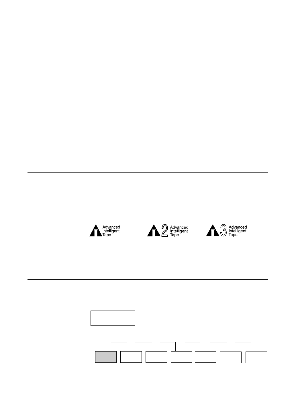
Data cartridges used with the SDX-D400C must be marked with the AIT-1,
logo. The SDX-D500C can be used with data cartridges marked with AIT-1
or AIT-2 logo. The SDX-D700C can be used with data cartridges marked
with the AIT-1, AIT-2, or AIT-3 logo.
Caution
Be sure to use only the cartridges designed specifically for AIT (do not use
8 mm cartridges for video).
System Components
The SDX-D700C/D500C/D400C connects to the host computer via on Ultra
Wide LVD/SE SCSI interface.
SDX-D700C/D500C/D400C
The SDX-D700C can connects to the host computer via a Ultra 160 SCSI
interface.
AIT-1 LOGO AIT-2 LOGO AIT-3 LOGO
Host Computer
Peripheral Devices
Figure 1-1. Example of System Components
Part 1. Introduction 7
Page 8
Part Names and Functions
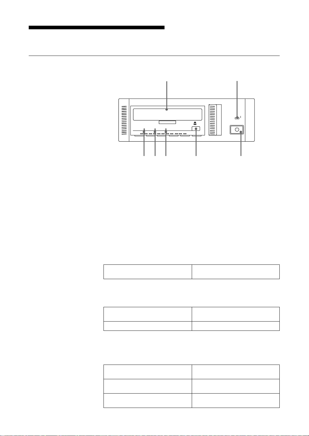
Front Panel (SDX-D500C/D400C)
12
BUSY TAPE STATUS
POWER
76543
Figure 1-2. Front panel
1 AIT Data Cartridge Receptacle
See page 14 for information on inserting and removing a AIT data
cartridge.
2 POWER Indicator
Lights while the drive is on.
3 BUSY Indicator
Lights when data is being transferred through the SCSI interface. This
indicator also lights under the following conditions:
Drive is reading or writing normally: repeated blinking (same on-off
interval).
4 TAPE Indicator
When a AIT cartridge is installed, this indicator lights. This also lights
under the following conditions:
Inserting and removing a cartridge: repeated blinking (same on-off
Cartridge deteriorated: alternating long-short blinking.
interval).
8 Part 1. Introduction
5 STATUS Indicator
Lights when an inserted cartridge is write-protected. This indicator also
lights under the following conditions:
Drive needs cleaning: repeating long-on, short-off
blinking.
End of Tape during cleaning: repeating blinking (same on-off
interval).
Drive Malfunctioning: repeating short-on (once or twice),
long-off blinking.
Page 9

6 EJECT Button
Push to remove a data cartridge from the drive.
7 POWER Switch
Press to turn the drive on or off.
Front Panel (SDX-D700C)
Refer to SDX-D500C/D400C front panel for unmarked parts.
1
Figure 1-3. Front panel
1 LED
The LED indicate the status of the SDX-D700C as follows.
TAPE MOTION
On - - Tape loaded
Slow flash - - Read/Write in
(0.9 sec on/0.3 sec off)
Fast flash - - Other tape access
(0.3 sec on/0.3 sec off)
-On -
-
- - On Media error
Fast flash Fast flash Fast flash
(0.3 sec on/0.3 sec off) (0.3 sec on/0.3 sec off) (0.3 sec on/0.3 sec off)
CLEANING REQUEST
Slow flash
(0.9 sec on/0.3 sec off)
REPLACE TAPE Meaning
progress
in progress
Cleaning
necessary
-
Cleaning not
complete
Hardware error
Part 1. Introduction 9
Page 10
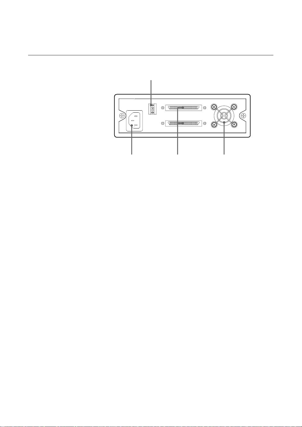
Rear Panel
1
243
Figure 1-4. Rear Panel
1 Rotary Selector Switch
SCSI ID selector.
2 AC IN Connector
Connect the supplied power cable here.
3 SCSI Connector
Connects to the SCSI bus connector of the host computer or another
SCSI peripheral.
10 Part 1. Introduction
4 Cooling Fan
Page 11
Part 2. Preparation
After you confirm that you have all of the required accessories for your
installation, connect the drive to the host computer, and select the SCSI ID
with the rotary switch on the rear panel.
Supplied Items
When you first open the box, make sure it contains the following items.
Contact your supplier if anything is missing or broken.
• AIT Drive Unit
• Power Cable
• Operator’s Guide
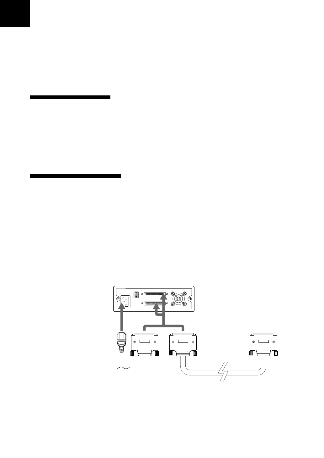
Interconnections
The SCSI bus allows connection of up to fifteen peripherals to the host
computer. Use a SCSI cable with a half pitch 68 pin connector.
Precautions
• Switch off the host computer and peripherals before connecting the SCSI
cable.
• Make sure the SCSI connectors are pressed tightly together.
• If this unit is the last (or only) device on the SCSI bus, make sure to connect
a SCSI bus terminator to the open connector.
• The total length of the SCSI cable(s) between the host computer and the last
device should be less than 12 meters.
AC power
Figure 2-1 Interconnections
*1
It should be less than 1.5 meters, if connected to single-ended SCSI host adaptor.
*1
Part 2. Preparation 11
Page 12
SCSI ID Setting
The SCSI ID is set by the rotary switch on the rear panel. Press the + or buttons to move the number up or down, respectively.
As shipped from the factory, the SCSI ID is set to 0. Press the switch buttons,
if necessary, to select the SCSI ID number you require.
Precautions
• The SCSI ID must be different from IDs of the other peripherals on the
SCSI bus.
• As shipped from the factory, Term power is ON. A SCSI bus terminator
must be connected to the SCSI bus before use.
• Before changing the SCSI ID setting, be sure to turn off the power with the
POWER switch on the front panel.
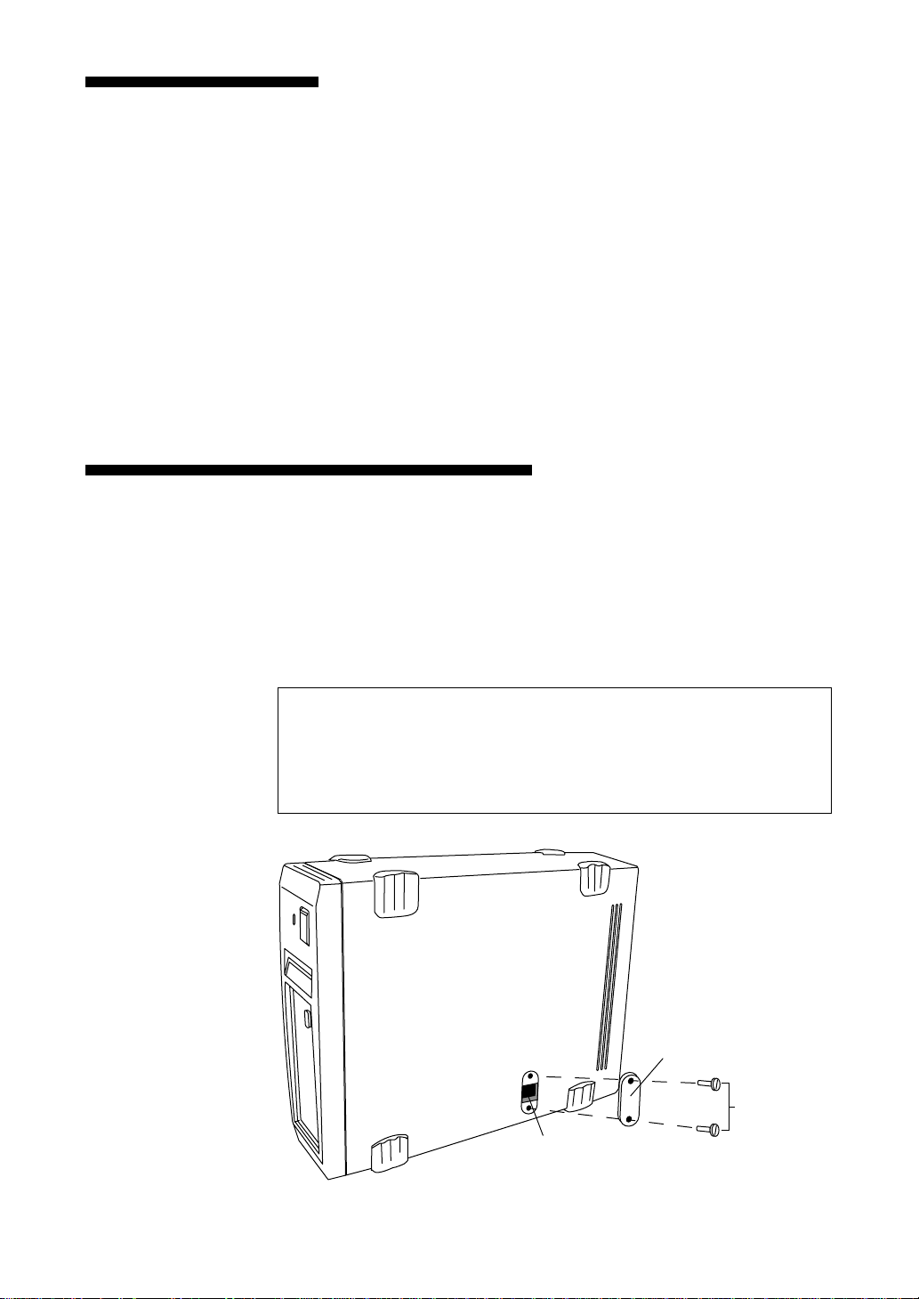
Option Switches (DIP Switch)
Remove the two slotted screws by using a slotted screwdriver. Remove the
access cover to change the DIP switch settings. (Refer to the following
figure for details changing the DIP switch settings.)
After changing the DIP switch settings, replace access cover and tighten the
two slotted screws using a slotted screwdriver.
CAUTION
Before removing the access cover to change DIP switch settings on the
drive, turn off the computer and disconnect the power cord from the unit.
Once the DIP switch settings have been changed, replace the access cover
using the two original slotted screws provided.
Access Cover
Slotted
Screws
DIP Switch
Figure 2-2. DIP Switch Access
12 Part 2. Preparation
Page 13

DIP Switch Positions
1 Reserved (OFF)
2 Reserved (OFF)
3 Reserved (OFF)
4 Reserved (OFF)
5 Terminator Power (ON)
6 Reserved (OFF)
7 DC Control (1) (ON)
Figure 2-3. DIP Switch Settings
8 DC Control (2) (OFF)
Data Compression Control DIP Switch
Data compression can be selected by DIP switches. Data compression is
enabled while position 7 [DC Control (1)] is ON. Control by host can be
disabled when position 8 [DC Control (2)] is ON.
Part 2. Preparation 13
Page 14

Part 3. Operation
This section describes how to use the AIT drive, and how to handle data
cartridges.
How to use the AIT Drive
1 Press the POWER switch on the front panel.
The POWER indicator should light, and the STATUS, BUSY and TAPE
indicators (with the SDX-D700C, the TAPE MOTION, CLEANING
REQUEST, and REPLACE TAPE indicators) should blink as the selftest is performed.
2 When the three indicators stop blinking, you can insert a data cartridge as
shown below. The TAPE indicator will blink, and if the cartridge is
write-protected, the STATUS indicator will light. (With the SDXD700C, even if the cartridge is write-protected, only the TAPE MOTION
indicator lights.)
14 Part 3. Operation
Figure 3-1. Inserting a data cartridge
3 Computer software controls the reading and writing of tapes. While
reading or writing, the BUSY indicator blinks. (With the SDX-D700C,
the TAPE MOTION indicator blinks.)
Page 15
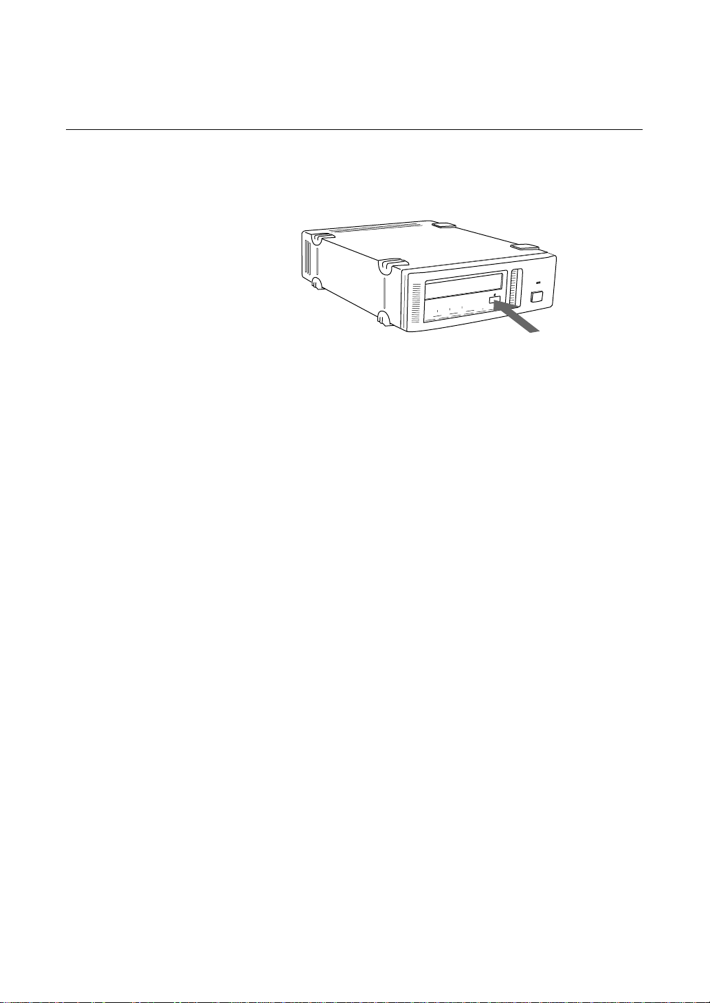
Cartridge Removal
Press the EJECT button.
The cartridge ejects automatically.
Figure 3-2. Press the EJECT button
Caution
Do not push the EJECT button while the BUSY indicator is blinking (with
the SDX-D700C, when the TAPE MOTION indicator is blinking) : to do so
may destroy data on the tape.
Part 3. Operation 15
Page 16

Part 4. Care and Maintenance
Taking Care of the Drive
Safety Considerations
■ Power
• Be sure to use only 100-240 V AC.
• Avoid plugging into the same outlet as high-current equipment like copiers
or shredders.
■ Power Cable Precautions
• Do not crush the cable or place heavy items on it. If the cable insulation
appears worn or broken, do not use the cable.
• Always unplug the cable by holding the plug: never pull the cable itself, as
it will break.
• If the drive is not being used for a long time, unplug the cable from the
outlet.
Avoiding Damage
■ Avoid shock and vibration
Intense shock, such as from dropping the drive, will damage it.
■ Environmental considerations
Do not store or use the drive in locations subject to:
• high humidity • excessive dust
• high temperature • intense vibration
• direct sunlight • sudden changes in temperature
■ Proper ventilation
To avoid overheating, install the drive where it will have free air circulation
around the case, and do not cover it during operation. The drive can
malfunction if the internal temperature rises too high.
■ Avoid sudden changes in temperature
If the drive is moved from a cool place to a warm place, or if the room
temperature suddenly rises, moisture may condense inside the case. After a
sudden change in temperature, wait at least one hour before turning the drive
on. If the drive is turned on with condensation inside, and a cartridge is
installed, the drive or the tape can be damaged.
16 Part 4. Care and Maintenance
Page 17

■ Abnormal occurrences
If the drive behaves abnormally, or if it begins to smell or smoke,
immediately unplug it from the wall outlet and contact your supplier for
assistance.
■ Cabinet cleaning
Wipe the cabinet with a soft dry cloth. For heavy dirt, wipe with a soft cloth
moistened with a gentle liquid soap, then wipe again with a soft dry cloth. Do
not use alcohol, paint thinner, bug sprays or other volatile solvents, as they
can damage the finish.
Part 4. Care and Maintenance 17
Page 18
Taking Care of Cartridges
Use Precautions
• Avoid heavy vibration and dropping.
• The shutter on the face of the cartridge is opened automatically when it is
inserted into the drive. Do not open the shutter by hand, as touching the tape
may damage it.
• The cartridge was carefully aligned during assembly at the factory. Please
do not try to open it or take it apart.
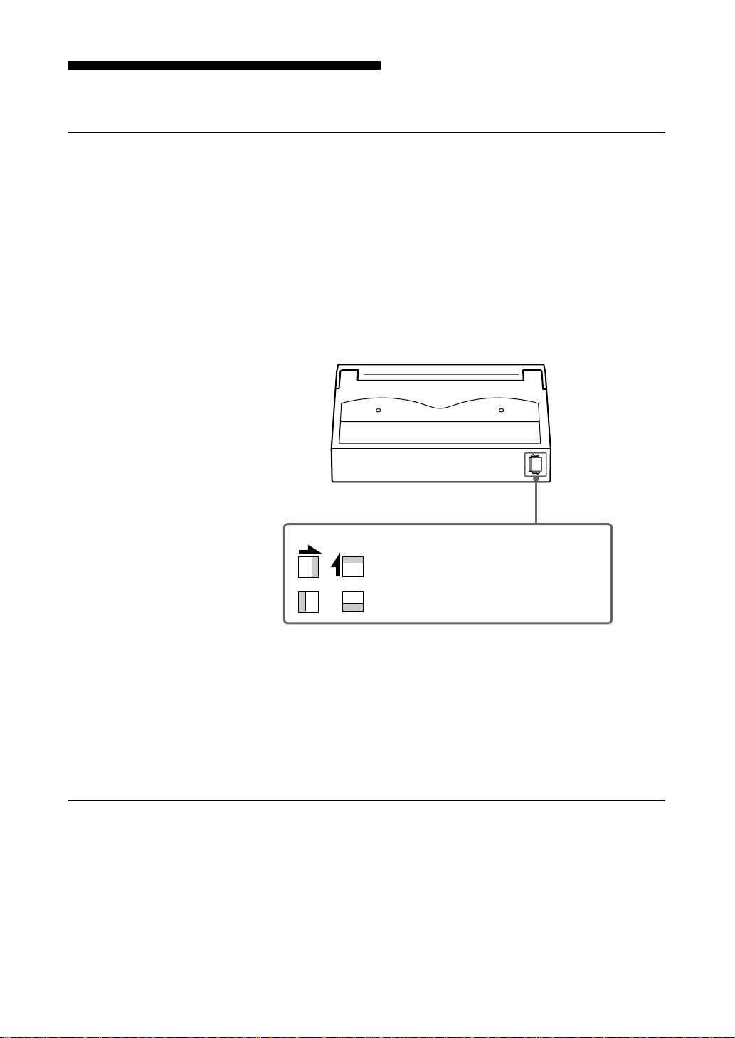
• The write-protect switch on the face of the cartridge prevents the tape from
being written to or accidentally erased. If you do not need to write to the
tape, move this switch to the write-protect position (in the direction of the
arrow).
• In case of a sudden change in temperature, condensation may interfere with
• Avoid unnecessary insertion and removal of cartridges if you do not need to
• When finished using the drive, remove the cartridge.
Storage Precautions
• Keep cartridges in their cases when not in the drive.
• Avoid storing cartridges in dusty places, in direct sunlight, near heaters or
• Do not place cartridges on the dashboard or in a storage tray in a car.
AIT-1 AIT-2, 3
Using your fingernail, push the switch in the
direction of the arrow to protect the tape
from writing or accidental erasure.
Return the switch to its original position to
re-enable writing.
Figure 4-1. Write-protect switch
reading and writing to a tape.
write or read a tape.
air conditioners, or in humid locations.
18 Part 4. Care and Maintenance
Page 19

Head Cleaning
To keep the AIT drive in top condition, clean the head as needed, using the
proper head cleaning cartridge (sold separately). When the head needs
cleaning, the STATUS indicator will blink.
With the SDX-D700C, the CLEANING REQUEST indicator will blink.
How to Clean
1 Load the head cleaning cartridge (SDX1-CL) into the AIT drive.
2 After about 15 seconds, cleaning will stop and the cartridge will eject
Notice
Do not rewind the cleaning cartridge and reuse it. When you reach the end of
the cartridge, dispose it and buy a new one.
Cleaning starts automatically.
automatically.
One head cleaning cartridge can be used about 30 times.
Part 4. Care and Maintenance 19
Page 20

Appendix
Specifications (SDX-D700C)
■ Performance
Storage Capacity 260 GB compressed
Bit Error Rate less than 10
Data Transfer Rate 12 MB/s uncompressed
(TAPE) 31.2 MB/s compressed
Burst Data Transfer Rate 12 MB/s maximum, asynchronous
(SCSI) 160 MB/s maximum, synchronous
Initialize Time less than 5 seconds
Load Time less than 24 seconds
Unload Time less than 30 seconds
Rewind Time less than 105 seconds (with 230 m tape)
■ Operating Environment
Operating Temperature: 10 to 35 °C
Non-Operating Temperature: –40 to +70 °C
■ Power Supply & Miscellaneous
(with 230 m AIT-3 tape)
100 GB uncompressed
(with 230 m AIT-3 tape)
-17
Humidity: 30 to 80%
Maximum wet bulb temperature: 26 °C
Humidity: 10 to 90%
*1
*1
(no condensation)
20 Appendix
Power Supply 100 to 240 V AC, 50/60 Hz
1.2 A
Case Dimensions 198 × 64.5 × 246 mm (W × H × D)
(excluding protruding parts)
Weight 2.4 kg
Accessories Power Cable (1)
Operator’s Guide (1)
Specifications may be subject to change, in the interest of technological
improvement, without notice or obligation.
*1
This is assuming 2.6 : 1 compression ratio.
The degree of data compression attained while recording data varies according to system
environment and data type.
Page 21

Specifications (SDX-D500C)
■ Performance
Storage Capacity 130 GB compressed
Bit Error Rate less than 10
Data Transfer Rate 6 MB/s uncompressed
(TAPE) 15.6 MB/s compressed
Burst Data Transfer Rate 12 MB/s maximum, asynchronous
(SCSI) 40 MB/s maximum, synchronous
Initialize Time less than 5 seconds
Load Time less than 24 seconds
Unload Time less than 30 seconds
Rewind Time less than 105 seconds (with 230 m tape)
■ Operating Environment
Operating Temperature: 10 to 35 °C
Non-Operating Temperature: –40 to +70 °C
■ Power Supply & Miscellaneous
(with 230 m AIT-2 tape)
*1
50 GB uncompressed
(with 230 m AIT-2 tape)
-17
*1
Humidity: 30 to 80%
(no condensation)
Maximum wet bulb temperature: 26 °C
Humidity: 10 to 90%
Power Supply 100 to 240 V AC, 50/60 Hz
1.2 A
Case Dimensions 198 × 64.5 × 246 mm (W × H × D)
(excluding protruding parts)
Weight 2.4 kg
Accessories Power Cable (1)
Operator’s Guide (1)
Specifications may be subject to change, in the interest of technological
improvement, without notice or obligation.
*1
This is assuming 2.6 : 1 compression ratio.
The degree of data compression attained while recording data varies according to system
environment and data type.
Appendix 21
Page 22

Specifications (SDX-D400C)
■ Performance
Storage Capacity 91 GB compressed
Bit Error Rate less than 10
Data Transfer Rate 4 MB/s uncompressed
(TAPE) 10.4 MB/s compressed
Burst Data Transfer Rate 12 MB/s maximum, asynchronous
(SCSI) 40 MB/s maximum, synchronous
Initialize Time less than 5 seconds
Load Time less than 24 seconds
Unload Time less than 30 seconds
Rewind Time less than 105 seconds (with 230 m tape)
■ Operating Environment
Operating Temperature: 10 to 35 °C
Non-Operating Temperature: –40 to +70 °C
■ Power Supply & Miscellaneous
(with 230 m AIT-1 tape)
*1
35 GB uncompressed
(with 230 m AIT-1 tape)
-17
*1
Humidity: 30 to 80%
(no condensation)
Maximum wet bulb temperature: 26 °C
Humidity: 10 to 90%
22 Appendix
Power Supply 100 to 240 V AC, 50/60 Hz
1.2 A
Case Dimensions 198 × 64.5 × 246 mm (W × H × D)
(excluding protruding parts)
Weight 2.4 kg
Accessories Power Cable (1)
Operator’s Guide (1)
Specifications may be subject to change, in the interest of technological
improvement, without notice or obligation.
*1
This is assuming 2.6 : 1 compression ratio.
The degree of data compression attained while recording data varies according to system
environment and data type.
Page 23

Règles de sécurité
Informations spécifiques de l’utilisateur
Les numéros du modèle et de série sont situés sous l’appareil. Inscrivez les
numéros de série dans l’espace prévu ci dessous.
Reférez vous y chaque fois que vous appelez votre revendeur Sony à propos
de ce matériel.
No de modèle No de série
Informations
AVERTISSEMENT
Afin éviter tout risque d’incendie ou d’électrocution,
ne pas exposer cet appareil à la pluie ou à l’humidité.
Pour éviter une électrocution,ne tentez pas d’ouvrir le
module.
Confier l’entretien à un spécialiste uniquement.
Aux utilisateurs vivant aux U.S.A.
Veuillez noter que tout changement ou modification apportés, non
expressément autorisés dans ce manuel pourraient vous priver de votre droit
d’utilisation de ce matériel.
Français
AVERTISSEMENT
Remarque: Remarque: Ce matériel après tests satisfait aux normes des
équipements digitaux de la classe B, conformément au chapitre 15 de la
réglementation de la FCC. Ces normes ont pour objet d’assurer une
protection raisonnable contre des interférences parasites dans une installation
domestique. Ce matériel produit, utilise et peut émettre des ondes-radio. Il
peut donc parasiter des communications radio s’il n’est pas installé et utilisé
selon les instructions. Cependant il n’y a aucune garantie que ces
interférences ne puissent se produire au sein d’une installation domestique. Si
cet équipement venait à parasiter la réception des émissions de radio ou de
télévision, ce qui peut être déterminé en allumant puis en éteignant le
module, l’utilisateur est encouragé à essayer de corriger ces interférences en
respectant les mesures suivantes:
• Orienter différemment ou déplacer l’antenne réceptrice.
• Eloigner davantage le module de l’appareil récepteur.
• Brancher le module sur une prise reliée à un circuit différent de celui de
l’appareil récepteur.
• Si besoin, prenez conseil auprès de votre distributeur ou d’un technicien
radio/TV expérimenté.
Règles de sécurité 23
Page 24

NOTIFICATION
CETTE NOTIFICATION EST VALABLE AUX U.S.A ET CANADA
UNIQUEMENT
Pour les U.S.A, utiliser le cordon-secteur 220-240V type UL décrit cidessous Pour le CANADA, utiliser le cordon-secteur 220-240V certifié
SA, décrit ci-dessous
N’UTILISER AUCUN AUTRE CORDON D’ALIMENTATION.
Branchement Prise bi-polaire avec mise à la terre
(Configuration NEMA 6-15P)
Cordon Type SVT ou SJT, trois fils AWG de section 18.
Longueur Maximum 14.7 feet (4.5m)
Valeur Minimale 10A, 250 V
NOTIFICAT ION
La notification qui suit est valable pour les pays autres que les U.S.A et le
Canada.
Dans les pays autres que les U.S.A et le Canada, utiliser le cordon-secteur
approuvé par les organismes ayant autorité dans chacun des pays concernés.
24 Règles de sécurité
Page 25

Table des matières
Utilisation de ce guide .................................................................... 26
Partie 1.
Introduction
Partie 2.
Préparatifs
Partie 3.
Fonctionnement
Partie 4.
Entretien et
réparation
A propos des lecteurs AIT.............................................................. 27
Caractéristiques .....................................................................................27
Cassettes utilisables ...............................................................................28
Composants du système ........................................................................ 28
Nomenclature .................................................................................. 29
Panneau avant (SDX-D500C/D400C)...................................................29
Panneau avant (SDX-D700C) ...............................................................30
Panneau arrière ...................................................................................... 31
Articles fournis................................................................................ 32
Interconnexions .............................................................................. 32
Réglage SCSI ID .............................................................................. 33
Commutateurs d’option (Commutateur DIP)................................ 33
Utilisation du lecteur AIT................................................................ 35
Retrait d’une cassette.............................................................................36
Manipulation du lecteur.................................................................. 37
Sécurité ..................................................................................................37
Eviter tout dommage .............................................................................37
Entretien des cassettes .................................................................. 39
Précautions d’utilisation ........................................................................ 39
Précautions pour le rangement ..............................................................39
Nettoyage de la tête de lecture ...................................................... 40
Méthode de nettoyage............................................................................40
Annexe
Spécifications (SDX-D700C)........................................................... 41
Spécifications (SDX-D500C)........................................................... 42
Spécifications (SDX-D400C)........................................................... 43
Table des matières 25
Page 26

Utilisation de ce guide
Ce guide décrit le lecteur AIT SDX-D700C/D500C/D400C et sa
manipulation. Prière de le lire attentivement avant d’utiliser le lecteur et de le
garder à portée de main pour toute référence ultérieure.
Ce guide est composé de quatre parties, plus les spécifications. Se reporter
aux chapitres relatifs pour chaque utilisation spécifique.
Partie 1 : décrit les caractéristiques du lecteur, les composants de son
système et sa nomenclature.
Partie 2 : décrit les connexions nécessaires entre le lecteur et l’ordinateur
central. Si d’autres périphériques SCSI sont utilisés, il faudra probablement
modifier le réglage SCSI ID. Lire cette partie pour installer le lecteur.
Partie 3 : décrit l’utilisation du lecteur, y compris sa mise sous tension ainsi
que l’insertion et le retrait des cassettes. Lire cette partie pour faire
fonctionner le lecteur.
Partie 4 : décrit l’entretien du lecteur et des cassettes et la méthode de
nettoyage des têtes de lecture. A lire avant d’utiliser le lecteur.
L’annexe, Spécifications donne les principales caractéristiques SDX-
D700C/D500C/D400C.
26 Utilisation de ce guide
Page 27

Partie 1. Introduction
A propos des lecteurs AIT
Le SDX-D700C est un lecteur AIT externe qui utilise des cassettes de
données conformes au format AIT-3. Le SDX-D500C est un lecteur AIT
externe qui utilise des cassettes de données conformes au format AIT-2. Le
SDX-D400C est un lecteur AIT externe qui utilise des cassettes de données
conformes au format AIT-1. Le SDX-D700C accepte les formats AIT-1,
AIT-2 et AIT-3. Le SDX-D500C accepte les formats AIT-1 et AIT-2. Le
SDX-D400C accepte seulement le format AIT-1.
Caractéristiques
Le lecteur AIT SDX-D700C possède les caractéristiques suivantes :
• Le format évolué AIT permet une grande capacité d’enregistrement sur les
cassettes de données AIT-1/AIT-2/AIT-3.
• La fonction lecture après écriture et le code de correction d’erreur de niveau
trois garantissent une grande fiabilité des données.
• La compression des données permet un enregistrement de 260 Gigaoctets
sur une cassette de 230 m de long.
La capacité d’origine est de 100 Gigaoctets pour une cassette de 230 m de
long.
• Les données enregistrées sont automatiquement vérifiées pour la
compression.
• L’interface Ultra 160 SCSI LVD/SE est entièrement compatible pour
l’accès à l’ordinateur central.
• L’opération de lecture/écriture est possible pour les formats AIT-1, AIT-2 et
AIT-3.
*1
Le lecteur AIT SDX-D500C possède les caractéristiques suivantes :
• Le format évolué AIT permet une grande capacité d’enregistrement sur les
cassettes de données AIT-1/AIT-2.
• La fonction lecture après écriture et le code de correction d’erreur de niveau
trois garantissent une grande fiabilité des données.
• La compression des données permet un enregistrement de 130 Gigaoctets
sur une cassette de 230 m de long.
*1
La capacité d’origine est de 50 Gigaoctets pour une cassette de 230 m de
long.
• Les données enregistrées sont automatiquement vérifiées pour la
compression.
• L’interface SCSI Ultra large LVD/SE est entièrement compatible pour
l’accès à l’ordinateur central.
• L’opération de lecture/écriture est possible pour les formats AIT-1 et AIT-2.
*1
Ceci suppose un taux de compression de 2.6 : 1.
Le degré du taux de compression des données atteint pendant l’enregistrement varie en
fonction de l’environnement système et du type de données.
Partie 1. Introduction 27
Page 28

Le lecteur AIT SDX-D400C possède les caractéristiques suivantes :
• Le format évolué AIT permet une grande capacité d’enregistrement sur les
• La fonction lecture après écriture et le code de correction d’erreur de niveau
• La compression des données permet un enregistrement de 91 Gigaoctets sur
• Les données enregistrées sont automatiquement vérifiées pour la
• L’interface SCSI Ultra large LVD/SE est entièrement compatible pour
• L’opération de lecture/écriture est possible pour le format AIT-1.
*1
Cassettes utilisables
Les cassettes de données utilisées avec le SDX-D400C doivent être
identifiées par le logo AIT-1.
Le SDX-D500C peut être utilisé avec les cassettes de données identifiées par
le logo AIT-1 ou AIT-2. Le SDX-D700C peut être utilisé avec les cassettes
de données identifiées par le logo AIT-1, AIT-2 ou AIT-3.
cassettes de données AIT-1.
trois garantissent une grande fiabilité des données.
une cassette de 230 m de long.
*1
La capacité d’origine est de 35 Gigaoctets pour une cassette de 230 m de
long.
compression.
l’accès à l’ordinateur central.
Ceci suppose un taux de compression de 2.6 : 1.
Le degré du taux de compression des données atteint pendant l’enregistrement varie en
fonction de l’environnement système et du type de données.
LOGO AIT-1 LOGO AIT-2 LOGO AIT-3
Précaution
Faire attention à n’utiliser que les cassettes spécifiquement conçues pour AIT
(ne pas utiliser les cassettes vidéo 8 mm).
Composants du système
Le SDX-D700C/D500C/D400C se raccorde à l’ordinateur central via une
interface SCSI Ultra large LVD/SE.
Ordinateur central
SDX-D700C/D500C/D400C
Le SDX-D700C se raccorde à l’ordinateur central via une interface SCSI
Ultra 160.
28 Partie 1. Introduction
Figure 1-1 Exemple de composants du système
Périphériques
Page 29

Nomenclature
Panneau avant (SDX-D500C/D400C)
12
BUSY TAPE STATUS
POWER
76543
Figure 1-2. Panneau avant
1 Réceptacle de cassette de données AIT
Voir la page 14 pour les informations sur l’insertion et le retrait d’une
cassette de données AIT.
2 Voyant POWER
S’allume lorsque le lecteur est sous tension.
3 Voyant BUSY
S’allume lorsque les données sont en cours de transfert via l’interface
SCSI. Ce voyant s’allume aussi dans les situations suivantes :
Le lecteur lit ou écrit de façon
normale :
4 Voyant TAPE
Lorsqu’une cassette AIT est installée, ce voyant s’allume. Ce voyant
s’allume aussi dans les situations suivantes :
Insertion et retrait d’une cassette :
Cassette détériorée :
Clignotements répétés (intervalles
réguliers).
Clignotements répétés (intervalles réguliers)
Clignotements alternés longs-
courtspadeo largo y corto alternativo.
5 Voyant STATUS
S’allume lorsqu’une cassette insérée est protégée contre l’écriture. Ce
voyant s’allume aussi dans les situations suivantes :
Le lecteur nécessite un nettoyage :
Signal de fin de bande en cours de
nettoyage :
Défaut de fonctionnement du
lecteur :
Clignotements répétés longs allumés –
courts éteints.
Clignotements répétés (intervalles
réguliers).
Clignotements répétés courts allumés
(une ou deux fois) suivis de
clignotement long éteint.
Partie 1. Introduction 29
Page 30

6 Bouton EJECT
Appuyer pour retirer une cassette de données du lecteur.
7 Interrupteur POWER
Appuyer pour mettre le lecteur sous ou hors tension.
Panneau avant (SDX-D700C)
Se reporter au panneau avant du SDX-D500C/D400C pour les parties non
indiquées.
1
Figure 1-3. Panneau avant
1 LED
La LED indique l’état du SDX-D700C comme suit.
Mouvement de la bande
On - - Bande chargée
Clignotement lent
(0.9 sec on/0.3 sec off)
Clignotement rapide
(0.3 sec on/0.3 sec off)
-On -
-
- - On Erreur support
Clignotement rapide Clignotement rapide Clignotement rapide
(0.3 sec on/0.3 sec off) (0.3 sec on/0.3 sec off) (0.3 sec on/0.3 sec off)
Demande de nettoyage Remplacer la bande Signification
--
--
Clignotement lent
(0.9 sec on/0.3 sec off)
-
Lecture/écriture
en cours
Accès d’une
bande en cours
Nettoyage
nécessaire
Nettoyage non
terminé
Erreur progiciel
30 Partie 1. Introduction
Page 31

Panneau arrière
1
243
Figure 1-4. Panneau arrière
1 Sélecteur rotatif
Sélecteur d’identification SCSI ID.
2 Connecteur AC IN
Brancher le câble d’alimentation fourni dans ce connecteur.
3 Connecteur SCSI
A brancher au connecteur de bus SCSI de l’ordinateur central ou d’un
autre périphérique SCSI.
4 Ventilateur
Partie 1. Introduction 31
Page 32

Partie 2. Préparatifs
Après avoir vérifié tous les accessoires nécessaires à l’installation, raccorder
le lecteur à l’ordinateur central et sélectionner le SCSI ID à l’aide du
sélecteur rotatif sur le panneau arrière.
Articles fournis
A l’ouverture du paquet, vérifier qu’il contient les articles suivants.
Si un article est manquant ou cassé, contacter le fournisseur.
• Lecteur AIT
• Câble d’alimentation
• Guide de l’utilisateur
Interconnexions
Le bus SCSI permet de raccorder jusqu’à quinze périphériques à l’ordinateur
central. Utiliser un câble SCSI muni d’un connecteur à 68 broches.
Précautions
• Mettre l’ordinateur central et les périphériques hors tension avant de
connecter le câble SCSI.
• S’assurer que les connecteurs SCSI sont bien serrés ensemble.
• Si le lecteur est le dernier (ou le seul) périphérique sur le bus SCSI,
s’assurer de raccorder une terminaison de bus SCSI au connecteur libre.
• La longueur totale du(des) câble(s) SCSI entre l’ordinateur central et le
dernier périphérique doit être inférieure à 12 mètres.
Alimentation AC
Figure 2-1 Interconnexions
*1
32 Partie 2. Préparatifs
*1
Elle doit être inférieure à 1,5 mètres pour une connexion à un adaptateur central SCSI à
terminaison unique.
Page 33

Réglage SCSI ID
Le SCSI ID se règle à l’aide du sélecteur rotatif sur le panneau arrière.
Appuyer sur les touches + ou – pour faire défiler les chiffres respectivement
vers le haut ou le bas.
Au départ d’usine, le SCSI ID est réglé sur 0. Si besoin, appuyer sur les
touches pour sélectionner le numéro SCSI ID souhaité.
Précautions
• Le SCSI ID doit être différent des ID des autres périphériques sur le bus
SCSI.
• Au départ d’usine, l’alimentation Term est sur ON. Une terminaison de bus
SCSI doit être raccordée au bus SCSI avant l’utilisation.
• Avant de modifier le réglage SCSI ID, s’assurer de mettre l’appareil hors
tension à l’aide de l’interrupteur POWER sur le panneau avant.
Commutateurs d’option (Commutateur DIP)
Déplacer les deux vis à fente en utilisant un tournevis approprié. Retirer le
couvercle d’accès pour modifier les réglages de commutateur DIP. (Se
reporter à la figure suivante pour les détails sur la modification des réglages
du commutateur DIP).
Une fois les réglages du commutateur DIP modifiés, remettre le couvercle
d’accès et serrer les deux vis à fente à l’aide du tournevis approprié.
Précaution
Avant de retirer le couvercle d’accès pour modifier les réglages du
commutateur DIP dans le lecteur, mettre l’ordinateur hors tension et
débrancher le cordon d’alimentation de l’appareil.
Une fois les réglages du commutateur DIP modifiés, remettre le couvercle
d’accès à l’aide des deux vis à fente d’origine.
Couvercle d’accès
Vis à fente
Commutateur DIP
Figure 2-2. Accès au commutateur DIP
Partie 2. Préparatifs 33
Page 34

Positions du commutateur DIP
1 Reservé (OFF)
2 Reservé (OFF)
3 Reservé (OFF)
4 Reservé (OFF)
5 Terminaison alimentation (ON)
6 Reservé (OFF)
7 Contrôle DC (1) (ON)
Figure 2-3. Réglages du commutateur DIP
8 Contrôle DC (2) (OFF)
Commutateur DIP de contrôle de compression de données
La compression de données peut être sélectionnée par les commutateurs DIP.
La compression de données est disponible lorsque la position 7 [DC Control
(1)] est ON. Le contrôle par l’ordinateur central peut être désactivé lorsque la
position 8 [DC Control (2)] est ON.
34 Partie 2. Préparatifs
Page 35

Partie 3. Fonctionnement
Cette section décrit l’utilisation du lecteur AIT ainsi que la manipulation des
cassettes de données.
Utilisation du lecteur AIT
1 Appuyer sur l’interrupteur POWER du panneau avant.
Le voyant POWER doit s’allumer tandis que les voyants STATUS,
BUSY et TAPE (avec le SDX-D700C, les voyants TAPE MOTION,
CLEANING REQUEST et REPLACE TAPE) doivent clignoter pendant
le déroulement de l’autotest.
2 Lorsque les trois voyants s’arrêtent de clignoter, il est possible d’insérer
une cassette de données tel qu’indiqué ci-dessous. Le voyant TAPE
clignote et si la cassette est protégée contre l’écriture, le voyant STATUS
s’allume. (Pour le SDX-D700C, même lorsque la bande est protégée
contre l’écriture, seul le voyant TAPE MOTION s ‘allume).
Figure 3-1. Insertion d’une cassette de données
3 Le logiciel de l’ordinateur contrôle la lecture et l’écriture des bandes.
Pendant les opérations de lecture ou d’écriture, le voyant BUSY clignote
(Avec le SDX-D700C, le voyant TAPE MOTION clignote.)
Partie 3. Fonctionnement 35
Page 36

Retrait d’une cassette
Appuyer sur le bouton EJECT.
La cassette est automatiquement éjectée.
Précaution
Ne pas appuyer sur le bouton EJECT lorsque le voyant BUSY (Avec le SDXD700C, lorsque le voyant TAPE MOTION clignote.) clignote au risque de
détruire les données sur la bande.
Figure 3-2. Appuyer sur le bouton EJECT
36 Partie 3. Fonctionnement
Page 37

Partie 4. Entretien et réparation
Manipulation du lecteur
Sécurité
■ Alimentation électrique
• S’assurer de n’utiliser que du courant alternatif 100-240 V AC.
• Eviter de brancher le lecteur sur la même prise que des appareils à forte
intensité électrique tel que des photocopieurs ou des destructeurs de
documents.
■ Précautions pour le câble d’alimentation
• Ne pas écraser le câble ou placer d’objet lourd dessus. Si l’isolation du
câble apparaît abîmée ou cassée, ne pas utiliser le câble.
• Débrancher toujours le câble en le tenant par la prise : ne pas tirer sur le
câble lui-même au risque de le casser.
• Si le lecteur n’est pas utilisé pendant longtemps, le débrancher de la prise
murale.
Eviter tout dommage
■ Eviter les chocs et les vibrations
Un choc violent, tel que la chute du lecteur, risque de l’endommager.
■ Conditions d’environnement
Ne pas utiliser ou ranger le lecteur dans des endroits soumis à :
• une forte humidité•de la poussière excessive
• une température élevée • des vibrations fortes
• la lumière directe du soleil • des changements brusques de
■ Ventilation adéquate
Pour éviter toute surchauffe, installer le lecteur dans un endroit avec une
bonne circulation d’air autour du boîtier et ne pas le couvrir pendant
l’utilisation. Le lecteur risque d’être endommagé si la température interne
augmente beaucoup.
■ Eviter les changements brusques de température
Si le lecteur est déplacé d’un endroit frais à un endroit chaud ou si la
température de la pièce augmente soudainement, de l’humidité risque de se
condenser dans le boîtier. Attendre au moins une heure avant de mettre le
lecteur sous tension lorsqu’il y a un changement brusque de température. Si
le lecteur est mis sous tension avec de l’humidité condensée dedans et si une
cassette est installée, le lecteur ou la cassette risquent d’être endommagés.
température
Partie 4. Entretien et réparation 37
Page 38

■ Conditions anormales
Si le lecteur ne fonctionne pas correctement ou qu’il commence à dégager
une odeur ou de la fumée, le débrancher immédiatement de la prise murale et
contacter le fournisseur pour assistance.
■ Nettoyage du coffret
Nettoyer le coffret avec un chiffon doux et sec. Pour nettoyer les taches
importantes, essuyer avec un chiffon doux humidifié d’une solution
savonneuse neutre, puis sécher avec un chiffon doux et sec. Ne pas utiliser
d’alcool, de diluant pour peinture, de l’insecticide ou tout autre solvant
volatile qui pourraient abîmer la finition de l’appareil.
38 Partie 4. Entretien et réparation
Page 39

Entretien des cassettes
Précautions d’utilisation
• Eviter les fortes vibrations et les chutes.
• L’obturateur à l’avant de la cassette s’ouvre automatiquement lorsqu’elle
est insérée dans le lecteur. Ne pas ouvrir l’obturateur à la main car le
contact avec la bande risque de l’endommager.
• La cassette a été soigneusement alignée pendant l’assemblage à l’usine. Ne
pas essayer de l’ouvrir ou de la démonter.
• Le commutateur de protection contre l’écriture empêche l’écriture ou
l’effacement accidentels de la bande. S’il n’y a pas besoin d’enregistrer sur
la bande, déplacer le commutateur sur la position de protection contre
l’écriture (dans la direction de la flèche).
AIT-1 AIT-2, 3
Figure 4-1. Commutateur de protection contre l’écriture
• Eviter toute insertion ou retrait inutiles des cassettes s’il n’y a pas besoin de
lire ou d’enregistrer une bande.
• Eviter d’insérer et de retirer inutilement les cassettes s’il n’y a pas le besoin
d’enregistrer ou de lire une bande.
• Retirer la cassette à la fin de l’utilisation du lecteur.
Précautions pour le rangement
• Conserver les cassettes dans leurs boîtiers de rangement lorsqu’elles ne sont
pas dans le lecteur.
• Eviter de ranger les cassettes dans des endroits poussiéreux, à proximité
d’un chauffage ou d’un climatiseur ou soumis à l’humidité.
• Ne pas laisser les cassettes sur le tableau de bord ou dans la boîte à gants
d’une voiture.
Pousser le curseur avec l’ongle dans la
direction de la flèche pour protéger la bande
de l’écriture ou l’effacement accidentels.
Remettre le curseur dans sa position initiale
pour permettre l’écriture.
Partie 4. Entretien et réparation 39
Page 40

Nettoyage de la tête de lecture
Pour conserver le lecteur AIT dans la meilleure condition possible, nettoyer
la tête régulièrement à l’aide de la cartouche de nettoyage appropriée (vendue
séparément). Le voyant STATUS clignote lorsque la tête nécessite un
nettoyage.
Avec le SDX-D700C, le voyant CLEANING REQUEST clignote.
Méthode de nettoyage
1 Introduire la cartouche de nettoyage de tête (SDX1-CL) dans le lecteur
AIT.
Le nettoyage commence automatiquement.
2 Après environ 15 secondes, le nettoyage s’arrête et la cartouche est
automatiquement éjectée.
Une cartouche de nettoyage peut être utilisée environ 30 fois.
Remarque
Ne pas rembobiner la cartouche de nettoyage et ne pas la réutiliser. Lorsque
la cartouche est en fin de bande, il faut la jeter et acheter une autre.
40 Partie 4. Entretien et réparation
Page 41

Annexe
Spécifications (SDX-D700C)
■ Performance
Capacité d’enregistrement 260 GB compressés
Taux d’erreur de bit inférieur à 10
Vitesse de transfert des données 12 MB/S sans compression
(BANDE) 31,2 MB/S avec compression
Vitesse de transfert des données en rafale
(SCSI) 160 MB/S maximum, synchrone
Durée d’initialisation inférieure à 5 secondes
Durée de chargement inférieure à 24 secondes
Durée de déchargement inférieure à 30 secondes
Durée de rembobinage inférieure à 105 secondes
■ Environnement de fonctionnement
En fonctionnement Température : de 10 à 35 °C
Hors fonctionnement Température : de -40 à +70 °C
(avec une bande AIT-3 de 230 m)
*1
100 GB sans compression
(avec une bande AIT-3 de 230 m)
-17
*1
12 MB/S maximum, asynchrone
(avec une bande de 230m)
Humidité: de 30 à 80%
(sans condensation)
Température maximale au thermomètre
mouillé : 26 °C
Humidité: de 10 à 90%
■ Alimentation électrique et divers
Alimentation électrique de 100 à 240 V AC, 50/60 Hz
Dimensions du boîtier 198 × 64.5 × 246 mm (L × H × P)
Poids 2,4 kg
Accessoires Câble d’alimentation (1)
Les spécifications peuvent être sujettes à des modifications dans l’intérêt du
progrès technologique, sans notification ou obligation.
*1
Ceci suppose un taux de compression de 2.6 : 1.
Le degré de compression des données atteint pendant l’enregistrement varie en fonction de
l’environnement système et du type de données.
1,2 A
(à l’exclusion des pièces saillantes)
Guide de l’utilisateur (1)
Annexe 41
Page 42

Spécifications (SDX-D500C)
■ Performance
Capacité d’enregistrement 130 GB compressés
Taux d’erreur de bit inférieur à 10
Vitesse de transfert des données 6 MB/S sans compression
(BANDE) 15.6 MB/S avec compression
Vitesse de transfert des données en rafale
(SCSI) 40 MB/S maximum, synchrone
Durée d’initialisation inférieure à 5 secondes
Durée de chargement inférieure à 24 secondes
Durée de déchargement inférieure à 30 secondes
Durée de rembobinage inférieure à 105 secondes
■ Environnement de fonctionnement
En fonctionnement Température : de 10 à 35 °C
Hors fonctionnement Température : de -40 à +70 °C
(avec une bande AIT-2 de 230 m)
*1
50 GB sans compression
(avec une bande AIT-2 de 230 m)
-17
*1
12 MB/S maximum, asynchrone
(avec une bande de 230m)
Humidité: de 30 à 80%
(sans condensation)
Température maximale au thermomètre
mouillé : 26 °C
Humidité: de 10 à 90%
■ Alimentation électrique et divers
Alimentation électrique de 100 à 240 V AC, 50/60 Hz
Dimensions du boîtier 198 × 64.5 × 246 mm (L × H × P)
Poids 2,4 kg
Accessoires Câble d’alimentation (1)
Les spécifications peuvent être sujettes à des modifications dans l’intérêt du
progrès technologique, sans notification ou obligation.
*1
Ceci suppose un taux de compression de 2.6 : 1.
Le degré de compression des données atteint pendant l’enregistrement varie en fonction de
l’environnement système et du type de données.
42 Annexe
1,2 A
(à l’exclusion des pièces saillantes)
Guide de l’utilisateur (1)
Page 43

Spécifications (SDX-D400C)
■ Performance
Capacité d’enregistrement 91 GB compressés
Taux d’erreur de bit inférieur à 10
Vitesse de transfert des données 4 MB/S sans compression
(BANDE) 10.4 MB/S avec compression
Vitesse de transfert des données en rafale
(SCSI) 40 MB/S maximum, synchrone
Durée d’initialisation inférieure à 5 secondes
Durée de chargement inférieure à 24 secondes
Durée de déchargement inférieure à 30 secondes
Durée de rembobinage inférieure à 105 secondes
■ Environnement de fonctionnement
En fonctionnement Température : de 10 à 35 °C
Hors fonctionnement Température : de -40 à +70 °C
(avec une bande AIT-1 de 230 m)
*1
35 GB sans compression
(avec une bande AIT-1 de 230 m)
-17
*1
12 MB/S maximum, asynchrone
(avec une bande de 230m)
Humidité: de 30 à 80%
(sans condensation)
Température maximale au thermomètre
mouillé : 26 °C
Humidité: de 10 à 90%
■ Alimentation électrique et divers
Alimentation électrique de 100 à 240 V AC, 50/60 Hz
Dimensions du boîtier 198 × 64.5 × 246 mm (L × H × P)
Poids 2,4 kg
Accessoires Câble d’alimentation (1)
Les spécifications peuvent être sujettes à des modifications dans l’intérêt du
progrès technologique, sans notification ou obligation.
*1
Ceci suppose un taux de compression de 2.6 : 1.
Le degré de compression des données atteint pendant l’enregistrement varie en fonction de
l’environnement système et du type de données.
1,2 A
(à l’exclusion des pièces saillantes)
Guide de l’utilisateur (1)
Annexe 43
Page 44

Sicherheitsvorschriften
Dokument des Inhabers
Die Modell-und die Serienummern befinden sich auf der Linie unten.
Schreiben Sie die Seriennummer auf die vorgegebene Linie. Erwaehenen sie
diese wenn Sie Ihren Sony Haendler wegen dieses Produktes kontaktieren.
Modell Nr. Serie Nr.
Information
WARNUNG
Setzen Sie die Einheit nicht Regen oder Feuchtigkeit
aus um Feuer- oder Schockgefahr vorzubeugen.
Oeffnen Sie das Gehaeuse nicht um elektrischen
Schock zu vermeiden. Konsultieren Sie nur
qualifiziertes Personal um Dienstleistungen.
Fuer Kunden in den U. S. A.
Seien Sie ermahnt dass jedwelche Veraender oder Modifizierungen welche
nicht ausdrueklich in dieser Anleitung genehmigt sind Ihre Befugnis zur
Bedienung dieser Einheit gefaehreden koennte.
WARNUNG
Bemerkung: Dieses Geraet erfuellt die Bedingungen unter den
Beschraenkungen fuer digitale Geraete Klasse B gemaess Teil 15 der FCC
Regeln. Diese Beschraenkungen sollen fuer angemessenen Schtuz gegen
schaedliche Stoerungen in einer Wohninstallation sorgen. Dieses Geraet
erzeugt und verbraucht Radiofrequenzenergie und kann diese auch ausstrahlen,
welche bei falscher Installierung, die nicht gemaess der Anleitungen erfolgt,
schaedliche Stoerungen mit Radiokommunikation erzeugen koennte. Es kann
nicht garantiert werden dass Stoerungen in einer bestimmten Installation nicht
erfolgen werden. Falls diese Ausstattung schaedliche Stoerungen zu Radiooder Televisionempfang bereitet, sind die Benutzer ermutigt, einen oder
mehrere der folgenden Massnahmen zu ergreifen:
• Richten Sie die Empfangsantenne neu aus oder verlegen Sie dieselbe.
• Vergroessern Sie den Abstand zwischen der Ausstattung und dem
Empfaenger.
• Verbinden Sie die Ausstattung in eine Steckdose mit einem anderen
Stromkreis als jener mit welcher der Empfaenger verbunden ist.
• Fragen Sie Ihren Fachmann oder einen erfahrenen Radio/TV Techniker
um Hilfe.
44 Sicherheitsvorschriften
Page 45

• Diese Ausrüstung erfüllt die Europäischen EMC-Bestimmungen für die
Verwendung in folgender/folgenden Umgebung(en):
- Wohngegenden
- Gewerbegebiete
- Leichtindustriegebiete
(Diese Ausrüstung erfüllt die Bestimmungen der Norm EN 55022,
Klasse B)
ACHTUNG
Zur trehnung vom Netz ist der Netzseeker Aus der steckdose zu ziehen,
welche sich in der Nähe des Gerätes befinden muâ und leicht zugärlich sein
soll.
Hinweis: Der höchste schalldruckpegal beträgt 70 db (A) oder weniger
gemaâ ISO 7779.
BEMERKUNG
DIESE BEMERKUNG BEZIEHT SICH NUR AUF DIE USA UND
KANADA.
Falls in die USA geliefert, gebrauchen Sie das UL LISTED Stromkabel in
der Beschreibung unten fuer 220-240 V Bedienung.
Falls nach Kanada geliefert, gebrauchen Sie das CSA CERTIFIED
Stromkabel in der Beschreibung unten fuer 220-240 V Bedienung.
GEBRAUCHEN SIE KEINE ANDERE SORTE STROMKABEL
Deutsch
Steckerkappe Tandemblatt mit Bodenkontaktstift.
(NEMA 6-15P Konfiguration)
Kabel Typ SVT oder SJT, drei 18 AWG Kabel.
Laenge Maximum 4.5m
Messung Minimum 10A, 250V
BEMERKUNG
Diese Bemerkung ist fuer andere Laender als die USA und Kanada
angebracht.
In anderen Laendern ausserhalb den USA und Kanada, gebrauchen Sie die
Stromkabelgarnitur genehmigt bei der entsprechenden Testorganisation fuer
die Laender wo diese Ausstattung benutzt werden soll.
Sicherheitsvorschriften 45
Page 46

Inhaltsverzeichnis
Gebrauch dieses Handbuchs......................................................... 47
Abschnitt 1.
Einführung
Abschnitt 2.
Vorbereitung
Abschnitt 3.
Betrieb
Abschnitt 4.
Pflege und
Wartung
Über AIT-Laufwerke ........................................................................ 48
Leistungsmerkmale................................................................................48
Geeignete Kassetten ..............................................................................49
Systemkomponenten..............................................................................49
Bezeichnung und Funktion der Teile ............................................ 50
Vorderseite (SDX-D500C/D400C) .......................................................50
Vorderseite (SDX-D700C) ....................................................................51
Rückseite ...............................................................................................52
Mitgelieferte Teile............................................................................ 53
Anschlüsse ...................................................................................... 53
Einstellen der SCSI-ID .................................................................... 54
Optionsschalter (DIP-Schalter) ...................................................... 54
Gebrauch des AIT-Laufwerks ........................................................ 56
Entnehmen von Kassetten .....................................................................57
Pflege des Laufwerks ..................................................................... 58
Vorsichtsmaßregeln ...............................................................................58
Beschädigungen vermeiden ................................................................... 58
Handhabung der Kassetten ........................................................... 60
Vorsichtsmaßregeln ...............................................................................60
Vorsichtsmaßregeln beim Lagern..........................................................60
Reinigung des Kopfes .................................................................... 61
Reinigung .............................................................................................. 61
Anhang
46 Inhaltsverzeichnis
Technische Daten (SDX-D700C) .................................................... 62
Technische Daten (SDX-D500C) .................................................... 63
Technische Daten (SDX-D400C) .................................................... 64
Page 47

Gebrauch dieses Handbuchs
In diesem Handbuch wird gezeigt, wie das AIT-Laufwerk SDX-D700C/
D500C/D400C benutzt und gepflegt wird. Bitte lesen Sie es sorgfältig, bevor
Sie das Laufwerk benutzen, und bewahren Sie es anschließend zum späteren
Nachschlagen griffbereit auf.
Dieses Handbuch ist in vier Abschnitte gegliedert. Am Ende finden Sie die
technischen Daten. Lesen Sie die Teile durch, die für Ihren persönlichen
Gebrauch des Laufwerks wesentlich sind.
Abschnitt 1 beschreibt die Leistungsmerkmale des Laufwerks, dessen
Komponenten, sowie die Bezeichnung und Funktion der einzelnen Bauteile.
Abschnitt 2 erklärt, welche Verbindungen zwischen dem Laufwerk und
dem Computer vorgenommen werden müssen. Falls auch noch andere SCSIGeräte benutzt werden, müssen Sie eventuell die SCSI-ID ändern. Lesen Sie
diesen Abschnitt, wenn Sie das Laufwerk installieren.
Abschnitt 3 behandelt den praktischen Gebrauch des Laufwerks,
beispielsweise wie es ein- und ausgeschaltet wird und wie Kassetten
eingelegt und entnommen werden. Lesen Sie diesen Abschnitt, bevor Sie das
Laufwerk benutzen.
Abschnitt 4 zeigt schließlich, wie die Kassetten behandelt werden müssen
und wie der Laufwerkskopf gereinigt wird. Lesen Sie diesen Abschnitt, bevor
Sie das Laufwerk benutzen.
Der Anhang mit den technischen Daten enthält die wichtigsten
technischen Daten des SDX-D700C/D500C/D400C.
Gebrauch dieses Handbuchs 47
Page 48

Abschnitt 1. Einführung
Über AIT-Laufwerke
Das SDX-D700C ist ein externes AIT-Laufwerk für Kassetten, die dem AIT3 Format entsprechen. Das SDX-D500C ist ein externes AIT-Laufwerk für
Kassetten, die dem AIT-2 Format entsprechen. Das SDX-D400C ist ein
externes AIT-Laufwerk für Kassetten, die dem AIT-1 Format entsprechen.
Das SDX-D700C unterstützt die Formate AIT-1, AIT-2 und AIT-3. Das
SDX-D500C unterstützt die Formate AIT-1 und AIT-2. Das SDX-D400C
unterstützt nur das Format AIT-1.
Leistungsmerkmale
Das AIT-Laufwerk SDX-D700C besitzt folgende Leistungsmerkmale:
• Das Advanced Intelligent Tape-Format ermöglicht es, auf AIT-1/AIT-2/
AIT-3-Datenkassetten gewaltige Datenmengen zu speichern.
• Die Read After Write-Funktion und ein Third-Level-Fehlerkorrekturcode
gewährleisten hohe Datensicherheit.
• Mit Datenkomprimierung können auf Kassetten mit 230 Meter langen
Bändern 260 Gigabyte gespeichert werden.
Die systemeigene Kapazität beträgt mit Kassetten mit 230 Meter langen
Bändern 100 Gigabyte.
• Die gespeicherten Daten werden automatisch auf Komprimierung überprüft.
• Die Ultra 160 SCSI LVD/SE SCSI-Schnittstelle zum Anschluss an einen
Computer ist voll unterstützt.
• Das Lesen und Schreiben kann in den Formaten AIT-1, AIT-2 und AIT-3
erfolgen.
*1
48 Abschnitt 1. Einführung
Das AIT-Laufwerk SDX-D500C besitzt folgende Leistungsmerkmale:
• Das Advanced Intelligent Tape-Format ermöglicht es, auf AIT-1/AIT-2Datenkassetten gewaltige Datenmengen zu speichern.
• Die Read After Write-Funktion und ein Third-Level-Fehlerkorrekturcode
gewährleisten hohe Datensicherheit.
• Mit Datenkomprimierung können auf Kassetten mit 230 Meter langen
Bändern 130 Gigabyte gespeichert werden.
Die systemeigene Kapazität beträgt mit Kassetten mit 230 Meter langen
Bändern 50 Gigabyte.
• Die gespeicherten Daten werden automatisch auf Komprimierung überprüft.
• Die Ultra Wide LVD/SE SCSI-Schnittstelle zum Anschluss an einen
Computer ist voll unterstützt.
• Das Lesen und Schreiben kann in den Formaten AIT-1 und AIT-2 erfolgen.
*1
Bei einer Datenkomprimierung im Verhältnis 2,6 : 1.
Wie stark die Daten beim Schreiben tatsächlich komprimiert werden können, hängt von der
Systemumgebung und der Art der Daten ab.
*1
Page 49

Das AIT-Laufwerk SDX-D400C besitzt folgende Leistungsmerkmale:
• Das Advanced Intelligent Tape-Format ermöglicht es, auf AIT-1-
• Die Read After Write-Funktion und ein Third-Level-Fehlerkorrekturcode
• Mit Datenkomprimierung können auf Kassetten mit 230 Meter langen
• Die gespeicherten Daten werden automatisch auf Komprimierung überprüft.
• Die Ultra Wide LVD/SE SCSI-Schnittstelle zum Anschluss an einen
• Das Lesen und Schreiben erfolgt im Format AIT-1.
*1
Geeignete Kassetten
Die Datenkassetten, die mit dem SDX-D400C benutzt werden, müssen das
Logo AIT-1 tragen. Die Datenkassetten, die mit dem SDX-D500C benutzt
werden, müssen das Logo AIT-1 oder AIT-2 tragen. Die Datenkassetten, die
mit dem SDX-D700C benutzt werden, müssen das Logo AIT-1, AIT-2 oder
AIT-3 tragen.
Datenkassetten gewaltige Datenmengen zu speichern.
gewährleisten hohe Datensicherheit.
Bändern 91 Gigabyte gespeichert werden.
*1
Die systemeigene Kapazität beträgt mit Kassetten mit 230 Meter langen
Bändern 35 Gigabyte.
Computer ist voll unterstützt.
Bei einer Datenkomprimierung im Verhältnis 2,6 : 1.
Wie stark die Daten beim Schreiben tatsächlich komprimiert werden können, hängt von der
Systemumgebung und der Art der Daten ab.
Vorsicht
Achten Sie darauf nur Kassetten zu benutzen, die speziell für AIT-Laufwerke
hergestellt wurden (benutzen Sie keinesfalls 8 mm Videokassetten).
Systemkomponenten
Das SDX-D700C/D500C/D400C wird über eine Ultra Wide LVD/SE SCSISchnittstelle mit dem Computer verbunden.
SDX-D700C/D500C/D400C
Das SDX-D700C wird über eine Ultra 160 SCSI-Schnittstelle mit dem
Computer verbunden.
AIT-1-Logo AIT-2-Logo AIT-3-Logo
Computer
Peripheriegeräte
Abbildung 1-1. Beispiel von Systemkomponenten
Abschnitt 1. Einführung 49
Page 50

Bezeichnung und Funktion der Teile
Vorderseite (SDX-D500C/D400C)
12
BUSY TAPE STATUS
POWER
76543
Abbildung 1-2. Vorderseite
1 Aufnahmefach für AIT-Datenkassetten
Auf Seite 58 wird erklärt, wie AIT-Datenkassetten eingeschoben und
entnommen werden.
2 POWER-Anzeige
Leuchtet, wenn das Laufwerk eingeschaltet ist.
3 BUSY-Anzeige
Leuchtet, wenn Daten über die SCSI-Schnittstelle übertragen werden.
Außerdem leuchtet diese Anzeige in den folgenden Fällen:
Laufwerk liest oder schreibt
normal:
4 TAPE-Anzeige
Leuchtet, wenn eine AIT-Kassette eingeschoben ist. Außerdem leuchtet
diese Anzeige in den folgenden Fällen:
Einschieben und Entnehmen einer
Kassette:
Kassette mangelhaft: Abwechselnd langes/kurzes Blinken.
Blinkt in gleich langem Aus-/EinIntervall.
Blinkt in gleich langem Aus-/EinIntervall.
50 Abschnitt 1. Einführung
5 STATUS-Anzeige
Leuchtet, wenn die eingeschobene Kassette schreibgeschützt ist.
Außerdem leuchtet diese Anzeige in den folgenden Fällen:
Laufwerk muss gereinigt werden: Blinkt in langem Ein- und kurzem
Aus-Intervall.
Bandende bei Reinigung erreicht: Blinkt in gleich langem Aus-/Ein-
Intervall.
Funktionsstörung des Laufwerks: Blinkt in kurzem Ein- (ein- oder
zweimal) und langem Aus-Intervall.
Page 51

6 EJECT-Taste
Diese Taste zum Auswerfen der Kassette aus dem Laufwerk drücken.
7 POWER-Schalter
Zum Ein- und Ausschalten drücken.
Vorderseite (SDX-D700C)
Nachstehend werden nur die Funktionselemente erklärt, die sich von denen
des SDX-D500C/D400C unterscheiden.
1
Abbildung 1-3. Vorderseite
1 LED
Die Leuchtdioden zeigen wie folgt den Status des SDX-D700C an.
TAPE MOTION
Leuchtet - - Band eingelegt
Langsames Blinken
(0,9 Sek. ein/ im Gang
0,3 Sek. aus)
Schnelles Blinken
(0,3 Sek. ein/
0,3 Sek. aus)
- Leuchtet -
-
- - Leuchtet Medienfehler
Schnelles Blinken Schnelles Blinken Schnelles Blinken Hardwarefehler
(0,3 Sek. ein/ (0,3 Sek. ein/ (0,3 Sek. ein/
0,3 Sek. aus) 0,3 Sek. aus) 0,3 Sek. aus)
CLEANING REQUEST
--
--
Langsames Blinken
(0,9 Sek. ein/
0,3 Sek. aus)
REPLACE TAPE Bedeutung
Lesen/Schreiben
Zugriff auf das
Band.
Reinigung
erforderlich
Reinigung nicht
-
abgeschlossen
Abschnitt 1. Einführung 51
Page 52

Rückseite
1
243
Abbildung 1-4. Rückseite
1 Auswahlschalter
Zum Wählen der SCSI-ID.
2 AC-Stromeingang
Hier wird das mitgelieferte Netzkabel angeschlossen.
3 SCSI-Anschluss
Wird mit dem SCSI-Bus-Anschluss des Computers oder eines anderen
SCSI-Peripheriegeräts verbunden.
52 Abschnitt 1. Einführung
4 Kühlgebläse
Page 53

Abschnitt 2. Vorbereitung
Nachdem Sie sich vergewissert haben, dass alle für die Installation
notwendigen Teile vorhanden sind, schließen Sie das Laufwerk an den
Computer an und wählen mit dem Auswahlschalter auf der Rückseite des
Laufwerks die SCSI-ID.
Mitgelieferte Teile
Überprüfen Sie beim Öffnen der Verpackung, ob alle nachfolgend
aufgeführten Teile enthalten sind. Falls etwas fehlt oder beschädigt ist,
wenden Sie sich an Ihren Händler.
• AIT-Laufwerk
• Netzkabel
• Benutzerhandbuch
Anschlüsse
Über den SCSI-Bus können bis zu fünfzehn Peripheriegeräte mit dem
Computer verbunden werden. Benutzen Sie ein SCSI-Kabel mit einem 68poligen Half-Pitch-Stecker.
Vorsichtsmaßregeln
• Schalten Sie den Computer und alle Peripheriegeräte aus, bevor Sie das
SCSI-Kabel anstecken.
• Vergewissern Sie sich, dass die SCSI-Stecker vollständig eingesteckt sind.
• Wenn dieses Gerät das Letzte (oder einzige) am SCSI-Bus ist, müssen Sie
am offenen Anschluss einen SCSI-Abschlusswiderstand (Terminator)
anstecken.
• Die Gesamtlänge des bzw. der SCSI-Kabel zwischen dem Computer und
dem letzten Gerät sollte weniger als 12 m betragen.
*1
Netzstrom
Abbildung 2-1. Anschlüsse
*1
Bei Anschluss an einen single-ended SCSI-Adapter sollte die Länge weniger als 1,5 m
betragen.
Abschnitt 2. Vorbereitung 53
Page 54

Einstellen der SCSI-ID
Die SCSI-ID wird mit dem Auswahlschalter auf der Rückseite des Geräts
eingestellt. Wählen Sie mit den Tasten + oder - eine höhere bzw. niedrigere
Nummer. Herstellerseitig ist die SCSI-ID auf 0 gestellt. Falls notwendig,
drücken Sie die Tasten, bis die gewünschte SCSI-ID eingestellt ist.
Vorsichtsmaßregeln
• Die eingestellte SCSI-ID muss sich von den SCSI-IDs aller anderen an den
SCSI-Bus angeschlossenen Peripheriegeräte unterscheiden.
• Herstellerseitig ist der Terminator auf ON (EIN) gestellt. Vor der
Verwendung muss ein SCSI-Bus-Terminator an den SCSI-Bus
angeschlossen werden.
• Bevor Sie die SCSI-ID ändern, müssen Sie das Gerät mit dem POWERSchalter an der Vorderseite ausschalten.
Optionsschalter (DIP-Schalter)
Schrauben Sie die beiden Schlitzschrauben mit einem Schlitzschraubendreher
ab. Entfernen Sie die Abdeckung, damit Sie die Einstellung der DIP-Schalter
ändern können. (Die nachstehende Abbildung zeigt die Funktion der
einzelnen Schalter.)
Nach dem Einstellen der DIP-Schalter bringen Sie die Abdeckung wieder an,
und schrauben Sie die beiden Schlitzschrauben mit dem
Schlitzschraubendreher wieder fest.
54 Abschnitt 2. Vorbereitung
VORSICHT
Bevor Sie die Abdeckung zum Ändern der Einstellung der DIP-Schalter
abnehmen, schalten Sie den Computer aus und ziehen Sie das Netzkabel
vom Gerät ab. Befestigen Sie nach dem Einstellen der DIP-Schalter die
Abdeckung wieder mit den beiden Schlitzschrauben, mit denen die
Abdeckung ursprünglich festgemacht war.
Abdeckung
Schlitzschrauben
DIP-Schalter
Abbildung 2-2. Zugang zu den DIP-Schaltern
Page 55

Stellung der DIP-Schalter
1 Reserviert (AUS)
2 Reserviert (AUS)
3 Reserviert (AUS)
4 Reserviert (AUS)
5 Terminatorstrom (EIN)
6 Reserviert (AUS)
7 Steuerung der
Datenkomprimierung (1) (EIN)
Abbildung 2-3. Einstellung der DIP-Schalter
8 Steuerung der
Datenkomprimierung (2) (AUS)
DIP-Schalter zum Steuern der Datenkomprimierung
Die Datenkomprimierung kann über DIP-Schalter eingestellt werden. Die
Datenkomprimierung ist eingeschaltet, wenn der DIP-Schalter 7 [(Steuerung
der Datenkomprimierung (1)] auf EIN gestellt ist. Wenn der DIP-Schalter 8
[Steuerung der Datenkomprimierung (2)] auf EIN gestellt ist, kann die
Datenkomprimierung nicht über den Computer gesteuert werden.
Abschnitt 2. Vorbereitung 55
Page 56

Abschnitt 3. Betrieb
In diesem Abschnitt wird die Benutzung des AIT-Laufwerks und die
Handhabung der Datenkassetten erklärt.
Gebrauch des AIT-Laufwerks
1 Drücken Sie den POWER-Schalter auf der Vorderseite.
Die POWER-Anzeige beginnt zu leuchten und die Anzeigen STATUS,
BUSY und TAPE blinken (beim SDX-D700C sind es die Anzeigen
TAPE MOTION, CLEANING REQUEST und REPLACE TAPE),
während der Selbsttest abläuft.
2 Sobald diese drei Anzeigen zu blinken aufhören, können Sie wie
nachstehend gezeigt eine Datenkassette einschieben. Die TAPE-Anzeige
blinkt. Falls die eingeschobene Kassette schreibgeschützt ist, leuchtet die
STATUS-Anzeige. (Beim SDX-D700C leuchtet nur die Anzeige TAPE
MOTION, selbst wenn die Kassette schreibgeschützt ist.)
56 Abschnitt 3. Betrieb
Abbildung 3-1. Einschieben einer Datenkassette
3 Das Lesen und Beschreiben der Datenkassetten wird von der Software
gesteuert. Während die Kassette gelesen oder beschrieben wird, blinkt
die BUSY-Anzeige. (Beim SDX-D700C blinkt die Anzeige TAPE
MOTION.)
Page 57

Entnehmen von Kassetten
Drücken Sie die EJECT-Taste.
Die Kassette wird automatisch ausgeworfen.
Vorsicht
Während die BUSY-Anzeige blinkt (bzw. während beim SDX-D700C die
Anzeige TAPE MOTION blinkt), darf die EJECT-Taste nicht gedrückt
werden, da dies zum Verlust der Daten auf der Kassette führen könnte.
Abbildung 3-2. Drücken der EJECT-Taste
Abschnitt 3. Betrieb 57
Page 58

Abschnitt 4. Pflege und Wartung
Pflege des Laufwerks
Vorsichtsmaßregeln
■ Stromversorgung
• Schließen Sie das Gerät nur an eine Steckdose mit einer Spannung von 100
bis 240 V Wechselstrom an.
• Vermeiden Sie es, das Gerät an eine Steckdose anzuschließen, über die
Geräte mit hohen Spannungen gespeist werden, wie Kopierer oder
Reißwölfe.
■ Handhabung des Netzkabels
• Das Kabel nicht quetschen und keine schweren Gegenstände darauf stellen.
Das Kabel nicht benutzen, wenn die Kabelisolierung abgenutzt oder
beschädigt ist.
• Fassen Sie beim Abziehen des Kabels immer den Netzstecker an.. Niemals
am Kabel selbst ziehen, da es reißen könnte.
• Wenn Sie das Laufwerk längere Zeit nicht benutzen, ziehen Sie das Kabel
vom Netzstecker ab.
Beschädigungen vermeiden
■ Stöße und Erschütterungen vermeiden
Heftige Stöße, wie sie beim Herunterfallen des Laufwerks entstehen,
beschädigen das Laufwerk.
■ Umgebungsbedingungen
An Orten mit folgenden Umgebungsbedingungen darf das Laufwerk nicht
benutzt oder gelagert werden:
• Hohe Luftfeuchtigkeit • Starke Staubbelastung
• Hohe Temperaturen • Starke Erschütterungen
• Direktes Sonnenlicht • Plötzliche Temperaturschwankungen
■ Ausreichende Belüftung
Um eine Überhitzung zu vermeiden, stellen Sie das Laufwerk an einem Ort
auf, an dem die Luft ungehindert um das Gehäuse zirkulieren kann. Decken
Sie das Laufwerk nicht ab. Wenn sich das Laufwerk überhitzt, können
Schäden auftreten.
58 Abschnitt 4. Pflege und Wartung
Page 59

■ Plötzliche Temperaturschwankungen vermeiden
Wenn das Laufwerk von einem kalten an einen warmen Ort gebracht wird
oder die Raumtemperatur plötzlich ansteigt, kann sich im Geräteinneren
Feuchtigkeit niederschlagen. Warten Sie nach plötzlichen
Temperaturschwankungen mindestens eine Stunde, bevor Sie das Laufwerk
einschalten. Wenn das Laufwerk eingeschaltet wird, während es innen feucht
ist, und es ist eine Kassette eingeschoben, kann die Kassette oder das
Laufwerk Schaden nehmen.
■ Ungewöhnliches Betriebsverhalten
Falls das Laufwerk nicht normal funktioniert, oder es zu riechen oder zu
rauchen beginnt, ziehen Sie sofort den Netzstecker ab und setzen Sie sich mit
Ihrem Händler in Verbindung.
■ Reinigung des Gehäuses
Wischen Sie das Gehäuse mit einem weichen, trocken Tuch ab. Starke
Verschmutzung beseitigen Sie mit einem weichen Tuch, das mit einem
milden Reinigungsmittel befeuchtet ist. Wischen das Gehäuse danach mit
einem trockenen Tuch nach. Niemals Alkohol, Farbverdünnung,
Insektensprays oder andere flüchtige Lösungsmittel benutzen, da diese die
Gehäuseoberfläche beschädigen können.
Abschnitt 4. Pflege und Wartung 59
Page 60

Handhabung der Kassetten
Vorsichtsmaßregeln
• Kassetten nicht fallen lassen oder Erschütterungen aussetzen.
• Der Verschluss auf der Vorderseite der Kassetten öffnet sich beim
Einschieben der Kassetten ins Laufwerk automatisch. Kassetten nicht von
Hand öffnen, da das Berühren des Bandes Schäden verursachen kann.
• Die Kassetten werden bei der Herstellung sorgfältig justiert. Versuchen Sie
nicht sie zu öffnen oder zu zerlegen.
• Der Schreibschutzschalter auf der Vorderseite der Kassetten verhindert,
dass das Band versehentlich beschrieben oder gelöscht wird. Falls Sie ein
Band nicht beschreiben wollen, schieben Sie diesen Schalter auf die
Schreibschutz-Stellung (in Richtung des Pfeils).
AIT-1 AIT-2, 3
• Nach einer plötzlichen Temperaturschwankung kann Kondensation zu
Problemen beim Lesen oder Beschreiben des Bandes führen.
• Kassetten nicht unnötig oft einschieben oder entnehmen, wenn keine
Bänder beschrieben oder gelesen werden müssen.
• Wenn Sie das Laufwerk nicht weiter benutzen, entnehmen Sie die Kassette.
Vorsichtsmaßregeln beim Lagern
• Bewahren Sie die Kassetten außerhalb des Laufwerks in deren Behälter auf.
• Lagern Sie die Kassetten nicht an staubigen Orten, in direktem Sonnenlicht,
nahe Heiz- oder Kühlgeräten oder an feuchten Plätzen.
• Legen Sie Kassetten nicht auf das Armaturenbrett oder die Ablage eines
Autos.
Um das Band gegen versehentliches Beschreiben
oder Löschen zu schützen, drücken Sie den
Schalter mit Ihrem Fingernagel in Pfeilrichtung.
Wollen Sie die Kassette beschreiben, schieben Sie
den Schalter in die ursprüngliche Stellung zurück.
Abbildung 4-1. Schreibschutzschalter
60 Abschnitt 4. Pflege und Wartung
Page 61

Reinigung des Kopfes
Um das AIT-Laufwerk in erstklassigem Zustand zu erhalten, reinigen Sie den
Kopf bei Bedarf mit einer geeigneten Kopfreinigungskassette (muss extra
erworben werden). Wenn der Kopf gereinigt werden muss, blinkt die
STATUS-Anzeige. Beim SDX-D700C blinkt in diesem Fall die Anzeige
CLEANING REQUEST.
Reinigung
1 Schieben Sie die Kopfreinigungskassette (SDX1-CL) ins AIT-Laufwerk.
Die Reinigung beginnt automatisch.
2 Nach etwa 15 Sekunden endet die Reinigung und die Kassette wird
automatisch ausgeworfen.
Eine Reinigungskassette kann etwa dreißigmal benutzt werden.
Hinweis
Die Reinigungskassette nicht zurückspulen und nochmals benutzen. Sobald
das Ende des Bandes im Inneren der Reinigungskassette erreicht ist,
entsorgen Sie die Kassette und erwerben Sie eine neue.
Abschnitt 4. Pflege und Wartung 61
Page 62

Anhang
Technische Daten (SDX-D700C)
■ Leistungsmerkmale
Speicherkapazität 260 Gbyte komprimiert
Bit-Fehlerrate Weniger als 10
Datenübertragungsrate 12 MB/s nicht komprimiert
(BAND) 31,2 MB/s komprimiert
Burst-Übertragungsrate Maximal 12 MB/s, asynchron
(SCSI) Maximal 160 MB/s, synchron
Initialisierungsdauer Weniger als 5 Sekunde
Ladedauer Weniger als 24 Sekunden
Entladungsdauer Weniger als 30 Sekunden
Rückspuldauer Weniger als 105 Sekunden (mit 230 m Band)
■ Umgebungsbedingungen
Betrieb Temperatur: 10 bis 35°C
Lagerung Temperatur: –40 bis +70 °C
■ Stromversorgung und Verschiedenes
(mit 230 m AIT-3 Band)
100 Gbyte ohne Komprimierung
(mit 230 m AIT-3 Band)
-17
Luftfeuchtigkeit: 30 bis 80%
Max. Wet Bulb-Temperatur: 26 °C
Luftfeuchtigkeit: 10 bis 90%
*1
*1
(keine Kondensation)
62 Anhang
Stromversorgung 100 bis 240 V Wechselstrom, 50/60 Hz,
1,2 A
Gehäuseabmessungen 198 × 64,5 × 246 mm (B × H × T)
(ohne vorstehende Teile)
Gewicht 2,4 kg
Zubehör Netzkabel (1)
Benutzerhandbuch (1)
Änderung der technischen Daten, die der technischen Verbesserung dienen,
ohne vorherige Ankündigung vorbehalten.
*1
Bei einer Datenkomprimierung im Verhältnis 2,6 : 1.
Wie stark die Daten beim Schreiben tatsächlich komprimiert werden können, hängt von der
Systemumgebung und der Art der Daten ab.
Page 63

Technische Daten (SDX-D500C)
■ Leistungsmerkmale
Speicherkapazität 130 Gbyte komprimiert
Bit-Fehlerrate Weniger als 10
Datenübertragungsrate 6 MB/s nicht komprimiert
(BAND) 15.6 MB/s komprimiert
Burst-Übertragungsrate Maximal 12 MB/s, asynchron
(SCSI) Maximal 40 MB/s, synchron
Initialisierungsdauer Weniger als 5 Sekunde
Ladedauer Weniger als 24 Sekunden
Entladungsdauer Weniger als 30 Sekunden
Rückspuldauer Weniger als 105 Sekunden (mit 230 m Band)
■ Umgebungsbedingungen
Betrieb Temperatur: 10 bis 35°C
Lagerung Temperatur: –40 bis +70 °C
■ Stromversorgung und Verschiedenes
(mit 230 m AIT-2 Band)
*1
50 Gbyte ohne Komprimierung
(mit 230 m AIT-2 Band)
-17
*1
Luftfeuchtigkeit: 30 bis 80%
(keine Kondensation)
Max. Wet Bulb-Temperatur: 26 °C
Luftfeuchtigkeit: 10 bis 90%
Stromversorgung 100 bis 240 V Wechselstrom, 50/60 Hz,
1,2 A
Gehäuseabmessungen 198 × 64,5 × 246 mm (B × H × T)
(ohne vorstehende Teile)
Gewicht 2,4 kg
Zubehör Netzkabel (1)
Benutzerhandbuch (1)
Änderung der technischen Daten, die der technischen Verbesserung dienen,
ohne vorherige Ankündigung vorbehalten.
*1
Bei einer Datenkomprimierung im Verhältnis 2,6 : 1.
Wie stark die Daten beim Schreiben tatsächlich komprimiert werden können, hängt von der
Systemumgebung und der Art der Daten ab.
Anhang 63
Page 64

Technische Daten (SDX-D400C)
■ Leistungsmerkmale
Speicherkapazität 91 Gbyte komprimiert
Bit-Fehlerrate Weniger als 10
Datenübertragungsrate 4 MB/s nicht komprimiert
(BAND) 10.4 MB/s komprimiert
Burst-Übertragungsrate Maximal 12 MB/s, asynchron
(SCSI) Maximal 40 MB/s, synchron
Initialisierungsdauer Weniger als 5 Sekunde
Ladedauer Weniger als 24 Sekunden
Entladungsdauer Weniger als 30 Sekunden
Rückspuldauer Weniger als 105 Sekunden (mit 230 m Band)
■ Umgebungsbedingungen
Betrieb Temperatur: 10 bis 35°C
Lagerung Temperatur: –40 bis +70 °C
■ Stromversorgung und Verschiedenes
(mit 230 m AIT-1 Band)
*1
35 Gbyte ohne Komprimierung
(mit 230 m AIT-1 Band)
-17
*1
Luftfeuchtigkeit: 30 bis 80%
(keine Kondensation)
Max. Wet Bulb-Temperatur: 26 °C
Luftfeuchtigkeit: 10 bis 90%
64 Anhang
Stromversorgung 100 bis 240 V Wechselstrom, 50/60 Hz,
1,2 A
Gehäuseabmessungen 198 × 64,5 × 246 mm (B × H × T)
(ohne vorstehende Teile)
Gewicht 2,4 kg
Zubehör Netzkabel (1)
Benutzerhandbuch (1)
Änderung der technischen Daten, die der technischen Verbesserung dienen,
ohne vorherige Ankündigung vorbehalten.
*1
Bei einer Datenkomprimierung im Verhältnis 2,6 : 1.
Wie stark die Daten beim Schreiben tatsächlich komprimiert werden können, hängt von der
Systemumgebung und der Art der Daten ab.
Page 65

Reglamentos de Seguridad
Registro del Dueño
Los números de modelo y de serie están localizados en el fondo. Debe
escribir el número de serie en el lugar abajo. Debe referir a aquellos números
siempre que comunique con su vendedor de productos Sony en cuanto a este
producto.
Número de Modelo Número de Serie.
Información
AVISO
Para evitar incendio o riesgo de descarga eléctrica, no
debe exponer la unidad a la lluvia ni a la humedad.
Para evitar descarga eléctrica, no debe abrir la caja de
la unidad. Para servicio, debe referirse unicamente a
personas calificadas.
Para los clientes en los EEUU.
Le avisamos que cualesquier cambios o modificaciones no aprobados
especificamente en este manual podría anular su autoridad para operar este
equipo.
Español
AVISO
Nota: Este equipo ha sido examinado y cumple los límites para una unidad
digital Clase B, de acuerdo con Parte 15 del Reglamiento de la FCC. Estos
límites están diseñados para proveir protección razonable contra interferencia
dañosa en una instalación residencial. Este equipo genera, utiliza y puede
irradiar energía frecuencia de radio y, si no está instalado e utilizado según
las instrucciones, puede causar interferencia dañosa a comunicaciones de
radio. Sin embargo, no hay garantía que no ocurrirá interferencia en una
instalción particular. Si este equipo causa interferencia dañosa a la recepción
de radio o televisión, lo cual se puede determinar apagando y prendiendo el
equipo, sugerimos al usuario que intente corregir la interferencia utilizando
uno o más de las siguientes medidas:
• Reorientar o relocalizar el antena de recepción.
• Aumentar la distancia de separación entre el equipo y el receptor.
• Conectar el equipo en un circuito eléctrico diferente al circuito donde
está enchufado el receptor.
• Pedir consejo del vendedor o de un técnico de radio/televisión con
experiencia.
Reglamentos de Seguridad 65
Page 66

AVISO
ESTE AVISO APLICA UNICAMENTE PARA LOS EEUU Y CANADA.
Si está transportado a los EEUU, debe usar el cable de poder UL LISTED
especificado abajo para operación de 220-240V.
Si está transportado a CANADA, debe usar el cable de poder
CERTIFICADO CSA especificado abajo para operación de 220-240V.
NO UTILICE NINGUN OTRO CABLE DE PODER
Conector Paleta tándem con alfiler de conectar con tierra.
(NEMA6-15P Configuración)
Cable Tipo SVT o SJT, tres alambres de 18 AWG.
Largo Máximo 14.7 pies (4.5 metros)
ClasificaciónMínimo 10A, 250V
AVISO
Este aviso aplica para los paises diferentes al EEUU y Canadá.
En los paises otros que los EEUU y Canadá, debe usar el equipo de cable de
poder aprobado por la organización apropiada de pruebas para los paises
específicos donde se va a usar esta unidad.
66 Reglamentos de Seguridad
Page 67

Guía de utilización
Cómo utilizar esta guía................................................................... 68
Capítulo 1.
Introducción
Capítulo 2.
Preparación
Capítulo 3.
Operación
Capítulo 4.
Cuidados y
mantenimiento
Sobre las unidades AIT .................................................................. 69
Características........................................................................................69
Cartuchos utilizables ............................................................................. 70
Componentes del sistema ......................................................................70
Nombres de los elementos y funciones ....................................... 71
Panel frontal (SDX-D500C/D400C) .....................................................71
Panel frontal (SDX-D700C) ..................................................................72
Panel trasero ..........................................................................................73
Accesorios suministrados ............................................................. 74
Interconexiones............................................................................... 74
Ajuste de la ID SCSI ........................................................................ 75
Conmutadores opcionales (Conmutadores DIP) ......................... 75
Cómo utilizar la unidad AIT............................................................ 77
Extracción del cartucho ......................................................................... 78
Cuidados de la unidad.................................................................... 79
Seguridad ...............................................................................................79
Para evitar daños....................................................................................79
Cuidados de los cartuchos ............................................................ 81
Precauciones durante la utilización .......................................................81
Precauciones al guardar los cartuchos ...................................................81
Limpieza del cabezal....................................................................... 82
Cómo realizar la limpieza......................................................................82
Apéndice
Especificaciones (SDX-D700C)...................................................... 83
Especificaciones (SDX-D500C) ...................................................... 84
Especificaciones (SDX-D400C) ...................................................... 85
Guía de utilización 67
Page 68

Cómo utilizar esta guía
Esta guía describe las unidades AIT modelos SDX-D700C/D500C/D400C, y
cómo cuidarlas. Léala con mucha atención antes de utilizar la unidad, y
consérvela a mano para utilizarla como referencia en el futuro.
La guía consiste en cuatro capítulos, más las especificaciones. Consulte los
capítulos relacionados con la utilización de la unidad.
El capítulo 1 describe las características de la unidad, los componentes de
su sistema y el nombre y la función de cada elemento.
El capítulo 2 describe las conexiones necesarias entre la unidad y el
ordenador principal. Si están siendo utilizados otros dispositivos SCSI, quizá
necesite cambiar el ajuste de la ID SCSI. Lea este capítulo si es usted quien
está instalando la unidad.
El capítulo 3 describe cómo utilizar la unidad, incluyendo cómo encenderla
y cómo insertar y extraer los cartuchos. Lea este capítulo si va a utilizar la
unidad.
El capítulo 4 describe cómo cuidar de la unidad y de los cartuchos, y cómo
limpiar el cabezal. Lea este capítulo antes de utilizar la unidad.
El apéndice de las especificaciones proporciona las especificaciones
principales de las SDX-D700C/D500C/D400C.
68 Cómo utilizar esta guía
Page 69

Capítulo 1. Introducción
Sobre las unidades AIT
La SDX-D700C es una unidad AIT externa que utiliza cartuchos de datos que
cumplen con el formato AIT-3. La SDX-D500C es una unidad AIT externa
que utiliza cartuchos de datos que cumplen con el formato AIT-2. La SDXD400C es una unidad AIT externa que utiliza cartuchos de datos que
cumplen con el formato AIT-1. La SDX-D700C es compatible con los
formatos AIT-1, AIT-2 y AIT-3. La SDX-D500C es compatible con los
formatos AIT-1 y AIT-2. La SDX-D400C sólo es compatible con el formato
AIT-1.
Características
La unidad AIT modelo SDX-D700C tiene las características siguientes:
• El formato de cinta inteligente avanzada proporciona una capacidad enorme
para almacenar datos en cartuchos AIT-1/AIT-2/AIT-3.
• La función de lectura después de escritura y el código de corrección de error
de tercer nivel garantizan una alta fiabilidad de los datos.
• La compresión de datos proporciona una capacidad de almacenamiento de
260 gigabytes en un cartucho con cinta de 230 m de longitud.
La capacidad de almacenamiento normal es de 100 gigabytes en un
cartucho con cinta de 230 m de longitud.
• Los datos almacenados son comprobados automáticamente para la
compresión.
• Interfaz 160 SCSI LVD/SE ultraancha completamente compatible para el
acceso al ordenador principal.
• La operación de lectura/escritura se encuentra disponible con los formatos
AIT-1, AIT-2 y AIT-3.
*1
La unidad AIT modelo SDX-D500C tiene las características siguientes:
• El formato de cinta inteligente avanzada proporciona una capacidad enorme
para almacenar datos en cartuchos AIT-1/AIT-2.
• La función de lectura después de escritura y el código de corrección de error
de tercer nivel garantizan una alta fiabilidad de los datos.
• La compresión de datos proporciona una capacidad de almacenamiento de
130 gigabytes en un cartucho con cinta de 230 m de longitud.
*1
La capacidad de almacenamiento normal es de 50 gigabytes en un cartucho
con cinta de 230 m de longitud.
• Los datos almacenados son comprobados automáticamente para la
compresión.
• Interfaz SCSI LVD/SE ultraancha completamente compatible para el acceso
al ordenador principal.
• La operación de lectura/escritura se encuentra disponible con los formatos
AIT-1 y AIT-2.
*1
Suponiendo una relación de compresión de 2,6:1.
El grado de compresión de datos obtenido mientras se graban los datos cambia según el
entorno del sistema y el tipo de datos.
Capítulo 1. Introducción 69
Page 70

La unidad AIT modelo SDX-D400C tiene las características siguientes:
• El formato de cinta inteligente avanzada proporciona una capacidad enorme
• La función de lectura después de escritura y el código de corrección de error
• La compresión de datos proporciona una capacidad de almacenamiento de
• Los datos almacenados son comprobados automáticamente para la
• Interfaz SCSI LVD/SE ultraancha completamente compatible para el acceso
• La operación de lectura/escritura se encuentra disponible con el formato AIT-1.
*1
Cartuchos utilizables
Los cartuchos de datos utilizados con la SDX-D400C deberán estar marcados
con el logotipo AIT-1. La SDX-D500C se puede utilizar con cartuchos de datos
marcados con el logotipo AIT-1 o AIT-2. La SDX-D700C se puede utilizar con
cartuchos de datos marcados con el logotipo AIT-1, AIT-2 o AIT-3.
para almacenar datos en cartuchos AIT-1.
de tercer nivel garantizan una alta fiabilidad de los datos.
91 gigabytes en un cartucho con cinta de 230 m de longitud.
*1
La capacidad de almacenamiento normal es de 35 gigabytes en un cartucho
con cinta de 230 m de longitud.
compresión.
al ordenador principal.
Suponiendo una relación de compresión de 2,6:1.
El grado de compresión de datos obtenido mientras se graban los datos cambia según el
entorno del sistema y el tipo de datos.
LOGOTIPO AIT-1 LOGOTIPO AIT-2 LOGOTIPO AIT-3
Precaución
Asegúrese de utilizar solamente cartuchos diseñados específicamente para
AIT (no utilice cartuchos de 8 mm para vídeo).
Componentes del sistema
Las SDX-D700C/D500C/D400C se conectan al ordenador principal por
medio de una interfaz SCSI LVD/SE ultraancha.
Ordenador principal
SDX-D700C/D500C/D400C
La SDX-D700C se puede conectar al ordenador principal mediante una
interfaz 160 SCSI ultraancha.
70 Capítulo 1. Introducción
Dispositivos periféricos
Figura 1-1 Ejemplo de componentes del sistema
Page 71

Nombres de los elementos y funciones
Panel frontal (SDX-D500C/D400C)
12
BUSY TAPE STATUS
POWER
76543
Figura 1-2. Panel frontal
1 Receptáculo del cartucho de datos AIT
Consulte la página 80 para obtener información acerca de la inserción y
la extracción de un cartucho de datos AIT.
2 Indicador POWER
Se ilumina mientras la unidad está encendida.
3 Indicador BUSY
Se ilumina durante la transferencia de datos a través de la interfaz SCSI.
También se ilumina bajo las condiciones siguientes:
La unidad está leyendo o
escribiendo normalmente:
4 Indicador TAPE
Este indicador se ilumina cuando se instala un cartucho AIT. También se
ilumina bajo las condiciones siguientes:
nserción y extracción de un
cartucho:
Cartucho estropeado:
Parpadeo repetido (el mismo
intervalo de encendido y apagado).
Parpadeo repetido (el mismo
intervalo de encendido y apagado).
Parpadeo largo y corto alternativo.
5 Indicador STATUS
Se ilumina cuando el cartucho insertado está protegido contra la
escritura. También se ilumina bajo las condiciones siguientes:
La unidad necesita ser limpiada: Parpadeo repetido con encendidos
largos y apagados cortos.
Fin de cinta durante la limpieza: Parpadeo repetido (el mismo
Mal funcionamiento de la unidad:
intervalo de encendido y apagado).
Parpadeo repetido con encendidos
cortos (uno o dos) y apagados largos.
Capítulo 1. Introducción 71
Page 72

6 Botón EJECT
Púlselo para extraer el cartucho de datos insertado en la unidad.
7 Interruptor POWER
Púlselo para encender o apagar la unidad.
Panel frontal (SDX-D700C)
Consulte el panel frontal de la SDX-D500C/D400C para las partes sin
marcar.
1
Figura 1-3. Panel frontal
1 LED
Los LED indican el estado de la SDX-D700C de la forma siguiente.
TAPE MOTION
Encendido - - Cinta cargada
Parpadeo lento
(0,9 s encendido/
0,3 s apagado)
Parpadeo rápido
(0,3 s encendido/
0,9 s apagado)
- Encendido -
-
- - Encendido Error de medio
Parpadeo rápido Parpadeo rápido Parpadeo rápido Error de hardware
(0,3 s encendido/ (0,3 s encendido/ (0,3 s encendido/
0,3 s apagado) 0,3 s apagado) 0,3 s apagado)
CLEANING REQUEST
--
--
Parpadeo lento
(0,9 s encendido/
0,3 s apagado)
TAPE REPLACE Significado
Lectura/escritura
en progreso
Acceso a otra
cinta en progreso
Limpieza
necesaria
Limpieza
-
incompleta
72 Capítulo 1. Introducción
Page 73

Panel trasero
1
243
Figura 1-4. Panel trasero
1 Conmutador selector rotativo
Selector de la ID de SCSI.
2 Conector AC IN
Conecte aquí el cable de alimentación suministrado.
3 Conector SCSI
Se conecta al conector de bus SCSI del ordenador principal o de otro
periférico SCSI.
4 Ventilador de refrigeración
Capítulo 1. Introducción 73
Page 74

Capítulo 2. Preparación
Después de confirmar que dispone de todos los accesorios necesarios para
realizar la instalación, conecte la unidad al ordenador principal y seleccione
la ID SCSI con el conmutador rotativo del panel posterior.
Accesorios suministrados
Cuando abra la caja por primera vez, asegúrese de que ésta contenga los
accesorios siguientes. Póngase en contacto con su distribuidor si hay algo que
falte o que esté roto.
• Unidad AIT
• Cable de alimentación
• Guía del operador
Interconexiones
El bus SCSI permite conectar un máximo de quince periféricos al ordenador
principal. Utilice un cable SCSI con un conector de medio paso de 68
contactos.
Precauciones
• Apague el ordenador principal y los periféricos antes de conectar el cable
SCSI.
• Asegúrese de que los conectores SCSI estén firmemente conectados.
• Si esta unidad es el último (o el único) dispositivo en el bus SCSI, asegúrese
de conectar un terminador de bus SCSI al conector libre.
• La longitud total de cable(s) SCSI entre el ordenador principal y el último
dispositivo deberá ser inferior a 12 metros.
Alimentación de CA
*1
74 Capítulo 2. Preparación
Figura 2-1 Interconexiones
*1
Si se hace la conexión a un adaptador principal SCSI de un solo extremo, la longitud del
cable deberá ser inferior a 1,5 metros.
Page 75

Ajuste de la ID SCSI
La ID SCSI se ajusta mediante el conmutador rotativo del panel trasero.
Pulse los botones + o - para cambiar el número hacia arriba o hacia abajo
respectivamente. Al salir la unidad de fábrica, la ID SCSI está ajustada a 0. Si
es necesario, pulse los botones de conmutación para seleccionar el número de
ID SCSI requerido.
Precauciones
• La ID SCSI debe ser diferente de las IDs de los demás periféricos del bus
SCSI.
• Al salir la unidad de fábrica, la alimentación del terminador está conectada.
Antes de la utilización deberá conectarse un terminador de bus SCSI al
bus SCSI.
• Antes de cambiar el ajuste de la ID SCSI, asegúrese de desconectar la
alimentación con el interruptor POWER del panel frontal.
Conmutadores opcionales (Conmutadores DIP)
Quite los dos tornillos de cabeza ranurada utilizando un destornillador de
punta plana. Quite la cubierta de acceso para cambiar los ajustes de los
conmutadores DIP. (Consulte la figura siguiente para conocer detalles de los
cambios de los ajustes de los conmutadores DIP.)
Después de cambiar los ajustes de los conmutadores DIP, vuelva a poner la
cubierta de acceso y apriete los dos tornillos de cabeza ranurada con el
destornillador de punta plana.
PRECAUCIÓN
Antes de quitar la cubierta de acceso para cambiar los ajustes de los
conmutador DIP de la unidad, apague el ordenador y desconecte el cable de
alimentación de la unidad. Una vez cambiados los ajustes de los
conmutadores DIP, vuelva a colocar la cubierta de acceso utilizando los
dos tornillos de cabeza ranurada suministrados.
Cubierta de acceso
Tornillos de
cabeza
ranurada
Conmutadores DIP
Figura 2-2. Acceso a los conmutadores DIP
Capítulo 2. Preparación 75
Page 76

Posiciones de los conmutadores DIP
1 Reservado (OFF)
2 Reservado (OFF)
3 Reservado (OFF)
4 Reservado (OFF)
5 Alimentación del terminador (ON)
6 Reservado (OFF)
7 Control de CC (1) (ON)
Figura 2-3. Ajustes de los conmutadores DIP
8 Control de CC (2) (OFF)
Conmutadores DIP de control de compresión de datos
La compresión de datos se puede seleccionar mediante los conmutadores
DIP. La compresión de los datos se activa mientras el conmutador 7 [Control
de CC (1)] está en la posición ON. El control mediante el ordenador principal
se puede desactivar cuando el conmutador 8 [Control de CC (2)] está en la
posición ON.
76 Capítulo 2. Preparación
Page 77

Capítulo 3. Operación
Esta sección describe cómo utilizar la unidad AIT y cómo manejar los
cartuchos de datos.
Cómo utilizar la unidad AIT
1 Pulse el interruptor POWER del panel frontal.
El indicador POWER deberá encenderse, y los indicadores STATUS,
BUSY y TAPE (con la SDX-D700C, los indicadores TAPE MOTION,
CLEANING REQUEST y REPLACE TAPE) deberán parpadear al
realizarse la autoverificación.
2 Cuando los tres indicadores dejen de parpadear, usted podrá insertar un
cartucho de datos como se muestra más abajo. El indicador TAPE
parpadeará, y si el cartucho está protegido contra la escritura, el
indicador STATUS se encenderá. (Con la SDX-D700C, aunque el
cartucho esté protegido contra la escritura, sólo se encenderá el indicador
TAPE MOTION.)
Figura 3-1. Inserción de un cartucho de datos
3 El software de ordenador controla la lectura y la escritura de las cintas.
Mientras se realiza la lectura o la escritura, el indicador BUSY
parpadeará. (Con la SDX-D700C, el indicador TAPE MOTION
parpadeará.)
Capítulo 3. Operación 77
Page 78

Extracción del cartucho
Pulse el botón EJECT.
El cartucho saldrá automáticamente.
Precaución
No pulse el botón EJECT mientras el indicador BUSY está parpadeando (con
la SDX-D700C, cuando esté parpadeando el indicador TAPE MOTION) ya
que podrán destruirse los datos de la cinta.
Figura 3-2. Pulsación del botón EJECT
78 Capítulo 3. Operación
Page 79

Capítulo 4. Cuidados y mantenimiento
Cuidados de la unidad
Seguridad
■ Alimentación
• Asegúrese de utilizar solamente CA 100-240 V.
• Evite enchufar la unidad a la misma toma de corriente a la que están
conectados equipos de alto consumo como, por ejemplo, fotocopiadoras o
máquinas para destruir documentos.
■ Cuidados del cable de alimentación
• No aplaste el cable ni ponga objetos pesados sobre él. Si el aislamiento del
cable parece estar desgastado o roto, no utilice el cable.
• Desenchufe siempre el cable sujetando la clavija: no tire nunca del propio
cable porque éste se romperá.
• Si la unidad no va a ser utilizada durante mucho tiempo, desenchufe el cable
de la toma de corriente.
Para evitar daños
■ Evite golpes y vibraciones
Los golpes fuertes, como la caída de la unidad, pueden estropearla.
■ Consideraciones del entorno de trabajo
No guarde ni utilice la unidad en lugares sometidos a:
• alta humedad • polvo excesivo
• alta temperatura • vibración intensa
• luz directa del sol • cambios bruscos de temperatura
■ Ventilación apropiada
Para evitar el recalentamiento, instale la unidad donde el aire circule
libremente alrededor de la caja, y no la tape durante la operación. La unidad
podrá funcionar mal si la temperatura interior se eleva excesivamente.
■ Evite los cambios bruscos de temperatura
Si la unidad se pasa de un lugar frío a uno caliente, o si la temperatura de la
sala aumenta repentinamente, en el interior de la caja se puede condensar
humedad. Después de producirse un cambio repentino en la temperatura,
espere una hora como mínimo antes de encender la unidad. Si se enciende la
unidad habiendo condensación en su interior, y hay un cartucho insertado, la
unidad o la cinta podrá estropearse.
Capítulo 4. Cuidados y mantenimiento 79
Page 80

■ Fallos en la unidad
■ Limpieza de la caja
Si la unidad no funciona normalmente, o si se produce un mal olor o humo,
desenchufe inmediatamente la unidad de la toma de corriente y póngase en
contacto con su distribuidor para solicitar asistencia.
Limpie la caja con un paño blando y seco. Cuando esté muy sucia, límpiela
con un paño blando humedecido en jabón líquido suave, y luego pase un
paño blando y seco. No utilice alcohol, diluyente de pintura, aerosoles para
matar insectos u otros disolventes volátiles porque podrían estropear el
acabado.
80 Capítulo 4. Cuidados y mantenimiento
Page 81

Cuidados de los cartuchos
Precauciones durante la utilización
• Evite las vibraciones intensas y no deje caer los cartuchos.
• El obturador de la parte frontal del cartucho se abre automáticamente al
insertarlo en la unidad. No abra el obturador con la mano porque si toca la
cinta ésta podrá estropearse.
• El cartucho ha sido alineado cuidadosamente durante el montaje en fábrica.
No trate de abrirlo ni desmontarlo.
• El conmutador de protección contra escritura, ubicado en la parte frontal del
cartucho, evita que pueda escribirse en la cinta o que ésta sea borrada por
accidente. Si no necesita escribir en la cinta, mueva este conmutador hasta
la posición de protección contra escritura (en el sentido de la flecha).
AIT-1 AIT-2, 3
Figura 4-1. Conmutador de protección contra escritura
• En caso de producirse un cambio repentino en la temperatura, la
condensación puede interferir en la lectura y escritura de una cinta.
• Evite introducir y extraer sin necesidad los cartuchos cuando no tenga que
escribir ni leer una cinta.
• Cuando termine de utilizar la unidad, extraiga el cartucho.
Precauciones al guardar los cartuchos
• Guarde los cartuchos en sus cajas cuando no estén en la unidad.
• Evite guardar los cartuchos en lugares polvorientos, a la luz directa del sol,
cerca de calefacciones o acondicionadores de aire, o en lugares húmedos.
• No ponga cartuchos encima del salpicadero ni en la guantera de un
automóvil.
Empuje el conmutador con la uña de un dedo en el
sentido de la flecha para proteger la cinta contra la
escritura o el borrado por accidente.
Vuelva a poner el conmutador en su posición
original para poder escribir nuevamente en la cinta.
Capítulo 4. Cuidados y mantenimiento 81
Page 82

Limpieza del cabezal
Para mantener la unidad AIT en óptimas condiciones, limpie bien el cabezal
utilizando el cartucho de limpieza de cabezales apropiado (vendido
separadamente). Cuando el cabezal necesite ser limpiado, el indicador
STATUS parpadeará.
Con la SDX-D700C, parpadeará el indicador CLEANING REQUEST.
Cómo realizar la limpieza
1 Meta el cartucho de limpieza de cabezales (SDX1-CL) en la unidad AIT.
La limpieza comenzará automáticamente.
2 Después de unos 15 segundos, la limpieza terminará y el cartucho será
expulsado automáticamente.
Un cartucho de limpieza de cabezales podrá utilizarse unas 30 veces.
Aviso
No rebobine el cartucho de limpieza y vuelva a utilizarlo. Cuando el cartucho
llegue al final, tírelo y compre uno nuevo.
82 Capítulo 4. Cuidados y mantenimiento
Page 83

Apéndice
Especificaciones (SDX-D700C)
■ Características
Capacidad de almacenamiento 260 GB con compresión
Proporción de errores en bits menos de 10
Velocidad de transferencia de datos
(TAPE) 31,2 MB/s con compresión
Velocidad de transferencia de datos de ráfaga
(SCSI) 160 MB/s máxima, síncrona
Tiempo de inicialización menos de 5 segundos
Tiempo de carga menos de 24 segundos
Tiempo de descarga menos de 30 segundos
Tiempo de rebobinado menos de 105 segundos (con cinta de 230 m)
■ Entorno de funcionamiento
Funcionando Temperatura: 10 a 35 °C
Sin funcionar Temperatura: –40 a +70 °C
(con cinta AIT-3 de 230 m)
*1
100 GB sin compresión
(con cinta AIT-3 de 230 m)
-17
12 MB/s sin compresión
*1
12 MB/s máxima, asíncrona
Humedad: 30 a 80%
(sin condensación)
Temperatura máxima en ampolleta húmeda:
26 °C
Humedad: 10 a 90%
■ Alimentación y otras características
Alimentación 100 a 240 V CA, 50/60 Hz
Dimensiones de la caja 198 × 64,5 × 246 mm (An × Al × Fo)
Peso 2,4 kg
Accesorios Cable de alimentación (1)
Las especificaciones están sujetas a cambios, con motivo de mejoras
tecnológicas, sin previo aviso y sin ninguna obligación por nuestra parte.
*1
Suponiendo una relación de compresión de 2,6:1.
El grado de compresión de datos obtenido mientras se graban los datos cambia según el
entorno del sistema y el tipo de datos.
1,2 A
(sin incluir las partes sobresalientes)
Guía del operador (1)
Apéndice 83
Page 84

Especificaciones (SDX-D500C)
■ Características
Capacidad de almacenamiento 130 GB con compresión
Proporción de errores en bits menos de 10
Velocidad de transferencia de datos
(TAPE) 15.6 MB/s con compresión
Velocidad de transferencia de datos de ráfaga
(SCSI) 40 MB/s máxima, síncrona
Tiempo de inicialización menos de 5 segundos
Tiempo de carga menos de 24 segundos
Tiempo de descarga menos de 30 segundos
Tiempo de rebobinado menos de 105 segundos (con cinta de 230 m)
■ Entorno de funcionamiento
Funcionando Temperatura: 10 a 35 °C
Sin funcionar Temperatura: –40 a +70 °C
(con cinta AIT-2 de 230 m)
*1
50 GB sin compresión
(con cinta AIT-2 de 230 m)
-17
6 MB/s sin compresión
*1
12 MB/s máxima, asíncrona
Humedad: 30 a 80%
(sin condensación)
Temperatura máxima en ampolleta húmeda:
26 °C
Humedad: 10 a 90%
■ Alimentación y otras características
Alimentación 100 a 240 V CA, 50/60 Hz
Dimensiones de la caja 198 × 64,5 × 246 mm (An × Al × Fo)
Peso 2,4 kg
Accesorios Cable de alimentación (1)
Las especificaciones están sujetas a cambios, con motivo de mejoras
tecnológicas, sin previo aviso y sin ninguna obligación por nuestra parte.
*1
Suponiendo una relación de compresión de 2,6:1.
El grado de compresión de datos obtenido mientras se graban los datos cambia según el
entorno del sistema y el tipo de datos.
84 Apéndice
1,2 A
(sin incluir las partes sobresalientes)
Guía del operador (1)
Page 85

Especificaciones (SDX-D400C)
■ Características
Capacidad de almacenamiento 91 GB con compresión
Proporción de errores en bits menos de 10
Velocidad de transferencia de datos
(TAPE) 10.4 MB/s con compresión
Velocidad de transferencia de datos de ráfaga
(SCSI) 40 MB/s máxima, síncrona
Tiempo de inicialización menos de 5 segundos
Tiempo de carga menos de 24 segundos
Tiempo de descarga menos de 30 segundos
Tiempo de rebobinado menos de 105 segundos (con cinta de 230 m)
■ Entorno de funcionamiento
Funcionando Temperatura: 10 a 35 °C
Sin funcionar Temperatura: –40 a +70 °C
(con cinta AIT-1 de 230 m)
*1
35 GB sin compresión
(con cinta AIT-1 de 230 m)
-17
4 MB/s sin compresión
*1
12 MB/s máxima, asíncrona
Humedad: 30 a 80%
(sin condensación)
Temperatura máxima en ampolleta húmeda:
26 °C
Humedad: 10 a 90%
■ Alimentación y otras características
Alimentación 100 a 240 V CA, 50/60 Hz
Dimensiones de la caja 198 × 64,5 × 246 mm (An × Al × Fo)
Peso 2,4 kg
Accesorios Cable de alimentación (1)
Las especificaciones están sujetas a cambios, con motivo de mejoras
tecnológicas, sin previo aviso y sin ninguna obligación por nuestra parte.
*1
Suponiendo una relación de compresión de 2,6:1.
El grado de compresión de datos obtenido mientras se graban los datos cambia según el
entorno del sistema y el tipo de datos.
1,2 A
(sin incluir las partes sobresalientes)
Guía del operador (1)
Apéndice 85
Page 86

Page 87

Page 88

SDX-D700C/D500C/D400C
AIT Drive Unit
Operator’s Guide
Mode d’emploi
Benutzerhandbuch
Guía del operador
Printed in U.S.A
 Loading...