

Owner’s Record
The model and serial numbers are located at the rear of
the unit. Record these numbers in the spaces provided
below . Refer to them whenever you call upon your dealer
regarding this product.
Model No. _______________________________
Serial No. ________________________________
WARNING
To prevent fire or shock hazard, do not expose
the unit to rain or moisture.
Dangerously high voltages are present inside
the unit. Do not open the cabinet. Refer
servicing to qualified personnel only.
As an ENERGY STAR Partner,
Sony has determined that this
product or product models meets
NERGY STAR guidelines
the E
for energy efficiency.
ENERGY STAR is a U.S. registered mark.
®
®
®
FCC Notice
This equipment has been tested and found to comply with
the limits for a Class B digital device, pursuant to Part 15 of
the FCC Rules. These limits are designed to provide
reasonable protection against harmful interference in a
residential installation. This equipment generates, uses,
and can radiate radio frequency energy and, if not installed
and used in accordance with the instructions, may cause
harmful interference to radio communications. However,
there is no guarantee that interference will not occur in a
particular installation. If this equipment does cause
harmful interference to radio or television r eception, which
can be determined by turning the equipment off and on,
the user is encouraged to try to correct the interference by
one or more of the following measures:
■ Reorient or relocate the receiving antenna.
■ Increase the separation between the equipment and
receiver.
■ Connect the equipment into an outlet on a circuit
different from that to which the receiver is
connected.
■ Consult the dealer or an experienced radio/TV
technician for help.
You are cautioned that any changes or modifications
not expressly approved in this manual could void your
authority to operate this equipment.
For questions regarding your product or for the Sony
Customer Information Service Center nearest you call:
1-800-222-SONY (7669)
The number below is for FCC related matters only.
Declaration of Conformity
Trade Name: SONY
Model No.: SDM-V72W
Responsible Party: Sony Electronics Inc.
Address: 680 Kinderkamack Road,
Oradell, NJ 07649 USA
Telephone No.: 201-930-6972
This device complies with Part 15 of the FCC Rules.
Operation is subject to the following two conditions:
(1) This device may not cause harmful interference,
and (2) this device must accept any interference
received, including interference that may cause
undesired operation.
NOTICE
This notice is applicable for USA/Canada only.
If shipped to USA/Canada, install only a UL
LISTED/CSA LABELLED power supply cord
meeting the following specifications:
SPECIFICATIONS
Plug Type Nema-Plug 5-15p
Cord Type SVT or SJT unshielded,
minimum 3 x 18 AWG
Length Maximum 15 feet
Rating Minimum 7 A, 125 V
NOTICE
Cette notice s’applique aux États-Unis et au
Canada uniquement.
Si cet appareil est exporté aux États-Unis ou
au Canada, utiliser le cordon d’alimentation
portant la mention UL LISTED/CSA LABELLED
et remplissant les conditions suivantes :
SPÉCIFICATIONS
Type de fiche Fiche Nema 5-15 broches
Cordon Type SVT ou SJT, non blindé,
minimum 3 x 18 AWG
Longueur Maximum de 15 pieds
Tension Minimum 7 A, 125 V
- 1 -

Table of Contents
■ Macintosh is a trademark
licensed to Apple Computer,
Inc., registered in the U.S.A.
and other countries.
■ Windows
®
is registered
trademark of Microsoft
Corporation in the United
States and other countries.
■ IBM PC/AT and VGA are
registered trademarks of IBM
Corporation of the U.S.A.
■ VESA and DDC
TM
are
trademarks of the Video
Electronics Standards
Association.
Precautions - - - - - - - - - - - - - - - - - - - - - - - - - -3
Identifying parts and controls - - - - - - - - - - - - - - - - -5
Setup - - - - - - - - - - - - - - - - - - - - -8
Setup 1: Activating and replacing a battery for remote card -9
Setup 2: Connecting your display to your computer - - - - - - 10
Setup 3: Connecting the audio cord - - - - - - - - - - - - - 11
Setup 4: Connecting video cables - - - - - - - - - - - - - - 12
Setup 5: Connecting the AC adapter- - - - - - - - - - - - - 13
Setup 6: Organizing the cables and replacing the back panel 14
Setup 7: Connecting the power cord- - - - - - - - - - - - - 15
Setup 8: Turning on the display, computer, or other equipment 16
Setup 9: Adjusting the tilt - - - - - - - - - - - - - - - - - - 17
Navigating through Video menus- - - - - - - - - - - - - - 25
PICTURE CONTROL options (for Video, S-Video, or Component) 26
AUDIO CONTROL options (for Video, S-Video, or Component) 27
SCREEN CONTROL options (for Video, S-Video, or Component) 28
SETUP options (for Video, S-Video or Component) - - - - - - 31
Technical Features - - - - - - - - - - - - - 32
Power save function- - - - - - - - - - - - - - - - - - - - - 32
Preset and user modes - - - - - - - - - - - - - - - - - - - 32
Controlling the volume - - - - - - - - - - - - - - - - - - - 33
Using the headphones - - - - - - - - - - - - - - - - - - - 33
Troubleshooting - - - - - - - - - - - - - - 34
■ ENERGY STAR is a U.S.
registered mark.
■ All other product names
mentioned herein may be
the trademarks or registered
trademarks of their
respective companies.
■ is a trademark of
SRS Labs, Inc. SRS WOW
technology is incorporated
under license from SRS Labs,
Inc.
■ Furthermore, “
TM
” and “®”
are not mentioned in each
case in this manual.
Using the Remote Card - - - - - - - - - - 18
Customizing Your Display - - - - - - - - - 19
Navigating through PC menus- - - - - - - - - - - - - - - - 19
PC PICTURE CONTROL options - - - - - - - - - - - - - - - - 20
PC AUDIO CONTROL options- - - - - - - - - - - - - - - - - 21
PC SCREEN CONTROL options - - - - - - - - - - - - - - - - 22
PC SETUP options - - - - - - - - - - - - - - - - - - - - - - 24
PC on-screen messages - - - - - - - - - - - - - - - - - - - 34
Self-diagnosis function - - - - - - - - - - - - - - - - - - - 39
Specifications - - - - - - - - - - - - - - - 40
Appendix A - - - - - - - - - - - - - - - - 41
Appendix B- - - - - - - - - - - - - - - - - 42
- 2 -

Precautions
Warning on power connections
Use the supplied power cord. If you use a
different power cord, be sure that it is
compatible with your local power supply.
If you do not use the appropriate cord, this
display will not conform to mandatory FCC
standards.
for 100 to 120 V AC for 200 to 240 V AC
Installation
Do not install or leave the display:
■ In places subject to extreme temperatures, for
example near a radiator, heating vent, or in
direct sunlight. Subjecting the display to high
temperatures, such as in an automobile
parked in direct sunlight, could cause
deformations of the casing or malfunctions.
■ In places where the display may tip and fall,
such as locations subject to any vibration or
shock or an unstable surface.
■ Near any equipment that generates a strong
magnetic field, such as a TV or various other
household appliances.
Handling the LCD screen
■ Do not leave the LCD screen facing the sun as
it can damage the LCD screen. Take care when
you place the display by a window.
■ Do not push on or scratch the LCD screen. Do
not place a heavy object on the LCD screen.
This may cause the screen to lose uniformity or
cause LCD panel malfunctions.
■ If the display is used in a cold place, a residual
image may appear on the screen. This is not a
malfunction. The screen returns to normal as
the temperature rises to a normal operating
level.
■ If a still picture is displayed for a long time, a
For use only with AC adapter, Sony AC-DP001
The equipment should be installed near an
easily accessible outlet.
■ In places subject to inordinate amounts of
dust, dirt, or sand, for example near an open
window or an outdoor exit. If setting up
temporarily in an outdoor environment, be
sure to take adequate precautions against
airborne dust and dirt. Otherwise irreparable
malfunctions could occur.
■ In places where the display may come in
contact with extreme moisture or liquid, such
as in bathroom or area near pool. Avoid
placing glasses or cups on top of the display
that may cause liquid to spill inside.
residual image may appear for a while. The
residual image will eventually disappear.
■ The LCD panel becomes warm during
operation. This is not a malfunction.
- 3 -

About the built-in stereo speakers
Maintenance
Transportation
Be sure to keep magnetic recor ding equipment,
tapes, and floppy discs away from the speaker’s
opening as the speakers generate a magnetic
field. This magnetic field may affect data stored
on magnetic tapes and discs.
Handling the headphones
Be sure to remove the headphones before
moving away from the display. If the
headphone cord is pulled away from the display
abruptly, injury or damage may occur.
Note on the LCD (Liquid Crystal
■ Be sure to unplug the power cord from the
power outlet before cleaning your display.
■ Clean the LCD screen with a soft cloth. If you
use a glass cleaning liquid, do not use any type
of cleaner containing an anti-static solution or
similar additive as this may scratch the LCD
screen’s coating.
■ Clean the cabinet, panel, and controls first
with a soft cloth lightly moistened with a mild
detergent solution, then dry off with a soft
cloth. Do not use any type of abrasive pad,
scouring powder, or solvent, such as alcohol or
benzine.
■ Do not rub, touch, or tap the surface of the
■ Disconnect all cables from the display and
grasp the support and base sections of the
display stand firmly with both hands when
transporting. If you drop the display, you may
be injured or the display may be damaged.
■ The back panel is designed to come off; do not
lift the display by its back panel alone.
■ When you transport this display for repair or
shipment, use the original carton and packing
materials.
Disposal of the display
■ Do not dispose of this display with general
household waste.
Display)
Please note that the LCD screen is made with
high-precision technology. However, black
points or bright points of light (red, blue, or
green) may appear constantly on the LCD
screen, and irregular colored stripes or
brightness may appear on the LCD screen. This
is not a malfunction.
(Effective dots: more than 99.99%)
screen with sharp or abrasive items such as a
ballpoint pen or screwdriver. This type of
contact may result in a scratched LCD display
screen.
■ Note that material deterioration or LCD screen
coating degradation may occur if the display is
exposed to volatile solvents such as insecticide,
or if prolonged contact is maintained with
rubber or vinyl materials.
■ The LCD contains a small amount of liquid
crystal and mercury. The fluorescent tube used
in this display also contains mercury. Follow
your local ordinances and regulations for
disposal.
- 4 -

Identifying parts and controls
See the pages in parentheses for further details.
Front of the LCD display
POWER
1
MENU
3
4
2
q;
OK
5
WIDE
9
6
8
INPUT
7
1 Power button (page 16)
This button turns the display on. To turn the
display off, press this button again.
2 Power LED indicator (page 16)
This LED indicates power ON/OFF, power
save, and remote off status.
3 MENU button (pages 19 and 25)
This button turns the menu screen on and
off.
4 +/- buttons (pages 19, 25, and 33)
These buttons are used to select the menu
items and make adjustments, and also to
control the volume when the menu screen is
not active.
5 OK button (pages 19 and 25)
7 INPUT button (pages 19 and 25)
This button switches between connected
input sources, including PC input,
Composite video input, S-Video input, and
Y/Pb/Pr Component video input.
8 Stereo speakers (page 33)
These output the audio signals.
9 Headphones jack (page 33)
This jack outputs audio signals to the
headphones.
q; Remote card IR (Infrared Receiver) sensor
window
This window detects signals from the remote
card.
Side view of the LCD display
This button activates the selected menu item
and enables adjustments using the +/-
POWER
MENU
DK
WIDE
INPUT
buttons 4.
6 WIDE button (pages 22 and 29)
This button switches between different
screen size modes in both PC and Video
modes.
- 5 -

Identifying parts and controls - cont.
Rear of the LCD display
qa
qa Back panel (pages 10 and 14)
Remove this panel to access power and
input connections for the display.
qs HD15 input for PC Input (analog RGB)
This connector inputs analog RGB video
signals (0.700 Vp-p, positive) and SYNC
signals.
qd Audio input jack for PC Input (page 11)
This jack inputs audio signals when
connected to the audio output jack of a
computer or other audio equipment.
qf Composite Input (page 12)
qh Y/Pb/Pr Component Video and Audio
Input (page 12)
These jacks input high quality video and
audio signals when connected to equipment
with component output.
qj DC IN connector (page 13)
This connector provides 16.5V DC power to
the display. Connect the AC adapter
(provided) to this connector.
qk Cable cover (pages 10 and 14)
Remove this cover to organize the cables
connected to the display monitor.
PC IN
AUDIO IN
S VIDEOVIDEOR L PBR LHD15
VIDEO IN
Y
P
R
DC IN 16.5V
qs qd qf qg qh qj
qk
These jacks input audio/video signals when
connected to the composite output jack of
video equipment.
qg S-Video Input (page 12)
This jack inputs video signals when
connected to the S-Video output jack of
video equipment for better picture quality
than the composite video. You will need to
connect audio cables for sound (S-Video
carries only the video signal).
- 6 -

Identifying parts and controls - cont.
Remote Card
ql MUTE button (page 33)
ql w; wa ws
wg Y/Pb/Pr Component Video button
(page 12)
Press this button to mute the sound. Press
wd
wf
wk
wj
Mute
PC
DISPLAY
Picture
Mode
Video
OK
Wide
Mode
Y/Pb/Pr
Menu
Power
Volume
RM-V72W
wg
wh
wl
again or + Volume button to restore the
sound.
w; PICTURE MODE button (page 26)
Press this button to switch between diff erent
picture mode settings.
wa WIDE MODE button (pages 22 and 29)
Press this button to switch between diff erent
screen size modes in both PC and Video
modes.
ws POWER button (page 16)
Press this button to turn the display on when
the power LED indicator is red. To turn the
display off (remote off mode), press this
Press this button to display Y/Pb/Pr
Component Video input signal.
wh MENU button (pages 19 and 25)
Press this button to turn the menu screen on
and off.
wj Arrow buttons (pages 19 and 25)
Use these buttons to select the menu items
and make adjustments.
wk OK button (pages 19 and 25)
Press this button to activate the selected
menu item and adjustments using the arrow
buttons wj.
button again. For remote off, see page 18.
wd PC input button (page 12)
Press this button to display PC input signal.
wf VIDEO input button (page 12)
Press this button to display either Composite
video or S-Video signal.
- 7 -
wl +/- VOLUME buttons (pages 19, 25 and 33)
Press these buttons to control the volume.
Setup
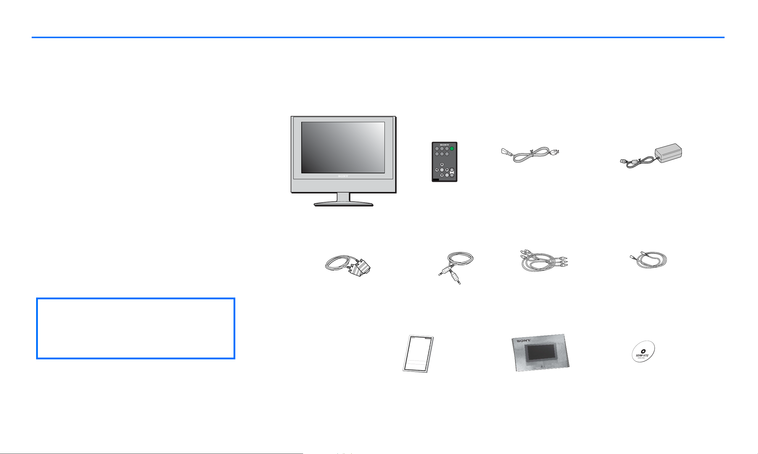
Before using your display, check that the following items are included in your carton:
■ LCD display
■ Remote card
■ AC Power cord
■ AC Adapter (AC-DP001)
■ HD15/D-sub video signal cable (analog RGB)
■ Audio cord (stereo miniplug)
■ Composite video extension cable
■ S-Video extension cable
■ Warranty card
■ Quick Setup Guide
■ This instruction manual on CD-ROM
✍
zThis display can be wall mounted
Display
HD15/D-sub video signal cable
Picture
Wide
Mute
Power
Mode
Mode
PC
Y/Pb/Pr
Video
OK
Volume
Menu
DISPLAY
RM-V72W
Remote card
Audio cord
AC Power Cord
Composite video extension cable
AC Adapter
S-Video Extension Cable
with VESA Standard Wall Mount. For
instruction and mounting bracket
please refer to your local retailer.
- 8 -
4-062-412-
13
C
o
m
p
u
t
e
r
D
i
s
p
l
a
y
P
r
o
d
u
c
t
s
LIM
IT
E
D
W
A
R
R
A
N
TY
S
o
n
y
E
l
e
c
t
r
o
n
i
c
s
I
n
c
.
a
n
d
S
o
n
y
o
f
C
a
n
a
d
a
L
t
m
d
.
a
(
t
“
e
S
r
O
i
a
N
l
o
Y
r
”
w
)
w
o
r
a
k
r
m
r
a
a
n
n
t
s
s
h
t
i
h
p
i
s
a
P
s
r
f
o
o
d
l
l
u
o
c
w
t
s
a
:
g
a
i
n
s
t
d
e
f
e
c
t
s
i
1
.
L
A
B
t
o
b
e
d
e
f
e
p
a
y
t
h
e
l
a
p
a
y
f
o
r
a
l
l
2
.
P
AR
T
S
f
o
r
d
e
f
e
c
t
i
v
e
p
a
r
t
s
c
o
s
t
.
T
o
o
b
t
a
i
n
w
a
r
e
i
t
h
e
r
i
t
s
o
r
i
g
i
n
S
o
n
y
S
e
r
v
i
c
e
f
T
h
i
s
w
a
r
r
a
n
t
y
d
o
p
r
o
b
l
e
m
s
.
T
h
i
s
w
a
r
r
a
n
t
y
d
o
e
a
n
y
o
n
e
o
t
h
e
r
t
h
a
n
n
u
m
b
e
r
h
a
s
b
e
e
n
a
d
u
e
t
o
a
c
t
s
o
f
G
o
d
,
a
n
y
p
a
r
t
o
f
t
h
e
P
r
o
m
a
i
n
t
e
n
a
n
c
e
,
c
o
n
n
e
A
S
I
S
o
r
W
I
T
H
A
L
L
F
T
h
i
s
w
a
r
r
a
n
t
y
i
s
v
a
l
i
d
p
u
r
c
h
a
s
e
.
P
r
o
o
f
o
f
p
u
r
c
h
a
s
e
i
n
t
h
w
i
t
h
i
n
t
h
e
W
a
r
r
a
n
t
y
p
e
r
T
h
i
s
w
a
r
r
a
n
t
y
i
s
i
n
v
a
l
i
d
i
P
r
o
d
u
c
t
.
R
E
P
A
I
R
O
R
R
E
P
L
A
C
E
M
E
N
T
O
F
T
H
E
C
O
N
S
U
M
E
R
.
S
O
N
D
A
M
A
G
E
S
F
O
R
B
R
E
A
C
H
O
F
T
O
T
H
E
E
X
T
E
N
T
P
R
O
H
I
M
E
R
C
H
A
N
T
A
B
I
L
I
T
Y
O
R
F
I
T
N
D
U
R
A
T
I
O
N
T
O
T
H
E
D
U
R
A
T
I
O
S
o
m
e
s
t
a
t
e
s
a
n
d
p
r
o
v
i
n
c
e
s
d
o
d
a
m
a
g
e
s
,
o
r
a
l
l
o
w
l
i
m
i
t
a
t
i
o
n
s
e
x
c
l
u
s
i
o
n
s
m
a
y
n
o
t
a
p
p
l
y
t
o
y
o
o
t
h
e
r
r
i
g
h
t
s
w
h
i
c
h
v
a
r
y
f
r
o
m
s
t
a
FOR FREQ
UENTL
Y CALL
ED TELEPHONE NUM
n
O
R
:
F
o
r
a
p
e
r
i
o
d
o
f
t
h
r
e
e
(
3
)
y
e
a
r
s
f
r
o
m
t
h
e
d
a
t
c
e
t
i
v
o
e
f
,
p
S
u
o
r
c
n
h
y
a
w
s
e
i
l
,
l
i
r
f
e
t
h
p
i
a
s
i
r
P
o
r
o
r
d
r
u
e
p
c
t
l
a
i
s
c
e
d
e
t
h
t
e
e
r
m
P
r
i
o
n
d
e
u
d
c
t
b
w
o
i
r
t
h
c
h
a
a
n
r
g
e
e
w
s
t
o
o
r
a
r
e
n
b
y
u
S
i
l
o
t
n
u
y
n
i
a
t
,
u
a
t
h
t
o
n
r
o
i
z
c
e
h
d
a
s
r
e
g
r
e
v
,
i
o
c
e
r
f
a
l
c
a
i
b
l
i
o
t
y
r
.
A
c
h
f
t
a
e
r
r
g
t
e
h
s
e
.
W
a
r
r
a
n
t
y
P
e
r
i
o
d
,
y
o
u
m
u
s
t
:
I
n
a
d
d
i
t
i
o
n
,
S
o
n
y
w
i
l
l
s
u
p
p
l
y
,
a
t
n
o
c
h
a
r
g
e
,
n
e
p
w
a
r
o
t
s
r
f
r
o
e
r
b
u
a
i
l
p
t
e
r
r
e
i
p
o
l
d
a
c
o
e
f
m
t
h
e
r
n
e
t
e
s
(
i
3
n
)
e
y
x
e
c
a
h
r
a
s
n
.
g
A
e
f
t
e
r
t
h
e
w
a
r
r
a
n
t
y
p
e
r
i
o
d
,
y
o
u
m
u
s
t
p
a
y
f
o
r
a
l
l
r
a
n
t
y
s
e
r
v
i
c
e
,
y
o
u
m
u
s
t
t
a
k
e
t
h
e
P
r
o
d
u
c
t
,
o
r
d
a
e
l
p
l
i
v
a
e
c
k
r
a
t
g
h
i
e
n
g
P
r
o
o
r
d
p
u
a
c
c
t
k
f
a
r
g
e
i
i
g
n
h
g
t
a
p
f
f
r
o
e
r
p
d
a
i
n
i
d
g
,
a
i
n
n
e
q
u
a
l
a
d
c
e
i
g
l
i
t
r
y
e
.
e
o
f
p
r
o
t
e
c
t
i
o
n
,
t
o
a
n
y
a
u
t
h
o
r
i
z
e
d
e
s
n
o
t
c
o
v
e
r
c
u
s
t
o
m
e
r
i
n
s
t
r
u
c
t
i
o
n
,
i
n
s
t
a
l
l
a
t
i
o
n
,
s
e
t
u
p
a
d
j
u
s
t
m
e
n
t
s
o
r
s
i
g
n
a
l
r
e
c
e
p
t
i
o
n
s
n
o
t
c
o
v
e
r
a
n
y
u
n
i
t
s
w
h
i
c
h
h
a
v
e
b
e
e
n
p
r
e
v
i
o
u
a
s
l
s
y
e
a
r
v
l
t
i
e
c
r
e
e
f
d
a
,
c
r
i
e
l
i
p
t
y
a
i
a
r
u
e
t
d
h
o
o
r
r
i
s
z
e
e
r
d
v
b
i
c
y
e
S
d
o
b
n
y
y
,
o
r
a
u
n
i
t
o
l
n
t
e
w
r
e
h
d
i
c
o
h
r
t
r
h
e
e
m
f
a
o
c
v
t
e
o
d
r
y
.
-
T
a
h
p
i
p
s
l
w
i
e
a
d
r
s
r
a
e
n
r
i
t
a
y
l
d
o
e
s
n
o
t
c
o
a
v
c
e
c
r
i
d
c
e
o
n
s
t
m
,
m
e
t
i
i
s
c
u
d
s
a
e
m
,
a
a
b
g
u
e
s
o
e
,
r
n
d
e
a
g
m
l
i
a
g
g
e
e
n
c
e
,
c
o
m
m
e
r
d
c
u
i
a
c
l
t
.
u
s
T
e
h
,
i
s
o
r
w
m
a
o
r
r
d
a
i
n
f
i
t
c
y
a
t
d
i
o
o
n
e
s
o
f
n
,
o
o
t
r
t
c
o
o
v
e
r
d
a
m
a
g
e
c
t
i
d
o
u
n
e
t
o
t
o
i
m
i
m
p
r
p
o
r
p
o
e
p
r
e
v
r
o
o
l
t
p
a
e
g
r
e
a
s
t
i
u
o
p
n
p
o
l
y
r
.
T
h
i
s
w
a
r
r
a
n
A
t
y
U
d
L
T
o
S
e
s
.
n
o
t
c
o
v
e
r
p
r
o
d
u
c
t
s
s
o
l
d
o
n
l
y
i
n
t
h
e
U
n
i
t
e
d
S
t
a
t
e
s
a
n
d
C
a
n
a
d
a
a
n
d
o
n
l
y
i
n
t
h
e
r
e
s
p
e
c
t
i
v
e
c
o
u
n
t
r
y
o
f
e
f
o
r
m
o
f
a
b
i
l
l
o
f
s
a
l
e
o
r
r
e
c
e
i
p
t
e
d
i
n
v
o
i
c
e
,
w
h
i
i
o
c
h
d
,
i
s
m
e
u
v
s
i
t
d
b
e
n
e
c
p
e
r
e
t
h
s
e
a
n
t
t
t
e
h
d
e
t
u
o
n
o
i
t
b
i
s
t
a
i
n
w
a
r
r
a
n
t
y
s
e
r
v
i
c
e
.
f
t
h
e
f
a
c
t
o
r
y
a
p
p
l
i
e
d
s
e
r
i
a
l
n
u
m
b
e
r
h
a
s
b
e
e
n
a
l
t
e
r
e
d
o
r
r
e
m
o
v
e
d
f
r
o
m
t
h
e
A
S
P
R
O
V
I
D
E
D
U
N
D
E
R
T
H
I
S
W
A
R
R
A
N
T
Y
I
S
T
Y
H
S
E
H
E
A
X
L
C
L
L
N
U
O
S
T
I
V
B
E
E
R
L
E
I
M
A
B
E
L
D
E
Y
F
O
R
A
N
Y
I
N
C
I
D
E
N
T
A
L
A
N
O
Y
R
E
C
X
O
P
N
R
S
E
E
S
Q
S
U
O
E
R
N
I
T
M
I
A
P
L
L
I
E
D
W
A
R
R
A
N
T
Y
O
N
T
B
H
I
T
I
S
E
D
P
R
O
B
D
Y
U
A
C
P
T
.
P
E
L
X
I
C
C
E
A
P
B
T
L
E
L
A
W,
A
N
Y
I
M
P
L
E
I
S
E
S
D
F
O
W
R
A
A
R
P
R
A
A
RT
N
I
T
C
Y
U
L
O
A
F
R
P
U
R
P
O
S
E
O
N
T
H
I
S
P
N
R
O
O
D
F
U
T
C
H
T
I
S
I
S
W
L
A
I
M
R
R
I
T
A
E
N
D
T
I
N
Y
.
n
o
t
a
l
l
o
w
t
h
e
e
x
c
l
u
s
i
o
n
o
r
l
i
m
i
t
a
t
i
o
n
o
f
i
n
c
i
d
o
e
n
n
t
h
a
o
l
o
w
r
l
c
o
o
n
n
g
s
e
a
q
n
u
i
e
m
n
p
t
i
l
a
i
e
l
d
w
a
r
r
a
n
t
y
l
a
s
t
s
,
s
o
t
h
e
u
.
a
T
b
h
o
i
v
s
e
w
l
i
a
m
r
r
i
a
t
a
n
t
t
i
y
o
n
g
s
i
v
o
e
r
s
y
o
u
s
p
e
c
i
f
i
c
l
e
g
a
l
r
i
g
h
t
t
s
e
,
a
t
o
n
d
s
t
y
a
o
t
e
u
o
m
r
a
p
y
r
o
h
v
a
i
n
v
e
c
e
t
o
p
r
o
v
i
n
c
e
.
BERS, PLEASE SEE REVERSE SIDE.
P
r
i
n
t
e
d
i
n
U
S
A
Warranty Card
(T1)
P
CD
Quick Setup Guide
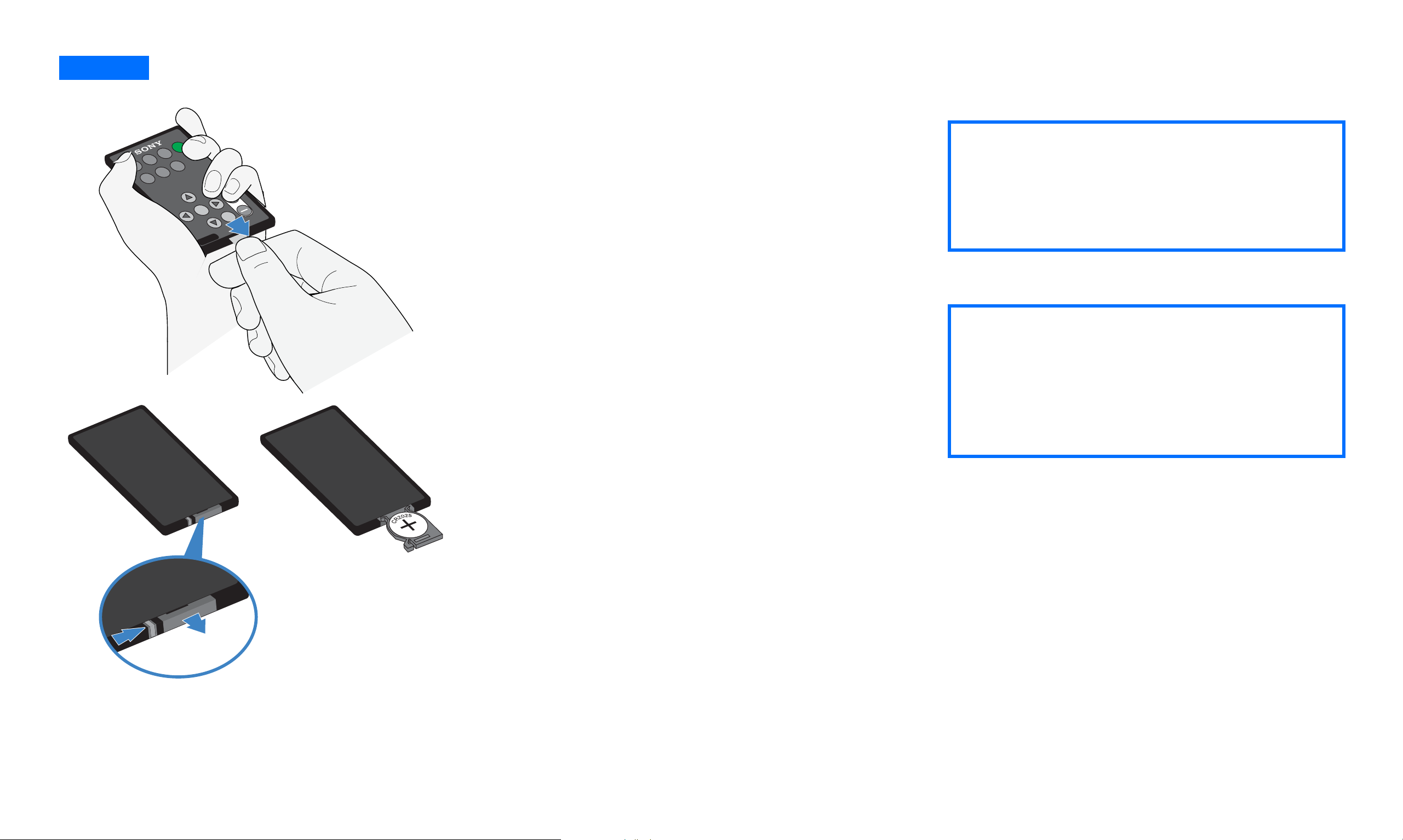
Setup 1
Activating and replacing a battery for remote card
Activating the remote card
Power
Mute
Picture
Wide
Mode
Mode
Y/Pb/Pr
Video
PC
To activate the battery for the remote card,
remove the plastic slip by pulling the tab.
✍
zHandle the remote card with care. Do
not try to bend it, drop it or get it wet. Avoid
OK
DISPLAY
Menu
Volume
RM-V72W
placing it near a heater, in direct sunlight, or
R
where humidity is high.
Replacing the remote card battery
1 To replace the worn battery with a new
one, remove the battery compartment
from the remote card by pressing the
Caution: Keep the batteries away from the
lock latch to the right, then pull out the
reach of young children. Batteries may pose
compartment.
a potential health hazard if put in their
2 Be sure that the positive terminal (+) of
the CR2025 lithium battery is facing
mouth (i.e., they may swallow it or choke on
it).
upward.
3 Close the battery compartment to with a
gentle push until you hear the click.
1
2
The worn battery should be disposed
properly. Check with your local regulations.
- 9 -
Setup 2
Turn off the display and computer before connecting. Do not touch the pins of the video signal cable connector as this might bend the pins.
Connecting your display to your computer
1 Remove the back panel by holding top
with one hand as in the illustration then
snap out the buttons located at each
corner.
1
2
2 Remove the cable cover by lightly pulling
top concave portion.
■ Connecting to an IBM PC/AT or compatible
computer
Using the HD15/D-sub cable (supplied),
connect the computer to the display’s HD15
input connector.
Connecting a MacintoshConnecting to an IBM PC/AT
Be sure to check the alignment of the HD15/
D-sub cable. Do not force the connector in
the wrong way or the pins might bend.
- 10 -
■ Connecting a Macintosh
When connecting a Macintosh computer,
use an adapter (not supplied) if necessary.
Connect the adapter to the computer before
connecting the video signal cable.

Setup 3
Connecting the audio cord
Connect the supplied audio cord to the display’s
PC audio input jack. The audio cord connector
and the audio input jack are color coded. Match
like colors to connect.
Using the display’s speakers or headphones, you
can listen to sound from your computer or other
audio equipment connected to the display’s
audio input jacks.
For more information, see “Controlling the
volume” on page 33.
- 11 -
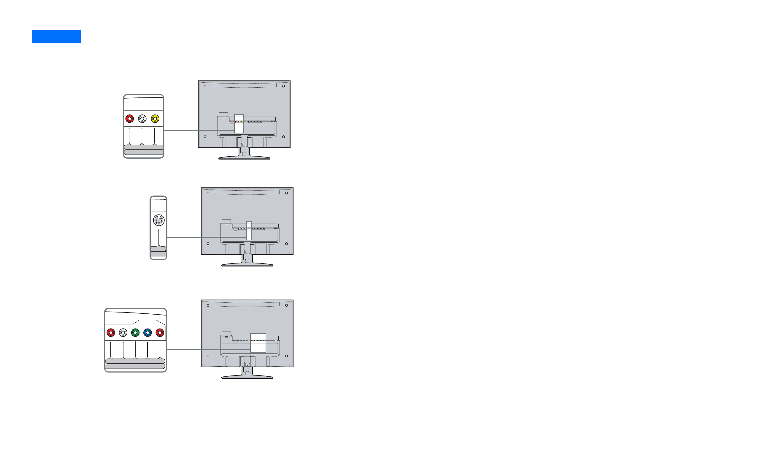
Setup 4
PBR L
P
R
Y
VIDEOR L
VIDE
S VIDEO
Connecting video cables
You can connect composite video cables, S-Video cable, and also Y/Pb/Pr Component Video cables for your video needs.
■ Connecting with composite video cables
Composite video sends combined signal of color shade
(chrominance) and brightness (luminance) through a
single cable. For this connection use the traditional A/V
cable. (Combined audio L/R and video cable)
■ Connecting with S-Video cables
If your equipment has an S-Video output, use this
connection for better picture quality than the
composite video connection. You will need to connect
audio cables (audio L/R) for the sound (S-Video carries
only the video signal).
■ Connecting with Y/Pb/Pr Component Video cables
If your equipment has a Y/Pb/Pr Component Video
output, use this connection for the highest quality
color picture. Y/Pb/Pr Component Video sends signals
of two color shades (chrominance) and brightness
(luminance) separately. Y/Pb/Pr Component Video
cables are usually marked with Y, Pb and Pr. In addition
to the Y/Pb/Pr Component Video, you will also need to
connect an audio L/R cable for sound.
- 12 -
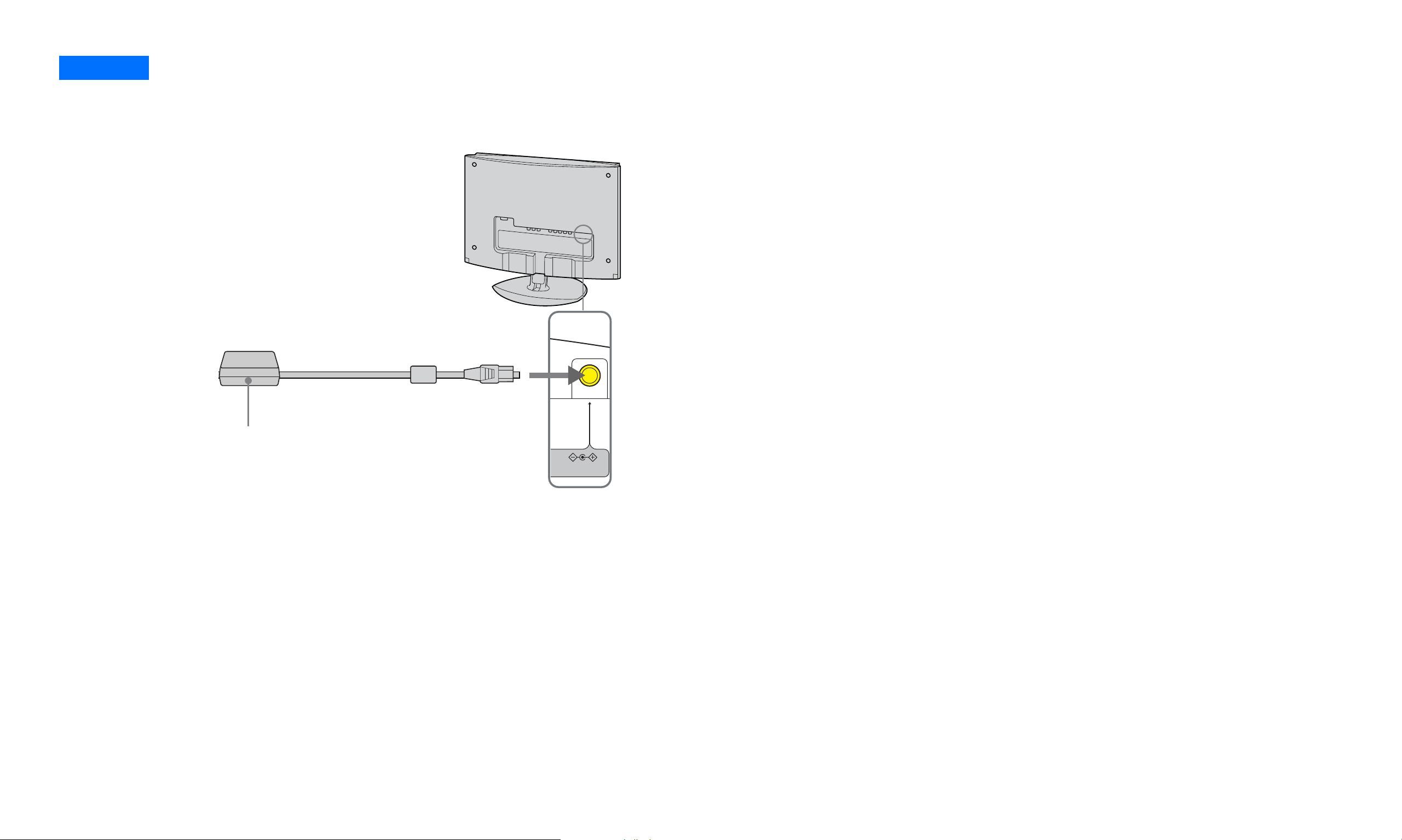
Setup 5
Connecting the AC adapter
Connect the AC adapter (supplied) to the display.
AC adapter
(supplied)
DC IN 16.5V
- 13 -
 Loading...