

Dismantling Information forUse
by ProfessionalRecyclers
ORIGINAL MANUAL ISSUE DATE: 5/2022
Model:
SDM-U27M90
LCD Digital Color Monitor
Conditions of Use:
(1) Please use this information only for the purpose of performing repair and recycling Sony products.
Using this information for any purpose other than the purpose described foregoing is forbidden.
(2) Do not copy, replicate, reproduce, alter, translate, transmit, sell, lease, or distribute this information
in whole or in part without the prior written permission of the author.
Revision of Information:
This information may be changed or updated at any time without any prior notice. Please confirm that
this information is up-to-date before using it.
9-888-878-41
Sony Corporation
© 2022. 5
MODEL LIST/REVISION HISTORY
MODEL COLOR COMMANDER DEST.
SDM-U27M90 White CEI
SDM-U27M90
2

SAFETY NOTE
1-1. Warnings and Caution
1) CAUTION :These servicing instructions are for use by qualified
service personnel only.
2) To reduce the risk of electric shock, do not perform any servicing other
than that contained in the operating instructions unless you are qualified to
do so.
3) WARNING!! : An isolation transformer should be used during any
service to avoid possible shock hazard, because of live chassis. The
chassis of this receiver is directly connected to the ac power line.
The replaceable fuse could be in the neutral of the mains supply. When
replacing the fuse, the mains shall be disconnected for de-energize the
phase conductors.
(*Except AC ADAPTOR, Because it does not carry out replacing an
internal fuse.)
4) CARRYING THE TV : Be sure to follow these guidelines to protect
your property and avoid causing serious injury :
• Carry the TV with an adequate number of people; larger size TVs
require two or more people.
•Correct hand placement while carrying the TV is very important
for safety and to avoid damages.
5) SAFETY-RELATED COMPONENT WARNING!! : Components
identified by shading and ! mark on the exploded views, and in the parts
list are critical for safe operation. Replace these components with Sony
parts whose part numbers appear as shown in this manual or in
supplements published by Sony. Circuit adjustments that are critical for
safe operation are identified in this manual. Follow these procedures
whenever critical components are replaced or improper operation is
suspected.
6) IMPORTANT REMINDER FOR TV MAINBOARD REPLACEMENT :
It is mandatory for service centers to confirm the TV‘s system information
after each repair carried out with Mainboard replacement.
Whenever a TV Main board is replaced, the correct TV Model and Serial
number must be reinserted into memory.
This is a MANDATORY procedure that each service center must apply.
Please refer to the chapter of ADJUSTMENT in this service manual to find
out how to set the model number and serial number in service mode.
1-2. Caution Handling of LCD Panel
When repairing the LCD Panel, make sure you are grounded with a wrist
band.
When repairing the LCD Panel on the wall, the panel must be secured
using the 4 mounting holes on the rear cover.
1) Do not press the panel or frame edge to avoid the risk of electric
shock.
2) Do not scratch or press on the panel with any sharp objects.
3) Do not leave the module in high temperature or in areas of high humidity
for an extended period of time.
4) Do not expose the LCD panel to direct sunlight.
5) Avoid contact with water. It may cause short circuit within the module.
6) Disconnect the AC power when replacing the backlight (CCFL) or
inverter circuit. (High voltage occurs at the inverter circuit at 650Vrms)
7) Always clean the LCD panel with a soft cloth material.
8) Use care when handling the wires or connectors of the inverter circuit.
Damaging the wires may cause a short circuit.
9) Protect the panel from ESD to avoid damaging the electronic circuit
(C-MOS).
SDM-U27M90
3
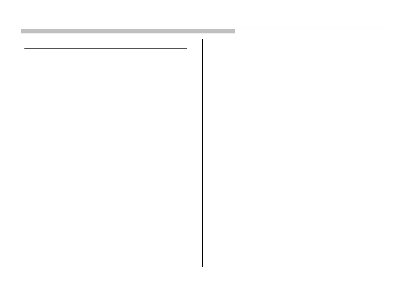
10) During the repair, DO NOT leave the Power On or Burn-in period for
more than 1 hour while the TV is face down on a cloth. Refer Figure 1.
Figure 1.
1-3. Caution_for_Board_handling
Symptom : The following problems will occur due to handling of the IC
mounted on the board.
Solder crack due to substrate handling (stress)
・
・
IC breakdown due to static electricity (ESD)
When repairing the TV at the customer‘s home or service station or
Repair of defect board, please pay attention to the handling of the board.
SAFETY NOTE
1-4. Caution About the Lithium Battery
1) Danger of explosion if battery is incorrectly replaced. Replace only
with the same or equivalent type.
2) Outer case broken battery should not contact to water.
1-5. Safety Check-Out
After correcting the original service problem, perform the following
safety checks before releasing the set to the customer:-
1) Check the area of your repair for unsoldered or poorly soldered
connections. Check the entire board surface for solder splashes and
bridges.
2) Check the inter board wiring to ensure that no wires are pinched or
contact high-wattage resistors.
3) Check all control knobs, shields, covers, ground straps and mounting
hardware have been replaced. Be absolutely certain you have replaced
all the insulators.
4) Look for unauthorized replacement parts, particularly transistors that
were installed during a previous repair. Point them out to the customer
and recommend their replacement.
5) Look for parts which, though functioning show obvious signs of
deterioration. Point them out to the customer and recommend their
replacement.
6) Check the line cords for cracks and abrasion. Recommend the
replacement of any such line cord to the customer.
7) Check the antenna terminals, metal trim, metalized knobs, screws and
all other exposed metal parts for AC leakage. Check leakage test as
described next.
8) For safety reasons, repairing the Power board and/or Inverter board is
prohibited.
SDM-U27M90
4
SAFETY NOTE
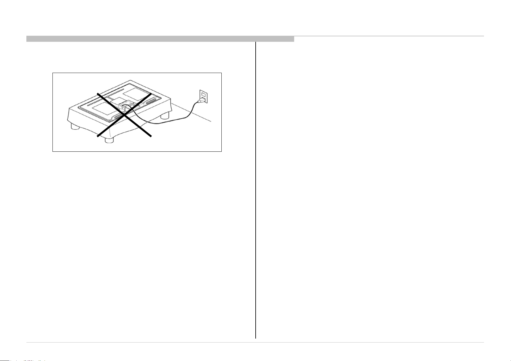
1-6. Leakage Test
(To protect electric shock when customer touch the terminal.)
Leakage current can be measured by V: Voltmeter or oscilloscope
(r.m.s. or peak reading)
Stabilized power supply instrument and isolated voltage transformer:
Use too much current capacity and isolated voltage transformer does
not need to use stabilized power supply equipment.
Specification of RMS volt meter: Input resistance > 1 Mohm, Input
capacitance < 200 pF, Frequency range: 15 Hz – 1MHz . Refer
Figure 2. Isolated type volt -meter (FLUKE 8921A etc *1)
*1 Not use FLUKE 8920A that connected to protective earth by diode
# Leakage current of measurement instrument is less than 10μArms
when under test equipment AC plug is opened
# Set up the following condition and turn on the set. Applied voltage:
Nominal input voltage (Description on Nameplate)
# Measure the leakage current between one phase conductor and
neutral for terminal A and terminal B.
Read rms value, and then calculate to peak value PEAK VALUE =√2
RMS VALUE
Comply with the following requirement
Class II equipment (2-pin plug): for each terminal, the worst value
of measurementmust not exceed AC 350uA peak).
Note: including AC adaptor, AC adaptor/DC operated unit
combination
Figure 2 – Measuring network
for Leakage Current
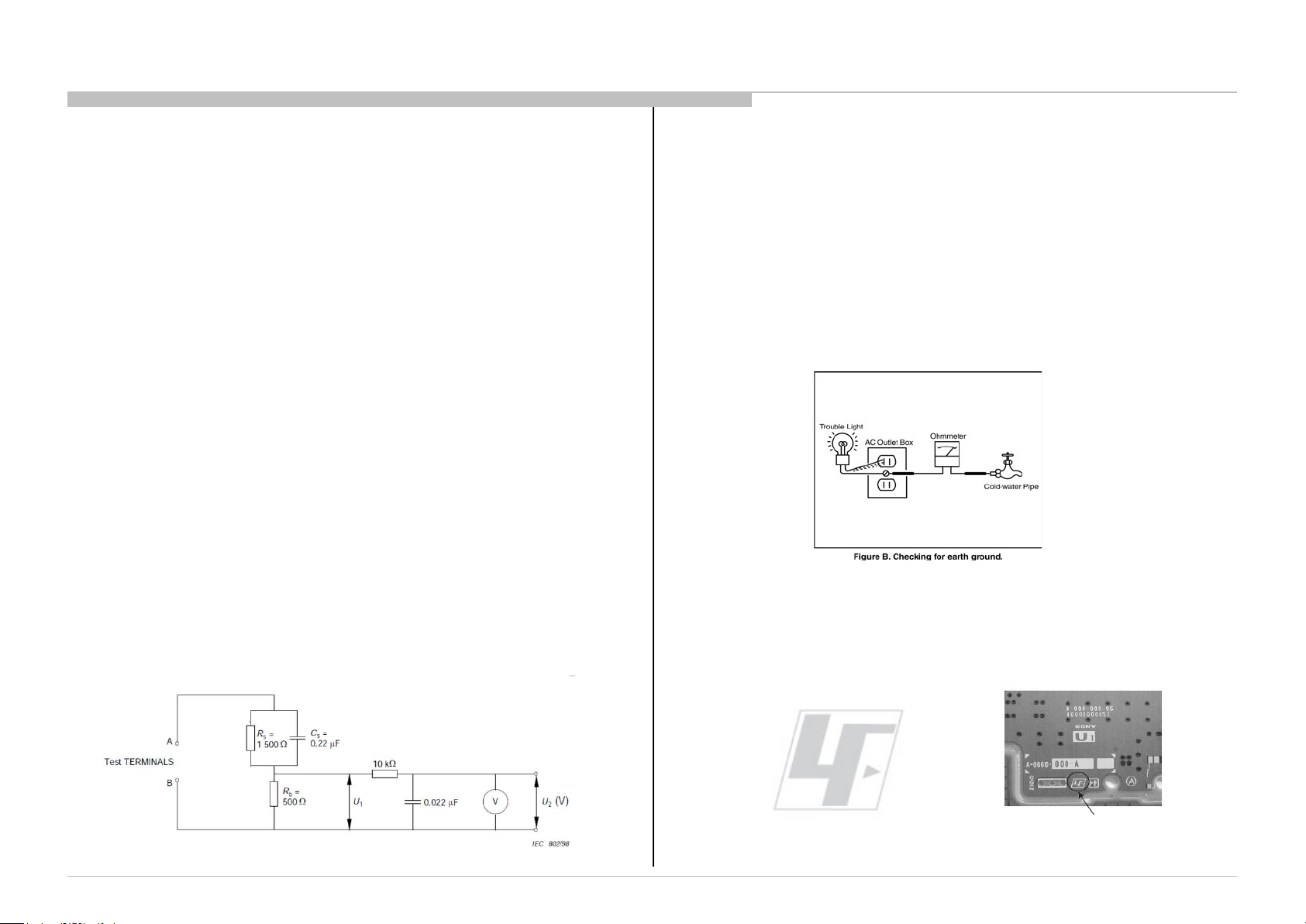
1-7. How to Find a Good Earth Ground
1) A cold-water pipe is a guaranteed earth ground; the cover-plate
retaining screw on most AC outlet boxes is also at earth ground.
2) If the retaining screw is to be used as your earth ground, verify that it is
at ground by measuring the resistance between it and a cold-water pipe
with an ohmmeter.The reading should be zero ohms.
3) If a cold-water pipe is not accessible, connect a 60- to 100-watt troublelight (not a neon lamp) between the hot side of the receptacle and the
retaining screw. Try both slots, if necessary, to locate the hot side on the
line; the lamp should light at normal brilliance if the screw is at ground
potential (see Figure 3).
Figure 3. Checking for earth
ground.
1-8. Lead Free Information
The circuit boards used in these models have been processed using
Lead Free Solder. The boards are identified by the LF logo located
close to the board designation.
SDM-U27M90
Figure 4: LF Logo
Figure 5: LF logo on circuit board
5
The servicing of these boards requires special precautions. It is
strongly recommended to use Lead Free Solder material in order to
guarantee optimal quality of new solder joints.
SAFETY NOTE
SDM-U27M90
6
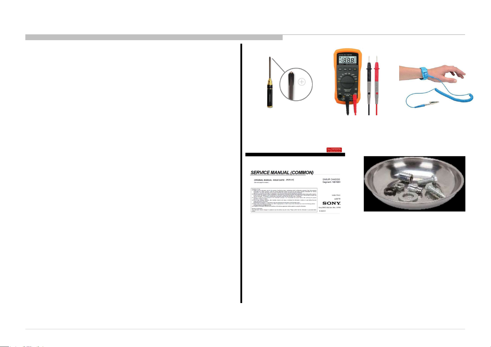
TOOLS & EQUIPMENTS
1 LIST OF ITEMS TO BRING
(1) Screwdriver (e.g. #2 Phillips Screwdriver)
(2) Multimeter
(3) ESD WristStraps
(4) Service Manual (Unique)
(for remove & replace details)
2 OPTIONAL EQUIPMENT
(5) Screwdriver (e.g. #1 Phillips Screwdriver)
(6) Parts Tray for loose screws and small items
3 PREPARATION BEFORE REPAIRS
Before you begin, unplug the AC power plug from
the desk or wall outlet . Then simply place the
monitor faced-down on top of a thick blanket, on a
large/flat surface.
(1) (5) (2) (3)
(4) (6)
SDM-U27M90
7

SERVICE POSITION
1. Press VESA QR POM to
remove stand.
4. Remove the fix screws on Main Board &
Driver Board as picture shows (9 screws).
2. Remove all screws on the Rear Cover (4 screws).
3. Remove all screws on the Main Bracket
(5 screws).
5. Remove all screws on the front
bezel (13 screws).
SDM-U27M90
REF. No. PART No. DESCRIPTION REMARKS
5-042-480-01 SCREW M4x11 4 pcs
5-042-479-01 SCREW M3x3.7 5 pcs
5-042-497-01 SCREW M3*7.5 9 pcs
5-042-496-01 SCREW M3x5 13 pcs
8

1. DISASSEMBLY AND PARTS LIST
• Items with no part number and no description are not stocked because they are seldom required for routine service.
• The construction parts of an assembled part are indicated with a collation number in the remark column.
• Items marked " * " are not stocked since they are seldom required for routine service. Some delay should be anticipated when ordering these items.
1-1. How to disassemble stand
Rear Cover cannot disassemble standing condition.
REF. No. PART No. DESCRIPTION REMARKS
1 5-042-492-01 21_SO_U27_STAND_RISER
1
2 5-042-493-01 21_SO_U27_STAND_V-LEG
SDM-U27M90
Press VESA QR POM on
button of the rear cover.
2
Hold the stand riser and rise it to
remove the stand.
9

1-2. How to disassemble rear cover
1. Remove all screws on the Rear Cover (4 screws).
DISASSEMBLY AND PARTS LIST
REF. No. PART No. DESCRIPTION REMARKS
1 5-042-491-01 ASSY_21_SO-U27_REAR_COVER Rear cover
2 5-042-489-01 ASSY_21_SO-U27_BRACKET Main bracket
5-042-480-01 Screw M4 11 4 pcs
SDM-U27M90
1
2
10

1-2. How to disassemble rear cover
2. Open Rear Cover in order as below.
DISASSEMBLY AND PARTS LIST
REF. No. PART No. DESCRIPTION REMARKS
1 5-044-804-01 AL FOIL EMI_AL_TAPE_W90XL120 Rem ove 1 pc
(3)
(3)
(3)
(1)
(2)
(2)(2)(2)
(4)(4) (4) (4)
(3)
(3)
(3)
Rear Cover cannot be disassembled
in the standing condition.
Be careful when removing the rear cover
because Key BD's FFC and illumination
cable are connected.
Do not pinch the cables when assembling
the rear cover.
SDM-U27M90
1
Remove AL tape.
11

1-3. How to disassemble main bracket
1-3-1. Procedure of removing tapes and screws
1. Remove the tapes on the FFC cables.
2. Remove the screws M3x3.7 (5 pcs).
DISASSEMBLY AND PARTS LIST
REF. No. PART No. DESCRIPTION REMARKS
1 5-042-481-01 EMI_AL_TAPE_W50XL80_IN_PIECE 3 pcs
2 5-042-482-01 EMI_AL_TAPE_W80XL100_IN_PIECE 1 pc
3 5-043-762-01 ACETATE_TAPE_30X40MM 1 pc
5-042-479-01 Screw M3*3.7L 5 pcs
1
SDM-U27M90
2
1
3
Two tapes are attached.
The aluminum tape (1) is at the top
and the black tape (3) is at the bottom.
3
12

1-3. How to disassemble main bracket
1-3-2. Procedure of removing FFC cable
1
DISASSEMBLY AND PARTS LIST
REF. No. PART No. DESCRIPTION REMARKS
1 1-015-579-11 FFC (dirver BD/BL) LB1 LB FFC
2 1-015-580-11 FFC (dirver BD/BL) LB2 LB FFC
3 1-015-578-11 LVDS FFC (MB -Panel) LVDS cable
Open the connector cover.
2
SDM-U27M90
3
Remove the LVDS FFC.
13

1-4. How to disassemble Main board and Driver board
1-4-1. Disassembly of Main board and Driver board on main bracket
REF. No. PART No. DESCRIPTION REMARKS
1
7
6
DISASSEMBLY AND PARTS LIST
1 1-015-579-11 FFC (dirver BD/BL) LB1 LB FFC
2 1-015-580-11 FFC (dirver BD/BL) LB2 LB FFC
3 1-015-573-11 MOUNTED PWB (Driver Board) Driver board
4 1-015-594-11 CONN. ASSY (MB- DB)
5 1-015-572-11 MOUNTED PWB A (MB) Main board
6 1-015-578-11 LVDS FFC (MB -Panel) ePD
7 1-015-581-11 FFC (IF/dirver BD) control
8 5-042-486-01 T_PAD_14_9_T2 Thermal pad 4 pcs
9 5-042-485-01 T-PAD _30*30*T2_K=5 Thermal pad 2 pcs
5-042-497-01 SCRW M3*7.5 9 pcs
Cable for Main BD
and Driver BD
FFC for Main BD and
Driver BD
Printed Circuit
Board, incl.
capacitors
Printed Circuit
Board, incl.
capacitors
2
SDM-U27M90
3 4
5
Remove the screws M3x7.5 (9 pcs).
8
9
14

MOUNTED PWB (Driver Board)
1-4. How to disassemble Main board and Driver board
1-4-2. Procedure of removing FFC cable and other cable
1
5
4
Loosen the cable
lock.
DISASSEMBLY AND PARTS LIST
REF. No. PART No. DESCRIPTION REMARKS
1 1-015-580-11 FFC (dirver BD/BL) LB2 LB FFC
2 1-015-579-11 FFC (dirver BD/BL) LB1 LB FFC
3 1-015-581-11 FFC (IF/dirver BD) control
4 1-015-594-11 CONN. ASSY (MB- DB)
5 1-015-578-11 LVDS FFC (MB -Panel) ePD
6 1-015-573-11
7 1-015-572-11 MOUNTED PWB A (MB) Main board
FFC for Main BD
and Driver BD
Cable for Main BD
and Driver BD
Driver board
Remove the LVDS FFC.
Printed Circuit
Board,
incl. capacitors
Printed Circuit
Board,
incl. capacitors
2
Open connector cover.
SDM-U27M90
7
3
Driver board
Main board
6
15

DISASSEMBLY AND PARTS LIST
1-5. How to disassemble front bezel
REF. No. PART No. DESCRIPTION REMARKS
1 5-042-490-01 ASSY_21-SO-U27_BEZEL Bezel
2 A-5049-008-A LCM ASSY with individual packing LCM
5-042-496-01 Screw M3L5 13 pcs
Remove the screws M3x5 (13 pcs).
2
Liquid Crystal Display
SDM-U27M90
1
16

1-6. How to disassemble Key board and Power LED board
1. Remove the screws.
DISASSEMBLY AND PARTS LIST
REF. No. PART No. DESCRIPTION REMARKS
1 1-015-575-11 MOUNTED PWB FK Board (Key) Key board
2 1-015-574-11 MOUNTED PWB (Power LED Board) Power LED board
3 5-042-487-01 21_SO_U27_JOYSTICK Joystick cover
5-042-478-01 Screw M3*3.5 3 pcs
1
2
3
SDM-U27M90
17

1-6. How to disassemble Key board and Power LED board
1-6-1. Key board & LED board for service
DISASSEMBLY AND PARTS LIST
SONY PN Description Qty Remarks
1-015-575-11
MOUNTED PWB FK
BOARD (KEY)
1 KEY MODULE
SONY PN Description Qty Remarks
1-015-574-11
Mode LED Status
ON mode WHITE
Sleeping mode Orange
Off mode NA
MOUNTED PWB
(POWER LED BOARD)
1
LED BD
SDM-U27M90
* FFC is attached to the service parts of Key BOARD and LED BOARD.
18

1-7. How to disassemble illumination LED board
1. Release hook to disassemble illumination LED board.
DISASSEMBLY AND PARTS LIST
REF. No. PART No. DESCRIPTION REMARKS
1 A-5049-009-A MOUNTED PWB (LED_LEFT_RIGHT) Illumination LED
2 5-042-491-01 ASSY_21_SO-U27_REAR_COVER Rear cover
1
2
* A-5049-009-A: Board and harness are assembled.
SDM-U27M90
19

1-8. MISCELLANEOUS
REF. No. PART No. DESCRIPTION REMARKS
1 1-015-585-11 AC CORD -EU FOR CEI (except UK) region Cable
1-015-586-11 AC CORD -UK FOR CEI (UK) region Cable
2 1-015-582-11 ADAPTER FOR ALL region External Power Supply
DISASSEMBLY AND PARTS LIST
SDM-U27M90
20

2-2. CIRCUIT BOARDS LOCATION
DIAGRAMS AND CHASSIS STRUCTURE
Illumination LED board
Illumination LED board
Key board
LED board
Main board
Driver board
SDM-U27M90
21

END
9-888-878-41
SDM-U27M90
Sony Corporation
English
2022EL08-Data
Made in Japan
© 2022.5
22
 Loading...