

Sony SDM-S76D, SDM-V96D, SDM-S76F, SDM-S96F, SDM-S76A Operating Instructions Manual
...
2-695-540-03(1)
TFT LCD Color
Computer Display
Operating Instructions
(GB)
SDM-S76A/SDM-S96A
SDM-S76D/SDM-S96D
SDM-V76D/SDM-V96D
SDM-S76F/SDM-S96F
© 2006 Sony Corporation

Owner’s Record
The model and serial numbers are located at the rear of the unit.
Record these numbers in the spaces provided below. Refer to them
whenever you call upon your dealer regarding this product.
Model No.
Serial No.
WARNING
To reduce the risk of fire or electric shock, do not
expose this apparatus to rain or moisture.
Dangerously high voltages are present inside the
unit. Do not open the cabinet. Refer servicing to
qualified personnel only.
FCC Notice
This equipment has been tested and found to comply with the limits
for a Class B digital device, pursuant to Part 15 of the FCC Rules.
These limits are designed to provide reasonable protection against
harmful interference in a residential installation. This equipment
generates, uses, and can radiate radio frequency energy and, if not
installed and used in accordance with the instructions, may cause
harmful interference to radio communications. However, there is no
guarantee that interference will not occur in a particular installation.
If this equipment does cause harmful interference to radio or
television reception, which can be determined by turning the
equipment off and on, the user is encouraged to try to correct the
interference by one or more of the following measures:
– Reorient or relocate the receiving antenna.
– Increase the separation between the equipment and receiver.
– Connect the equipment into an outlet on a circuit different from
that to which the receiver is connected.
– Consult the dealer or an experienced radio/TV technician for help.
You are cautioned that any changes or modifications not expressly
approved in this manual could void your authority to operate this
equipment.
NOTICE
This notice is applicable for USA/Canada only.
If shipped to USA/Canada, install only a UL LISTED/CSA
LABELLED power supply cord meeting the following
specifications:
SPECIFICATIONS
Plug Type Nema-Plug 5-15p
Cord Type SVT or SJT, minimum 3 × 18 AWG
Length Maximum 15 feet
Rating Minimum 7 A, 125 V
NOTICE
Cette notice s’applique aux Etats-Unis et au Canada
uniquement.
Si cet appareil est exporté aux Etats-Unis ou au Canada, utiliser
le cordon d’alimentation portant la mention UL LISTED/CSA
LABELLED et remplissant les conditions suivantes:
SPECIFICATIONS
Type de fiche Fiche Nema 5-15 broches
Cordon Type SVT ou SJT, minimum 3 × 18 AWG
Longueur Maximum 15 pieds
Tension Minimum 7 A, 125 V
ENERGY STAR Partner, Sony
As an
Corporation has determined that this product
meets the
energy efficiency.
ENERGY STAR guidelines for
IMPORTANTE
Para prevenir cualquier mal funcionamiento y evitar daños, por
favor, lea detalladamente este manual de instrucciones antes
de conectar y operar este equipo.
If you have any questions about this product, you may call;
Sony Customer Information Services Center
1-800-222-7669 or http://www.sony.com/
Declaration of Conformity
Trade Name: SONY
Model: SDM-S76A/SDM-S96A
SDM-S76D/SDM-S96D
SDM-V76D/SDM-V96D
SDM-S76F/SDM-S96F
Responsible Party: Sony Electronics Inc.
Address: 16530 Via Esprillo,
San Diego, CA 92127 U.S.A.
Telephone Number: 858-942-2230
This device complies with part 15 of the FCC rules. Operation is
subject to the following two conditions: (1) This device may not
cause harmful interference, and (2) this device must accept any
interference received, including interference that may cause
undesired operation.
This monitor complies with the
TCO’03 guidelines.
(SDM-S76A/SDM-S96A/SDM-S76D/SDM-S96D/
S D M - S 7 6 F / S D M - S 9 6 F o n l y )
2 (GB)
Table of Contents
• Macintosh is a trademark licensed to
Apple Computer, Inc., registered in the
U.S.A. and other countries.
• Windows
Microsoft Corporation in the United
States and other countries.
• VESA and DDC
Video Electronics Standards
Association.
ENERGY STAR
•
mark.
• Adobe and Acrobat are trademarks of
Adobe Systems Incorporated.
• All other product names mentioned
herein may be the trademarks or
registered trademarks of their respective
companies.
• Furthermore, “™” and “®” are not
mentioned in each case in this manual.
®
is registered trademarks of
™
are trademarks of the
®
is a U.S. registered
Precautions. . . . . . . . . . . . . . . . . . . . . . . . . . . . . . . . . . . . . . . . . . . . 4
Identifying parts and controls . . . . . . . . . . . . . . . . . . . . . . . . . . . . . . 5
Setup . . . . . . . . . . . . . . . . . . . . . . . . . . . . . . . . . . . . . . . . . .6
Step 1: Assemble the stand . . . . . . . . . . . . . . . . . . . . . . . . . . . . . . . 6
Step 2: Connect the display to your computer . . . . . . . . . . . . . . . . . 7
Step 3: Connect the power cord. . . . . . . . . . . . . . . . . . . . . . . . . . . . 7
Step 4: Secure the cords . . . . . . . . . . . . . . . . . . . . . . . . . . . . . . . . . 8
Step 5: Turn on the display and computer . . . . . . . . . . . . . . . . . . . . 8
Adjusting the tilt . . . . . . . . . . . . . . . . . . . . . . . . . . . . . . . . . . . . . . . . 9
Adjusting the height (SDM-S76F/SDM-S96F only). . . . . . . . . . . . . . 9
Selecting the input signal (INPUT button)
(SDM-S76D/SDM-S96D/SDM-V76D/
SDM-V96D/SDM-S76F/SDM-S96F only) . . . . . . . . . . . . . . . . . . . . . 9
Customizing Your Display . . . . . . . . . . . . . . . . . . . . . . .10
Adjusting to the desired brightness. . . . . . . . . . . . . . . . . . . . . . . . . 10
Navigating the menu . . . . . . . . . . . . . . . . . . . . . . . . . . . . . . . . . . . . 10
Adjusting the backlight (BACKLIGHT) . . . . . . . . . . . . . . . . . . . . . . 11
Adjusting the contrast (CONTRAST) . . . . . . . . . . . . . . . . . . . . . . . 12
Adjusting the black level of an image (BRIGHTNESS). . . . . . . . . . 12
Adjusting the picture’s sharpness and centering (SCREEN)
(analog RGB signal only). . . . . . . . . . . . . . . . . . . . . . . . . . . . . . . . 12
Adjusting the color temperature (COLOR) . . . . . . . . . . . . . . . . . . . 14
Changing the gamma setting (GAMMA). . . . . . . . . . . . . . . . . . . . . 14
Adjusting the sharpness (SHARPNESS) . . . . . . . . . . . . . . . . . . . . 14
Changing the menu’s position (MENU POSITION) . . . . . . . . . . . . 15
Changing the input automatically (INPUT SENSING)
(SDM-S76D/SDM-S96D/SDM-V76D/
SDM-V96D/SDM-S76F/SDM-S96F only) . . . . . . . . . . . . . . . . . . . . 15
Selecting the on-screen menu language (LANGUAGE). . . . . . . . . 15
Additional settings. . . . . . . . . . . . . . . . . . . . . . . . . . . . . . . . . . . . . . 15
Technical Features . . . . . . . . . . . . . . . . . . . . . . . . . . . . .16
Power saving function. . . . . . . . . . . . . . . . . . . . . . . . . . . . . . . . . . . 16
Reducing the power consumption (ECO mode) . . . . . . . . . . . . . . . 16
Automatic picture quality adjustment function
(analog RGB signal only) . . . . . . . . . . . . . . . . . . . . . . . . . . . . . . . . 17
http://www.sony.net/
Troubleshooting. . . . . . . . . . . . . . . . . . . . . . . . . . . . . . . .17
On-screen messages . . . . . . . . . . . . . . . . . . . . . . . . . . . . . . . . . . . 17
Trouble symptoms and remedies . . . . . . . . . . . . . . . . . . . . . . . . . . 18
Specifications. . . . . . . . . . . . . . . . . . . . . . . . . . . . . . . . . .20
TCO’03 Eco-document
(SDM-S76A/SDM-S96A/SDM-S76D/
SDM-S96D/SDM-S76F/SDM-S96F only) . . . . . . . . . . . . . . . . . . . . . .i
3 (GB)
Precautions
Warning on power connections
• Use the supplied power cord. If you use a different power cord,
be sure that it is compatible with your local power supply.
For the customers in the U.S.A.
If you do not use the appropriate cord, this display will not
conform to mandatory FCC standards.
For the customers in the UK
If you use the display in the UK, be sure to use the appropriate
UK power cord.
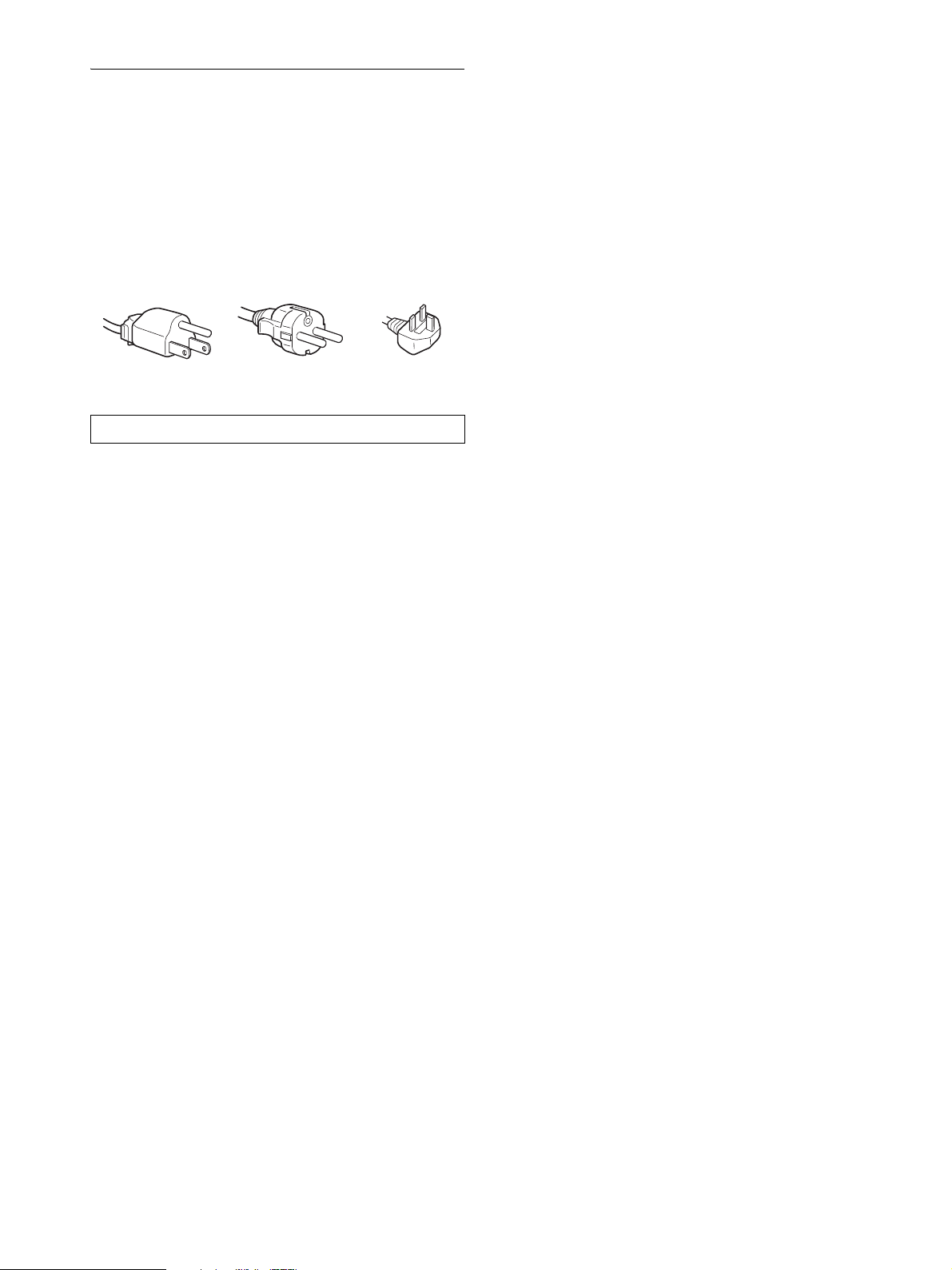
Example of plug types
for 100 to 120 V AC for 200 to 240 V AC for 240 V AC only
The equipment should be installed near an easily accessible outlet.
Installation
Do not install or leave the display:
• In places subject to extreme temperatures, for example near a
radiator, heating vent, or in direct sunlight. Subjecting the
display to extreme temperatures, such as in an automobile
parked in direct sunlight or near a heating vent, could cause
deformations of the casing or malfunctions.
• In places subject to mechanical vibration or shock.
• Near any equipment that generates a strong magnetic field,
such as a TV or various other household appliances.
• In places subject to inordinate amounts of dust, dirt, or sand, for
example near an open window or an outdoor exit. If setting up
temporarily in an outdoor environment, be sure to take
adequate precautions against airborne dust and dirt. Otherwise
irreparable malfunctions could occur.
Place this unit on a flat surface. Do not place it on an uneven
surface like the edge of a desk. If a part of this unit sticks out from
such surface, it may fall or cause damaged and injury.
Handling the LCD screen
• Do not leave the LCD screen facing the sun as it can damage
the LCD screen. Take care when you place the display by a
window.
• Do not push on or scratch the LCD screen. Do not place a heavy
object on the LCD screen. This may cause the screen to lose
uniformity or cause LCD panel malfunctions.
• If the display is used in a cold place, a residual image may
appear on the screen. This is not a malfunction. The screen
returns to normal as the temperature rises to a normal operating
level.
• If a still picture is displayed for a long time, a residual image
may appear for a while. The residual image will eventually
disappear.
• The LCD panel becomes warm during operation. This is not a
malfunction.
Note on the LCD (Liquid Crystal Display)
Please note that the LCD screen is made with highprecision technology. However, black points or bright
points of light (red, blue, or green) may appear
constantly on the LCD screen, and irregular colored
stripes or brightness may appear on the LCD screen.
This is not malfunction.
(Effective dots: more than 99.99%)
Maintenance
• Be sure to unplug the power cord from the power outlet before
cleaning your display.
• Clean the LCD screen with a soft cloth. If you use a glass
cleaning liquid, do not use any type of cleaner containing an
anti-static solution or similar additive as this may scratch the
LCD screen’s coating.
• Clean the cabinet, panel, and controls with a soft cloth lightly
moistened with a mild detergent solution. Do not use any type
of abrasive pad, scouring powder, or solvent, such as alcohol or
benzine.
• Do not rub, touch, or tap the surface of the screen with sharp or
abrasive items such as a ballpoint pen or screwdriver. This type
of contact may result in a scratched picture tube.
• Note that material deterioration or LCD screen coating
degradation may occur if the display is exposed to volatile
solvents such as insecticide, or if prolonged contact is
maintained with rubber or vinyl materials.
Transportation
• Disconnect all cables from the display and grasp the display
firmly with both hands when transporting. If you drop the
display, you may be injured or the display may be damaged.
• When you transport this display for repair or shipment, use the
original carton and packing materials.
Installation on a wall or a mounting arm
If you intend to install the display on a wall or a mounting arm, be
sure to consult qualified personnel.
Disposal of the display
• Do not dispose of this display with general
household waste.
• The fluorescent tube used in this display contains
mercury. Disposal of this display must be carried out
in accordance to the regulations of your local
sanitation authority.
4 (GB)
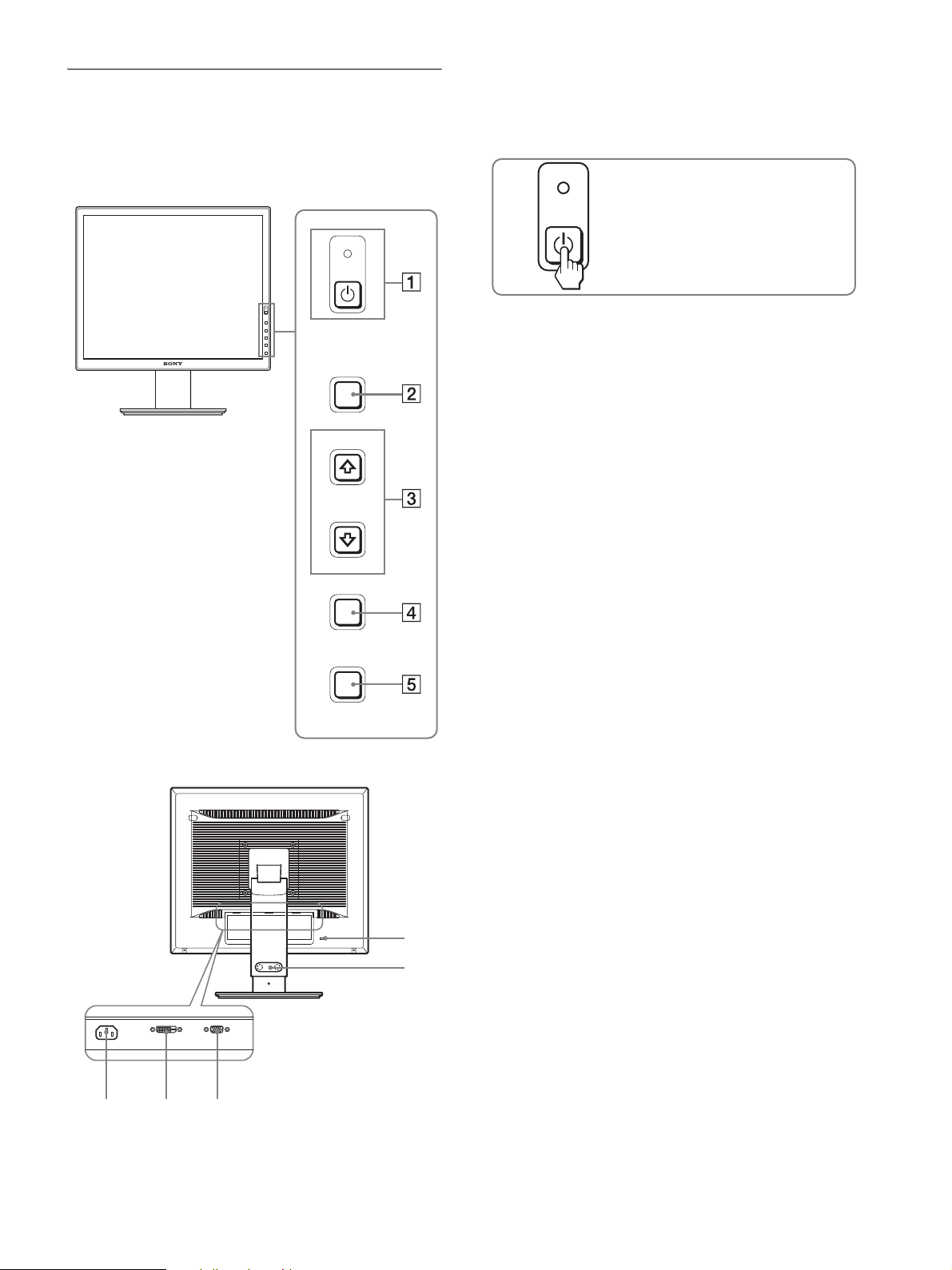
Identifying parts and controls
678
See the pages in parentheses for further details.
The illustration only shows one of all the models that are available
for this display.
Front of the display
MENU
INPUT
OK
1 1 (Power) switch and 1 (power) indicator
(pages 8, 16)
This switch turns the display on. To turn the display off, press
this switch again.
Press to turn the display on or off.
2 MENU button (pages 10, 11)
This button displays or closes the main menu.
You can also switch on the DDC/CI function by keeping this
button pressed for more than 8 seconds.
3 m/M buttons (page 11)
These buttons function as the m/M buttons when selecting
the menu items and making adjustments.
4 OK button (page 11)
This button selects the item or executes the settings in the
menu.
INPUT button (page 9) (SDM-S76D/SDM-S96D/SDMV76D/SDM-V96D/SDM-S76F/SDM-S96F only)
This button switches the video input signal between INPUT1
and INPUT2 when two computers are connected to the
display.
Rear of the display
ECO
0
9
5 ECO button (page 16)
This button is used to reduce the power consumption.
6 AC IN connector (page 7)
Connect the power cord (supplied).
7 DVI-D input connector (digital RGB) for INPUT1
(page 7) (SDM-S76D/SDM-S96D/SDM-V76D/SDMV96D/SDM-S76F/SDM-S96F only)
This connector inputs digital RGB video signals that comply
with DVI Rev.1.0.
8 HD15 input connector (analog RGB) (page 7)
This connector inputs analog RGB video signals (0.7 Vp-p,
positive) and SYNC signals.
9 Cable holder (page 8) (SDM-S76F/SDM-S96F only)
This part secures cables and cords to the display.
0 Security Lock Hole
The security lock hole should be applied with the Kensington
Micro Saver Security System.
Micro Saver Security System is a trademark of Kensington.
5 (GB)
Setup
Before using your display, check that the following items are
included in your carton:
•LCD display
•Power cord
•Stand Base
• HD15-HD15 video signal cable (analog RGB)
• DVI-D video signal cable (digital RGB)
(SDM-S76D/SDM-S96D/SDM-V76D/SDM-V96D/SDMS76F/SDM-S96F only)
• CD-ROM (utility software for Windows/Macintosh, Operating
Instructions, etc.)
• Warranty card
• Quick Setup Guide
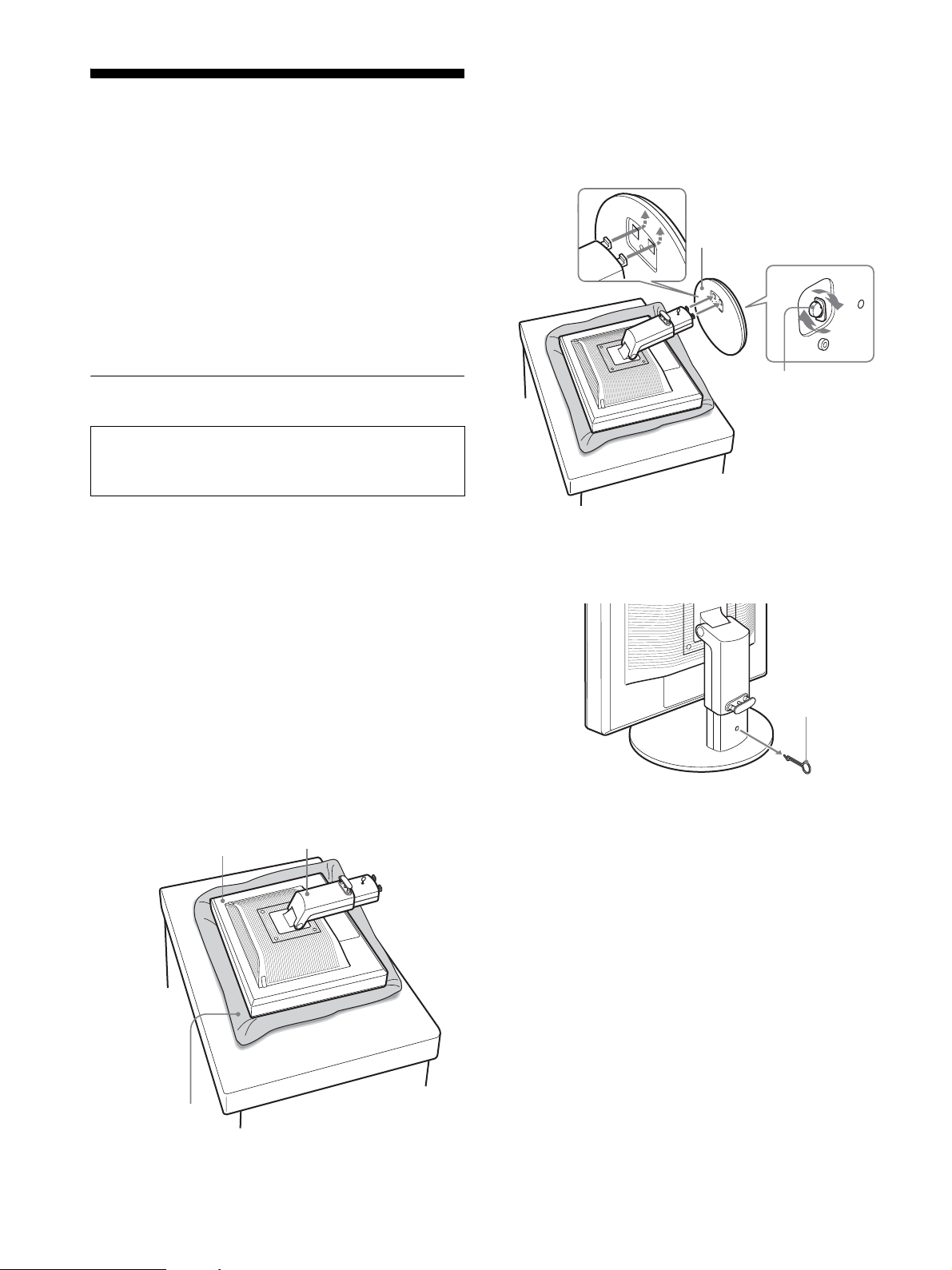
Step 1:Assemble the stand
Do not press the LCD display when placing or raising the
display straight on a desk or a like.
It may affect the uniformity of the screen or damage the
LCD display.
x When using supplied stand
1 Open the carton and take out the stand base.
2 Confirm the supplied items.
• Stand Base (with the screw at the bottom side)
5 Hook the stand base holes onto the prongs of stand
to attach. 1
Lift the handle of screw to screw the stand base
securely. 2
Be sure that the screw is secured and turn the screw
handle back.
1 Stand Base
2 Screw
6 If you use the height adjustable stand, remove the
stopper pin after raising the height adjustable stand
straight.
3 Place a soft mat or a kind on a flat surface like a
desk.
You may damage the LCD screen and the display itself if
putting the display directly on the desk.
4 Take the display out from the carton and then place
the frame of the laid display along the edge of the
desk.
The figure shows the height adjustable stand. If you use the
fixed stand, your last step of assembling procedure is Step 5.
Display
Stand
Stopper Pin
Note
Do not remove the stopper pin while the stand is laid. It may fall or injure
you by the stand neck coming off the stand base impetuously.
Soft mat or a like
6 (GB)
x When using VESA Stand
Screws
compatible with
VESA stand (4)
100 mm × 100 mm
You can attach a VESA stand in other brands by removing the
supplied stand attached to the display.
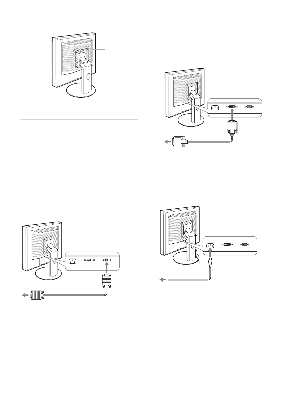
x Connect a computer equipped with a DVI
output connector (digital RGB)
(SDM-S76D/SDM-S96D/SDM-V76D/SDMV96D/SDM-S76F/SDM-S96F only)
Using the supplied DVI-D video signal cable (digital RGB),
connect the computer to the display’s DVI-D input connector
(digital RGB).
Step 2: Connect the display to your
computer
Turn off the display and computer then tilt the display up before
connecting.
Notes
• Do not touch the pins of the video signal cable connector as this might
bend the pins.
• Check the a lignment of the HD15 conne ctor to prevent bending the pins
of the video signal cable connector.
x Connect a computer equipped with an HD15
output connector (analog RGB)
Using the supplied HD15-HD15 video signal cable (analog
RGB), connect the computer to the display’s HD 15 input
connector (analog RGB).
to the DVI-D
to the computer’s DVI output
connector (digital RGB)
DVI-D video signal
cable (digital RGB)
(supplied)
input connector
(digital RGB)
Step 3:Connect the power cord
With the display and computer switched off, first connect the
power cord to the display, then connect it to a power outlet.
to AC IN
to the computer’s HD15 output
connector (analog RGB)
HD15-HD15 video signal
cable (analog RGB)
(supplied)
to the HD 15
input connector
(analog RGB)
to a power outlet
power cord (supplied)
7 (GB)
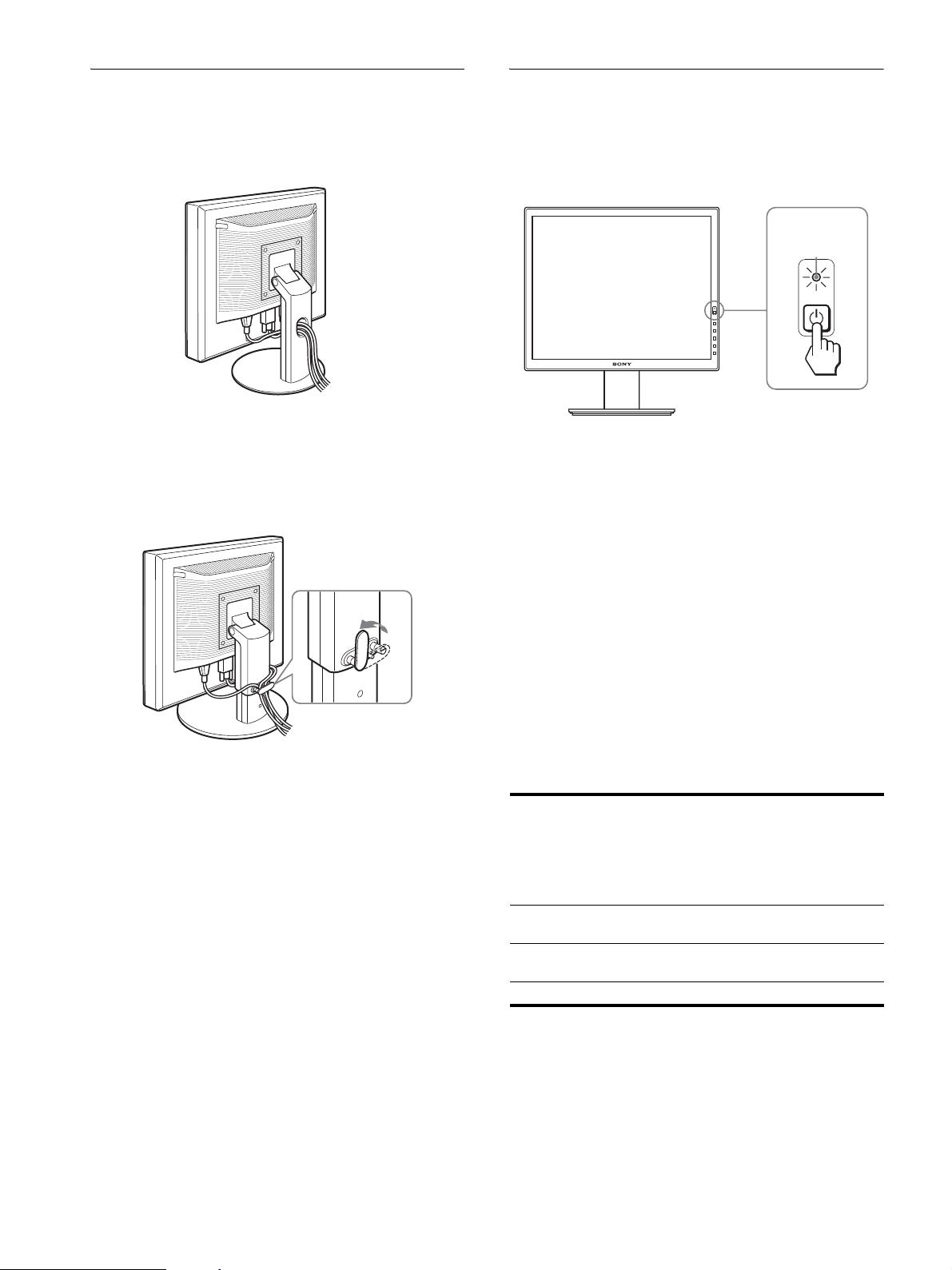
Step 4:Secure the cords
Step 5:Turn on the display and
x Fixed stand
Be sure that the cords and cables are fed through the stand hole as
illustrated.
The illustration of the back of the display shown here is that of
the SDM-S76D.
The same applies for the other models.
x Height adjustable stand
Draw the cords and cables through the cable holder as illustrated.
computer
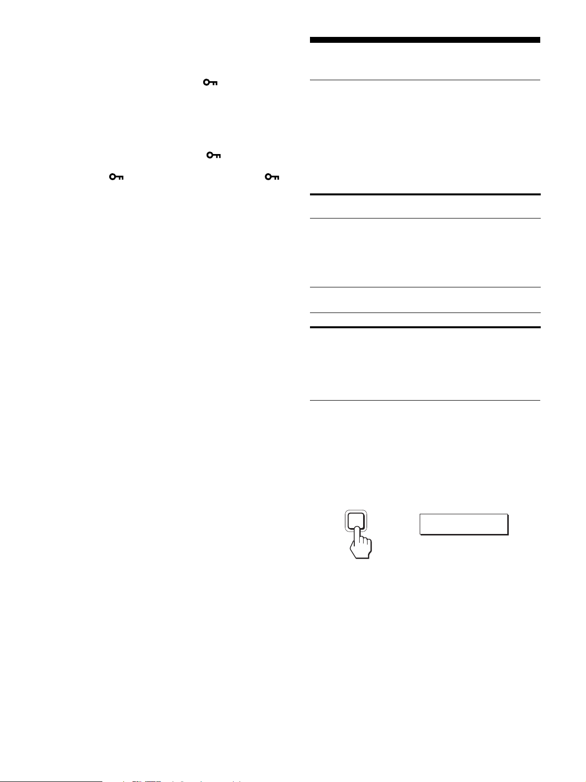
1 Press the 1 (power) switch located on the front
right of the display.
The 1 (power) indicator lights up in green.
lights in green
2 Turn on the computer.
The installation of your display is complete. If necessary, use the
display’s controls to adjust the picture.
If no picture appears on your screen
• Check that the power cord and the video signal cable are
properly connected.
Note
When bounding the cords and cables, be sure to loosen them a little. If
they get pulled hard they may come off from the connectors or plugs as
you adjust the screen angle. If you stretch the cords and cables too hard
they may get damaged.
• If NO INPUT SIGNAL appears on the screen:
The computer is in the power saving mode. Try pressing any
key on the keyboard or moving the mouse.
• If CABLE DISCONNECTED appears on the screen:
Check that the video signal cable is properly connected.
• If OUT OF RANGE appears on the screen:
Reconnect the old display. Then adjust the computer’s graphics
board within the following ranges.
Analog RGB Digital RGB
Horizontal
frequency
Ver tic al
frequency
Resolution 1280 × 1024 or less 1280 × 1024 or less
For more information about the on-screen messages, see “Trouble
symptoms and remedies” on page 18.
28–80 kHz 28–64 kHz
56–75 Hz 60 Hz
(SDM-S76D/
SDM-S96D/
SDM-V76D/
SDM-V96D/
SDM-S76F/
SDM-S96F only)
8 (GB)
No need for specific drivers
The display complies with the “DDC” Plug & Play standard and
automatically detects all the display’s information. No specific driver
needs to be installed to the computer.
The first time you turn on your computer after connecting the display, the
setup Wizard may appear on the screen. In this case, follow the on-screen
instructions. The Plug & Play display is automatically selected so that you
can use this display.
The vertical frequency turns to 60 Hz.
Since flickers are unobtrusive on the display, you can use it as it is. You
do not need to set the vertical frequency to any particular high value.
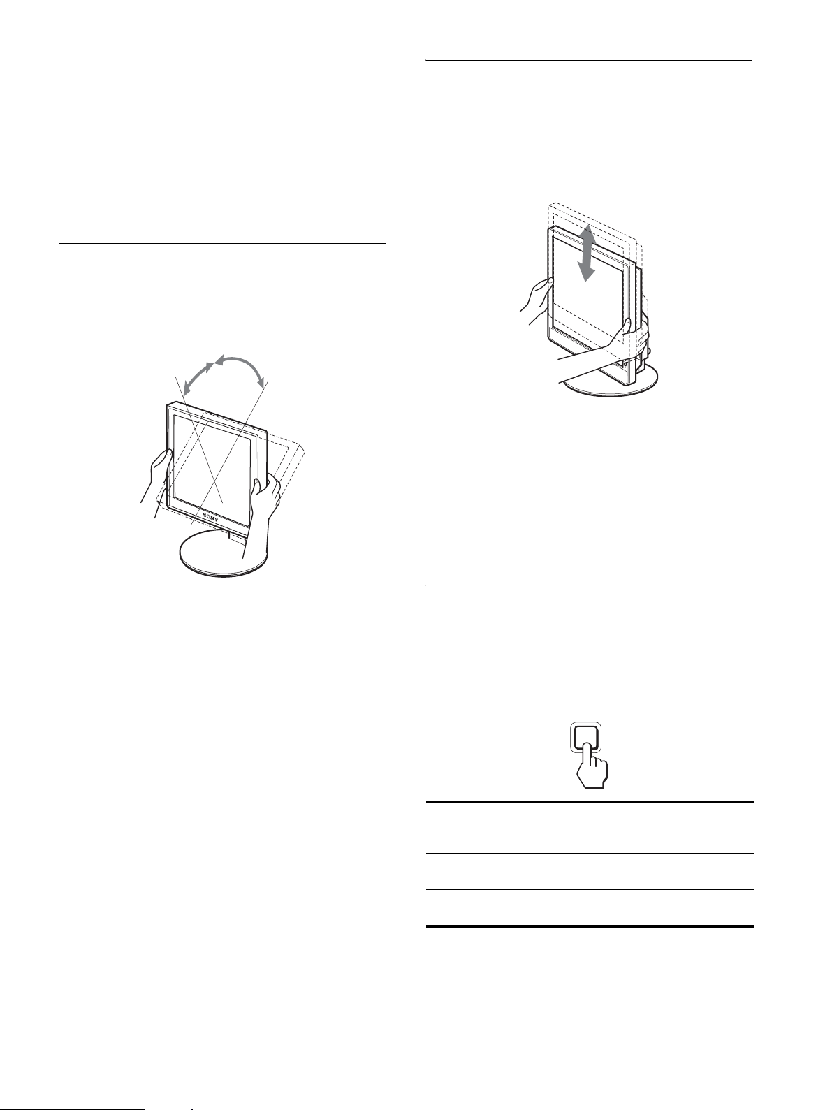
Adjusting the tilt
This display can be adjusted within the angles shown below.
Hold both sides of the LCD panel, then adjust screen
angles.
approx. 5°
approx. 20°
Adjusting the height
(SDM-S76F/SDM-S96F only)
When you use the height adjustable stand, the height adjust is also
available as below.
Hold both sides of the LCD panel, then adjust screen
height.
approx. 110 mm
11
(4
/32 inches)
To use the display comfortably
Adjust the viewing angle of your display according to the height
of your desk and chair, so that light is not reflected from the screen
to your eyes.
To use the display comfortably
This display is designed so that you can set it up at a comfortable
viewing angle. Adjust the viewing angle of your display
according to the height of the desk and chair, and so that light is
not reflected from the screen to your eyes.
Note
When adjusting the screen tilt, make sure not to knock or drop the display
off the desk.
Notes
• When adjusting the screen’s angle, be sure not to crash it against any
objects around the display.
• Do not put any objects under the display when you adjust the height of
stand. It may get damaged by accident.
Selecting the input signal
(INPUT button) (SDM-S76D/SDM-S96D/SDMV76D/SDM-V96D/SDM-S76F/SDM-S96F only)
Press the INPUT button.
The input signal change each time you press this button.
INPUT
OK
On-screen message
(Appears about 5 seconds on
the upper left corner.)
INPUT1 : DVI-D DVI-D input connector
INPUT2 : HD15 HD15 input connector
Input signal configuration
(digital RGB) for INPUT1
(analog RGB) for INPUT2
9 (GB)
Customizing Your Display
Before making adjustments
Connect the display and the computer, and turn them on.
Wait for at least 30 minutes before making adjustments for the
best result.
You can make numerous adjustments to your display using the
on-screen menu.
Adjusting to the desired
brightness
Pressing the ECO button, you can change the brightness of the
screen. Each time you press the ECO button, the ECO mode
changes as follows.
t MIDDLE t LOW t USER t HIGH ...
HIGH
The brightness of the screen will decrease as the ECO mode
setting changes from HIGH to LOW.
If you select USER, you can adjust the backlight level by pressing
the m/M buttons, the same as when you select BACKLIGHT
using the menu.
:
ECO USER
50
Only while the ECO mode is set to USER, are the BACKLIGHT,
CONTRAST, and BRIGHTNESS items of the menu available
(page 11, 12).
If you select LOW, the power consumption is reduced (page 16).
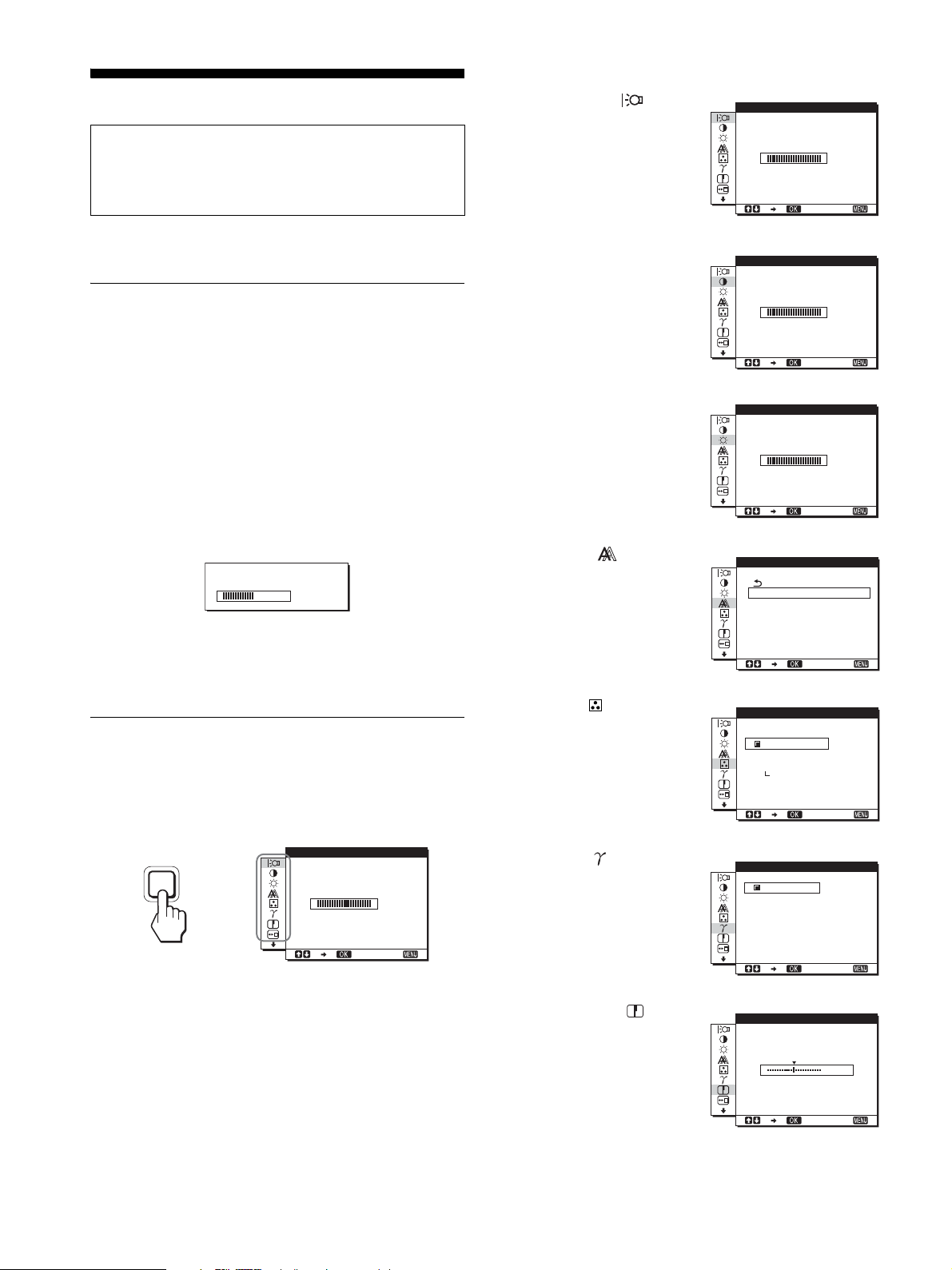
Navigating the menu
Press the MENU button to display the main menu on your screen.
See page 11 for more information on using the MENU button.
MENU
,
BACKL GHTI
100
1 BACKLIGHT
(page 11)
Select the BACKLIGHT
menu to adjust the brightness
of the backlight.
2 CONTRAST 6 (page 12)
Select the CONTRAST
menu to adjust the picture
contrast.
3 BRIGHTNESS 8
(page 12)
Select the BRIGHTNESS
menu to adjust the picture
brightness (black level).
4 SCREEN (page 12)
Select the SCREEN menu to
adjust the picture’s sharpness
(phase/pitch) or its centering
(horizontal/vertical position)
(analog RGB signal only).
5 COLOR (page 14)
Select the COLOR menu to
adjust the color temperature
of the picture. This adjusts
the tone of the screen. While
COLOR is set to sRGB, you
cannot adjust CONTRAST,
BRIGHTNESS or GAMMA.
6 GAMMA (page 14)
Select the GAMMA menu to
change the picture’s color
shade setting.
BACKL GHTI
100
1280 1024 60Hzx/
CONTRAST
1280 1024 60Hzx/
BR GHTNESSI
1280 1024 60Hzx/
SCREEN
AUTO ADJUST
PHASE
P I TCH
H CENTER
V CENTER
1280 1024 60Hzx/
COLOR
9300K
6500K
sRGB
USER
ADJUST
1280 1024 60Hzx/
GAMMA
GAMMA1
GAMMA2
GAMMA3
EX I T
100
EX I T
100
EX I T
EX I T
EX I T
1280 1024 60Hzx/
EX I T
Use the m/M and OK (INPUT) buttons to select the icons in the
above main menu illustration. The following 1 to 0 menu
appears. Keep pressing m to scroll down until the icons in menu
9 and 0 appear. See page 11 for more information on using the
m/M and OK (INPUT) buttons.
10 (GB)
7 SHARPNESS
(page 14)
Select the SHARPNESS
menu to adjust to sharpen the
edge of images.
1280 1024 60Hzx/
SHARPNESS
1280 1024 60Hzx/
EX I T
EX I T
5

8 MENU POSITION
(page 15)
Select the MENU
POSITION to change the onscreen menu position.
9 INPUT SENSING
(page 15) (SDM-S76D/
SDM-S96D/SDM-V76D/
SDM-V96D/SDM-S76F/
SDM-S96F only)
The display automatically
detects an input signal to an
input terminal, and changes
the input automatically
before the display goes into
the power saving mode.
MENU POS T ONII
1280 1024 60Hzx/
INPUT SENSING
AUTO ON
AUTO OFF
1280 1024 60Hzx/
EX I T
EX I T
3 Adjust the menu.
Press the m/M buttons to make the adjustment, then press the
OK button.
When you press the OK button, the setting is stored, then the
display returns to the previous menu.
INPUT
OK
,
4 Close the menu.
Press the MENU button once to return to normal viewing. If
no buttons are pressed, the menu closes automatically after
about 45 seconds.
MENU
0 LANGUAGE (page 15)
Select LANGUAGE to
change the language used on
menus or messages.
qa Other menus (page 15)
Set the following menu
items.
LANGUAGE
ENGL I SH
FRANÇA I S
DEUTSCH
ESPAÑOL
I TAL I ANO
1280 1024 60Hzx/
RESET
OK
CANCEL
EX I T
• RESET 0
• MENU LOCK
1280 1024 60Hzx/
EX I T
x Using the MENU, m/M, and OK buttons
1 Display the main menu.
Press the MENU button to display the main menu on your
screen.
MENU
x Resetting the adjustments
You can reset the adjustments using the RESET menu. See
page 15 for more information on resetting the adjustments.
x Controlling the display by computer
Press the MENU button down for at least 5 seconds. You will see
an on-screen message indicating the current setting. After 3
seconds the DDC/CI setting is switched on or off, as shown
below.
On-screen messages
(Appear for a while)
DDC-CI : ON
(default setting)
Allows the computer to control
menu settings.
DDC-CI : OFF Does not allow the computer to
control menu settings.
Note
This function applies only to computers that support the DDC/CI
(Display Data Channel Command Interface) function.
Adjusting the backlight
2 Select the menu you want to adjust.
Press the m/M buttons to display the desired menu. Press the
OK button to select the menu item.
INPUT
OK
,
(BACKLIGHT)
Note
The backlight cannot be adjusted when the ECO mode is set to
HIGH, MIDDLE, or LOW (page 10).
If the screen is too bright, adjust the backlight and make the screen
easier to see.
1 Press the MENU button.
The main menu appears on the screen.
2 Press the m/M buttons to select (BACKLIGHT)
and press the OK button.
The BACKLIGHT menu appears on the screen.
11 (GB)

3 Press the m/M buttons to adjust the light level and
press the OK button.
Adjusting the contrast
Notes
• While the automatic picture quality adjustment function is activated,
only the 1 (power) switch will operate.
• The picture may flicker during this time, but this is not a malfunction.
Simply wait a few moments until the adjustment completes.
(CONTRAST)
Adjust the picture contrast.
Notes
• The contrast cannot be adjusted when the ECO mode is set to HIGH,
MIDDLE, or LOW (
• While COLOR is set to sRGB, you cannot adjust CONTRAST,
BRIGHTNESS or GAMMA.
page 10).
1 Press the MENU button.
The main menu appears on the screen.
2 Press the m/M buttons to select 6 (CONTRAST) and
press the OK button.
The CONTRAST menu appears on the screen.
3 Press the m/M buttons to adjust the contrast and
press the OK button.
Adjusting the black level of an
image (BRIGHTNESS)
Adjust the picture brightness (black level).
Notes
• The brightness cannot be adjusted when the ECO mode is set to HIGH,
MIDDLE, or LOW (
• While COLOR is set to sRGB, you cannot adjust CONTRAST,
BRIGHTNESS or GAMMA.
page 10).
1 Press the MENU button.
The main menu appears on the screen.
2 Press the m/M buttons to select 8 (BRIGHTNESS)
and press the OK button.
The BRIGHTNESS menu appears on the screen.
3 Press the m/M buttons to adjust the brightness and
press the OK button.
Adjusting the picture’s sharpness
and centering (SCREEN)
(analog RGB signal only)
If the automatic picture quality adjustment function of
this display seems to not completely adjust the picture
You can make further automatic adjustment of the picture quality
for the current input signal. (See AUTO ADJUST below.)
If you still need to make further adjustments to the
picture quality
You can manually adjust the picture’s sharpness (phase/pitch) and
position (horizontal/vertical position).
These adjustments are stored in memory and automatically
recalled when the display receives the same input signal.
These settings may have to be repeated if you change the input
signal after reconnecting your computer.
x Make further automatic adjustments to the
picture quality for the current input signal
(AUTO ADJUST)
Set the optimum phase, pitch and horizontal/vertical position for
the current input signal.
1 Press the MENU button.
The main menu appears on the screen.
2 Press the m/M buttons to select (SCREEN) and
press the OK button.
The SCREEN menu appears on the screen.
3 Press the m/M buttons to select AUTO ADJUST and
press the OK button.
The AUTO ADJUST menu appears on the screen.
4 Press the m/M buttons to select OFF or ON and
press the OK button.
• OFF: AUTO ADJUST is not available.
Note
AUTO ADJUST works automatically when the input
signal is changed.
• ON: Make the appropriate adjustments of the screen's
phase, pitch and horizontal/vertical position for the
current input signal and store them.
Note
When the monitor is turned on or the input signal is
changed, AUTO ADJUST makes the automatic
adjustments.
x Automatic picture quality adjustment
function
When the display receives an input signal, it
automatically adjusts the picture’s position and
sharpness (phase/pitch), and ensures that a clear
picture appears on the screen (page 17).
12 (GB)
5 Press the m/M buttons to select and press the
OK button.
Return to the menu screen.
x Adjust the picture’s sharpness and position
manually (PITCH/PHASE/H CENTER/
VCENTER)
You can adjust the picture’s sharpness as follows. This
adjustment is effective when the computer is connected to the
monitor’s HD15 input connector (analog RGB).
1 Set the resolution to 1280 × 1024 on the computer.
2 Load the CD-ROM.
3 Start the CD-ROM
For Windows User
When Auto run operates:
Select the area, language and model, and click DISPLAY
ADJUSTMENT TOOL (UTILITY).
4 Click “Adjust” and confirm the current resolution
(top value) and recommended resolution (bottom
value), and then click “Next”.
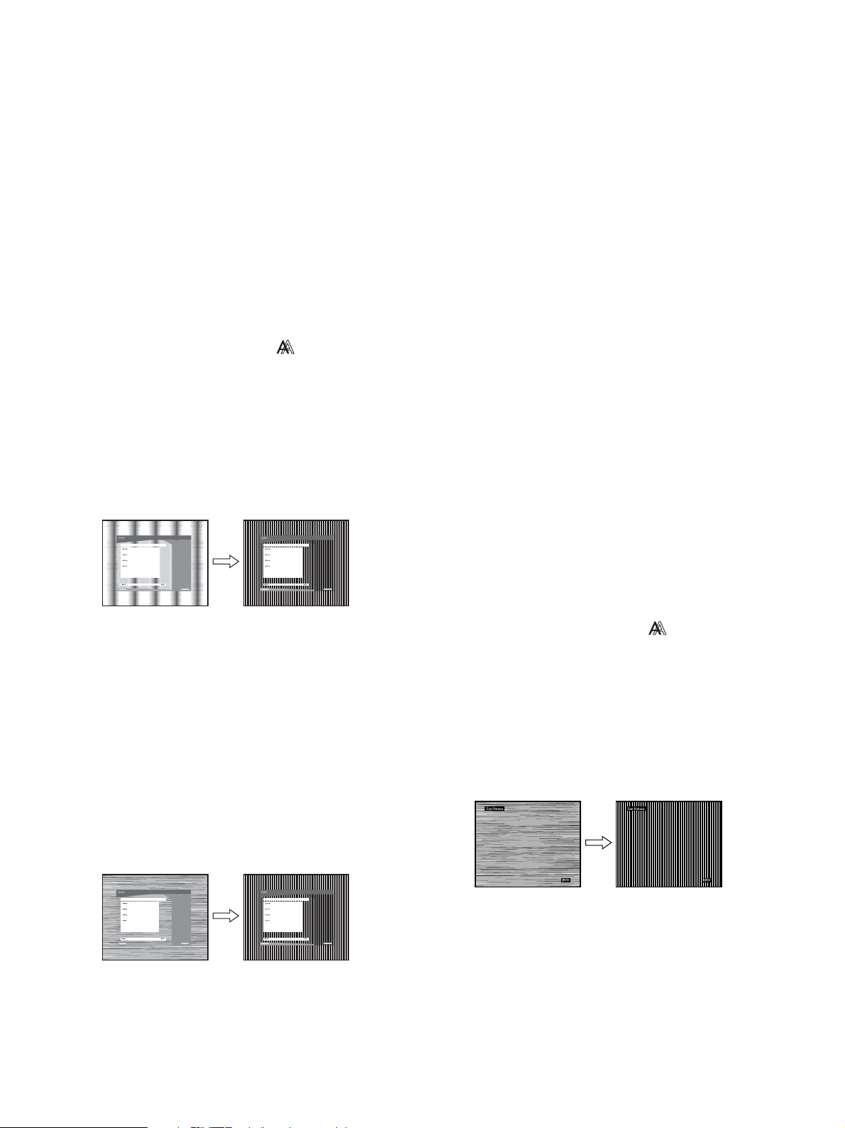
Test pattern for PITCH appears.
5 Press the MENU button.
The main menu appears on the screen.
6 Press the m/M buttons to select (SCREEN) and
press the OK button.
The SCREEN menu appears on the screen.
7 Press the m/M buttons to select PITCH and press the
OK button.
The PITCH adjustment menu appears on the screen.
8 Press the m/M buttons until the vertical stripes
disappear.
Adjust so that the vertical stripes disappear.
14 Click "Next".
Test pattern for CENTER appears.
15 Press the m/M buttons to select H CENTER or V
CENTER and press the OK button.
The H CENTER adjustment menu or V CENTER adjustment
menu appears on the screen.
16 Press the m/M buttons to center the test pattern on
the screen.
17 Click "Next".
Click "End" or "EXIT" to turn off the test pattern.
When Auto run fails to operate:
1 Open “My Computer” and right click the CD-ROM
icon.
Go to “Explorer” and open the CD-ROM icon.
2 Open [Utility] and then select [WINDOWS].
3 Start [WIN_UTILITY.EXE].
Test pattern appears. Go to step 4.
For Macintosh User
1 Open the CD-ROM.
2 Open [Utility] and then select [MAC].
3 Open [MAC UTILITY] and then start
[MAC_CLASSIC_UTILITY] or [MAC_OSX_UTILITY].
Test pattern appears. Go to step 4.
9 Press the OK button.
The main menu appears on the screen.
If horizontal stripes are observed over the entire screen, adjust
the PHASE using the following procedures.
10 Click "Next".
Test pattern for PHASE appears.
11 Press the m/M buttons to select PHASE and press
the OK button.
The PHASE adjustment menu appears on the screen.
12 Press the m/M buttons until the horizontal stripes
are at a minimum.
Adjust so that the horizontal stripes are at a minimum.
4 Press the MENU button.
The main menu appears on the screen.
5 Press the m/M buttons to select (SCREEN) and
press the OK button.
The SCREEN menu appears on the screen.
6 Press the m/M buttons to select PHASE and press
the OK button.
The PHASE adjustment menu appears on the screen.
7 Press the m/M buttons until the horizontal stripes
are at a minimum.
Adjust so that the horizontal stripes are at a minimum.
8 Press the OK button.
The main menu appears on the screen.
If vertical stripes are observed over the entire screen, adjust
the PITCH using the following procedures.
13 Press the OK button.
The main menu appears on the screen.
9 Press the m/M buttons to select PITCH and press the
OK button.
The PITCH adjustment menu appears on the screen.
13 (GB)
10 Press the m/M buttons until the vertical stripes
disappear.
Adjust so that the vertical stripes disappear.
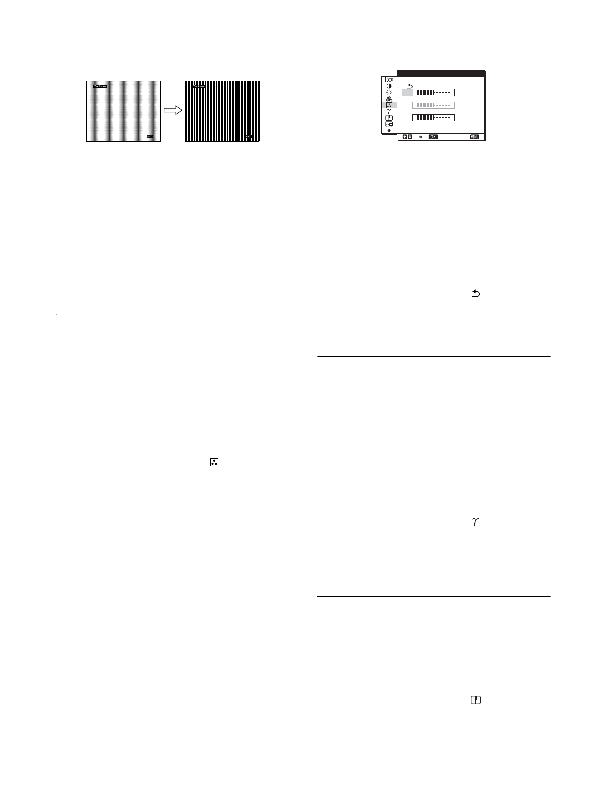
Fine tuning the color temperature
(USER ADJUSTMENT)
USER ADJ USTMENT
11 Press the OK button.
The main menu appears on the screen.
12 Press the m/M buttons to select H CENTER or V
CENTER and press the OK button.
The H CENTER adjustment menu or V CENTER adjustment
menu appears on the screen.
13 Press the m/M buttons to center the test pattern on
the screen.
14 Click “END” on the screen to turn off the test
pattern.
Adjusting the color temperature
(COLOR)
You can select the color level of the picture’s white color field
from the default color temperature settings.
Also, if necessary, you can fine tune the color temperature.
You can set the desired color temperature for each mode of the
brightness of screen.
1 Press the MENU button.
The main menu appears on the screen.
2 Press the m/M buttons to select (COLOR) and
press the OK button.
The COLOR menu appears on the screen.
3 Press the m/M buttons to select the desired color
temperature and press the OK button.
Whites will change from a bluish hue to reddish hue as the
temperature is lowered from 9300K to 6500K (default
setting).
When you select “sRGB,” the colors adjust to the sRGB
profile. (The sRGB color setting is an industry-standard color
space protocol designed for computer products.) If you select
“sRGB,” the color settings of your computer must be set to the
sRGB profile.
R
G
B
1280 1024 60Hzx/
1
Press the m/M buttons to select ADJUST and press
the OK button.
The USER ADJUSTMENT menu appears on the screen.
128
128
128
EX I T
2 Press the m/M buttons to select R (Red) or B (Blue)
and press the OK button. Then press the m/M
buttons to adjust the color temperature and press
the OK button.
Since this adjustment changes the color temperature by
increasing or decreasing the R and B components with respect
to G (green), the G component is fixed.
3 Press the m/M buttons to select , then press the
OK button.
The new color setting is stored in memory for USER and
automatically recalled whenever USER is selected.
The main menu appears on the screen.
Changing the gamma setting
(GAMMA)
You can associate the picture’s color shade on the screen with the
picture’s original color shade.
Note
While COLOR is set to sRGB, you cannot adjust CONTRAST,
BRIGHTNESS or GAMMA.
1 Press the MENU button.
The main menu appears on the screen.
2 Press the m/M buttons to select (GAMMA) and
press the OK button.
The GAMMA menu appears on the screen.
3 Press the m/M buttons to select the desired mode
and press the OK button.
Adjusting the sharpness
Notes
• If a connected computer or other equipment is not sRGB-compliant,
color cannot be adjusted to the sRGB profile.
• While COLOR is set to sRGB, you cannot adjust CONTRAST,
BRIGHTNESS or GAMMA.
(SHARPNESS)
Adjust to sharpen the edge of images, etc.
1 Press the MENU button.
The main menu appears on the screen.
2 Press the m/M buttons to select (SHARPNESS)
and press the OK button.
The SHARPNESS menu appears on the screen.
14 (GB)
3 Press the m/M buttons to adjust the sharpness and
press the OK button.
Changing the menu’s position
(MENU POSITION)
Selecting the on-screen menu
language (LANGUAGE)
You can change the language used on menus or messages
displayed on this display.
You can change the menu position if it is blocking an image on
the screen.
1 Press the MENU button.
The main menu appears on the screen.
2 Press the m/M buttons to select (MENU
POSITION) and press the OK button.
The MENU POSITION menu appears on the screen.
3 Press the m/M buttons to select the desired position
and press the OK button.
There are three positions each for the top, center and bottom
of the screen.
Changing the input automatically
(INPUT SENSING)
(SDM-S76D/SDM-S96D/SDM-V76D/
SDM-V96D/SDM-S76F/SDM-S96F
only)
When you select AUTO ON in the INPUT SENSING menu, the
display automatically detects an input signal to an input terminal,
and changes the input automatically before the display goes into
the power saving mode.
1 Press the MENU button.
The main menu appears on the screen.
2 Keep pressing the m button until the icon of the
desired option item appears.
3 Press the m/M buttons to select (LANGUAGE)
and press the OK button.
The LANGUAGE menu appears on the screen.
4 Press the m/M buttons to select a language and
press the OK button.
•ENGLISH
• FRANÇAIS: French
• DEUTSCH: German
• ESPAÑOL: Spanish
• ITALIANO: Italian
• NEDERLANDS: Dutch
• SVENSKA: Swedish
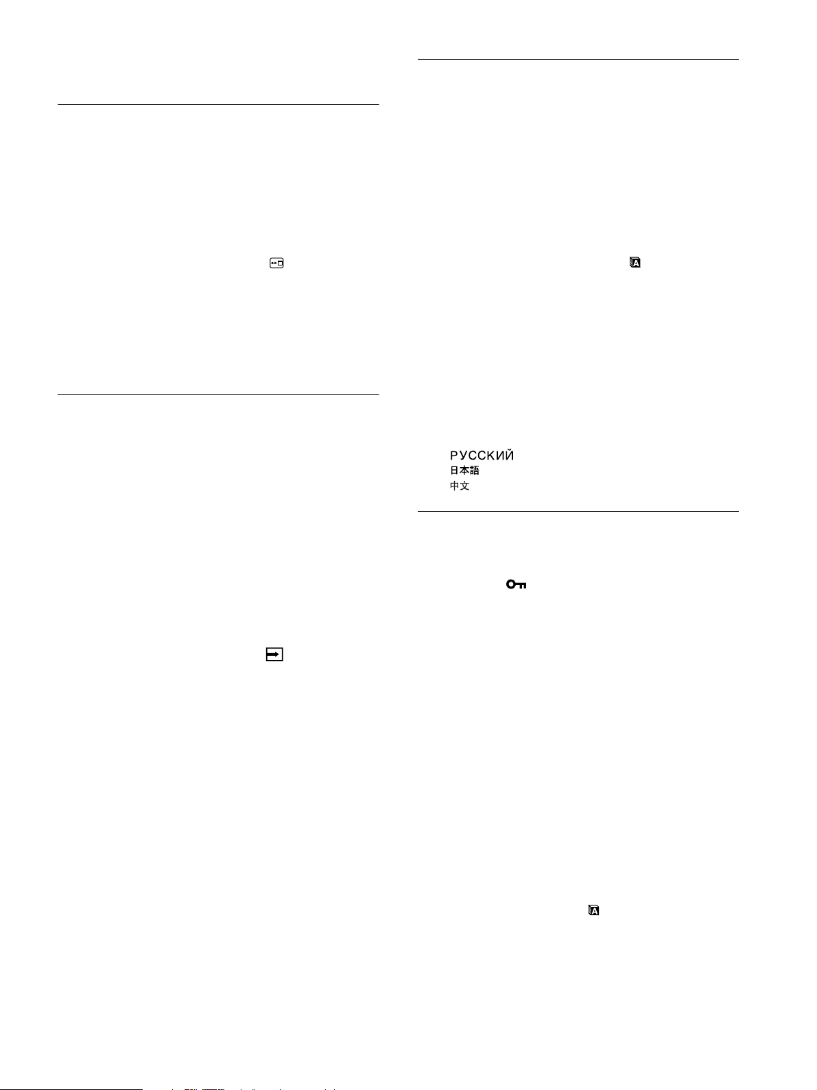
• : Russian
• : Japanese
•: Chinese
Additional settings
You can adjust the following options:
• RESET 0
•MENU LOCK
1 Press the MENU button.
The main menu appears on the screen.
2 Press the m/M buttons to select (INPUT
SENSING) and press the OK button.
The INPUT SENSING menu appears on the screen.
3 Press the m/M buttons to select the desired mode
and press the OK button.
• AUTO ON: When the selected input terminal has no
input signal, or when you select an input
terminal by the INPUT button on the
display and the terminal has no input
signal, the on-screen message appears
(page 17) and the display checks the input
signal to another input terminal
automatically to change the input.
When the input is changed, the selected
input terminal is displayed on the left upper
of the screen.
When there is no input signal, the display
goes into the power saving mode
automatically.
• AUTO OFF: The input is not changed automatically.
Press the INPUT button to change the
input.
1 Press the MENU button.
The main menu appears on the screen.
2 Keep pressing the m button until the icon of the
desired option item appears.
3 Press the m/M buttons to select the desired option
item and press the OK button.
Adjust the selected option item according to the following
instructions.
x
Resetting the adjustment data to the defaults
You can reset the adjustments to the default settings.
1 Press the m/M buttons to select 0 (RESET) and
press the OK button.
The RESET menu appears on the screen.
2 Press the m/M buttons to select the desired mode
and press the OK button.
• OK: To reset all of the adjustment data to the default
settings. Note that the (LANGUAGE) setting is
not reset by this method.
• CANCEL:To cancel resetting and return to the menu
screen.
15 (GB)
x Locking the menus and controls
You can lock the control of buttons to prevent accidental
adjustments or resetting.
Technical Features
1 Press the m/M buttons to select (MENU LOCK)
and press the OK button.
The MENU LOCK menu appears on the screen.
2 Press the m/M buttons to select ON or OFF and
press the OK button.
• ON:Only the 1 (power) switch will operate. If you
attempt any other operation, the (MENU LOCK)
icon appears on the screen.
• OFF:Set (MENU LOCK) to OFF. If you set the
(MENU LOCK) item to ON, only this menu item can
be selected.
Power saving function
This display meets the power-saving guidelines set by VESA,
ENERGY STAR, and NUTEK. If the display is connected to a
computer or video graphics board that is DPMS (Display Power
Management Standard) for Analog input/DMPM (DVI Digital
Monitor Power Management) for Digital input compliant, the
display will automatically reduce power consumption as shown
below.
Power mode Power consumption 1 (power)
normal
operation
active off*
(deep sleep)**
power off 1.0W(max.) off
* When your computer enters the “active off” mode, the input signal is
cut and NO INPUT SIGNAL appears on the screen. After 5 seconds,
the display enters the power saving mode.
** “deep sleep” is the power saving mode defined by the Environmental
Protection Agency.
38W(max.)
(SDM-S76A/SDM-S76D/
SDM-V76D/SDM-S76F)
44W(max.)
(SDM-S96A/SDM-S96D/
SDM-V96D/SDM-S96F)
1.0W(max.) orange
indicator
green
Reducing the power consumption
(ECO mode)
If you set the ECO mode to LOW by pressing the ECO button on
the front of the display, the backlight level is reduced and the
power consumption is reduced, too.
Press the ECO button several times until LOW appears.
ECO
,
LOW appears on the screen and the backlight level is reduced.
LOW automatically disappears after about 5 seconds.
:
ECO LOW
16 (GB)
Automatic picture quality
adjustment function
(analog RGB signal only)
Troubleshooting
Before contacting technical support, refer to this section.
When the display receives an input signal, it
automatically adjusts the picture’s position and
sharpness (phase/pitch), and ensures that a clear
picture appears on the screen.
The factory preset mode
When the display receives an input signal, it automatically
matches the signal to one of the factory preset modes stored in the
display’s memory to provide a high quality picture at the center of
the screen. If the input signal matches the factory preset mode, the
picture appears on the screen automatically with the appropriate
default adjustments.
If input signals do not match one of the factory
preset modes
When the display receives an input signal that does not match one
of the factory preset modes, the automatic picture quality
adjustment function of this display is activated to ensure that a
clear picture always appears on the screen (within the following
display frequency ranges):
Horizontal frequency: 28–80 kHz
Vertical frequency: 56–75 Hz
Consequently, the first time the display receives input signals that
do not match one of the factory preset modes, the display may
take a longer time than normal to display the picture on the screen.
This adjustment data is automatically stored in memory so that
next time, the display will function in the same way as when the
display receives the signals that match one of the factory preset
modes.
Note (SDM-S76D/SDM-S96D/SDM-V76D/SDM-V96D/SDMS76F/SDM-S96F only)
There is no need to adjust the digital RGB signals of the DVI-D input
connector for INPUT1.
On-screen messages
If there is something wrong with the input signal, one of the
following messages appears on the screen. To solve the problem,
see “Trouble symptoms and remedies” on page 18.
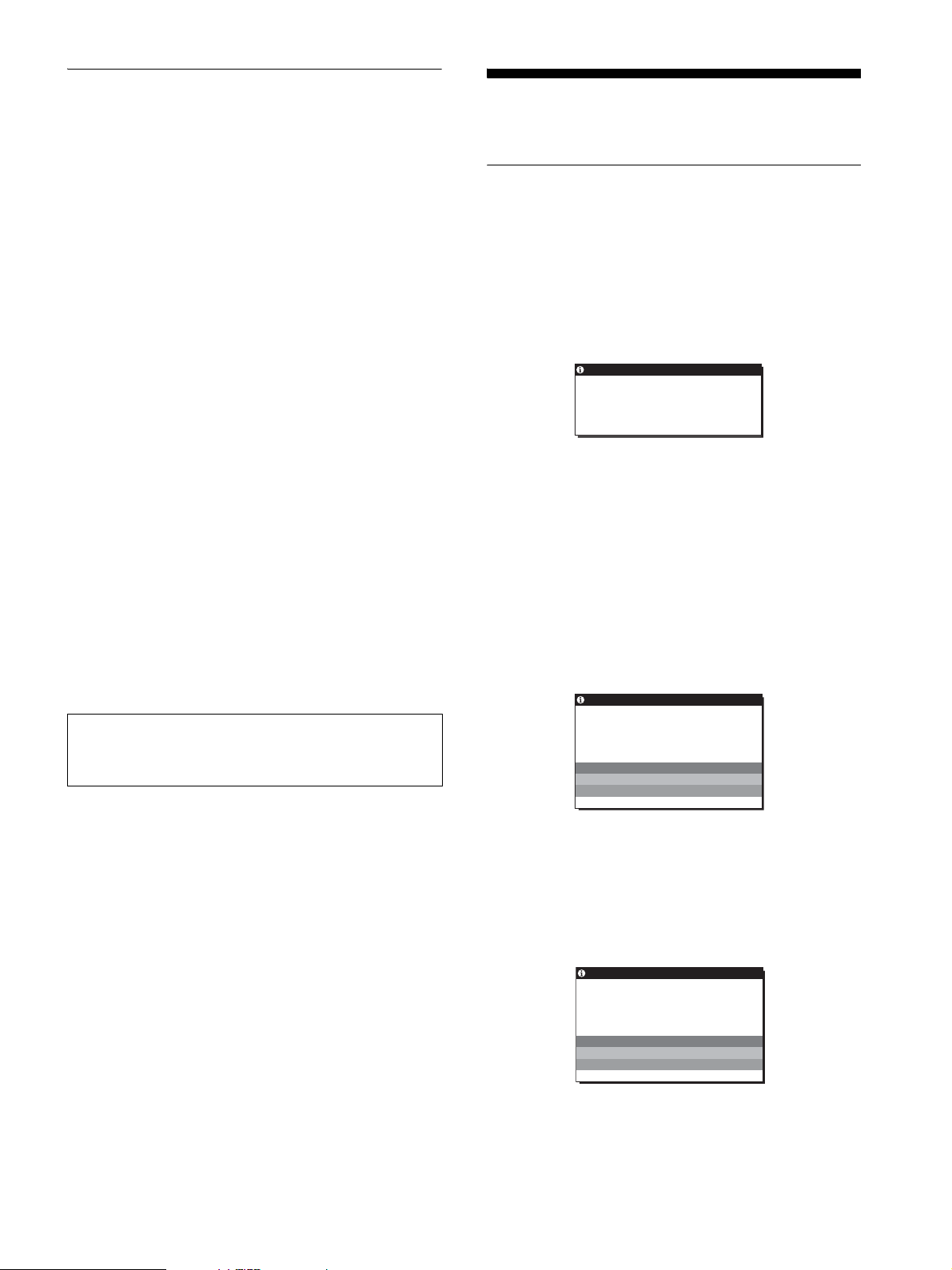
If OUT OF RANGE appears on the screen
This indicates that the input signal is not supported by the
display’s specifications. Check the following items.
Example
INFORMAT ION
OUT OF RANGE
INPUT1:DVI–D
xxx.xkHz/ xxxHz
If “xxx.x kHz/xxx Hz” is displayed
This indicates that either the horizontal or vertical frequency
is not supported by the display’s specifications.
The figures indicate the horizontal and vertical frequencies of
the current input signal.
If “RESOLUTION > 1280 × 1024” is displayed
This indicates that the resolution is not supported by the
display’s specifications (1280 × 1024 or less).
If NO INPUT SIGNAL appears on the screen
This indicates that no signal is being input.
Example
INFORMAT ION
NO I NPUT S I GNAL
INPUT1:DVI–D
GO TO POWER SAVE
If you adjust the phase, pitch and picture position
manually while OFF of AUTO ADJUST is selected
For some input signals, the automatic picture quality adjustment
function of this display may not completely adjust the picture
position, phase, and pitch. In this case, you can set these
adjustments manually (page 12). If you set these adjustments
manually, they are stored in memory as user modes and
automatically recalled whenever the display receives the same
input signals.
Notes
• While the automatic picture quality adjustment function is activated,
only the 1 (power) switch will operate.
• The picture may flicker during this time, but this is not a malfunction.
Simply wait a few moments until the adjustment completes.
GO TO POWER SAVE
The display will enter the power saving mode after about 5
seconds from the time the message is displayed.
If CABLE DISCONNECTED appears on the screen
This indicates that the video signal cable has been disconnected.
Example
INFORMAT ION
CAB L E D I SCONNECTED
INPUT1:DVI–D
GO TO POWER SAVE
GO TO POWER SAVE
The display will enter the power saving mode after about 45
seconds from the time the message is displayed.
17 (GB)
Trouble symptoms and remedies
If a problem is caused by the connected computer or other equipment, please refer to the connected equipment’s instruction manual.
Symptom Check these items
No picture
If the 1 (power) indicator is not lit
after power cord is connected,
or if the 1 (power) indicator is not
lit after the power switch is pressed,
If CABLE DISCONNECTED
appears on the screen,
If NO INPUT SIGNAL appears on
the screen, or the 1 (power)
indicator is orange,
If OUT OF RANGE appears on the
screen,
If you are using Windows and
replaced an old display with this
display,
If using a Macintosh system, • If you use the Macintosh adapter (not supplied), check that the Macintosh adapter and the
• Check that the power cord is properly connected.
• Check that the video signal cable is properly connected and all plugs are firmly seated in
their sockets (page 7).
• Check that the video input connector’s pins are not bent or pushed in.
• Check that the input select setting is correct (page 9).
• A non-supplied video signal cable is connected. If you connect a non-supplied video
signal cable, CABLE DISCONNECTED may appear on the screen before entering the
power saving mode. This is not a malfunction.
• Check that the video signal cable is properly connected and all plugs are firmly seated in
their sockets (page 7).
• Check that the video input connector’s pins are not bent or pushed in.
• Check that the input select setting is correct (page 9).
x Problems caused by a computer or other equipment connected, and not
caused by the display
• The computer is in the power saving mode. Try pressing any key on the keyboard or
moving the mouse.
• Check that your graphics board is installed properly.
• Change your graphic board to the latest driver. Or match the version of your graphic board
to the current OS.
• When using a laptop computer, set the output of your computer to video out (for details on
video out setting, contact your computer manufacturer).
• Check that the computer’s power is on.
• Restart the computer.
x Problems caused by a computer or other equipment connected, and not
caused by the display
• Check that the video frequency range is within that specified for the display. If you
replaced an old display with this display, reconnect the old display and adjust the
computer’s graphics board within the following ranges:
Horizontal: 28–80 kHz (analog RGB), 28–64 kHz (digital RGB for SDM-S76D/SDMS96D/SDM-V76D/SDM-V96D/SDM-S76F/SDM-S96F only)
Vertical: 56–75 Hz (analog RGB), 60 Hz (digital RGB for SDM-S76D/SDM-S96D/
SDM-V76D/SDM-V96D/SDM-S76F/SDM-S96F only)
Resolution: 1280 × 1024 or less
• Start your OS in Safe mode and restart the computer after setting the resolution. The
setting of safe mode varies depending on your OS. For more details, contact your
computer manufacturer.
• If you replaced an old display with this display, reconnect the old display and do the
following. Select “SONY” from the “Manufacturers” list and select the desired model
name from the “Models” list in the Windows device selection screen. If the model name
of this display does not appear in the “Models” list, try “Plug & Play.”
video signal cable are properly connected.
18 (GB)
Symptom Check these items
Picture flickers, bounces,
oscillates, or is scrambled
Picture is fuzzy • Adjust the brightness and contrast (page 12).
Picture is ghosting • Eliminate the use of video cable extensions and/or video switch boxes.
Picture is not centered or sized
properly
Picture is too small x Problems caused by a computer or other equipment connected, and not
Picture is dark • Adjust the brightness using the BRIGHTNESS menu (page 12).
Wavy or elliptical pattern (moire)
is visible
Color is not uniform • Adjust the pitch and phase (page 12).
White does not look white • Adjust the color temperature (page 14).
Display buttons do not operate
( appears on the screen)
The display turns off after a while x Problems caused by a computer or other equipment connected, and not
Resolution displayed on the menu
screen is incorrect
• Adjust the pitch and phase (page 12).
• Try plugging the display into a different AC outlet, preferably on a different circuit.
x Problems caused by a computer or other equipment connected, and not
caused by the display
• Check your graphics board manual for the proper display setting.
• Confirm that the graphics mode (VESA, Macintosh 19" Color, etc.) and the frequency of
the input signal are supported by this display. Even if the frequency is within the proper
range, some graphics boards may have a sync pulse that is too narrow for the display to
sync correctly.
• Adjust the computer’s refresh rate (vertical frequency) to obtain the best possible picture.
• Adjust the pitch and phase (page 12).
x Problems caused by a computer or other equipment connected, and not
caused by the display
• Set the resolution to 1280 × 1024 on your computer.
• Check that all plugs are firmly seated in their sockets.
• Adjust the pitch and phase (page 12).
• Adjust the picture position (page 12). Note that some video modes do not fill the screen to
the edges.
caused by the display
• Set the resolution to 1280 × 1024 on your computer.
• Adjust the backlight (page 11).
• It takes a few minutes for the display to become bright after turning on the display.
• Adjust the pitch and phase (page 12).
• If the menu lock is set to ON, set it to OFF (page 16).
caused by the display
• Set the computer’s power saving setting to off.
• Depending on the graphics board setting, the resolution displayed on the menu screen
may not coincide with the one set on the computer.
If any problem persists, call your authorized Sony dealer and give
the following information:
• Model name: SDM-S76A, SDM-S96A, SDM-S76D, SDMS96D, SDM-V76D, SDM-V96D, SDM-S76F or SDM-S96F
• Serial number
• Detailed description of the problem
• Date of purchase
• Name and specifications of your computer and graphics board
19 (GB)

Specifications
SDM-S76A
LCD panel Panel type: a-Si TFT Active Matrix
Picture size: 17.0 inch
Input signal format RGB operating frequency*
Horizontal: 28–80 kHz (analog RGB)
Vertical: 56–75 Hz (analog RGB)
Resolution Horizontal: Max.1280 dots
Vertical: Max.1024 lines
Input signal levels Analog RGB video signal
0.7 Vp-p, 75 Ω, positive
SYNC signal
TTL level, 2.2 kΩ,
positive or negative
(Separate horizontal and vertical)
Power requirements 100–240 V, 50–60 Hz,
Max. 1.0 A
Operating temperature 5–35
Dimensions (width/height/depth)
Mass Approx. 6 kg (13 lb 3 5/8 oz)
Plug & Play DDC2B
Accessories See page 6.
°C
Approx. 369 × 423.5 × 225 mm
5
/8 × 16 3/4 × 8 7/8 inches)
(14
(with stand)
Approx. 369 × 315 × 66 mm
5
/8 × 12 3/8 × 2 5/8 inches)
(14
(without stand)
(with stand)
Approx. 4 kg (8 lb 13 1/8 oz)
(without stand)
SDM-S96A
LCD panel Panel type: a-Si TFT Active Matrix
Picture size: 19.0 inch
Input signal format RGB operating frequency*
Horizontal: 28–80 kHz (analog RGB)
Vertical: 56–75 Hz (analog RGB)
Resolution Horizontal: Max.1280 dots
Vertical: Max.1024 lines
Input signal levels Analog RGB video signal
0.7 Vp-p, 75 Ω, positive
SYNC signal
TTL level, 2.2 kΩ,
positive or negative
(Separate horizontal and vertical)
Power requirements 100–240 V, 50–60 Hz,
Max. 1.0 A
Operating temperature 5–35
Dimensions (width/height/depth)
Mass Approx. 6.5 kg (14 lb 5 1/4 oz)
Plug & Play DDC2B
Accessories See page 6.
°C
Approx. 414 × 439.5 × 225 mm
3
/8 × 17 3/8 × 8 7/8 inches)
(16
(with stand)
Approx. 414 × 348 × 69 mm
3
/8 × 13 3/4 × 2 3/4 inches)
(16
(without stand)
(with stand)
Approx. 4.5 kg (9 lb 14
(without stand)
3
/4 oz)
* Recommended horizontal and vertical timing condition
• Horizontal sync width duty should be more than 4.8% of total
horizontal time or 0.8 µs, whichever is larger.
• Horizontal blanking width should be more than 2.5 µsec.
• Vertical blanking width should be more than 450 µsec.
Design and specifications are subject to change without notice.
20 (GB)

SDM-S76D
LCD panel Panel type: a-Si TFT Active Matrix
Picture size: 17.0 inch
Input signal format RGB operating frequency*
Horizontal: 28–80 kHz (analog RGB)
28–64 kHz (digital RGB)
Vertical: 56–75 Hz (analog RGB)
60 Hz (digital RGB)
Resolution Horizontal: Max.1280 dots
Vertical: Max.1024 lines
Input signal levels Analog RGB video signal
0.7 Vp-p, 75 Ω, positive
SYNC signal
TTL level, 2.2 kΩ,
positive or negative
(Separate horizontal and vertical)
Digital RGB (DVI) signal: TMDS
(Single link)
Power requirements 100–240 V, 50–60 Hz,
Max. 1.0 A
Operating temperature 5–35
Dimensions (width/height/depth)
Mass Approx. 6 kg (13 lb 3 5/8 oz)
Plug & Play DDC2B
Accessories See page 6.
°C
Approx. 369 × 423.5 × 225 mm
5
/8 × 16 3/4 × 8 7/8 inches)
(14
(with stand)
Approx. 369 × 315 × 66 mm
5
/8 × 12 3/8 × 2 5/8 inches)
(14
(without stand)
(with stand)
Approx. 4 kg (8 lb 13 1/8 oz)
(without stand)
SDM-S96D
LCD panel Panel type: a-Si TFT Active Matrix
Picture size: 19.0 inch
Input signal format RGB operating frequency*
Horizontal: 28–80 kHz (analog RGB)
28–64 kHz (digital RGB)
Vertical: 56–75 Hz (analog RGB)
60 Hz (digital RGB)
Resolution Horizontal: Max.1280 dots
Vertical: Max.1024 lines
Input signal levels Analog RGB video signal
0.7 Vp-p, 75 Ω, positive
SYNC signal
TTL level, 2.2 kΩ,
positive or negative
(Separate horizontal and vertical)
Digital RGB (DVI) signal: TMDS
(Single link)
Power requirements 100–240 V, 50–60 Hz,
Max. 1.0 A
Operating temperature 5–35
Dimensions (width/height/depth)
Mass Approx. 6.5 kg (14 lb 5 1/4 oz)
Plug & Play DDC2B
Accessories See page 6.
°C
Approx. 414 × 439.5 × 225 mm
3
/8 × 17 3/8 × 8 7/8 inches)
(16
(with stand)
Approx. 414 × 348 × 69 mm
3
/8 × 13 3/4 × 2 3/4 inches)
(16
(without stand)
(with stand)
Approx. 4.5 kg (9 lb 14 3/4 oz)
(without stand)
* Recommended horizontal and vertical timing condition
• Horizontal sync width duty should be more than 4.8% of total
horizontal time or 0.8 µs, whichever is larger.
• Horizontal blanking width should be more than 2.5 µsec.
• Vertical blanking width should be more than 450 µsec.
Design and specifications are subject to change without notice.
21 (GB)

SDM-V76D
LCD panel Panel type: a-Si TFT Active Matrix
Picture size: 17.0 inch
Input signal format RGB operating frequency*
Horizontal: 28–80 kHz (analog RGB)
28–64 kHz (digital RGB)
Vertical: 56–75 Hz (analog RGB)
60 Hz (digital RGB)
Resolution Horizontal: Max.1280 dots
Vertical: Max.1024 lines
Input signal levels Analog RGB video signal
0.7 Vp-p, 75 Ω, positive
SYNC signal
TTL level, 2.2 kΩ,
positive or negative
(Separate horizontal and vertical)
Digital RGB (DVI) signal: TMDS
(Single link)
Power requirements 100–240 V, 50–60 Hz,
Max. 1.0 A
Operating temperature 5–35
Dimensions (width/height/depth)
Mass Approx. 6 kg (13 lb 3 5/8 oz)
Plug & Play DDC2B
Accessories See page 6.
°C
Approx. 369 × 423.5 × 225 mm
5
/8 × 16 3/4 × 8 7/8 inches)
(14
(with stand)
Approx. 369 × 315 × 66 mm
5
/8 × 12 3/8 × 2 5/8 inches)
(14
(without stand)
(with stand)
Approx. 4 kg (8 lb 13 1/8 oz)
(without stand)
SDM-V96D
LCD panel Panel type: a-Si TFT Active Matrix
Picture size: 19.0 inch
Input signal format RGB operating frequency*
Horizontal: 28–80 kHz (analog RGB)
28–64 kHz (digital RGB)
Vertical: 56–75 Hz (analog RGB)
60 Hz (digital RGB)
Resolution Horizontal: Max.1280 dots
Vertical: Max.1024 lines
Input signal levels Analog RGB video signal
0.7 Vp-p, 75 Ω, positive
SYNC signal
TTL level, 2.2 kΩ,
positive or negative
(Separate horizontal and vertical)
Digital RGB (DVI) signal: TMDS
(Single link)
Power requirements 100–240 V, 50–60 Hz,
Max. 1.0 A
Operating temperature 5–35
Dimensions (width/height/depth)
Mass Approx. 6.5 kg (14 lb 5 1/4 oz)
Plug & Play DDC2B
Accessories See page 6.
°C
Approx. 414 × 439.5 × 225 mm
3
/8 × 17 3/8 × 8 7/8 inches)
(16
(with stand)
Approx. 414 × 348 × 69 mm
3
/8 × 13 3/4 × 2 3/4 inches)
(16
(without stand)
(with stand)
Approx. 4.5 kg (9 lb 14 3/4 oz)
(without stand)
* Recommended horizontal and vertical timing condition
• Horizontal sync width duty should be more than 4.8% of total
horizontal time or 0.8 µs, whichever is larger.
• Horizontal blanking width should be more than 2.5 µsec.
• Vertical blanking width should be more than 450 µsec.
Design and specifications are subject to change without notice.
22 (GB)

SDM-S76F
LCD panel Panel type: a-Si TFT Active Matrix
Picture size: 17.0 inch
Input signal format RGB operating frequency*
Horizontal: 28–80 kHz (analog RGB)
28–64 kHz (digital RGB)
Vertical: 56–75 Hz (analog RGB)
60 Hz (digital RGB)
Resolution Horizontal: Max.1280 dots
Vertical: Max.1024 lines
Input signal levels Analog RGB video signal
0.7 Vp-p, 75 Ω, positive
SYNC signal
TTL level, 2.2 kΩ,
positive or negative
(Separate horizontal and vertical)
Digital RGB (DVI) signal: TMDS
(Single link)
Power requirements 100–240 V, 50–60 Hz,
Max. 1.0 A
Operating temperature 5–35
Dimensions (width/height/depth)
Mass Approx. 7 kg (15 lb 6
Plug & Play DDC2B
Accessories See page 6.
°C
Approx. 369 × 393.5 – 503.5
× 253 mm
(14 5/8 × 15 1/2 – 19 7/8 × 10
inches) (with stand)
Approx. 369 × 315 × 66 mm
5
/8 × 12 3/8 × 2 5/8 inches)
(14
(without stand)
7
/8 oz)
(with stand)
Approx. 4 kg (8 lb 13 1/8 oz)
(without stand)
SDM-S96F
LCD panel Panel type: a-Si TFT Active Matrix
Picture size: 19.0 inch
Input signal format RGB operating frequency*
Horizontal: 28–80 kHz (analog RGB)
28–64 kHz (digital RGB)
Vertical: 56–75 Hz (analog RGB)
60 Hz (digital RGB)
Resolution Horizontal: Max.1280 dots
Vertical: Max.1024 lines
Input signal levels Analog RGB video signal
0.7 Vp-p, 75 Ω, positive
SYNC signal
TTL level, 2.2 kΩ,
positive or negative
(Separate horizontal and vertical)
Digital RGB (DVI) signal: TMDS
(Single link)
Power requirements 100–240 V, 50–60 Hz,
Max. 1.0 A
Operating temperature 5–35
Dimensions (width/height/depth)
Mass Approx. 7.5 kg (16 lb 8
Plug & Play DDC2B
Accessories See page 6.
°C
Approx. 414 × 409.5 – 519.5
× 277.5 mm
(16 3/8 × 16 1/8 – 20 1/2 × 11
inches) (with stand)
Approx. 414 × 348 × 69 mm
3
/8 × 13 3/4 × 2 3/4 inches)
(16
(without stand)
1
/2 oz)
(with stand)
Approx. 4.5 kg (9 lb 14 3/4 oz)
(without stand)
* Recommended horizontal and vertical timing condition
• Horizontal sync width duty should be more than 4.8% of total
horizontal time or 0.8 µs, whichever is larger.
• Horizontal blanking width should be more than 2.5 µsec.
• Vertical blanking width should be more than 450 µsec.
Design and specifications are subject to change without notice.
23 (GB)

TCO’03 Eco-document (SDM-S76A/
SDM-S96A/SDM-S76D/SDM-S96D/
SDM-S76F/SDM-S96F only)
x Congratulations!
The display you have just purchased carries the TCO’03
Displays label. This means that your display is designed,
manufactured and tested according to some of the strictest
quality and environmental requirements in the world. This
makes for a high performance product, designed with the
user in focus that also minimizes the impact on our natural
environment.
x Ergonomics
• Good visual ergonomics and image quality in order to
improve the working environment for the user and to
reduce sight and strain problems. Important parameters
are luminance, contrast, resolution, reflectance, colour
rendition and image stability.
x Energy
• Energy-saving mode after a certain time – beneficial
both for the user and the environment
• Electrical safety
x Emissions
• Electromagnetic fields
• Noise emissions
The requirements included in this label have been
developed by TCO Development in co-operation with
scientists, experts, users as well as manufacturers all over
the world. Since the end of the 1980s TCO has been
involved in influencing the development of IT equipment
in a more user-friendly direction. Our labelling system
started with displays in 1992 and is now requested by users
and IT-manufacturers all over the world.
For more information, please visit
www.tcodevelopment.com
Recycling Information
x Customer in Europe
The collection and recycling of this product has been planned
according to your country’s relevant legislation. To ensure that
this product will be collected and recycled in way that minimizes
the impact on the environment, please do the following:
1. If you purchased this product for private use, contact your
municipality or the waste collection system and bring the
product to this collection point / have the product be picked up
by the waste collection system. Alternatively, your retailer
might take back this if you purchase new equivalent equipment;
please check with your retailer whether he will take back this
product before bringing it. For information on your country’s
recycling arrangements, please contact the Sony representation
in your country (contact details at: www.sony-europe.com).
Further details on specific recycling systems can be found at the
following addresses:
- Belgium: www.recupel.be
- Netherlands: www.nvmp.nl (consumer electronics)
www.ictmilieu.nl (IT equipment)
- Norway: www.elretur.no
- Sweden: www.el-kretsen.se
- Switzerland: www.swico.ch
2. If you use this product professionally, check the product’s
delivery contract for take back / recycling arrangements and
follow the procedures described therein. Alternatively, follow
the procedures described under point 1.
x Customer in USA
We Sony as a member of EIA recommends to visit URL below
http://www.eiae.org/
x Ecology
• The product must be prepared for recycling and the
manufacturer must have a certified environmental
management system such as EMAS or ISO 14 001
• Restrictions on
- chlorinated and brominated flame retardants and
polymers
- heavy metals such as cadmium, mercury and lead.
x Customer in Asia
http://www.sony.co.jp/SonyInfo/Environment/recycle/3R.html
i

2-695-540-03(1)
TFT LCD Color
Computer Display
Mode d’emploi
(FR)
SDM-S76A/SDM-S96A
SDM-S76D/SDM-S96D
SDM-V76D/SDM-V96D
SDM-S76F/SDM-S96F
© 2006 Sony Corporation
Owner’s Record
The model and serial numbers are located at the rear of the unit.
Record these numbers in the spaces provided below. Refer to them
whenever you call upon your dealer regarding this product.
Model No.
Serial No.
WARNING
To reduce the risk of fire or electric shock, do not
expose this apparatus to rain or moisture.
Dangerously high voltages are present inside the
unit. Do not open the cabinet. Refer servicing to
qualified personnel only.
FCC Notice
This equipment has been tested and found to comply with the limits
for a Class B digital device, pursuant to Part 15 of the FCC Rules.
These limits are designed to provide reasonable protection against
harmful interference in a residential installation. This equipment
generates, uses, and can radiate radio frequency energy and, if not
installed and used in accordance with the instructions, may cause
harmful interference to radio communications. However, there is no
guarantee that interference will not occur in a particular installation.
If this equipment does cause harmful interference to radio or
television reception, which can be determined by turning the
equipment off and on, the user is encouraged to try to correct the
interference by one or more of the following measures:
– Reorient or relocate the receiving antenna.
– Increase the separation between the equipment and receiver.
– Connect the equipment into an outlet on a circuit different from
that to which the receiver is connected.
– Consult the dealer or an experienced radio/TV technician for help.
You are cautioned that any changes or modifications not expressly
approved in this manual could void your authority to operate this
equipment.
NOTICE
This notice is applicable for USA/Canada only.
If shipped to USA/Canada, install only a UL LISTED/CSA
LABELLED power supply cord meeting the following
specifications:
SPECIFICATIONS
Plug Type Nema-Plug 5-15p
Cord Type SVT or SJT, minimum 3 × 18 AWG
Length Maximum 15 feet
Rating Minimum 7 A, 125 V
NOTICE
Cette notice s’applique aux Etats-Unis et au Canada
uniquement.
Si cet appareil est exporté aux Etats-Unis ou au Canada, utiliser
le cordon d’alimentation portant la mention UL LISTED/CSA
LABELLED et remplissant les conditions suivantes:
SPECIFICATIONS
Type de fiche Fiche Nema 5-15 broches
Cordon Type SVT ou SJT, minimum 3 × 18 AWG
Longueur Maximum 15 pieds
Tension Minimum 7 A, 125 V
As an
ENERGY STAR Partner, Sony
Corporation has determined that this product
meets the
energy efficiency.
ENERGY STAR guidelines for
IMPORTANTE
Para prevenir cualquier mal funcionamiento y evitar daños, por
favor, lea detalladamente este manual de instrucciones antes
de conectar y operar este equipo.
If you have any questions about this product, you may call;
Sony Customer Information Services Center
1-800-222-7669 or http://www.sony.com/
Declaration of Conformity
Trade Name: SONY
Model: SDM-S76A/SDM-S96A
SDM-S76D/SDM-S96D
SDM-V76D/SDM-V96D
SDM-S76F/SDM-S96F
Responsible Party: Sony Electronics Inc.
Address: 16530 Via Esprillo,
San Diego, CA 92127 U.S.A.
Telephone Number: 858-942-2230
This device complies with part 15 of the FCC rules. Operation is
subject to the following two conditions: (1) This device may not
cause harmful interference, and (2) this device must accept any
interference received, including interference that may cause
undesired operation.
This monitor complies with the
TCO’03 guidelines.
(SDM-S76A/SDM-S96A/SDM-S76D/SDM-S96D/
S D M - S 7 6 F / S D M - S 9 6 F o n l y )
2 (FR)
Table des matières
• Macintosh est une marque commerciale
sous licence d’Apple Computer, Inc.,
déposée aux Etats-Unis et dans d’autres
pays.
• Windows
Microsoft Corporation aux Etats-Unis et
dans d’autres pays.
• VESA et DDC
commerciales de Video Electronics
Standards Association.
•
ENERGY STAR
déposée aux Etats-Unis.
• Adobe et Acrobat sont des marques
commerciales d’Adobe Systems
Incorporated.
• Tous les autres noms de produit
mentionnés dans le présent mode
d’emploi peuvent être des marques
commerciales ou des marques
commerciales déposées de leurs
entreprises respectives.
• De plus, les symboles « ™ » et « ® » ne
sont pas systématiquement mentionnés
dans ce mode d’emploi.
®
est une marque déposée de
™
sont des marques
®
est une marque
Précautions. . . . . . . . . . . . . . . . . . . . . . . . . . . . . . . . . . . . . . . . . . . . 4
Identification des composants et des commandes . . . . . . . . . . . . . . 5
Installation . . . . . . . . . . . . . . . . . . . . . . . . . . . . . . . . . . . . .6
Etape 1 : Assemblez le support . . . . . . . . . . . . . . . . . . . . . . . . . . . . 6
Etape 2 : Raccordez l’écran à votre ordinateur . . . . . . . . . . . . . . . . 7
Etape 3 : Branchez le cordon d’alimentation . . . . . . . . . . . . . . . . . . 7
Etape 4 : Fixez les cordons . . . . . . . . . . . . . . . . . . . . . . . . . . . . . . . 8
Etape 5 : Mettez l’écran et l’ordinateur sous tension . . . . . . . . . . . . 8
Réglage de l’inclinaison . . . . . . . . . . . . . . . . . . . . . . . . . . . . . . . . . . 9
Réglage de la hauteur (SDM-S76F/SDM-S96F uniquement). . . . . . 9
Sélection du signal d’entrée (Touche INPUT)
(SDM-S76D/SDM-S96D/SDM-V76D/
SDM-V96D/SDM-S76F/SDM-S96F uniquement) . . . . . . . . . . . . . . . 9
Personnalisation de votre écran . . . . . . . . . . . . . . . . . .10
Réglage de la luminosité . . . . . . . . . . . . . . . . . . . . . . . . . . . . . . . . 10
Pilotage par menu. . . . . . . . . . . . . . . . . . . . . . . . . . . . . . . . . . . . . . 10
Réglage du rétroéclairage (RETROÉCLAIRAGE) . . . . . . . . . . . . . 12
Réglage du contraste (CONTRASTE) . . . . . . . . . . . . . . . . . . . . . . 12
Réglage du niveau de noir d’une image (LUMINOSITÉ) . . . . . . . . 12
Réglage de la netteté et du centrage de l’image (ECRAN)
(signal RVB analogique uniquement) . . . . . . . . . . . . . . . . . . . . . . . 12
Réglage de la température des couleurs (COULEUR) . . . . . . . . . . 14
Modification du réglage du gamma (GAMMA) . . . . . . . . . . . . . . . . 15
Réglage de la netteté (NETTETE) . . . . . . . . . . . . . . . . . . . . . . . . . 15
Déplacement de la position du menu (POSITION MENU) . . . . . . . 15
Changement automatique d’entrée (DÉTECTE ENTRÉE)
(SDM-S76D/SDM-S96D/SDM-V76D/
SDM-V96D/SDM-S76F/SDM-S96F uniquement) . . . . . . . . . . . . . . 15
Sélection de la langue des menus affichés à l’écran
(LANGUAGE) . . . . . . . . . . . . . . . . . . . . . . . . . . . . . . . . . . . . . . . . . 16
Réglages additionnels . . . . . . . . . . . . . . . . . . . . . . . . . . . . . . . . . . 16
Spécifications techniques. . . . . . . . . . . . . . . . . . . . . . . .17
Fonction d’économie d’énergie. . . . . . . . . . . . . . . . . . . . . . . . . . . . 17
Réduction de la consommation électrique (mode ECO). . . . . . . . . 17
Fonction de réglage automatique de la qualité de l’image
(signal RVB analogique uniquement) . . . . . . . . . . . . . . . . . . . . . . . 17
Dépannage . . . . . . . . . . . . . . . . . . . . . . . . . . . . . . . . . . . .18
Messages affichés . . . . . . . . . . . . . . . . . . . . . . . . . . . . . . . . . . . . . 18
Symptômes de défaillances et remèdes. . . . . . . . . . . . . . . . . . . . . 19
http://www.sony.net/
Spécifications. . . . . . . . . . . . . . . . . . . . . . . . . . . . . . . . . .21
TCO’03 Eco-document (SDM-S76A/SDM-S96A/SDM-S76D/
SDM-S96D/SDM-S76F/SDM-S96F only) . . . . . . . . . . . . . . . . . . . . . .i
3 (FR)
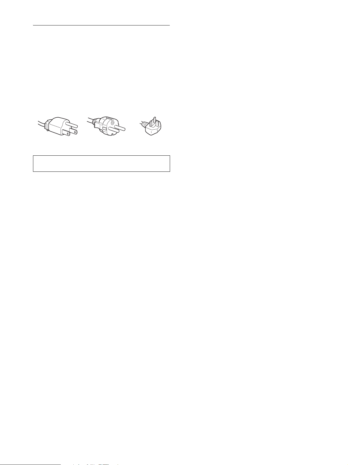
Précautions
Avertissement sur les connexions d’alimentation
• Utilisez le cordon d’alimentation fourni. Si vous utilisez un
cordon d’alimentation différent, assurez-vous qu’il est
compatible avec la tension secteur locale.
Pour les clients aux Etats-Unis
Si vous n’employez pas le cordon approprié, cet l’écran ne sera
pas conforme aux normes FCC obligatoires.
Pour les clients au Royaume-Uni
Si vous utilisez l’écran au Royaume-Uni, veuillez utiliser le
cordon d’alimentation adapté au Royaume-Uni.
Exemples de types de fiches
• Si une image fixe reste affichée pendant une longue durée, il se
peut qu’une image rémanente apparaisse pendant un certain
temps. Cette image rémanente finira par disparaître.
• Le panneau LCD s’échauffe en cours d’utilisation. Il ne s’agit
pas d’un dysfonctionnement.
Remarque sur l’écran à cristaux liquides (LCD Liquid Crystal Display)
Veuillez noter que l’écran LCD est issu d’une
technologie de haute précision. Toutefois, il est
possible que des points noirs ou des points brillants de
lumière (rouge, bleue ou verte) apparaissent
constamment sur l’écran LCD, ainsi que des bandes de
couleurs irrégulières ou une certaine luminosité. Il ne
s’agit pas d’un dysfonctionnement.
(Points effectifs : supérieurs à 99,99%)
pour 100 à 120 V CA pour 200 à 240 V CA pour 240 V CA
L’appareil doit être installé à proximité d’une prise de courant
aisément accessible.
uniquement
Installation
N’installez pas et ne laissez pas l’écran :
• A des endroits exposés à des températures extrêmes, par
exemple à proximité d’un radiateur, d’un conduit de chauffage
ou le rayonnement direct du soleil. L’exposition de l’écran à
des températures extrêmes, comme dans l’habitacle d’une
voiture garée en plein soleil ou à proximité d’un conduit de
chauffage, risque d’entraîner des déformations du châssis ou
des dysfonctionnements.
• A des endroits soumis à des vibrations mécaniques ou à des
chocs.
• A proximité d’appareils générant de puissants champs
magnétiques, comme un téléviseur ou d’autres appareils
électroménagers.
• A des endroit soumis à des quantités inhabituelles de poussière,
de saletés ou de sable, par exemple à côté d’une fenêtre ouverte
ou d’une porte donnant sur l’extérieur. En cas d’installation
temporaire à l’extérieur, veillez à prendre les précautions
requises contre la poussière et les saletés en suspension dans
l’air. Faute de quoi des dommages irréparables risquent de se
produire.
Posez cet appareil sur une surface plane. Ne le placez pas sur une
surface instable, notamment sur le bord d’une table. Si une partie
de l’appareil déborde d’une telle surface, il risque de tomber et de
provoquer des dégâts ou des blessures.
Manipulation de l’écran LCD
• Ne laissez pas l’écran LCD face au soleil, car vous risquez
sinon de l’endommager. Faites donc attention si vous installez
l’écran à côté d’une fenêtre.
• N’appuyez pas sur et veillez à ne pas érafler la surface de
l’écran LCD. Ne posez pas d’objets lourds sur l’écran LCD.
Vous risquez d’altérer l’uniformité de l’écran ou de provoquer
un dysfonctionnement de l’écran LCD.
• Lorsque l’écran est utilisé dans un environnement froid, il est
possible qu’une image rémanente apparaisse sur l’écran. Il ne
s’agit pas d’un dysfonctionnement. L’écran recouvre sa
condition normale dès que la température est revenue à un
niveau normal.
Entretien
• Débranchez le cordon d’alimentation de la prise secteur avant
de procéder au nettoyage de votre écran.
• Nettoyez l’écran LCD avec un chiffon doux. Si vous utilisez un
liquide de nettoyage pour le verre, n’utilisez pas de nettoyant
contenant une solution antistatique ou tout autre additif
similaire, car vous risquez de griffer le revêtement de l’écran
LCD.
• Nettoyez le châssis, le panneau et les commandes à l’aide d’un
chiffon doux légèrement imprégné d’une solution détergente
neutre. N’utilisez aucun type de tampon abrasif, de poudre à
récurer ou de solvant tel que de l’alcool ou de la benzine.
• Ne frottez pas, ne touchez pas et ne tapotez pas la surface de
l’écran avec des objets pointus ou abrasifs comme un stylo à
bille ou un tournevis. Ce type de contact risque de rayer le tube
image.
• Sachez qu’une détérioration des matériaux ou du revêtement de
l’écran LCD risque de se produire si l’écran est exposé à des
solvants volatiles comme des insecticides ou en cas de contact
prolongé avec des objets en caoutchouc ou en vinyle.
Transport
• Débranchez tous les câbles de l’écran et saisissez fermement
celui-ci des deux mains pour le transporter. Si vous laissez
tomber l’écran, vous risquez de vous blesser ou de
l’endommager.
• Pour transporter cet écran en vue de réparations ou de son
expédition, utilisez le carton et les matériaux de
conditionnement originaux.
Installation au mur ou sur un bras
Si vous envisagez d’accrocher l’écran au mur ou de le fixer sur un
bras, consultez un technicien qualifié.
Elimination de l’écran
• N’éliminez pas cet écran avec les ordures
ménagères.
• Le tube fluorescent utilisé dans cet écran contient du
mercure. L’élimination de cet écran doit être
effectuée conformément aux réglementations des
autorités locales compétentes en matière de propreté
publique.
4 (FR)
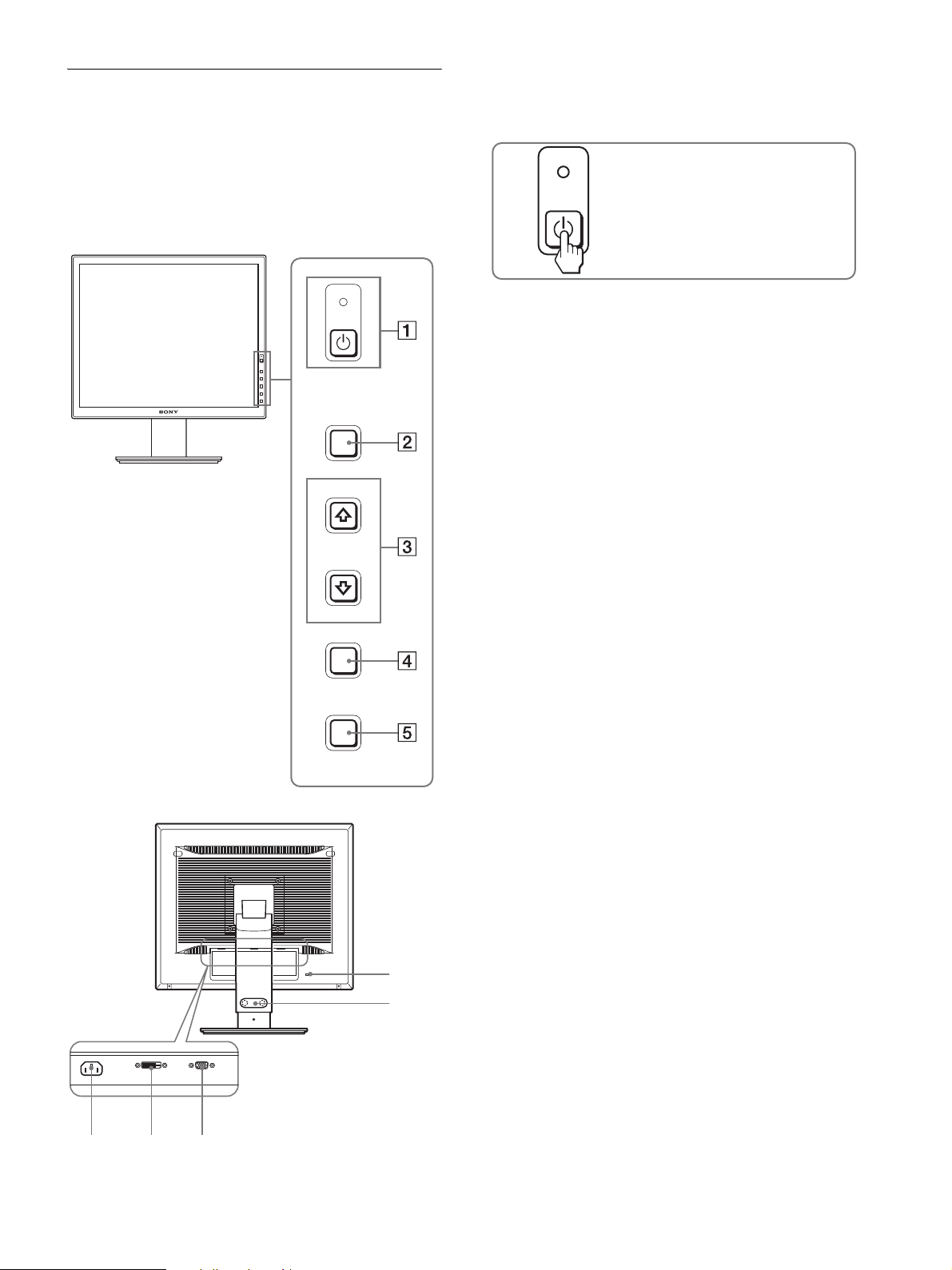
Identification des composants et
des commandes
Pour plus de détails, reportez-vous aux pages indiquées entre
parenthèses.
L’illustration représente uniquement l’un des modèles
disponibles pour cet écran.
1 Commutateur 1 (alimentation) et indicateur
1 (alimentation) (pages 8, 17)
Cet interrupteur met l’écran sous tension. Appuyez de
nouveau sur ce commutateur pour mettre l’écran hors tension.
Avant de l’écran
MENU
INPUT
OK
ECO
Enfoncez le commutateur pour mettre
l’écran sous et hors tension.
2 Touche MENU (pages 10, 11)
Cette touche affiche ou ferme le menu principal.
Vous pouvez également activer la fonction DDC/CI en
maintenant cette touche enfoncée pendant plus de 8 secondes.
3 Touches m/M (page 11)
Ces touches fonctionnent comme touches m/M lorsque vous
sélectionnez des paramètres de menu et que vous effectuez
des réglages.
4 Touche OK (page 11)
Cette touche permet de sélectionner ou de valider des options
dans le menu.
Touche INPUT (page 9) (SDM-S76D/SDM-S96D/
SDM-V76D/SDM-V96D/SDM-S76F/SDM-S96F
uniquement)
Cette touche permet de commuter le signal d’entrée vidéo
entre INPUT1 et INPUT2 lorsque deux ordinateurs sont
raccordés à l’écran.
5 Touche ECO (page 17)
Cette touche permet de réduire la consommation d’énergie.
6 Connecteur AC IN (page 7)
Raccordez le cordon d’alimentation (fourni) à ce connecteur.
Arrière de l’écran
678
0
9
7 Connecteur d’entrée DVI-D (RVB numérique) pour
INPUT1 (page 7) (SDM-S76D/SDM-S96D/SDM-V76D/
SDM-V96D/SDM-S76F/SDM-S96F uniquement)
Ce connecteur transmet des signaux vidéo RVB numériques
conformes à la DVI Rév.1.0.
8 Connecteur d’entrée HD15 (RVB analogique)
(page 7)
Ce connecteur transmet des signaux vidéo RVB analogiques
(0,7 Vp-p, positifs) et des signaux de synchronisation.
9 Support de câble (page 8) (SDM-S76F/SDM-S96F
uniquement)
Cette pièce permet de maintenir les câbles et les cordons
contre l’écran
0 Trou de verrou de sécurité
Le verrou de sécurité doit être utilisé avec le système
Kensington Micro Saver Security System.
Micro Saver Security System est une marque commerciale de
Kensington.
5 (FR)
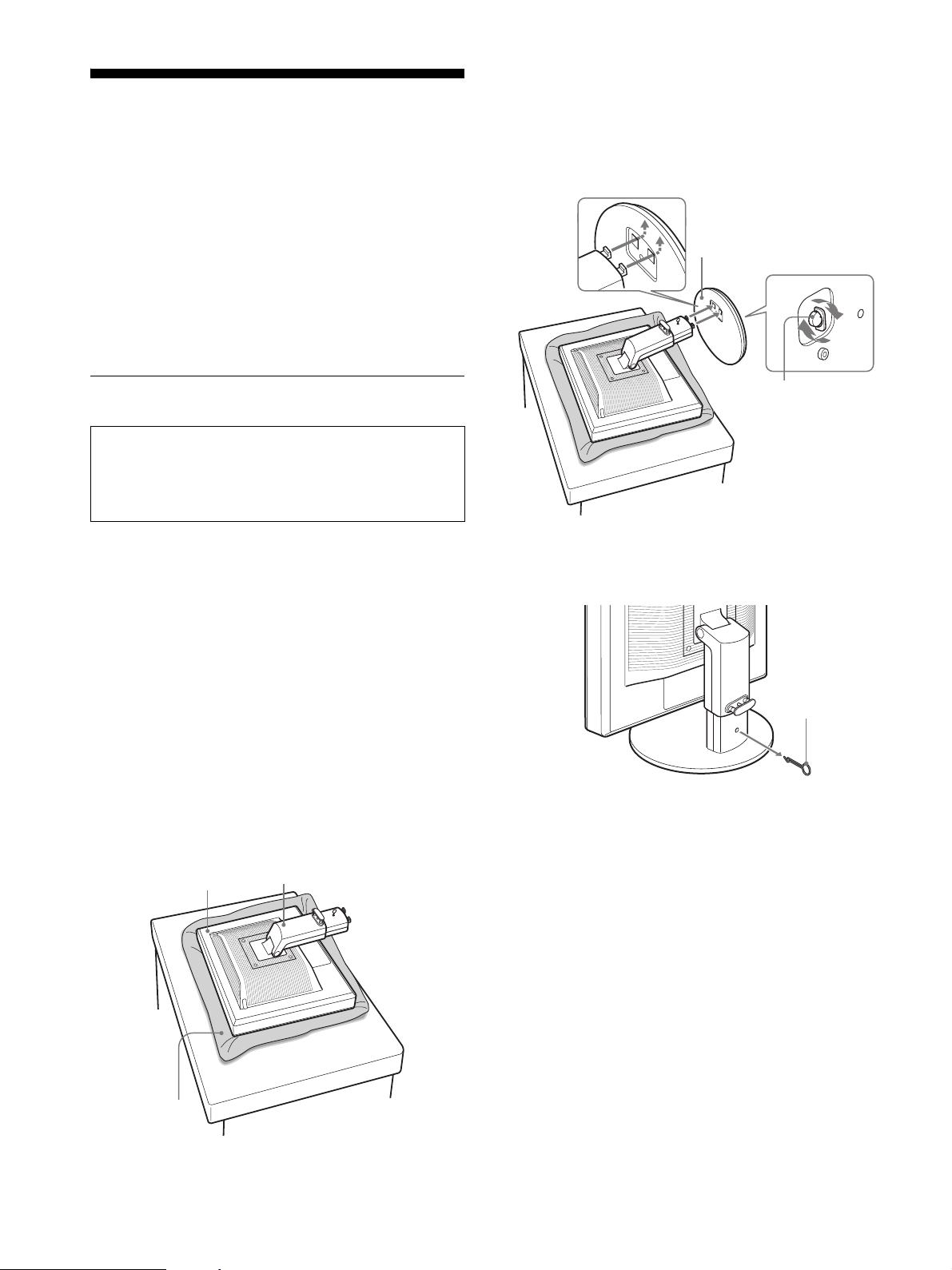
Installation
Avant d’utiliser votre écran, vérifiez si les accessoires suivants se
trouvent bien dans le carton d’emballage :
•Ecran LCD
• Cordon d’alimentation
• Base du support
• Câble de signal vidéo HD15-HD15 (RVB analogique)
• Câble de signal vidéo DVI-D (RVB numérique)
(SDM-S76D/SDM-S96D/SDM-V76D/SDM-V96D/
SDM-S76F/SDM-S96F uniquement)
• CD-ROM (logiciel utilitaire pour Windows et Macintosh,
mode d’emploi, etc.)
• Carte de garantie
• Guide de configuration rapide
5 Encliquetez les parties en saillie du bras du support
sur les orifices de la base du support afin de fixer
cette dernière.
Soulevez la poignée de la vis pour visser
correctement la base du support.
Assurez-vous que la vis est serrée et retournez la
poignée de la vis.
1
2
1 Base du support
Etape 1 : Assemblez le support
N’appuyez pas sur l’ecran LCD lorsque vous placez ou
soulevez l’ecran proprement dit sur un bureau ou une
surface similaire.
Cela peut endommager l’ecran LCD ou affecter son
uniformite.
x En cas d’utilisation du support fourni-
Support fixe
1 Ouvrez le carton et retirez la base du support.
2 Vérifiez les pièces fournies.
• Base du support (avec vis sur le dessous)
3 Posez un tapis souple ou équivalent sur une surface
plane, un bureau par exemple.
Vous risquez d’endommager l’écran LCD et l’écran
proprement dit si vous le déposez directement sur le bureau.
4 Retirez l’écran du carton et posez le cadre de l’écran
le long du bord du bureau.
La figure illustre le support à hauteur réglable. Si vous utilisez
le support fixe, vous arrivez au terme de la procédure dès que
vous avez terminé l’étape 5.
Écran
Support
2 Vis
6 Si vous utilisez un support à hauteur réglable,
retirez la goupille d’arrêt après avoir levé
verticalement le support à hauteur réglable.
Goupille d’arrêt
Remarque
Ne retirez pas la goupille d’arrêt aussi longtemps que le support
demeure couché. Il risquerait de tomber ou de vous blesser s’il
venait à se détacher de la base de manière impromptue.
Tapis souple ou
équivalent
6 (FR)
 Loading...