

Sony SAVA-D900, SAVA-D900FR, SAVA-D900R, SS-T900 Service manual

SAVA-D900/D900FR/
D900R/SS-T900
SERVICE MANUAL
(Photo : SAVA-D900FR)
(Photo : SAVA-D900)
(Photo : SS-T900)
This set is composed of the following table.
Front Speaker SAVA-D900FR
Center/Rear Speaker SS-T900
Woofer Speaker SAVA-D900R
Main Unit SAVA-D900
SPECIFICATIONS
Model Name Using Similar Mechanism NEW
Mechanism T ype CDM53J-DVBU1
Base Unit Type DVBU1
Optical Pick-up Type KHM-220AAA
US Model
(Photo : SAVA-D900R)
— Continued on next page —
DVD HOME THEATER
ACTIVE SPEAKER SYSTEM
SAFETY CHECK-OUT
After correcting the original service problem, perform the following
safety checks before releasing the set to the customer:
Check the antenna terminals, metal trim, “metallized” knobs, screws,
and all other exposed metal parts for A C leakag e. Check leakage as
described below.
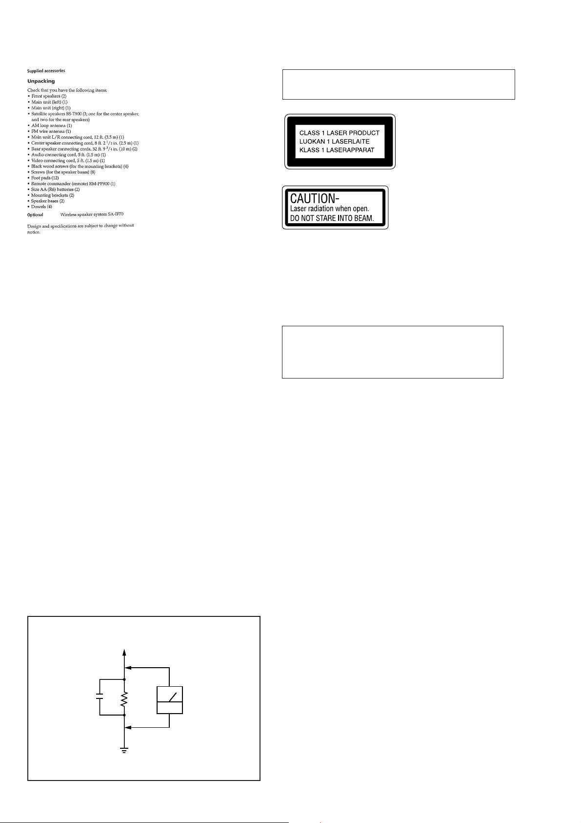
Laser component in this product is capable of emitting radiation
exceeding the limit for Class 1.
This appliance is classified as
a CLASS 1 LASER product.
The CLASS 1 LASER
PRODUCT MARKING is
located on the rear exterior.
This caution
label is located
inside the unit.
CAUTION
Use of controls or adjustments or performance of procedures
other than those specified herein may result in hazardous
radiation exposure.
Notes on chip component replacement
• Never reuse a disconnected chip component.
• Notice that the minus side of a tantalum capacitor may be
damaged by heat.
LEAKAGE
The AC leakage from any exposed metal part to earth Ground and
from all exposed metal parts to any exposed metal part having a
return to chassis, must not exceed 0.5 mA (500 microampers).
Leakage current can be measured by any one of three methods.
1. A commercial leakage tester, such as the Simpson 229 or RCA
WT -540A. Follo w the manufacturers’ instructions to use these
instruments.
2. A battery-operated AC milliammeter. The Data Precision 245
digital multimeter is suitable for this job.
3. Measuring the voltage drop across a resistor by means of a
VOM or battery-operated AC v oltmeter . The “limit” indication
is 0.75 V, so analog meters must have an accurate low-voltage
scale. The Simpson 250 and Sanwa SH-63Trd ar e examples of
a passive VOM that is suitable. Nearly all battery operated
digital multimeters that have a 2V AC range are suitable. (See
Fig. A)
To Exposed Metal
Parts on Set
0.15µF
Ω
1.5k
Earth Ground
AC
voltmeter
(0.75V)
Fig. A. Using an AC voltmeter to check AC leakage.
Flexible Circuit Board Repairing
• Keep the temperature of soldering iron around 270˚C
during repairing.
• Do not touch the soldering iron on the same conductor of the
circuit board (within 3 times).
• Be careful not to apply force on the conductor when soldering
or unsoldering.
SAFETY-RELATED COMPONENT WARNING !!
COMPONENTS IDENTIFIED BY MARK 0 OR DOTTED LINE
WITH MARK 0 ON THE SCHEMATIC DIAGRAMS AND IN
THE PARTS LIST ARE CRITICAL TO SAFE OPERATION.
REPLACE THESE COMPONENTS WITH SONY PARTS
WHOSE PART NUMBERS APPEAR AS SHOWN IN THIS
MANUAL OR IN SUPPLEMENTS PUBLISHED BY SONY.
2

TABLE OF CONTENTS
1. GENERAL ......................................................................... 4
2. DISASSEMBLY
2-1. Grille Frame (B) Assy ................................................... 6
2-2. Amplifier Assy .............................................................. 6
2-3. Amplifier Chassis .......................................................... 7
2-4. AMP Board ................................................................... 7
2-5. Power Transformer (T900) ............................................ 8
2-6. PS Board........................................................................8
2-7. Mechanism Section .......................................................9
2-8. Video Board................................................................... 9
2-9. Main Board and DVD Board....................................... 10
2-10.Mechanism (CDM53J-DVBU1) ................................. 10
2-11.Base Unit (DVBU1) ....................................................11
2-12.Magnet Assy ................................................................ 11
2-13.Tray (SUB) .................................................................. 12
2-14.Chassis (Mold B), Stocker, Slider (Selection)............. 12
2-15.How to Assemble the Gears ........................................13
2-16.How to Attach the Slider (Selection)........................... 13
2-17.How to Attach the Stocker........................................... 14
2-18.How to Attach the Chassis (Mold B)........................... 14
3. TEST MODE.....................................................................15
4. ELECTRICAL ADJUSTMENT ................................. 26
4-1. Adjustment of Video System ....................................... 26
4-2. Adjustment Related Parts Arrangement ...................... 27
6. EXPLODED VIEWS
6-1. Overall Section ............................................................ 72
6-2. Main Unit (SAVA-D900) Section................................73
6-3. Main Chassis Section ..................................................74
6-4. Amplifier Chassis Section ........................................... 75
6-5. Mechanism Section-1 (CDM53J-DVBU1) ................. 76
6-6. Mechanism Section-2 (CDM53J-DVBU1) ................. 77
6-7. Woofer Speaker (SAVA-D900R) Section .................... 78
6-8. Front Speaker (SAVA-D900FR) Section ..................... 79
6-9. Center/Rear Speaker (SS-T900) Section ..................... 80
7. ELECTRICAL PARTS LIST.................................81
5. DIAGRAMS
5-1. Circuit Boards Location ..............................................28
5-2. Block Diagrams ........................................................... 30
– DVD Section – .........................................................30
– Main Section – ......................................................... 31
5-3. Printed Wiring Board – DVD Section – ...................... 32
5-4. Schematic Diagram – DVD (1/12) Section – .............. 34
5-5. Schematic Diagram – DVD (2/12) Section – .............. 35
5-6. Schematic Diagram – DVD (3/12) Section – .............. 36
5-7. Schematic Diagram – DVD (4/12) Section – .............. 37
5-8. Schematic Diagram – DVD (5/12) Section – .............. 38
5-9. Schematic Diagram – DVD (6/12) Section – .............. 39
5-10.Schematic Diagram – DVD (7/12) Section – .............. 40
5-11.Schematic Diagram – DVD (8/12) Section – .............. 41
5-12.Schematic Diagram – DVD (9/12) Section – .............. 42
5-13.Schematic Diagram – DVD (10/12) Section – ............ 43
5-14.Schematic Diagram – DVD (11/12) Section – ............ 44
5-15.Schematic Diagram – DVD (12/12) Section – ............ 45
5-16.Printed Wiring Board – TK Section – ......................... 46
5-17.Schematic Diagram – TK Section – ............................ 47
5-18. Schematic Diagram – MAIN Section – ...................... 48
5-19. Printed Wiring Board – MAIN Section – ................... 49
5-20. Schematic Diagram – AMP Section – ........................ 50
5-21. Printed Wiring Board – AMP Section –...................... 51
5-22. Schematic Diagram – VIDEO Section –..................... 52
5-23.Printed Wiring Board – VIDEO Section – .................. 53
5-24.Schematic Diagram – DISPLAY Section – ................. 54
5-25.Printed Wiring Board – DISPLAY Section – .............. 55
5-26.Schematic Diagram – MOTOR Section – ................... 56
5-27.Printed Wiring Board – MOTOR Section – ................ 57
5-28.Printed Wiring Board – PS Section – .......................... 58
5-29.Schematic Diagram – PS (1/2) Section – ....................60
5-30.Schematic Diagram – PS (2/2) Section – ...................61
5-31.Printed Wiring Board – POWER Section –................. 62
5-32.IC Pin Functions .......................................................... 63
5-33.IC Block Diagrams ...................................................... 67
NOTES ON HANDLING THE OPTICAL PICK-UP BLOCK
OR BASE UNIT
The laser diode in the optical pick-up block may suffer electrostatic
break-down because of the potential difference generated by the
charged electrostatic load, etc. on clothing and the human body.
During repair, pay attention to electrostatic break-down and also
use the procedure in the printed matter which is included in the
repair parts.
The flexible board is easily damaged and should be handled with
care.
NOTES ON LASER DIODE EMISSION CHECK
The laser beam on this model is concentrated so as to be focused on
the disc reflective surface by the objective lens in the optical pickup block. Therefore, when checking the laser diode emission,
observe from more than 30 cm away from the objective lens.
LASER DIODE AND FOCUS SEARCH OPERATION
CHECK
Carry out the “S curve check” in “CD section adjustment” and check
that the S curve waveform is output several times.
3

SECTION 1
GENERAL
This section is extracted
from instruction manual.
4
5
SECTION 2
n
DISASSEMBLY
Note: Follow the disassembly procedure in the numerical order given.
SAVA-D900 (MAIN UNIT)
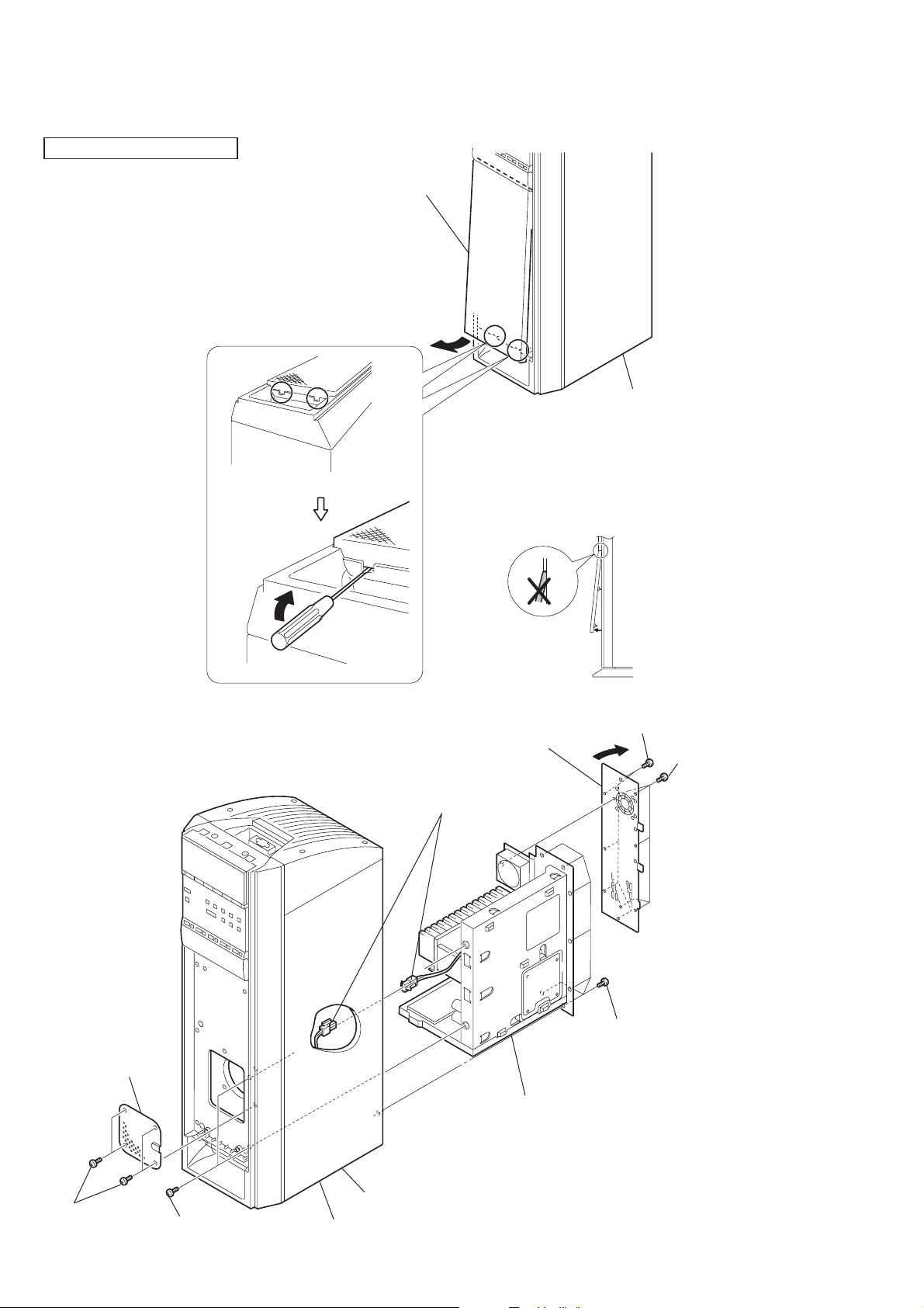
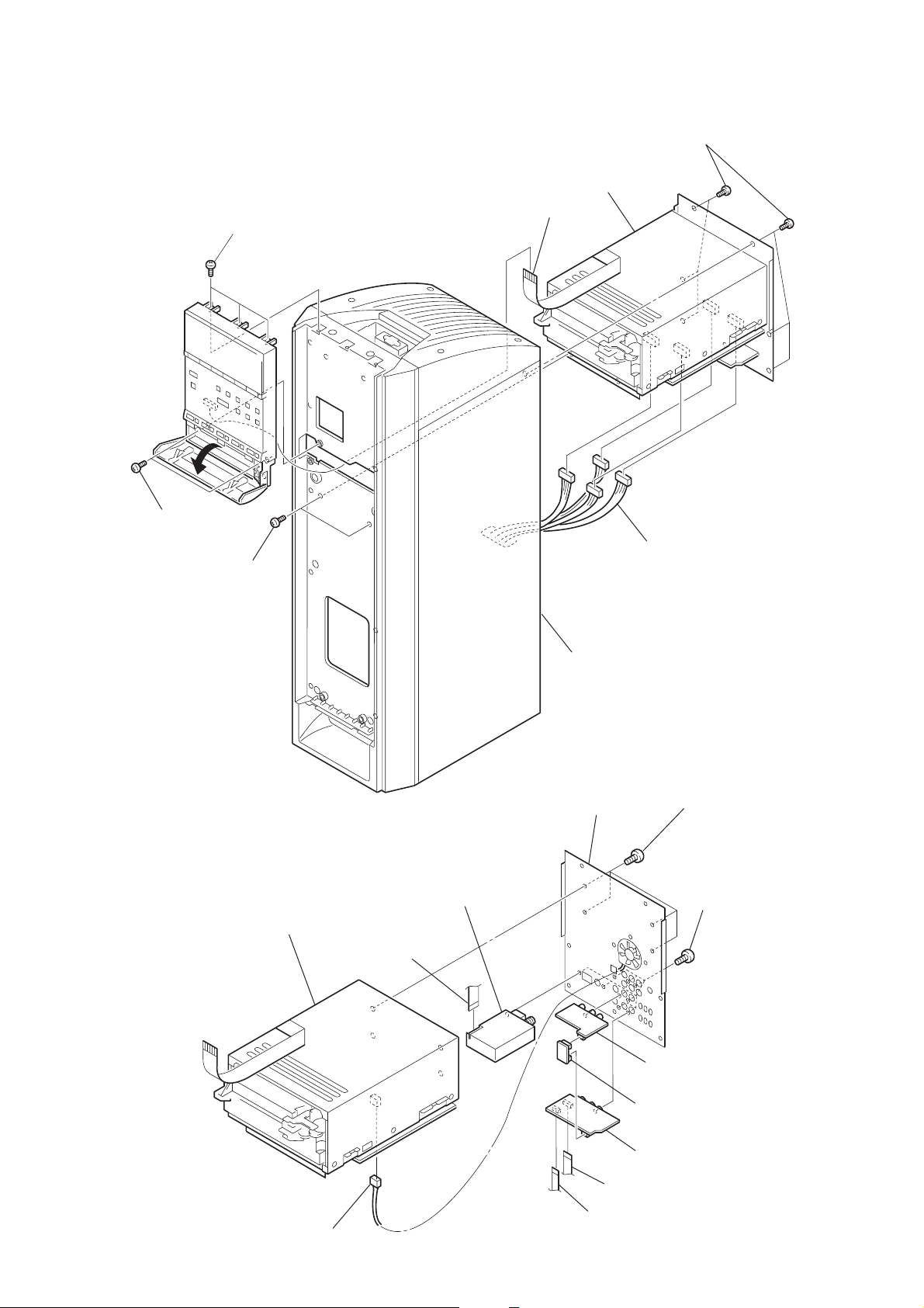
2-1. GRILLE FRAME (B) ASSY
2
Grille frame (B) assy
1
Note : Be careful not to open
1
excessively as shown.
Main unit (L-ch) sectio
2-2. AMPLIFIER ASSY
2
Cover (BF)
FOR AMP ASSY
4
Five screws
(BVTT4
×
6
Back panel (L/B)
8
Connecter
FOR
9
Amplifier assy
7
20)
5
Five screws
(BVTP3
Seven screws
(BVTP4
×
20)
×
8)
6
1
Four screws
(P4
×
12)
3 Two screws
(BVTT4
×
25)
Main unit (L-ch) section
Main unit (L-ch) section
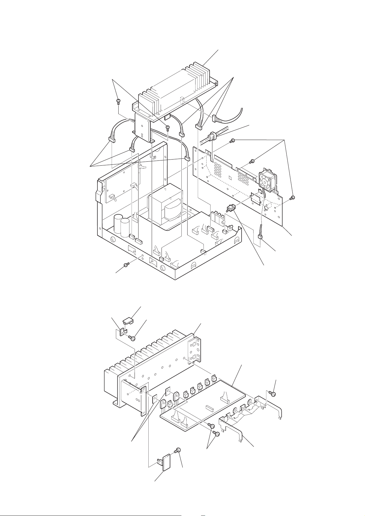
2-3. AMPLIFIER CHASSIS
7
Two screws
(transistor)
5
Connecters
0
Heatsink and AMP board
4
Connecters
3
Cord bushing
8
Twelve screws
(BVTP3
×
8)
2-4. AMP BOARD
6
Screw (BVTP3 × 8)
8
Bracket
9
THERMO board
7
Screw
(BVTP3
9
Back panel (L/A)
1
Connecter
2
Connecter
0
×
8)
Heatsink
4
AMP board
1
Six screws
(BVTP3
×
8)
Supplied with
Q1704, 1705
6
REG board
5
Screw
(BVTP3
3
Three screws
(transistor)
×
8)
2
Bracket
7

)
2-5. POWER TRANSFORMER (T900)
1
Connector
3
Four screws
(BVTT4
×
8)
4
Power transformer (T900
2
Connectors
2-6. PS BOARD
5
STBY board
4
Four screws
(BVTP3 × 8)
2 Six
(BVTP3 × 8)
1
Connector
screws
3
PS board
8
)
2-7. MECHANISM SECTION
1
3 screws
2
2 screws
(BVTP3
3
(BVTT4
(BVTP3
×
12)
2 screws
×
×
25)
12)
6
Flat wire
7
Mechanism section
4
Six screws
(BVTT4
5
Four connectors
×
20)
2-8. VIDEO BOARD
4
DVD section
5
Flat wire
6
TUNER unit
Main unit (L-ch) section
qs
Panel (L/C) back
2
Four screws
(BVTP3
3
0
Video board
9
V-connect board
×
8)
Nine screws
(BVTP3
×
8
1
Connector
8
7
Flat wire
qa
S-video board
Flat wire
9

2-9. MAIN BOARD AND DVD BOARD
e
)
qf
DVD assy
7
6
qd
DVD board
Four screws
MAIN board
(BVTP3
2
Flat wire
×
8)
3
Flat wire
qs
Four screws (BVTP3 × 8)
qa
0
Connector
9
Flat wire
8
Bracket
5
Four screws
(BVTP3
Flat wire
4
Flat wir
×
8)
2-10. MECHANISM (CDM53J-DVBU1)
4
Two screws
(BVTP3 × 8)
5
Mechanism
(CDM53J-DVBU1)
3
Cover
1
Flat wire
1
Ten screws (BVTP3 × 8)
2
Four screws
(BVTP3 × 8
10
6
Chassis
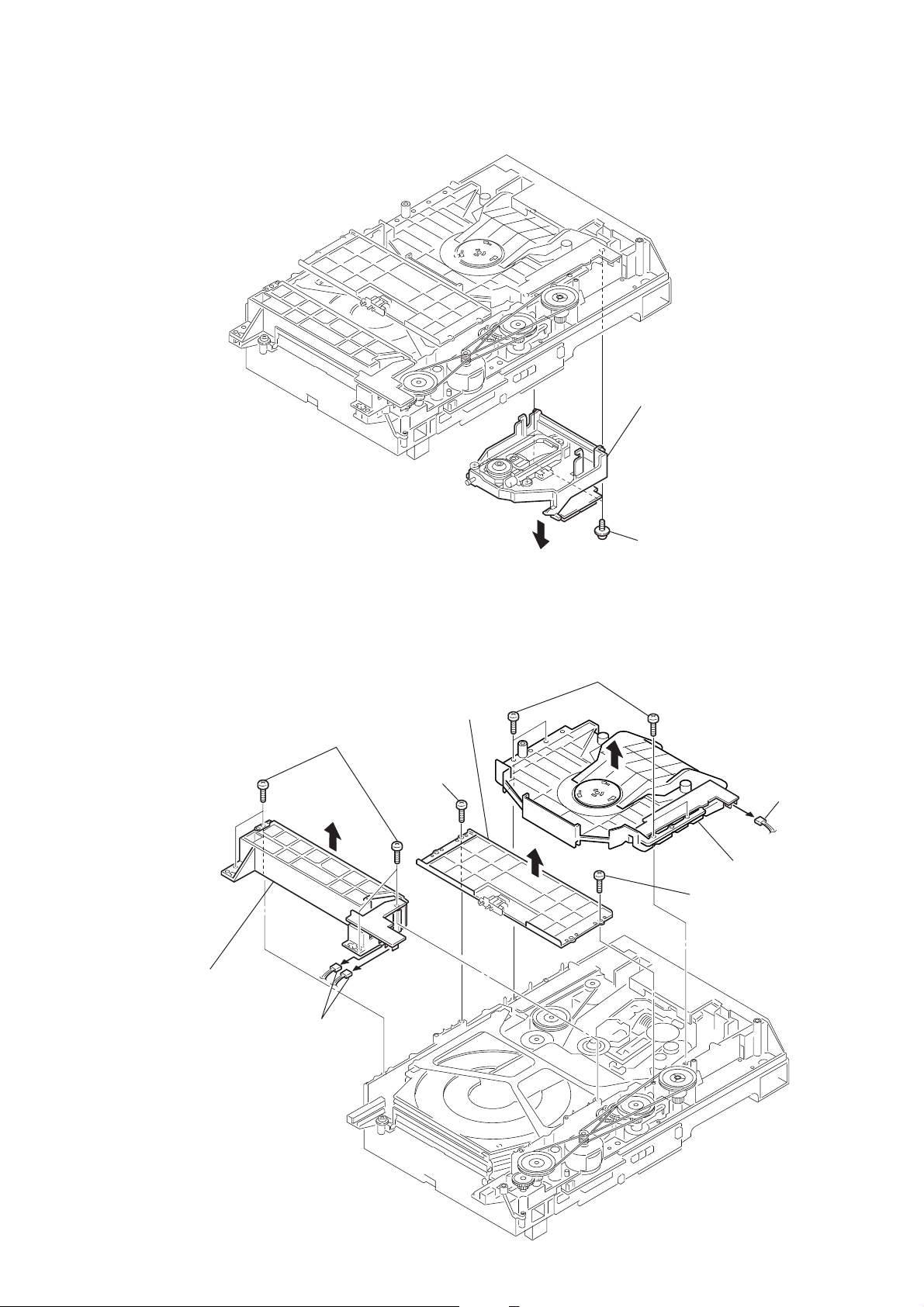
2-11. BASE UNIT (DVBU1)
r
2
Base unit (DVBU1)
1
Two screws
(PTPWH M2.6)
2-12. MAGNET ASSY
3
Fitting base
(guide) assy
2
Four screws
(BVTP M2.6)
1
Two connectors
(CN709, 715)
6
Bracket
(chassis)
4
Screw
(BVTP M2.6)
8
Four screws
(BVTP M2.6)
5
(BVTP M2.6)
Screw
7
Connecto
(CN710)
9
Magnet assy
11
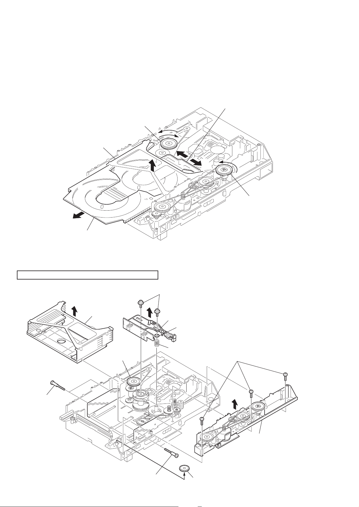
2-13. TRAY (SUB)
)
1 Turn the pulley (LD) and move the slider (selection) in the
direction of the arrow L.
2 Turn the pulley (mode) in the direction of the arrow to adjust
the tray (sub) that you want to remove.
(It depends on the height and position
of the stocker.)
3 Turn the pulley (LD) and move the slider
(selection) in the direction of the arrow R.
4 Turn the pulley (mode) in the direction of the arrow so
that you can remove the tray (sub) that you
want to remove.
Pully (LD)
Slider (selection)
Stocker section
Tray (sub)
L
2-14. CHASSIS (MOLD B), STOCKER, SLIDER (SELECTION)
Note: When assembling the parts, refer to pages 13 and 14.
7
Two screws
(PTPWH M2.6)
6
Stocker
section
8
Slider (selection)
9
Washer
R
Pully (mode)
12
5
Two step
screws
Pully (LD)
4
Two step screws
0
Compression
spring
3
Gear (eject)
1
Three screws
(BVTP M2.6)
2
Note: Rotating the pully (LD),
shift the slider (selection
to the left.
Chassis (mold B) section

2-15. HOW TO ASSEMBLE THE GEARS
3
Gear (gear B)
Portion A
Adjust the gear (gear B) with the
portion A as shown.
1
Slide the slider (u/d)
fully in the arrow
direction.
2
Gear (U/D slider)
Slider (U/D) gear
4
Gear (gear A)
Gear
(gear B)
Linearly
Adjust the gear so that it meshes with
the bottom tooth of slider (U/D) gear,
as shown.
2-16. HOW TO ATTACH THE SLIDER (SELECTION)
2
Gear (chuking)
Rotary encoder
Align with the slot of
rotary encoder.
6
Two screws
(PTPWH M2.6)
5
Washer
4
Compression spring
7
Insert the slider (selection)
into the portion A.
Adjust so as to be aligned with
gear B linearly, as shown.
Portion A
1
Rotary encoder
Align marking
3
Convex portion of
slider (selection)
Gear (chuking)
Insert a convex portion into
a groove of gear (chuking).
13

2-17. HOW TO ATTACH THE STOCKER
1
Stocker section
2
Portion A of tray (sub)
Hook the portion A of tray (sub)
to the slider (selection).
3
Two step screws
2-18. HOW TO ATTACH THE CHASSIS (MOLD B)
3
Three screws
(BVTP M2.6)
Portion A
of tray (sub)
4
Two step screws
Sticking of
slider (selection)
14
2
Insert the gear (eject0
under the gear (LD
deceleration).
Gear (LD deceleration)
Portion A
Portion B of
slider (selection)
1
Insert the portion A of
chassis (mold B) section
into the portion B of
slider (selection).

SECTION 3
TEST MODE
How to enter the test mode
Blue display (test mode)
DVD microprocessor downloading mode
All cliar of STR side
Key Check
Display Check
Speaker Check
* The speaker check mode is the test mode in which the sound signel that is input to the TV INPUT is output
from all speakers at the unity sound level.
• Selcting 9K or 10K of AM
Select the AM band. Turn off the main power . While pressing the SUB WOOFFER MODE button, press the ?/1
(power) switch to turn on the main power.
Order of pressing simultaneously
123
SWMODE
SWMODE
SWMODE
SWMODE
SWMODE
SWMODE
BAND
STOP
STOP
STOP
BAND
STOP
DISC 1
DISC 2
DISC 3
EJECT 3
EJECT 5
EJECT 4
Press to return
—
—
—
SAVA-D900’s key
STOP
STOP
15

3-1. GENERAL DESCRIPTION
The T est Mode allows you to make dia gnosis and adjustment easily
using the remote commander and monitor TV. The instructions,
diagnostic results, etc. are given on the on-screen display (OSD).
3-2. STARTING TEST MODE
Set the FUNCTION to DVD with the main unit power on. Next,
while pushing the [STOP] button and the [MUTING] button on the
main unit at the same time, turn the regulator to the right to start
T est Mode and display the menu shown belo w on the TV screen. At
the bottom of the menu screen, the model name and revision number
are displayed.
To execute each function, select the desired menu and press its
number on the remote commander. To exit from Test Mode, press
the [POWER] button.
Test Mode Menu
0. Syscon Diagnosis
1. Drive Auto Adjustment
2. Drive Manual Operation
3. Mecha Aging
4. Emergency History
5. Version Information
6. Video Level Adjustment
Exit: Power Key
_
Model : HCX932xxxx
Revision: 1.xxx
3-3. SYSCON DIAGNOSIS
The same contents as board detail check by serial interface can be
checked from the remote commander.
On the Test Mode Menu screen, press
commander, and the following check menu will be displayed.
### Syscon Diagnosis ###
Check Menu
0. Quit
1. All
2. Version
3. Peripheral
4. Servo
5. Supply
6. AV Decoder
7. Video
8. Audio
_
0. Quit
Quit the Syscon Diagnosis and return to the Test Mode Menu.
1. All
All items continuous check
This menu checks all diagnostic items continuously. Normally, all
items are checked successively one after another automatically
unless an error is found, but at a certain item that requires judgment
through a visual check to the result, the following screen is displayed
for the key entry.
[0] key on the remote
### Syscon Diagnosis ###
Diag All Check
No. 2 Version
2-3. ROM Check Sum
Check Sum = 2005
Press NEXT Key to Continue
Press PREV Key to Repeat
_
For the ROM Check, the check sum calculated by the Syscon is
output, and therefore you must compare it with the specified value
for confirmation.
Following the message, press [NEXT] key to go to the ne xt item, or
[PREV] key to repeat the same check again. To quit the diagnosis
and return to the Check Menu screen, press [STOP] or
[ENTER] key. If an error occurred, the diagnosis is suspended and
the error code is displayed as shown below.
### Syscon Diagnosis ###
3-3. EEPROM Check
Error 03: EEPROM Write/Reed N
Address : 00000001
Write Data : 2492
Read Data : 2490
Press NEXT Key to Continue
Press PREV Key to Repeat
_
Press [STOP] key to quit the diagnosis, or [PREV] key to repeat
the same item where an error occurred, or [NEXT] key to continue
the check from the item next to faulty item.
Selecting 2 and subsequent items calls the submenu screen of each
item.
For example, if “5. Supply” is selected, the following submenu will
be displayed.
### Syscon Diagnosis ###
Check Menu
No. 5 Supply
0. Quit
1. All
2. ARP Register Check
3. ARP to RAM Data Bus
4. ARP to RAM Address Bus
5. ARP RAM Check
_
0. Quit
Quit the submenu and return to the main menu.
1. All
All submenu items continuous check
This menu checks 2 and subsequent items successively . At the item
where visual check is required for judgment or an error occurred,
the checking is suspended and the message is output for key entry.
Normally, all items are checked successively one after another
automatically unless an error is found.
16

Selecting 2 and subsequent items executes respective menus and
outputs the results.
For the contents of each submenu, see “Check Items List”.
General Description of Checking Method
2. Version
(2-2) Revision
ROM revision number is displayed.Error: Not detected.
The revision number defined in the source file of ROM (At
the beginning of mass production, the Flash ROM of IC205
is used, but midway it is replaced by the IC206 OTP ROM.
IC205 or IC206) is displayed with four digits.
Below IC205 are all IC205 or IC206.
(2-3) ROM Check Sum
Check sum is calculated.
Error: Not detected.
The 8-bit data are added at addresses 0x000F0000 ~
0x002EFFFF of ROM (IC205) and the result is displayed
with 4-digit hexadecimal number. Error is not detected.
Compare the result with the specified value.
4. Servo
(4-2) Servo DSP Check
Data write → read, and accord check
Error 12: Read data discord
Data 0x9249, 0x2942, 0x4294 are written to the address
0x602 of RAM in the Servo DSP (IC701), then read and
checked.
(4-3) DSP Driver Test
Test signal data → DSP Driver
Error: Not detected.
Caution: Do not conduct this test with a mechanical deck
connected.
The maximum voltage is applied to the Servo Driver IC
(IC801, IC802). If mechanical deck is connected, the motor and optics could be damaged. Disconnect mechanical
deck following the output message, then enter specified 4or 5-digit number from the remote commander, and press
the [ENTER]. The test is conducted only when the input
data accord. Check the output level, then press the [NEXT]
to finish the test.
This test is skipped if “All” is selected.
(2-4) Model Type
Model code is displayed.
Error: Not detected.
The model code read from EEPROM (IC201) is displayed
with 2-digit hexadecimal number.
Model Type
SAVA-D900 20
(2-5) Region
Region code is displayed.
Error: Not detected.
The region code determined from the model code is displayed.
3. Peripheral
(3-2) Gate Array Check
Data write → read, and accord check
Error 02: Gate array write/read discord
Data 0x00~0xFF are written to the address 0xF of GA
(IC601), then read and checked if they accord.
(3-3) EEPROM Check
Data write → read, and accord check
Error 03: EEPROM write/read discord
Data 0x9249, 0x2942, 0x4294 are written to addresses
0x00~0xFF of EEPROM (IC201), then read and checked.
Before writing, the data are saved, then after checking, they
are written to restore the contents of EEPROM.
Supplement: How to disconnect mechanical deck
Disconnect flat cables connected to the CN002 and CN003
of MB-82/85 board. Also, disconnect harness from the
CN011.
5. Supply
Caution: Do not conduct this check with a mechanical deck
connected.
An access is made to the stream supply and servo control
IC (IC303) and external RAM (IC304) using check data.
If mechanical deck is connected, the motor and optics
could be damaged. This check is also executed by the “ All”
menu item.
Supplement: How to disconnect mechanical deck
Disconnect flat cables connected to the CN002 and
CN003 of DVD board. Also, disconnect harness from
the CN011.
(5-2) ARP Register Check
Data write → read, and accord check
Error 08: ARP register write, and read data discord
Data 0x00 to 0xFF are written to the TMAX register (address 0xC6) in ARP (IC303), then the y are read and checked.
(5-3) ARP to RAM Data Bus
Data write → read, and accord check
Error 09: ARP ←→ RAM data bus error
Data 0x0001 to 0x8000 where one bit each is set to 1 are
written to the address 0 of RAM (IC304) connected to the
ARP (IC303) through the bus, then they are read and
checked. In case of discord, written bit pattern and read
data are displayed. If data where multiple bits are 1 are
read, the bits concerned may touch each other. Further, if
data where certain bit is always 1 or 0 regardless of written
data, the line could be disconnected or shorted.
17

(5-4) ARP to RAM Address Bus
Data write → other address read discord check
Error 10: ARP → RAM address bus error
Caution: Address and data display in case of an error is
different from the display of other diagnosis (de-
scribed later).
Before starting the test, all addresses of RAM (IC304) are
cleared to 0x0000.
First, 0xA55A is written to the address 0x00000, and the
address data are read and checked from addresses 0x00001
to 0x80000 while shifting 1 bit each. Next, the data at that
address is cleared, and it is written to the address 0x00001,
and read and checked in the same manner. This check is
repeated up to the address 0x80000 while shifting the address data by 1 bit each.
If data other than 0 is read at the addresses except written
address, an error is given because all addresses were already cleared to 0. In this check, the error display pattern is
different from that of other diagnosis; read data, written
address, and read address are displayed in this order. Ho wever , the message uses same template, and accordingly exchange Address and Data when reading. The following display, for example,
6. AV Decoder
(6-2) 1930 RAM
Data write → read, and accord check
Error 13: AVD RAM read data discord
The program code data stored in ROM (IC205) are copied
to all areas of RAM (IC402, IC403) connected to the AVD
(IC401) through the bus, then they are read and checked if
they accord. Further, the same test is conducted once again
with the data where all bits are inverted between 1 and 0. If
discord is detected, faulty address, written data, and read
data are displayed following the error code 13, and the test
is suspended.
(6-3) 1930 SP
ROM → AVD RAM → Video OUT
Error: Not detected.
The data including sub picture streams in ROM (IC205)
are transferred to the RAM (IC402, IC403) in AVD (IC401),
and output as video signals from the AVD (IC401).
They are output from all video terminals (Composite, Y/C).
7. Video
### Syscon Diagnosis ###
5-4. ARP to RAM Address Bus
Error 10: ARP - RAM Address B
Address : 0000A55A
Write Data : 00000000
Read Data : 00080000
Press NEXT Key to Continue
Press PREV Key to Repeat
_
shows the data 0xA55A was read from address 0x00080000
though it was written to the address 0x00000000. This implies that these addresses are in the form of shadow. Also,
if the read data is not 0xA55A, another error will be present.
(5-5) ARP RAM Check
Data write → read, and accord check
Error 11: ARP RAM read data discord
The program code data stored in ROM are copied to all
areas of RAM (IC304) connected to the ARP (IC303)
through the bus, then they are read and checked if they accord. If the detail check was selected initially, the data are
written to all areas and read, then the same test is conducted
once again with the data where all bits are inverted between
1 and 0. If discord is detected, faulty address, written data,
and read data are displayed following the error code 11,
and the test is suspended.
(7-2) Color Bar
AVD color bar command write → Video OUT
Error: Not detected.
The command is transferred to the AVD, and the color bar
signals are output from video terminals.
They are output from all video terminals (Composite, Y/C).
8. Audio
(8-2) ARP → 1930
Error 14 : ARP → 1930 video NG
15 : ARP → 1930 audio NG
18

Check Items List
2) Version
(2-2) Revision
(2-3) ROM Check Sum
(2-4) Model Type
(2-5) Region
3) Peripheral
(3-2) Gate Array Check
(3-3) EEPROM Check
4) Servo
(4-2) Servo DSP Check
(4-3) DSP Driver Test
5) Supply
(5-2) ARP Register Check
(5-3) ARP to RAM Data Bus
(5-4) ARP to RAM Address Bus
(5-5) ARP RAM Check
6) AV Decoder
(6-2) 1930 RAM
(6-3) 1930 SP
7) Video
(7-2) Color Bar
Error Codes List
00: Error not detected
01: RAM write/read data discord
02: Gate array NG
03: EEPROM NG
08: ARP register read data discord
09: ARP ←→ RAM data bus error
10: ARP ←→ RAM address bus error
11: ARP RAM read data discord
12: Servo DSP NG
13: 1930 SDRAM NG
14: ARP → 1930 video NG
15: ARP → 1930 audio NG
16: 1910 UCODE download NG
17: System call error (function not supported)
18: System call error (parameter error)
19: System call error (illegal ID number)
20: System call error (time out)
90: Error occurred
91: User verification NG
92: Diagnosis cancelled
8) Audio
(8-2) ARP → 1930
(8-3) Test Tone
19

3-4. DRIVE AUTO ADJUSTMENT
On the Test Mode Menu screen, press [1] key on the remote
commander, and the dri ve auto adjustment menu will be displayed.
## Drive Auto Adjustment ##
Adjustment Menu
0. ALL
1. DVD-SL
2. CD
3. DVD-DL
4. SACD
Exit: RETURN
Normally, [0] is selected to adjust DVD (single layer), CD, DVD
(dual layer), and SACD in this order. But, individual items can be
adjusted for the case where adjustment is suspended due to an error.
In this mode, the adjustment can be made easily through the
operation following the message displayed on the screen.
The disc used for adjustment must be the one specified for
adjustment. However, for SACD disc, use the player with initial
data if the disc is not available.
0. ALL
Select [0] and press [ENTER] key, and the servo set data in
EEPROM will be initialized. Then, 1. D VD-SL disc, 2. CD disc , 3.
DVD-DL disc, and 4. SACD disc are adjusted in this order. Each
time one disc was adjusted, it is ejected. Replace it with the specified
disc following the message. Though the message to confirm whether
discs other than SACD disc are adjusted is not displayed, you can
finish the adjustment if pressing the
adjustment of each disc, the measurement for disc type judgment is
made. As automatic adjustment does not judge the disc type unlik e
conventional models, take care not to insert wrong type discs. Also,
do not give a shock during adjustment.
[STOP] button. During
1. DVD-SL (single layer)
Select
[1], insert DVD single layer disc, and press [ENTER] key,
and the adjustment will be made through the following steps, then
adjusted values will be written to the EEPROM.
DVD Single Layer Disc Adjustment Steps
1. SLED TILT Reset
2. Disc Check Memory SL
3. Wait 300 msec
4. Set Disc Type SL
5. LD ON
6. Spdl Start
7. Wait 1 sec
8. Focus Servo ON 0
9. Auto Track Offset Adjust
10. CLVA ON
11. Wait 500 msec
12. Tracking ON
13. Wait 1 sec
14. Sled ON
15. Check CLV Lock
16. Auto LFO Adjust
17. Auto Focus Offset Adjust
18. Auto Tilt Position Adjust
19. Auto Focus Gain Adjust
20. Auto Focus Offset Adjust
21. EQ Boost Adjust
22. Auto LFO Adjust
23. Auto Track Gain Adjust, Search Check
24. 32Tj Fwd
25. 32Tj Rev
26. 500Tj Fwd
27. 500Tj Rev
28. All Servo Stop
29. Eep Copy Loop Filter Offset
20

2. CD
3. DVD-DL (dual layer)
Select [2], insert CD disc, and press [ENTER] key, and the
adjustment will be made through the following steps, then adjusted
values will be written to the EEPROM.
CD Adjustment Steps
1. Sled Tilt Rest
2. Disc Check Memory CD
3. Wait 500 msec
4. Set Disc Type CD
5. LD ON
6. Spdl Start
7. Wait 500 msec
8. Focus Servo ON 0
9. Auto Track Offset Adjust
10. CLVA ON
11. Wait 500 msec
12. Tracking ON
13. (TC Display Start)
14. Wait 1 sec
15. Jitter Display Start
16. Sled ON
17. Check CLV ON
18. Auto LFO Adjust
19. Auto Focus Offset Adjust
20.
21. Auto Focus Gain Adjust
22. Auto Focus Offset Adjust
23. Eq Boost Adjust
24. Auto LFO Adjust
25. Auto Track Gain Adjust, Search Check
26. 32Tj Fwd
27. 32Tj Rev
28. 500Tj Fwd
29. 500Tj Rev
30. All Servo Stop
Select [3], insert D VD dual layer disc, and press [ENTER] key , and
the adjustment will be made through the following steps, then
adjusted values will be written to the EEPROM.
DVD Dual Layer Disc Adjustment Steps
1. Sled Tilt Reset
2. Disc Check Memory DL
3. Wait 500 msec
4. Set Disc Type DL
5. LD ON
6. Spdl Start
7. Wait 1 sec, Layer 1 Adjust
8. Focus Servo ON 0
9. Auto Track Offset Adjust
10. Clva ON
11. Wait 500 msec
12. Tracking ON
13. Wait 500 msec
14. Sled ON
15. Check CLV Lock
16. Auto Loop Filter Offset Auto Focus Adjust
17.
18. Auto Focus Gain Adjust
19. Auto Focus Offset Adjust
20. Eq Boost Adjust
21. Auto Loop Filter Offset
22. Auto Track Gain Adjust, Search Check
23. 32Tj Fwd
24. 32Tj Rev
25. 500Tj Fwd
26. 500Tj Rev, Layer 0 Adjust
27. Fj (L1 -> L0)
28. Auto Track Offset Adjust L0
29. Clva ON
30. Wait 500 msec
31. Tracking ON
32. Wait 500 msec
33. Sled ON
34. Check CLV Lock
35. Auto Focus Filter Offset
36. Auto Focus Adjust
37.
38. Auto Focus Gain Adjust
39. Auto Focus Offset Adjust
40. Eq Boost Adjust
41. Auto Loop Filter Offset
42. Auto Track Gain Adjust, Search Check
43. 32Tj Fwd
44. 32Tj Rev
45. 500Tj fwd
46. 500Tj Rev, Layer Jump Check
47. Lj (L0 -> L1)
48. Lj (L1 -> L0)
49. All Servo Stop
21

4. SACD
3-5. DRIVE MANUAL OPERATION
Select [4], insert SACD disc, and press [ENTER] key, and the
adjustment will be made through the following steps, then adjusted
values will be written to the EEPROM. However, if SACD disc is
not available, use the player with initial data, skipping the SACD
adjustment. In this case, you can finish the adjustment if pressing
the [STOP] button.
SACD Adjustment Steps
1. Sled Tilt Reset
2. Set Disc Type CD
3. LD ON
4. Spdl Start
5. Wait 500 msec
6. Focus Servo ON 0
7. Auto track Offset Adjust
8.
9. CLVA ON
10. Wait 500 msec
11. Tracking ON
12. Wait 1 sec
13. Sled ON
14. Check CLV ON
15. Auto Focus Offset Adjust
17.
18. Auto Focus Gain Adjust
19. Auto Focus Offset Adjust
20. Eq Boost Adjust
21. Auto LFO Adjust
22. Auto Track Gain Adjust
23. 32Tj Fwd
24. 32Tj Rev
25. 500Tj Fwd
26. 500Tj Rev
On the T est Mode Menu screen, select [2], and the manual operation
menu will be displayed. For the manual operation, each servo on/
off control and adjustment can be executed manually.
## Drive Manual Operation ##
Operation Menu
1. Disc type
2. Servo Control
3. Track/Layer Jump
4. Manual Adjustment
5. Auto Adjustment
6. Memory Check
0. Disc Check Memory
Exit: Return
In using the manual operation menu, take care of the following
points. These commands do not provide protection, thus requiring
correct operation. The sector address or time code field is displayed
when a disc is loaded.
1. Set correctly the disc type to be used on the Disc Type
screen.
The disc type must be set after a disc was loaded.
The set disc type is cleared when the tray is opened.
2. After power ON, if the Drive Manual Operation was
selected, first perform “Reset SLED TILT” by opening 1.
Disc Type screen.
3. In case of an alarm, immediately press the [STOP] button
to stop the servo operation, and turn the power OFF.
Basic operation (controllable from front panel or remote
commander)
27. All Servo Stop */
[POWER] Power OFF
[STOP] Servo stop
[OPEN/CLOSE] Stop+Eject/Loading
[RETURN] Return to Operation Menu or Test Mode
Menu
[NEXT], [PREV] Transition between sub modes of menu
[1] to [9], [0] Selection of menu items
Cursor UP/DOWN Increase/Decrease in manually adjusted
value
22

0. Disc Check Memory
Disc Check
1. SL Disc Check
2. CD Disc Check
3. DL Disc Check
0. Reset SLED TILT
1. Disc Type Auto Check
Disc Type
2. DVD SL 12 cm
3. DVD DL 12 cm
4. CD 12cm
5. SACD 12 cm
6. dvd SL 8 cm
7. DVD DL 8 cm
8. CD 8 cm
9. SACD 8 cm
0. Reset SLED TILT
TC. : : EMG. 00
CD 12 cm
Display when CD 12cm disc was selected
On this screen, the mirror time is measured to judge the disc and it
is written to the EEPROM. First load DVD SL disc and press [1],
next load CD disc and press [2], and finally load D VD DL disc and
press [3].
The adjustment must be executed more than once after default data
were written. External vibration or shock to the player must not be
given. Reference value for D VD is from 10 to 20, and for CD, from
28 to 4F.
Check that the value of CD is larger than that of DVD.
When those values are beyond a range perform this adjustment again.
From this screen, you can go to another mode by pressing [NEXT]
or [PREV] key, but you cannot enter this mode from another mode.
You can enter this mode from the Operation Menu screen only.
1. Disc Type
Disc Type
1. Disc Type Auto Check
2. DVD SL 12 cm
3. DVD DL 12 cm
4. CD 12cm
5. SACD 12 cm
6. dvd SL 8 cm
7. DVD DL 8 cm
8. CD 8 cm
9. SACD 8 cm
0. Reset SLED TILT
EMG. 00
[0] Reset SLED TIL T Reset the Sled and Tilt to initial position.
[1] Disk Type Check Judge automatically the loaded disc. As
the judged result is displayed at the
bottom of screen, make sure that it is
correct.
If Disc Check Memory menu has not
been executed after EEPROM default
setting, the disc type cannot be judged.
In this case, return to the initial menu
and make a check for three types of discs
(SL, DL, CD).
[2] to [9] Select the loaded disc. The adjusted
value is written to the address of selected
disc. No further entry is necessary if [1]
was selected.
2. Servo Control
Servo Control
1. LD Off R.Sled FWD
2. SP Off L.Sled REV
3. Focus Off
4. TRK. Off
5. Sled Off
6. CLVA Off
7. FCS. Srch Off
On this screen, select the disc type. T o select the disc type, press the
number of the loaded disc. The selected disc type is displayed at the
bottom. Selecting [1] automatically selects and displays the disc
type. In case of wrong display, retry “Disc Check Memory”. Also,
opening the tray causes the set disc type to be cleared. In this case,
set the disc type again after loading.
In performing manual operation, the disc type must be set.
Once the disc type has been selected, the sector address or time
code display field will appear as shown below. These values are
displayed when PLL is locked.
Disc Type
1. Disc Type Auto Check
2. DVD SL 12 cm
3. DVD DL 12 cm
4. CD 12cm
5. SACD 12 cm
6. dvd SL 8 cm
7. DVD DL 8 cm
8. CD 8 cm
9. SACD 8 cm
0. Reset SLED TILT
SA. SI. EMG. 00
DVD SL 12 cm
Display when DVD SL 12cm disc was selected
0. Reset SLED TILT
SA. SI. EMG. 00
DVD SL 12 cm
On this screen, the servo on/off control necessary for replay is
executed. Normally, turn on each servo from 1 sequentially and
when CLVA is turned on, the usual trace mode becomes active. In
the trace mode, DVD sector address or CD time code is displayed.
This is not displayed where the spindle is not locked.
The spindle could run overriding the control if the spindle system is
faulty or RF is not present. In such a case, do not operate CLVA.
23

[0] Reset SLED TILT Reset the Sled and Tilt to initial position.
3-6. MECHA AGING
[1] LD Turn ON/OFF the laser.
[2] SP Turn ON/OFF the spindle.
[3] Focus Search the focus and turn on the focus.
[4] TRK Turn ON/OFF the tracking servo.
[5] Sled Turn ON/OFF the sled servo.
[6] CLVA Turn ON/OFF normal servo of spindle
servo.
[7] FCS. Srch Apply same voltage as that of focus
search to the focus drive to check the
focus drive system.
→ Sled FWD Move the sled outward. Perform this
operation with the tracking servo turned
off.
← Sled REV Move the sled inward. Perform this
operation with the tracking servo turned
off.
↑ Tilt UP Move the tilt upward.
### Mecha Aging ###
1. TRAY Aging
2. SEARCH Aging
Abort: STOP key
On the T est Mode Menu Screen, selecting [3] e xecutes the aging of
the mechanism. TRAY aging or SEARCH aging are selected by [1]
or [2]. Start aging with PLAY. During aging, the repeat cycle is
displayed. Aging can be aborted at an y time by pressing the [STOP]
key. After the operation is stopped, press the [STOP] key or
[RETURN] key again to return to the Test Mode Menu. SEARCH
Aging is only for a CD.
3-7. EMERGENCY HISTORY
### MEG. History ###
Laser Hours CD xxxxxxxh
DVD xxxxxxxh
↓ Tilt DOWN Move the tilt downward.
The following menus are normally not used.
3. Track/Layer Jump
4. Manual Adjustment
5. Auto Adjustment
The persons who do not know well about these menus should not
use them.
6. Memory Check
EEPROM DATA
CD – DVD –
ID No. 00 SACD SL L0 L1
Focus Gain xx xx xx xx xx
TRK. Gain xx xx xx xx xx
Focus Offset xx xx xx xx xx
TRK. Offset xx xx xx xx xx
L. F. Offset xx xx xx xx xx
EQ Boost xx xx xx xx xx
Jitter xx xx xx xx xx
Mirror Time xx xx xx xx xx
_
CLEAR: Default Set
This screen displays current servo adjusted data stored in the
EEPROM. Though adjusted data can be initialized with the [CLEAR]
key, they cannot be restored after initialization.
So, before clearing, make a note of the adjusted data.
For reference, the drive has been designed so that the gain center
value is 20 and offset v alue is 80. Other v alues will be in a range of
10 to 80. If extreme value such as 00 or FF is set, adjustment will be
faulty . In such a case, check for disc scratch or cable disconnection,
then perform adjustment again.
1. 00 00 00 00 00 00 00 00
00 00 00 00 00 00 00 00
2. 00 00 00 00 00 00 00 00
00 00 00 00 00 00 00 00
Select: 1 – 9 Scroll: UP/DOWN
(1: Last EMG.) Exit: Return
On the Test Mode Menu screen, selecting [4] displays the
information such as servo emergency history. The history
information from last 1 up to 10 can be scrolled with
↑
key or
↓
key . Also, specific information can be displayed by directly entering
that number with ten keys.
The upper two lines display the laser ON total hours. Data below
minutes are omitted.
Clearing History Information
Clearing laser hours
Press [DISPLAY] and [CLEAR] keys in this order.
Both CD and DVD data are cleared.
Clearing emergency history
Press [TITLE] and [CLEAR] keys in this order.
Initializing set up data
Press [DVD] and [CLEAR] keys in this order.
The data have been initialized when “Set Up Initialized” message
is displayed. The EMG. History screen will be restored soon.
24

How to see Emergency History
1.0 ± 0.02 Vp-p
3-8. VERSION INFORMATION
31.12
2
1 : Emergency Code
2 : Don’t Care
These codes are used for verification of software designing.
3 : Historical order 1 to 9
Emergency Codes List
10: Communication to IC001 (TK board) failed.
11: Each servo for focus, tracking, and spindle is unlocked.
12: Communication to EEPROM, IC201 (DVD board) failed.
13: Writing of hours meter data to EEPROM, IC201 (DVD board)
failed.
14: Communication to Servo DSP IC701 (DVD board) failed, or
Servo DSP is faulty.
20: Initialization of tilt servo and sled servo failed. They are not
placed in the initial position.
21: Tilt servo operation error
22: Syscon made a request to move the tilt servo to wrong posi-
tion.
23: Sled servo operation error
24: Syscon made a request to move the sled servo to wrong posi-
tion.
30: Tracking balance adjustment error
31: Tracking gain adjustment error
32: Focus balance adjustment error
33: Focus bias adjustment error
34: Focus gain adjustment error
35: Tilt servo adjustment error
36: RF equalizer adjustment error
37: RF group delay adjustment error
38: Jitter value after adaptive servo operation is too large.
40: Focus servo does not operate.
41: With a dual layer (DL) disc, focus jump failed.50: CLV
(spindle) servo does not operate.
51: Spindle does not stop.
60: With a DVD disc, Syscon made a request to seek nonexistent
address.
61: With a CD disc, Syscon made a request to seek nonexistent
address.
62: With a CD disc, Syscon made a request to seek nonexistent
track No. and index No.
63: With a DVD disc, seeking of target address failed.
64: With a CD disc, seeking of target address failed.
65: With a CD disc, seeking of target index failed.
70: With a DVD disc, physical information data could not be read.
71: With a CD disc, TOC data could not be read.
80: Disc type judgment failed.
81: As disc type judgment failed, retry was repeated.
82: As disc type judgment failed, a measurement error occurred.
83: Disc type could not be judged within the specified time.
84: Illegal command code was received from Syscon.
85: Illegal command was received from Syscon.
## Version Information ##
IF con. Ver. x. xxx (xxxx)
Group 00
SYScon. Ver. x. xxx (xxxx)
Model xx
Region 0x
SW1 ??
SW2 ??
Exit: RETURN
On the Test Mode Menu screen, selecting [5] displays the ROM
version and region code.
The parenthesized hexadecimal number in version field is checksum
value of ROM.
3-9. VIDEO LEVEL ADJUSTMENT
On the Test Mode Menu screen, selecting [6] displays color bars
for video level adjustment. During display of color bars, OSD
disappears but the menu screen will be restored if pressing any key.
Measurement point : LINE OUT VIDEO
(75 Ω terminating resistance)
Measuring instrument : Oscilloscope
Adjustment device : RV401 on DVD board
Specified value :1.0 ± 0.02 Vpp
25

SECTION 4
ELECTRICAL ADJUSTMENTS
In making adjustment, refer to 4-2. Adjustment
Related Parts Arrangement.
Note: During diagnostic check, the characters and color bars can
be seen only with the NTSC monitor. Therefore, for
diagnostic check, use the monitor that supports both NTSC
and PAL modes
This section describes procedures and instructions necessary for
adjusting electrical circuits in this set.
Instruments required:
1) Color monitor TV
2) Oscilloscope 1 or 2 phenomena, band width over 100 MHz,
with delay mode
3) Frequency counter (over 8 digits)
4) Digital voltmeter
5) Standard commander
* RM-SS300 (1-418-838-11)
6) DVD reference disc
HLX-501 (J-6090-071-A) (dual layer)
HLX-503 (J-6090-069-A) (single layer)
HLX-504 (J-6090-088-A) (single layer)
HLX-505 (J-6090-089-A) (dual layer)
7) SACD reference disc
HLXA-509 (J-6090-090-A)
4-1. ADJUSTMENT OF VIDEO SYSTEM
1. Video Level Adjustment (DVD BOARD)
<Purpose>
This adjustment is made to satisfy the NTSC standard, and if not
adjusted correctly, the brightness will be too large or small.
Mode Video level adjustment in test mode
Signal Color bars
Test point
Instrument Oscilloscope
Adjusting element RV401
Specification 1.0 ± 0.02 Vp-p
Adjusting method:
1) Set so that color bars are generated.
2) Adjust the RV401 to attain 1.0 ± 0.02 Vp-p.
LINE OUT (VIDEO) connector
(75 Ω terminated)
1.0 ± 0.02 Vp-p
* Use only the designated remote control when adjusting this
system component.
2. S-terminal Output Check (DVD BOARD)
<Purpose>
Check S-terminal video output. If it is incorrect, pictures will not
be displayed correctly in spite of connection to the TV with a Sterminal cable.
Mode Video level adjustment in test mode
Signal Color bars
Test point
Instrument Oscilloscope
Specification 1.0 ± 0.1 Vp-p
Checking method:
1) Set so that color bars are generated.
2) Confirm that the S-Y level is 1.0 ± 0.1 Vp-p.
S VIDEO OUT (S-Y) connector
(75 Ω terminated)
1.0 ± 0.1 Vp-p
26

3. Checking S Video Output S-C (DVD BOARD)
<Purpose>
This checks whether the S-C satisfies the NTSC Standard. If it is
not correct, the colors will be too dark or light.
Mode Video level adjustment in test mode
Signal Color bars
Test point CN005 pin 6
Instrument Oscilloscope
Specification 286 ± 50 mVp-p
Connection:
4-2. ADJUSTMENT RELATED PARTS
ARRANGEMENT
DVD BOARD (SIDE A)
CN005
2
1
RV401
VIDEO LEVEL ADJ
6
7
6
5
CN005
Oscilloscope
75Ω
±1%
100µF
+
100k
±1%
Checking method:
1) Confirm that the S-C burst is 286 ± 50 mVp-p.
286 ± 50 mVp-p
27
5-1. CIRCUIT BOARDS LOCATION
d
d
SAVA-D900 (MAIN UNIT)
SECTION 5
DIAGRAMS
DISP board
FFC board
PS board
THERMO board
AMP board
REG board
STBY board
DVD board
MAIN board
VIDEO board
S-VIDEO board
V-CONNECT boar
• Mechanism section (CDM53J-DVBU1)
CLAMP MOTOR board
SENSOR 2 board
SENSOR board
OUT SW board
TK board
IN SW board
INT/COUNT SW boar
CONNECTOR board
LOAD MOTOR board
28
SAVA-D900/D900FR/D900R/SS-T900
THIS NOTE IS COMMON FOR PRINTED WIRING
BOARDS AND SCHEMATIC DIAGRAMS.
(In addition to this, the necessary note is printed
in each block.)
For schematic diagrams.
Note:
• All capacitors are in µF unless otherwise noted. pF: µµF
50 WV or less are not indicated except for electrolytics
and tantalums.
• All resistors are in Ω and 1/
specified.
f
•
• 2 : nonflammable resistor.
• 5 : fusible resistor.
• C : panel designation.
• U : B+ Line.
• V : B– Line.
• H : adjustment for repair.
• Voltages and waveforms are dc with respect to ground
• Voltages are taken with a VOM (Input impedance 10 MΩ).
• Waveforms are taken with a oscilloscope.
• Circled numbers refer to waveforms.
• Signal path.
: internal component.
Note: The components identified by mark 0 or dotted line
with mark 0 are critical for safety.
Replace only with part number specified.
under no-signal (detuned) conditions.
Voltage variations may be noted due to normal production tolerances.
Voltage variations may be noted due to normal production tolerances.
no mark : FM
( ) : DVD PLAY
J : DVD/CD
c : AUDIO (digital)
g : VIDEO
L : C
F : Y
f : FM
4
W or less unless otherwise
For printed wiring boards.
Note:
• X : parts extracted from the component side.
a
•
• b : Pattern from the side which enables seeing.
: Through hole.
• Indication of transistor
C
Q
C
EB
These are omitted
These are omitted
EB
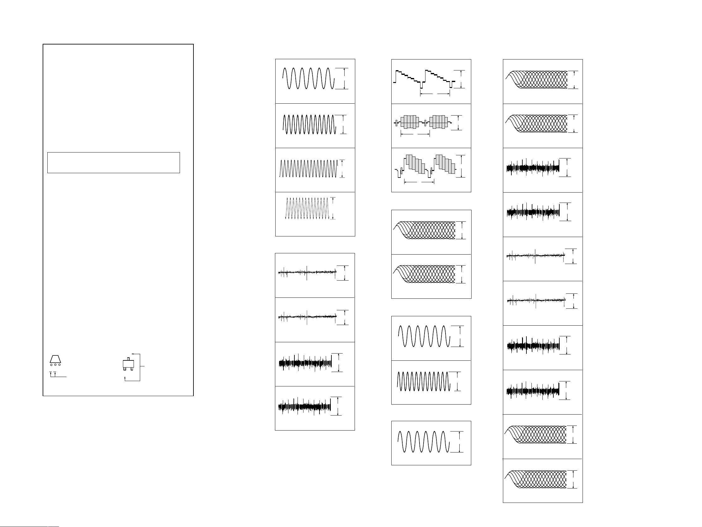
WAVEFORMS
– DVD (1/12) SECTION –
1
3.4Vp-p
27.0MHz
IC001 6
2
2.1Vp-p
33.8MHz
IC001 qs
3
2.8Vp-p
24.5MHz
IC001 qd
4
2Vp-p (DVD)
2.4Vp-p (CD)
DVD : 36.8MHz
CD : 33.8MHz
IC001 qj
– DVD (2/12) SECTION –
5
1.4Vp-p
500mV/DIV 50ms/DIV
IC701 yl DVD PLAY
6
1.7Vp-p
500mV/DIV 200ms/DIV
IC701 yl CD PLAY
7
220mVp-p
100mV/DIV 50ms/DIV
IC701 yk DVD PLAY
8
440mVp-p
500mV/DIV 50ms/DIV
IC701 yk CD PLAY
– DVD (4/12) SECTION –
9
1.0Vp-p
H
IC401 ya
q;
0.75Vp-p
H
IC401 ys
qa
1.2Vp-p
H
IC401 yg
– DVD (5/12) SECTION –
qs
1.5Vp-p
500mV/DIV 100ns/DIV
IC303 qj DVD PLAY
qd
1.5Vlp-p
500mV/DIV 500ns/DIV
IC303 ql CD PLAY
– DVD (8/12) SECTION –
qf
2.1Vp-p
12.4MHz
IC202 os
qg
2.5Vp-p
24.9MHz
IC202 5
– DVD (10/12) SECTION –
qh
1.8Vp-p
16MHz
IC903 qg
– TK SECTION –
1
200mV/DIV 100ns/DIV
IC001 1 DVD PLAY
2
500mV/DIV 500ns/DIV
IC001 1 CD PLAY
3
200mV/DIV 500ms/DIV
IC001 wl DVD PLAY
4
200mV/DIV 20ms/DIV
IC001 wl CD PLAY
5
500mV/DIV 50ms/DIV
IC001 el DVD PLAY
6
500mV/DIV 200ms/DIV
IC001 el CD PLAY
7
100mV/DIV 50ms/DIV
IC001 r; DVD PLAY
8
500mV/DIV 50ms/DIV
IC001 r; CD PLAY
9
500mV/DIV 100ns/DIV
IC001 tf DVD PLAY
q;
536
mVp-p
880
mVp-p
592mVp-p
448mVp-p
1.3Vp-p
1.7Vp-p
180mVp-p
860mVp-p
1.5Vp-p
1.5Vp-p
500mV/DIV 500ns/DIV
IC001 tf CD PLAY
2929
SAVA-D900/D900FR/D900R/SS-T900
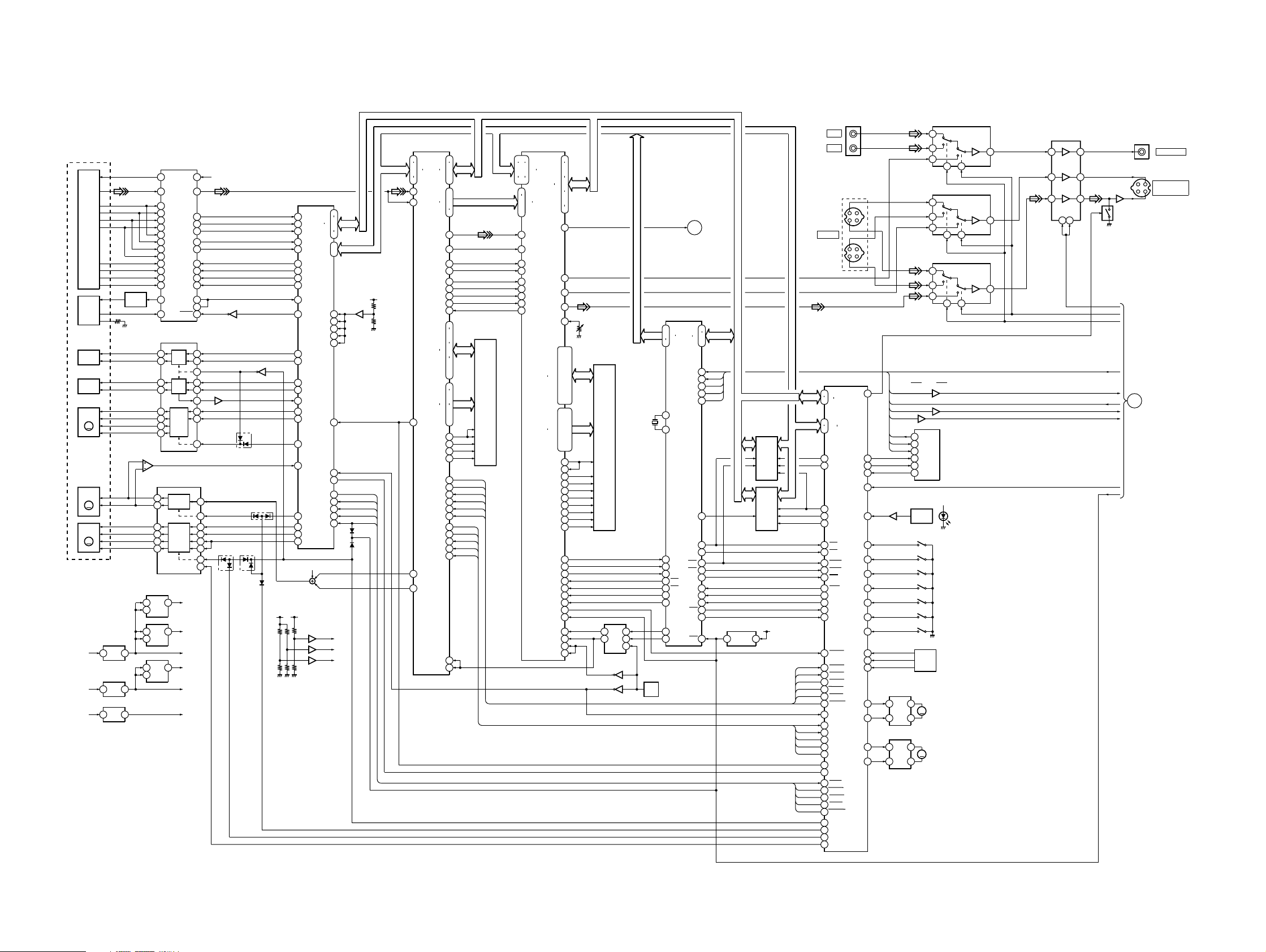
5-2. BLOCK DIAGRAMS
– DVD SECTION –
OPTICAL DEVICE
DVD/CD
PDIC
DVD/CD
LD MOD
FOCUS
COIL
TRACKING
COIL
TILT
MOTOR
SPINDLE
MOTOR
SLED
MOTOR
16
D+5V
F
F
F
IC203
12 11
13
46
6
IC201
IC201
5
EEPROM
4
3
8
1
D SENSOR
Q703
S707
ROTARY
ENCODER
M
M
LOADING
1
3
5
1
3
5
1
3
5
M701
CLAMP
MOTOR
M702
MOTOR
IC1101 VIDEO SWJ1102
2
2
2
+5V
S701
MID OUT
S703
MID IN
S708
OUT
S704
IN
S705
INIT
S706
COUNT
S702
LID
4
IC1102 Y SW
4
IC1103 C SW
4
D704
IC1104
MUTE
3 10
151
g
134
V MUTE
V SEL2
V SEL1
XIFOK
XVIFCS
IFSO0
IFSC0
XIFINT
XFRRST
IFSI0
Q1101
Q1805
Q1806
MAIN
SECTION
117
7
g
FF
7
7
J1103
MONITOR OUT
Y
J1105
MONITOR OUT
(S-VIDEO)
C
B
VIDEO
g
HD8-15
HA0-5,17-19
XARPIT
XARPWT
XARPWR
XARPRD
XARPCS
XARPRST
DFCT
NORF
FWON
MD2
MUTE
XSDPIT
XSDPRD
XSDPWR
XSDPCS
XSDPRST
INPUT
F
J1104
S-VIDEO
INPUT
133
126
154
146
124
125
112
113
4
141
142
144
143
145
157
156
155
3
135
72
107
108
109
110
111
106
59
103
102
104
99
98
105
54
115
117
116
118
114
93
57
91
92
AUX
IC601
HGA
HD0
HD7
HA0-5
HA17-19
XRAMUB
XRAMLB
XRAMOE
XRAMWE
XFBSY
CS1
CS4
HWRH
HWRL
HRD
WAIT
XINT1
XINT3
RST
CPUCK
AVDWT
ARPINT
ARPWT
ARPWR
ARPRD
ARPCS
ARPRST
MCK
DFCT
NORF
FWON
MD2
MUTE
LOCK
FCSON
SDPIT
SDPRD
SDPWR
SDPCS
SDPRST
XDRV MUTE
SPDL STOP
LDMN/DMM
LDMP/DMP
XECS
XEWC
XEBSY
DSW1
CKSW1
EXP2
CKSW2
DOOPN
SSW1
SSW2
SSW3
CKMP
CKMM
g
Y
C
Y
C
VS
EXPI
CS0L
53
SI0
SO0
SC0
SI0
SO0
SC0
23
24
25
22XIFINT
Q701
68
84
88
85
83
64
63DOCLS
73EXPI0
67
66
65
IC701
90
367
MOTOR
DRIVE
89
69TRMP
70TRMP
IC702
367
MOTOR
DRIVE
2
2
IC303
IC001
DVD/CD RF AMP
VC
RF
A
B
C
D
E
F
G
H
LD
DRIVER
PD
VR
F+
F-
T+
T-
TA+
TA-
TB+
M
TB-
SP+
SP-
M
SLA+
SLA-
SLB+
M
SLB-
IC501
+5V
1 3
REG
IC002
+5V
1 3
REG
IC905
+3.3V
1 3
REG
¥
Signal path.
J
: DVD/CD
c
: AUDIO (Digital)
g
: VIDEO
L
: C
F
: Y
DIGITAL SERVO
17
VC
1
RF IP
Jc
12
A
11
B
10
C
9
D
5
2A
6
2B
7
2C
8
2D
13
E
14
F
15
G
16
LD
IC803
12
13
514
514
514
IC302
+3.3V
IC302
+3.3V
IC005
+3.3V
14
16
15
14
13
12
11
REG
REG
REG
H
20
LD
19
PD
COIL/MOTOR
14
13
12
11
17
18
MOTOR
15
14
SPINDLE/SLED
MOTOR DRIVE
SPINDLE
MOTOR
MOTOR
IC801
DRIVE
F COIL
DRIVE
T COIL
DRIVE
TILT
DRIVE
IC802
DRIVE
SLED
DRIVE
Q001
SIGO
SCLK
SDEN
HOLD2
FDCHG
CLOCK
TZC
SWD
SRD
DFT
+3.3V
IC303
+3.3V
IC401
+5VA+10V
+3.3V
A+5V+12V
+3.3V
IC903
2VC
VCI
33
54
FE
40
TE
39
PI
29
26MIRR
32
43
44
45
46
42
31
Q002
27
2
3
9
5
6
IC702
7
23
26
20
26
20
3
6
5
2
D803 D804
9
23
Q801
13
D805
D801
D802
+3.3V
IC701
SERVO DSP
68
ADC1
HD0
69
ADC0
HD7
67
ADC2
21
TRIN
EA0
.
20
TRREF
EA1
41
GIO5
42
GIO6
43
GIO7
44
GIO8
28
DFCTI
38
VRBA
GIO11
DAB0
DAB1
DAB2
DAB3
85
DAB2
80
DAB3
97
DAB0
92
DAB1
66
ADC3
49
GIO1
48
GIO2
FG REF
46
GIO4
65
ADC4
X2/CLKIN
HWR
50
HCS
GIO0
RS
9
PWM0
8
PWM1
7
PWM2
1.6VC
+5V
IC803
75
810
13
125
122
120
117
74
81
84
93
96
22
108
39FCSON
128HINT
26
.
4
.
5
1HRD
2
3
2.5VC
2VC
1.6VC
HD8-15
HA0,1
D701
D807
IC702
75
XSDPRST
XSDPIT
XSDPRD
XSDPWR
XSDPCS
X3VRST
HA0-7
c
+3.3V
APR
73
76
.
79
82
17
19
58
49
52
A0
A7
RFIN1
RFIN2
LOCK
MDSO
MDPO
SD0
SD7
CD DATA
BCLK
LRVK
MD0
MD9
MA0
MA9
XCAS
XRAS
XMWR
XRST
DFCT
NORF
MCKI
SCKI
63
D0
68
.
HD8-15
D7
70
.
71
97
.
98
.
SD0-7
100
105
110DOUT
107
c
108
109
91SDCK
93XSHD
95XSAK
96SDEF
94XSRQ
154
157
.
159
162
.
164
167
.
169
.
IC304
172
136
139
141
144
146
147
150
151
XDE
152
148
83XINT
86XWAT
60XWR
61XRD
XCS
84
87
55
56
59FWON
113MD2
111MUTE
121
123
16M
DRAM
.
.
.
XARPIt
XARPWT
XARPWR
XARPRD
XARPCS
XARPRST
DFCT
NORF
FWON
MD2
MUTE
192
189
187
180
.
38
43
45
46
29
30
31
32
47
49
50
48
51
178
172
170
168
.
.
.
CDIN2I
CDIN1I
CDBCKI
CDLRCKI
ICLKI
ISTARI
IVALI
IERPI
IREGQN
IC401
AV DECODER
HAD0
HAD21
DT0
DT7
COMP OUT
SDDQ0
SDDQ15
SDAD0
SDAD11
SDDQM1O
SDDQM0O
SDWEON
SDCASON
SDCS0ON
SDCS1ON
DMRQ1ON
DMRQ0ON
DMACK1ON
DMACK0ON
15
12
.
10
HD0
7
.
HD8-15
HD15
5
2
.
208
205
27DO
cc
65
g
Y OUT
61
F
C OUT
62
VREF
70
RV401
VIDEO
SDCLKO
DCLKI
SDCKEO
SRASON
HIRQON
HAD23I
HAD22I
CLKIN
SCLKIN
LEVEL
134
156
.
.
137
153
.
.
140
150
.
.
143
147
.
.
146
144
.
.
149
140
.
.
152
138
.
.
135
113
.
111
.
108
.
106
.
105
.
107
IC402,403
155
110
112
115
117
116
118
127
125
122
131
132
123
130
129
121
120
196
200
202
166
167
199
201
198HWAITON
103RST IN
19ACLKIN
36CRPCLKIN
160
163
.
.
.
.
.
256FS30
33M30
27M30
N27M
16M
SDRAM
14
12
IC001
HA0-21
X201
12,5MHz
19
PLL
1
6
IC004
62
X001
27MHz
IC004
17
VCO
SPDIF
IC202
SYSTEM CONTROL
42
.
A0
44
A21
64
91
X1
92
X0
95
INT0
87
DREQ0
86
DREQ1
9
CS2
8
CS3
85
DACK0
84
DACK1
100
DVD/CD
66
CK SEL
A
MAIN
SECTION
D16
D31
SI0
SO0
SC0
SC0L
CS0
CS1
CS4
RD
RDY
INT1
INT3
25
39
HD0-15
.
41
XIFOK
96XIFOK
SI0
76
SO0
77
SC0
78
SC0L
97
IC204
1M
SRAM
IC205
16M
11
10
7
23WR0
24WR1
22
19
94
88
83ATG
5CLK
14RST
FLASH
+3.3V
IC207
4
5
RESET
3030
 Loading...