

Sony SATSLF-1 Service manual

SA-TSLF1
SERVICE MANUAL
Ver 1.0 2004.08
• SA-TSLF1 is surround speaker system (L)
in DAV-LF1.
SPECIFICATIONS
Surround (L)
Speaker system Two-way Closed box
Speaker unit 100 mm dia. cone type,
25 mm dia. balance-dome-
type tweeter
Rated impedance 4 ohms
Dimensions (approx.) 300 × 1205 × 300 mm
(w/h/d)
Mass (approx.) 6.5 kg
US Model
Canadian Model
AEP Model
UK Model
E Model
General
S
urround speaker (L)
Power requirements
North American and
Mexican models:
Taiwan model:
Other models:
Power consumption 45 W (220-240 V AC)
Design and specifications are subject to change
without notice.
120 V AC, 60 Hz
120 V AC, 50/60 Hz
220-240 V AC, 50/60 Hz
SURROUND SPEAKER SYSTEM
9-879-143-01
2004H1678-1
© 2004.08
Sony Corporation
Audio Group
Published by Sony Engineering Corporation
SA-TSLF1
r
TABLE OF CONTENTS
1. SERVICING NOTES ................................................ 3
2. GENERAL ................................................................... 4
3. DISASSMEBLY
3-1. Disassembly Flow ........................................................... 5
3-2. Speaker Body Section ..................................................... 6
3-3. Grille Assy ....................................................................... 7
3-4. AMP Assy........................................................................ 7
3-5. REAR PD JACK Board, REAR SP JACK Board ........... 8
3-6. DIAT POWER Board ...................................................... 9
3-7. Speaker Section ............................................................... 9
4. DIAGRAMS
4-1. Block Diagram ................................................................ 12
4-2. Printed Wiring Board – DIAT AMP Board (Side A) –... 13
4-3. Printed Wiring Board – DIAT AMP Board (Side B) –... 14
4-4. Schematic Diagram – DIAT AMP Board (1/3) – ........... 15
4-5. Schematic Diagram – DIAT AMP Board (2/3) – ........... 16
4-6. Schematic Diagram – DIAT AMP Board (3/3) – ........... 17
4-7. Printed Wiring Board – DIAT POWER Board – ............ 18
4-8. Schematic Diagram – DIAT POWER Board –............... 19
4-9. Printed Wiring Board – DIAT BUILT PD Section – ...... 20
4-10. Schematic Diagram – DIAT BUILT PD Section – ......... 21
5. EXPLODED VIEWS
5-1. Overall Section ................................................................ 26
5-2. Stand Section................................................................... 27
6. ELECTRICAL PARTS LIST .................................. 28
UNLEADED SOLDER
Boards requiring use of unleaded solder are printed with the leadfree mark (LF) indicating the solder contains no lead.
(Caution: Some printed circuit boards may not come printed with
the lead free mark due to their particular size)
Notes on chip component replacement
• Never reuse a disconnected chip component.
• Notice that the minus side of a tantalum capacitor may be
damaged by heat.
Flexible Circuit Board Repairing
• Keep the temperature of the soldering iron around 270 °C
during repairing.
• Do not touch the soldering iron on the same conductor of the
circuit board (within 3 times).
• Be careful not to apply force on the conductor when soldering
or unsoldering.
SAFETY CHECK-OUT
After correcting the original service problem, perform the following
safety check before releasing the set to the customer:
Check the antenna terminals, metal trim, “metallized” knobs, screws,
and all other exposed metal parts for AC leakage.
Check leakage as described below.
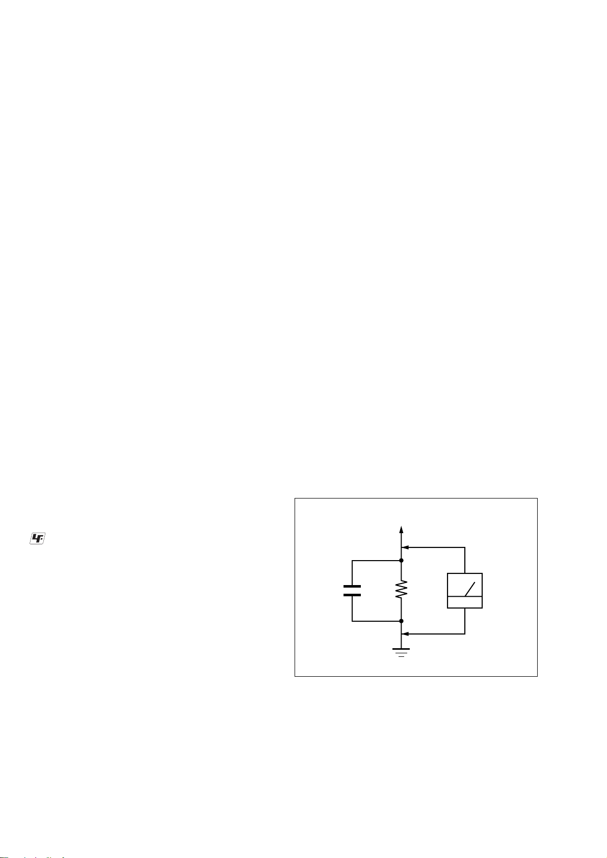
LEAKAGE TEST
The AC leakage from any exposed metal part to earth ground and
from all exposed metal parts to any exposed metal part having a
return to chassis, must not exceed 0.5 mA (500 microamperes.).
Leakage current can be measured by any one of three methods.
1. A commercial leakage tester, such as the Simpson 229 or RCA
WT -540A. Follow the manuf acturers’ instructions to use these
instruments.
2. A battery-operated A C milliammeter . The Data Precision 245
digital multimeter is suitable for this job.
3. Measuring the voltage drop across a resistor by means of a
VOM or battery-operated AC v oltmeter. The “limit” indication
is 0.75 V, so analog meters must have an accurate lo w-voltage
scale. The Simpson 250 and Sanwa SH-63Trd are examples
of a passive VOM that is suitable. Nearly all battery operated
digital multimeters that have a 2 V A C range are suitable. (See
Fig. A)
To Exposed Metal
Parts on Set
: LEAD FREE MARK
Unleaded solder has the following characteristics.
• Unleaded solder melts at a temperature about 40 °C higher
than ordinary solder.
Ordinary soldering irons can be used but the iron tip has to be
applied to the solder joint for a slightly longer time.
Soldering irons using a temperature regulator should be set to
about 350 °C.
Caution: The printed pattern (copper foil) may peel away if
the heated tip is applied for too long, so be careful!
• Strong viscosity
Unleaded solder is more viscou-s (sticky, less prone to flow)
than ordinary solder so use caution not to let solder bridges
occur such as on IC pins, etc.
• Usable with ordinary solder
It is best to use only unleaded solder but unleaded solder may
also be added to ordinary solder.
SAFETY-RELATED COMPONENT WARNING!!
COMPONENTS IDENTIFIED BY MARK 0 OR DOTTED LINE
WITH MARK 0 ON THE SCHEMATIC DIAGRAMS AND IN
THE PARTS LIST ARE CRITICAL TO SAFE OPERATION.
REPLACE THESE COMPONENTS WITH SONY PARTS WHOSE
PART NUMBERS APPEAR AS SHOWN IN THIS MANUAL OR
IN SUPPLEMENTS PUBLISHED BY SONY.
AC
0.15 µF
1.5 k
Ω
Earth Ground
voltmete
(0.75 V)
Fig. A. Using an AC voltmeter to check AC leakage.
ATTENTION AU COMPOSANT AYANT RAPPORT
LES COMPOSANTS IDENTIFIÉS PAR UNE MARQUE 0 SUR
LES DIAGRAMMES SCHÉMATIQUES ET LA LISTE DES
PIÈCES SONT CRITIQUES POUR LA SÉCURITÉ DE
FONCTIONNEMENT. NE REMPLACER CES COM- POSANTS
QUE PAR DES PIÈCES SONY DONT LES NUMÉROS SONT
DONNÉS DANS CE MANUEL OU D ANS LES SUPPLÉMENTS
PUBLIÉS PAR SONY.
À LA SÉCURITÉ!
2
SA-TSLF1
SECTION 1
SERVICING NOTES
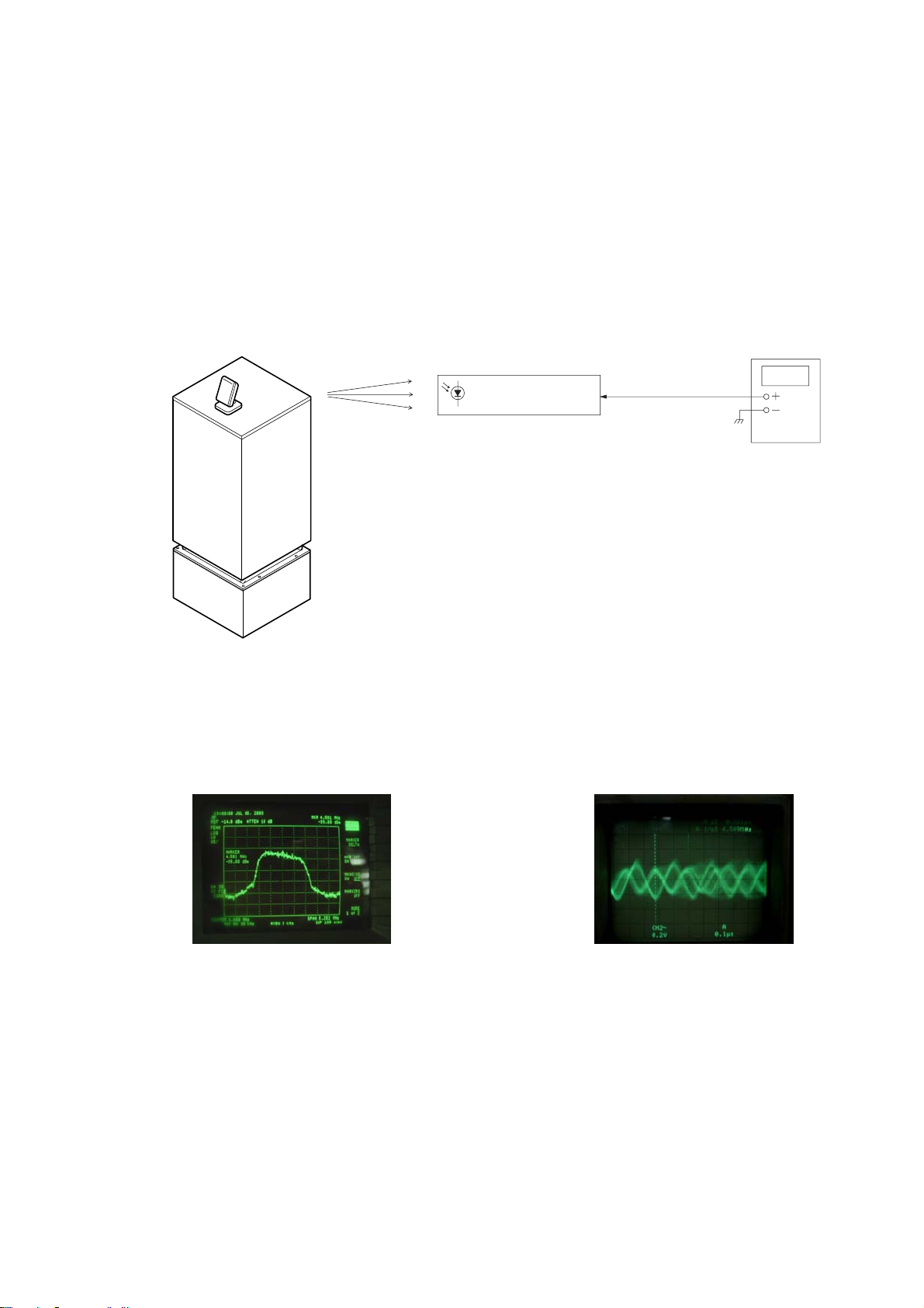
[AMP Board Input Signal Check Procedure]
Note 1:Connect the SA-WSLF1 to the HCD-LF1. Set up the system so that the infrared signal from IR transmitter (DIR-T1) can be received by the
rear speaker (SA-TSLF1).
Note 2: The POWER LED of this unit (SA-TSLF1) lights in red when the power of the SA-WSLF1 receiving waiting state (when data is not transmitted.)
When the power of the SA-WSLF1 is turned on and the infrared signal from IR transmitter (DIR-T1) is received by this unit (SA-TSLF1), the
POWER LED of this unit (SA-TSLF1) lights in green.
Check procedure:
1. Connect a spectrum analyzer and an oscilloscope to the connector CN7301 pin-2 of DIAT BUILT PD board.
IR transmitter
(DIR-T1)
2
RECEPTOR
DIAT BUILT PD board
Infrared
Transmission
* In the case of DIR-R3 is connected, the connector CN7301 pin-2 of
DIAT BUILT PD board is checked.
Subwoofer
(SA-WSLF1)
2. Confirm that the spectrum is displayed as shown in Fig. 1 on spectrum analyzer. Also confirm that the waveform as shown in Fig. 2
is displayed.
4.5MHz
↓
CN7301
pin
Spectrum analyzer
or Oscilloscope
Fig. 1 Fig. 2
3
SA-TSLF1
SECTION 2
GENERAL
This section is extracted
from instruction manual.
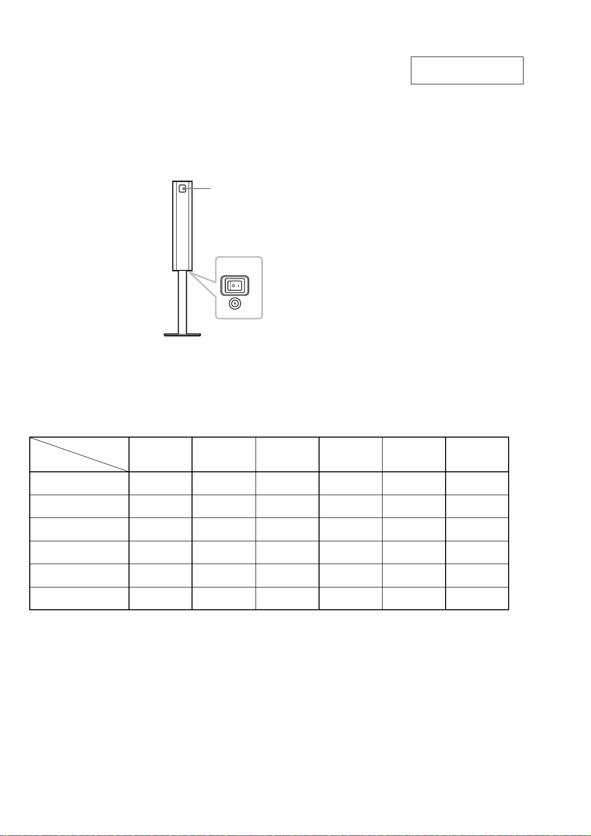
Surround speaker (L)
The surrou nd speaker (L) incorp or at es the IR rec ei ver, which receives the sound from t he IR
transmitter and sends it to the surr ound speaker (R).
Connect the s urround speaker (R) .
IR receiver
POWER
DIR-R3
• The units that are required for the system operation check during repair service
Units required for
Unit.
need to
checking
DVD player : HCD-LF1
Sub woofer : SA-WSLF1
Front speaker : SS-TSLF1(R)
Center speaker :
SS-CTLF1
Surround speaker : SS-TSLF1W(R)
Remote commander :
RM-SP320
*1 Only the defective unit. *2 Either one of them.
Units with a mark: The units that are required for the system operation check during repair service
However, there can be a case that some units of the system need to not be brought into repair shop depending on the unit. that became defective.
operation
check
SS-TSLF1L(L)
SA-TSLF1(L)
DVD player :
HCD-LF1
aa a
aa a
aaa
aaa a
Sub woofer :
SA-WSLF1
Front speaker :
SS-TSLF1(R)
SS-TSLF1L(L)
*1
*2
Center speaker :
SS-CTLF1
a
Surround speaker :
SS-TSLF1W(R)
SA-TSLF1(L)
*1
a
Remote
commander :
RM-SP320
a
a
4
SA-TSLF1
SECTION 3
DISASSEMBLY
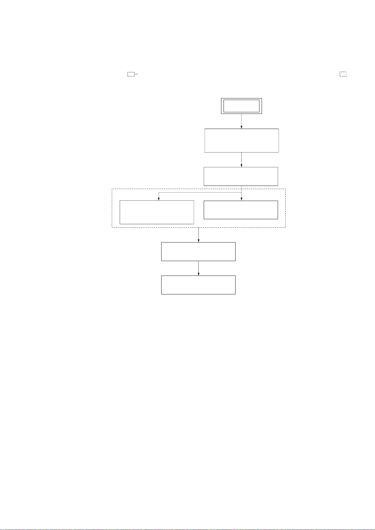
3-1. DISASSEMBLY FLOW
•This set can be disassembled in the order shown below.
•The dotted square with arrow ( ) prompts you to move to the next job when all of the works within the dotted square ( ) are
completed.
SET
3-2. SPEAKER BODY
SECTION
(Page 6)
3-3. GRILLE ASSY
(Page 7)
3-5. RER PD JACK BOARD,
REAR SP JACK BOARD
(Page 8)
3-6. DIAT POWER BOARD
3-7. SPEAKER SECTION
3-4. AMP ASSY
(Page 7)
(Page 9)
(Page 9)
5
SA-TSLF1
Note: Follow the disassembly procedure in the numerical order given.
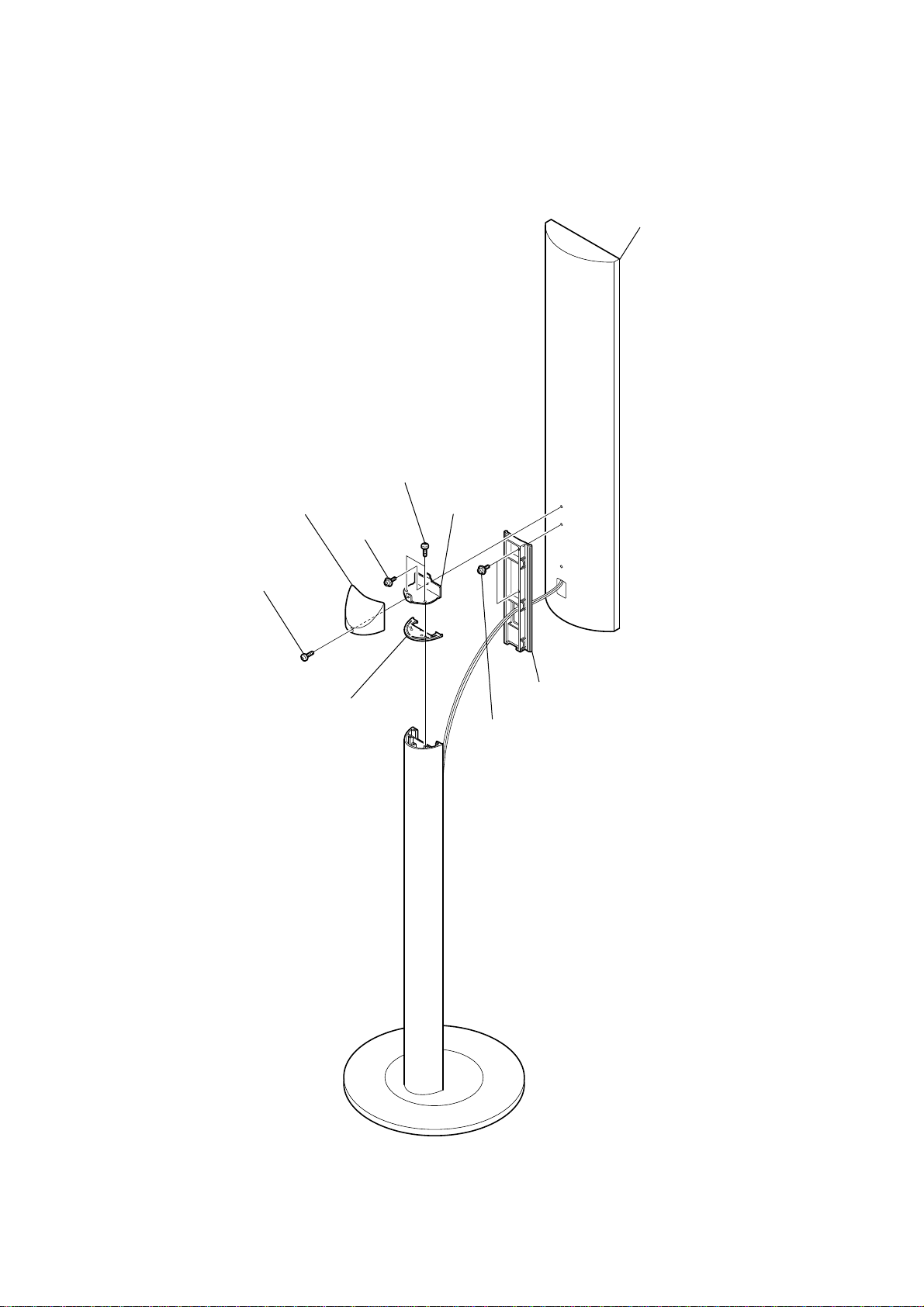
3-2. SPEAKER BODY SECTION
3
two screws
7
speaker body
1
screw(3.5)
2
top cover
4
screw
6
edge cover
5
L bracket
8
two screws
9
speaker bracket
6

3-3. GRILLE ASSY
3
two screws
1
grille frame
assy (rear)
4
cover (TOP)
2
twelve
catchers
SA-TSLF1
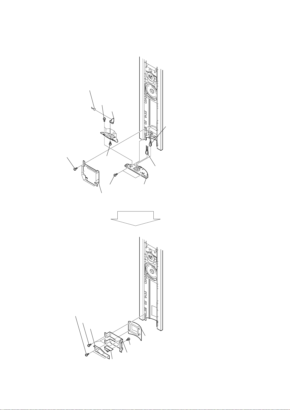
3-4. AMP ASSY
5
connector
3pin (CN104)
4
two screws
1
two screws
2
connector
2pin (CN7301)
6
REAR P LED board
3
qs
2pin (CN301)
8
wire earth
7
screw
qa
screws
q;
AMP cover
9
twelve screws
DIAT BUILT PD board
connector
four
ql
DIAT AMP
board
w;
AMP chassis
qj
connector
2pin(CN104)
qk
connector
2pin(CN302)
qd
connector
3pin(CN102)
qf
connector
6pin(CN103)
qg
connector
6pin(CN106)
qh
connector
2pin(CN105)
7
SA-TSLF1
3-5. REAR PD JACK BOARD, REAR SP JACK BOARD
8
connector
2pin(CN100)
7
six screws
q;
REAR PD
JACK board
4
power code
1
nine screws
9
screw
3
two screws
2
cover (SW)
5
cable (AMP)
6
bottom cover assy
qa
two screws
qd
three screws
qs
insulating sheet
qg
escution (CN)
qh
screw
qf
bracket (CN)
qj
REAR SP JACK board
8
3-6. DIAT POWER BOARD
4
four screws
3
sheet
8
DIAT POWER board
6
connector 7pin(CN103)
7
connector
7pin(CN106)
insulating
9
serial number
label
SA-TSLF1
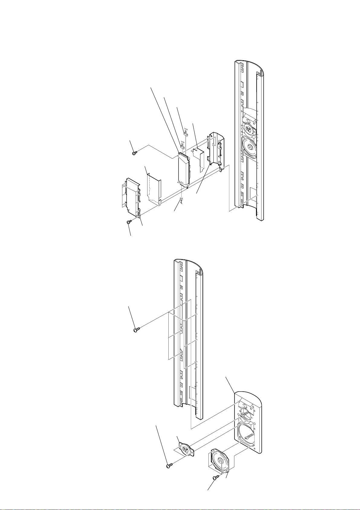
3-7. SPEAKER SECTION
2
cover (PW)
1
ten screws
3
six screws
(+BVTP 4
×
16)
q;
chassis (PW)
5
connector
2pin(CN903)
1
two screws
2
tweeter assy
5
four screws
4
speaker cabinet
6
speaker (10 cm)
9

SA-TSLF1
MEMO
10
SECTION 4
DIAGRAMS
SA-TSLF1
• Note for Printed Wiring Boards and Schematic Diagrams
Note on Printed Wiring Boards:
• X : parts extracted from the component side.
• Y : parts extracted from the conductor side.
• : Pattern from the side which enables seeing.
(The other layers' patterns are not indicated.)
Caution:
Pattern face side: Parts on the pattern f ace side seen from
(Side A) the pattern face are indicated.
Parts face side: Parts on the parts face side seen from
(Side B) the parts face are indicated.
• DIAT AMP board is multi-layer printed board.
However , the patterns of intermediate layers ha ve not been
included in diagrams.
• Indication of transistor.
C
Q
B
E
B
These are omitted.
Q
CE
These are omitted.
Note on Schematic Diagrams:
• All capacitors are in µF unless otherwise noted. (p: pF)
• All resistors are in Ω and 1/
• C : panel designation.
Note:
• A : B+ Line.
•Voltages and waveforms are dc with respect to ground
•Voltages are taken with a VOM (Input impedance 10 MΩ).
•Waveforms are taken with a oscilloscope.
• Circled numbers refer to waveforms.
• Signal path.
•Abbreviation
50 WV or less are not indicated except f or electrolytics and
tantalums.
specified.
The components identified by mark 0 or dotted line with mark 0 are
critical for safety.
Replace only with part
number specified.
under no-signal (detuned) conditions.
∗ : Impossible to measure
Voltage v ariations ma y be noted due to normal production
tolerances.
Voltage v ariations ma y be noted due to normal production
tolerances.
F : AUDIO
CND : Canadian model
E41 : Chilean and peruvian model
EA : Saudi Arabia model
HK : Hong Kong model
KR : Korea model
MX : Mexican model
RU : Russian model
4
W or less unless otherwise
Note:
Les composants identifiés
par une marque 0 sont critiques pour la sécurité.
Ne les remplacer que par une
piéce portant le numéro
spécifié.
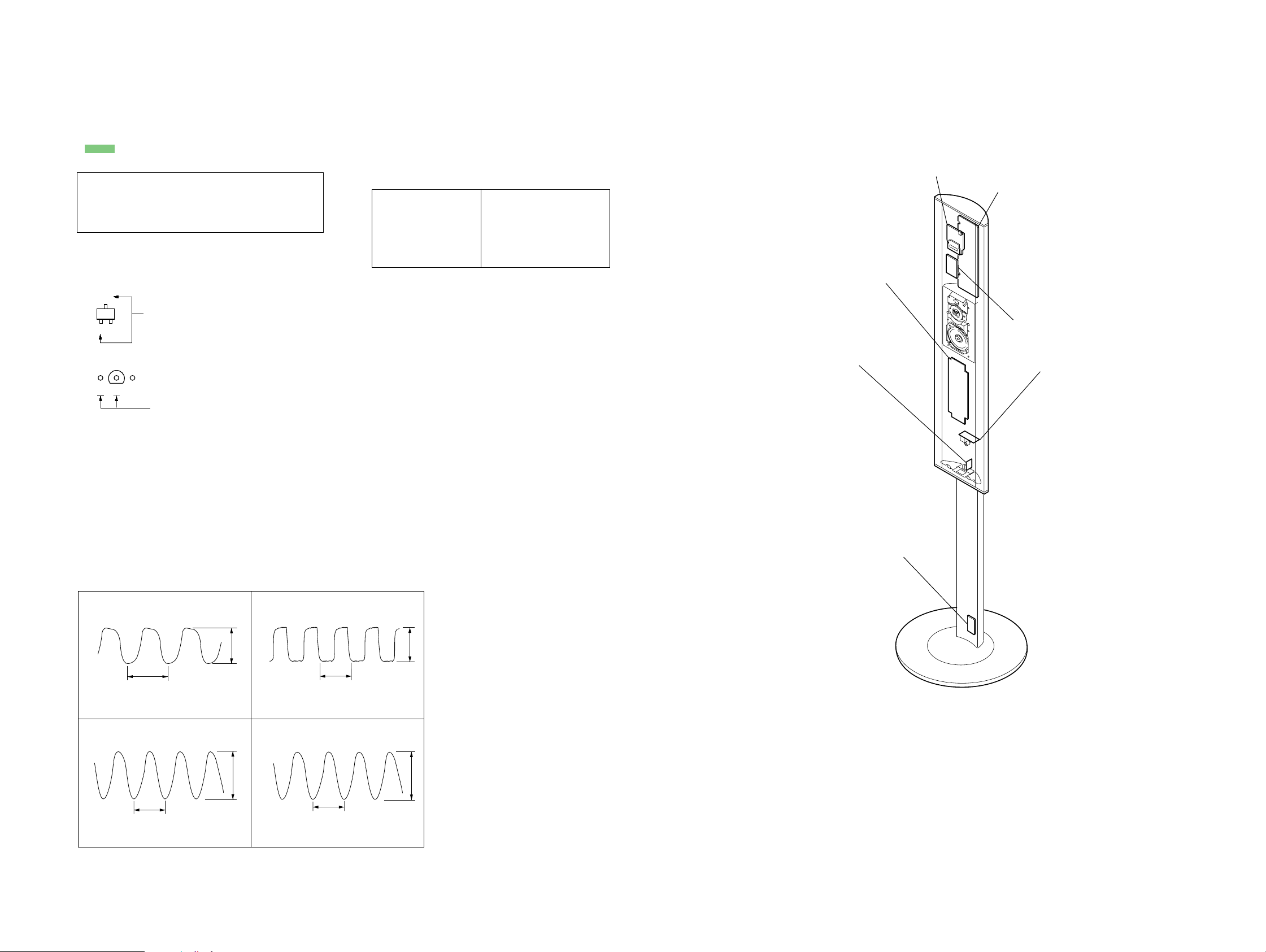
• Circuit Boards Location
DIAT BUILT PD board
DIAT POWER board
REAR SP JACK board
DIAT AMP board
REAR P LED board
REAR PD JACK board
•Waveforms
– DIAT AMP Board –
1
IC102 rd (OSCO)
81.3 ns
1 V/DIV, 50 ns/DIV
3
IC107 wd (X1)
125 ns
1 V/DIV, 50 ns/DIV
2.5 Vp-p
3.5 Vp-p
2
IC102 tf (BCK/RCLK)
325 ns
1 V/DIV, 100 ns/DIV
4
IC114 4
20.3 ns
2 V/DIV, 10 ns/DIV
REAR STAND board
2.5 Vp-p
4.5 Vp-p
SA-TSLF1
1111
 Loading...