

Page 1
R
®
DIRECTV
Digital Satellite Receiver
Operating Instructions
4-089-401-11
Before you begin using your Digital Satellite Receiver
for the first time, follow the instructions in “Getting Started”
on pages 1-6.
Also, make sure your Satellite Dish Antenna has been
properly installed and call your service provider to begin
service: DIRECTV: 1-800-DIRECTV (347-3288)
SAT-A65A
SAT-B65A
© 2002 Sony Electronics Inc. Reproduction in whole or in part without written
permission is prohibited. All rights reserved.
Page 2

Covered by one or more of the following U.S. Patents:
6,075,526;5,828,419; 5,751,372; 5,694,176; and 5,635,989. This
product is subject to one or more U.S. or foreign patents pending.
Sony Software License Agreement
ATTENTION: USE OF THE SOFTWARE IS SUBJECT TO THE
SONY SOFTWARE LICENSE TERMS SET FORTH ON PAGE 48.
USING THE SOFTWARE OR THE PRODUCT IN WHICH IT IS
INCORPORATED INDICATES USER’S ACCEPTANCE OF THESE
LICENSE TERMS. IF THE USER DOES NOT ACCEPT THESE
LICENSE TERMS, THE USER SHOULD IMMEDIATELY RETURN
THE ENTIRE PRODUCT IN ITS ORIGINAL PACKAGING IN ORDER
TO RECEIVE A FULL REFUND OF THE PURCHASE PRICE.
Disclaimer – Every effort has been made to ensure the correctness
and completeness of the material in this document. No company shall
be liable for errors contained herein. The information in this document
is subject to change without notice. No warranty of any kind is made
with regard to this material, including, but not limited to, the implied
warranties of merchantability and fitness for a particular pur pose.
Trademarks – Sony is trademark of Sony. DIRECTV and the Cyclone
Design logo, DIRECTV INTERACTIVE, DIRECTV MOVIES THIS
WEEK, DIRECTV SPORTS THIS WEEK, and DIRECTV SPORTS
are trademarks of DIRECTV, Inc., a unit of Hughes Electronics Corp.
FREEVIEW is a registered trademark of Hughes Electronics Corp.
All other trademarks and service marks are the property of their
respective owners.
Dolby Laboratories Information – Manufactured under license from
Dolby Laboratories. “Dolby,” “Pro Logic,” and the double-D symbol are
trademarks of Dolby Laboratories.
®
Macrovision
Information – Macrovision is a registered trademark
of Macrovision Corporation. This device incorporates an anticopy
process technology that is protected by U.S. patents 4,631,603;
4,577,216; 4,819,098; and other intellectual property rights. The
anticopy process is licensed for noncommercial, home use only.
Reverse engineering or disassembly is prohibited.
®
StarSight® Information – StarSight
features licensed under one or
more of the following patents: 4,706,121; 5,151,789; 5,353,121;
5,353,277; 5,479,266; 5,479,268; and 5,532,754. Use rights
reserved.
™
TruSurround™ Information – TruSurround
and the symbol
are trademarks of SRS Labs, Inc. TruSurround technology is
incorporated under license from SRS Labs, Inc.
Note on recording programming – Most television programs and
films are copyrighted. This means that someone has legal rights
governing the reproduction and distribution of this material. In certain
circumstances, copyright law may apply to private in-home taping of
copyrighted materials. In most cases, it is permissible to record for
your personal use, as long as you do not sell the material. You must
act responsibly in this area–check into the matter if you are unsure.
Some pay per view programs may be licensed from producers as
“view-only” programs. These are copyrighted programs, and may not
be copied or reproduced for any purpose without the express written
permission of the copyright owner.
DIRECTV
®
Programming – ACTIVATION OF PROGRAMMING
MAY BE SUBJECT TO CREDIT CARD APPROVAL AND
REQUIRES VALID SERVICE ADDRESS, SOCIAL SECURITY
NUMBER, AND/OR MAJOR CREDIT CARD. Programming subject
to change. You must be physically located in the United States (U.S.)
to receive DIRECTV service. DIRECTV services are not available
outside the United States. DIRECTV programming is sold separately
and independently of DIRECTV System hardware. A valid
programming subscription is required to operate DIRECTV System
hardware. © 2002 DIRECTV, Inc. DIRECTV and the Cyclone Design
logo are trademarks of DIRECTV, Inc., a unit of Hughes Electronics
Corp. Activate your DIRECTV programming today at
1-800-DIRECTV (1-800-347-3288).
DIRECTV System hardware and installation
To arrange for professional installation of your DIRECTV System,
ask questions, or resolve problems related to your DIRECTV System,
contact your dealer. If you need more information, please contact the
Sony Satellite System Information Center at 1-800-838-7669.
Please record the following information for warranty
System Model #: - _______________________
Receiver Model #: ___________________________
Receiver Serial #: ___________________________
Access Card #: _________ __________ _________
You are cautioned that any changes or modifications not expressly
approved in this manual could void your authority to operate this
equipment.
Page 3
For your safety and protection, read this entire Owner's Manual before you attempt to install or use your satellite
system. In particular, read this safety section carefully. Keep this safety information where you can refer to it if
necessary.
Important Safety Instructions
Heed Cautions–All cautions on the product and in the operating instructions should be adhered to.
Follow Instructions–All operating and use instructions should be followed.
THESE CAUTIONS AND SYMBOLS APPEAR ON THE BACK OF THE RECEIVER
WARNING or CAUTION
Double insulated systems are
protected by additional board
clearances and creepage, so
that the unit will not be a safety
hazard to the end-user.
IMPORTANT SAFETY INSTRUCTIONS
1. Read these instructions.
2. Keep these instructions.
3. Heed all warnings.
4. Follow all instructions.
5. Do not use this apparatus near water.
6. Clean only with dry cloth.
7. Do not block any ventilation openings. Install in
accordance with the manufacturer’s instructions.
8. Do not install near any heat sources such as
radiators, heat registers, stoves, or other apparatus
(including amplifiers) that produce heat.
9. Do not defeat the safety purpose of the polarized or
grounding-type plug. A polarized plug has two
blades with one wider than the other. A grounding
type plug has two blades and a third grounding
prong. The wide blade or the third prong is
provided for your safety. If the provided plug does
not fit into your outlet, consult an electrician for
replacement of the obsolete outlet.
CAUTION
RISK OF ELECTRICAL SHOCK
DO NOT OPEN
10. Protect the power cord from being walked on or
pinched particularly at plugs, convenience
receptacles, and the point where they exit from the
apparatus.
11. Only use attachments/accessories specified by the
manufacturer.
12. Use only with the cart, stand, tripod,
bracket, or table specified by the
manufacturer or sold with the
apparatus. When a cart is used, use
caution when moving the cart/apparatus
combination to avoid injury from tip-over.
13. Unplug this apparatus during lightning storms or
when unused for long periods of time.
14. Refer all servicing to qualified service personnel.
Servicing is required when the apparatus has been
damaged in any way, such as power-supply cord or
plug is damaged, liquid has been spilled or objects
have fallen into the apparatus, the apparatus has
been exposed to rain or moisture, does not operate
normally, or has been dropped.
iii
Page 4

INSTALLATION
Ground
clamp
Electric
service
equipment
Ground
clamps
Power service
grounding electrode
Grounding
conductor
Coaxial cable
Grounding block
Coaxial cable
Polarization – This DIRECTV® Receiver is equipped with a plug that will
fit into the power outlet only one way. Do not modify the plug defeating this
feature. If the plug does not fit, contact your electrician to replace your
outlet. To prevent electric shock, do not use this plug with an extension cord
or outlet unless you can fully insert the blades without blade exposure
Power Sources – Operate this DIRECTV Receiver only from the type of
power source indicated on the marking label. If you are not sure of the type
of power supply to your home, consult your dealer or local power company.
Power-Cord Protection – Protect the power cord from being walked on
or pinched particularly at plugs, convenience receptacles, and the point
where they exit from the apparatus.
Overloading – Do not overload wall outlets, extension cords, or integral
convenience receptacles as this can result in a risk of fire or electrical shock.
Ventilati on – Slots and openings in the cabinet are provided for ventilation
to ensure reliable operation of the product and to protect it from overheating.
Do not block any ventilation openings. Install in accordance with the
manufacturer’s instructions.
The openings should never be blocked by placing the product on a bed, sofa,
rug, or similar surface. This product should not be placed in a built-in
installation such as a bookcase or rack unless proper ventilation is provided
and the manufacturer’s instructions have been adhered to.
For electrical safety, power line operated equipment or accessories
connected to this unit should bear the UL listing mark and should not be
modified so as to defeat the safety features. This will help avoid any
potential hazard from electrical shock or fire. If in doubt, contact
qualified service personnel.
Heat–Do not install near any heat sources such as radiators, heat registers,
stoves, or other apparatus (including amplifiers) that produce heat.
Accessories – To avoid personal injury or damage to the DIRECTV
Receiver, do not place the DIRECTV Receiver on any unstable cart, stand,
table, or bracket. Any mounting of the product should follow the
manufacturer’s instructions.
Attachments – Do not use attachments unless recommended by
DIRECTV as they may cause hazards.
Satellite Dish Antenna Grounding – The outdoor satellite dish antenna
used to receive satellite signals and the cable used to connect the satellite
dish antenna to the indoor receiving unit are required to comply with local
installation codes and the appropriate sections of the National Electric Code
(NEC) and in particular Article 810-15, which covers proper installation and
grounding of television receiving equipment, as well as to Article 820-33,
which specifies that the satellite dish antenna cable ground shall be
connected to the grounding system of the building as close to the point of
cable entry as practical. These codes require proper grounding of the metal
structure of the outdoor satellite dish antenna and grounding of the
connecting cable at a point where it enters the house (or other building). If
you are having a professional installer perform the installation, the installer
must observe installation codes. This manual contains instructions on how to
make the installation in compliance with the NEC. If additional local
installation codes apply, contact local inspection authorities.
Example of Antenna Grounding according to the National
Electrical Code instructions contained in “Radio and Television
Equipment”.
Note: The DIRECTV Receiver shall be grounded through the satellite/
local antenna cable before plugging into the telephone jack, and it must
remain grounded thereafter.
Water and Moisture – WARNING! To reduce the risk of fire or electric
shock, do not expose this product to rain or moisture.
Lightning – For added protection for this product during a lightning storm,
or when it is left unattended and unused for long periods of time, unplug it
from the wall outlet, disconnect the antenna and cable system, and
disconnect it from the telephone line. This will prevent damage to the
product due to lightning and power-line surges.
Television Antenna Information – Installing an outdoor antenna can be
hazardous and should be left to a professional antenna installer. Do not
locate the outside antenna system in the vicinity of overhead power lines or
other electric light or power circuits, or where it can fall into such power
lines or circuits. When installing an outside antenna system, take extreme
care to keep from touching such power lines or circuits, as contact with them
might be fatal. If an outside antenna is connected to the DIRECTV Receiver,
be sure the antenna system is grounded so as to provide some protection
against voltage surges and built-up static charges. This DIRECTV Receiver
is equipped with a plug that will fit into the power outlet only one way. Do
not modify the plug defeating this feature. If the plug does not fit, contact
your electrician to replace your outlet. To prevent electric shock, do not use
this plug with an extension cord or outlet unless you can fully insert the
blades without blade exposure. Section 810 of the NEC, NFPA No. 70 1987,
provides information with respect to proper grounding of the mast and
supporting structure, grounding of the lead-in wire to an antenna discharge
unit, size of the grounding conductors, location of antenna discharge unit,
connection to grounding electrodes, and requirements for the grounding
electrode.
Power Lines – Extreme care must be taken when installing and adjusting
or maintaining the outdoor antenna and connecting cable, especially in the
vicinity of overhead power lines, electric lights, or power circuits. When
installing the outdoor antenna or cable, extreme care should be taken to keep
from touching or approaching such power lines or circuits, as contact with
them might be fatal.
Cleaning – Unplug this receiver from the wall outlet before cleaning. Do
not use liquid or aerosol cleaners. Use only a damp cloth for cleaning.
Object and Liquid Entry – Never push objects of any kind into this
DIRECTV Receiver through openings as they may touch dangerous voltages
or “short out” parts that could result in a fire or electric shock. Never spill
liquid of any kind on the receiver. No objects filled with liquids, such as
vases, shall be placed on the apparatus.
iv
Page 5

SERVICE
Servicing–Do not attempt to service this DIRECTV® Receiver yourself as
opening or removing covers may expose you to dangerous voltage or other
hazards. There are no user serviceable parts inside. Refer all servicing to
qualified service personnel.
Conditions Requiring Service–Unplug the DIRECTV Receiver from
the wall outlet and refer servicing to qualified personnel under the following
conditions:
•When the power supply cord or plug has been damaged.
•If liquid has been spilled on, or objects have fallen into, the DIRECTV
Receiver or it has been exposed to water.
•If the DIRECTV Receiver does not operate normally by following the
operating instructions. Adjust only those controls that are covered by the
operating instructions. Other adjustments may result in damage and will
often require extensive work by a qualified technician to restore the
DIRECTV Receiver to its normal operation.
•If the DIRECTV Receiver has been dropped or the cabinet has been
damaged.
•When the DIRECTV Receiver exhibits a distinct change in performance.
Replacement Parts–When replacement parts are required, have the
technician verify that the replacements being used have the same safety
characteristics as the original parts.
Use of replacement parts specified by the manufacturer can prevent fire,
electric shock, or other hazards.
Safety Check–Upon completion of any service or repairs to this
DIRECTV Receiver, ask the service technician to perform safety checks
recommended by the manufacturer to determine that the DIRECTV Receiver
is in safe operating condition.
Your DIRECTV Receiver is able to receive upgrades or modifications to
some of its features and functions. These modifications will occur
automatically, usually at times when the receiver would likely be turned off.
If your receiver is on when an upgrade or modification is sent, you may
experience a disruption in reception for a minute or two. Your reception
should return to normal after the modification is complete. Your receiver
must be plugged in to receive any upgrades. Do not unplug your receiver
while an upgrade is in progress. Please consult the Upgrade menu to find a
schedule of upgrades or modifications planned by DIRECTV.
With this receiver (SAT-A65A, SAT-B65A) and the proper satellite dish
antenna, you may be able to subscribe to local channels from DIRECTV in
certain areas. Additional equipment may be required in some markets.
Check with your retailer or visit DIRECTV.com for information on
availability of local channels from DIRECTV in your area.
v
Page 6

Federal Communications Commission (FCC) Regulatory Information
Declaration of Conformity– Standards to which Conformity is declared: FCC Part15
This Device complies with Part 15 of the FCC Rules. Operation is subject to the following two conditions: (1) this device may not cause harmful
interference, and (2) this device must accept any interference received, including interference that may cause undesired operation.
• Responsible Party’s Name: Sony Electronics Inc.
Address: 680 Kinderkamack Road, Oradell, NJ 07649 U.S.A
Telephone: 1-800-858-7669
• Trade Name: Sony
• Type of Equipment: Satellite Receiver
• Model Numbers: SAT-A65A, SAT-B65A, RM-Y812, RM-Y807
Federal Communications Commission (FCC)–This equipment complies with both Part 15 and Part 68 of the FCC rules.
Part 15 Compliance–This equipment has been tested and found to comply with the limits for a Class B digital device, pursuant to Part 15 of the FCC rules.
These limits are designed to provide reasonable protection against harmful interference in a residential installation. This equipment generates, uses, and can
radiate radio frequency energy and, if not installed and used in accordance with the instructions, may cause harmful interference to radio communications.
However there is no guarantee that interference will not occur in a particular installation. If this equipment does cause harmful interference to radio or
television reception, which can be determined by removing and applying power to the equipment, you are encouraged to try to correct the interference by one
or more of the following measures:
• Reorient or relocate the receiving satellite dish antenna.
• Increase the separation between the equipment and the DIRECTV
• Connect the equipment into an outlet on a circuit different from that to which the DIRECTV Receiver is connected.
• Consult the dealer or an experienced radio/TV technician for help.
The user may find the following booklet, prepared by the Federal Communications Commission, helpful: “How to Identify and Resolve Radio and TV
Interference Problems.” This booklet is available from the U.S. Government Printing Office, Washington, DC.
To meet FCC requirement, only peripherals (computer input/output devices, terminals, printers, etc.) certified to comply with Class B limits may be attached
to this device. Operation with noncertified peripherals is likely to result in interference to radio and TV reception.
To meet FCC requirements, shielded cables are required to connect the device to a personal computer, peripheral, or other Class B certified device.
Part 68 Compliance –This equipment complies with Part 68 of the FCC rules. On the modem card is a label that contains, among other information, the
FCC registration number and Ringer Equivalence Number (REN) for this equipment. If requested, this information must be provided to the Telephone
Company.
The REN is used to determine the quantity of devices which may be connected to the telephone line. Excessive RENs on the telephone line may result in
devices not ringing in response to an incoming call. In most, but not all areas, the sum of the RENs should not exceed five (5). To be certain of the number of
devices that may be connected to the line, contact the Telephone Company to determine the maximum number of RENs for the calling area.
If the DIRECTV Receiver (Model Numbers: (SAT-A65A, SAT-B65A) terminal equipment causes harm to the telephone network, the Telephone Company
will notify you in advance that temporary discontinuance of service may be required. But, if advance notice is not practical, the Telephone Company will
notify you as soon as possible. Also, you will be advised of your right to file a complaint with the FCC, if you believe it is necessary. The Telephone Company
may request that you remove the equipment from the network until the problem is resolved.
The Telephone Company may make changes in its facilities, equipment, operations, or procedures that could affect the operation of the equipment. If this
happens, the Telephone Company will provide advance notice in order for you to make the necessary modifications in order to maintain uninterrupted service.
If you have trouble with the DIRECTV Receiver (Model Numbers: SAT-A65A, SAT-B65A) equipment, please contact
Sony Satellite System Information Center at 1-800-858-SONY (7669)
for repair and/or warranty information.
Sony must make any necessary repairs to the modem portion of this equipment in order to maintain valid FCC registration. Do not attempt to repair or service
your modem. Return it to Sony.
No repairs can be made by customers. All repairs must be done by an authorized Sony Service Center. This equipment cannot be used on public coin service
provided by the Telephone Company. Connection to Party Line Service is subject to state tariffs.
®
Receiver.
vi
Page 7

Contents
Getting started. . . . . . . . . . . . . . . . . . . . . . . . 1
Setup overview . . . . . . . . . . . . . . . . . . . . . . . . . . . . 1
Attach the antenna cable . . . . . . . . . . . . . . . . . . . 2
Connect your TV. . . . . . . . . . . . . . . . . . . . . . . . .3
Determine antenna angles . . . . . . . . . . . . . . . . . .4
Testing your system . . . . . . . . . . . . . . . . . . . . . . 5
Adding system components . . . . . . . . . . . . . 7
Connecting components . . . . . . . . . . . . . . . . . . . . .7
Connect a terrestrial antenna. . . . . . . . . . . . . . . . 7
Connect the RF remote control antenna
(SAT-A65A only) . . . . . . . . . . . . . . . . . . . . . . . . .7
Connecting a VCR . . . . . . . . . . . . . . . . . . . . . . .8
Connect the VCR Control Cable
(SAT-A65A only) . . . . . . . . . . . . . . . . . . . . . . . . .8
Test the VCR (Record/Stop)
(SAT-A65A only) . . . . . . . . . . . . . . . . . . . . . . . . .9
Connecting a home entertainment system. . . . . . .10
Using the remote control . . . . . . . . . . . . . . 11
Remote control functions . . . . . . . . . . . . . . . . . . . 15
Installing remote control batteries. . . . . . . . . . . 15
Programming the remote control. . . . . . . . . . . . 16
Changing the remote default . . . . . . . . . . . . . . .16
Using DIRECTV INTERACTIVE™
powered by Wink Communications® . . . . . . . . . . 16
Using the menus . . . . . . . . . . . . . . . . . . . . . 17
Purchasing pay per view (PPV) . . . . . . . . . . . . . . 18
Cancelling purchases. . . . . . . . . . . . . . . . . . . . .18
Setting guide preferences . . . . . . . . . . . . . . . . . . . 19
Using the Timer. . . . . . . . . . . . . . . . . . . . . . . . . . . 19
To schedule or edit an event . . . . . . . . . . . . . . . 20
Adjusting audio . . . . . . . . . . . . . . . . . . . . . . . . . . . 20
Using Dolby Digital audio (SAT-A65A only) . . 21
Setting default and alternate audio . . . . . . . . . .21
Adjusting audio balance . . . . . . . . . . . . . . . . . .22
Adjusting video . . . . . . . . . . . . . . . . . . . . . . . . . . . 22
Using Caller ID . . . . . . . . . . . . . . . . . . . . . . . . . 23
Using Search . . . . . . . . . . . . . . . . . . . . . . . . . . . . .23
Adjusting system settings . . . . . . . . . . . . . . . . . . .24
New Access Card . . . . . . . . . . . . . . . . . . . . . . . 24
Change Receiver ID . . . . . . . . . . . . . . . . . . . . . 25
Set output channel. . . . . . . . . . . . . . . . . . . . . . . 25
Input key enable/disable . . . . . . . . . . . . . . . . . . 25
Lock a channel . . . . . . . . . . . . . . . . . . . . . . . . . 25
Select menu language . . . . . . . . . . . . . . . . . . . . 26
Change color schemes. . . . . . . . . . . . . . . . . . . . 26
Set translucency level . . . . . . . . . . . . . . . . . . . . 26
Caller ID enable/disable . . . . . . . . . . . . . . . . . . 26
Restore factory default settings. . . . . . . . . . . . . 26
Viewing Messages . . . . . . . . . . . . . . . . . . . . . . . . 26
Using program guides . . . . . . . . . . . . . . . . .27
Selecting a program guide style . . . . . . . . . . . . . . 27
Grid guide . . . . . . . . . . . . . . . . . . . . . . . . . . . . . 27
Logo guide . . . . . . . . . . . . . . . . . . . . . . . . . . . . 28
Program guide and menu features . . . . . . . . . . . . 29
The OneLine™ Guide. . . . . . . . . . . . . . . . . . . . . . 30
Using Channel Mark. . . . . . . . . . . . . . . . . . . . . . . 31
Setting favorites and filters . . . . . . . . . . . . .33
Using favorite channel lists. . . . . . . . . . . . . . . . . . 33
Creating a channel list. . . . . . . . . . . . . . . . . . . . 33
Renaming a channel list:. . . . . . . . . . . . . . . . . . 34
Creating an Auto Set list. . . . . . . . . . . . . . . . . . 34
Adding and removing all channels . . . . . . . . . . 34
Filtering the program guide . . . . . . . . . . . . . . . . . 35
Using Theme Filters . . . . . . . . . . . . . . . . . . . . . 35
Selecting guide times . . . . . . . . . . . . . . . . . . . . 36
Using access controls . . . . . . . . . . . . . . . . . .37
Locking & unlocking the system . . . . . . . . . . . . . 37
How to lock the system. . . . . . . . . . . . . . . . . . . 37
Unlocking the system . . . . . . . . . . . . . . . . . . . . 38
Setting ratings limits . . . . . . . . . . . . . . . . . . . . . 38
Setting spending and time limits. . . . . . . . . . . . 39
Questions & Answers . . . . . . . . . . . . . . . . . .41
Manufacturers device control codes . . . . . .45
Index . . . . . . . . . . . . . . . . . . . . . . . . . . . . . . .51
Contents vii
Page 8

viii Contents
Page 9

You may connect a second
DIRECTV Receiver to the unused
LNB output. These instructions
also apply to an additional
receiver.
Getting started 1
This chapter explains how to:
• Connect the DIRECTV
(this page).
• Connect your DIRECTV Receiver to your TV (see page 3).
• Find antenna azimuth and elevation settings for your location (see page 4).
• Test the DIRECTV System operation (see page 5).
How to use this manual
This manual uses these typographical conventions to help clarify instructions:
Text Example Description
Click Cancel.
Highlight the Messages
button.
Press the INFO button.
Connect a pair of A/V
cables to the
AUDIO IN jack.
Highlight the Options tab.
Display the MAIN MENU.
®
satellite dish antenna to your DIRECTV Receiver
On-screen command buttons that execute an action.
Pull-down and pop-up box selections, or other option
buttons within a menu pane.
Remote control buttons, or receiver front panel.
Names of equipment cable connections on
equipment.
Menu tab names
Menu and pane names, names of pop-up and
sub-menu panes.
Setup overview At this point, you should have:
• Mounted the DIRECTV satellite antenna and pointed it in the general
direction of the satellite.
• Grounded the antenna as described in your antenna installation instructions.
• Attached RG-6 coaxial cable(s) to the antenna LNB connector(s).
• Routed the other end of the antenna cable to the back of your DIRECTV
Receiver.
• Placed the DIRECTV Receiver accessible to a telephone modular jack.
Ensure that you have completed these procedures, then continue to the next
page to begin installing the DIRECTV Receiver.
Getting started 1
Page 10
Attach the antenna cable
You can configure your system several ways, depending on what additional
components (such as a VCR, DVD player, or A/V receiver) you select. For now,
however, use the simplest configuration to check your antenna and cabling.
• Ensure that the DIRECTV
®
Receiver is not plugged into an electrical outlet.
• Attach the RG-6 coaxial antenna cable to the SATELLITE IN connector on
the back of the DIRECTV Receiver. Refer to the appropriate figure below.
VHF/UHF IN
R
VHF (SAT)
/UHF OUT
TEL LINE
Model: SAT-B65
Digital Satellite Receiver
Sony Electronics, Inc.
Made in Mexico
1
2345678
9
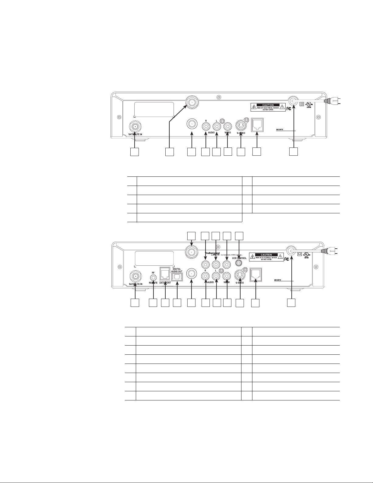
Table 1: Rear panel connections - SAT-B65A DIRECTV Receiver
1 SATELLITE IN connector 6 VIDEO OUTPUT jack
2 VHF/UHF IN connector 7 S-VIDEO jack
3 VHF (SAT)/UHF OUT connector 8 TELEPHONE JACK
4 AUDIO OUTPUT (R) jack 9 AC POWER CORD
5 AUDIO OUTPUT (L) jack
8 10
6
VHF/UHF IN
VHF (SAT)
/UHF OUT
21 4 5 7 9
3
12
11
14
13
TEL LINE
15
R
Model: SAT-A65
Digital Satellite Receiver
Sony Electronics, Inc.
Made in Mexico
16
Table 2: Rear panel connections - SAT-A65A DIRECTV Receiver
1 SATELLITE IN connector 9 AUDIO OUTPUT (L) jack
2 RF REMOTE antenna jack 10 AUDIO OUTPUT (L) jack
3 DATA PORT 11 VIDEO OUTPUT jack
4 DIGITAL AUDIO OUTPUT optical jack 12 VIDEO OUTPUT jack
5 VHF (SAT)/UHF OUT connector 13 S-VIDEO jack
6 VHF/UHF IN connector 14 VCR CONTROL cable jack
7 AUDIO OUTPUT (R) jack 15 TELEPHONE JACK
8 AUDIO OUTPUT (R) jack 16 AC POWER CORD
2 Getting started
Page 11

Connect your TV
Depending on your TV, you can connect it to the receiver in one of three ways:
• S-Video cable (best picture quality) or
• Video cable (very good picture quality) or
• Coaxial cable (good picture quality)
In addition to your video connection, use a set of audio cables (L/R) to provide
stereo sound. If your TV does not have audio jacks, you will hear monophonic
audio. This is acceptable for the procedures described in the next section.
To connect your TV to the DIRECTV
®
Receiver:
1. Select the appropriate connection:
If your TV has an S-Video jack –
• Use an S-Video cable (supplied with SAT-A65A only) to connect the
DIRECTV Receiver’s
• Use audio cables to connect the DIRECTV Receiver’s
the TV’s
AUDIO IN jacks.
S-VIDEO jack to the TV’s S-VIDEO jack.
AUDIO jacks to
If your TV has RCA-type A/V connectors –
• Connect the DIRECTV Receiver’s
A/V IN jacks.
TV’s
• If your TV has only one
jack to the TV AUDIO IN jack.
L
AUDIO IN jack, connect the receiver’s AUDIO
AUDIO and VIDEO jacks to the
If your TV only has an RF (coaxial) connector –
• Connect the DIRECTV Receiver’s
the TV’s
VHF/UHF IN or RF IN jack.
VHF (SAT)/UHF OUT connector to
2. Connect one end of the telephone line cord provided into the DIRECTV
Receiver’s PHONE JACK.
3. Connect the other end into a modular telephone outlet.
4. Plug the TV into an electrical outlet.
5. Plug the DIRECTV Receiver power cord into an electrical outlet. If the
front panel Power indicator does not illuminate, press the
POWER button.
Onscreen Menu Icons
These icons appear in onscreen menus and are used throughout this manual:
Toggle or Step Press SELECT to toggle (switch) a setting from ON to OFF or
step through the available choices each time you press SELECT.
List of Options Menu button will display a list of choices in a pop-up menu when
you press SELECT.
Series of Boxes Multiple screens will appear in a series requesting you to enter
numbers and/or letters for the particular feature when you
press SELECT.
Getting started 3
Page 12
Determine antenna
angles
This section explains how to determine the proper antenna position. This is
expressed in degrees of azimuth (horizontal) and elevation (vertical). Use the
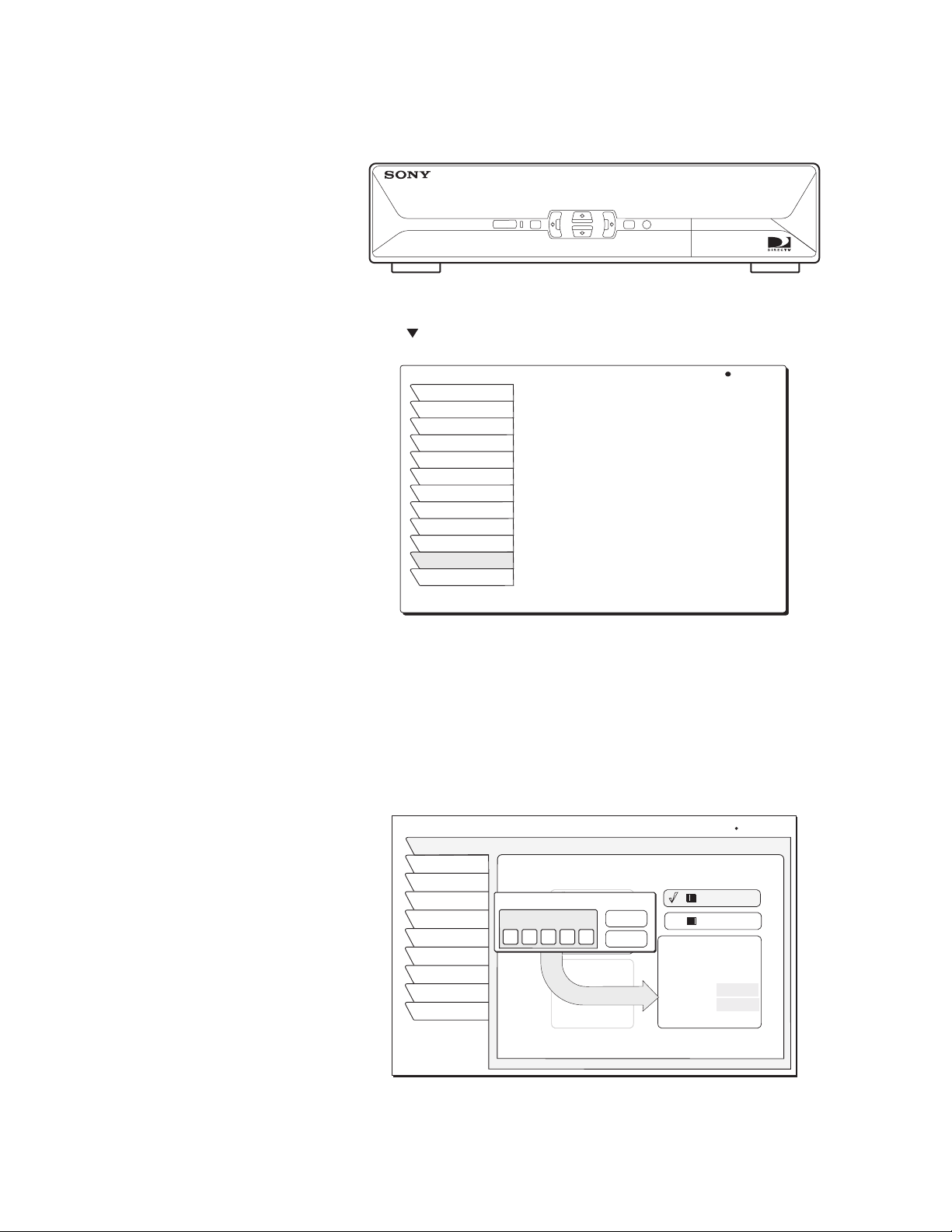
receiver front panel controls shown below to complete this procedure.
MENU
POWER
1. Press the front panel
MENU button to display the MAIN MENU below.
2. Use the button to highlight the
MAIN MENU Wed, Feb 20 8:45PM
Program Guide
Guide Options
Audio & Video
Caller ID
Program Director
Watchword
Interactive
Purchases
Lock & Limits
View Mail
System Setup
Watch TV
SELECT
System tab.
DIGITAL SATELLITE RECEIVER SAT-A
60
Tilt angle also appears if you
select an Oval Antenna from the
Dish Type menu.
Main Menu tabs
3. Press the front panel
SELECT button.
4. The ANTENNA INSTALL menu allows you to determine the correct antenna
position using your 5-digit ZIP code. Enter your ZIP code and press
SELECT.
The correct azimuth and elevation angles appear as shown below.
5. Use these values to properly align your dish antenna.
ANTENNA INSTALL
Antenna
Signal
VCR
Prefs
Test
New Card
Upgrades
Features
Watch TV
Main Menu
Dish Type Alignment
Round Dish
ZIP Code Entry
ZIP Code
Oval Dish 2
2 0 9 0 2
Oval dish 3
Round dish
for 1
satellite
location
Cancel
Wed, Sep 5, 3:31 PM
OK
ZIP Code: 20902
Latitude:
Longitude:
Elevation: 38
Azimuth: 224 SW
Tilt:
ZIP Code
Lat/Long
4 Getting started
Finding antenna settings based on ZIP code
Page 13

Testing your system
When you have aligned your dish antenna to the azimuth and elevation angles
shown on the
Antenna pane:
1. Highlight the
Signal tab.
2. Use the button to highlight the Source pull-down menu
3. Signal quality is indicated by a scale at the bottom of the pane and with an
audible indication. The frequency and tempo of the tone increase with
signal strength.
SIGNAL STRENGTH
Antenna
Signal
VCR
Prefs
Test
New Card
Upgrade
Features
Exit
Return
Signal Strength
Source
o
Satellite 101
Current: 95 Highest: 95
(A)
Status: Unlocked
Wed, Aug 1 5:14 PM
Transponder
04
4. Highlight the Transponder pull-down menu.
5. You may need to select another transponder to achieve the highest signal
indication.
6. Select the transponder providing the best signal.
7. Use the button to highlight the
8. Highlight Begin Test and press the
Test tab.
SELECT button.
Results appear within a few seconds and should resemble those in the figure.
If your test results are much different from those shown in the figures, or you
receive no signal indication, refer to page 6.
SYSTEM TEST
Antenna
Signal
VCR
Prefs
Test
New Card
Upgrade
Features
Exit
Return
System Test
Begin Test
Version
Wink Version
Signal
Tuning
Phone
Access Card
Front Panel
Wed, Aug 1 5:12PM
Xponder Test
: 5317.6
: 0.0.0.75
:OK
:OK
:OK
:OK
(ID 0000-0000-0000)
:OK
To perform the Transponder test:
1. Move the highlight to the Xponder Test pull-down menu.
2. Press the
SELECT button.
Getting started 5
Page 14

3. Press SELECT again to test the first selection on the pop-up menu.
SYSTEM TEST
Antenna
Signal
VCR
Prefs
Test
New Card
Upgrade
SYSTEM TEST
Features
Antenna
Exit
Signal
Return
VCR
Prefs
Test
Test
New Card
Upgrade
Features
Exit
Return
Begin Test
Begin Test
18
916
1724
2532
System Tests
Xponder Test
Satellite 101 (A) Signal Strength
95
94
93
94
Wed, Jun 13 10:15 PM
Xponder Test
Satellite 101 (A)
: 5317.6
Satellite 119 (B)
:0.0.0.75
Satellite 110 (C)
:OK
Cancel
:OK
System Tests
94
95
95
94
93
94
93
93
95
95
95
94
Wed, Jun 13 10:16 PM
Xponder Test
93
94
95
95
94
94
92
94
93
93
92
93
92
94
94
93
Your results will differ slightly from those shown, depending on your
geographic location and specific installation. However, if your results are very
different from these examples (i.e, rows of zeros or single-digit numbers):
• Highlight the Antenna tab on the ANTENNA SETUP menu, then carefully
verify your settings for accuracy.
INSTALLATION
Install
Signal
VCR
Prefs
Test
New Card
Upgrade
Features
Exit
Return
Dish Pointing
Dish Type
Autoconfig
Dish Type:
Oval Dish 2
Networks:
0, 3
Switch Type:
Simple
LNB: Unstacked
Antenna Setup pane
Wed, Feb 13 12:16PM
Alignment Mode
ZIP Code
Lat/Longitude
ZIP Code :
Latitude :
Longitude :
Elevation :
Azimuth :
Tilt :
• Re-enter your ZIP code if necessary to verify you have used the correct
antenna pointing parameters for your location.
• Check your cable connections.
• Ensure the DIRECTV
®
Receiver is connected to a modular telephone jack.
6 Getting started
Once you have successfully obtained a signal and your test results resemble
those shown in the figures, call DIRECTV (or your subscription service
provider) to activate service if you have not done so already.
Page 15
Adding system components 2
You can configure your DIRECTV® Receiver several ways depending on the
additional audio/video components you want to use.
This chapter explains how to:
• Connect a terrestrial (broadcast) TV antenna (this page).
• Connect the optional RF remote control antenna (this page).
• Connect and set-up a VCR (see page 8).
• Integrate the DIRECTV Receiver into your existing audio or A/V system
(see page 10).
Connecting
components
Connect a terrestrial
antenna
Connect the RF remote
control antenna
(SAT-A65A only)
At this point, you should have:
Verified that your system is operating properly.
Connected your DIRECTV Receiver to your TV.
Unplugged all components from electrical outlets.
You can connect a terrestrial (broadcast) TV antenna to your DIRECTV
Receiver by connecting it to the DIRECTV Receiver’s
(refer to figures on page 2). The remote control
switch between DIRECTV
antenna.
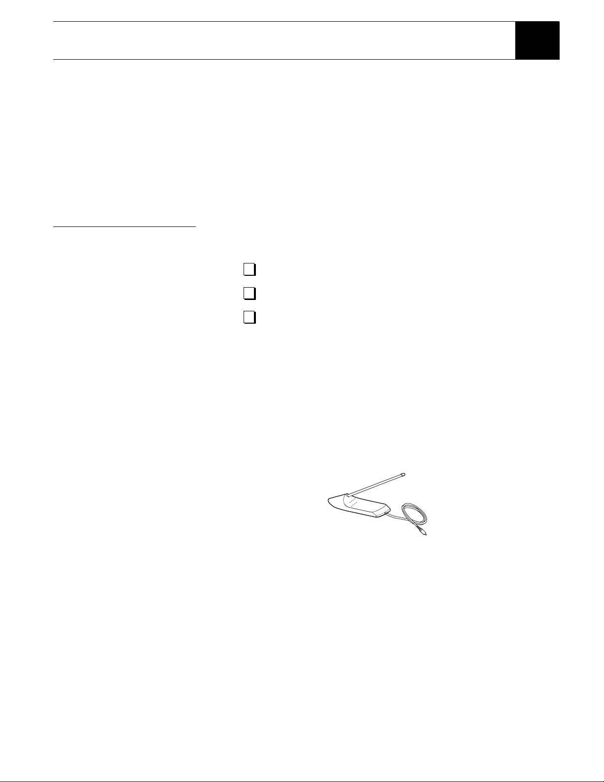
The SAT-A65A DIRECTV Receiver uses an optional RF (radio frequency)
remote control antenna that allows you to control your receiver from other
rooms in your house.
®
programming and input from the terrestrial
INPUT button allows you to
TV ANT/CABLE IN jack
RF Antenna
1. Plug the RF remote control cable into the
DIRECTV Receiver rear panel (refer to figures on page 2.)
2. Extend the cable and place the antenna in the desired location
To achieve the best operating range from the remote control, position the
antenna as high and as far away from metal objects as possible.
RF REMOTE connector on the
Adding system components 7
Page 16
Connecting a VCR
Follow these instructions to connect your TV and VCR to the DIRECTV®
Receiver. Connect the satellite antenna RG-6 coaxial cable to the DIRECTV
Receiver’s
SATELLITE IN jack (refer to figures on page 2).
1. Depending on your VCR, select the appropriate connection to the
DIRECTV receiver:
If your VCR has A/V connectors –
• Connect the DIRECTV Receiver’s
VCR’s
A/V IN jacks.
AUDIO and VIDEO jacks to the
If your VCR only has an RF (coaxial) connector–
• Connect the DIRECTV Receiver’s
VHF/UHF IN or RF IN jack.
• If your VCR has only one
(mono)
AUDIO L jack to the VCR’s AUDIO IN jack.
AUDIO IN jack, connect the receiver’s lower
OUT TO TV connector to the VCR’s
2. Depending on your TV and VCR, select the appropriate method to the
connect the VCR to the TV:
If your TV and VCR have A/V connector –
• Connect the DIRECTV Receiver’s
A/V IN jacks.
TV’s
AUDIO and VIDEO jacks to the
If your TV or VCR only has an RF (coaxial) jack –
• Connect the VCR’s
VHF/UHF OUT jack to the TV’s VHF/UHF IN jack.
3. Plug the TV, VCR, and DIRECTV Receiver power cords into an electrical
outlet.
Connect the VCR Control
Cable (SAT-A65A only)
Using the VCR Control Cable provided, the SAT-A65A DIRECTV Receiver
can control your VCR for unattended recording.
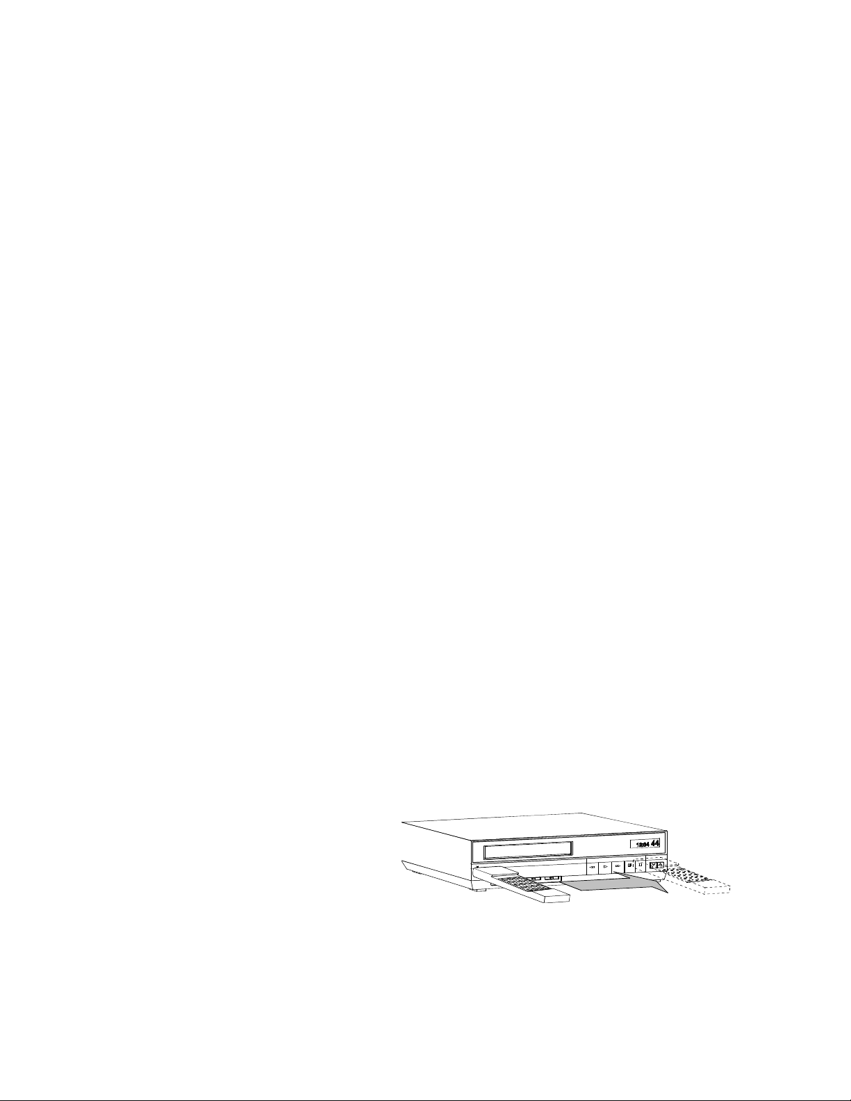
1. Plug the VCR control cable into the rear panel VCR CONTROL jack.
2. Temporarily position the other end over the VCR’s remote control sensor
(normally a small dark plastic window on the VCR front panel).
The remote control sensor may be labeled or identified in your VCR manual.
If it is not identified, scan the front of the VCR with your VCR remote control:
3. Hold the VCR remote control about ½-inch (1.3 cm) from the front left side.
4. Slowly move the remote control to the right as shown in the figure.
5. Repeatedly press the remote control’s power key on and off.
Scanning for the VCR remote control sensor
6. When your VCR responds to your pressing the remote control power, note
the position. Temporarily tape the emitter to the position you marked until
you verify that it works properly.
8 Adding system components
Page 17

7. Test the VCR control feature as described below.
8. Remove the temporary mounting tape. Attach the emitter permanently with
peel-and-stick backing. This will not interfere with normal VCR operation.
®
The VCR SETUP menu provides the settings to allow the DIRECTV
Receiver to communicate with your VCR.
Test the VCR
(Record/Stop)
(SAT-A65A only)
VCR SETUP
Install
Signal
VCR
Prefs
Test
New Card
Upgrade
Features
Exit
Return
Brand
Admiral
Aiwal
Akai
Audio Dynamics
Bell & Howell
Brooksonic
Canon
Select a code
1
2
3
4
5
Thu, Aug 2 2:22 PM
TestCode
Record
Stop
Clear
9. Scroll through the VCR brands using the navgation buttons. If you cannot
find the correct code listed for your brand of VCR, try related brands that
use the same code. Your VCR may also respond to multiple codes.
10. Use the remote control
SELECT button to try each code.
11. Alternate between this procedure and testing the code.
This Record/Stop test verifies the specified brand and code controls your VCR.
Before starting the test:
• Turn the VCR power on.
• Verify the VCR Control Cable is properly connected.
• Insert a recordable videotape into the VCR.
Signals coming from the remote
control at the same time as
signals coming from the VCR
Control cable may provide
unreliable test results.
Use the DIRECTV Receiver front panel controls, rather than the remote control,
to test the codes.
Test the VCR record and stop commands. If either command does not function,
try other codes shown for your VCR brand. If you are unsuccessful after trying
all available codes, recheck your VCR Control Cable connections and IR
emitter placement.
Adding system components 9
Page 18

Connecting a home
entertainment
system
The A/V receiver must be turned
on in order to send the video
signal to your TV.
You can integrate the DIRECTV® Receiver into your entertainment system to
take advantage of enhanced audio and video capability. Follow these
instructions to connect your DIRECTV Receiver.
• To connect the DIRECTV Receiver to your audio system, use A/V cables to
connect the satellite receiver to the audio receiver’s
AUDIO IN jacks. Refer
to the figures on page 2 for rear panel connector locations.
• Dolby Digital - With the SAT-A65A model, you can enjoy programs that
contain a Dolby Digital sound track. We recommend that you listen in
surround sound for maximum enjoyment of these programs. You can
connect the stereo outputs of the SAT-A65A to a receiver that contains a
Dolby Surround Pro Logic decoder. This will provide you with three audio
channels in the front and a mono surround channel.
• To take full advantage of Dolby Digital programming, connect the
SAT-A65A digital audio output to an external 5.1-channel Dolby Digital
decoder or receiver. This provides you with three front channels, two
independent surround channels, and a sub-woofer channel.
1. Connect the satellite antenna RG-6 coaxial cable to the DIRECTV
Receiver’s
SATELLITE IN jack.
2. Connect the DIRECTV Receiver’s
A/V jacks.
A/V jacks to the VCR and A/V receiver’s
3. AUX, optical connection, and digital output connections – If your audio
receiver has coaxial or optical digital connectors, connect the appropriate
type of cable to the DIRECTV Receiver’s
DIGITAL AUDIO OUT (SAT-A65A
only) for two-channel digital stereo. If your A/V receiver is also capable of
decoding Dolby Digital, use this connection in order to listen in full
5.1-channel surround sound. Additional audio information begins on
page 20.
4. Connect the VCR’s
A/V OUT jacks to a pair of the A/V receiver’s A/V IN
jacks.
5. Connect the A/V receiver’s
MONITOR OUT jack to the TV’s VIDEO IN
jack.
6. Plug the components into an electrical outlet.
Note: If you have connected a VCR to your entertainment system in a way
that routes the satellite receiver’s signal to your VCR before it reaches the
TV, you may see a distorted picture if you try to record a copy-protected
program. A
programs. If this occurs, simply stop recording and the picture will
automatically correct itself.
Can’t Tape symbol in the screen banner identifies these
10 Adding system components
Page 19

Using the remote control 3
This chapter explains how to:
• Use the RM-Y812 and RM-Y807 remote control functions. (see page 15)
• Install and replace the remote control batteries. (see page 15)
• Program the remote to work with your system components. (see page 16)
• Access interactive programming features. (see page 16)
MUTING button - Mutes the volume. Press
1
again to restore the volume. To operate your
TV, you must first set up the remote control
(see pages 15
TV/VIDEO button - Switches between the
2
inputs of your TV. To operate your TV, you
must first set up the remote control
(see pages 15
TV/VCR button - Switches between the
3
inputs of your VCR. To operate your VCR,
you must first set up the remote control
(see pages 15
TV/SAT button - Switches your satellite
4
receiver output between regular TV and
satellite broadcasts. To receive regular TV
broadcasts, you must have a local TV
antenna or cable connection.
Subchannel button - Use with the 0-9
5
buttons to select digital video subchannels
(if available).
DISPLAY button - Displays information for
6
the current program.
EXIT button - Closes all on-screen displays.
7
MENU button - Opens the Main Menu.
8
VOL button - Adjust the volume. To operate
9
your TV, you must first set up the remote
control (see pages 15
CODE SET button - Lets you program the
10
remote control to operate your TV and other
audio/video equipment (see pages 15–16).
POWER buttons - Turn on and off the
11
Satellite Receiver, TV, and VCR. To operate
your TV or VCR, you must first set up the
remote control (see pages 15
FUNCTION buttons - Select the equipment
12
(SAT,TV,VCR) that you want to operate. The
indicators light up to show which device the
remote control is operating.To operate your
TV or VCR, you must first set up the remote
control (see pages 15
VCR Control buttons - Operate VCR features
13
such as play, record, pause, stop, and fast wind.
To operate your VCR, you must first set up the
remote control (see pages 15
–16).
–16).
–16).
–16).
–16).
–16).
–16).
10
MUTING
VCR
VCR
TV
FUNCTION
TVTV/VIDEO
1
2
3
TV/VCR
TV/SAT
4
1283
456
79
5
6
7
VOL
8
9
CODE SET
RM-Y812
Continued on next page
0
FAVORITEDISPLAY
SELECT
SEARCHMENUEXIT
SATELLITE
RECEIVER
JUMP
GUIDE
CH
POWER
SAT
SAT
PAG E
RM-Y812
11
12
13
14
15
16
17
18
19
20
21
22
Using the remote control 11
Page 20

0-9 buttons - Change channels directly
14
MUTING
1
2
3
VCR
VCR
TV/VCR
TV/SAT
4
TV
FUNCTION
TVTV/VIDEO
POWER
SAT
SAT
11
12
13
1283
456
14
and enter numerical values in onscreen
displays.
JUMP button - Changes channels to
15
the previously tuned channel.
GUIDE button - Opens the Program
16
Guide.
FAVORIT E butt o n - Changes the guide
17
to the next Favorite Stations.
5
6
10
79
JUMP
0
FAVORITEDISPLAY
GUIDE
15
16
17
SELECT
18
19
20
21
VOL
SEARCHMENUEXIT
CH
7
8
9
CODE SET
PAG E
RM-Y812
22
Navigation buttons - The navigation
18
buttons move the highlight in on-screen
displays. If there is no on-screen
display, the up/down buttons activate
the one-line guide.
SELECT button - The SELECT button
19
selects the highlighted item.
20
21
22
button- Access interactive
features.
SEARCH button - Access the Search
feature to find favorite programs.
CH +/–/PAGE buttons - Change
channels. When a program guide is
open, these buttons page through the
guide.
SATELLITE
RECEIVER
RM-Y812
12 Using the remote control
Page 21

The MUTING, SLEEP and VOL +/buttons are set to control an audio
receiver unless the Device Switch is
set to “TV”. To change this setting,
see Changing the remote default on
page16
.
MUTING button - Mutes the volume of the
1
audio receiver. Press again to restore the
volume. To operate your TV, move the device
switch to TV or see Changing the remote
default on page 16. To operate your audio
receiver or TV, you must first set up the
remote control (see pages 15
SLEEP button - Sets the audio receiver to
2
turn off automatically after a certain amount of
time (if your audio receiver has a compatible
Sleep feature). To operate your TV, move the
device switch to TV or see Changing the
remote default on page 16. To operate your
audio receiver or TV, you must first set up the
remote control (see pages 15
SOUND FIELD +/– buttons - Switches
3
between the various Sound Field settings of
compatible audio receivers. To operate your
audio receiver, you must first set up the
remote control (see pages 15–16).
0-9 buttons - Change channels directly, and
4
enter numerical values in on-screen displays.
Subchannel button - Use with the 0-9
5
buttons to select digital video subchannels
if available (for example, 2.1).
DISPLAY button - Opens the program
6
information display for the current program.
MENU button - Opens the Main Menu.
7
–16).
–16).
1
2
3
4
5
6
7
10
11
12
13
14
15
16
17
18
19
20
21
8
9
22
23
24
25
26
VOL (Volume) +/– button - Adjusts the audio
8
receiver volume. To operate your audio
receiver or TV, you must first set up the
remote control (see pages 15
Navigation button - The navigation buttons
9
move the highlight in the on-screen displays.
When no menus are displayed, pressing the
up or down navigation buttons activate the
one-line guide.
SEARCH button - Access the SEARCH
10
feature to find favorite programs.
AUDIO buttons - Changes the audio track of
11
the current DVD in the DVD Player (if
available). To operate your DVD Player, you
must first set up the remote control
(see pages 15–16).
CODE SET button - Lets you program the
12
remote control to operate your TV and other
audio/video equipment (see pages 15–16).
AMP POWER button - Turn on and off the
13
audio receiver.To operate your audio receiver,
you must first set up the remote control
(see pages 15
–16).
–16).
RM-Y807
Continued on next page
Using the remote control 13
Page 22

1
2
3
4
5
6
7
8
9
10
11
12
RM-Y807
13
14
15
16
17
18
19
20
21
22
23
24
25
26
TV/AV POWER button - Turn on and off
14
the TV. To turn on and off the DVD or
VCR, move the device switch to DVD or
VCR. To operate your TV, DVD, or VCR,
you must first set up the remote control
(see pages 15
POWER button - Turn on and off the
15
satellite receiver.
TV/VIDEO button - Switches between
16
the inputs of your TV. To operate your
TV you must first set up the remote
control (see pages 15
TV/SAT button- Switches the signal
17
being output by the VHF(SAT)/UHF
OUT jack from the SATELLITE IN to
VHF/UHF IN.
PIC MODE button - Switches between
18
the Picture Mode setting of compatible
TVs. To operate your TV you must first
set up the remote control (see pages
15–16).
JUMP button- Changes channels to the
19
previously tuned channel.
FAVORITE button - Toggles the
20
Favorite Stations guides.
GUIDE button - Opens the Program
21
Guide.
CH (Channel) +/– button - Changes
22
channels. When a program guide is
open, pressing the CH button pages
through the guide.
SELECT button - Access the Search
23
feature to find favorite programs.
24
25
button - Access interactive
features.
VCR/DVD Control buttons - Operate
VCR/DVD features such as play, record,
pause, stop, and fast wind. To operate
your VCR/DVD you must first set up the
remote control (see pages 15–16).
–16).
–16).
14 Using the remote control
Device switch (TV/VCR/DVD/SAT
26
switch) - Set the remote to operate
other devices in your home theater.
To operate these other devices, you
must first set up the remote control
(see pages 15
–16).
The DIRECTV® Receiver front panel buttons can provide the basic controls
needed to access major DIRECTV System features. However, using the remote
control simplifies accessing the basic system functions, enhances your system’s
capabilities, and provides convenient shortcuts to extended features.
Additionally, some remote control buttons can also control other home
entertainment system components.
Page 23

Remote control
functions
The navigation buttons are the most versatile (and most used) remote control
feature. Using only the navigation buttons, you can perform virtually all
on-screen functions including:
• Selecting a highlighted screen menu item.
• Moving the screen highlight (or cursor) up, down, left and right.
• Jumping directly to the OneLine™ Guide.
• Changing channels using the OneLine Guide.
Use the navigation buttons to move up, down, left, or right through the
on-screen displays.
Press the navigation buttons up or down to display the OneLine guide while you
are watching a program. When the OneLine guide appears, press the navigation
buttons up or down to step to the next higher- or lower-numbered channel.
Installing remote control
batteries
Press the
time (while a program title is highlighted) to display the
Press the
GUIDE button to display the current program guide. Press it a second
Guide Options menu.
DISPLAY button to display a brief description about the program you
are viewing. For more details, press it again to display the Information Banner.
DISPLAY button provides scheduling information (and pay per view
The
purchase information) about the program highlighted in the program guide. See
Chapter 5 – Using program guides, on page 27 for more information.
Use the
CHANNEL (CH +/–) button to move up or down to the next available
channel in the OneLine Guide or scroll through a page of program guide
selection.
Press the
EXIT button to exit from any on-screen guide, remove banners, or
terminate an action.
RM-Y807 Remote Control:
Move the device switch to
SAT to control the DIRECTV
®
Receiver. The other
positions on the device switch indicate the devices they control.
RM-Y812 Remote Control:
Press the
SAT function button to control the DIRECTV Receiver. The other
function buttons indicate the devices they control.
To install or replace the remote control batteries:
1. Locate the battery compartment on the back of the remote control.
2. Remove the battery compartment cover.
3. Insert two “AA” size batteries as shown, observing the correct polarity.
4. Replace the battery compartment cover.
Using the remote control 15
Page 24

Programming the remote
control
The RM-Y807 and RM-Y812 remote controls can be programmed to operate
your other audio/video equipment.
1. Find the code(s) for the manufacturer of the device you want to operate with
this remote control. You can find these codes on pages 45 and 46.
2. Press the
CODE SET button.
3. Press the 0-9 buttons to input the manufacturer code. Then Press the
SELECT button. The remote is set up to operate that device.
4. Test the remote control. Press the
press other operation controls such as the
POWER button for that equipment, then
(CH +/–) buttons. If the device
does not respond to the remote control, repeat the procedure from step 2 and
enter a different manufacturer code in step 3.
Changing the remote
default
Using DIRECTV
™
INTERACTIVE
powered by Wink Communications
The RM-Y807 remote is set to control an audio receiver using the MUTING,
SLEEP, and VOL +/– buttons unless the device switch is set to TV. This setting
can be changed so that these buttons always control the TV.
1. Press the
2. Use the
SELECT button. Press the SELECT button a second time.
3. The
CODE SET button.
0-9 buttons to enter the numbers “1,” “0,” “0,” then press the
MUTING, SLEEP, and VOL +/– buttons are now always set to control
the TV.
4. To return to the default setting, follow the above step, but enter the numbers
9,” “9,” “9” in step 2
“
DIRECTV INTERACTIVE powered by Wink Communications® is a free,
easy-to-use service that allows you to interact with the television shows and
advertisements. When the blinking symbol appears in the upper left part of
®
your screen, you know that the program you're watching has been enhanced
with DIRECTV INTERACTIVE.
Simply press the button on your remote control.You can use your remote
control to access up-to-the-minute sports scores, news and weather, get program
trivia, respond to offers during commercials, and purchase products, all while
watching TV.
16 Using the remote control
DIRECTV INTERACTIVE
Interact
Exit
Return
Select the DIRECTV INTERACTIVE
DIRECTV INTERACTIVE
Check your local weather, see the latest
sports scores, interact with popular
shows and shop from your couch. It is
FREE, easy to use and lots of fun!
Go to the DIRECTV INTERACTIVE Center
to get started
DIRECTV INTERACTIVE Center
Center menu bar, then follow the simple
directions provided on the subsequent screens.
Thu, Aug 2 11:32 AM
TM
TM
TM
Page 25

Using the menus 4
This chapter describes:
• How to find the menus you need to perform common tasks (this page).
• How to purchase pay per view events (see 18).
• Using the Timer (see 19).
• How to set and modify preferences (see 19).
The table below lists the
MAIN MENU tabs, their submenus, and what they do.
Menu function overview
Main Menu tab Screens (see page) If you want to:
Program Guide Program Guide • View and modify the program guide.
Guide Options Theme (19)
Times (36)
Favorites List (33)
Favorites Setup (33)
Set Options (33)
Set Channel Mark (31)
Audio & Video Audio Adjustment (20)
Video Adjustment
Caller ID Caller ID (23, 26) • View names & telephone numbers of recent callers
• Change the name of a program list.
• Change the period of time shown in the program guide
• Create/edit up to four channel lists (Fav. A, Fav. B, Fav. C, Family)
• Create a program listing that contains selected channels
• Guide Options:
– Guide style (grid or Logo)
– Picture in guide, zoom (on or off)
– Multi-Color guide (on or off)
– Channel Sort (numeric or alpha)
– Filters (temporary or persistent)
– Reset options to the default selections
– Set and edit Channel Mark guide channels
• Set Default Audio language
• Set Alternate Audio language
• Set left/right audio balance
• Select 4:3 or 16:9 screen ratio
• Center menus on your monitor
Timer Schedule (20) • Automatically tune to programs for viewing or taping
Search Setup (23)
Results (23)
™
Interactive DIRECTV INTERACTIVE
Purchases Upcoming & Past Purchases (18) • View a list of scheduled pay per view event
Locks & Limits Lock (37)
Fav S etup (33)
Rating (38)
Limits (39)
Messages Mail (19) • Read messages from DIRECTV
System Install (2)
Signal (4)
VCR (7)
Prefs (19)
Te st (5)
New Card
Upgrade
Features
(16) • Access interactive programming features
• Search for programming using specific words
• Display search results
• Display recently purchased pay per view events
• Lock and unlock the system
• Set viewing times and maximum viewing hours
• Create/edit up to four channel lists (Fav. A, Fav. B, Fav. C, Family)
• Set maximum program rating allowed for viewing
• Select programming content to be shown in the program guide
• Determine proper antenna azimuth and elevation setting
• Test signal reception
• Setup VCR for unattended recording (SAT-A65A only)
• Test system operation
• Prepare a new access card
• Display upgrade status and history
• Display current receiver features
Using the menus 17
Page 26

Purchasing pay per
view (PPV)
Select the Purchases menu tab to display lists of recently viewed and advance
purchased pay per view events. You can choose
UPCOMING PURCHASES. The event channel, title, start date and time, and
PAST PURCHASES and
cost is shown for each purchase.
PAST PURCHASES
Upcoming
Past
Exit
Return
1/12
2/12
Pay per view purchases list
The
PAST PURCHASES pane shows recent pay per view events charged to
Purchase History
Recently viewed event
9:00PM
Previously viewed event
8:00PM
Thu, Aug 2 5:04PM
102
140
$2.99
$29.99
your account. You cannot remove listed events. The list does not show:
• events purchased, but later canceled.
• purchased, cancelable events to which the DIRECTV
®
Receiver never
tuned.
• events ordered by calling DIRECTV.
If you are not authorized for
purchases using your DIRECTV
Receiver, contact DIRECTV for
assistance.
Cancelling purchases
The
UPCOMING PURCHASES pane displays:
• PPV events you have purchased but not yet viewed
• PPV events purchased but never viewed.
Events ordered by calling DIRECTV do not appear on this list. For additional
information about a specific event, highlight the event and press the
button
.
DISPLAY
To purchase a pay per view event:
1. Highlight the Buy menu pane option
2. Press
SELECT
3. Press SELECT again to confirm your purchase.
You may cancel some events after purchasing them. You can usually cancel
unviewed purchases, however some events cannot be cancelled. If the Cancel
Purchase button appears, you can clear the purchase. If this button is
unavailable, part of the event has probably already been viewed, and you must
accept the purchase.
To cancel a Pay Per View event:
1. Highlight the event you want to cancel.
2. Press
SELECT on the remote control.
3. Use the pop-up menu panel to cancel the purchase.
18 Using the menus
Page 27

Setting guide
preferences
Highlight and SELECT the Guide Options tab from the MAIN MENU. The
Options screen (shown below) allows you to customize operation to best suit
your needs.
GUIDE OPTIONS
Theme
Times
Fav List
Fav Setup
Options
Ch. Mark
Exit
Return
Guide Style
Picture In Guide
Guide Zoom
Multi-Color
Channel Sort
Filters
Reset Options
Wed, Aug 1 12:25AM
Grid
On
On
On
Numeric
Temporary
Selecting guide options
Using the Timer You can program up to 32 events in advance for viewing or unattended
recording. The
on a repeating basis. As shown below, you can:
Timer will tune to a program at a specific date and time, or tune
• Schedule programs for viewing (ü)
• Schedule programs for taping ( ) (SAT-A65A only)
• Select Cancel from the menu if you decide not to schedule anything.
TIMER & REC
Schedule
Exit
Return
Chan Start FrequencyLength
Schedule Options
Schedule to View ( )
Schedule to Tape
Delete Event
Cancel
The TIMER pane popup menu
Wed, Jun 13 6:24 PM
Using the menus 19
Page 28

To schedule or edit an
event
The Schedule pane displays up to seven previously scheduled events at a time.
If more than seven events are already scheduled, use the navigation buttons to
scroll down to view the additional events. Small arrows at the top or bottom of
the list indicate that there are additional events.
You can schedule events up to
eleven months in advance.
Select Delete Event to clear a
scheduled event.
To schedule a program:
1. Highlight an upcoming program in the program guide and press
SELECT again to cycle through the next available option.
Press
®
If you choose a scheduling option, the DIRECTV
Receiver will turn on (if
SELECT.
necessary) and tune to the specified channel at the chosen date and time.
2. If you chose Schedule to Tape (SAT-A65A only) and you have set up your
VCR (see 7), the DIRECTV Receiver will record the event. For unattended
recording:
– Attach the VCR Control Cable and set up your VCR.
– Set your VCR for the correct DIRECTV Receiver output: RF (channel
3/4) or A/V (phono or S-Video).
– Insert a blank videotape and leave the VCR turned on.
3. Use the navigation buttons to specify AM or PM (or N for noon, or M for
midnight if the you specified12:00).
4. Use the same procedure to set the program Length in hours and minutes.
5. Use the navigation buttons to advance to the Frequency column.
6. Specify when, or how often, the event occurs: To da y, To mo rr ow, Every Mon,
Every Tue, Every Wed, Every Thu, Every Fri, Every Sat, Every Sun,
Everyday, Mon-Fri, or “/” (specify a date).
If you specify a date, use the
month/day format. The year is set
automatically.
7. After setting the Frequency, use the navigation buttons to advance.
8. Review your settings and choose OK, or choose Cancel to delete the edits.
To cancel a program scheduled for viewing or taping:
Find the upcoming program in the program guide you wish to cancel and press
SELECT until the check mark (✓ ) or videotape icon ( ) disappears.
If the program is currently airing, you must delete the event from the
menu pane accessed from the
TIMER menu.
Adjusting audio From the MAIN MENU, highlight and SELECT the Audio & Video tab.
From the
•
•
•
•
•
AUDIO ADJUST menu pane, you can change:
Default Audio and Alternate Audio
Audio Left/Right Balance
TruSurround® Audio Processing (SAT-A65A only)
Dolby Digital Output (SAT-A65A only)
Output Optimization
Schedule
20 Using the menus
Page 29

AUDIO ADJUSTMENT
Audio
Video
Exit
Return
Default Audio
Alternate Audio
Audio Balance
SRS TruSurround
Dolby Digital
Factory Defaults
Adjusting Audio settings
Wed, Feb 20 2:15 AM
English
English
0,0
Off
Using Dolby Digital
audio (SAT-A65A only)
Setting default and
alternate audio
Select the Dolby Digital audio (SAT-A65A only), then use the CHANNEL
(CH +/–)
button to step through the audio tracks for the current program. For
programs that are offered in Dolby Digital, the double-D symbol ( ) appears
with the audio track title.
Your DIRECTV® Receiver supports alternate audio services. The icon
ALT.
AUDIO
appears below the date and time in the Information Banner or program guide if
these services are available for a particular program.
AUDIO ADJUSTMENT
Audio
Video
Exit
Return
Default Audio
English
Default Audio
Spanish
Alternate Audio
French
Alternate Audio
Enhanced Bass
German
Audio Balance
Italian
Dolby Digital
Japanese
SRS TruSurround
Korean
Dolby Digital
Chinese
Factory Defaults
Wed, Feb 20 2:55 AM
English
English
0,0
Off
Setting the default audio language
1. Press the remote control
INPUT button to access these services.
2. Highlight the desired language.
3. Press
SELECT.
Occasionally, an audio track may be offered that is not being broadcast, in
which case the audio will not change or you will not hear any audio. Change
channels to restore the audio track to the one specified on the
ADJUSTMENT
menu pane.
Using the menus 21
AUDIO
Page 30

Adjusting audio balance
To adjust the left/right audio balance, highlight and SELECT Audio Balance.
AUDIO ADJUSTMENT
Audio
Video
Exit
Return
Left Speaker
0
Audio Balance
Right Speaker
Default Audio
Alternate Audio
Audio Balance
SRS TruSurround
Dolby Digital
Done
0
Factory Defaults
Wed, Feb 20 2:15 AM
English
English
0,0
Off
[
Setting left/right speaker balance
Use the navigation buttons to increase or decrease the Audio Balance settings in
the pop-up menu.
Adjusting video Adjust video display brightness, contrast, and saturation for the best on-screen
image. (SAT-A65A only)
1. Highlight the Audio & Video tab from the MAIN MENU.
2. Press
3. Highlight the
SELECT.
Video tab.
4. Highlight the PicturePerfect menu pane button.
5. Press
SELECT.
VIDEO ADJUSTMENT
Audio
Video
Exit
Return
Brightness
PicturePerfect
0
Contrast
0
Screen Ratio
Menu Centering
PicturePerfect
Black Level Filter
Saturation
0 Done
Factory Default
4:3
0,0
0,0,0
On
Adjusting the screen image controls
Fri, Aug 3 6:44 AM
Use the navigation buttons to increase/decrease the screen Brightness,
Contrast, and image Saturation settings in the pop-up menu.
22 Using the menus
Page 31

Using Caller ID
Your DIRECTV® Receiver shows you the name and telephone number (if
available) of incoming telephone calls on your TV.
You can also see the name, time, and telephone number of recent calls on your
TV as shown in the figure below.
You must subscribe to Caller ID
Highlight and SELECT the Caller ID tab from the MAIN MENU.
from your local telephone
company to use this feature.
You can disable and enable the Caller ID feature from the
under the
CALLER ID
Caller ID
Exit
Return
Today
John Customer
7/29/01
Joe Callow
Call History
10:16 AM 1 (765) 163-7133
9:11 AM 1 (405) 163-5256
Disable
Call history screen
System tab available on the MAIN MENU.
Sun, Apr 1 3:42PM
PREF menu pane
Using Search Use Search to find shows that have specific words used in titles or descriptions.
Press the remote control
SEARCH button to access the setup pane shown below.
SEARCH SETUP
Setup
Result
Exit
Return
Search for words in the Program Titles
and Descriptions within Guide.
rodeo
casino
tropical
Roberts
Empty
Empty
Empty
Empty
Wed, Aug 1 3:40 PM
Search word entry list
You can specify up to eight search words or partial words to identify
programming of interest to you. Program titles and guide descriptions
containing your search words appear in the
Highlight and
SELECT one of the eight choices. A pop-up panel appears where
Result pane.
you can enter a search word. If you enter “ALIEN,” Search might find the movie
“Aliens” as well as any program which includes the word “alien” in the
description.
Using the menus 23
Page 32

Use the pop-up button board to enter search words. You can highlight and
SELECT the toggle icon on the default button board (see figure) to change it
to a standard keyboard layout, if you desire. Highlight the desired letter using
the navigation buttons. Press
SELECT to enter the letter. Select OK when you are
finished entering the desired search words.
Adjusting system
settings
New Access Card
SEARCH SETUP
Setup
Result
Exit
Return
( )
!@# $ %
1 2 3 4 5 6 7 8 9 0
Q W E R T Y U I O P
A S D F G H J K L :
Z X C V B N M . / ?
--
&
*
Del
Search for words in the Program Titles
!@# $ %
1 2 3 4 5 6 7 8 9 0
A B C D E F G H I J
K L M N O P Q R S :
T U V W X Y Z . / ?
Search Entry
and Descriptions within Guide.
rodeo
--
&
*
casino
tropical
Roberts
Empty
Empty
Empty
Empty
Wed, Aug 1 3:45 PM
( )
Del
OK
Cancel
Clear
Using the toggle key to switch button board layout
Select the System tab from the MAIN MENU to access the system functions
described in this section.
Highlight the New Card tab to set the receiver to use a new DIRECTV® access
SELECT the Prepare new card menu button and follow the on-screen
card.
instructions.
NEW ACCESS CARD
Antenna
Signal
Prefs
Test
New Card
New Card
Upgrade
Features
Exit
Return
Follow this procedure to prepare a new
access card.
Once started it cannot be interrupted.
Please follow the instructions carefully.
Select button below to begin
Prepare new card
Fri, Aug 3 5:15 PM
Prepare New Card menu pane
Use the
PREFERENCES menu pane (shown in the figure below) to change the
appearance of the on-screen menus and select how your DIRECTV Receiver
operates with other devices. The
PREFERENCES pane also allows you to:
• Change the receiver ID
• Set the receiver output channel to channel 3 or 4
24 Using the menus
Page 33

• Enable or disable the INPUT button on your remote control.
• Lock the system on a particular channel.
• Select English or Spanish language menus.
• Enable or disable Caller ID on and off.
Change Receiver ID
PREFERENCES
Antenna
Signal
Prefs
Test
New Card
Upgrade
Features
Exit
Return
Receiver ID Unit 1
Output Channel
Input Key
Channel Set
Menu Language
Color Scheme
Translucency
Caller ID
Factory Defaults
System Preferences menu pane
Ocean
Fri, Aug 3 5:15 PM
3
On
Off
English
Solid
On
If you are using more than one satellite receiver in the same room you may want
to change the receiver ID to avoid any interference. If you are not using the RF
®
antenna supplied with the SAT-A65A DIRECTV
Receiver, the ID can be either
“50” or “51”.
If you are using the RF antenna and RM-Y807 remote control (SAT-A65A only),
the RF ID can be a number from 00 to 15.
1. Press the
CODE SET button on the remote control.
2a. Changing IR receiver ID: Check that the RF antenna is not connected
to the satellite receiver. Enter the desired receiver ID number, either
“50” or “51”, and press the
SELECT button twice.
2b. Changing RF receiver ID: Check that the RF antenna is connected to
the satellite receiver and that you are using the RM-Y807 remote
control (SAT-A65A only). Enter the desired receiver ID number from
“00 to “15”, and press the
SELECT button twice.
3. Check that the ID has been successfully set by testing the remote control to
see that it controls that satellite receiver.
Set output channel
Input key enable/disable
Lock a channel
Use the Output Channel menu button to toggle between channels 3 and 4,
whichever is unused in your area.
The Input Key menu button allows you to turn the remote control TV/SAT
button on and off.
Use the Channel Set menu button to set the DIRECTV Receiver to permanently
stay on a specific channel. When you enter a channel number (5-0-0, for
example) then select OK, the receiver will always power up on that channel
(channel 500 in this example). The receiver will ignore any attempts to change
the channel. Set this option to “Off” to permit normal channel selection.
Using the menus 25
Page 34

Select menu language
The Menu Language button allows you to display on-screen menus in English
(default) or Spanish.
Change color schemes
You may select a menu color combination, or scheme, from these choices:
Ocean, Storm, Foam, or Purple.
Set translucency level
The Translucency level of the on-screen display may be set to Solid, Heavy,
Medium, or Light.
Caller ID enable/disable
Use the Caller ID menu button to turn the Caller ID feature on and off.
Incoming calls will not be displayed on-screen when the Caller ID feature is
disabled.
Restore factory default
settings
SELECT the Factory Defaults menu button to restore the PREFERENCES
options to the original factory settings.
Antenna, Signal, and Test functions are described Chapter 1 – Getting started.
Viewing Messages DIRECTV
inform you of special events, and tell you about special offers.When you receive
a new message, a
the message. Highlight and
MENU.
.
®
uses the MESSAGES feature to send you important information
New Mail icon appears at the top of all menus until you read
SELECT the View Messages tab from the MAIN
MESSAGES
Messages
Exit
Return
Erase
Second page of message text...
VIEW MAIL menu pane
Read Message
Message
Message – Cycle through multiple messages.
SELECT the Messages button.
Fri, Aug 3 1:24AM
1 of 3 Page 2
Use the navigation buttons to navigate messages.
Page – Use the CHANNEL (CH +/–) button to cycle through multi-page message.
Erase – Permanently remove a message. Messages are automatically deleted as
they become outdated or if space is needed for newer incoming messages.
26 Using the menus
Page 35

Using program guides 5
This chapter describes:
• The different program guide styles (see page 27).
• Common program guide and menu features (see page 29).
• How to use the OneLine
• How to set-up and use the Channel Mark Guide (see page 31).
™
Guide (see page 30).
Selecting a program
guide style
Grid guide
Cells with arrows indicate the
program started at an earlier time
or continues later than can be
shown in the selected time period.
Personalize the program guide to show program listings that interest you.
You determine how your choices appear onscreen by your guide selection.
Available guide styles are:
• Grid with Picture-in-Guide or description
• Logo with Picture-in-Guide or description
• Easy to see what programs are available at a particular time.
• Shows up to 72 hours of current and upcoming programming.
• Picture-in-Guide displays the current program in the upper right corner.
• You can browse five channels of current and future programming at a time.
• Active ad highlights provide “one-click” access to products and services.
• Programs appear in a row with the channel on which they are broadcast.
PROGRAM GUIDE
All Channels
None 6:00AM - 6:00AM (2001) At the top
of every hour find out whats hot on HBO,
Starz! & Showtime with DIRECTV MOVIES
THIS WEEK. Followed by the teams & games
to watch on DIRECTV SPORTS...
®
DIRECTV Movies and Sports This Week
Advertising
Highlight
Advertising
Highlight
Today
6 PM 6:30
DIRECTV Movies and Sports this week
INTERACTIVE
Center
DIRECTV Pay Per View Previews
Local Channel Ordering Information
DIRECTV FREEVIEW
®
®
®
Thu, Feb 17 6:00PM
Picture-in-Guide
An image of the currently
airing program highlighted
in the menu selection
appears here
7 PM
DIRECTV INTERACTIVE
Center
ALL DAY
®
DIRECTV
FREEVI...
If a program title cannot entirely
fit in the space provided, an
ellipsis (…) indicates that a
portion of the title is not shown.
Grid guide with Picture-in-Guide active
• Browse up or down one channel at a time with the navigation buttons when
the highlight is in the grid.
• Use the remote control CHANNEL (CH +/–) button to scroll through a full
page of guide entries at a time.
• Move the highlight to the right to show later time periods.
Using program guides 27
Page 36

The guide time expands to two hours when active ad highlights are unavailable.
You can also turn the Picture-in-Guide feature off as shown in the figure below.
Press the remote control GUIDE
button while the program guide
appears on-screen to display the
Guide Options menu.
PROGRAM GUIDE
All Channels
DIRECTV Movies and Sports This Week
None 6:00AM - 6:00AM (2001) At the top of every
hour find out whats hot on HBO, Starz! & Showtime
with DIRECTV MOVIES THIS WEEK. Followed by the
teams & games to watch on DIRECTV SPORTS THIS
WEEK at the bottom of the hour. Special.
Today 7:30
6 PM 6:30
®
DIRECTV Movies and Sports this week
INTERACTIVE
Center
DIRECTV Pay Per View Previews
Local Channel Ordering Information
DIRECTV FREEVIEW
DIRECTV INTERACTIVE Center
®
®
®®®
Grid guide with Picture-in-Guide disabled (description-only mode)
To turn off the Picture-In-Guide feature:
1. Press the remote control
2. Press the
GUIDE button again to access the Options menu tab.
GUIDE button.
3. Highlight the Picture-in-Guide menu button.
4. Press
SELECT to toggle the feature off.
Thu, Feb 17 6:00PM
7 PM
ALL DAY
DIRECTV FREEVIEW
Logo guide
• Select your favorite channels, rather than selecting specific programs.
• The current program title appears above the logo grid as you highlight each
channel. Only current programming is available in the Logo Guide.
• Video of the current program appears in the Picture-in-Guide window as
you highlight each channel.
Use the
LOGO GUIDE
All Channels
None 6:00AM - 6:00 AM (2001)
At the top of every hour find out whats hot on
HBO, Starz! & Showtime with DIRECTV MOVIES
THIS WEEK. Followed by the teams & games
to watch on DIRECTV SPORTS THIS WEEK
at the bottom of the hour. Special.
®
DIRECTV Movies and Sports This Week
Logo guide with Picture-in-Guide active
CHANNEL (CH +/–) button to scroll through the guide entries a full page
Thu, Feb 21 10:54 AM
An image of the currently
airing program highlighted
in the menu selection
appears here
at a time, or use the navigation buttons to scroll through the guide entries one at
a time.
28 Using program guides
Turn off the Picture-in Guide feature to display the most channels per screen,
using the description-only mode (as shown at the top of page 29).
Page 37

LOGO GUIDE
All Channels
hour find out whats hot on HBO, Starz! & Showtime with
DIRECTV MOVIES THIS WEEK. Followed by the teams &
games to watch on DIRECTV SPORTS THIS WEEK at the
Logo guide with Picture-In-Guide disabled (description-only mode)
To select a guide style:
Thu, Feb 21 1:54PM
None 6:00AM - 6:00AM (2001) At the top of every
®
bottom of the hour. Special.
DIRECTV Movies and Sports This Week
Program guide and
menu features
1. Press the remote control
2. Use the navigation buttons to highlight and
MENU button.
SELECT the Guide Options
menu tab.
3. From the
4. Highlight and
Options menu tab, highlight your selection and press SELECT.
SELECT the Exit tab to return to the program you were
viewing.
The on-screen guides and menus provide a logical and convenient way to access
system features and settings. Every guide and menu contain these elements:
• The guide or menu title
• The day of the week, date, and time appear in the upper right corner
• Menu pane selection tabs
Menu
Tabs
Active
Tab
Menu Title Date and Time
MESSAGES
Program Guide
Guide Options
Audio & Video
Caller ID
Timer
Search
Interactive
Purchases
Locks & Limits
Messages
System
Exit
Menu Pane
Read Message
Erase
Message
Second page of message text...
Fri, Jun 15 5:24 AM
1 of 3 Page 2
Common menu features
• Use the navigation buttons to move the highlight from tabs into menu panes.
Using program guides 29
Page 38

• Below the date and time, small icons indicating the status of the system or
details about the currently highlighted program title may appear. These
icons also appear in the Channel Banner as shown below.
• The Channel Banner appears at the top of the screen whenever you use the
CHANNEL (CH +/–) button to change channels. Press the remote control
DISPLAY button to display the banner at any time.
340
Icon
$
Pay
Meaning
per
view
Interactive
programming
available
More detailed information appears in the Info Banner beneath the Channel
Banner if you press the
the screen after a few seconds, but you can remove them from the screen
instantly by pressing the
The OneLine™ Guide The OneLine
the navigation buttons up or down while watching TV. You will see the channel
call sign and number, titles, and program start and end times as shown below.
Family
4:00 PM
to 5:00 PM
Fri, May 8 10:54 AM
$
Rated: NR (Not Rated)
NEW
CC
MAIL
TNN: Automobiles
ALT.
AUDIO
Other
audio
available
DATA
SVCS.
Data
available
ALL DAY
All Day
Ticket
Letter
Box
format
Dolby
Digital
audio
available
CC
Closed
caption
available
NEW
MAIL
Unread
mail
Limits
enforced
Limits
override
CANT
TAPE
Taping
not
allowed
Channel Banner Icons
DISPLAY button a second time. Banners disappear from
EXIT button on the remote control.
™
Guide appears across the bottom of your screen when you press
30 Using program guides
100 10:30 11 am 11:30 12:00pm
Watch Pay Per View Previews now!
DTV
PROGRAM GUIDE All Channels
OneLine Guide
• Use the navigation buttons to scroll to right to see upcoming program titles.
• Use the navigation buttons to move up or down while using the OneLine
Guide to see the next or previous available channel. Press
SELECT to tune to
the channel.
• You can also enter a channel number using the numeric keypad to display
the OneLine Guide for that channel. OneLine Guide content varies
according to
FAV LIS T menu selections and other filters.
• Press the EXIT button on the remote control to instantly remove the guide.
Page 39

Using Channel Mark The Channel Mark feature is a quick access guide to nine of your favorite
channels.
• While no other menus are displayed, press the SELECT button on the
remote control to show the Channel Mark panel.
• Use the navigation buttons to highlight the desired channel. The panel
header displays the title of the program currently airing on the highlighted
channel.
• Press SELECT to tune to that channel.
®
DIRECTV Pay Per View Prev
Setup
Channel Mark Menu
To set TurboTune channels:
• Select Guide Options from the MAIN MENU, then use the Ch. Mark menu
tab.
• Highlight an unassigned channel box and press SELECT.
• Enter the desired channel using the navigation buttons, numeric remote
control buttons, or the
CHANNEL (CH +/–) button.
Using program guides 31
Page 40

32 Using program guides
Page 41

Setting favorites and filters 6
This chapter explains:
• How to create a channel list (this page).
• How to rename a channel list (see page 34).
• Using Auto Set, Add All, and Del All functions (see page 34).
• How to use program guide Theme filters (see page 35).
• How to change guide times (see page 36).
Using favorite
channel lists
Creating a channel list
Channel Lists are provided to help you organize the hundreds of available
channels into groupings suitable for your household. Each list can contain as
many or as few channels as you wish. You can customize these groups several
ways. For example, Fa v . A could be Dad’s favorite channels, Fav. B could be
Mom’s favorites, Fav. C could be the kids’ channels, and Fa mi ly could be all
channels that Mom and Dad have deemed appropriate for the entire family.
1. Press the remote control MENU button.
2. Select the
3. Use the navigation buttons to highlight the
4. Press
Guide Options from the MAIN MENU.
Fav Setup tab.
SELECT to open the FAVORITE LIST SETUP pane shown below.
FAVORITE LIST SETUP
Theme
Times
Fav List
Fav Setup
Options
Ch. Mark
Exit
Return
Channel
120 WABC
121 WQED
122 ESPN
123 HBOW
Quality entertainment for the whole family,
featuring animated XYZ classics, original
series, entertainment specials, and movies.
List: MYLIST
Wed, Aug 1 7:14 PM
Auto Set
Rename
Add All
Del. All
The four columns of small boxes on the right hand side of the pane are the Ta g
Boxes. The first three columns are the Fa v. A, Fa v. B, and Fa v. C. channel lists.
The farthest right hand column is the Fa m il y list.
Note: If the receiver is locked, only existing Family list channels are
accessible. If the Family list has not had channels added to it, no channels can
be viewed without first unlocking the receiver. To avoid this inconvenience,
create the Family list before locking the receiver. See Chapter 7 – Using access
controls, on page 37 for additional details about controlling system access.
5. Use the navigation buttons to highlight the tag box that corresponds to the
channel number and list that you wish to create or change.
6. Press
SELECT to add or remove the check mark, which indicates that the
channel in that row is included in the list shown at the top of the column.
Setting favorites and filters 33
Page 42

To help you decide whether to include or exclude a certain channel, the title of
the program currently airing on that channel appears at the top of the screen.
7. Scroll up or down to view channels and descriptions. Press SELECT to add
channels to your list.
8. When you have added all of the channels you want to your list, use the
navigation buttons to highlight and
SELECT the Exit tab to resume viewing.
Renaming a channel list:
Once you have created your lists. use the remote control
FAVO RITE button to
cycle through them quickly and easily. Each press cycles to next channel list.
You can also select a list by highlighting the
FAVORITE LIST
Theme
Times
Fav List
Fav Setup
Options
Ch. Mark
Exit
Return
Select Favorite List to filter Guide
Fav List tab.
Wed, Aug 1 8:16 PM
All Channels
FAV. A
FAV. B
FAV. C
Family
1. Highlight the Rename button and press SELECT.
Rename List pop-up menu appears. You can rename the first three lists.
A
You cannot rename the All and Fam il y lists.
2. Highlight the list you wish to rename and press
SELECT. A buttonboard
pop-up panel appears.
3. Highlight the desired letter using the navigation buttons.
4. Press
SELECT to enter the letter.
5. When finished, Select OK.
Creating an Auto Set list
Adding and removing all
channels
34 Setting favorites and filters
1. SELECT the Auto Set button. A pop-up menu appears showing each of the
channel lists.
2. Highlight and
Once selected, the
SELECT a channel list to be programmed.
Auto Set Progress pop-up status panel appears. It may
take several minutes for the receiver to scan through all of the channels and
determine which ones you are authorized to receive. The results of this scan
will be stored in the designated channel list.
Note: Auto Set may exclude some channels such as the Music Choice
channels or include some pay per view channels. This does not mean that
the receiver is faulty. These channels were excluded or included due to the
DIRECTV
correct these oversights.
®
Receiver’s analysis process. You can manually edit the lists to
Selecting the Del All menu button clears all channels from the list you have
chosen. Add All has the opposite effect, creating a list of all the channels you are
authorized to receive.
Page 43

Filtering the program
guide
Press the remote control GUIDE button while in a guide. A pop-up menu
provides filtering tools and ways to access other guide styles. By combining
each of these filter options, you can quickly narrow down channels to those that
match your viewing interests.
Using Theme Filters
From the MAIN MENU, select the Guide Options tab. The CATEGORY FILTER
menu appears, listing all available program category groups.
CATEGORY FILTER
Theme
Times
Fav List
Fav Setup
Options
Ch. Mark
Exit
Return
Select a Category to filter Guide
All
Movies
Sports
Interests
Lifestyles
News
Themes
Show Types
Wed, Feb 7 3:15 PM
After choosing a category (other than All), the drop-down menu is replaced by
the Types pop-up menu. This menu allows you to further refine a chosen theme.
In addition to All, you can select popular categories that can be quickly selected
using the remote control
GUIDE button.
For example, if you chose Lifestyles for the category, you can now choose a
subcategory such as Beauty, Collectible, Cooking, Exercise/Fitness, and others
as shown in the figure below.
CATEGORY FILTER
Theme
Times
Fav List
Fav Setup
Options
Ch. Mark
Exit
Return
Select a Category to filter Guide
CATEGORY FILTER
All
Movies
Sports
Interests
Lifestyles
News
Themes
Show Types
Wed, Feb 7 3:15 PM
Theme
Times
Fav List
Fav Setup
Options
Set Turbo
Watch TV
Main Menu
House/Garden
All
Beauty
Collectibles
Cooking
Exercise/Fitness
Fashion/Style
Health/Medicine
Home Repair
House/Garden
After selecting one of these subcategories, the guide will be further filtered to
show only those channels offering programs of the selected category and type.
Setting favorites and filters 35
Page 44

Selecting guide times
Highlight the Times menu tab. The GUIDE TIMES menu shown below provides
easy access to future programming information. Simply select the time you
want the guide to begin. After a few seconds, the selected guide appears.
GUIDE TIMES
Theme
Times
Fav List
Fav Setup
Options
Ch. Mark
Exit
Return
Advance Program Guide
to Chosen Time
Current
3:30AM Tomorrow
3:30PM Tomorrow
3:30AM Sat
3:30PM Sat
3:30AM Sun
Thu, Feb 7 3:54PM
36 Setting favorites and filters
Page 45

Using access controls 7
This chapter explains:
• How to lock and unlock the system (this page).
• How to set maximum rating limits (see page 38).
• Setting maximum spending and time limits (see page 39).
Locking & unlocking
the system
How to lock the system
Locks & Limits provides settings to help you control the viewing restrictions of
DIRECTV
®
programming. When accompanied by the channel lists, these limits
provide a great degree of control. The DIRECTV Receiver must be locked for
the TV Timer, Rating and Spending limits to be enforced.
When you first receive your satellite system, it will be unlocked; (i.e., no limits
or restrictions are in effect). You must lock the system to enforce the limits
(spending, ratings, TV timer, and “Family” favorite list).
Note: Once the DIRECTV Receiver is locked, only existing Family list
channels will be accessible. If the Famil y list does not contain any channels,
no channels can be viewed without first unlocking the receiver. To avoid
this, verify the contents of the Family list before locking the receiver.
When you SELECT the Lock button, the LOCK SYSTEM pop-up panel appears.
PARENTAL LOCK
Lock
Fav Setup
Ratings
Limits
Exit
Return
Enforce rating, spending, and
viewing limits, and restrict
access to Family list channels.
Enter the 4 digit passcode to
lock(unlock) your receiver.
Wed, Jul 18 9:15 AM
Press Cancel to clear the locking
process.
If you forget your four-digit code, you
must call DIRECTV.
Lock
1. Enter a four-digit passcode using the remote control.
2. Highlight and SELECT OK.
3. Enter the code again to confirm.
4. Highlight and
SELECT OK.
Once you select OK, the satellite receiver is locked. You must enter the passcode
to unlock it. A lock symbol icon appears at the top of every menu screen to
remind you that the system is locked.
Using access controls 37
Page 46

.
Unlocking the system
The button used to lock the system
is also used to unlock the system.
PARENTAL LOCK
Lock
Fav Setup
Ratings
Limits
Exit
Return
Enforce rating, spending, and
viewing limits, and restrict
access to Family list channels.
Enter the 4 digit passcode to
lock(unlock) your receiver.
Lock
LOCK SYSTEM
Passcode
Lock
* * * *
Cancel
Wed, Jul 18 9:15 AM
OK
CONFIRM PASSCODE
Passcode
* * * *
Lock
OK
Cancel
To remove the lock and its restrictions:
1. Highlight the
2.
SELECT the Unlock menu button.
Locks & Limits tab from the MAIN MENU.
3. Enter the code you entered to lock the system.
Once the system is unlocked, all limits and restrictions are removed!
Choose Cancel to keep the lock in effect.
Setting ratings limits
Program ratings indicate the suitability of a program’s content for a given
audience.
Highlight the
Ratings tab. Highlight and SELECT the type of programming
content you wish to restrict.
RATINGS LIMITS
Lock
Fav Setup
Ratings
Limits
Exit
Return
Children
General Audience
Dialogue
Sex
Violence
Language
Movies
Not Rated
Thu, Feb 7 4:40PM
Allow All
Allow TV-14
Allow TV-14
Allow TV-14
Allow TV-14
Allow TV-14
Allow R
Allow All
For example, if you select the violence menu button, a ratings pop-up submenu
appears as shown in the figure on page 39.
38 Using access controls
Page 47

.
Setting spending and
time limits
RATINGS LIMITS
Lock
Fav Setup
Ratings
Limits
Exit
Return
Children
Violence
General Audience
Block All
Dialogue
TV-PG
Sex
TV-14
Violence
TV-MA
Allow All
Language
Movies
Not Rated
Thu, Feb 7 4:40PM
Allow All
Allow TV-14
Allow TV-14
Allow TV-14
Block All
Allow TV-14
Allow R
Allow All
Highlight and SELECT the highest rating for violent program content you wish
to allow. You may choose to Block All or Allow All instead of setting a specific
limit.
Highlight the Limits tab to set the maximum spending limit. You can set the
maximum purchase price on a per-event basis.
To change the displayed limit:
1. Highlight the Max Spending button
2. Press
SELECT to display the SPENDING LIMIT pop-up panel.
Use this menu to set the specific hours and maximum hours the satellite receiver
can be used for viewing.
SPENDING/VIEWING LIMITS
Lock
Fav Setup
Ratings
Limits
Exit
Return
Max Spending
Monday
Tuesday
Wednesday
Thursday
Friday
Saturday
Sunday
Total time watched today: 1:12
24:00 Hours allowed
24:00 Hours allowed
24:00 Hours allowed
24:00 Hours allowed
24:00 Hours allowed
24:00 Hours allowed
24:00 Hours allowed
Wed, Jul 18 10:11 AM
$5.00
3. Use the number buttons on the remote control to set the limit or use the
navigation buttons to increase or decrease each digit.
4. Use the navigation buttons to highlight the digit that you want to change.
The maximum limit is $655 per event.
5. Highlight OK and press
SELECT to confirm the entered amount.
Using access controls 39
Page 48

40 Using access controls
Page 49

Questions & Answers A
Questions? Did we forget to tell you something? We have compiled some the
most common questions and their answers here. We hope they help!
Q I had a signal but now I am getting a message “Searching for satellite
signal. To access related utilities, press
A Rain clouds and snow can affect the satellite signal reception. This loss of
signal is temporary. Also check for new growth on trees and bushes that
could be blocking the signal. One other possibility is that the wind or
someone has moved the satellite dish antenna.
Q Why can’t I control my TV?
A Before you can control your TV, VCR, or any other device, you must
program your remote control to match your different devices. See Chapter 3
– Using the remote control in this manual for specific instructions. If you
have already successfully programmed your remote control, try pressing the
appropriate function key or sliding the device switch to the appropriate
device to put your remote in the proper mode. Then try controlling that
device. Also, make sure that the batteries in the remote control are fresh.
Q My satellite receiver does not respond when I press keys. What’s wrong?
SELECT.” What happened?
A Most likely, if the front panel keys work but the remote control doesn’t
work, try pressing the
the RM-Y812 remote) before trying to control the digital satellite receiver.
If that doesn’t work, or if the front panel buttons don’t work either, unplug
your digital satellite receiver for 30 seconds, then plug it back in.
Q Some channels look good, while others freeze or indicate that no signal is
available. What’s wrong?
A The most common causes for this behavior relate to an improperly
grounded satellite cable. Check the cable between your digital satellite
receiver and the satellite dish antenna. Confirm that RG-6 (not RG-59)
cable is used and does not exceed 100 feet in length. Longer cable runs
require amplification. This special amplifier is available from your dealer.
Q How can I watch one channel while recording another?
A With only one digital satellite receiver, unfortunately, you can’t. Each
receiver can only decode one channel at a time.
Q I’m getting a message to call a telephone number. Why?
A There are many different reasons for this. If you want to watch the channel
that is displaying the message, call DIRECTV at 1-800-347-3288.
Q Why don’t I have an on-screen offer to purchase pay per view programs?
SAT button (or moving the device switch to SAT on
A There are three possibilities; your digital satellite receiver must be
connected to a phone line and it is not, or DIRECTV doesn’t realize that
your phone line is connected or has disabled your ability to make on-screen
purchases. Call DIRECTV at 1-800-347-3288 for assistance.
Questions & Answers 41
Page 50

Q I don’t see Caller ID information appear on screen when I receive a
telephone call. What could be wrong?
A There are several possible reasons. First, check that the satellite receiver is
connected to an active telephone jack. Verify that the Caller ID feature is
turned on (refer to page 26). Confirm that you subscribe to Caller ID service
from your telephone company. Also check that your antenna is properly
grounded as shown on page iv, as this can affect how the Caller ID feature
works.
Q Can I receive my local TV programs through my digital satellite receiver?
A There are three ways to receive local programming:
• If you are in an area where local programming is available via satellite
and have the proper satellite dish antenna, contact DIRECTV to arrange
for the necessary subscription package.
• Install a traditional antenna (i.e., roof mounted, attic mounted, rabbit
ears).
• Arrange for basic or “lifeline” cable TV service from your local cable
company.
If you select item 1 above, your local programming appears in the program
guide like any other channel. For options 2 or 3, connect the local signal to
IN FROM ANTENNA jack on the back of your digital satellite receiver.
the
Use the
TV/SAT key to switch between DIRECTV
programming provided on the
OUT TO TV connector.
®
programming and local
Q If I have questions about my satellite system or need to have it serviced, who
should I call?
A For questions about your equipment, contact the Sony Satellite System
Information Center at 1-800-838-SONY (7669).
If you need assistance with your subscription, such as adding channels,
contact DIRECTV at 1-800-347-3288.
Q I think I set an event to record on my VCR, but when I played the tape back
nothing was there. What could be wrong?
A There are several possible reasons for this. First, check that the VCR was
programmed correctly and left turned on and the input matches the output
from your digital satellite receiver. Confirm that you were authorized to tape
the chosen program.
Q Why do I need to connect the satellite receiver to a telephone line?
A The telephone connection is used by the satellite receiver to report purchase
activity to DIRECTV.
QWhy do I need to connect the satellite receiver to a telephone line?
A The telephone connection is used by the satellite receiver to report purchase
activity to DIRECTV.
42 Questions & Answers
Page 51

Q I picked up my telephone and it was making a hissing and squealing sound.
Why?
A Your digital satellite receiver was reporting any pay per view activity that
may have occurred. This rarely happens and only lasts for a minute or so.
Q What if my question isn’t listed here?
A Contact your dealer or the Sony Satellite System Information Center at
1-800-838-SONY (7669).
Questions & Answers 43
Page 52

44 Questions & Answers
Page 53

Manufacturers device control codes B
The RM-Y807 and RM-Y812 remote controls are compatible with most models
of the following brands:
TV Codes VCR Codes
ManufacturerAND CodeODE NUMBER Manufacturer Code
Sony
Admiral(M.Ward)
ABC
Bell&Howell (M.Ward)
Broksonic
Craig
Croslex
Curtis Mathes
Daewoo
Daytron
Emerson
Fisher
General Electric
Goldstar
Hitachi
JCPenney
JVC
KTV
LXI (Sears)
Magnavox
Mitshubishi/MGA
NEC
Panasonic
Philco
Philips
Pilot
Pioneer
Portland
Quasar
Radio Shack
RCA/Proscan
Samsung
Sanyo
Scott
Sharp
Signature 2000 (M. Ward)
Sylvania
Symphonic
Teknika
Toshiba
Videch
Wards
Zenith
101 Sony 301, 302, 303
102, 109, 114 Aiwa 338
112 Audio Dynamic 314, 347
109, 114, 138 Bell & Howell (M. Ward) 330, 343
103, 112 Broksonic 317, 319
120–123 Canon 308, 309
111 Citizen 332
103, 119, 123 Craig 302, 315, 332
103, 135, 136 Curtis Mathes 304, 309, 338
113 Daewoo 309,312,341
103, 113, 115, 120–123 DBX 314, 336, 337
125 Dimensia 304
102, 103, 107, 118 Emerson 316–320,341
103, 112, 113, 130 Fisher 330, 333–335
103, 113, 131, 132 Funai 338
102, 103, 107, 118, 130 General Electric 304, 309, 329
128, 129 Go Video 322, 339, 340
103, 113, 123, 133, 134 Goldstar 332
102, 103, 111, 112, 119, 125 Hitachi 304, 305, 306, 338
107, 111–113 HQ 315
103, 112, 124 Instant Replay 308,309
103, 112 JC Penney 304, 305, 309, 314, 330, 336, 337
107, 116–118 JVC 314, 336, 337
109, 111, 118 Kenwood 314, 332, 336, 337
111 LXI (Sears) 305, 330, 332–335, 338
103 Magnavox 308–310
118, 119, 137 Marantz 314, 336, 337
103, 108 Marta 332
107, 110 Memorex 309, 335
102, 112, 123, 124 Minolta 304, 305
102–108 Mitshubish/MGA 323–326
103, 112, 113, 126 Multitech 321,325,338
125 NEC 314, 336, 337
112, 123 Olympic 308,309
113–115 Optimus 327
109, 114 Panasonic 306–309
108, 111, 112 Pentax 304, 305
123, 139 Philco 308, 309
109 Phillips 308–310
114, 119 Pioneer 308
103, 112, 131 Quasar 306, 308, 309
103, 112, 113, 115 RCA/Proscan 304, 305, 308–313
108, 110 Realistic 309, 324, 328, 330, 335, 338
Sansui 314
Manufacturers device control codes 45
Page 54

VCR Codes (continued) AMP (Amplifier) Codes (RM-Y807 Only)
ManufacturerAND CodeODE NUMBER Manufacturer Code
Singer
Samsung
Sanyo
Scott
Sharp
Shintom
Signature 2000 (M. Ward)
Sylvania
Symphonic
Tashiro
Tatung
Teac
Technics
Teknica
Toshiba
Wards
Yamaha
Zenith
315 Sony 501, 521
313, 321, 322 Denon (Sharp) 516–518
330, 335 Harmon 519
312, 313, 321, 323–326, 335 JVC 506–508
325, 327, 328 Kenwood 504, 505
315 McIntosh 520
327, 336 Onkyo 512, 513
308–310, 338 Pioneer 502, 503
338 Technics 509–511
332 Yamaha 514, 515
314, 336, 337
314, 336–338
308, 309
338, 342
311, 312
327, 328, 331, 332, 335
314, 330, 336, 337
331
DVD Codes (RM-Y807 Only)
ManufacturerAND CodeODE NUMBER
Sony
Panasonic
Pioneer
RCA
Toshiba
601
604
605
602
603
46 Manufacturers device control codes
Page 55

Index
A
A/V receiver, connecting 10
Access card, new 24
Advance select 19
Aligning the antenna 4
Alternate audio 21
Antenna
alignment values
cable, connecting 2
pointing 4
terrestrial 7
Audio
balance
balance control 22
Azimuth angle, determining 4
21
4
B
Balance, audio 22
Batteries, installiing 15
Brightness, video 22
Button board, change layout 24
C
Caller ID, disable 26
Can’t Tape message 10
Cancel purchase 18
Changing menu language 26
Channel banner
location
removing from screen 30
Channel Mark, assigning
channels
Channel Set function 25
Color scheme, changing 26
Contrast, screen 22
Controls
front panel
VCR, testing 9
Crosstalk, reducing 25
30
31
4
D
Default audio 21
Delete event, preselected 20
Dish antenna pointing 4
Dolby
digital connection
logo icon 21
Pro Logic 10
10
E
Edit preselected program 20
Elevation angle, determining 4
English language menus 26
Entertainment system,
connecting
10
F
Factory settings, restore 26
Front panel controls 4
G
Guide
features
grid style 27
logo style 28
selecting style 27
29
H
History, purchase 18
I
Icons
interactive features
menu 3
multiple box 3
on-screen display 3
option list 3
taping 19
toggle 3, 24
viewing 19
ID, receiver 25
Info Banner, using 30
Input key enable 25
16
L
Language, menu 26
Locate satellite 4
Locking a channel 25
M
Mail
26
Erase
message 26
viewing 26
Menu
26
color
features 29
function overview 17
icons 3
language 26
tabs 29
Menu translucency 26
Multiple box icon 3
N
Navigation buttons
functions
remote control 15
11, 15
O
On-screen menu language 26
Options list icon 3
Ordering events via phone 18
Output channel, setting 25
P
Past purchases pane 18
Pay per view
history
purchase 18
upcoming events 18
Phone jack connection 3
Picture-In-Guide
options
turning off 28
PicturePerfect, adjusting 22
Preferences, system 24
Program guide
features
styles 27
Purchase Pay Per View event 18
Purchases not listed 18
18
27
29
R
Rear panel
connections
phone jack connector 3
Receiver ID, changing 25
Recording
unattended
VCR setup 20
Remote control
batteries
models 11
sensor, VCR 8
Replacing batteries 15
2
19
15
Index 51
Page 56

Restore factory settings 26
S
Saturation, video 22
Scanning remote control codes 11
Schedule programs 19
Search entries 23
Search for words 23
SELECT control 15
Selecting a menu item 15
Signal indication 5
Spanish language menus 26
Surround sound, Dolby 10
S-Video connection 3
System menu functions 24
System Setup screen 4
T
Tabs, menu 29
Tag boxes 33
Telephone connection 3
Testing
results
satellite signal 5
Toggle icon 24
Translucency setting 26
Transponder
signal strength
testing 5
TV connection types 3
5, 6
5
U
Unattended recording 20
Unviewed purchases 18
Upcoming purchases menu 18
V
VCR
connecting
control cable 8, 9
remote control sensor 8
SETUP menu 9
testing 9
Video
contrast
saturation 22
8
22
Z
ZIP code antenna alignment 4
52 Index
Page 57

Limited Warranty
Digital Satellite Receivers
SONY ELECTRONICS INC. (“SONY”) warrants this hardware
Product against defects in material or workmanship as follows:
1. Labor: For a period of 90 days from the original date of
purchase, if the Product is determined to be defective, SONY
will repair or replace the Product at no charge. After this 90
day period, you must pay for all labor charges.
2. Parts: For a period of one year from the original date of
purchase, SONY will supply, at no charge, new or rebuilt
replacements in exchange for defective parts. Any
replacements will be warranted for the longer of the remainder
of the original warranty period or 90 days from the installation
of the parts by a SONY authorized DIRECTV System installer
or facility.
To obtain warranty service:
–If the Product was installed by a SONY authorized
DIRECTV System installer, contact that installer for
instructions.
–If the Product was not installed by a SONY authorized
DIRECTV System installer, you must take the Product or
deliver the Product in either its original packaging or
packaging affording an equal degree of protection (with
freight prepaid), to a SONY authorized DIRECTV System
service facility. To locate the closest such facility, please call
the telephone number listed below.
This warranty does not cover customer instruction, installation, set
up adjustments or signal reception problems. This warranty does
not cover cosmetic damage or damage due to acts of God, accident,
misuse, abuse, negligence, commercial use, or modification of, or
to any part of the Product. This warranty does not cover improper
installation (if not installed by a SONY authorized DIRECTV
System installer), loss of use of the Product, or wasted
programming charges due to Product malfunction. This warranty
does not cover damage due to improper operation or maintenance,
connection to improper voltage supply, or attempted repair by
anyone other than a facility authorized by SONY to service the
Product. This warranty does not cover software contained in the
Product, which is subject to a separate Software License
Agreement. This warranty is valid only in the United States. Proof
of purchase in the form of a bill of sale or receipted invoice which is
evidence that the Product is within the Warranty period must be
presented to obtain warranty service.
This warranty is invalid if the factory applied serial number has
been altered or removed from the Product. Some states do not
allow the exclusion or limitation of incidental or consequential
damages, or allow limitations on how long an implied warranty
lasts, so the above limitations or exclusions may not apply to you.
In addition, if you enter into a service contract with the SONY
Partnership within 90 days of the date of sale, the limitation on how
long an implied warranty lasts does not apply to you. This warranty
gives you specific legal rights, and you may have other rights
which vary from state to state.
For your convenience, SONY ELECTRONICS INC. has
established telephone numbers for frequently asked questions:
For assistance with installation, contact the dealer from whom you
purchased your Digital Satellite Receiver.
For product information or operation, for service assistance or for
resolution of a service problem, call:
Sony Satellite System Information Center
1-800-838-SONY (7669)
For an accessory or part not available from your authorized dealer,
call:
1-800-488-SONY (7669)
About Sony Customer Support
Every DIRECTV System manufactured by Sony comes with
Sony’s Express Support at no charge to you. In the event of a
system failure meeting the requirements stated above which occurs
within ninety (90) days from the original date of purchase, our
Express Support Program can have a replacement receiver on its
way to you via overnight Federal Express (for calls Monday-Friday
until 7:30 pm Eastern Time; Saturday delivery depends upon zip
code). All it takes is a valid credit card to cover a security deposit,
and Sony will pay freight in both directions.
REPAIR OR REPLACEMENT AS PROVIDED UNDER THIS
WARRANTY IS THEEXCLUSIVE REMEDY OF THE CONSUMER.
SONY SHALL NOT BE LIABLE FOR ANY INCIDENTAL OR
CONSEQUENTIAL DAMAGES FORBREACH OF ANY EXPRESS
ORIMPLIEDWARRANTYONTHISPRODUCT.INNOEVENT
SHALLSONYBELIABLEFORANYINCIDENTALOR
CONSEQUENTIAL DAMAGES WHATSOEVER ARISING OUT OF
THE USE OR INABILITY TO USE THE PRODUCT. UNDER NO
CIRCUMSTANCES SHALL SONY’SLIABILITY, IF ANY, EXCEED
THE PURCHASE PRICE PAIDFORTHE PRODUCT. EXCEPT TO
THE EXTENT PROHIBITED BY APPLICABLE LAW, ANY IMPLIED
WARRANTY OF MERCHANTABILITY OR FITNESS FOR A
PARTICULAR PURPOSEON THIS PRODUCT IS LIMITED IN
DURATION TO THE DURATION OF THIS WARRANTY.
47
Page 58

Software License Agreement
License and Restrictions
Sony Electronics Inc. (“Sony”) grants User a license to Use one copy of the
software which is provided to you as part of this Sony product (“Software”).
"Use" means storing, loading, installing, executing or displaying the
Software. User may not copy, modify the Software or disable any licensing
or control features of the Software. No portion of the Software may be
reproduced in any form, or by any means, without prior written permission
from Sony. User is not permitted to modify, distribute, publish, transmit or
create derivative works of any Software included for any public or
commercial purposes. Except as specified above, nothing contained herein
shall be construed as conferring by implication, estoppel or otherwise any
license or right under any patent, trademark or copyr ight of Sony, its affiliates
or any third party licensor. User may not in any way sell, lease, rent, license,
sublicense or otherwise distribute the Software. The Software may only be
accessed by the functionality of the Sony product in which the Software is
incorporated by Sony (the “Product(s)”), and a User shall not intentionally
make the Software directly accessible to others or to hardware other than the
Products, or otherwi se expose an API. Nothing in this Agreement grants User
any rights, license or interest with respect to source code of the Software.
User shall not modify, translate, reverse engineer, decompile or disassemble
the Software or any part thereof or otherwise attempt to derive source code
or create derivative works therefrom, and shall not authorize any third party
to do any of the foregoing unless Sony's prior written consent is obtained.
Sony may elect to provide to User updates and other support services for the
licensed Software. All updates provided to User shall constitute licensed
Software under this License, and such updates shall be governed by the terms
hereof.
Intellectual Property
The Software is owned and copyrighted by Sony, its affiliates or its third
party licensors. User’s license confers no title or ownership in the Software
and is not a sale of any rights in the Software. Sony's affiliates and/or third
party suppliers may protect their rights directly in the event of any User
violation of this Agreement. The trademarks, tradenames, Product
designation, logos and service marks ("Marks") displayed with this Software
are the property of Sony, its affiliates or third party licensors, and User shall
acquire no rights of any kind in or to any Mark under which the Software and/
or Products are marketed. User is not permitted to use these Marks without
the prior written consent of Sony, its affiliates or the applicable third party
licensor which may own the Mark. "Sony" is a registered trademark of Sony
Corporation. User agrees not to remove, alter or destroy any patent,
trademark or copyright markings or notices placed upon or contained within
the Software, User Manuals or documentation. User further agrees to insert
and maintain with the Software and any documentation a copyright notice in
User’s name.
Termination
User’s license will automatically terminate upon any transfer of the Product.
Upon transfer, User must deliver the Software, including any copies and
related documentation, to the transferee. The transferee must accept these
License Terms as a condition to the transfer. Otherwise, Sony does not
authorize the transfer and the User and transferee will be in violation of this
Agreement should the transferee use the Product. This license will
automatically terminate upon User’s failure to comply with any of these
License Terms. Upon termination, User must stop using the Product and
immediately destroy the Software, together with all copies, adaptations and
merged portions in any form and/or return it to Sony.
Export Requirements and U.S. Government Restricted
Rights
User may not export or re-export the Software or any copy or adaptation in
violation of any applicable laws or regulations. The Software and
documentation have been developed entirely at private expense and are
provided as "Commercial Computer Software – Restricted Rights" in
accordance with FAR 52.227-19 (1987) or limited rights in technical data in
accordance with FAR 52.227-14 (1987). User has only those rights provided
for such Software and documentation by the applicable FAR or DFARS
clause or this Sony Software License Agreement.
Limited Warranty
Sony warrants to User that the Software will perform substantially in
accordance with published specifications for a period equal to ninety (90)
days from the original date of purchase when properly installed and used.
Warranty does not apply to defects resulting from (a) improper or inadequate
maintenance, (b) software, interfacing, parts or supplies not supplied by
Sony, (c) unauthorized modification of the Software or the Product, or (d)
improper site preparation or maintenance. If Sony receives notice of a
covered defect(s) during the warranty period, Sony will replace Software that
does not perform substantially in accordance with published specifications.
Sony does not warrant that the operation of the Software and/or Product will
be uninterrupted or error free. If Sony is unable, within a reasonable time, to
repair or replace any Software to a condition as warranted, User shall be
entitled to a refund of the purchase price upon prompt return of the Product.
EXCEPT AS SPECIFICALLY STATED ABOVE, THE SOFTWARE IS
PROVIDED “AS IS” WITHOUT WARRANTY AND SONY, ITS
AFFILIATES AND ITS THIRD PARTY LICENSORS DISCLAIM
ANY IMPLIED WARRANTY OF NONINFRINGEMENT,
MERCHANTABILITY OR FITNESS FOR A PARTICULAR
PURPOSE. THE REMEDIES IN THIS WARRANTY STATEMENT
ARE USER’S SOLE AND EXCLUSIVE REMEDIES. EXCEPT AS
INDICATED ABOVE, IN NO EVENT WILL SONY, ITS AFFILIATES
OR ANY OF ITS THIRD PARTY LICENSORS BE LIABLE FOR
LOSS OF DATA OR FOR DIRECT, INDIRECT, SPECIAL,
INCIDENTAL, CONSEQUENTIAL (INCLUDING LOST PROFIT),
EXEMPLARY, OR OTHER DAMAGE, WHETHER BASED IN
CONTRACT, TORT, OR OTHERWISE, EVEN IF SUCH PARTY HAS
BEEN ADVISED OF THE POSSIBILITY OF SUCH DAMAGES. IN
NO EVENT WILL SONY OR ANY OF ITS AFFILIATES OR THIRD
PARTY LICENSOR’S LIABILITY UNDER AGREEMENT,
WHETHER IN CONTRACT, TORT OR OTHERWISE, EXCEED
THE COST OF THE PRODUCT.
General
This Agreement shall be deemed to have been made and executed in the
State of California and both parties agree that any dispute arising
hereunder related to this Agreement or the Product will be governed by
laws of the State of California, exclusive of its conflicts of law principles
and that the courts in the County of San Diego, California will have
exclusive jurisdiction over all such disputes. FURTHER THE PARTIES
HEREBY WAIVE TRIAL BY JURY IN CONNECTION WITH ANY
ACTION OR SUIT ARISING UNDER THIS AGREEMENT OR
OTHERWISE ARISING FROM THE RELATIONSHIP BETWEEN
THE PARTIES HERETO. This Agreement shall be binding upon the
parties’ authorized successor and assignees. Neither party’s waiver of any
breach or failure to enforce any of the provisions of this Agreement at any
time shall in any way affect, limit or waive such party’s right thereafter to
enforce and compel strict compliance with every other provision. No
modification of this Agreement shall be effective unless in writing signed
by both parties.
48
Page 59

Specifications
Input Jacks Cable Type
VHF/UHF IN 75 ohm f-type
SATELLITE IN 75 ohm f-type
RF REMOTE
(SAT-A65A only)
AC IN (120 V, 60 Hz) Supplied AC Power Cord
Output Jacks SAT-A65A Cable Type
VHF (SAT)/UHF OUT 75 ohm f-type
VCR CONTROL Supplied VCR Controller
LOW SPEED DATA RJ-11
DIGITAL AUDIO OUT
(OPTICAL)
S-VIDEO 4-pin mini DIN
AUDIO L/R (2) RCA Type
VIDEO (2) RCA Type
TEL LINE RJ-11
Output Jacks SAT-B65A Cable Type
VHF (SAT)/UHF OUT 75 ohm f-type
S-VIDEO 4-pin mini DIN
AUD IO L/R RCA Type
VIDEO RCA Type
TEL LINE RJ-11
Supplied RF Antenna
Optical Rectangular
Supplied
Accessories
Remote Control RM-Y807 (SAT-A65A)
RM-Y812 (SAT-B65A)
Size AA Batteries (2)
Access Card
Audio/Video Cable
S-Video Cable (SAT-A65A only)
Coaxial (RF) Cable
Telephone Line Cord
VCR Controller (1) (SAT-A65A only)
RF Antenna (SAT-A65A only)
Optional Sony-brand Digital Satellite
Receiver Accessories
Satellite Antenna
SAN-18D4
Satellite Antenna
SAN-24MD1
Local TV Antenna
ANJ-AA1
General
Input Frequency 950-1450 Mhz
Power Requirements 120 V AC, 60 Hz
Power Consumption 24 W typical
Dimension (w/h/d) 11.0 x 2.5 x 8.4 inches
280 x 64 x 214 mm
Weight (unit) 3.5 lbs. (1.6 kg)
Design and specifications are subject to change without notice.
49
Page 60

Printed in U.S.A.
Contact DIRECTV with questions about
service or programming:
1-800-DIRECTV (347-3288)
www.DIRECTV.com
Contact Sony with questions about your
Digital Satellite Receiver:
1-800-838-SONY (7669)
www.sony.com/support
 Loading...