

Page 1
Satellite Antenna
for SAT-A 1 and SAT-B1 Satellite Receivers
Installation Manual
IIIUI_ IATI_ I_lll
SAN-18D1
SAN-18S1
0 1995 by Sony Corporation
Page 2
Precautions
Warnings
Avoid contact with high voltage electrical
equipment. Contact with power lines, lights and
circuits may prove fatal.
Avoid contact with underground utility lines.
Check with your local utility companies before
digging in your yard if you are unsure of the
location of your electric, telephone, gas, water or
sewer lines.
Installation
O Read through the entire manual before you
attempt any installation and keep this
document for future reference.
O Do not use power tools to tighten the bolts.
Hand tighten only.
_1 Check zoning codes, covenants and community
restrictions in your area before installation.
O Choose an installation site that is structurally
sound and able to withstand severe storm
conditions.
O Do not attempt to install the antenna in rainy or
windy conditions.
Owner's Record
The model and serial numbers are located on the
back of the satellite antenna. Record the numbers
on the spaces provided below and refer to them
whenever you call your sales and/or service
representative regarding this product.
Model No.
Serial No.
Customer Support
To arrange for the installation of your DSS system,
call the dealer from whom you purchased your
system.
For general information, or to resolve problems
related to the operation of your satellite receiver or
antenna, contact your Sony DSS dealer. If your
dealer is unable to answer your questions, call the
Sony DSS Customer Support line at
1-800-838-SONY (7669).
Signal Seeker is a trademark of Sony Corporation.
DIRECTV _ and DSS®are registered trademarks of
DIRECTV, Inc., a unit of GM Hughes Electronics.
_1 Do not install the antenna where it can be
bumped or jarred because this might cause
bodily injury and damage the antenna.
O Installation on aluminum or vinyl siding is not
recommended.
O Installation on composite materials is not
recommended.
0 Installation on a chimney should be used only
when no other locations are available.
O Ground the antenna and cables to prevent
possible damage from electrical charges and
lightning strikes. Grounding and installation
should comply with local cedes and the
appropriate sections of the National Electrical
Code (NEC). Refer to the National Electrical
Codes in the Appendix for specific information
on grounding requirements.
2
Page 3
Contents
Introducing the Satellite Antenna
Welcome 6
Installation Overview 7
Unpacking the Satellite Antenna 8
Selecting an Antenna Location
Locating the Satellite 10
Choosing an Installation Site 13
Installing the Antenna
Installing the Mast or a Pole 16
Installing the Antenna 31
Installing the Cables 33
Aiming the Anterma 36
Grounding the Antenna and Cables 43
Other Information
National Electrical Code 48
Specifications 50
Limited Warranty 51
Glossary 53
Index 55
3
Page 4

Page 5
Introducing the Satellite
Antenna
This chapter introduces the satellite antenna.
The sections covered in this chapter are:
Q Welcome 6
Q Installation Overview 7
_1 Unpacking the Satellite Antenna 8
Page 6
Welcome
Congratulations on your purchase of the Sony brand Digital Satellite
System (DSS®). This product will enhance your overall entertainment
experience.
This installation manual is provided to help you plan and complete
the installation of your satellite antenna. The step-by-step instructions
are organized in sequential order for your convenience. Read through
the entire manual once before you attempt to install the antenna.
SONY
0 ©
6 Chapter 1: Welcome
Page 7
Installation Overview
The satellite antenna can be installed in a few hours. You may choose
to install it yourself, or you may prefer to have it professionally
installed. If you plan on installing the antenna yourself, you should
be able to:
Q Use a power drill, magnetic compass and bubble level.
UI Drill a hole through an exterior wall of your house.
l:l Locate plumbing, electrical utilities and support beams hidden in
your walls.
O Comply with local building and electric codes.
Route cable under floors and through walls.
Have your antenna professionally installed if you do not feel
comfortable performing any of these functions. Your authorized
Sony retailer can provide a referral to a professional contractor in
your area who has been trained to install the Sony brand Digital
Satellite System (DSS).
If you decide to install the antenna yourself, use this manual to help
you plan and complete the installation. To further assist you, Sony
has an Installation Kit which is sold separately. The kit contains an
installation video and an assortment of cables, bolts, grounding
supplies and other items needed for most installations.
Installation Kit contents:
1RG-6 coaxialcable with weatherproof F-connect_rs and weatherboot (75ft.)
1RG-6 coaxialcable with weatherproof F-connectors and weatherbcot (25ft.)
1Silicon sealant (1 oz.)
4 Cable ties (11 in.)
8Cable clips
4Togglers
4 Double expansion anchors
4 Lag screws (5/16"x 2")
2 Lag screws (1/4"x 3")
4 Machine screws (I/4"- 20 x 3")
4 Washers (5/t6')
1Grounding block (dual)
1Grounding wire (30 ft.)
1Telephone in-line modular coupler
1 Telephone modular T connector
2Telephone line cords with modular connectors (25 ft.)
1 Compass
1 Grounding strap
1 Installation Video Guide
Chapter 1: Installation Overview 7
Page 8
Unpackingthe Satellite Antenna
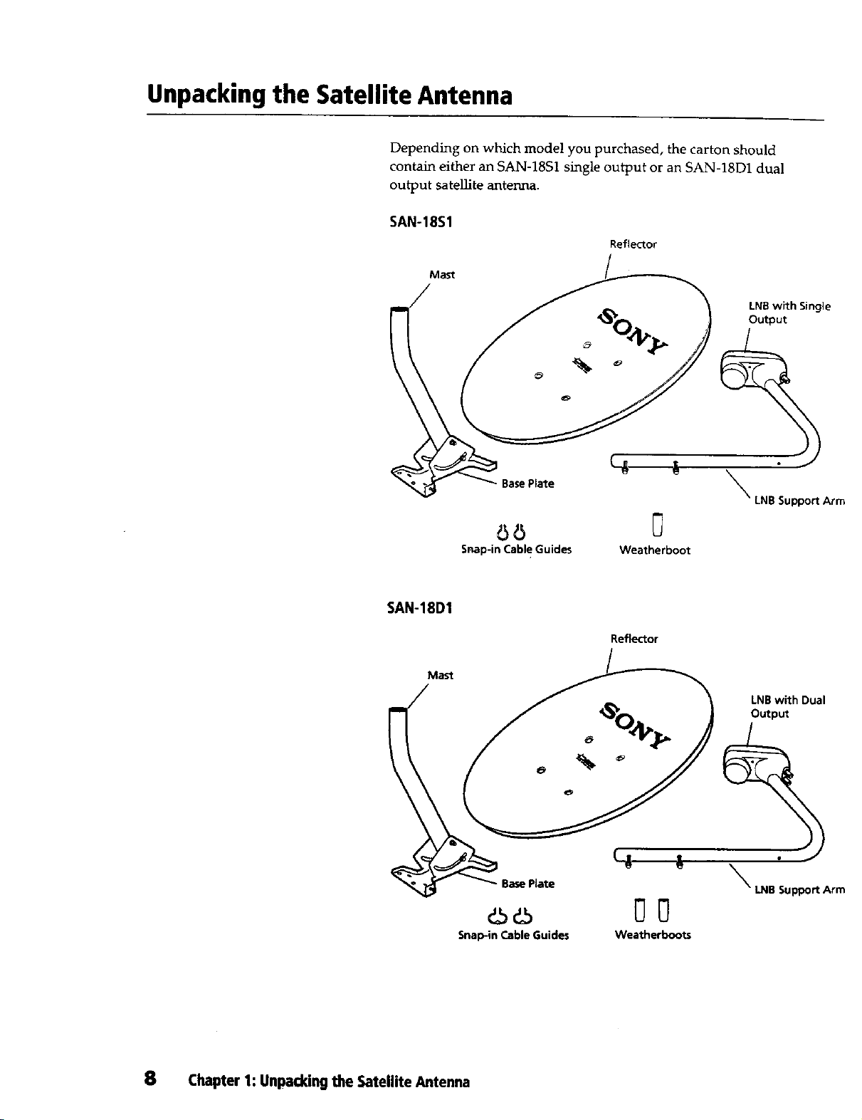
Depending on which model you purchased, the carton should
contain either an SAN-18S1 single output or an SAN-18D1 dual
output satellite antenna.
SAN-18S1
Mast
Reflector
LNB with Single
Output
SAN-18DI
Mast
BasePlate
O0
Snap-in Cabl e Guides
Base Plate
dSd5
Snap-in Cable Guides
\
LNB Support Arm
0
Weatherboot
Reflector
LNB with Dual
Output
\
LNB Support Arm
O0
Weatherboots
8 Chapter 1: Unpacking the Satellite Antenna
Page 9
Selecting an
Antenna Location
This chapter contains instructions for selecting a location to install the
satellite antenna.
The sections covered in this chapter are:
[3 Locating the SateLlite 10
Q Choosing an Installation Site 13
Page 10
Locating the Satellite
Notes
* At this stage it is not necessary tofind
the exact location of the satelIite. A
rough estimate is sufficient.
• The satellite is located due south of
Texas over the equator.
• The azimuth is a compass heading.
Before you can select a location to install the antenna, you need to find
the direction and elevation of the satellite relative to your house.
After you know where the satellite is located, you can find a suitable
location to install the antenna. Use the following instructions to
identify the directional coordinates and locate the satellite.
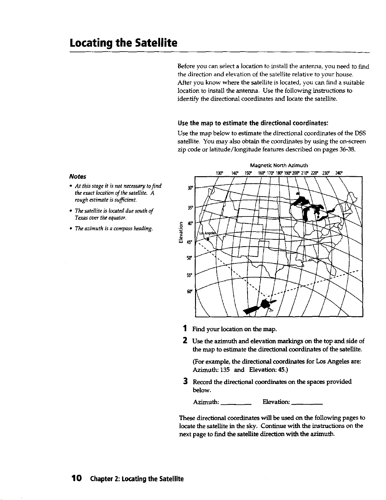
Use the map to estimate the directional coordinates:
Use the map below to estimate the directional coordinates of the DSS
satellite. You may also obtain the coordinates by using the on-screen
zip code or latitude/longitude features described on pages 36-38.
Magnetic North Azimuth
130" 140" 150' 160_170' 180_190"200_210"220_ 230' 240'
30"
35'
c 4_
._o
>
u_ 45o
5_
1 Find your location on the map.
2 Use the azimuth and elevation markings on the top and side of
the map to estimate the directional coordinates of the satellite.
(For example, the directional coordinates for Los Angeles are:
Azimuth: 135 and Elevation: 45.)
3 Record the dixectional coordinates on the spaces provided
below.
Azimuth: Elevation:
These directional coordinates will be used on the following pages to
locate the satellite in the sky. Continue with the instructions on the
next page to find the satellite direction with the azimuth.
10 Chapter 2: Locating the Satellite
Page 11
Note
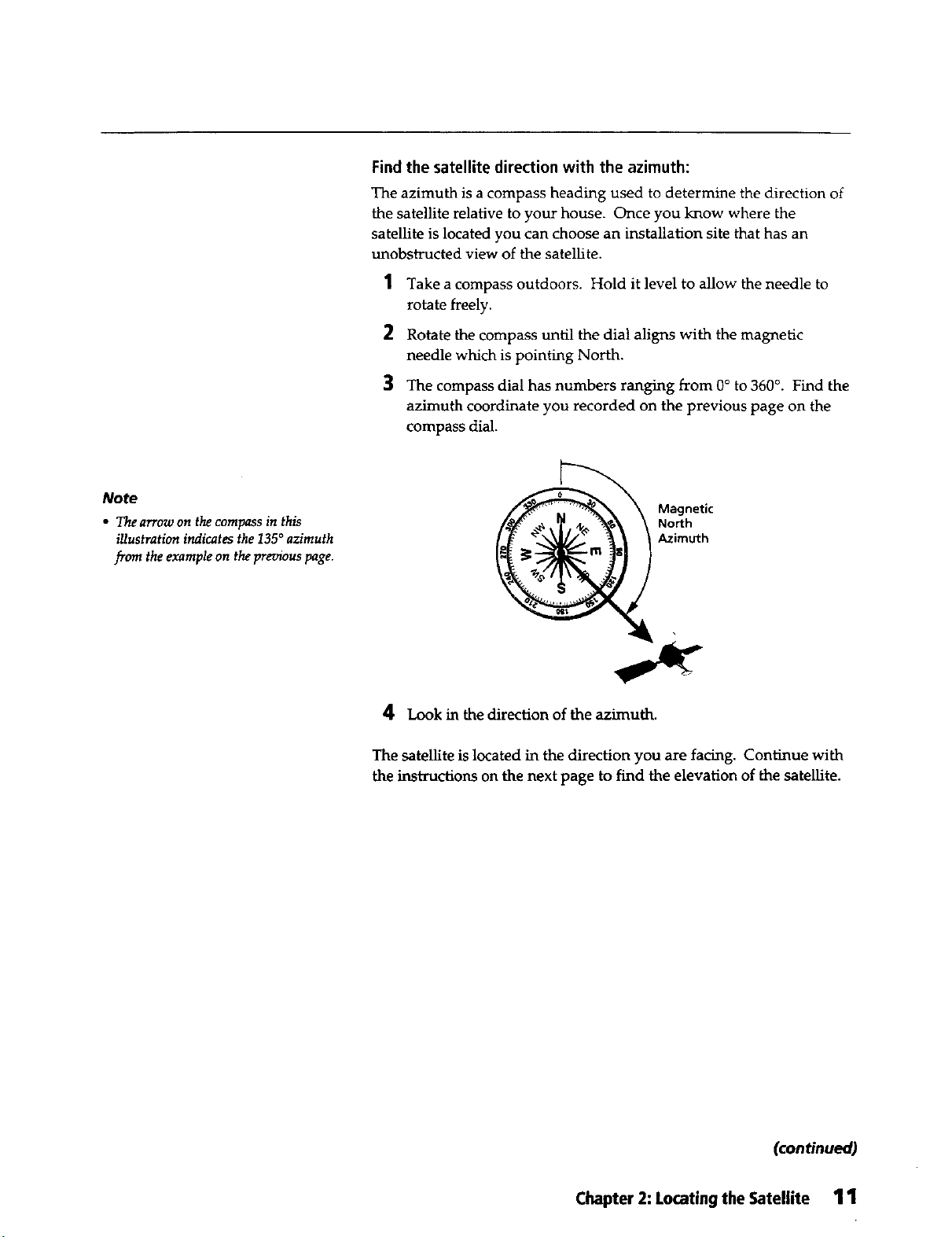
• The arrow on the compass in this
illustration indicates the 135 ° azimuth
from the example on the previous page.
Find the satellite direction with the azimuth:
The azimuth is a compass heading used to determine the direction of
the satellite relative to your house. Once you know where the
satellite is located you can choose an installation site that has an
unobstructed view of the satellite.
1 Take a compass outdoors. Hold it level to allow the needle to
rotate freely.
2 Rotate the compass until the dial aligns with the magnetic
needle which is pointing North.
3 The compass dial has numbers ranging from 0° to 360°. Find the
azimuth coordinate you recorded on the previous page on the
compass dial.
Azimuth
4 Look in the direction of the azimuth.
The satellite is located in the direction you are facing. Continue with
the instnlctions on the next page to find the elevation of the satellite.
(continued)
Chapter 2: Locating the Satellite 11
Page 12
Locating the Satellite (continued)
Find the elevation of the satellite:
Use the elevation coordinate you recorded on page 10 to find the
elevation of the satellite. Finding the elevation, or angle, of the
satellite enables you to choose an installation site that has an
unobstructed view of the satellite.
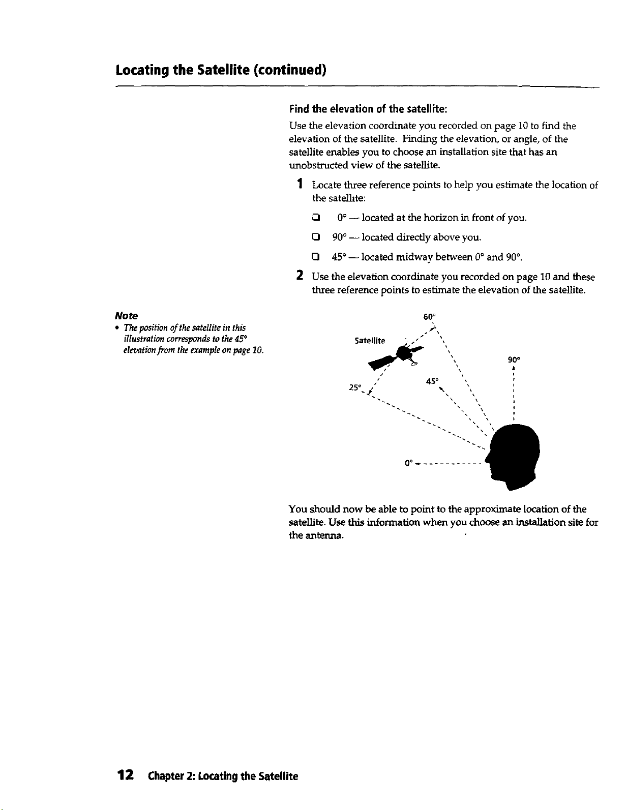
1 Locate three reference points to help you estimate the location of
2 Use the elevation coordinate you recorded on page 10 and these
the satellite:
121 0° -- located at the horizon in front of you.
D 90 ° -- located directly above you.
CI 45° -- located midway between 0° and 90°.
three reference points to estimate the elevation of the satellite.
Note
• The position o.fthe satellite in this
illustration corresponds to the 45°
elevation from the example on page 10.
60°
Satellite " .-
',
45 °
90"
2s°-_'.. ".,
\
\
0 a _
You should now be able to point to the approximate location of the
satellite. Use this information when you choose an installation site for
the antenna.
12 Chapter2: Locatingthe Satellite
Page 13
Choosing an Installation Site
You now know where the satellite is located in the sky. Keep the
location in mind as you look around your property for a good place to
install the antenna. Use the following suggestions to ease the
installation and extend the life of the antenna:
o
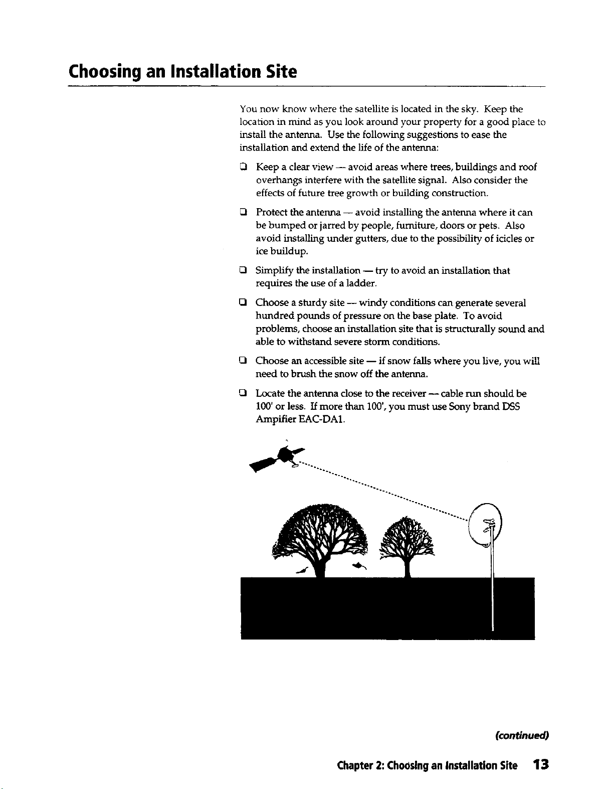
Keep a clear view -- avoid areas where trees, buildings and roof
overhangs interfere with the satellite signal. Also consider the
effects of future tree growth or building construction.
0
Protect the antenna -- avoid installing the antenna where it can
be bumped or jarred by people, furniture, doors or pets. Also
avoid installing under gutters, due to the possibility of icicles or
ice buildup.
0
Simplify the installation -- try to avoid an installation that
requires the use of a ladder.
O
Choose a sturdy site -- windy conditions can generate several
hundred pounds of pressure on the base plate. To avoid
problems, choose an installation site that is structurally sound and
able to withstand severe storm conditions.
0 Choose an accessible site -- if snow falls where you live, you will
need to brush the snow off the antenna.
0 Locate the antenna close to the receiver -- cable run should be
100' or less. If more than 100', you must use Sony brand DSS
Ampifier EAC-DA1.
(continued)
Chapter2: Choosingan InstallationSite 13
Page 14
Choosing an Installation Site (continued)
Where to Install the Antenna
This manual provides instructions for installing the antenna on
several surfaces:
Metal Pole
Q Wood
Brick
Q Cinder Block
Read through the rest of the manual before you begin installing the
antenna. Planning the installation will save you time and help you
avoid mistakes.
14 Chapter 2: Choosing an InstallaUon Site
Page 15
Installing the Antenna
This chapter provides instructions for installing, aiming and
grounding the antenna.
The sections covered in this chapter are:
_1 Installing the Mast or a Pole 16
Installing the Antenna 31
Q Installing the Cables 33
Aiming the Antenna 36
_1 Grounding the Antenna and Cables 43
Page 16
Installing the Mast or a Pole
This section contains four different sets of installation instructions.
Choose and follow one set, depending on the type of surface on which
you install the antenna:
UI Metal Pole, on this page.
Q Wooden Surface, on page 19.
Q Brick Surface, on page 24.
Q Cinder Block Surface, on page 27.
Metal Pole
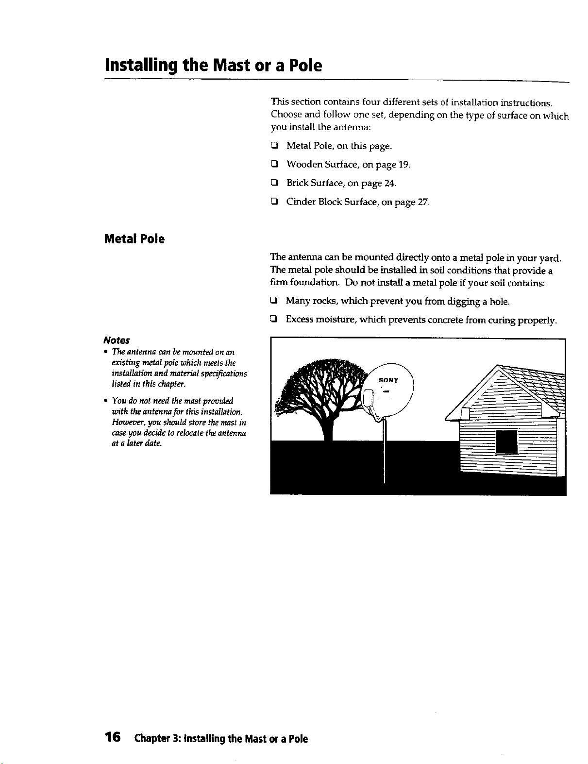
The antenna can be mounted directly onto a metal pole in your yard.
The metal pole should be installed in soi! conditions that provide a
firm foundation. Do not install a metal pole if your soil contains:
Q Many rocks, which prevent you from digging a hole.
Q Excess moisture, which prevents concrete from curing properly.
Notes
• Th_ antermcl can be mounted on an
existing metal polewhich meetsthe
installationand materialspecifications
listed in this chapter.
• You do not need the mast provided
with the antenna for this installation.
However, you should store the mast in
case you decide to relocate the antenna
at a later date.
16 Chapter 3: Installing the Mast or a Pole
Page 17
Tools and materials needed for this installation:
I brick
2 bags ready-mix cement
Container to mix cement
Guy wires/wooden stakes
Hacksaw
Level
Metal pole (6' long rain. x 11/4"- 11/2" galvanized steel pipe)
Shovel
>Warning
• Do not install the antenna near power lines.
>'Caution
• Avoid underground electric, telephone, gas, water and sewer lines when
digging in your yard. Contact your local utility companiesfor help locating
underground utility lines.
• Do not install the antenna where it could be bumped or jarred by people,
furniture, doors or pets.
• Do not attempt any installation in rainy or windy conditions.
Note
• Burythe pole6"belowthefrost lineif
youlive in anareathat experiences
freezing temperatures.
Installation instructions:
1 Dig a hole at least 8"in diameter and 36" deep.
2 Cut the bottom of the pole at a 45° angle with a hacksaw. This
prevents the pole from rotating after installation.
(continued)
Chapter 3: Installing the Mast or a Pole 17
Page 18

Installing the Mast or a Pole (continued)
3
Place a stone or brick at the bottom of the hole. The 45° cut on
the bottom of the pole should sit on top of the stone or brick.
This allows the cement to cover the angled cut.
/ MetalPole
36"
Min.
Note
• Stop pouring the c_nent three inches
below the top of the hole if you intend
to cover the cement with dirt or replant
grass after the cement has dried.
4 Mix ready-mix cement and pour it into the hole.
5 Hold the pole upright and level it with a bubble level. Place the
level along the side of the pole and take at least two readings 90°
(at right angles) from each other. The pole must be vertically
level to aim the antenna properly.
. _Metal Pole
90o'_ _- Level the Pole
"_, at Right Angles
Side View Top View
6 Secure the pole with guy wires or wooden braces while the
cement is drying.
7 Check to make sure the pole is still level and adjust if necessary.
8 Wait for the cement to dry completely before you remove the
guy wires or wooden braces.
Proceed to Installing the Antenna on page 31.
18 Chapter3: Installingthe Mast or a Pole
Page 19

Wooden Surface
The satellite antenna can be installed on a variety of wooden surfaces.
This section provides instructions for mounting the mast onto the
following:
Side of your house
Installation on aluminum or
vinyl siding not recommended.
Deck railing or floor
Roof
Installation on wooden roof and
rafter under asphalt shingles
only.
Do not install the antenna on composite materials unless a wall stud
or rafter can be located behind the surface. These wood products are
not strong enough by themselves to secure the antenna properly. The
materials to avoid are:
Q Strand Board
rl Chip Board
Q Fiberboard
Particleboard
(continued)
Chapter 3: Installing the Mast or a Pole 19
Page 20

Installing the Mast or a Pole (continued)
Tools and materials needed for this installation:
Drill bits (1/8", 3/ld')
*Lag screws (2) 1/4"x 3", (4) s/_d' x 2"
Level
Pencil/chalk
Power drill
*Silicon sealant
Tape measure
*Washers (4)s/16"
Wrench (3/8")
*Includedin the Installation Kit.
>Warning
• Do not install the antenna near power lines.
>.Caution
• DOnot install the antenna where it could be bumped or jarred by people,
furniture, doors or pets.
• Do not attempt any installation in rainy or windy conditions.
Installation instructions:
1 Choose a secure location to install the base plate:
UI Side of your house -- find a wall stud on which you can
secure the base plate. Wall studs can be located by a vertical
line of nails where siding is attached to the house, or with a
stud finder.
Outside Holes
(4) 5/16"x 2"
Lag Screws
Wooden Shim (for
Center Holes
(2) 1/4"x3"
LagScrews
Siding only)
20 Chapter 3: Installing the Mast or a Pole
Page 21

Deck railing or floor -- the base plate can be secured to the
railing or floor.
Outside Holes
(4) 5/16"x 2"
Lag Screws
Roof -- find a rafter on which you can install the base plate.
Rafters can be located by the nails which hold the fascia board
onto the rafters. Do not mount the mast on a roof overhang
where there are no rafters.
Outside Holes
(4) 5/16"x 2"
Lag Screws
to Roof Pitch
Center Holes N,
(2) 1/4"x 3"
Lag
parallel
Fascia /_
Board
Transfer
Measurement
to Roof
2
Position the two center holes of the base plate over a stud or
rafter, and hold the base plate in position.
/ Stud or Rafter
I _'/ Center Hole
1_ / Outside Hole
Ho,e I;;I
I I
I I
(continued)
Chapter 3: Installing the Mast or a Pole 21
Page 22

Installing the Mast or a Pole (continued)
Use a level to determine whether the mast can be vertically
aligned before you drill any holes.
A) Loosen the pivot bolt and adjustment nut that connect the
bottom of the mast to the base plate and align the mast in a
vertical position.
B) Place the level along the top part of the mast and take two
readings 90° apart from each other.
C) Tighten the pivot bolt and adjustment nut.
D) Use wooden shims to correct any alignment problems. If
shims will not correct the problem, look for another location
to mount the antenna.
Level
. Mast
Pivot Bolt
Side View
Adjustment
Nut
(ea. side)
, Mast
"90o_ Level the Mast
--1, at Right Angles
Top View
22 Chapter 3: Installing the Mast or a Pole
Page 23

4 Realign the top center hole of the base plate over the stud, frame
or rafter and mark with a pencil.
S Remove the mast and drill a _/8" x 3" pilot hole.
6 Reposition the mast and attach it with a _/4" x 3" lag screw. Do
not tighten too securely to allow for adjustment.
7 Check to make sure the mast is still level and adjust if necessary.
8 Mark the remaining four outside holes and the lower center hole.
9 Remove the base plate and drill pilot holes for the remaining
screws:
O Four outside holes -- drill 3/16"x 2" holes.
O Lower center hole -- drill a 1/8" x 3" hole.
10 Apply silicon sealant to all six pilot holes and around the bottom
edge of the base plate where it makes contact with your house
before bolting it down tight. This will prevent water seepage.
IL_ Stud or Rafter
I
Sealant
11 Bolt the base plate into position using:
O Four outside holes -- s/16"x 2" lag screws and 5/16"washers.
O Two canter holes -- 1/4,,x 3" lag screws.
Proceed to Installing the Antenna on page 31.
(continued)
Chapter 3: Installing the Mast or a Pole 23
Page 24

Installing the Mast or a Pole (continued)
Brick Surface
The satellite antenna can be installed on brick surfaces. This section
provides instructions on how to mount the mast onto the following:
Q Side of your house
Q Wall
Note
• Thedoubleexpansionanchorsyou
shouldbeable towithstand 300
pounds ofpull-out pressure.
Tools and materials needed for this installation:
*Double expansion anchors (4)
Hammer
Level
*Machine screws (4) 1/4" - 20 x 3"
Masonry drill bit (1/2")
Pencil
Power drill
*Washers (4) s/16"
Wrench Gls")
*Included in the Installation Kit.
Warning
• Do not install the antenna near power lines.
).Caution
• Do not install the antenna on stucco or imitation masonry unless the base
is made of cinder block or brick.
• Do not install the antenna where it could be bumped or jarred by people,
furniture, doors or pets.
• Do not attempt any installation in rainy or windy conditions.
24 Chapter3: Installing the Mast or a Pole
Page 25

Installation instructions:
1
Choose a flat and secure location to install the antenna and hold
the base plate in position,
2
Position the four outer holes of the base plate over the surface of
the bricks. Do not drill into the mortar around the bricks.
Outside Holes
(4) 1/4"- 20 x 3"
Machine Screw_
RelativelyFlat
Sun'ace
3 Use a level to determine whether the mast can be vertically
aligned before you drill any holes.
Level
Nuts
(ea. side)
90o'X_ _ Level the Mast
-1 at Right Angles
Side View Top View
A) Loosen the pivot bolt and adjustment nuts which connect
the bottom of the mast to the base plate and align the mast in
a vertical position.
B) Place the level along the top part of the mast and take two
readings 90=apart from each other.
C) Tighten the pivot bolt and adjustment nuts.
(continued)
Chapter 3: Installing the Mast or a Pole 25
Page 26

Installing the Mast or a Pole (continued)
4 Mark the upper left hole of the base plate with a pencil.
5 Remove the mast and drill a _/f' x 3" hole.
6 Clean out the hole and insert a double expansion anchor, It
should fit snugly. Use a hammer to gently tap the anchor into
place until it is flush with the wall.
7 Use a 1/4"- 20 x 3" machine screw to attach the base plate to the
anchor. Do not tighten too securely to allow for adjustment.
8 Check to make sure the mast is still level.
Brick Surface
3" Depth
(mini
Double
Anchor
Brick Side View
Note
• It is not necessary to bolt the two
center holes in this procedure.
9 Mark the remaining three outer holes, and repeat steps 5
through 8.
10 Tighten all four screws.
Proceed to Installing the Antenna on page 31.
26 Chapter 3: Installing the Mast or a Pole
Page 27

Cinder Block Surface
The satellite antenna can be installed on cinder block surfaces. This
section provides instructions on how to mount the mast onto the
following:
Side of your house
o Wall
i ¸ ' ... .i
Tools and materials needed for this installation:
You will need the following tools and materials for this installation:
Hammer
Level
*Machine screws (4) '/4" - 20 x 3"
Masom'y drill bit (1/2")
Pencil
Power drill
*Togglers (4)
*Washers (4) Vi'
Wrench (3/8")
*Included in the Installation Kit.
_.Wamin9
• Do not install the antenna near power lines.
_Caution
• Do not install the antenna where it could be bumped or jarred by people,
furniture, doors or pets.
• Do not attempt any installation in rainy or windy conditions.
(continued)
Chapter 3: Installing the Mast or a Pole 27
Page 28

Installing the Mast or a Pole (continued)
Installation instructions:
1 Choose a flat and secure location to install the antenna.
2 Tap the cinder blocks with a hammer to find the hollow center
cores.
16" Three Core 16_ Two Core 8" Two Core
3 Position the four outer holes of the base plate over the hollow
center cores of the cinder block and hold the base plate in
position.
28 Chapter 3: Installing the Mast or a Pole
Outside Holes
(4) 1/4"- 20 x 3"
Machine Screws _"
Page 29

4 Use a level to determine whether the mast can be vertically
aligned before you drill any holes.
Level
' Mast
Jstment
Nuts
(ea. side)
-_ Level the Mast
_ at Right Angles
Side View Top View
A) Loosen the pivot bolt and adjustment nuts that connect the
bottom of the mast to the base plate and align the mast in a
vertical position.
B) Place the level along the top part of the mast and take two
readings 90° apart from each other.
Note
• Fill mistakes with mortar or silicon
sealant.
C) Tighten the pivot bolt and adjustment nuts.
5 Mark the upper left hole of the base plate with the pencil.
6 Remove the mast and drill a l/f, hole.
7 Install a toggler.
A) Fold the metal channel fiat against the toggler and insert it
into the hole until the channel opens.
Fold in
!" Drill Thru
Toggler Metal Channel
(continued)
Chapter 3: Installing the Mast or a Pole 29
Page 30

Installing the Mast or a Pole (continued)
Note
• The toggler must lie completelyflat
against the inside of the cinder block
to be effective.
B) Pull the toggler toward you to apply tension while sliding
the plastic cap until it is snug against the wall.
Block Wall
Ring _'_
Plastic Cap
C) Break the ring along the center perforation and push the
two halves away from each other. Push them toward the
wall until they break at the plastic cap.
Break
8 Use a 1/4" - 20 x 3" machine screw to attach the mast to the cinder
block. Do not tighten the screw too securely to allow for
adjustment.
9 Check to make sure the mast is still level.
10 Mark the remaining three outer holes, and repeat steps 6through 9.
11 Tighten all four bolts.
Proceed to Installing the Antenna on page 31.
30 Chapter 3: Installing the Mast or a Pole
Page 31

Installing the Antenna
Assembling the Antenna
This section contains instruchons for installing the antenna. There are
two procedures you need to complete:
Assembling the Antenna
[_ Mounting the Antenna on the Mast or Pole
Tools needed to install the antenna:
Phillips screwdriver
Assemble the antenna by bolting the LNB support arm onto the
reflector.
Reflector Bracket _ __
"
1 Place the end of the LNB support arm against the back of the
reflector bracket and align the two screw holes.
2 Screw the two machine screws in the LNB support ann into the
reflector brackotandtight_ evenly (torque 36-45 lb-in). Do not
overtighten.
The antenna is assembled and is now ready to be mounted on the
mast or pole you installed earlier.
(continued)
Chapter 3: Installing the Antenna 31
Page 32

Installing the Antenna (continued)
Mounting the Antenna on the
Mast or Pole
Mount the antenna by attaching the pre-assembled mast clamp on the
reflector to the mast or pole.
Reflector Bracket
Metal Stop _
Mast Clamp
Note
• Remove the metal stop to mount the
antenna below the top of a metal pole.
Make sure the antenna tilts freely
before securing the bolts.
32 Chapter 3: Installing the Antenna
1 Loosen the two screws that attach the mast clamp to the reflector
bracket.
2 Lower the antenna onto the mast or pole until it rests against the
metal stop.
3 Tighten the two clamp screws evenly. Do not over tighten
because they will need to be loosened when you aim the
antenna.
The antenna is now in place and is ready to have cables attached.
Follow the instructions in the next section to install the cables.
Page 33

Installing the Cables
This section contains instructions for installing cables which connect the
antenna to the receiver. There are two procedures you need to complete:
Q Connecting the Antenna to the Grounding Block
UI Connecting the Grounding Block to the Receiver
Tools and materials needed to install the cables:
Cable clips (8)
Cable ties (4) 1t"
Drill bit (s/d)
*Grounding block
Phillips screwdriver
Power drill
*RG-6 coaxial cables (25 ft., 75 ft.)
*Silicon sealant (1 oz.)
*Included in the Installation Kit.
.Connecting the Antenna to the
Grounding Block
Notes
• RG-6coax_l cablemust be used.
Othercablesmay reducesignalquality
and signal strength.
• Attach separate cablesto bothLNB
connectorsifyou installedthe SAN-
18D1 satelliteantenna.
The antenna is connected to the receiver with two RG-6 coaxial cables.
The first cable you install connects the antenna to the grounding block
at the side of your house.
1 Attach an RG-6 coaxial cable with a weatherproof rubber boot to
the LNB (torque 18 lb-in). The weatherproof boot should fit
snugly against the LNB.
LNB
Weatherboot
RG-6 Coaxial Snap-in
Cable Cable Guides
Rain Hole
2 Secure the cable to the LNB support arm with two snap-in cable
guides. Attach the guides to the cable at positions opposite the
holes on the LNB support arm.
(contJnued)
Chapter 3: Installing the Cables 33
Page 34

Installing the Cables (continued)
3 Take up any slack in the cable before pressing the snap-in cable
4 Use cable ties to secure the cable to the mast or metal pole.
5 Install a grounding block onto the side of your house. The
Notes
• The connectors you attach to the
grounding block should be waterproof
type.
• Protect exposed terminals by wrapping
them in tape.
guides into the holes. Begin at the LNB and work your way
toward the mast or pole.
grounding block should be installed on the exterior wall of the
room where the receiver will be located.
_i Coaxial Cable Mounting Screw
Block
Note
• Drip loops prevent water from leaking
into the grounding block.
6 Route the cable from the antenna to the grounding block. Take
the most direct route and avoid these problems:
[_ Do not place the cable where it can be damaged by lawn
mowers, people or pets.
Q Do not bend the cable beyond its normal flexib'flity.
[_ Do not sever the cable or the cable insulation.
D Do not use anything other than RG-6 coaxial cable.
7 Use cable clips to make a four to six inch diamet_ drip loop at
the end of the cable.
8 Tightly screw the cable from the antenna onto one of the
grounding block terminals.
/ From Antenna
Grounding Block
34 Chapter 3: Installing the Cables
Page 35

Connecting the Grounding Block
to the Receiver
Connect the grounding block to the receiver with RG-6 coaxial cable
to complete the cable installation.
>_Caution
• Be careful to avoid drilling into electrical, water or gas utility lines.
Notes
• The connectors you attach to the
grounding block should be waterproof
type.
1 Tightly screw one end of an RG-6 coaxial cable into the
grounding block terminal across from the one you connected to
the antenna.
2 Use cable clips to make a four to six inch diameter drip loop.
j From Antenna
5/8" Drill Thru- __=
To Receiver
Drip Loop / Grounding
Block
3 Drill a s/8" hole through the exterior wall near the spot where
the receiver will be located.
4 Wrap the end of the cable with tape to protect the center
conductor and feed it through the wall into your house.
Note
• You can install a wall plate inside
your house at this time to give the
installation a finished look.
5 Unwrap the tape and check the connector to be sure the center
conductor is straight and undamaged..
6 Pull enough cable into the room to reach the back of the receiver.
7 Seal the hole around the cable with silicon sealant.
The antenna and cable are now completely installed. Read the next
section to learn about aiming the antenna.
Chapter 3: Installing the Cables 35
Page 36

Aiming the Antenna
Connecting the Antenna to the
Receiver
Note
• This isa temporary connection which
allows you to view the receiver's on-
screen displays. Refer to the Sony
Distal Satellite Receiver operating
instructions for complete connection
information.
This section contains instructions for aiming the antenna. There are
four procedures you need to complete:
Connecting the Antenna to the Satellite Receiver
Q Pointing the Antenna
Q Fine-tuning the Antenna Using the Signal Seeker TM
Fine-tuning the Antenna Using the Signal Strength Meter
Tools needed to aim the antenna:
Wrench (s/s")
or
Phillips screwdriver
Connect the antenna to the satellite receiver to fine-tune the aim of
the antenna.
1 Turn off both the TV and _ceiver, and unplug the receiver's AC
cord.
2 Connect the RG-6 coaxial cable from the satellite antenna to the
SATELLITE IN jack on the back of the receiver.
RG-6CoaxialCable
FromSatelliteAntenna
36 Chapter3: Aiming the Antenna
II @ II ._ T'-n=@"
illllllllt! -"='-., , , ! -.,..-
--- • :-:': o%-
o t
ToTV
CoaxialCable l
AC Cord L
Satellite Receiver
3 Connect a cable from the VI-ff: (SAT)/UI-IF OUT jack on the back
of the l_ceiver to the UHF/VHF jack on the back of your TV.
4 Plug in the receiver's AC cord, and turn on both the TVand receiver.
S Tune the TV to channel 3 or 4 to match the setting of the CH3/
CH4 switch on the back of the receiver.
Page 37

Note
• Press TV/DSS and confirm that the
DSS indicator on the receiver is lit.
6 Press DSS FUNCTION on the receiver remote control.
%©0
_ _ D,_
O CD_
7
Press MENU on the remote control to display the MAIN MENU
screen. _y @ E(_
8 Select SYSTEM MENU. Press the tt and _,, and the * and *
buttons on the remote contro! to highlight, and press -4- to select
SYSTEM MENU.
MAIN MENU
11SELECI"
SELECT IMASI1ER
_",DE 1 GUIDE
MOVIES
_m 4 IExrr
Ol!tER [CUSTOM
GU DES 7 GUIDE
2/Iu_ 3
lIMO.Es I
511usT 61
9 Sele<
10 Select SET UP ANTENNA.
tINSTALLATION MENU.
INSTALLATION MENU
[ ] AII_sCEcARD 2
[
cont_ued)
Chapter3: Aimingthe Antenna 37
Page 38

Aiming the Antenna (continued)
Note
• You may also get your azimuth and
elevation coordinates by selecting
LA T/LONG, and inputting your
longitude and latitude coordinates.
11
12 Enter your zip code by using the 0 - 9 buttons. Your azimuth
Select ZIPCODE.
SETUP ANTENNA
D_mil_ the azimuth and elevation and d_ the tiEAlal _.
'L °llIJlltlitltllPlllltlllllll
A
and elevation will appear at the bottom of the screen. Select
RETURN.
ENTERZIP CODE
Useyour _ codeto he_ locke Ute _mtrth andelev.-tJcm,
nBDnD
Note
• The azimuth and elevation for
Los Angeles are repre.-_mted in this
illust_tian.
A_'nmll_l 137 _ EleYa*_of146 degrees
13 Your azimuth and elevation are also displayed at the bottom of
the SET UP ANTENNA screen. Above the azimuth and
elevation is the Signal Strength Meter you will use to fine-hzne
the aim of the antenna.
SET UP ANTENNA
,u..FT'Ti
This is the screen you use to point and fine-tune the antenna in
the following sections.
38 Chapter 3: Aiming the Antenna
Page 39

Pointing the Antenna
Note
• Theposition oftheantenna in this
illustration corresponds to the 45 °
elevation from the example on page 10.
Point the antenna toward the satellite using the azimuth and elevation
headings displayed in the ZIP CODE or SET UP ANTENNA screen,
described on page 38.
1 Loosen the four adjustment bolts on the back of the antenna.
2 Set the elevation pointer to the correct elevation heading.
ustment
Bolts
(ea. side) Elevation
Pointer
3 Secure the bolts but do not overtighten; you will need to loosen
them later to fine-tune the antenna.
Note
• Use the compass toJind the antenna
heading.
4 Loosen the two mounting bolts that hold the antenna onto the
mast or pole.
5 Point the antenna toward the correct azimuth heading.
Bolts
(continued)
Chapter3: Nming theAntenna 39
Page 40

Aiming the Antenna (continued)
Note
• The antenna will appear to point
below where the satellite is located.
Do not re-adjust the antenna.
6 Secure the bolts but do not overtighten; you will need to loosen
them later to fine-tune the antenna.
Fine-tuning the Antenna Using
the Signal Seeker
Note
* TheSignal Seekerwill only work when
the on-screensignalstrength meter is
displayedon your TV.
The strength of the signal received from the satellite should be
optimized. If the signal gets too weak, the picture will freeze. Rain
and snow can reduce the signal strength, so optimizing the signal
strength will help to eliminate their affect. Use the Signal Seeker to
fine-tune the aim of the antenna. The Signal Seeker light blinks slowly
when the antenna is receiving a weak signal and blinks faster as the
signal grows stronger.
LNB _ Signal Seeker
1 To fine-tune the azimuth, loosen the two mounting bolts that
hold the antenna on the mast or pole.
40 Chapter 3: Aiming the Antenna
Page 41

2 Slowly move the antenna from side-to-side until the Signal
Seeker gives the fastest blink.
Mounting
Bolts Signal Seeker
3 Secure the bolts but do not overtighten; you will need to loosen
them later to further fine-tune the antenna.
4 To fine-tune the elevation, loosen the four adjustment bolts on
the back of the antenna.
5 Gently tilt the antenna up and down until the Signal Seeker gives
the fastest blink.
Adjustment
Bolts (ea. side)
r J
Signal Seeker
6 Secure the bolts but do not overtighten; you will need to loosen
them later to further fine-tune the antenna.
7 Fine-tune the azimuth once again using steps 1-3.
Chapter 3: Aiming the Antenna 41
(continued)
Page 42

Aiming the Antenna (continued)
Fine-tuning the Antenna Using
the Signal Strength Meter
Complete the aiming procedures by fine-tuning the antenna using the
Signal Strength Meter. The on-screen display shows a numeric value
for the signal strength ranging from 0 to 100. A reading of 0 indicates
no signal is being received and a reading of 100 is the strongest
possible signal. To use the Signal Strength Meter, you can:
Q Have someone watch the on-screen signal meter and call out the
Q Position the TV so you can see the screen from the antenna.
Notes
• Adjust the signal to its peaklevel to
minimizesignalloss due to rainor
snow.
• YOuprobably wil! not receive a signal
strength of lO0. Different areas of the
country may receive different peak
levels. This is normal.
signal strength level while you adjust the antenna.
"l Adjust the azimuth by loosening the two mounting bolts that
secure the antenna to the mast or pole.
2 Slowly move the antenna side to side until you find the strongest
signal.
3 Tighten the mounting bolts (torque 36--45 lb.-in)
4 Adjust the elevation by loosening the four adjustment bolts on
the back of the antenna.
5 Slowly tilt the antenna up and down until you find the strongest
signal.
6 Tighten the adjustment bolts (torque 36,--45 [bSin)
I SET UP ANTENNA
0
A
The antenna is now installed and properly adjusted to receive satellite
signals. The final step in the installation process is grounding the
antenna and grounding block.
42 Chapter 3: Aiming the Antenna
Page 43

Grounding the Antenna and Cables
This section contains instructions for grounding the antenna and
cables to prevent possible damage from electrical charges and nearby
lightning strikes. Refer to the National Electrical Code m the
Appendix for more specific information on grounding requirements.
There are two procedures you need to complete:
Grounding the Antenna
Grounding the Cables
Tools and materials needed to ground the antenna and cables:
Grounding rod (8 ft.)
*Grounding strap
*Grounding wire (30 ft.)
Ladder
Phillips screwdriver
Sledgehammer
*Included in the Installation Kit.
Grounding the Antenna
Ground the antenna to protect it from possible damage from
unwanted electrical charges.
From Base
Plate
Grounding Wire
Grounding
Grounding Rod
1 Install a grounding rod as close to the mast or pole as possible.
The rod should be 8 feet long and driven 8 feet into the ground.
Any deviation from these specifications should conform to the
National Electrical Code and local code requirements.
(_ontlnue¢@
Chapter3: Groundingthe Antennaand Cables 43
Page 44

Grounding the Antenna and Cables (continued)
2 Locate the grounding point on the mast or metal pole. On the
mast, the grounding point is located on the mounting foot. On
the metal pole, the grounding point is a grounding strap you
attach to the base of the pole.
Metal P°le .'_-_._T
Grounding Wire \ -II ....
Grounding Strap \ \ II /
Grounding Rod ! ___
\ [I / _rounotng _trap
Grounding Screw
Gt'ounding
Metal Pole
Mounting Foot
3 Attach one end of a #10 copper grounding wire to the mast or
pole by looping the bare wire two turns around the grounding
screw or grounding strap.
4 Tighten the screw or strap until the wire is secure.
5 Route the other end of the grounding wire to the grounding rod
in a straight and direct path.
6 Connect the grounding wire to the grounding rod using a
grounding strap. Install the strap above ground unless it is
designed for underground use.
Complete the grounding procedure by grounding the cables.
44 Chapter3: Groundingthe Antennaand Cables
Page 45

Grounding the Cables
Ground the cables to protect the receiver from possible damage from
unwanted electrical charges.
RG-6 Coaxial
Grounding
Block _ _
Grounding _
Wire
Grounding Strap _ -_
Grounding Rod _'_
Cable \
/ 5/8" Drill Thru
8'
Notes
• Thecablesandantenna canbe
groundedon thesamegrounding rod.
• Thegrounding wire shouldbeshort
andstraight. Connectit closeto
whereit enters the house.
I ]mtan a grounding rod as close to the grounding block as
possible. The rod should be 8 feet long and driven 8 feet into the
ground. Any deviation from these specifications must conform
to the National Electrical Code and local code requirements.
2 Attach a #10 copper grounding wire to the grounding block by
inserting one end of the bare wire into the grounding wire
terminal and tightening the screw until the wire is secure.
Grounding Wire
on Wire
3rounding Block
(continued)
Chapter3: Groundingthe AntennaandCables 45
Page 46

Grounding the Antenna and Cables (continued)
Note
• The grounding block may also be
grounded to a cold water pipe. Refer
to the National Electrical Code in the
Appendix.
3 Route the other end of the grounding wire to the grounding rod
in a straight and direct path.
4 Connect the grounding wire to the grounding rod using the
grounding strap, Install the strap above ground unless it is
designed for underground use.
From Antenna
jTo e e,ve
Or!uoO,ngW,re
_-_ Groundinc. Rod
_ Grounding Strap
8 L i_
If
Ii
I I
LI
I I
I
Congratulations! The antenna and cables are grounded and you have
completed the antenna installation. Refer now to the manual you
received with your Sony Digital Satellite Receiver to learn about
hooking up other components to your receiver.
46 Chapter 3: Grounding the Antenna and Cables
Page 47

Other Information
The sections covered in this appendix are:
0 National Electrical Code 48
0 Specifications 50
Limited Warranty 51
O Glossary 53
0 Index 55
Page 48

National Electrical Code
The following portions of the National Electrical
Code are provided to assist you with the installation of
your digital satellite antenna. These pages represent
only a portion of the entire National Electrical Code,
and should be consulted for reference purposes only.
For the complete code, please refer to the National
Electrica! Code Handbook.
250-1. Scope. This article covers general
requirements for grounding and bonding of electrical
installations, and specific requirements in (a) through
(f) below.
(a) Systems, circuits, and equipment required,
permitted, or not permitted to be grounded.
(b) Circuit conductor to be grounded on grounded
systems.
(el Location of grounding connections.
(d) Types and sizes of grounding and bonding
conductors and electrodes.
(e) Methods of grounding and bonding.
sections or insulating pipe) to the points of
connection of the grounding electrode conductor and
the bonding conductors. Continuity of the
grounding path or the bonding connection to interior
piping shall not rely on water meters. A metal
underground water pipe shall be supplemented by
an additional electrode of a type specified in Section
250-81 or in Section 250-83. The supplemental
electrode shall be permitted to be bonded to the
grounding electrode conductor, the grounded
service-entrance conductor, the grounded service
raceway, or any grounded service enclosure.
250-83. Made and Other Electrodes. Where none
of the electrodes specified in Section 250-81 is
available, one or more of the electrodes specified in
(b) through (d)* below shall be used. Where
practicable, made electrodes shall be embedded
below permanent moisture level. Made electrodes
shall be free from nonconductive coatings, such as
paint or enamel. Where more than one electrode is
used, each electrode of one grounding system
(including that used for lightning rods) shall not be
less than 6 feet (1.83 m) from any other electrode of
another grounding system.
(f) Conditions under which guards, isolation, or
insulation may be substituted for grounding.
250-81. Grounding Electrode System. If available
on the premises at each building or structure served,
each item (a) through (d) below, and any made
electrodes in accordance with Sections 250-83 (c) and
(d), shall be bonded together to form the grounding
electrode system. Interior metal water piping located
more than 5 feet (152 cm) from the point of entrance
to the building shall not be used as a conductor to
interconnect the electrodes and the grounding
electrode conductor. The bonding jumper shall be
installed in accordance with Sections 250-92 (a) and
(b), shall be sized in accordance with Section 250-94,
and shall be connected in the manner specified in
section 250-115. The uanspliced grounding electrode
conductor shall be permitted to run to any
convenient grounding electrode available in the
grounding electrode system. It shall be sized for the
largest grounding electrode conductor required
among all the available electrodes.
(a) Metal Underground Water Pipe. A metal
underground water pipe in direct contact with the
earth for 10 feet (3.05 m) or more (including any
metal well casing effectively bonded to the pipe) and
electrically continuous (ormade electrically
continuous by bonding around insulating joints or
(c) Rod and Pipe Electrodes. Rod and pipe
electrodes shall not be less than 8 feet (2.44 m) in
length and shall consist of the following materials,
and shall be installed in the following manner:
(1) Electrodes of pipe or conduit shall not be
smaller than 3/4 -inch trade size and, where of iron or
steel, shall have the outer surface galvanized or
otherwise metal-coated for corrosion protection.
(2) Electrodes of rods of iron or steel shall be at
least 5/s inch (15.87 mm) in diameter. Stainless steel
rods less than 5/8 inch (15.87 ram) in diameter,
nonferrous rods, or their equivalent shall be listed
and shall not be less than _/a inch (12.7 mm) in
diameter.
(3) The electrode shall be installed such that at
least 8 feet (2.44 m) length is in contact with the soil.
It shall be driven to a depth of not less than 8 feet
(2.44 m) except that, where rock bottom is
encountered, the electrode shall be driven at an
oblique angle not to exceed 45 degrees from the
vertical or shall be buried in a trench that is at least
21/2 feet (762 ram) deep. The upper end of the
electrode shall be flush with or below ground level
unless the aboveground end and the grounding
electrode conductor attachment are protected against
physical damage as specified in Section 250-117.
48 Appendix: Other Information
Page 49

250-115. Connection to Electrodes. The grounding
conductor shall be connected to the grounding
electrode by exothermic welding, listed lugs, listed
pressure connectors, listed clamps, or other listed
means. Connections depending on solder shall not be
used. Ground clamps shall be listed for the materials
of the grounding electrode and the grounding
electrode conductor and, where used on pipe, rod, or
other buried electrodes, shall also be listed for direct
soil burial. Not more than one conductor shall be
connected to the grounding electrode by a single
clamp or fitting unless the clamp or fitting is listed for
multiple conductors. One of the methods indicated
in (a), Co), (c), or (d)* below shall be used.
(a) Bolted Clamp. A listed bolted clamp of cast
bronze or brass, or plain or malleable iron.
(b) Pipe Fitting, Pipe Plug, etc. A pipe fitting, pipe
plug, or other approved device screwed into a pipe or
pipe fitting.
(c) Sheet-Metal-Strap Type Ground Clamp. A
listed sheet-metal-strap type ground clamp having a
rigid metal base that seats on the electrode and
having a strap of such material and dimensions that it is
not likely to stretch during or after installation.
810-1. Scope. This article covers radio and
television receiving equipment and amateur radio
transmitting and receiving equipment, but not
equipment and antennas used for coupling carrier
current to power line conductors.
(d) Mechanical Protection. The grounding
conductor shall be protected where exposed to
physical damage, or the size of the grounding
conductors shall be increased proportionately to
compensate for the lack of protection.
(el Run in Straight Line. The grounding conductor
for an antenna mast or antenna discharge unit shall
be run in as straight a line as practicable from the
mast or discharge unit to the grounding electrode.
(f) Electrode. The grounding conductor shall be
connected as follows:
(1) To the nearest accessible location on (1) the
building or structure grounding electrode system as
covered in Section 250-81, (2) the grounded interior
metal water piping system as covered in Section 250-
80(a), (3) the power service accessible means external
to enclosures as covered in Section 250-71(b), (4) the
metalic power service raceway, (5) the service
equipment enclosure, or (6) the grounding electrode
conductor or the grounding electrode conductor
metal enclosures; or
(2) If the building or structure served has no
grounding means, as described in (0(1), to any one of
the individual electrodes described in Section 250-81;
or
(3) If the building or structure served has no
grounding means, as described in (0(1), or (f)(2), to
(1) an effectively grounded metal structure or (2) to
any of the individual electrodes described in Section
250-83.
810-15. Grounding. Masts and metal structures
supporting antennas shall be grounded in accordance
with Section 810-21,
810-21. Grounding Conductors -- Receiving
Stations. Grounding conductors shall comply with
(a) through (j)below.
(a) Material. The grounding conductor shall be of
copper, aluminum, copper-clad steel, bronze, or
similar corrosion-resistant material.
(b) Insulation. Insulation on grounding conductors
shall not be required.
(c) Supports. The grounding conductors shall be
securely fastened in place and shall be permitted to
be directly attached to the surface wired over without
the use of insulating supports.
(gi Inside or Outside Building. The grounding
conductor shall be permitted to be run either ir_lde
or outside the building.
(h) Size. The grounding conductor shall not be
smaller than No. 10 copper or No. 8 aluminum or
No. 17 copper-clad steel or bronze.
(i) Common Ground. A single grounding
conductor shall be permitted for both protective and
operating purposes.
(j) Bonding ot Electrodes. A bonding jumper not
smaller than No. 6 copper or equivalent shall be
connected between the radio and television
equipment grounding electrode and the power
grounding electrode system at the building or
structure served where separate electrodes are used.
Appendix: Other Information 49
Page 50

Specifications
468 mm (18.4")
L_
© @
L_
The dimensions shown are for an elevation setting of 40 °.
_D
678 mm (26.6")
Input Frequency
Output Frequency
Output Connector
Power Consumption
Supply Voltage
Width
Height
Depth
Mass
12.2-12.7 GHz
950-1450 MHz
F-Type Female
3.0 W max.
DC + 11.5-14.0 V
for RHCP
DC + 16.0-19.0 V
for LHCP
468 mm (18.4 in.)
648 mm (25.5 in.)
678 mm (26.6 in.)
3.5 kg. (7 lbs. 10 oz.)
Supplied Accessories
Snap in Cable Guides
Weatherboot
Optional Accessories
InstallaUon Kit
Amplifier
Diplexer
Voltage Switch
Multi-Room AV
Distribution Sytem
Universal Remote
Commander
Coaxial Cable 25'
Coaxial Cable 75'
Flat Cable
2 pcs.
1 pc. (SAN-18S1)
2 pcs. (SAN-18D1)
ANJ-DS1
EAC-DA1
EAC-DD1
EAC-DV1
MDR-D1
RM-Y130
SAK-C25
SAK-C75
SAK-F1
50 Appendix:Other Information
Page 51

Limited Warranty
I Digital Satellite Systems I
SONY ELECTRONICS INC. ("SONY") warrants this Product (including any accessories) against defects in
material or workmanship as follows:
1. LABOR: For a period of 90 days from the original date of purchase, if the Product is determined to be
defective, SONY will repair or replace the Product at no charge. After this 90 day period, you must pay for all
labor charges.
2. PARTS: For a period of one (1) year from the original date of purchase, SONY will supply, at no charge,
new or rebuilt replacements in exchange for defective parts. Any replacements will be warranted for the
remainder of the original warranty period or (90) days from installation by SONY's authorized facility,
whichever is longer.
3. ACCESSORIES: Parts and labor for all accessories are for one (1) year.
4. IN-HOME: For a period of one (1) year from installation date, if the unit was professionally installed
by an authorized SONY Digital Satellite System Installer and the LNB (Electronic Antenna Element) fails to
function properly, SONY will repair or replace the defective LNB with a new or rebuilt part. Labor to repair or
replace the LNB (after 90 days from purchase) willbe at your expense. If no problem is found, or any other item
fails, it will be your responsibility to pay the installer their regular rate for an in-home service call.
To obtain warranty service, you must take the Product, or deliver the Product freight prepaid, in either its
originalpackaging or packaging affording an equal degree of protection, to a SONY authorized Digital Satellite
System service facility. Please see the following page for the number to call to locate the closest facility.
This warranty does not cover customer instruction, installation, set up adjustments or signal reception
problems.
This warranty does not cover cosmetic damage or damage due to acts of God, accident, misuse, abuse,
negligence, commercial use, or modification of, or to any part of the Product, including the antenna. This
warranty does not cover improper installation (if self installed), loss of use of the product, or wasted
programming charges due to product malfunction. This warranty does not cover damage due to improper
operation or maintenance, connection to improper voltage supply, or attempted repair by anyone other than a
facility authorized by SONY to service the Product. This warranty does not cover Products sold AS IS or WITH
ALL FAULTS. This warranty is valid only in the United States.
Proof of purchase in the form of a bill of sale or receipted invoice which is evidence that the unit is within the
Warranty period must be presented to obtain warranty service.
REPAIR OR REPLACEMENT AS PROVIDED UNDER THIS WARRANTY IS THE EXCLUSIVE REMEDY
OF THE CONSUMER. SONY SHALL NOT BE LIABLE FOR ANY INCIDENTAL OR CONSEQUENTIAL
DAMAGES FOR BREACH OF ANY EXPRESS OR IMPLIED WARRANTY ON THIS PRODUCT.
IN NO EVENT SHALL SONY BE LIABLE FOR ANY INCIDENTAL OR CONSEQUENTIAL DAMAGES
WHATSOEVER ARISING OUT OF THE USE OR INABILITY TO USE THE PRODUCT. UNDER
NO CIRCUMSTANCES SHALL SONY's LIABILITY, IF ANY, EXCEED THE PURCHASE PRICE PAID
FOR THE PRODUCT. EXCEPT TO THE EXTENT PROHIBITED BY APPLICABLE LAW, ANY IMPLIED
WARRANTY OF MERCHANTABILITY OR FITNESS FOR A PARTICULAR PURPOSE ON THIS
PRODUCT IS LIMITED IN DURATION TO THE DURATION OF THIS WARRANTY.
(continued)
Appendix: Other Information 51
Page 52

Limited Warranty (continued)
This warranty is invalid if the factory applied serial number has been altered or removed from the Product.
Some states do not allow the exclusion or limitation of incidental or consequential damages, or allow limitations
on how long an implied warranty lasts, so the above limitations or exclusions may not apply to you. In addition,
if you enter into a service contract with the SONY Partnership within 90 days of the date of sale, the limitation
on how long an implied warranty lasts does not apply to you. This warranty gives you specific legal rights, and
you may have other rights which vary from state to state.
For your convenience, SONY ELECTRONICS INC. has established telephone numbers for frequently asked
questions:
To locate the servicer or dealer nearest you,
For service assistance or resolution of a service problem, or
For Product information or operation call:
SONY DIGITAL SATELLITE SYSTEM INFORMATION CENTER
1-800-838-SONY (7669)
For an accessory or part not available from your authorized dealer, call:
1-800-488-SONY (7669)
52 Appendix: Other Information
Page 53

Glossary
A
Azimuth
A compass angle measured from the north that indicates the relative direction of the satellite from your
location. This angle, along with your elevation, allows you to locate the satellite and point the antenna in the
proper direction.
Amplifier
A device used to increase signal strength when the signal strength meter reads less than 60. If the signal
strength meter reads 60 or above and the amplifier is attached, the signal strength will be unaffected.
B
Base Plate
The metal foot that is attached to the mast of the antenna and attaches to a mounting surface.
C
Composite Materials
Wood products that are composed of two distinct materials, such as wood and glue, are referred to as
composite materials. These products are not as strong or structurally rigid as solid wood.
D
Drip Loop
A four to six inch loop in the RG-6 coaxial cable which prevents water from running into the cable
connections at the grounding block.
DSS
The Digital Satellite System. This system consists of a small antenna and a receiver that process audio and
video signals transmitted by satellites that orbit over the equator.
E
Elevation
An angle above the horizon. This angle, along with your azimuth, allows you to locate the satellite and point
the satellite antenna in the direction of the satellite.
(continued)
Appendix:Other Information 53
Page 54

Glossary (continued)
G
Grounding
A method of directing electrical currents into the earth. This provides a conductive outlet that diffuses
destructive charges.
Grounding Block
A barrel connector with a screw that connects two coaxial cables to a grounding wire.
Grounding Rod
A metal pole driven into the ground that creates a path for electrical currents to follow.
Grounding Wire
A copper wire that connects an electrical circuit to a grounding rod.
L
Latitude
The distance from the equator to a po'mt (north or south) on the earth that is measured in degrees.
LNB
Low Noise Block. The LN'B is mounted at the focal point of a satellite antenna to receive signals transmitted
from the satellite. It converts the high signal frequency to a lower signal frequency.
Longitude
The distance from the prime meridian to a point (east or west) on the earth that is measured in degrees.
M
Main Menu
The first menu screen that is displayed when the MENU button on the remote control is pressed. It is
through the main menu that you can set up your dish and fine-tune the aiming of your antenna.
Mast
The metal pole that is connected to the base plate and the antenna. If you install the antenna on a metal pole,
the pole is considered a mast.
R
RG-6 Coaxial Cable
A type of cable that carries high frequency satellite signals from the LNB to the receiver, and DC voltage from
the receiver to the LNB.
5
Signal Seeker
A fight on the antenna's LNB that blinks while you are fine-tuning the antenna.
Signal Strength Meter
An on-screen meter that is used to measure the strength of the satellite signal when fine-tuning the antenna.
54 Appendix: Other Information
Page 55

Index
A
Aiming 36-42
Azimuth 10-12, 39-,41
B
Base plate 8, 20, 25, 28
Brick surface 24-26
C
CH3/CH4 switch 37
Choosing an installation site 13
Cinder block surface 27-30
Compass 11, 39
ComposRe materials 19
D
Drip loop 34-35
DSS
f_nction switch 37
on-screen displays 37, 38
signal strength meter 38
E
Elevation 10, 12, 39, 41.42
Installation
antenna 31-32
brick surface 24-26
cables 33-34
chimney 13
cinder block surface 27-30
grounding block 34-35, 46
metal pole 16-18
professional installation 7
self-installation 7
wooden surface 19-23
Installation menu 37
L
LED 40.-41
Light Emitting Diode, See LED
LNB 8,33
LNB support arm 8, 33
Low Noise Blocker, See LNB
M
Map 10
Mast 8, 22-23, 25-26, 29-30, 32,
34, 39, 41.,42
Menu button 37
Metal pole 16-18, 32-35
R
Rafter 21-23
Reference points 12
Reflector 8, 31-32
RG-6 coaxial cable 33-36
S
Satellite
directional coordinates 10-12,
38-39
location 10
UHF/VHF jack 37
Self-LnstaUationkit 7
Set up antenna 38
Signal Strength Meter 38, 42
Site selection 13
Snap-in cable guides 8, 34
Stud 20-21, 23
System menu 37
U
Unpacking 8
W
Weatherboot 8,33
Wooden surface19-23
G
Grounding 44-46
Grounding block 34-35, 46
N
Z
National Electrical Code 2, 48-49
Zip code screen 38
0
Overview 7
UHF/VHF/SAT OUT 38
Appendix:Other Information SS
Page 56

sonyCorpor_e_n
Pdnted in USA
 Loading...