

Sony SA-CT780, HT-CT780 Service Manual
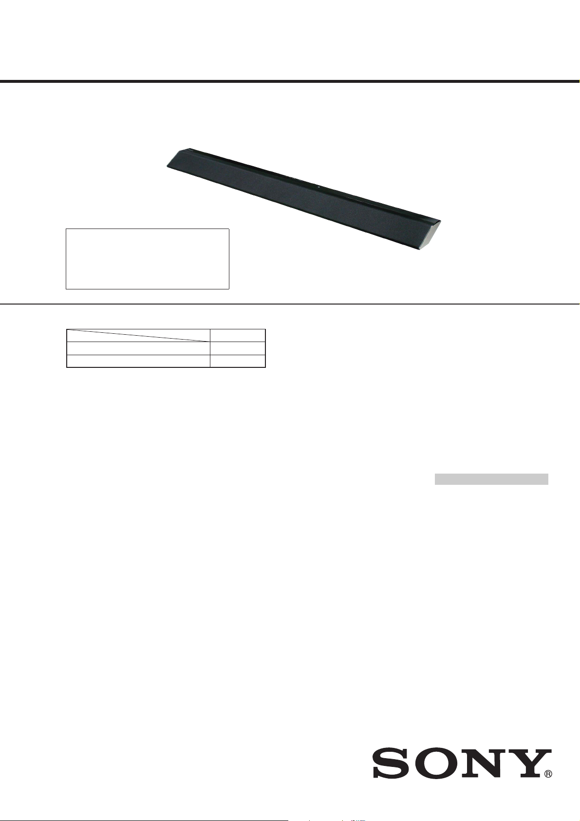
HT-CT780
T
SA-CT780
SERVICE MANUAL
Ver. 1.1 2015.04
• All of the units included in
the HT-CT780 (SA-CT780/
SA-WCT780/Remote control) are required to confi rm-
ing operation of SA-CT780.
Check in advance that you
have all of the units.
Note:
Be sure to keep your PC used for service and
checking of this unit always updated with the
latest version of your anti-virus software.
In case a virus affected unit was found during
service, contact your Service Headquarters.
COMPONENT MODEL NAME
HT-CT780
Bar Speaker (Active Speaker System) SA-CT780
Subwoofer (Active Subwoofer) SA-WCT780
• Please refer to service manual separately issued for Subwoofer.
Photo: SA-CT780
US Model
Canadian Model
AEP Model
UK Model
E Model
Australian Model
Chinese Model
PX Model
SPECIFICATIONS
Amplifier section
U.S. models:
POWER OUTPUT AND TOTA L HARMONIC
DISTORTION:
(FTC)
Front L + Front R:
With 4 ohms loads, both channels
driven, from 200 Hz - 20,000 Hz; rated
35 Watts per channel minimum RMS
power, with no more than 1% total
harmonic distortion from
250 milliwatts to rated output.
POWER OUTPUT (reference)
Front L/Front R: 105 Watts (per
channel at 4 ohms, 1 kHz)
Chinese model:
POWER OUTPUT (rated)
Front L + Front R:
35 W + 35 W (at 4 ohms, 1 kHz, 1%
THD)
Brazilian model:
he following values were measured at
127 V AC 60 Hz
RMS POWER OUTPUT:
Front L + Front R:
70 W (35 W per channel × 2, at 4
ohms, 1 kHz, 10% THD*)
* Total harmonic distortion
Other models:
POWER OUTPUT (rated)
Front L + Front R:
50 W + 50 W (a t 4 ohms, 1 kHz, 1%
THD)
POWER OUTPUT (reference)
Front L/Front R: 105 Watts (per
channel at 4 ohms, 1 kHz)
Inputs
HDMI IN* 1/2/3
ANALOG IN
DIGITAL IN (TV)
Outputs
HDMI OUT** (ARC)
* The 1 jack supports HDCP 2.2
protocol. HDCP 2.2 is newly enhanced
copyright protection technology that is
used to protect content such as 4K
movies. The 2 and 3 jacks are identical.
Using any of th
** The HDMI OUT jack support s
HDCP 2.2 protocol. HDCP 2.2 is newly
enhanced copyright protection
technology th at is used to protect
content such as 4K movies.
HDMI Section
Connector
Type A (19pin)
BLUETOOTH section
Communication system
BLUETOOTH Specification version 3.0
Output
BLUETOOTH Specification Power Class
2
Maximum communication range
Line of sight approx. 10 m (33 ft)
Maximum number of devices to be
registered
9 devices
Frequency band
2.4 GHz band (2.4000 GHz -
2.4835 GHz)
Modulation method
FHSS (Freq Hopp ing Spread Spectrum)
Compatible BLUETOOTH profiles
A2DP 1.2 (Advanced Audio Distribution
Profile)
AVRCP 1.3 (Audio Video Remote
Control Profile)
Supported Codecs
SBC4), AAC
Transmission range (A2DP)
20 Hz - 20,000 Hz (Sampling frequency
44.1 kHz)
em makes no difference.
2)
3)
5)
1)
The actual range will vary depending on
factors such as obstacles between
devices, magnetic fields around a
microwave oven, static electricity,
cordless phon e, reception sensitivity,
operating system, software application,
etc.
2)
BLUETOOTH sta ndard profiles indicate
the purpose of BLUETOOTH
communication between devices.
3)
Codec: Audio signal compression and
conversion format
4)
Subband Codec
5)
Advanced Audio Coding
Front L/Front R speaker section
Speaker system
2-way speaker system,
Acoustic suspension
Speaker
Woofer: 60 mm (2
cone type
1)
Tweeter: 19 mm (
soft dome type
General
Power requirements
120 V A C, 60 Hz (US, CND)
120 V AC, 50 Hz/60 Hz (TW)
110 V - 240 V AC, 50 Hz/60 Hz (PX, EA3, BR)
220 V - 240 V AC, 50 Hz/60 Hz (Other models)
Power consumption
On: 40 W
Standby: 0.3 W or less
(at the Power saving mode)
Standby: 0.5 W or less
(When [S. THRU] is [ON]: 6 W or less)
3
3
/4 in)
/8 in)
Dimensions (approx.) (w/h/d)
1,030 m m × 55 mm × 117 mm (40
1
/4in × 45/8in) (without wall
× 2
mounting brackets)
1,030 mm × 120 mm × 74 mm (40
3
/4in × 3 in) (with wall mounting
× 4
brackets)
Mass (approx.)
2.8 kg (6 lb 2
3
/4oz)
5
5
Wireless transmitter section
Speaker system
Wireless Sound Specification version
2.0
Frequency band
2.4 GHz (2.4000 GHz - 2.4835 GHz)
Modulation method
Pi / 4 DQPSK
Supplied accessories
Remote control (1)
R03 (size AAA) batteries (2)
Optical digital cable (1)
Wall mounting brackets (2) and screws (2)
Startup Guide (1)
Operating Instructions (1)
Design and specifications are subject to
change withou t notice.
HT-CT780
SOUND BAR
SA-CT780
/8in
/8in
9-896-146-02
2015D33-1
2015.04
©
ACTIVE SPEAKER SYSTEM
Sony Corporation
Published by Sony Techno Create Corporation
HT-CT780
Ver. 1.1
Copyrights and Trademarks
This system in corporates Dolby* Digital
and the DTS** Digital Surround System.
* Manufactured under license from
Dolby Laboratories.
Dolby, and the double-D symbo l are
trademarks of Dolby Laboratories.
** For DTS patents, see http://
patents.dts.com. Manufactured
under license from DTS Licensing
Limited. DTS, DTS-HD, the Symbol, &
DTS and the Symbol together are
registered trademarks of DT S, Inc.
© DTS, Inc. All Rights Reserved.
®
The BLUETOOTH
are registered trademarks owned by
Bluetooth SIG, Inc. and any use of such
marks by Sony Corporation is under
license.
This system incorporates HighDefinition Multimedia Interface
(HDMI™) technology.
The terms HDMI and HDMI HighDefinition Multimedia Interface, a nd the
HDMI Logo are trademarks or registered
trademarks of HDMI Licensing LLC in the
United States and other coun tries.
The N Mark is a trademark or registered
trademark of NFC Forum, Inc. in the
United States and in other countries.
Android™ and Google Play™ are
trademarks of Google Inc.
Apple, the Apple logo, iPhon e, iPod, and
iPod touch are trademarks of Appl e Inc.,
registered in the U.S. and oth er
countries. App Store is a service mark of
Apple Inc.
word mark and logos
SAFETY CHECK-OUT
After correcting the original service problem, perform the following safety check before releasing the set to the customer:
Check the antenna terminals, metal trim, “metallized” knobs,
screws, and all other exposed metal parts for AC leakage.
Check leakage as described below.
LEAKAGE TEST
The AC leakage from any exposed metal part to earth ground and
from all exposed metal parts to any exposed metal part having a
return to chassis, must not exceed 0.5 mA (500 microamperes.).
Leakage current can be measured by any one of three methods.
1. A commercial leakage tester, such as the Simpson 229 or RCA
WT-540A. Follow the manufacturers’ instructions to use these
instruments.
2. A battery-operated AC milliammeter. The Data Precision 245
digital multimeter is suitable for this job.
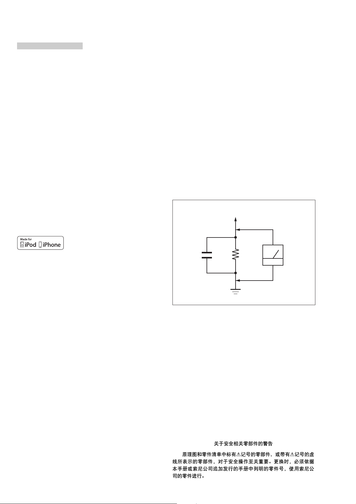
3. Measuring the voltage drop across a resistor by means of a
VOM or battery-operated AC voltmeter. The “limit” indication
is 0.75 V, so analog meters must have an accurate low-voltage
scale. The Simpson 250 and Sanwa SH-63Trd are examples
of a passive VOM that is suitable. Nearly all battery operated
digital multimeters that have a 2 V AC range are suitable. (See
Fig. A)
To Exposed Metal
Parts on Set
“Made for iPod,” and “Made for iPhone ”
mean that an electronic accessory has
been designed to connect spec ifically to
iPod or iPhone, respectively, and has
been certified by the developer to meet
Apple performance standards. Apple is
not responsible for the operation of this
device or its compliance with safety and
regulatory standards. Please note that
the use of this accessory with iPod or
iPhone may affect wireless
performance.
Compatible iPod/iPhone models
The compatible iPod/iPhone models
are as follows. Update your iPod/iPhone
with the latest software before using
with the system.
BLUETOOTH technology works with:
iPhone 6 Plus/iPhone 6/iPhone 5s/
iPhone 5c/iPhone 5/iPhone 4s/
iPhone 4/iPhone 3GS
iPod touch (5th gene ration)/iPod touch
(4th generation)
“BRAVIA” logo is a trademark of Sony
Corporation.
“DSEE” is a trademark of Sony
Corporation.
“ClearAudio+” is a trademark of Sony
Corporation.
“x.v.Color” and “x.v.Col or” logo are
trademarks of Sony Corporation.
“PlayStation
of Sony Computer Entertainment Inc.
Other trademarks and trade names are
those of their respective owners.
” is a registered trademark
®
AC
1.5 kΩ0.15 μF
voltmeter
(0.75 V)
Earth Ground
Fig. A. Using an AC voltmeter to check AC leakage.
SAFETY-RELATED COMPONENT WARNING!
COMPONENTS IDENTIFIED BY MARK 0 OR DOTTED LINE
WITH MARK 0 ON THE SCHEMATIC DIAGRAMS AND IN
THE PARTS LIST ARE CRITICAL TO SAFE OPERATION.
REPLACE THESE COMPONENTS WITH SONY PARTS
WHOSE PART NUMBERS APPEAR AS SHOWN IN THIS
MANUAL OR IN SUPPLEMENTS PUBLISHED BY SONY.
ATTENTION AU COMPOSANT AYANT RAPPORT
LES COMPOSANTS IDENTIFIÉS PAR UNE MARQUE 0 SUR
LES DIAGRAMMES SCHÉMATIQUES ET LA LISTE DES
PIÈCES SONT CRITIQUES POUR LA SÉCURITÉ DE FONCTIONNEMENT. NE REMPLACER CES COMPOSANTS QUE
PAR DES PIÈCES SONY DONT LES NUMÉROS SONT DONNÉS DANS CE MANUEL OU DANS LES SUPPLÉMENTS
PUBLIÉS PAR SONY.
À LA SÉCURITÉ!
NOTES ON CHIP COMPONENT REPLACEMENT
• Never reuse a disconnected chip component.
• Notice that the minus side of a tantalum capacitor may be damaged by heat.
2

TABLE OF CONTENTS
HT-CT780
1. SERVICING NOTES ............................................. 4
2. DISASSEMBLY
2-1. Disassembly Flow ........................................................... 7
2-2. Top Panel Block .............................................................. 8
2-3. How to Install the Connection Cable with Speaker
(L-ch, R-ch) (SPC1, SPC2) ............................................. 9
2-4. Speaker (60 mm) (L-ch, R-ch) (SP1, SP2),
Speaker (19 mm) (L-ch, R-ch) (SP3, SP4) ..................... 10
2-5. NFC Module (NFC1) ...................................................... 11
2-6. FL Board ......................................................................... 12
2-7. POWER Board ................................................................ 13
2-8. RF Modulator (RF1) ....................................................... 14
2-9. Connection Cable with Speaker (L-ch, R-ch)
(SPC1, SPC2) .................................................................. 15
2-10. KEY Board, Key ............................................................. 16
2-11. MAIN Board ................................................................... 17
2-12. Power Cord (AC1) .......................................................... 18
2-13. Bluetooth Module (BT1) ................................................ 19
2-14. Bottom Chassis Block ..................................................... 20
2-15. Service Position .............................................................. 21
3. TEST MODE ............................................................ 22
4. TROUBLESHOOTING .......................................... 27
5. DIAGRAMS
5-1. Block Diagram - HDMI Section - ................................... 31
5-2. Block Diagram - MAIN Section - ................................... 32
5-3. Block Diagram - AMP Section - ..................................... 33
5-4. Block Diagram
- PANEL/POWER SUPPLY Section - ............................ 34
5-5. Printed Wiring Boards - MAIN Section (1/2) - .............. 36
5-6. Printed Wiring Board - MAIN Section (2/2) - ................ 37
5-7. Schematic Diagram - MAIN Section (1/8) - ................... 38
5-8. Schematic Diagram - MAIN Section (2/8) - ................... 39
5-9. Schematic Diagram - MAIN Section (3/8) - ................... 40
5-10. Schematic Diagram - MAIN Section (4/8) - ................... 41
5-11. Schematic Diagram - MAIN Section (5/8) - ................... 42
5-12. Schematic Diagram - MAIN Section (6/8) - ................... 43
5-13. Schematic Diagram - MAIN Section (7/8) - ................... 44
5-14. Schematic Diagram - MAIN Section (8/8) - ................... 45
5-15. Printed Wiring Board - FL Board - ................................. 46
5-16. Schematic Diagram - FL Board - .................................... 47
5-17. Printed Wiring Board - POWER Board - ........................ 48
5-18. Schematic Diagram - POWER Board - .......................... 49
6. EXPLODED VIEWS
6-1. Overall Section ............................................................... 62
6-2. Top Panel Section ........................................................... 63
6-3. Bottom Panel Section ...................................................... 64
6-4. MAIN Board Section ...................................................... 65
7. ELECTRICAL PARTS LIST .............................. 66
Accessories are given in the last of the electrical parts list.
3
HT-CT780
Ver. 1.1
SECTION 1
SERVICING NOTES
The SERVICING NOTES contains important information for servicing. Be sure to read this section before repairing the unit.
UNLEADED SOLDER
Boards requiring use of unleaded solder are printed with the leadfree mark (LF) indicating the solder contains no lead.
(Caution: Some printed circuit boards may not come printed with
the lead free mark due to their particular size)
: LEAD FREE MARK
Unleaded solder has the following characteristics.
• Unleaded solder melts at a temperature about 40 °C higher
than ordinary solder.
Ordinary soldering irons can be used but the iron tip has to be
applied to the solder joint for a slightly longer time.
Soldering irons using a temperature regulator should be set to
about 350 °C.
Caution: The printed pattern (copper foil) may peel away if
the heated tip is applied for too long, so be careful!
• Strong viscosity
Unleaded solder is more viscous (sticky, less prone to fl ow)
than ordinary solder so use caution not to let solder bridges
occur such as on IC pins, etc.
• Usable with ordinary solder
It is best to use only unleaded solder but unleaded solder may
also be added to ordinary solder.
NOTE OF PERFORMING THE OPERATION CHECK IN
THE STATE THAT HEAT SINK WAS REMOVED
When performing the operation check in the state that this unit was
disassembled, it is possible to perform the operation check in the
state that heat sink was removed. But don’t perform the operation
check in the long time, and perform the operation check in the
volume state as low as possible.
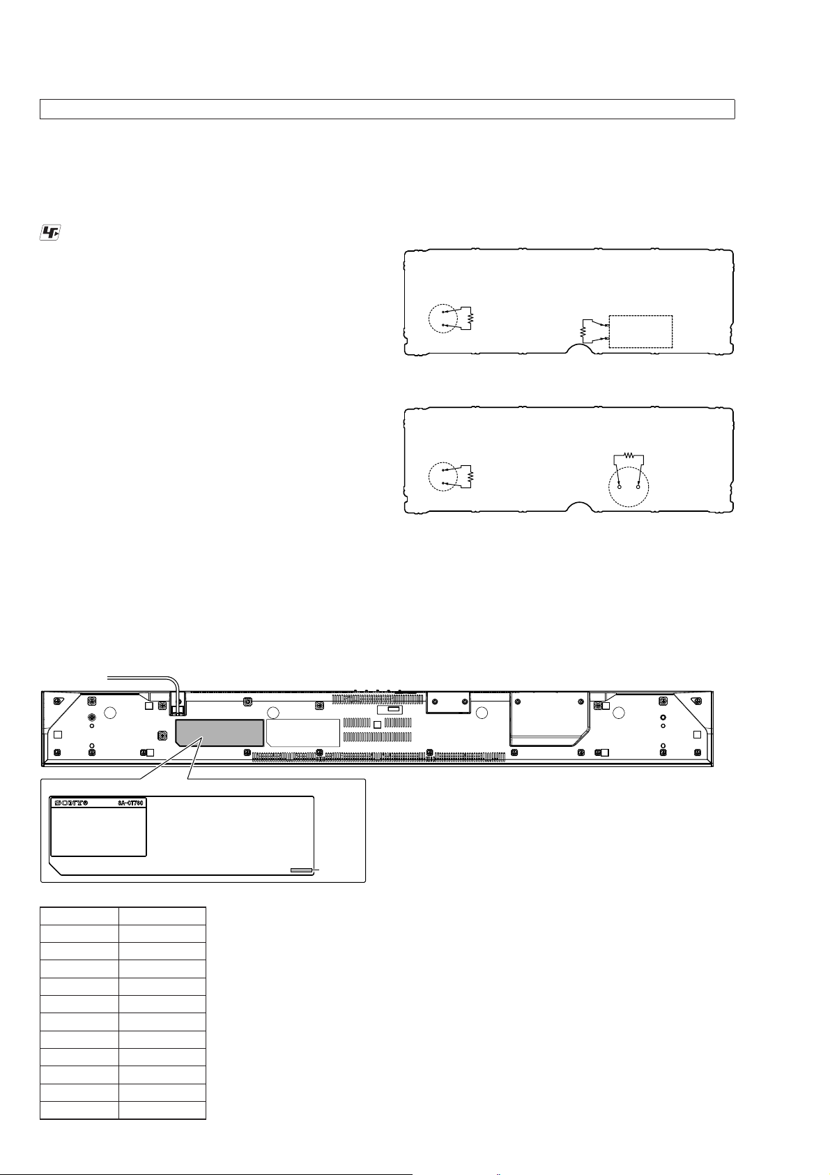
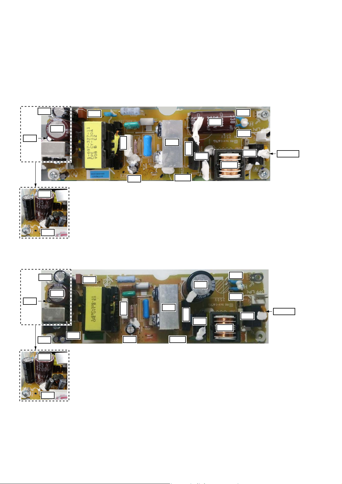
CAPACITOR ELECTRICAL DISCHARGE PROCESSING
When checking the board, for the electric shock prevention, connect the resistors to both ends of respective capacitors to discharge
the capacitor.
– POWER Board (Conductor Side) –
(US, Canadian and Taiwan models)
C967
800 :/2 W
800 :/2 W
C914
– POWER Board (Conductor Side) –
(Except US, Canadian and Taiwan models)
C967
800 :/2 W
800 :/2 W
C915
MODEL IDENTIFICATION
Distinguish by Part No. on the bottom side of the main unit.
MODEL NUMBER LABEL
Part No.
Destination Part No.
US, CND
AEP
UK
EA3
PX
SP
CH
AUS
TW
BR
E3
4-564-208-0[]
4-564-209-0[]
4-564-209-1[]
4-564-211-0[]
4-567-467-0[]
4-567-468-0[]
4-567-469-0[]
4-567-470-0[]
4-567-471-0[]
4-569-640-0[]
4-570-359-0[]
– Bottom view –
4
HT-CT780
j
j
Ver. 1.1
DESTINATION ABBREVIATIONS
The following abbreviations for model destinations are used in this
service manual.
• Abbreviations
AUS : Australian model
BR : Brazilian model
CH : Chinese model
CND : Canadian model
E3 : African and Iranian models
EA3 : Saudi Arabia, UAE, Kuwait, Iraqi, Kenyan, Tanzanian and
Nigerian models
SP : Singapore model
TW : Taiwan model
ADVANCE PREPARATION WHEN CONFIRMING OPERATION
All of the units included in the HT-CT780 (SA-CT780/SAWCT780/Remote control) are required to confi rming operation of
SA-CT780. Check in advance that you have all of the units.
NOTE OF REPLACING THE KEY BOARD
When the KEY board is defective, replace the complete mounted
board.
NOTE OF REPLACING THE IC102, IC104, IC307, IC308,
IC313, IC601 TO IC603, IC605, IC1002, IC1004 AND
IC1501 ON THE MAIN BOARD
IC102, IC104, IC307, IC308, IC313, IC601 to IC603, IC605,
IC1002, IC1004 and IC1501 on the MAIN board cannot replace
with single. When these parts are damaged, replace the complete
mounted board.
NOTE OF REPLACING THE IC503 ON THE MAIN
BOARD AND THE COMPLETE MAIN BOARD
When IC503 on the MAIN board and the complete MAIN board
are replaced, it is necessary to spread the compound between the
MAIN board and the heat sink.
Spread the compound referring to the fi gure below.
– MAIN Board (Side A) –
compound
IC503
NOTES ON THE WIRELESS CONNECTION (LINK) AFTER
REPAIRS ARE COMPLETE
When the parts below is replaced, the wireless connection (LINK)
of the Bar speaker and Subwoofer will be disconnected.
Before returning repaired products to the customer, follow the procedure below to LINK the Bar speaker and Subwoofer.
Also, if only the Bar speaker or Subwoofer is brought in for repair
and the parts below are replaced, be sure to inform the customer
when returning the repaired products that the customer must LINK
the Bar speaker and Subwoofer.
(Indicate that the LINK procedure is described in the operating
instructions)
Parts in which the LINK will be disconnected due to replacement:
• Complete MAIN board
• RF modulator (SWA12-4V TX) (Ref. No. RF1)
Linking the system (Link to the Subwoofer)
Set up the wireless subwoofer
connection again.
1 Press MENU.
2 Select [WS] with
press ENTER.
3 Select [LINK] with
press ENTER.
(select), then
(select), then
4 When [START] appears on the
display, press ENTER.
[SEARCH] appears, and the Bar
Speaker searches for a device that
can be used with Link. Proceed to
the next step within 1 minute.
To quit the Link function while
searching for a device, press BACK.
5 Press LINK on the subwoofer.
The on/standby indicator on the
subwoofer lights up in green. [OK]
appears on the display of the Bar
Speaker.
If [FAILED] appears, check to ensure
the subwoofer is turned on and
perform the process again from
step 1.
6 Press MENU.
The menu turns off.
IF “PRTECT (PROTECT)” APPEARS ON THE FRONT
PANEL DISPLAY OF THE BAR SPEAKER
Press the Ò/Æ (on/standby) button
on the Bar Speaker to turn off the
system. After the display stops
flashing, disconnect the AC power
cord (mains lead) then check that
nothing is blocking the ventilation
holes of the Bar Speaker.
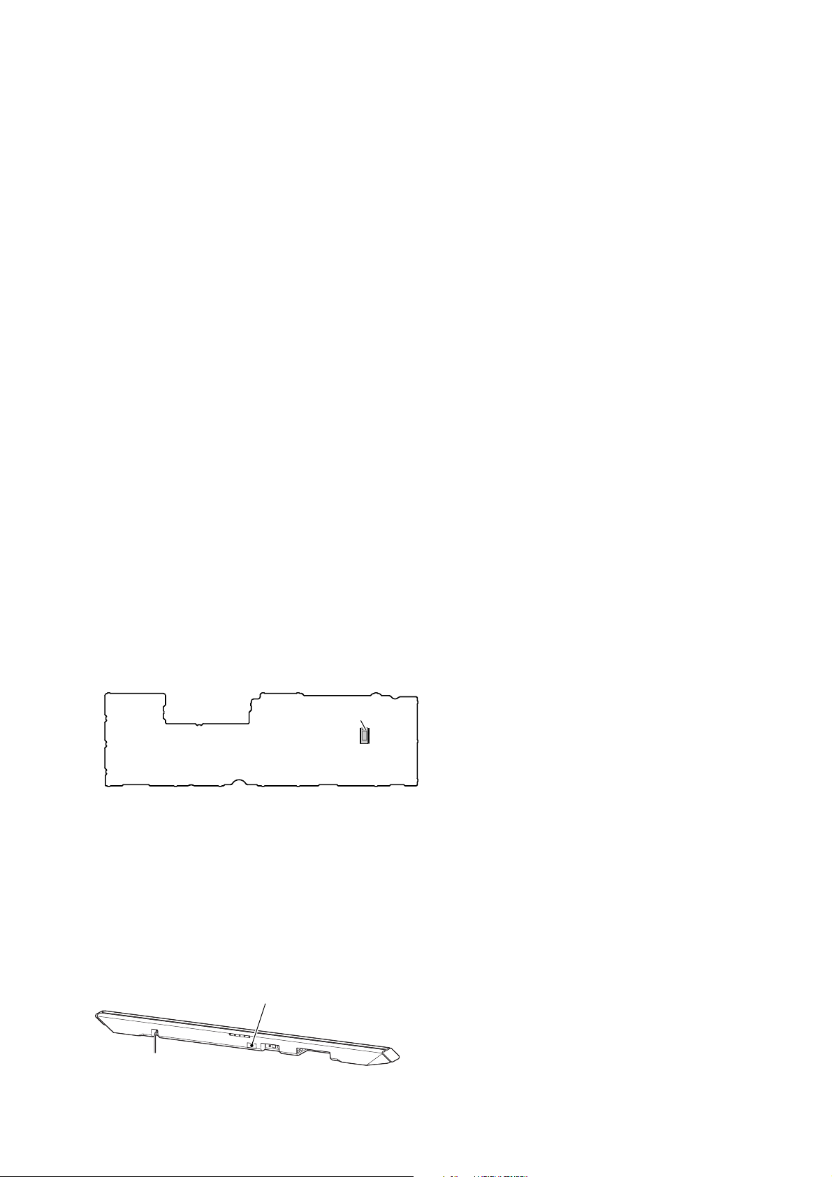
NOTES ON UPDATE PORT
UPDATE port
This is update dedicated port of this unit.
Use this port only when updating this unit.
– Rear view –
5
HT-CT780
Ver. 1.1
BOND FIXATION OF ELECTRIC PARTS
When complete POWER board or the following parts are replaced, it is necessary to fi x the parts by using the bond (SC608Z2) (Refer to
the fi gure below).
• POWER board:
C902, C903, C905, C914 or C915, C941, C967, C970, C977, C978, C980, C988, D901, F931, LF901, R934, TH901, VDR901
(C978, C980: Except US, Canadian and Taiwan models only)
– POWER Board (Component Side) –
(US, Canadian and Taiwan models)
C977
C970
C967
F931
R934
A932
D901
C988
C914
LF901
C902
C903
C905
VDR901
C967
C977
– Side view –
– POWER Board (Component Side) –
(Except US, Canadian and Taiwan models)
C970
C967
C977
C980
F931
C978
C941
R934
C941
A932
TH901
TH901
D901
C915
C988
LF901
C902
C903
C905
VDR901
6
C967
C977
– Side view –
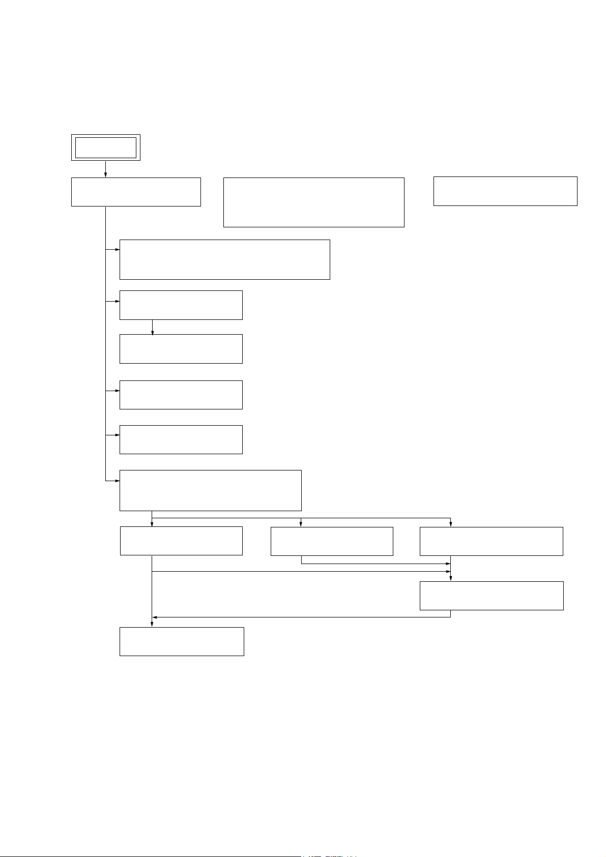
DISASSEMBLY
• This set can be disassembled in the order shown below.
2-1. DISASSEMBLY FLOW
SET
HT-CT780
SECTION 2
2-2. TOP PANEL BLOCK
(Page 8)
2-4. SPEAKER (60 mm) (L-CH, R-CH) (SP1, SP2),
SPEAKER (19 mm) (L-CH, R-CH) (SP3, SP4)
(Page 10)
2-5. NFC MODULE (NFC1)
(Page 11)
2-6. FL BOARD
(Page 12)
2-7. POWER BOARD
(Page 13)
2-8. RF MODULATOR (RF1)
(Page 14)
2-9. CONNECTION CABLE WITH SPEAKER
(L-CH, R-CH) (SPC1, SPC2)
(Page 15)
2-3. HOW TO INSTALL THE CONNECTION
CABLE WITH SPEAKER (L-CH, R-CH)
(SPC1, SPC2)
(Page 9)
2-15. SERVICE POSITION
(Page 21)
2-10. KEY BOARD, KEY
(Page 16)
2-11. MAIN BOARD
(Page 17)
2-12. POWER CORD (AC1)
(Page 18)
2-13. BLUETOOTH MODULE (BT1)
(Page 19)
2-14. BOTTOM CHASSIS BLOCK
(Page 20)
7
HT-CT780
Note: Follow the disassembly procedure in the numerical order given.
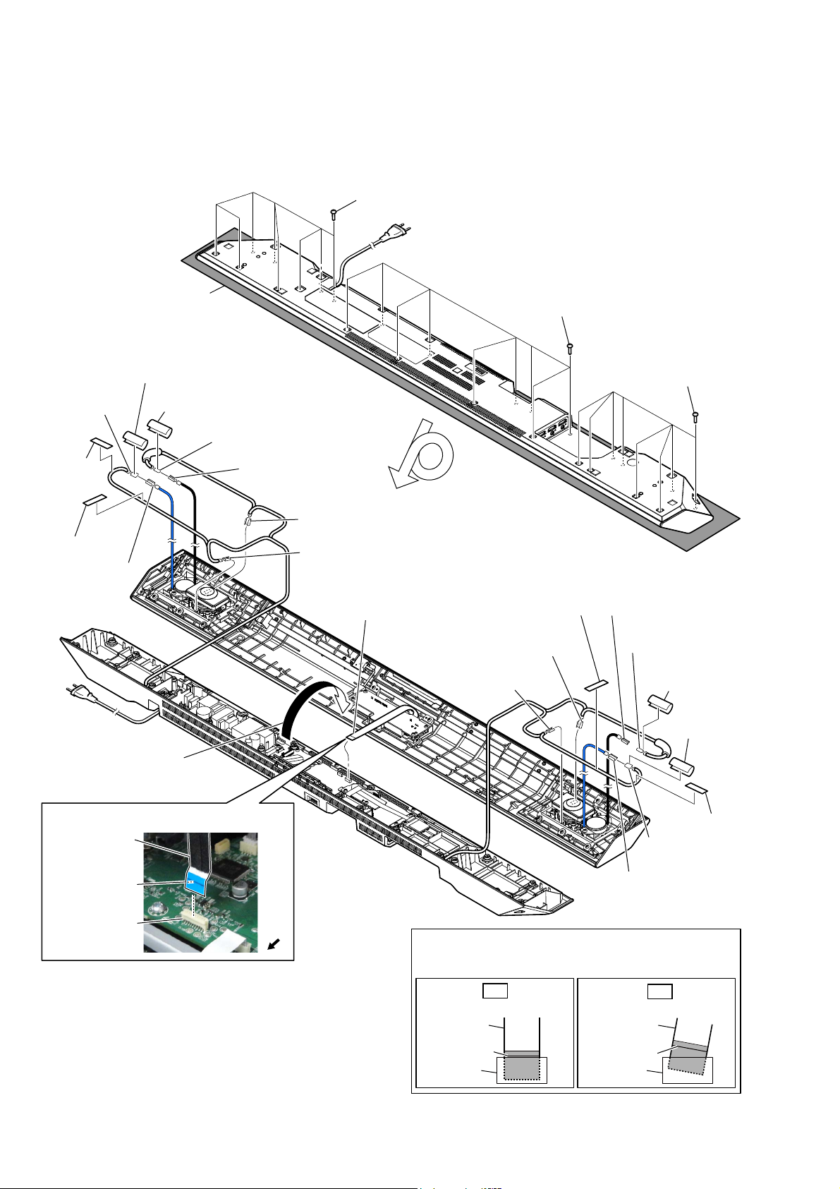
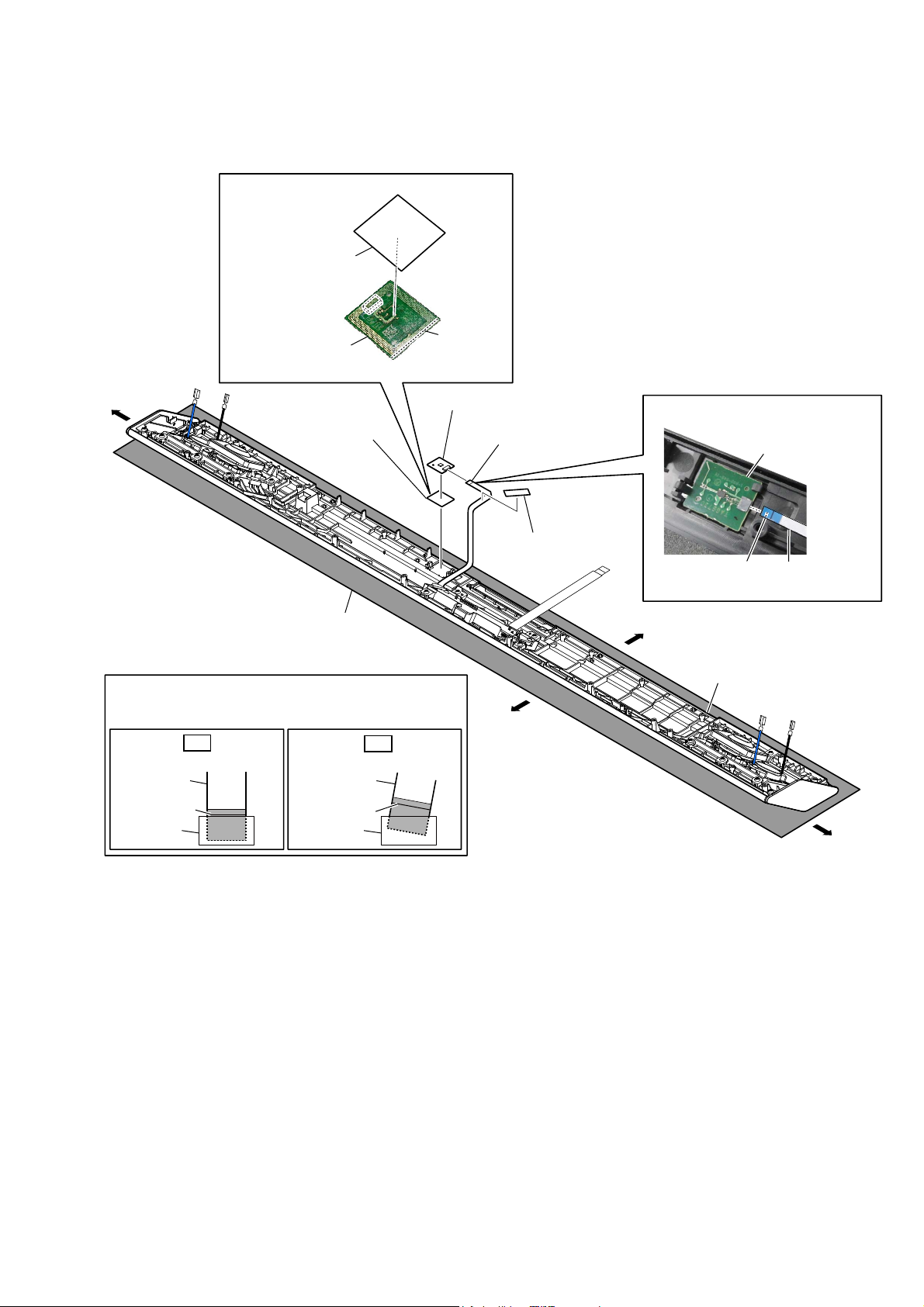
2-2. TOP PANEL BLOCK
• For the speaker cable setting, see page 9.
Please spread a sheet under a
Note:
unit not to injure top panel.
1 eight screws
(BVTP3 u 10)
1 nine screws
(BVTP3 u 10)
6 terminal
[black]
(wide side)
4 cushion
(CZ)
4 cushion (CZ)
6 terminal [blue]
(wide side)
2 Remove the top panel
block in the direction
of the arrow.
5 cushion top
5 cushion top
6 terminal [red]
(narrow side)
6 terminal [black]
(narrow side)
7 terminal [red]
(wide side)
7 terminal [black]
(narrow side)
3 flexible flat cable
(18 core) (FFC3)
(CN104)
7 terminal [black]
(narrow side)
4 cushion (CZ)
7 terminal [gray]
(wide side)
1 eight screws
(BVTP3 u 10)
– Bottom view –
6 terminal [black]
(narrow side)
6 terminal [gray]
(narrow side)
5 cushion top
5 cushion top
)OH[LEOHIODWFDEOH))&VHWWLQJ
flexible flat cable
(18 core) (FFC3)
Terminal face is
below side.
connector
(CN104)
8
front
side
4 cushion (CZ)
6 terminal [black]
(wide side)
6 terminal [blue]
(wide side)
– Rear view –
How to install the flexible flat cable
When installing the flexible flat cable, ensure that
the colored line is parallel to the connector after insertion.
OK
Insert straight into the interior.
flexible flat
cable
colored line
connector
flexible flat
cable
colored line
connector
NG
Insert at a slant.
HT-CT780
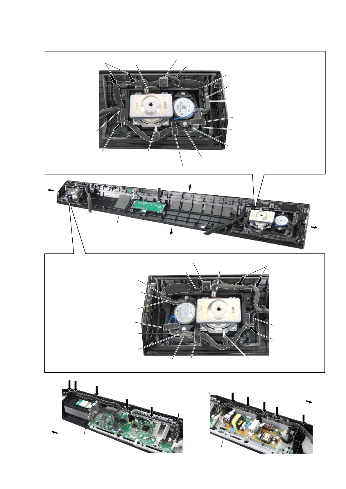
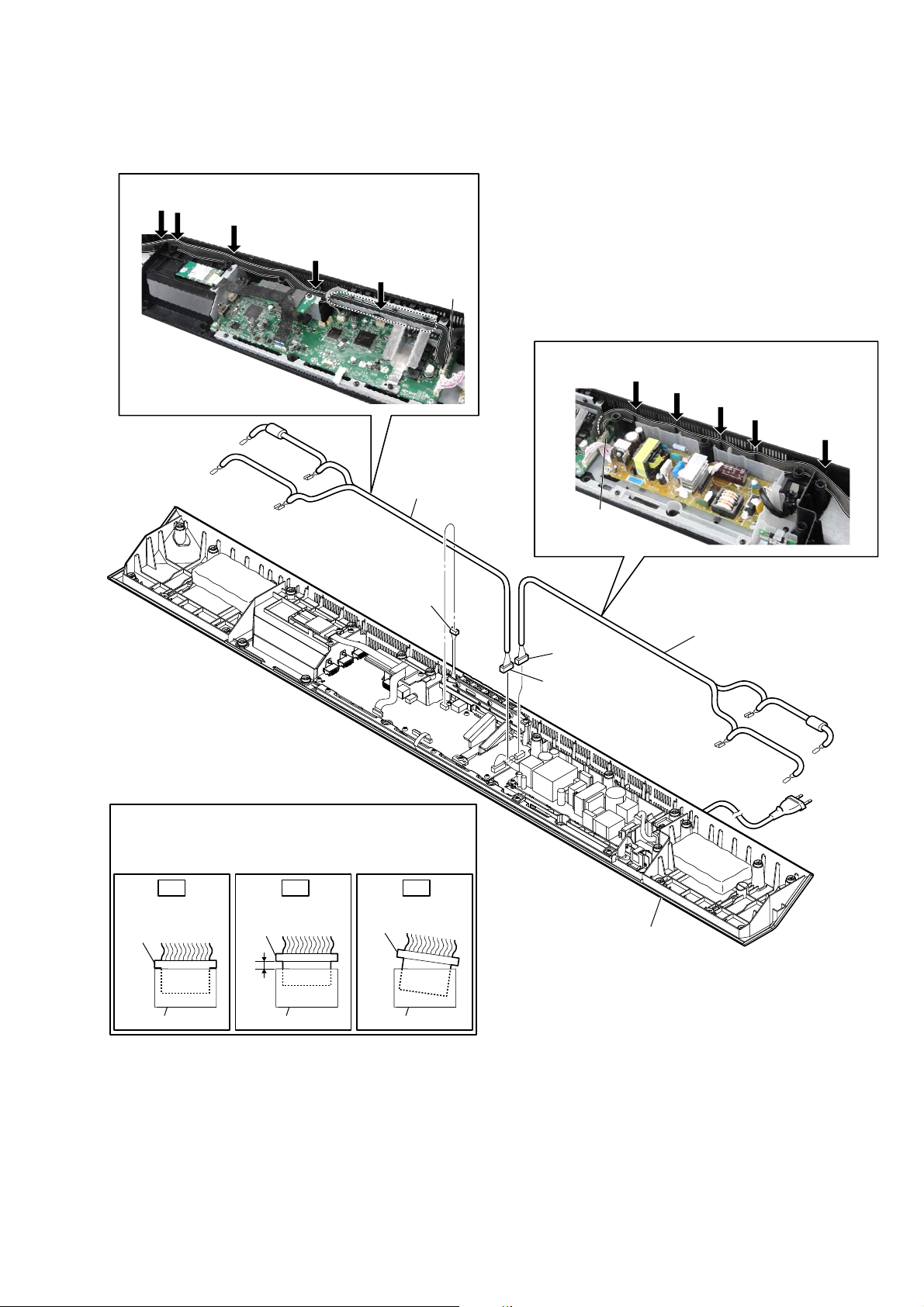
2-3. HOW TO INSTALL THE CONNECTION CABLE WITH SPEAKER (L-CH, R-CH) (SPC1, SPC2)
2 Push the cable
into the slots.
qd Pass the cable
underneath catcher.
qs Push the cable
into the slot.
right side
1 Connect the terminal
[gray] (wide side).
5 Connect the terminal
[black] (narrow side).
top block
3 Pass the cable underneath catcher.
4 Pass the cable along the rib.
0 Pass the cable underneath catcher.
8 Connect the terminals
[gray] and [black] (narrow side).
9 Wrap up wire from speaker (19 mm) and
connection cable with speaker (SPC1).
qf Paste the cushion (CZ).
7 Wrap up wire from speaker (19 mm) and
connection cable with speaker (SPC1).
6 Connect the terminals
[black] and [blue] (wide side).
qa Pass the cable along the speaker (19 mm).
qf Paste the cushion (CZ).
rear side
left side
3 Pass the cable underneath catcher.
4 Pass the cable along the rib.
0 Pass the cable underneath catcher.
9 Wrap up wire from speaker (19 mm) and
connection cable with speaker (SPC2).
8 Connect the terminals
[gray] and [black] (narrow side).
qf Paste the cushion (CZ).
7 Wrap up wire from speaker (19 mm) and
connection cable with speaker (SPC2).
6 Connect the terminals
[black] and [blue] (wide side).
qa Pass the cable along the speaker (19 mm).
Push
Push
Push
Push
Push
front side
CN502
1 Connect the terminal
[red] (wide side).
qf Paste the cushion (CZ).
CN501
Push
2 Push the cable
into the slots.
qd Pass the cable
underneath catcher.
qs Push the cable
into the slot.
5 Connect the terminal
[black] (narrow side).
Push
Push
Push
right side
Push
left side
bottom block
bottom block
9

HT-CT780
2-4. SPEAKER (60 mm) (L-CH, R-CH) (SP1, SP2), SPEAKER (19 mm) (L-CH, R-CH) (SP3, SP4)
6SHDNHUPP5FK63DQG
VSHDNHUPP5FK63setting
[black]
wide terminal side
red line
right side
[blue]
front side
speaker (19 mm)
(R-ch) (SP4)
right side
speaker (60 mm)
(R-ch) (SP2)
3 two screws
(3.5)
narrow terminal side
4 speaker (19 mm)
(R-ch) (SP4)
2 speaker (60 mm)
(R-ch) (SP2)
left side
1 four screws
(3.5)
top block
6SHDNHUPP/FK63DQG
VSHDNHUPP/FK63setting
speaker (60 mm)
(L-ch) (SP1)
right side
narrow terminal side
2 speaker (60 mm)
(L-ch) (SP1)
wide terminal side
[blue]
1 four screws
(3.5)
rear side
red line
3 two screws
(3.5)
speaker (19 mm)
(L-ch) (SP3)
left side
[black]
front side
10
Please spread a sheet under a
Note:
unit not to injure top panel.
front side
– Top panel block bottom view –
4 speaker (19 mm)
(L-ch) (SP3)
left side
2-5. NFC MODULE (NFC1)
+RZWRLQVWDOOWKHGRXEOHDGKHVLYHWDSH1)&
double adhesive
tape (NFC)
HT-CT780
NFC module (NFC1)
– NFC module bottom view –
right side
3 Peel off the double
adhesive tape (NFC).
Please spread a sheet under a
Note:
unit not to injure top panel.
+RZWRLQVWDOOWKHIOH[LEOHIODWFDEOH
When installing the flexible flat cable, ensure that
the colored line is parallel to the connector after insertion.
OK
Insert straight into the interior.
flexible flat
cable
colored line
connector
flexible flat
cable
colored line
connector
NG
Insert at a slant.
guide line
4 NFC module
(NFC1)
2 flexible flat cable
(6 core) (FFC4)
front side
)OH[LEOHIODWFDEOH))&VHWWLQJ
1 cushion (QV, A)
Terminal face is
below side.
rear side
top block
– Top panel block bottom view –
NFC module
(NFC1)
flexible flat cable
(6 core) (FFC4)
left side
11
HT-CT780
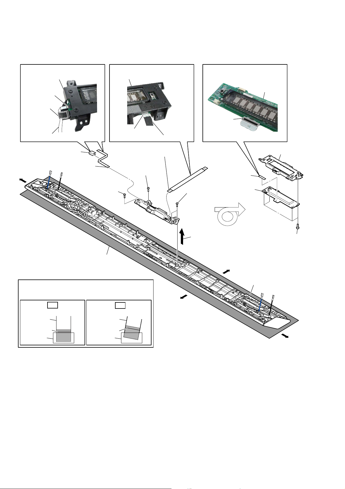
2-6. FL BOARD
)OH[LEOHIODWFDEOH))&VHWWLQJ )OH[LEOHIODWFDEOH))&VHWWLQJ +RZWRLQVWDOOWKHFXVKLRQ&=
FL board block
FL board block
terminal side
cushion (QV, A)
flexible flat cable (6 core) (FFC4)
4 cushion (QV, A)
5 flexible flat cable
(6 core) (FFC4) (CN804)
right side
Please spread a sheet under a
Note:
unit not to injure top panel.
1 screw
(BVTP3 u 10)
terminal side
flexible flat cable (18 core) (FFC3)
3 flexible flat cable
(18 core) (FFC3) (CN803)
1 screw
(BVTP3 u 10)
cushion (CZ)
8 cushion (CZ)
1 two screws
(BVTP3 u 10)
2 Remove the FL board block
in the direction of the arrow.
9 FL board
rear side
FL board
7 holder FL
6 four screws
(BVTP3 u 10)
+RZWRLQVWDOOWKHIOH[LEOHIODWFDEOH
When installing the flexible flat cable, ensure that
the colored line is parallel to the connector after insertion.
OK
Insert straight into the interior.
flexible flat
cable
colored line
connector
flexible flat
cable
colored line
connector
NG
Insert at a slant.
front side
–7RSSDQHOEORFNERWWRPYLHZ–
top block
left side
12
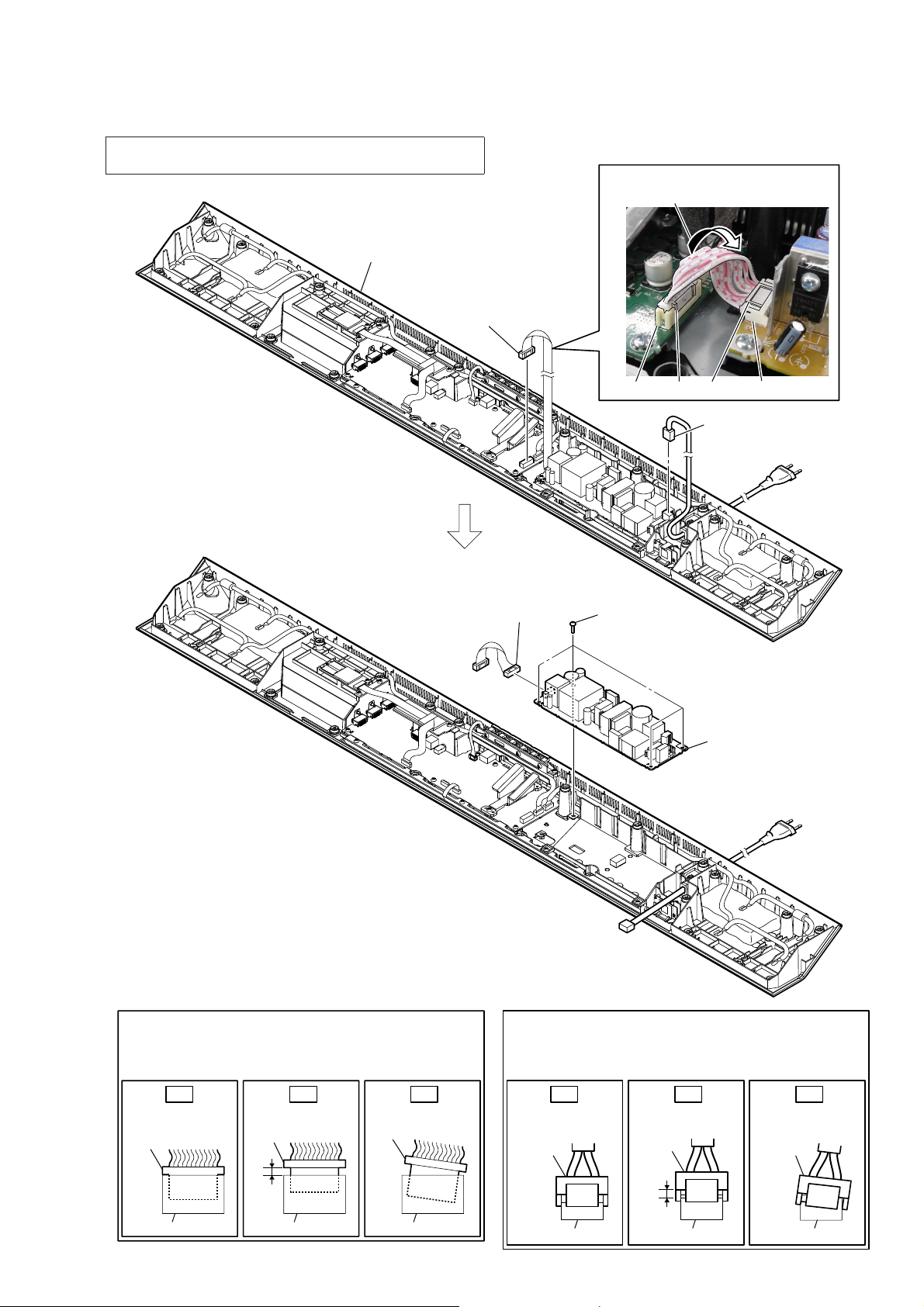
2-7. POWER BOARD
Note: When the complete POWER board is replaced, refer to “BOND
FIXATION OF ELECTRIC PARTS” on page 6.
bottom block
1 connector
(CN601)
HT-CT780
Wire setting
Twist the wire.
4 connector
(CN902)
CN601
3 four screws
(BV3)
boss
CN902boss
2 power cord connector
(CN901)
5 POWER board
How to install the connector
Insert the connector straight into the interior.
There is a possibility that using this unit without
the connector correctly installed will damage it.
OK NG NG
the interior.
connector
connector
Insert only part way.Insert straight into
connector
connector connector
Insert at a slant.
connector
How to install the power cord connector
Insert the connector straight into the interior.
There is a possibility that using this unit without
the connector correctly installed will damage it.
OK NG NG
the interior.
connector
connector
Insert only part way.Insert straight into
connector
connector connector
Insert at a slant.
connector
13
HT-CT780
2-8. RF MODULATOR (RF1)
Note: When the RF modulator (Ref. No. RF1) is replaced, refer to
“NOTES ON THE WIRELESS CONNECTION (LINK) AFTER
REPAIRS ARE COMPLETE” on page 5.
+RZWRLQVWDOOWKHFKVKLRQ49$
cushion (QV, A)
RF modulator
(RF1)
7 RF modulator
(RF1)
6 cushion (QV, A)
3 screw
(P3 u 8)
5 flexible flat cable
(24 core) (FFC2)
2 cushion (CZ)
)OH[LEOHIODWFDEOH))&VHWWLQJ
RF modulator
(RF1)
terminal face
flexible flat cable
(FFC2)
cushion (CZ)
claw
4 Remove the RF modulator block
in the direction of the arrow.
1 connector
(CN103)
+RZWRLQVWDOOWKHIOH[LEOHIODWFDEOH
When installing the flexible flat cable, ensure that
the colored line is parallel to the connector after insertion.
OK
Insert straight into the interior.
flexible flat
cable
colored line
connector
flexible flat
cable
colored line
connector
NG
Insert at a slant.
Terminal face is
below side.
connector
(CN103)
bottom block
14
2-9. CONNECTION CABLE WITH SPEAKER (L-CH, R-CH) (SPC1, SPC2)
&RQQHFWLRQFDEOHZLWKVSHDNHU/FK63&VHWWLQJ
Push
Push
Push
Push
Push
CN502
&RQQHFWLRQFDEOHZLWKVSHDNHU5FK63&VHWWLQJ
HT-CT780
1 connector
(CN105)
+RZWRLQVWDOOWKHFRQQHFWRU
Insert the connector straight into the interior.
There is a possibility that using this unit without
the connector correctly installed will damage it.
3 connection cable
with speaker
(L-ch) (SPC1)
CN501
2 connector
(CN501)
2 connector
(CN502)
Push
Push
Push
Push
3 connection cable with speaker
(R-ch) (SPC2)
Push
OK NG NG
the interior.
connector
connector
Insert only part way.Insert straight into
connector
connector connector
Insert at a slant.
connector
bottom block
15
HT-CT780
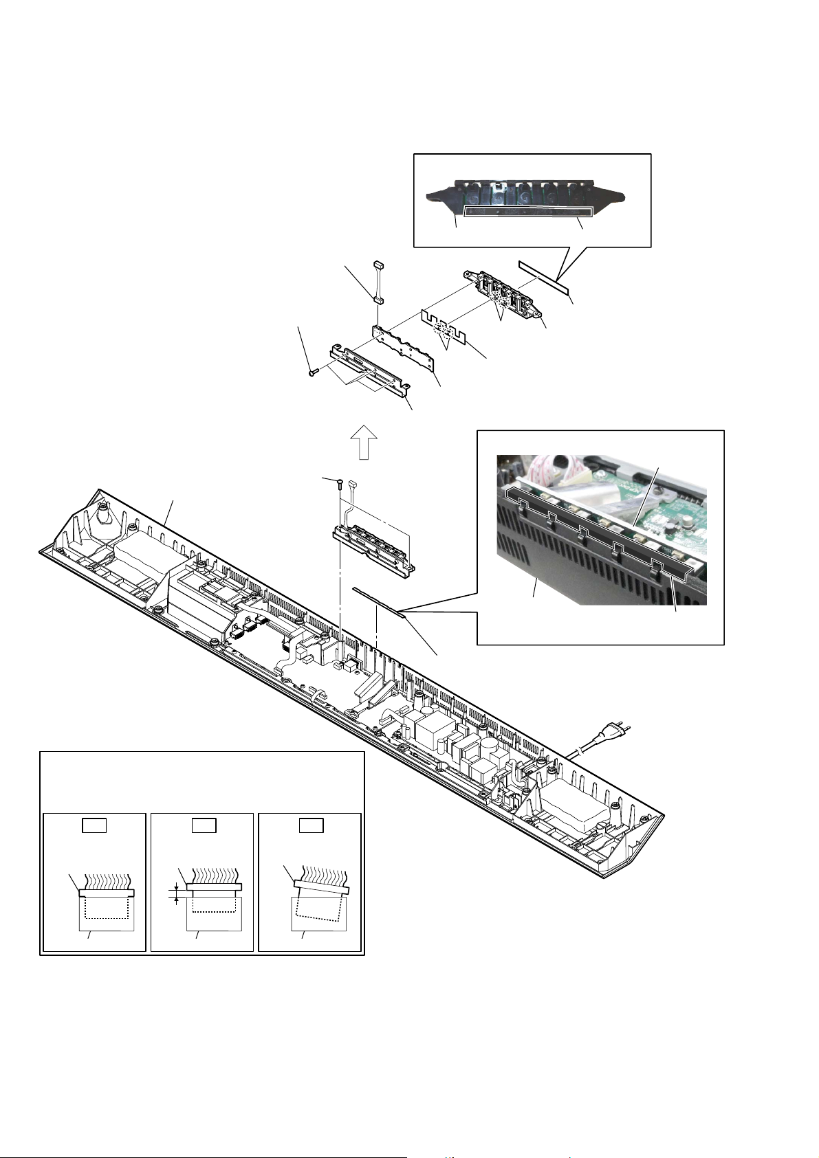
2-10. KEY BOARD, KEY
,QVWDOODWLRQSRVLWLRQRIWKHFXVKLRQ&=
bottom block
3 connector
(CN871)
4 four screws
(BVTP3 u 10)
2 two screws
(BVTP3 u 10)
key
hole
9 KEY board
5 bracket key
cushion (CZ)
6 cushion (CZ)
boss
7 cushion key
,QVWDOODWLRQSRVLWLRQRIWKHFXVKLRQNH\WRS
bottom block
8 key
KEY board
cushion key top
–5HDUYLHZ–
+RZWRLQVWDOOWKHFRQQHFWRU
Insert the connector straight into the interior.
There is a possibility that using this unit without
the connector correctly installed will damage it.
OK NG NG
the interior.
connector
connector
Insert only part way.Insert straight into
connector
connector connector
Insert at a slant.
connector
1 cushion key top
16
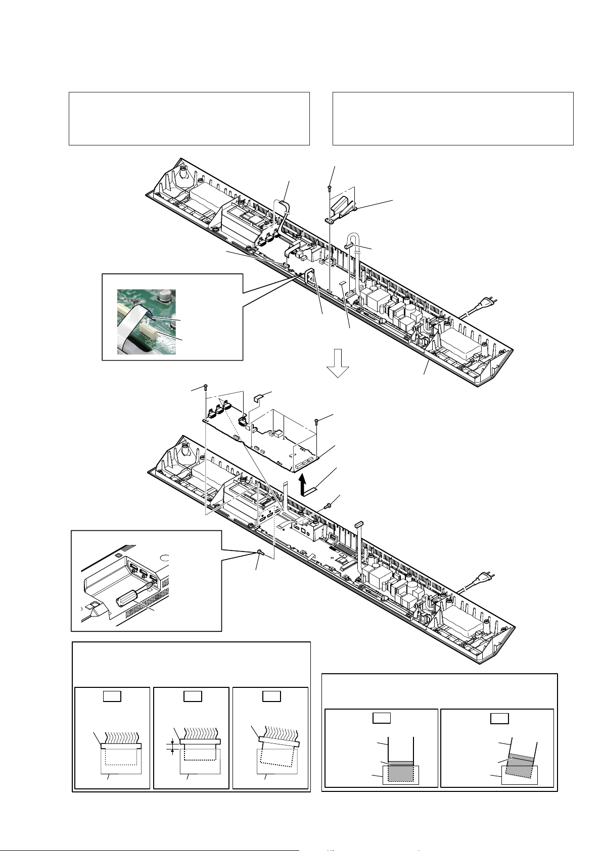
2-11. MAIN BOARD
HT-CT780
Note 1: When removing the MAIN board, you need the full length is
short screwdriver.
If that has not been available a short screwdriver, remove the
MAIN board after removing the bottom chassis block, refer to
“2-14. BOTTOM CHASSIS BLOCK” on page 20.
4 flexible flat cable
(24 core) (FFC2)
3 connector
(CN103)
)OH[LEOHIODWFDEOH))&VHWWLQJ
terminal face
connector
(CN301)
7 two screws
(BV3)
2 flexible flat cable
(14 core) (FFC1)
(CN301)
0 cushion (CZ)
Note 2: When the complete MAIN board is replaced, refer to “NOTE
OF REPLACING THE IC503 ON THE MAIN BOARD AND
THE COMPLETE MAIN BOARD” and “NOTES ON THE
WIRELESS CONNECTION (LINK) AFTER REPAIRS ARE
COMPLETE” on page 5.
5 two screws
(BVTP3 u 10)
1 connector
(CN601)
IC503
7 five screws
(BV3)
6 heat sink amp
Note 3:
spread the compound referring to “NOTE
OF REPLACING THE IC503 ON THE
MAIN BOARD AND THE COMPLETE
MAIN BOARD” on page 5.
bottom block
When you install the heat sink amp,
Please use the short screwdriver.
Note 4:
short screwdriver
–%RWWRPYLHZ–
+RZWRLQVWDOOWKHFRQQHFWRU
Insert the connector straight into the interior.
There is a possibility that using this unit without
the connector correctly installed will damage it.
OK NG NG
the interior.
connector
connector
Insert only part way.Insert straight into
connector
connector connector
connector
8 three screws
(B3 u 5)
Insert at a slant.
qa MAIN board
9 Remove the MAIN board
in the direction of the arrow.
8 screw
(B3 u 5)
+RZWRLQVWDOOWKHIOH[LEOHIODWFDEOH
When installing the flexible flat cable, ensure that
the colored line is parallel to the connector after insertion.
OK
Insert straight into the interior.
flexible flat
cable
colored line
connector
flexible flat
cable
colored line
connector
NG
Insert at a slant.
17
HT-CT780
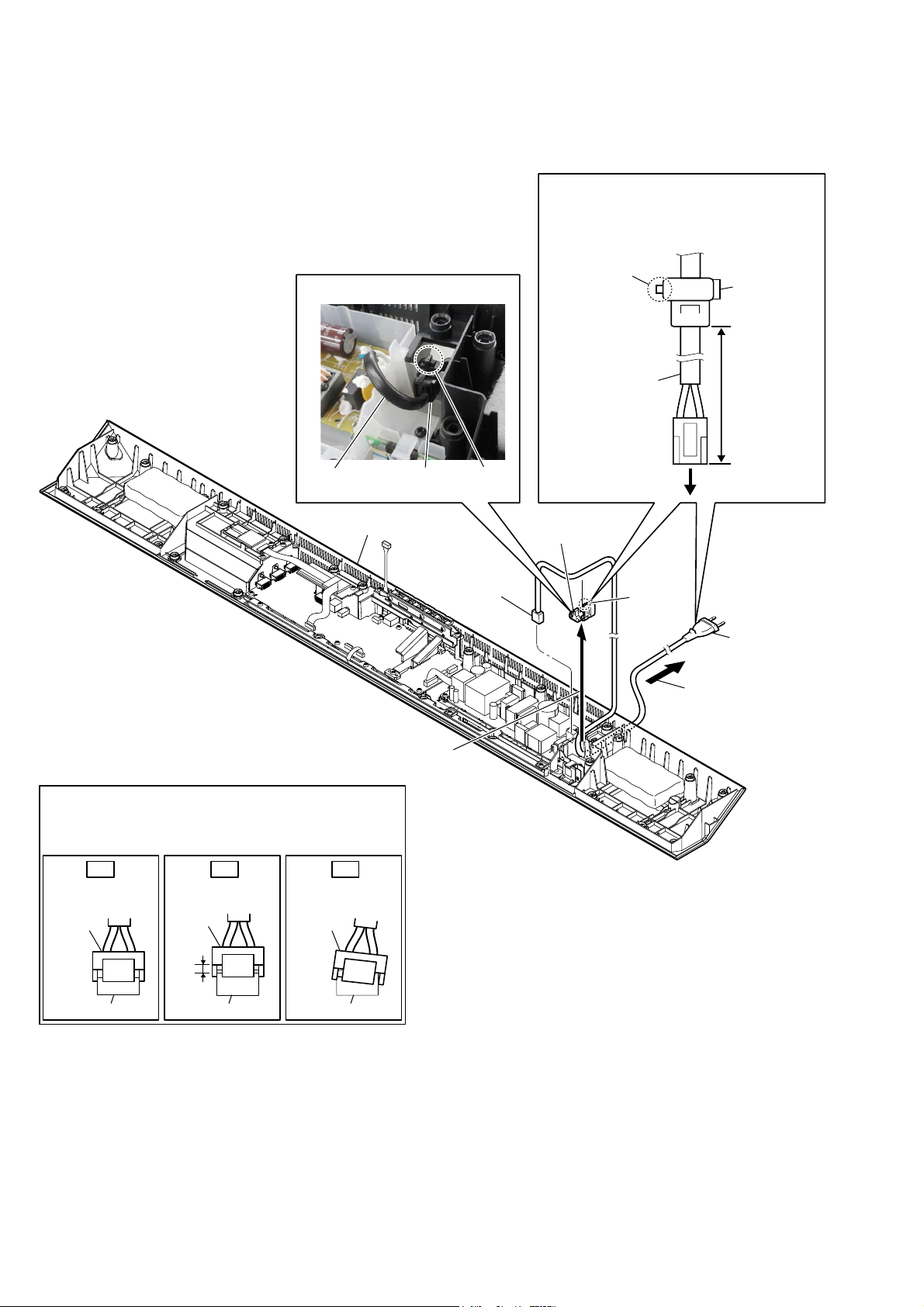
2-12. POWER CORD (AC1)
3RZHUFRUGVHWWLQJ
When installing the power cord (AC1),
Note:
check the direction of claw of cord bushing
(FBS001) and install correctly.
&RUGEXVKLQJ)%6VHWWLQJ
power cord
bottom block
cord bushing
(FBS001)
claw
1 connector
(CN901)
claw
power cord
(AC1)
to POWER board
5 cord bushing
(FBS001)
cord bushing
(FBS001)
80 +5, -0 mm
4 claw
6 power cord
(AC1)
3 Draw out the power
cord from the hole.
2 Remove the cord bushing (FBS001)
in the direction of the arrow.
+RZWRLQVWDOOWKHSRZHUFRUGFRQQHFWRU
Insert the connector straight into the interior.
There is a possibility that using this unit without
the connector correctly installed will damage it.
OK NG NG
the interior.
connector
connector
Insert only part way.Insert straight into
connector
connector connector
Insert at a slant.
connector
18
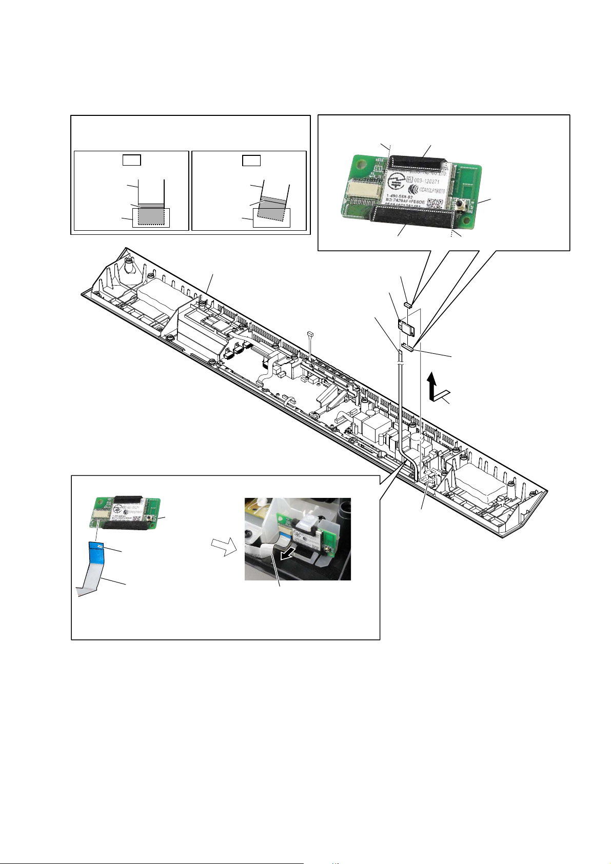
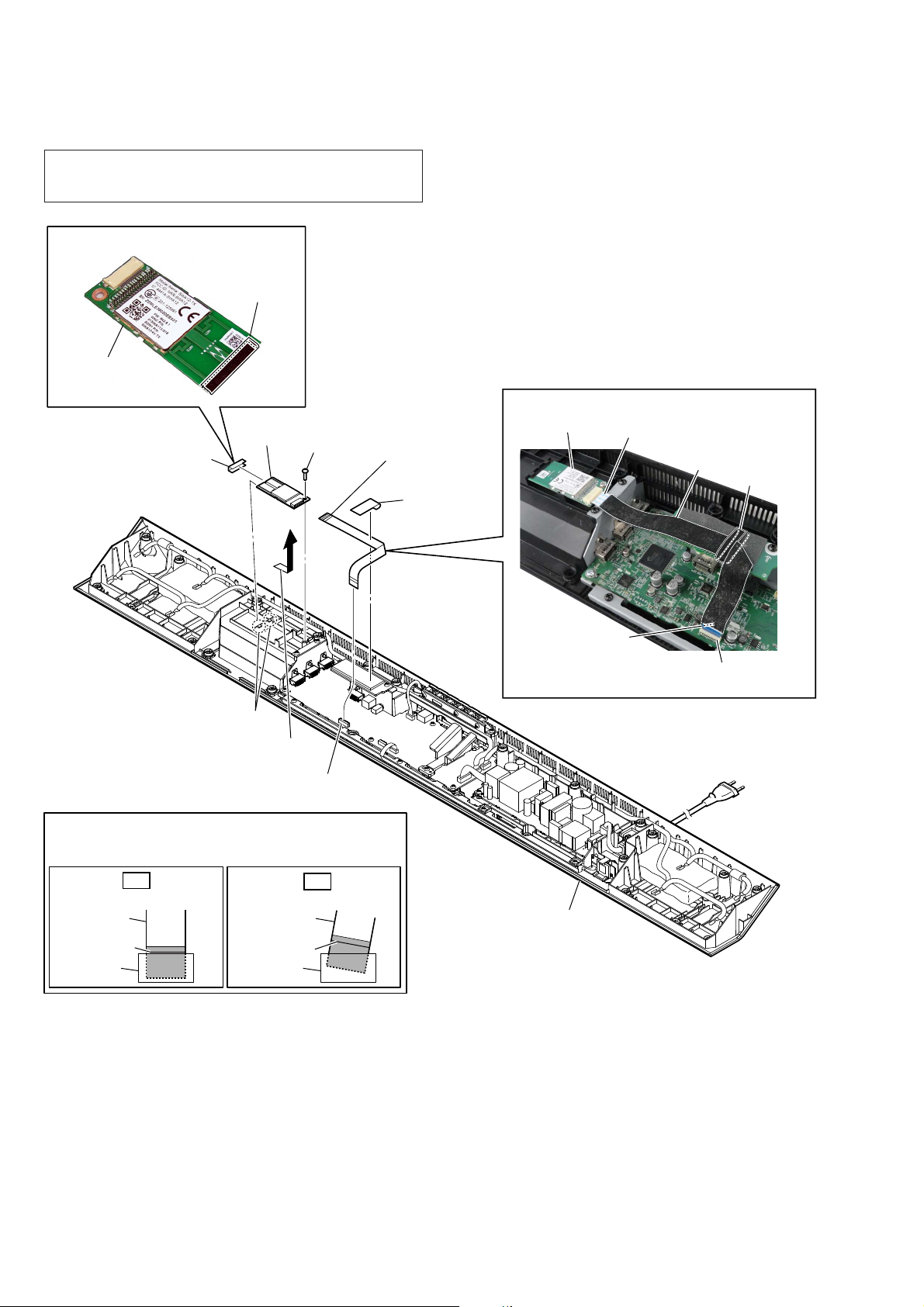
2-13. BLUETOOTH MODULE (BT1)
HT-CT780
+RZWRLQVWDOOWKHIOH[LEOHIODWFDEOH
When installing the flexible flat cable, ensure that
the colored line is parallel to the connector after insertion.
OK
Insert straight into the interior.
flexible flat
cable
colored line
connector
flexible flat
cable
colored line
connector
bottom block
NG
Insert at a slant.
3 flexible flat cable (14 core)
(FFC1)
,QVWDOODWLRQSRVLWLRQRIWKHFXVKLRQ&=DQGFXVKLRQ49$
guide line
cushion (QV, A)
4 cushion (CZ)
6 bluetooth module
(BT1)
cushion (CZ)
bluetooth module
(BT1)
guide line
5 cushion (QV, A)
2 Remove the bluetooth module
block in the direction of the arrow.
)OH[LEOHIODWFDEOH))&VHWWLQJ
bluetooth module
(BT1)
Terminal face is
below side.
flexible flat cable
(14 core) (FFC1)
Pull out the flexible flat cable
(FFC1) to the front side.
Do not pinch the flexible flat
Note:
cable (FFC1) under the
bluetooth module (BT1).
1 claw
19
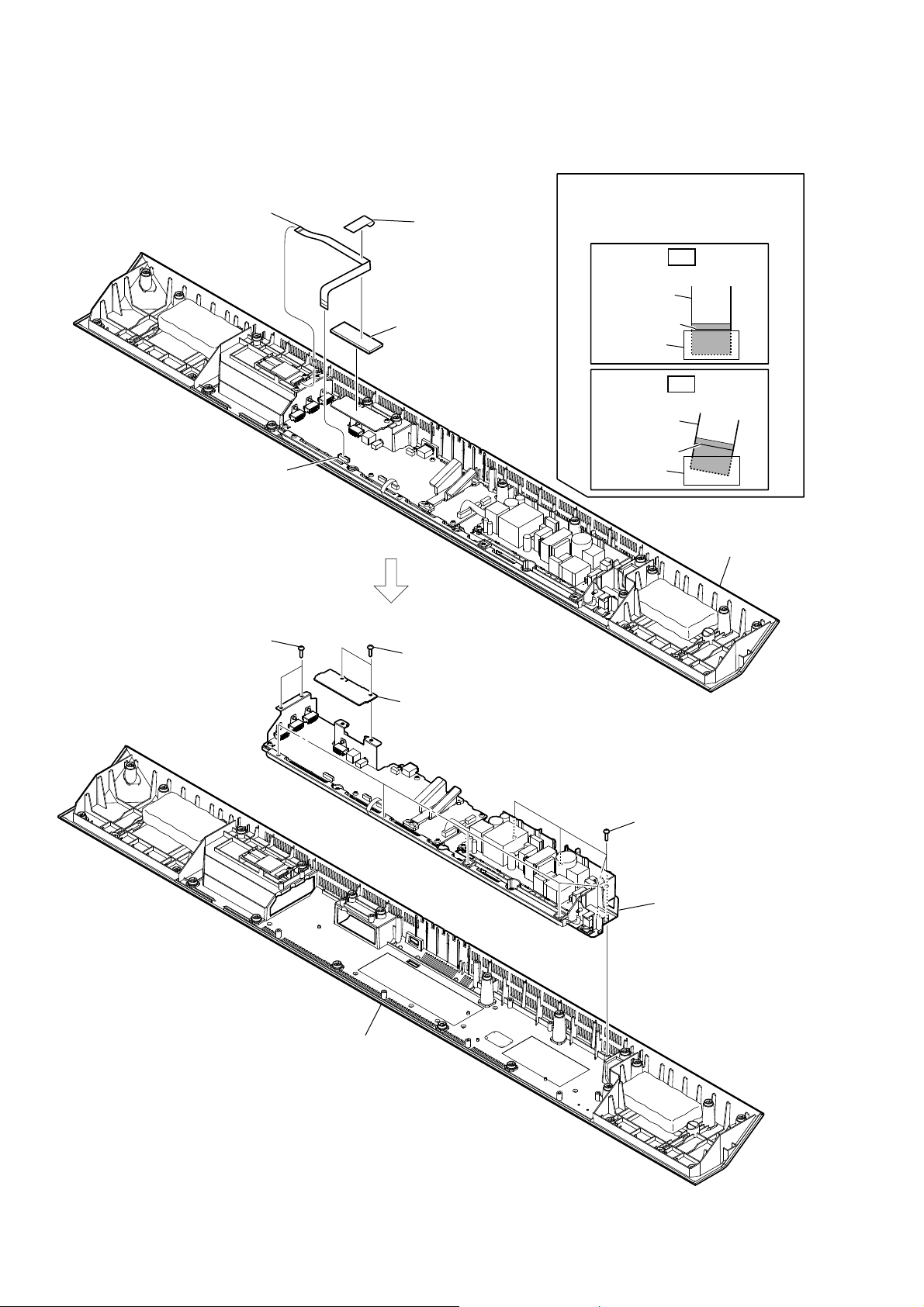
HT-CT780
2-14. BOTTOM CHASSIS BLOCK
3 flexible flat cable
(24 core) (FFC2)
2 connector
(CN103)
1 cushion (CZ)
4 cushion absorbent
How to install the flexible flat cable
When installing the flexible flat cable,
ensure that the colored line is parallel
to the connector after insertion.
OK
Insert straight into the interior.
flexible flat
cable
colored line
connector
NG
Insert at a slant.
flexible flat
cable
colored line
connector
5 two screws
(BVTP3 u 10)
bottom block
5 two screws
(BVTP3 u 10)
6 CZ3 - FFC holder board
5 eight screws
(BVTP3 u 10)
7 bottom chassis block
20
bottom panel block
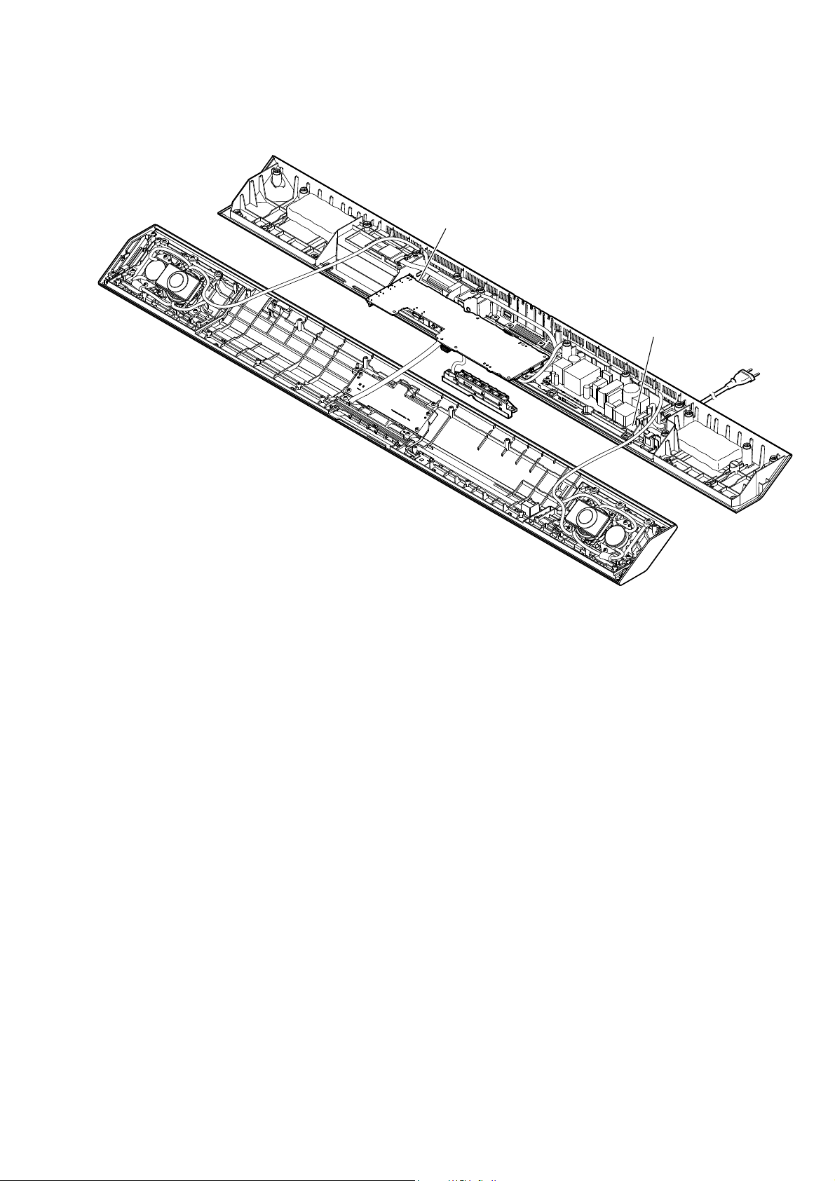
2-15. SERVICE POSITION
HT-CT780
MAIN board
POWER board
21
HT-CT780
SECTION 3
TEST MODE
1. TEST MODES OTHER THAN THE TEST MODE MENU
These are executable test mode even if not entering the test mode
menu.
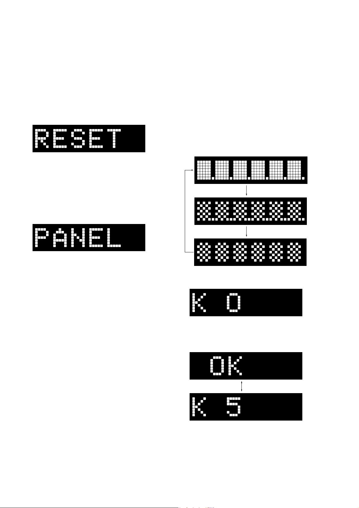
1-1. Cold Reset
It can initialize various backup information.
Procedure:
1. Press the [
2. Press the [
3. The message “RESET” is displayed on the fl uorescent indica-
tor tube, then turn the power off.
2. TEST MODES IN THE TEST MODE MENU
These are the test modes done in the test mode menu.
Setting method of the test mode menu:
1. Press the [
2. Press the two buttons of the [INPUT] and [VOLUME +] simultaneously for fi ve seconds.
3. The message “PANEL” blinks on the fl uorescent indicator
tube and enter the test mode menu.
] button to turn the power on.
?/1
] button for ten seconds.
?/1
] button to turn the power on.
?/1
2-1. Panel Test Mode
It can check the lighting of fl uorescent indicator tube and LED,
operation of buttons, display of model name, destination and software version.
Procedure:
1. Enter the test mode menu.
(Refer to “Setting method of the test mode menu”)
2. In the state of blinking the “PANEL” on the fl uorescent indica-
tor tube, press the [INPUT] button.
3. All segments in the fl uorescent indicator tube and LED (Blue-
tooth indicator) are lighted up.
4. When pressing the [VOLUME +] button, the display on the
fl uorescent indicator tube repeatedly changes in order from all
lighting → pattern 1 (Bluetooth indicator lights off) → pattern
2 (Bluetooth indicator lights up).
All lighting
Pattern 1
Releasing method of the test mode menu:
Press the [
] button to release the test mode menu.
?/1
Pattern 2
5. In the state of step 4, press the [VOLUME –] button and “K 0”
is displayed on the fl uorescent indicator tube.
Each time a button is pressed, “K 0” value increases. However,
once a button is pressed, it is no longer taken into account.
When pressing the all buttons, “OK” and “K 5” are alternately
displayed on the fl uorescent indicator tube.
22
– Continued on next page –

HT-CT780
Ver. 1.1
6. In the state of step 4, press the [INPUT] button and model
name “CT780” is displayed on the fl uorescent indicator tube.
Each time the [VOLUME +] button is pressed, the display
changes from destination → MC (-com) version → SY (system) version → UI version → TA (AMP) version → DS (DSP)
version (Not used for the servicing) → BT (Bluetooth) version
→ NF (NFC) version → HD (HDMI) version, → CE (CEC)
version → PF (platform) version → WS (wireless sound) version in this order, and returns to the model name display.
Note: Refer to the “2-5. Serial Flash Version Display Mode” and “2-6.
DSP Sound Number Display Mode” for the DS (DSP) version
on page 24.
Model name
Destination
MC version
BT version
NF version
7. When [INPUT] button is pressed while the each version is displayed on the fl uorescent indicator tube, year, month and day
of the software creation is displayed on the fl uorescent indica-
tor tube.
(Displayed values in the above fi gure are example)
When [INPUT] button is pressed again, the display returns to
the each version display.
Releasing method:
Press the [
] button to release the test mode menu.
?/1
(When the “K 0” to “K 4” is displayed on the fl uorescent indicator
tube, press the [
] button on the remote commander to release
?/1
the test mode menu)
2-2. Model Name Display Mode
It can display the model name.
Procedure:
1. Enter the test mode menu.
(Refer to “Setting method of the test mode menu” on page 22)
2. Press the [VOLUME +]/[VOLUME –] buttons to select the
model name “CT780”.
SY version
UI version
TA version
DS version
(Not used for the servicing)
HD version
CE version
PF version
WS version
(Displayed characters/values in the above fi gure are example)
Destination Display
Except AEP and UK models
AEP and UK models
NA
CE2
2-3. Destination Display Mode
It can display the destination.
Procedure:
1. Enter the test mode menu.
(Refer to “Setting method of the test mode menu” on page 22)
2. Press the [VOLUME +]/[VOLUME –] buttons to select the
destination.
(Displayed characters in the above fi gure are example)
Destination Display
Except AEP and UK models
AEP and UK models
NA
CE2
23
HT-CT780
2-4. MC Version Display Mode
It can display the MC (-com) version.
Procedure:
1. Enter the test menu.
(Refer to “Setting method of the test mode menu” on page 22)
2. Press the [VOLUME +]/[VOLUME –] buttons to select the
“MC.X.XXX” (X.XXX: MC (-com) version).
(Displayed values in the above fi gure are example)
2-5. Serial Flash Version Display Mode
It can display the SF (serial fl ash) version.
Procedure:
1. Enter the test menu.
(Refer to “Setting method of the test mode menu” on page 22)
2. Press the [VOLUME +]/[VOLUME –] buttons to select the
“SF.X.XX” (X.XX: SF (serial fl ash) version).
2-8. AMP Test Mode
(It is displayed “AMP” on the fl uorescent indicator tube)
Not used for the servicing.
Press the [
] button if having entered this mode.
?/1
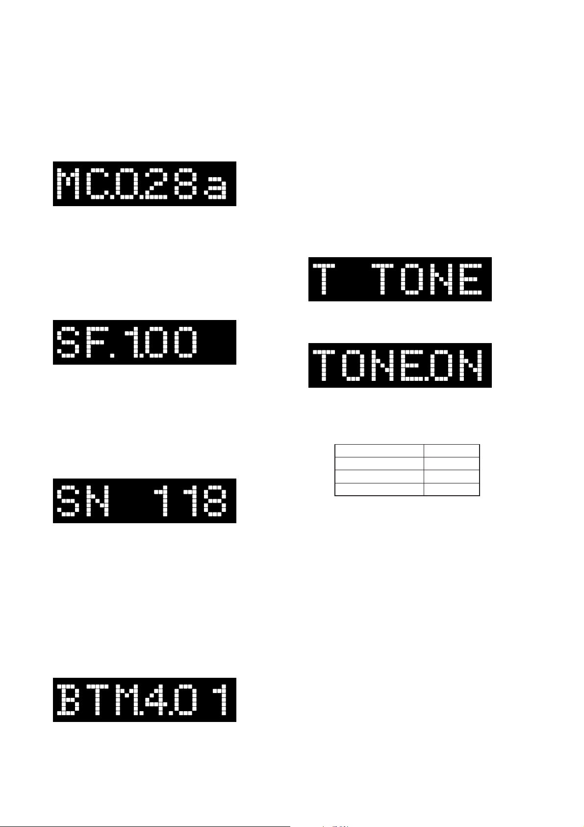
2-9. Tone Test Mode
It can check the test tone output from each speaker.
Preparation:
Connect the Bar Speaker (SA-CT780) and the Subwoofer (SAWCT780) by wireless.
Procedure:
1. Enter the test mode menu.
(Refer to “Setting method of the test mode menu” on page 22)
2. Press the [VOLUME +]/[VOLUME –] buttons to select the “T
TONE”, press the [INPUT] button.
3. The message “TONE.ON” is displayed on the fl uorescent indi-
cator tube momentarily and enter the tone test mode.
(Displayed values in the above fi gure are example)
2-6. DSP Sound Number Display Mode
It can display the SN (DSP sound number).
Procedure:
1. Enter the test menu.
(Refer to “Setting method of the test mode menu” on page 22)
2. Press the [VOLUME +]/[VOLUME –] buttons to select the
“SN XXX” (XXX: DSP sound number (000 to 998)).
(Displayed values in the above fi gure are example)
Note: “SN ---” is displayed when the information of serial fl ash is not able
to be acquired.
2-7. BT Module F/W Version Display Mode
It can display the BT (Bluetooth) module fi rmware version.
Procedure:
1. Enter the test menu.
(Refer to “Setting method of the test mode menu” on page 22)
2. Press the [VOLUME +]/[VOLUME –] buttons to select the
“BTM.X.XX” (X.XX: BT (Bluetooth) module fi rmware ver-
sion).
4. The output speaker is displayed on the fl uorescent indicator
tube. At the same time, test tone is output from speaker.
(The output speaker repeatedly changes automatically in fol-
lowing order)
Output speaker Display
Front L-ch
Front R-ch
Subwoofer
FL
FR
SW
Releasing method:
Press the [
] button to release the test mode menu.
?/1
2-10. Speaker Test Mode
(It is displayed “SPK.TST” on the fl uorescent indicator tube)
Not used for the servicing.
Press the [
] button if having entered this mode.
?/1
2-11. VACS Display Mode
(It is displayed “V. DISP” on the fl uorescent indicator tube)
Not used for the servicing.
Press the [
] button if having entered this mode.
?/1
2-12. VACS ON/OFF Mode
(It is displayed “V.ONOFF” on the fl uorescent indicator tube)
Not used for the servicing.
Press the [
] button if having entered this mode.
?/1
(Displayed values in the above fi gure are example)
24
2-13. DSP Halt Mode
(It is displayed “DSP.HLT” on the fl uorescent indicator tube)
Not used for the servicing.
Press the [
] button if having entered this mode.
?/1
 Loading...