

Sony HT-CT260H, SA-CT260H Service Manual
SERVICE MANUAL
Sony Corporation
Published by Sony Techno Create Corporation
SPECIFICATIONS
9-893-767-02
2013K33-1
©
2013.11
US Model
Canadian Model
AEP Model
UK Model
Australian Model
Ver. 1.1 2013.11
• All of the units included in the HT-CT260H
(SA-CT260H/SA-WCT260H) are required to
confi rming operation of SA-CT260H. Check
in advance that you have all of the units.
HT-CT260H
SA-CT260H
HT-CT260H
HOME THEATRE SYSTEM
SA-CT260H
ACTIVE SPEAKER SYSTEM
COMPONENT MODEL NAME
HT-CT260H
Sound Bar (Active speaker system) SA-CT260H
Subwoofer (Active Subwoofer) SA-WCT260H
• Please refer to service manual separatery issued for subwoofer.
Formats supported by this system
HDMI
Input/Output (HDMI Repeater block)
Dolby Digital
DTS
Linear PCM 2ch 48 kHz or less
Amplifier section
U.S. models:
POWER OUTPUT AND TOTAL HARMONIC
DISTORTION :
(FTC)
Front L + Front R:
With 4 ohms loads, both channels
driven, from 200 - 20,000 Hz; rated
25 Watts per channel minimum RMS
power, with no more than 1% to tal
harmonic distortion from
250 milliwatts to rated output.
POWER OUTPUT (reference)
Front L/Front R: 85 W
(per channel at 4 ohms, 1 kHz)
Canadian AEP, UK and Australian models:
POWER OUTPUT (rated)
Front L + Front R: 50 W + 50 W
(at 4 ohms, 1 kHz, 1% THD)
POWER OUTPUT (reference)
Front L/Front R: 85 W (per channel at
4 ohms, 1 kHz)
Inputs
HDMI IN
ANALOG IN
OPTICAL IN
Output
HDMI TV OUT (ARC)
BLUETOOTH section
Communication system
BLUETOOTH Specification version
3.0
Output
BLUETOOTH Specification Power
Class 2
Maximum communication range
Line of sight approx. 10 m (33 feet)
1)
Frequency band
2.4 GHz band (2.4000 GHz -
2.4835 GHz)
Modulation method
FHSS (Freq Hopping Spread
Spectrum)
Compatible BLUETOOTH profiles
2)
A2DP (Advanced Audio Distribution
Profile)
AVRCP 1.4 (Audio Video Remote
Control Profile)
Supported Codecs
3)
SBC
4)
Transmission range (A2DP)
20 Hz - 20,000 Hz (Sampling
frequency 44.1 kHz)
1) The actual range will vary depending
on factors such as obstacles between
devices, magnetic fields around a
microwave oven, static electricity,
cordless ph one, reception sensitivity,
operating system, software
application, etc.
2) BLUETOOTH standard profiles
indicate the purpose of BLUETOOTH
communication between devices.
3) Codec: Audio signal compression and
conversion format
4) Subband Codec
Front speaker un it
Speaker system
Full range speaker system,
Bass Reflex
Speaker unit
Woofer: 55 mm × 80 mm
(2 1/4 in × 3 1/4 in) cone type
Rated impedance
4 ohms
General
Power requirements
120 V AC, 60 Hz (US and Canadian models)
220 V - 240 V AC, 50/60 Hz
(AEP, UK and Australian models)
Power consumption
On: 32 W
“Control for HD MI” is off (Standby
mode):
0.5 W or less
BLUETOOTH Standby mode: 0.5 W
or less
Dimensions (approx.)
940 mm × 102 mm × 95 mm
(37 1/8 in × 4 1/8 in × 3 3/4 in)
(with stands)
940 mm × 90 mm × 100 mm
(37 1/8 in × 3 5/8 in × 4 in)
(without stands)
Mass (approx.)
2.2 kg (4 lb 13 5/8 oz)
Wireless transmitter/receiver
Frequency band
2.4 GHz band (2.404 GHz -
2.476 GHz)
Modulation method
GFSK
Design and specifications are subject to
change without notice.
s Standby power consumption: 0.5 W
or less (Sound Bar), 0.5 W or less
(Subwoofer)
File 2D
3D
Frame packing
Side-by-Side
(Half)
Over-Under
(Top-and -
Bottom)
1920 × 1080p @ 59.94/60 Hz
1920 × 1080p @ 50 Hz
1920 × 1080p @ 23.98/24 Hz
1920 × 1080i @ 59.94/60 Hz
1920 × 1080i @ 50 Hz
1280 × 720p @ 59.94/60 Hz
1280 × 720p @ 50 Hz
720 × 480p @ 59.94/60 Hz
720 × 576p @ 50 Hz
640 × 480p @ 59.94/60 Hz
This system incorporates Dolby* Digital
and t he DTS** Digital Surround System.
* Manufactured under license from
Dolby Laboratories.
Dolby, and the double-D symbol are
trademarks of Dol by Laboratories.
** Manufactured under license under
U.S. Pat ent Nos: 5,956,674; 5,974,380;
6,487,535 & other U.S. and worldwide
patents issued & pending. DTS, the
Symbol, & DTS and the Symbol
together are registered trademarks &
DTS Digital Surround and the DTS
logos are trademarks of DTS, Inc.
Product includes software. © DTS, Inc.
All Rights Reserved.
The BLUETOOTH
®
word mark and logos
are registered trademarks owned by
Bluetooth SIG, Inc. and any use of such
marks by Sony Corporation is under
license.
This system incorporates High-Definition
Multimedia Interface (HDMI™)
technology.
T
he terms HDMI and HDMI HighDefinition Multimedia Interface, and the
HDMI Logo are trademarks or registered
trademarks of HDMI Licensing LLC in the
United States and other countries.
“x.v.Color”and “x.v.Color” logo are
trade marks of Sony Corporation.
Copyrights
“WALKMAN” and “WALKMAN” logo are
registered trademarks of Sony
Corporation.
“PlayStation
®
” is a registered trademark
of Sony Computer Entertainment Inc.
Other trademarks and trade names are
those of their respective owners.
HT-CT260H
2
SAFETY CHECK-OUT
After correcting the original service problem, perform the following safety check before releasing the set to the customer:
Check the antenna terminals, metal trim, “metallized” knobs,
screws, and all other exposed metal parts for AC leakage.
Check leakage as described below.
LEAKAGE TEST
The AC leakage from any exposed metal part to earth ground and
from all exposed metal parts to any exposed metal part having a
return to chassis, must not exceed 0.5 mA (500 microamperes.).
Leakage current can be measured by any one of three methods.
1. A commercial leakage tester, such as the Simpson 229 or RCA
WT-540A. Follow the manufacturers’ instructions to use these
instruments.
2. A battery-operated AC milliammeter. The Data Precision 245
digital multimeter is suitable for this job.
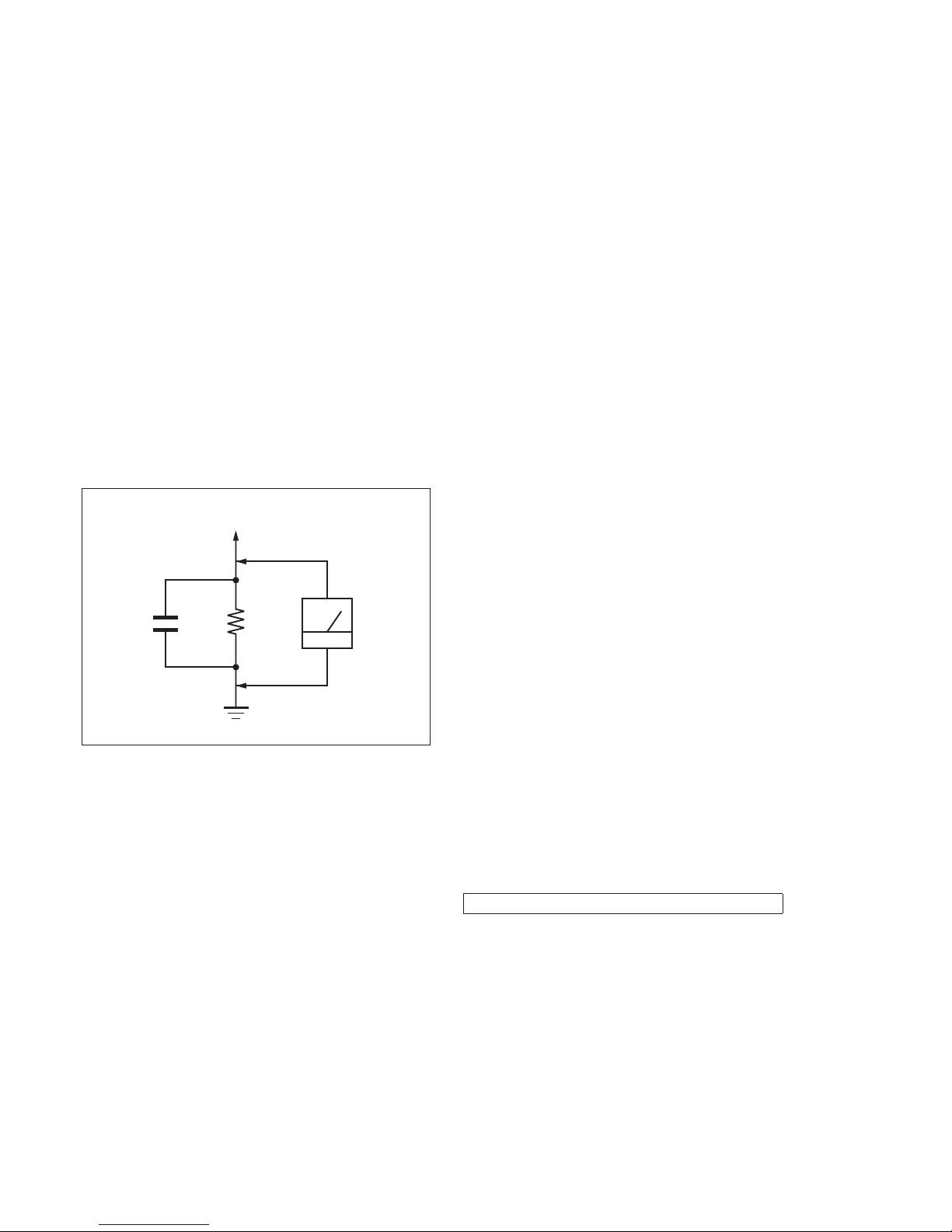
3. Measuring the voltage drop across a resistor by means of a
VOM or battery-operated AC voltmeter . The “limit” indication
is 0.75 V, so analog meters must have an accurate low-voltage
scale. The Simpson 250 and Sanwa SH-63Trd are examples
of a passive VOM that is suitable. Nearly all battery operated
digital multimeters that have a 2 V AC range are suitable. (See
Fig. A)
1.5 kΩ0.15 μF
AC
voltmeter
(0.75 V)
To Exposed Metal
Parts on Set
Earth Ground
Fig. A. Using an AC voltmeter to check AC leakage.
SAFETY-RELATED COMPONENT WARNING!
COMPONENTS IDENTIFIED BY MARK 0 OR DOTTED LINE
WITH MARK 0 ON THE SCHEMATIC DIAGRAMS AND IN
THE PARTS LIST ARE CRITICAL TO SAFE OPERATION.
REPLACE THESE COMPONENTS WITH SONY PARTS
WHOSE PART NUMBERS APPEAR AS SHOWN IN THIS
MANUAL OR IN SUPPLEMENTS PUBLISHED BY SONY.
ATTENTION AU COMPOSANT AYANT RAPPORT
À LA SÉCURITÉ!
LES COMPOSANTS IDENTIFIÉS PAR UNE MARQUE 0 SUR
LES DIAGRAMMES SCHÉMATIQUES ET LA LISTE DES
PIÈCES SONT CRITIQUES POUR LA SÉCURITÉ DE FONCTIONNEMENT. NE REMPLACER CES COMPOSANTS QUE
PAR DES PIÈCES SONY DONT LES NUMÉROS SONT DONNÉS DANS CE MANUEL OU DANS LES SUPPLÉMENTS
PUBLIÉS PAR SONY.
1. SERVICING NOTES ............................................. 3
2. DISASSEMBLY
2-1. Disassembly Flow ........................................................... 5
2-2. Seat Assy ......................................................................... 6
2-3. Cover OPT Assy, Cover HDMI Assy ............................. 6
2-4. Back Case Block ............................................................. 7
2-5. Power-supply Cord (AC1) .............................................. 8
2-6. Loudspeakers (5.5 × 8 cm) (SP1, SP2) ........................... 9
2-7. HDMI Board ................................................................... 9
2-8. MAIN Board ................................................................... 10
2-9. POWER Board ................................................................ 11
2-10. Chassis Block .................................................................. 11
2-11. Speaker Connection Cables (SPC1, SPC2) .................... 12
2-12. BT Board, VFD Board .................................................... 13
3. DIAGRAMS
3-1. Block Diagram (1/2) ....................................................... 15
3-2. Block Diagram (2/2) ....................................................... 16
3-3. Printed Wiring Board - MAIN Board - ........................... 18
3-4. Schematic Diagram - MAIN Board (1/7) - ..................... 19
3-5. Schematic Diagram - MAIN Board (2/7) - ..................... 20
3-6. Schematic Diagram - MAIN Board (3/7) - ..................... 21
3-7. Schematic Diagram - MAIN Board (4/7) - ..................... 22
3-8. Schematic Diagram - MAIN Board (5/7) - ..................... 23
3-9. Schematic Diagram - MAIN Board (6/7) - ..................... 24
3-10. Schematic Diagram - MAIN Board (7/7) - ..................... 25
3-11. Schematic Diagram - HDMI Board (1/2) - ..................... 26
3-12. Schematic Diagram - HDMI Board (2/2) - ..................... 27
3-13. Printed Wiring Board - HDMI Board - ........................... 28
3-14. Printed Wiring Board - BT Board - ................................. 29
3-15. Schematic Diagram - BT Board - ................................... 29
3-16 Printed Wiring Board - VFD Board - .............................. 30
3-17. Schematic Diagram - VFD Board - ................................ 31
3-18. Printed Wiring Board - POWER Board - ........................ 32
3-19. Schematic Diagram - POWER Board - .......................... 33
3-20. Printed Wiring Board - IR Board - .................................. 34
3-21. Schematic Diagram - IR Board - .................................... 34
4. EXPLODED VIEWS
4-1. Overall Section ............................................................... 36
4-2. Back Case Section .......................................................... 37
4-3. MAIN Board Section ...................................................... 38
4-4. Front Panel Section ......................................................... 39
5. ELECTRICAL PARTS LIST .............................. 40
Accessories are given in the last of the electrical parts list.
TABLE OF CONTENTS
Ver. 1.1
HT-CT260H
3
SECTION 1
SERVICING NOTES
ADVANCE PREPARATION WHEN CONFIRMING OPERATION
All of the units included in the HT-CT260H (SA-CT260H/SAWCT260H) are required to confi rming operation of SA-CT260H.
Check in advance that you have all of the units.
ABOUT PART REPAIR OF EACH BOARD
When mounted parts on each board installed by this unit are defective, replace the complete mounted board.
However the U701 on the MAIN board is exchangeable. Refer to
“ELECTRICAL PARTS LIST” (page 40) for U701.
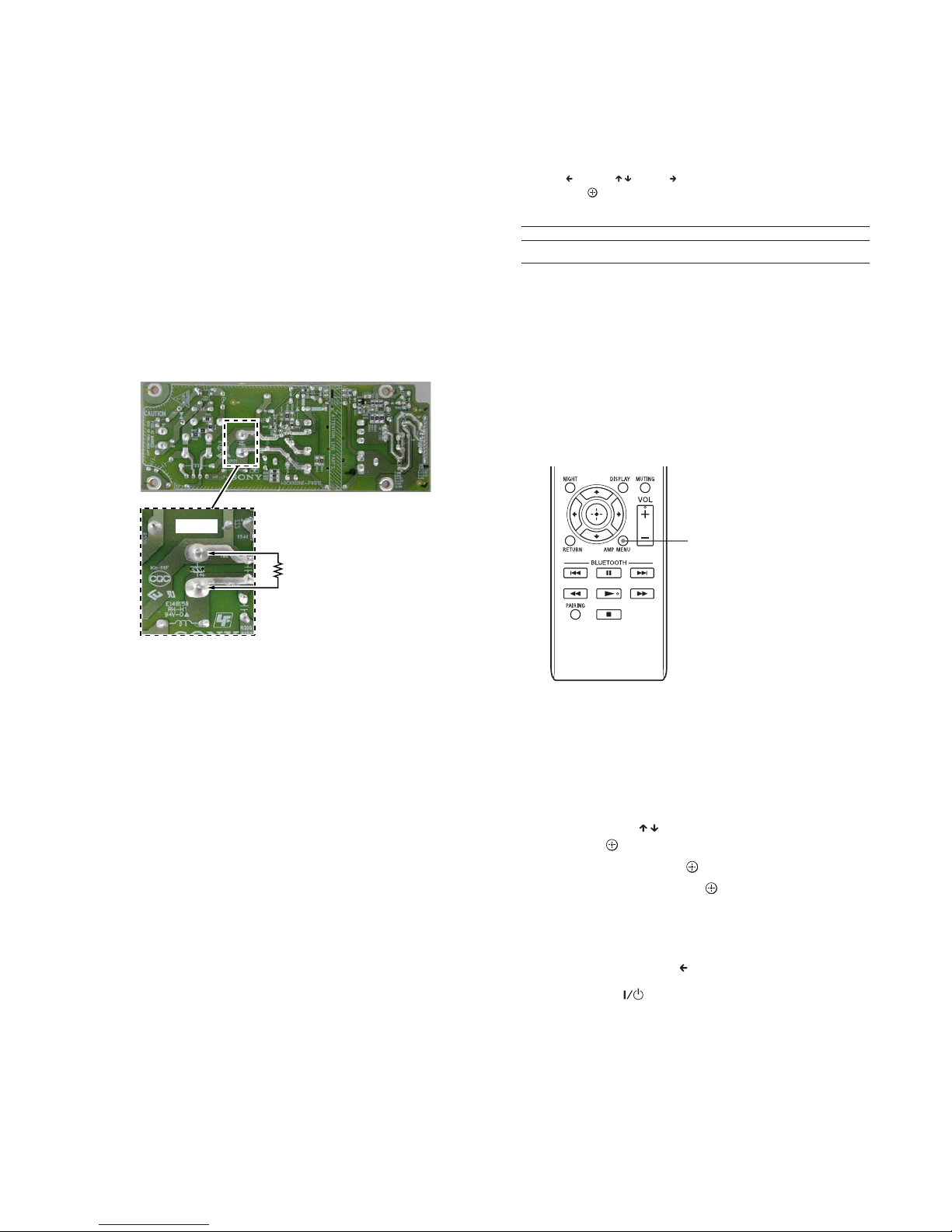
CAPACITOR ELECTRICAL DISCHARGE PROCESSING
When checking the board, for the electric shock prevention, connect the resistors to both ends of respective capacitor (CE502) to
discharge the capacitor (CE502).
– POWER Board (Conductor Side) –
CE502
800 :
2 W
SOFTWARE VERSION DISPLAY
You can set the following items with AMP MENU on the remote control.
Your settings are retained even if you disconnect the AC power cord (mains lead).
1 Press AMP MENU to turn on the AMP menu.
2
Press (return) / (select)/ (proceed) repeatedly to select the item
and press to decide the setting.
3
Press AMP MENU to turn off the AMP menu.
SYSTEM
VERSION The current firmware version information appears on the
front panel display.
Menu items Function
NOTE OF REPLACING THE WS T BOARD
When the WS T board is exchanged, you must perform linking
between SA-CT260H and SA-WCT260H.
Linking method:
This operation requires a remote commander.
You can link the Sound Bar (SA-CT260H)
and the subwoofer (SA-WCT260H) again
to enable wireless transmission between
them.
1
Press LINK on the rear of the
subwoofer with the point of a
pen, etc .
The subwoofer keeps beeping for
a certain time. Perform steps 2 to 5
before the subwoofer stops
beeping.
2 Press AMP MENU.
3
Select “WS” with (select),
then press .
4
Select “LINK,” then press .
5 “START” appears, then press .
“SEARCH” appears, and the Sound
Bar searches for equipment that
can be used with Link. Proceed to
the next step within 1 minute.
To quit the Link function during a
search for equipment, press
.
When subwoofer is linked with the
Sound Bar, the
indicator on
the subwoofer lights up in green
and the subwoofer beeps once.
“OK” appears on the front panel
display.
If “FAILED” appears or the
subwoofer does not stop beeping,
perform the process again from
ste p 1.
6
Press AM P MENU.
The AMP menu turns off.
AMP
MEN U
Ver. 1.1
HT-CT260H
4
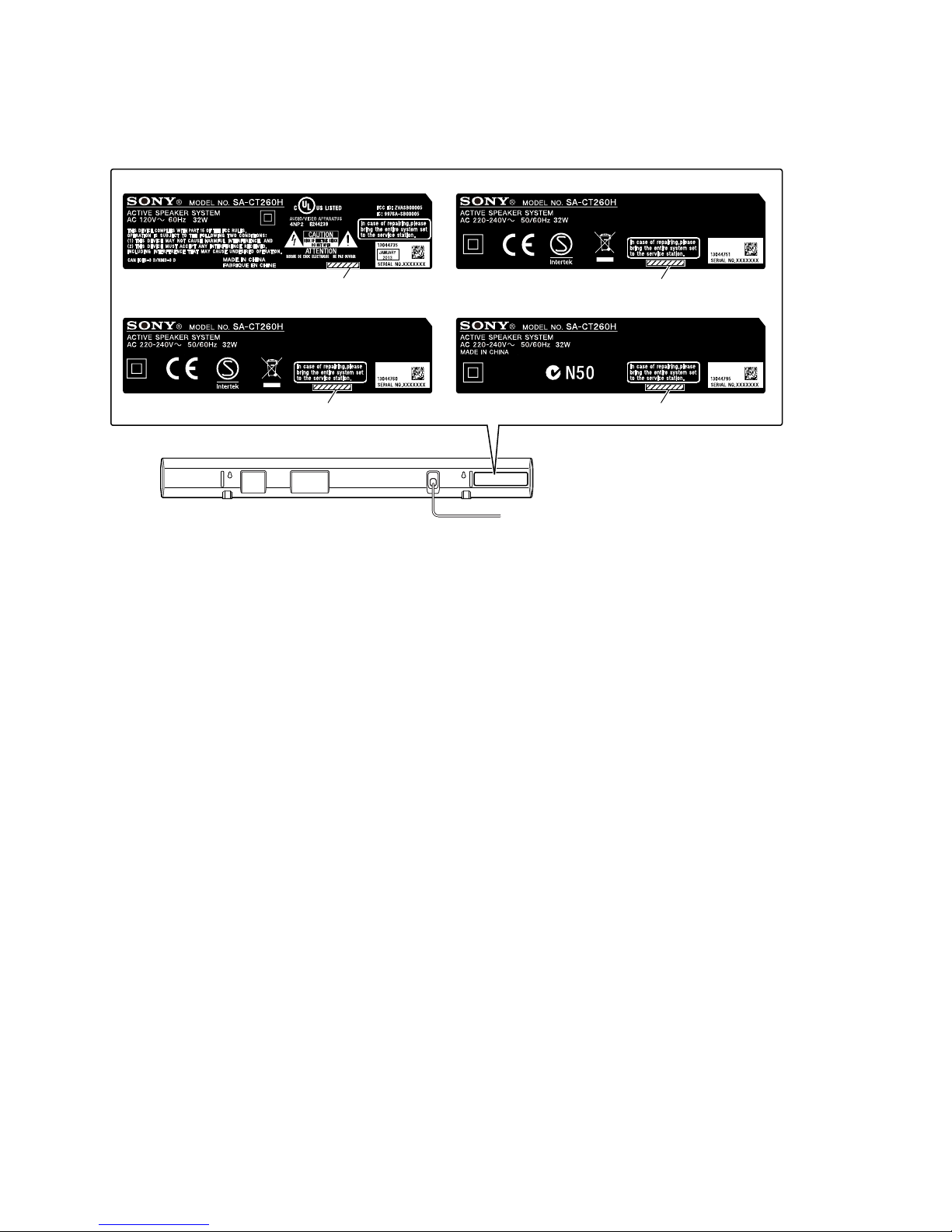
MODEL IDENTIFICATION
Distinguish by model number label stuck on the rear side of a main unit.
– Rear view –
MODEL NUMBER LABEL
US and Canadian models AEP model
UK model Australina model
4-463-506-0s
4-463-507-0s
4-463-508-0s 4-463-509-0s
HT-CT260H
5
SECTION 2
DISASSEMBLY
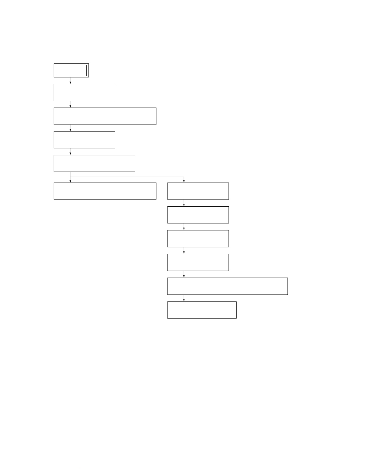
• This set can be disassembled in the order shown below.
2-1. DISASSEMBLY FLOW
SET
2-7. HDMI BOARD
(Page 9)
2-8. MAIN BOARD
(Page 10)
2-9. POWER BOARD
(Page 11)
2-10. CHASSIS BLOCK
(Page 11)
2-11. SPEAKER CONNECTION CABLES (SPC1, SPC2)
(Page 12)
2-12. BT BOARD, VFD BOARD
(Page 13)
2-2. SEAT ASSY
(Page 6)
2-3. COVER OPT ASSY, COVER HDMI ASSY
(Page 6)
2-4. BACK CASE BLOCK
(Page 7)
2-5. POWER-SUPPLY CORD (AC1)
(Page 8)
2-6. LOUDSPEAKERS (5.5 × 8 cm) (SP1, SP2)
(Page 9)
HT-CT260H
6
Note: Follow the disassembly procedure in the numerical order given.
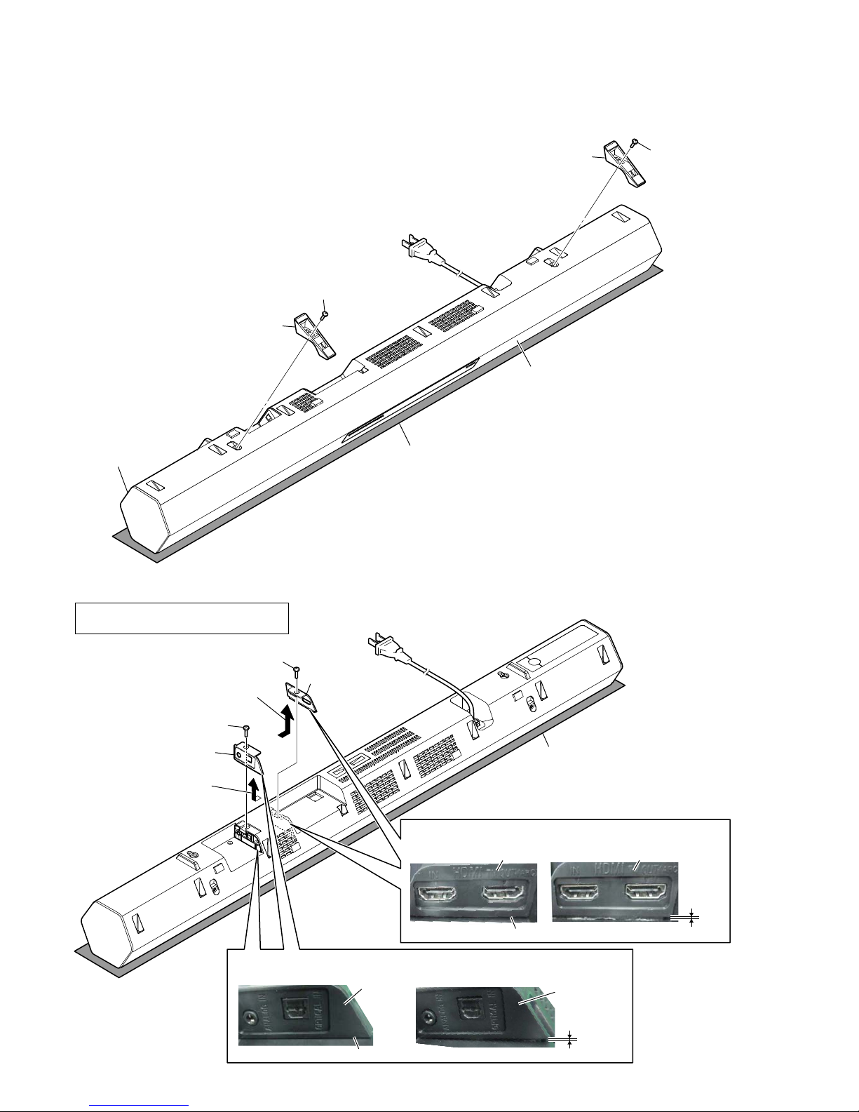
2-2. SEAT ASSY
2 seat assy
2 seat assy
1 screw
(PTT3 u 6)
1 screw
(PTT3 u 6)
front side
rear side
– Bottom view –
Note:
Please spread a sheet under
a unit not to injure grill side.
2-3. COVER OPT ASSY, COVER HDMI ASSY
2 Remove the cover OPT assy
in the direction of a arrow.
5 Remove the cover HDMI assy
in the direction of a arrow.
3 cover OPT assy
6 cover HDMI assy
1 screw
(BTP3 u 8)
4 screw
(BTP3 u 8)
– Rear bottom view –
NGOK
NGOK
cover
OPT assy
No gap.
cover HDMI assy cover HDMI assy
cover
OPT assy
&RYHU237DVV\VHWWLQJ
&RYHU+'0,DVV\VHWWLQJ
There is a gap.
There is a gap.
Note 2:
Please spread a sheet under
a unit not to injure grill side.
Note 1:
cover OPT assy and cover HDMI assy
can be removed from either.
No gap.
HT-CT260H
7
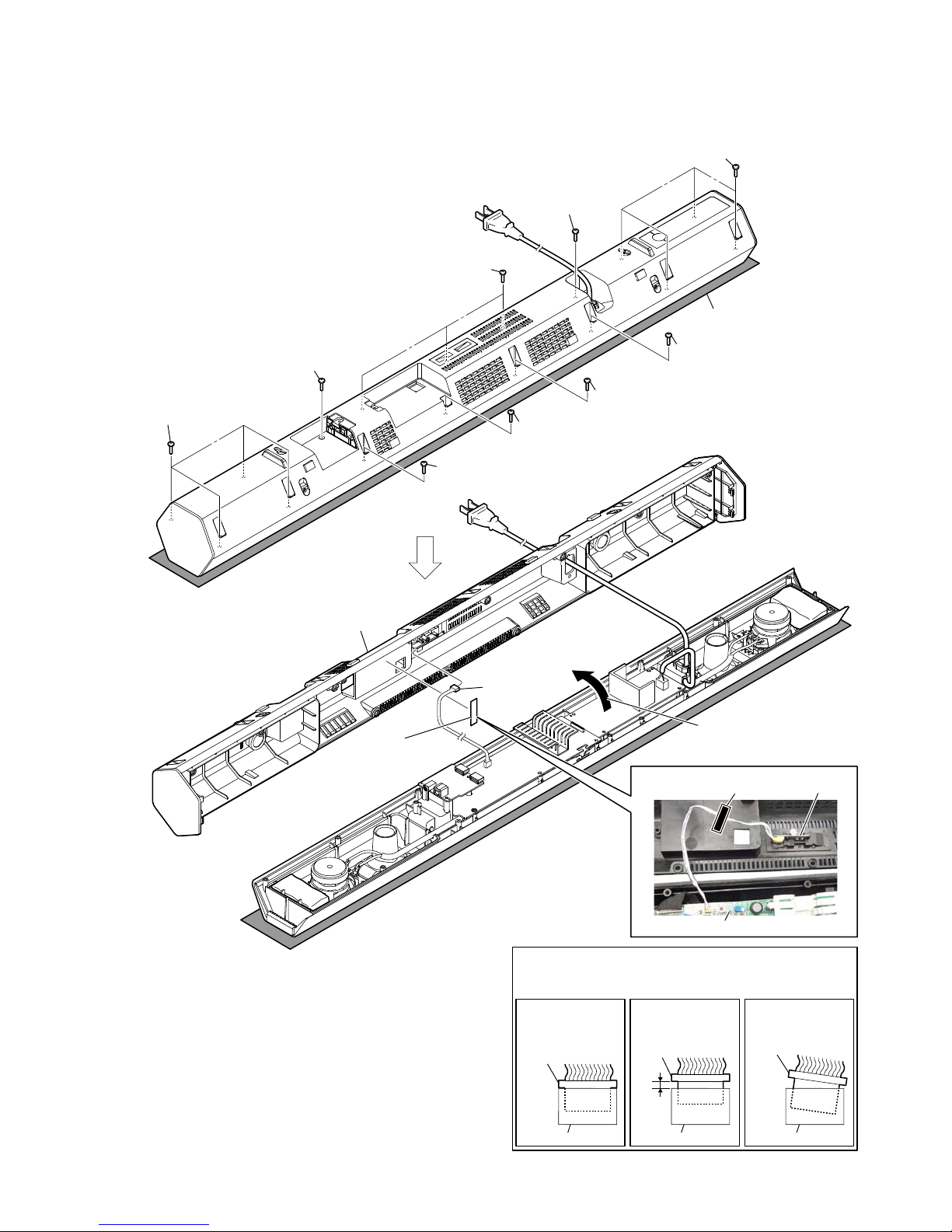
2-4. BACK CASE BLOCK
1 screw
(P3.5 u 12)
1 screw
(P3.5 u 12)
1 four screws
(P3.5 u 12)
1 four screws
(P3.5 u 12)
1 screw
(P3.5 u 12)
– Rear bottom view –
Note 1:
Please spread a sheet under
a unit not to injure grill side.
2 Remove the back case block
in the direction of a arrow.
5 back case block
4 connector
(XP4)
3 cushion
cushion
MAIN board
IR board
1 three screws
(P3.5 u 12)
1 screw
(P3.5 u 12)
1 screw
(P3.5 u 12)
1 screw
(P3.5 u 12)
Note 2:
When you install the connector, please install them correctly.
There is a possibility that this machine damages when not
correctly installing it.
Insert is shallow
Insert is straight
to the interior.
connector
Insert is incline
connector
connector
connector
connector connector
NGOK NG
:ire VettiQJ
HT-CT260H
8
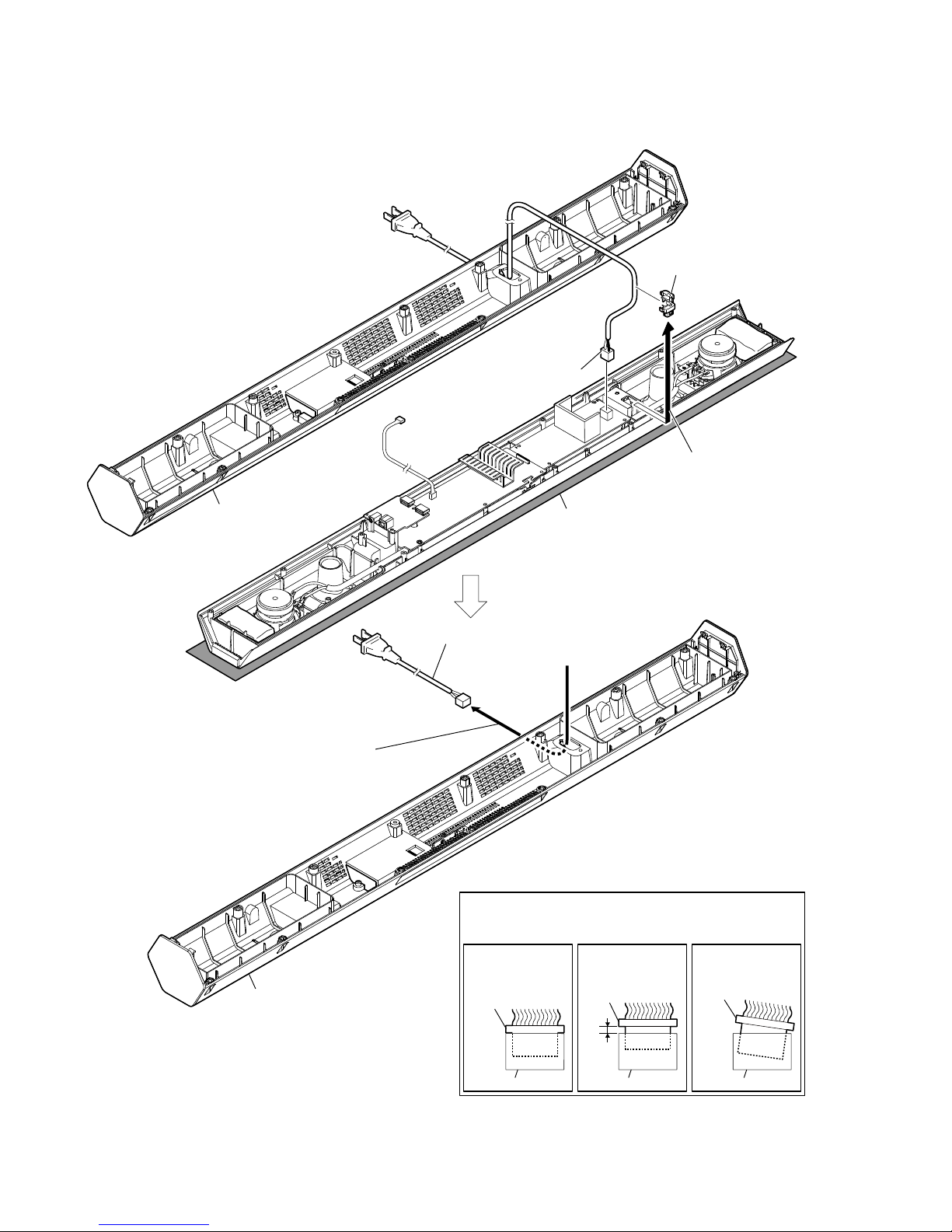
2-5. POWER-SUPPLY CORD (AC1)
5 power-supply cord (AC1)
Note 2:
When you install the connector, please install them correctly.
There is a possibility that this machine damages when not
correctly installing it.
Insert is shallow
Insert is straight
to the interior.
connector
Insert is incline
connector
connector
connector
connector connector
NGOK NG
– Rear bottom view –
3 cord bush
1 power-supply cord
connector
(CON50)
4 Draw out the power-supply cord (AC1)
from the back case block.
Note 1:
Please spread a sheet under
a unit not to injure grill side.
back case block
2 Remove the cord bush
in the direction of a arrow.
back case block
HT-CT260H
9
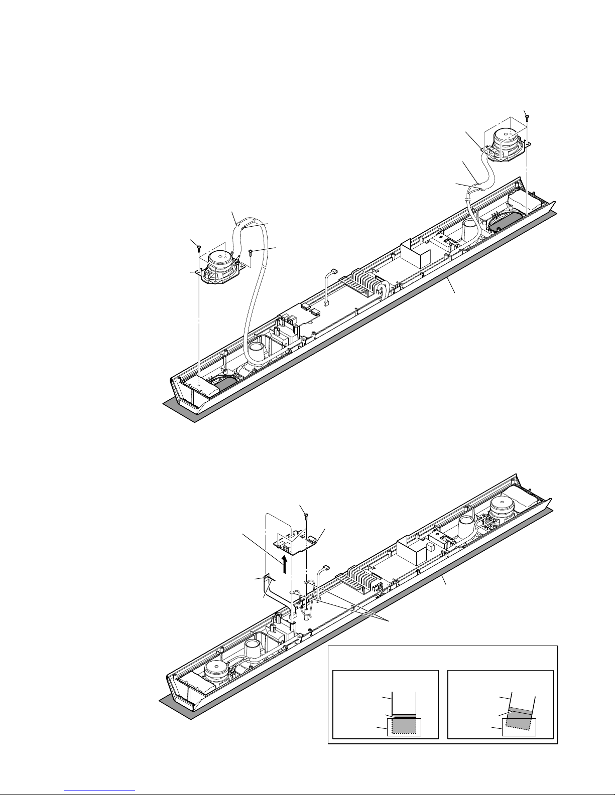
2-6. LOUDSPEAKERS (5.5 × 8 cm) (SP1, SP2)
Note:
Please spread a sheet under
a unit not to injure grill side.
– Rear bottom view –
3 loudspeaker (5.5 u 8 cm)
(SP1) (L-ch)
2 four tapping screws
(BTP3 u 8)
1 terminal (wide side)
[red]
1 terminal (wide side)
[red]
1 terminal (narrow side)
[black]
1 terminal (narrow side)
[black]
2 four tapping screws
(BTP3 u 8)
2 tapping screw
(BTP3 u 8)
3 loudspeaker (5.5 u 8 cm)
(SP2) (R-ch)
2-7. HDMI BOARD
1 flexible flat cable (24P) (FFC1)
Note 2:
When installing the
flexible flat cable
(24P) (FFC1), insert in the correct
orientation after confirming the terminal
face.
terminal
face
2 three screws
(BTP3 u 8)
5 HDMI board
4 two earth lugs
3 Remove the HDMI board in
the direction of an arrow.
– Rear bottom view –
Note 1:
Please spread a sheet under
a unit not to injure grill side.
Note 3:
When installing the flexible flat cable,
ensure the colored line.
No slanting after insertion.
colored line
colored line
Insert is straight to the interior. Insert is incline
flexible flat
cable
flexible flat
cable
connectorconnector
OK
NG

HT-CT260H
10
2-8. MAIN BOARD
– Rear top view –
Note 1:
Please spread a sheet under
a unit not to injure grill side.
7 screw
(BTP3 u 8)
7 screw
(BTP3 u 8)
9 MAIN board
Note 5:
When installing the flexible flat cable,
ensure the colored line.
No slanting after insertion.
Note 3:
Arrange the wire so as not to
protrude to the outside of the
front panel.
Note 4:
Check that the connector has fitted in firmly.
colored line
colored line
Insert is straight to the interior. Insert is incline
flexible flat
cable
flexible flat
cable
connectorconnector
MAIN board
OK
NG
5 connector
(XP8)
4 connector
(XP3)
6 connector
(XP9)
8 connector
(XP10)
7 screw
(BTP3 u 8)
7 screw
(BTP3 u 8)
3 flexible flat cable
(18P) (XP5)
1 flexible flat cable (24P) (FFC1) (CN2)
Note 2:
When installing the
flexible flat cable
(24P) (FFC1) (CN2), insert in the correct
orientation after confirming the terminal
face.
terminal
face
Note 6:
When you install the connector, please install them correctly.
There is a possibility that this machine damages when not
correctly installing it.
Insert is shallow
Insert is straight
to the interior.
connector
Insert is incline
connector
connector
connector
connector connector
NGOK NG
Wire setting
Note 3:
Arrange the wire so as not to protrude to the outside of the
front panel.
Wire setting
NG
OK
&onneFtor setting
2 cushion
MAIN board
Connectors are not
firmly in place.
MAIN board
flexible flat cable (24 core)
flexible flat cable (24 core)
cushion
Connectors are
firmly in place.
HT-CT260H
11
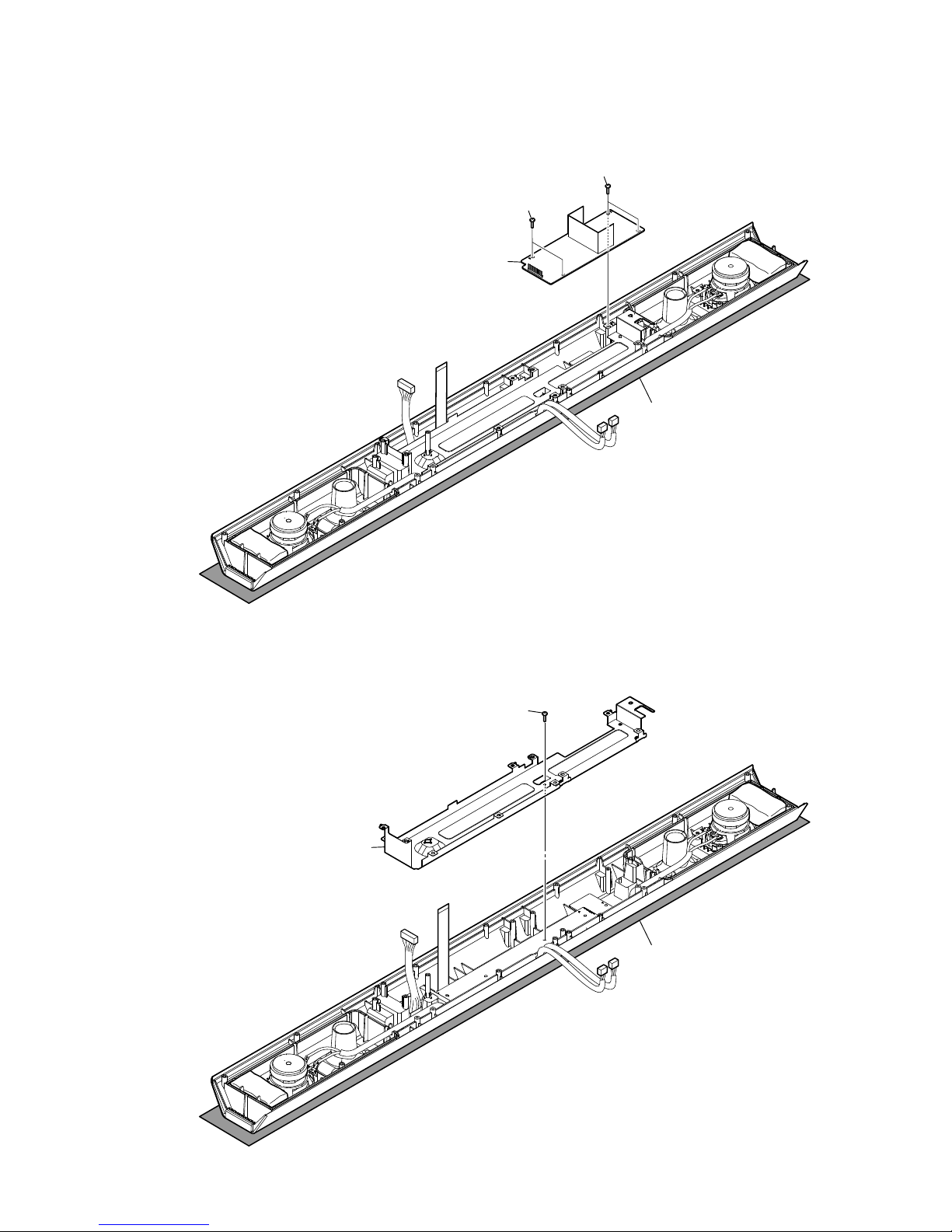
2-9. POWER BOARD
2 POWER board
1 two screws
(BTP3 u 8)
1 two screws
(BTP3 u 8)
Note:
Please spread a sheet under
a unit not to injure grill side.
– Rear bottom view –
2-10. CHASSIS BLOCK
1 screw
(BTP3 u 8)
2 chassis block
Note:
Please spread a sheet under
a unit not to injure grill side.
– Rear bottom view –
HT-CT260H
12
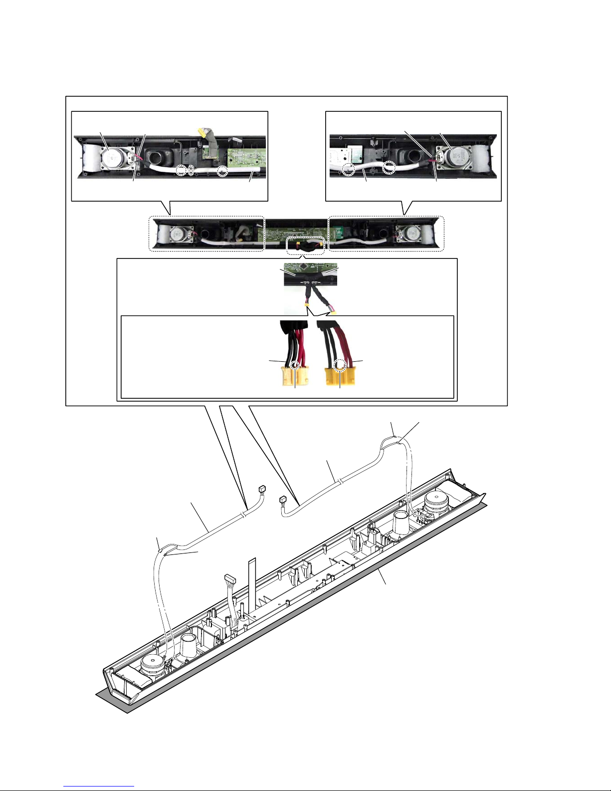
2-11. SPEAKER CONNECTION CABLES (SPC1, SPC2)
– Rear bottom view –
– Front panel block inner view –
2 speaker connection cable
(SPC2) (R-ch)
2 speaker connection cable
(SPC1) (L-ch)
speaker connection cable
(SPC2) (R-ch)
speaker connection cable
(SPC2) (R-ch)
speaker connection cable
(SPC1) (L-ch)
speaker connection cable
(SPC1) (L-ch)
Speaker connection cables setting
loudspeaker (5.5 u 8 cm)
(SP2) (R-ch)
loudspeaker (5.5 u 8 cm)
(SP2) (R-ch)
1 terminal (wide side)
[red]
[red] (wide side)
[red] (wide side)
1 terminal (wide side)
[red]
1 terminal (narrow side)
[black]
1 terminal (narrow side)
[black]
[black] (narrow side)
[black] (narrow side)
Note 1:
Please spread a sheet under
a unit not to injure grill side.
speaker connection cable
(SPC2) (R-ch)
speaker connection cable
(SPC1) (L-ch)
Blank.No blank.
Note 2:
When installing speaker connection
cables, check the form of a connector,
in order not to mistake right and left.
HT-CT260H
13
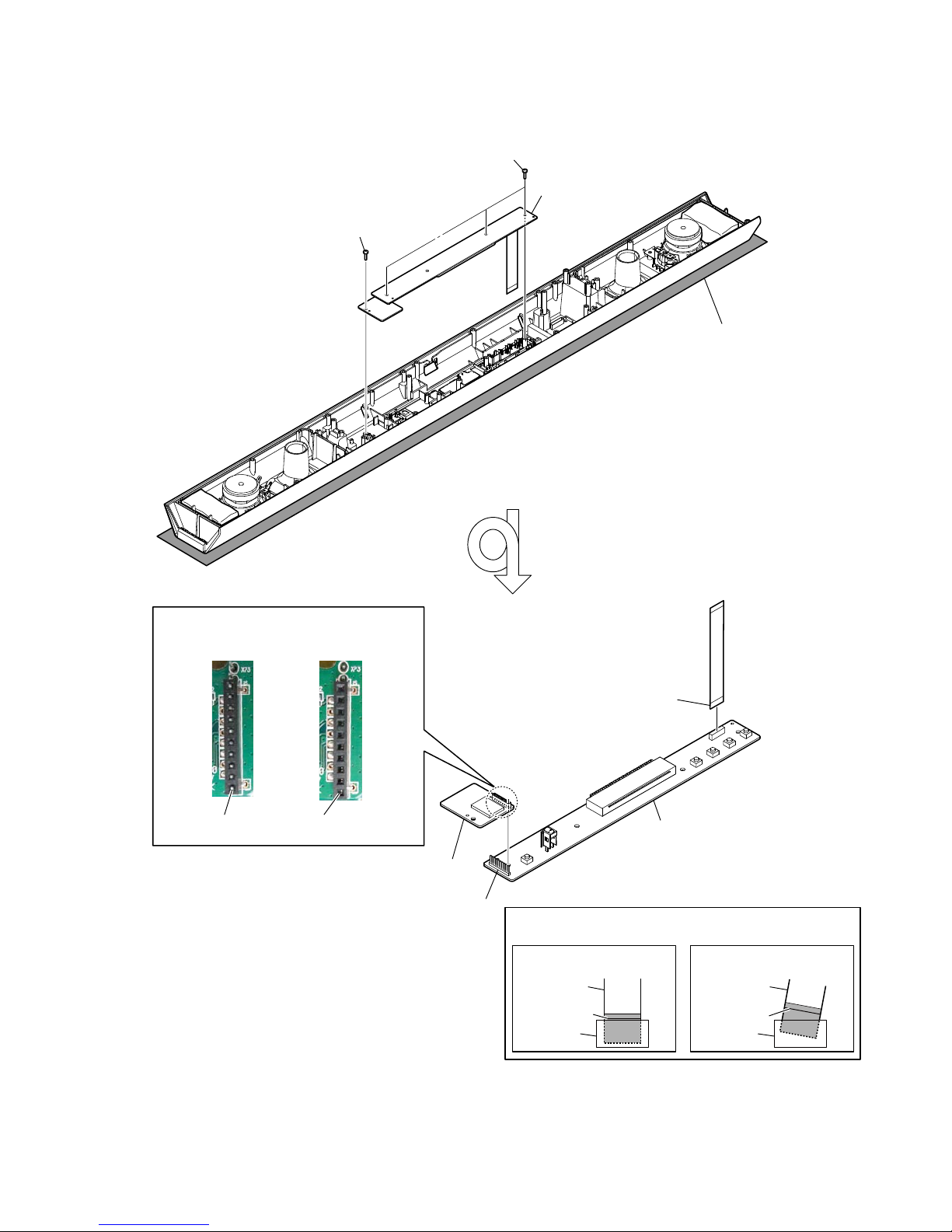
2-12. BT BOARD, VFD BOARD
2 VFD board block
1 three screws
(BTP3 u 8)
1 screw
(BTP3 u 8)
5 flexible flat cable (18P)
(FFC2) (XP5)
– Rear bottom view –
Note 1:
Please spread a sheet under
a unit not to injure grill side.
Note 3:
When installing the flexible flat cable,
ensure the colored line.
No slanting after insertion.
colored line
colored line
Insert is straight to the interior. Insert is incline
flexible flat
cable
flexible flat
cable
connectorconnector
OK
NG
NGOK
4 BT board
6 VFD board
3 connector
(XP9)
Note 2:
Check that the connector has fitted in firmly.
&oQQeFtor VettiQJ
Connectors are not
firmly in place.
Connectors are
firmly in place.
 Loading...