

Page 1
Interactive
Remote
Commander
4-249-351-11(1)
Operating Instructions
Mode d’emploi
Owner’s Record
The model and serial numbers are located on the rear of the unit. Record the serial
number in the space provided below. Refer to them whenever you call upon your Sony
dealer regarding this product.
Model No. Serial No.
GB
FR
RM-TP2
© 2003 Sony Corporation
Page 2

WARNING
For customers in the United States
WARNING
This equipment has been tested and found to comply
with the limits for a Class B digital device, pursuant
to Part 15 of the FCC Rules.
These limits are designed to provide reasonable
protection against harmful interference in a residential
installation. This equipment generates, uses, and can
radiate radio frequency energy and, if not installed
and used in accordance with the instructions, may
cause harmful interference to radio communications.
However, there is no guarantee that interference will
not occur in a particular installation. If this
equipment does cause harmful interference to radio or
television reception, which can be determined by
turning the equipment off and on, the user is
encouraged to try to correct the interference by one or
more of the following measures:
– Reorient or relocate the receiving antenna.
– Increase the separation between the equipment and
control amplifier.
– Connect the equipment into an outlet on a circuit
different from that to which the control amplifier is
connected.
– Consult the dealer or an experienced radio/TV
technician for help.
CAUTION
You are cautioned that any changes or modifications
not expressly approved in this manual could void
your authority to operate this equipment.
For customers in Canada
This Class B digital apparatus complies with
Canadian ICES-003.
If you have any questions about this product, you may
call; Sony Customer Information Services Center 1-800222-7669.
The Number below is for the FCC related matters only.
Regulatory Information
Declaration of Conformity
Trade name: SONY
Model No.: RM-TP2
Responsible Party: Sony Electronics Inc.
Address: 680 Kinderkamack Road, Oradell,
Telephone No.: 201-930-6972
This device complies with Part 15 of the FCC
Rules. Operation is subject to the following two
conditions:
(1) This device may not cause harmful
interference, and (2) this device must accept any
interference received, including interference that
may cause undesired operation.
GB
2
NJ. 07649 USA
Page 3

Table of Contents
Features ................................................. 4
Preparations
Compatible components and functions .....
Preparing the commander......................5
Screen hierarchy .................................... 7
Location of Parts and
Controls
Front panel.............................................8
Rear panel..............................................9
Basic Operations
Registering the components ................10
Operating the components...................12
Operations for Sony
Amplifiers/Receivers
Operating the amplifier/receiver ......... 19
2 Way Remote Operations
Operating the amplifier/receiver ......... 21
Operating the tuner .............................. 22
Operating the CD player or MD deck ....
22
Advanced Operations
Performing several commands in
5
sequence automatically
(Macro Play).................................. 23
Learning the commands of other remote
commanders ..................................26
Switching the input on the amplifier/
receiver automatically
(AMP LINK) ................................. 29
Changing the name of the remote
(component) ..................................29
Adjusting the commander’s operating
environment .................................. 30
Additional Information
Safety regulations ................................ 32
Precautions .......................................... 34
Troubleshooting................................... 35
Specifications ......................................36
Maker compatibility list ......................37
GB
GB
3
Page 4
Features
The RM-TP2 Interactive Remote Commander provides centralized control of all your AV
components from a single remote commander and saves you the trouble of operating different AV
components with different remote control devices. Its main features are as follows:
Centralized control of Sony AV components with this one remote
commander
This Commander is preset to operate Sony brand components, so you can use it right out of the
box as a control center for your Sony AV components. This Commander also incorporates a
variety of operations especially for Sony amplifiers/receivers (page 19).
2 way remote operations
This Commander is of a 2 way remote system. You can operate Sony 2 way components (with
Control A1/A1
Preset remote control signals for non-Sony components
This Commander also contains presets for most other major component manufacturers. You can
remote control your components by registering them (page 10).
Macro Play Function for one-touch operation of several commands
You can program the Commander to execute a series of operations (up to 24 steps) from a single
key (page 22). You can program up to 16 Macro Plays.
Learning Function for programming additional remote control signals
This Commander has a Learning Function, to learn the signals from other remotes and operate
non-preset components or functions (page 26). The Learning Function can be used with preset
operation keys and USER RESERVE KEYS.
Easy-to-operate touch sensitive LCD and the jog dial
This Commander has a touch sensitive LCD that displays operation keys according to the selected
component. You can operate components by touching the displayed keys or turning the jog dial.
The display backlight allows operation even in the dark.
Name Editing Function for remote (component) names and MACRO names
You can edit the remotes (components) names and the Macro Play names (pages 24 and 29). This
function is useful for distinguishing each component or Macro Play.
Frequently used amplifier/receiver and TV control buttons are on the front
panel
The frequently used amplifier/receiver and TV control buttons are located on the front panel, so
that you can easily operate the amplifier/receiver and TV while operating other AV components.
control system) with this Commander (page 20).
GB
4
Page 5

Preparations
This chapter describes how to prepare the
remote commander for operation. Be sure to
read this section before operating.
Compatible components
and functions
This unit is a remote control system that
utilizes infrared rays to control amplifiers/
receivers and AV components.
Compatible Components
This unit can be used to operate Sony AV
components as well as AV components made
by other manufacturers. Setup is necessary in
order to operate components made by other
manufacturers (page 10).
Note
Depending on the component, control may not be
possible using this unit.
Functions
This commander operates under the 1 way and
the 2 way remote system. As a 2 way remote
commander, you can operate the Sony
components compatible with the 2 way remote
system. Under the 2 way remote system, not
only does it transmit infrared rays for operation
of the amplifier/receiver, it also receives
infrared rays emitted by the amplifier/receiver
to display characters and other information
from components connected to the amplifier/
receiver with a CONTROL A1/A1
commander can also exchange data directly
with 2 way CD players (page 20).
In addition, this commander is equipped with 2
remote code transmitter/receiver sections in
order to provide a greater operating range.
cord. This
Preparing the commander
Charging the battery
Before you use the commander, charge the
battery. The exclusive rechargeable battery is
built-in.
1 Connect the AC adapter to the battery
charger.
2 Place the commander on the battery
charger.
The indicator lights in red while charging.
Charging is finished when the lights turns to
green. It takes about 6 hours to fully charge
the battery.
Charger terminals
Charge switch
Battery charger
Notes
• The contrast and the touch panel is adjusted
correctly when shipped. If the LCD shifts from the
normal operating position, or the LCD is too bright
or dark to see, use RM SETUP screen to adjust
them (page 30).
• The LCD turns on when touched. The LCD also
turns on when the BACK LIGHT button is pressed.
• ?/1/SYSTEM STANDBY, MASTER VOL +/–,
MUTING, SLEEP, TV INPUT, TV CH +/–, and
TV VOL +/– buttons can be used even when the
LCD is not lit.
• Pressing the BACK LIGHT button turns the
backlight on or off. Holding it down for about 2
seconds turns the LCD off.
• If the commander is not used for 60 seconds, the
LCD turns off automatically (Auto Off function).
The Auto Off function can be changed between 10
and 90 seconds under “Setting the LCD turn off
time” in the RM SETUP screen (page 31).
Preparations
Indicator
continued
GB
5
Page 6
Preparing the commander (continued)
When to recharge the battery
When the battery become weak, E appears.
Recharge the battery.
Tip
Under normal conditions, the battery should last
approximately 5 days per charge*. However,
depending on how the commander is used and the
initial voltage of the battery, the actual period of use
per charge may be shorter or longer than that
mentioned above.
*
This value is based on 60 key operations a day with the
backlight on. If the backlight is turned off, the battery
should last much longer. In order to extend the life of the
battery, it is recommended to keep the backlight off when
operating the commander in a well lit area.
Caution
If E appears, recharge the battery as soon as possible.
If you leave the commander uncharged for more than
2 months, the adjusted settings may be cleared.
Notes
• When E appears, the backlight turns off
automatically.
• If the operation period after recharging becomes
extremely short, the battery should be replaced. On
replacing the battery, please consult your nearest
Sony dealer.
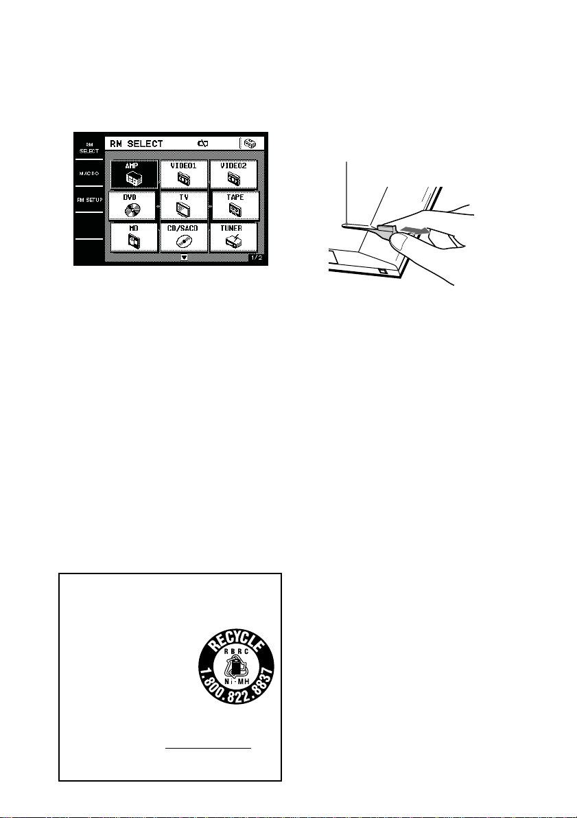
Using the touch pen
The commander’s panel is touch sensitive and
can be operated simply by touching it.
Remove the touch pen.
When returning the touch pen, always slide it
in tip first.
Touch pen holder
Remove by
sliding out.
Caution
Use only the touch pen provided with this unit or the
soft tip of your finger to operate the touch panel.
Using a commercially available writing utensil may
damage the panel and make correct operation
impossible. If the tip of the touch pen is damaged, or
the touch pen is lost, please consult your nearest Sony
dealer.
RECYCLING NICKEL METAL HYDRIDE
BATTERIES
(For customers in the United States and
Canada)
Nickel Metal Hydride batteries
are recyclable.
You can help preserve our
environment by returning your
used rechargeable batteries to
the collection and recycling
location nearest to you.
For more information regarding recycling of
rechargeable batteries, call toll free
1-800-822-8837, or visit http://www.rbrc.org/
Caution: Do not handle damaged or leaking Nickel
Metal Hydride batteries.
GB
6
Page 7

Screen hierarchy
The following diagram shows the basic composition of this unit’s screen hierarchy.
RM SELECT screen
Appears when RM SELECT is touched.
When you select the remote (component), the component operation screen appears.
MACRO screen
Appears when MACRO is touched. This screen is for performing several commands in
sequence automatically (page 23).
Preparations
RM SETUP screen
Appears when RM SETUP is touched. This screen is for setting up the operation environment
(page 30).
GB
7
Page 8
Location of Parts and Controls
This chapter provides information on the
location of buttons and how to use them to
perform basic operations.
However, some functions explained in this
section may not operate depending on the
component you are controlling.
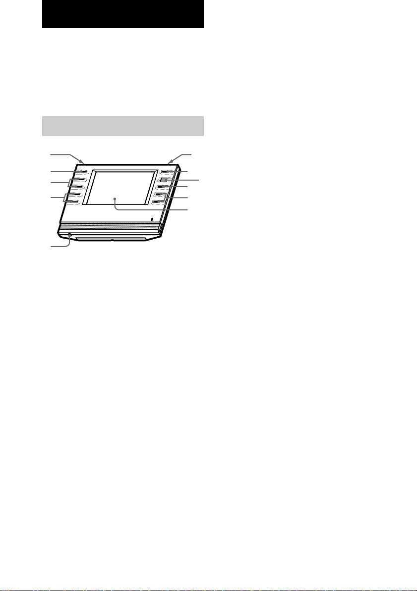
Front panel
qa
0
9
8
7
1 BACK LIGHT button
Press to turn the backlight on or off. Hold
down for about 2 seconds to turn the LCD
off. When the LCD is off, press to turn on
the LCD and backlight.
• To prolong use of the battery, the LCD
automatically turns off if there is no command
entered in the touch panel for 60 seconds.
• To view the LCD display without turning on the
backlight, touch the touch panel when both the
backlight and LCD are off.
2 ?/1/SYSTEM STANDBY button*
Normally used to turn the amplifier/receiver
on or off. When the amplifier/receiver in the
2nd or 3rd zone is on use, only the main
receiver turns on or off.
When pressed for more than 2 seconds, it
turns off all Sony components (SYSTEM
STANDBY) by executing the Macro Play
function SYSTEM OFF program (page 23),
even when the amplifier/receiver in the 2nd
or 3rd zone is on use.
2
4
5
6
1
3 Jog dial
Rotate to scroll through items in a list (etc.).
Push to select the highlighted item.
4 MUTING button*
Use to mute the sound of the amplifier/
receiver.
5 MASTER VOL +/– buttons*
Use to adjust the volume of the amplifier/
receiver.
6 Touch panel
Touch to operate. The commander turns on
automatically.
7 Stereo mini jack
3
Use to upgrade the firmware in the future.
8 TV VOL +/– buttons*
Use to adjust the volume of the TV.
9 TV CH +/– buttons*
Use to select the channel of the TV.
0 TV INPUT button*
Use to select the input of the TV.
qa SLEEP button*
Use to operate the amplifier/receiver’s sleep
timer function. The sleep timer settings
appear in the amplifier/receiver’s display,
not the commander’s LCD.
* The commander emits the remote code for
operating the AMP (amplifier/receiver) or TV that
is registered to this commander using the IR
SETUP function (page 10).
If you register two or more AMPs or TVs, the
commander emits the remote code for the
component (icon) that appears first (on the left top
side) in the RM SELECT screen.
GB
8
Page 9

Rear panel
1
23
1 Touch pen
2 Touch pen holder
Keep the touch pen here when not in use.
3 Transmitter/receiver section
Remote code receiver section
Transmits and receives infrared signals to
and from the component.
When using the Learning function, this
section receives the remote codes from
other remote controls.
To reset the commander
Normally, you never have to reset the
commander. However, if the commander does
not respond when you press the buttons or
touch the screen, do the following to reset the
commander. You will not lose any Macro
function settings or commands programmed
with the Learning function.
Carefully press the reset button on the
back of the commander with a paperclip or
a pen.
Location of Parts and Controls
GB
9
Page 10

Basic Operations
Registering the
components
The following procedure lets you set up the
commander to operate the components.
RM SELECT screen setup
(HOOK UP)
You can set the RM SELECT screen not to
display the remotes (components) you do not
use.
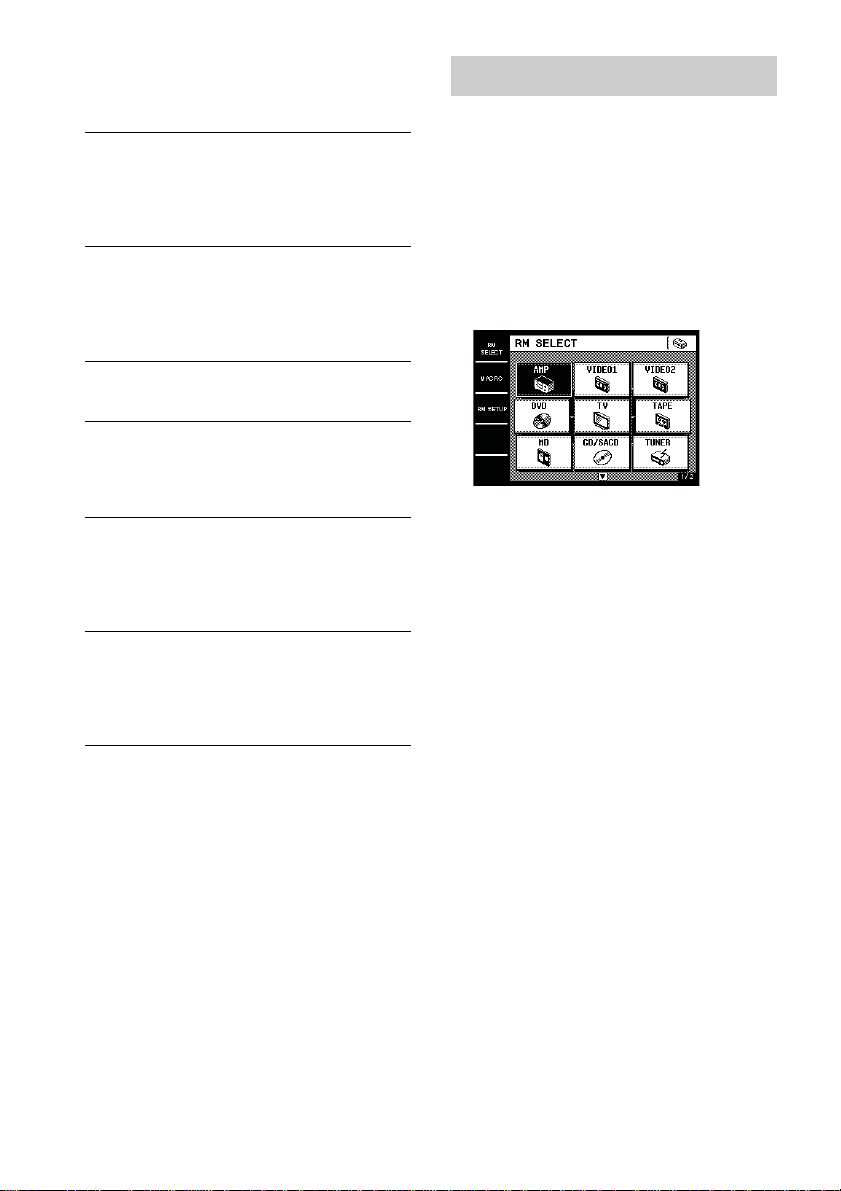
1 Touch RM SELECT.
The RM SELECT screen appears.
RM SELECT
Touch here to display the
pull-down menu.
4 Select the component not to be
displayed and touch NO.
To display other items, use the jog dial, or
touch v or V to scroll through the list.
To display the components in the RM
SELECT screen
Touch YES instead of NO in step 4.
Tip
Components that have been registered (see below) are
set to “YES” automatically.
Registering the components
(IR SETUP)
1 Touch RM SELECT.
The RM SELECT screen appears.
2 Touch the remote (component) you
want to register (“VIDEO1” for
example).
Or, turn the jog dial to select the remote
(component), then press the jog dial to enter
the selection. The screen for operating the
component appears.
To display other items, use the jog dial, or
touch v or V to scroll through the list.
2 Touch .
The pull-down menu appears.
3 Touch HOOK UP in the pull-down
menu.
The HOOK UP screen appears.
GB
10
Pull-down menu
3 Touch .
The pull-down menu appears.
Page 11

4 Touch IR SETUP in the pull-down
menu.
The IR SETUP: CATEGORY screen
appears.
5 Select the component category (“VCR”
for example).
To display other items, use the jog dial, or
touch v or V to scroll through the list. The
IR SETUP: MAKER CODE screen appears.
6 Select the maker and the command
mode for the component (“Sony VTR1”
for example).
See “Maker compatibility list” on page 37.
The component selected in steps 5 and 6
will be registered at the remote (component)
selected in step 2, and the screen for the
selected category appears. The IR setting is
displayed at the bottom of the screen.
A long beep sound is emitted to indicate
that registration was successful. Operation
is now possible from the RM SELECT
screen.
To stop registration at any time
Touch EXIT or CANCEL during any step.
Notes
• Depending on the maker, certain remote codes may
not exist and cannot be operated with the keys
(icons) on the screen. These keys are dimmed.
• When registering components made by certain
manufacturers, some commands may not function
even though they are displayed.
• Depending on the model or the model year, you
cannot operate the component even it is listed in the
“Maker compatibility list”. In this case, you can use
the Learning function to program the commands of
the remote supplied with the component (page 26).
• To operate the amplifier in the 2nd room, select
“AMP” in the IR SETUP: CATEGORY screen and
select “Sony MULTI ROOM1” in the IR SETUP:
MAKER CODE screen. This is initially registered
in the RM SELECT screen (2/2) as “2ND ZONE”.
• To operate the amplifier in the 3rd room, select
“AMP” in the IR SETUP: CATEGORY screen and
select “Sony MULTI ROOM2” in the IR SETUP:
MAKER CODE screen. This is initially registered
in the RM SELECT screen (2/2) as “3RD ZONE”.
The following tables explain the component
categories for Sony amplifier/receiver (AMP)
and tuner (TUNER).
AMP
Sony AV
SYSTEM 1
Sony AV
SYSTEM 2
Sony AV
SYSTEM 3
Sony AMP
Sony AV
PRE AMP
Sony AV
MASTER
Sony MULTI
ROOM1
Sony MULTI
ROOM2
Select this when the command mode
of the amplifier/receiver is AV1 (AV
SYSTEM1).
Select this when the command mode
of the amplifier/receiver is AV2 (AV
SYSTEM2).
(Default setting of AMP in the RM
SELECT screen.)
Select this when the amplifier/receiver
operates under AV SYSTEM3. (Home
theater system, etc.)
Select this when you use the Sony
pure amplifier.
Select this when you use the Sony
pre amplifier. (TA-E9000ES, etc.)
Select this when you use the former
Sony AV amplifier.
Select this when you use the 2nd
zone function of the AV amplifier/
receiver.
(Initially registered in the RM
SELECT screen (2/2).)
Select this when you use the 3rd
zone function of the AV amplifier/
receiver.
(Initially registered in the RM
SELECT screen (2/2).)
continued
Basic Operations
GB
11
Page 12
Registering the components
(continued)
TUNER
Sony TUNER
(AU1)
Sony TUNER
(AU2)
Sony TUNER
(SYS1)
Sony TUNER
(SYS2)
Sony TUNER
(MLT1)
Sony TUNER
(MLT2)
Select this when the command mode
of the amplifier/receiver is AV1 (AV
SYSTEM1).
Also, select this when the tuner does
not operate under Sony TUNER
(SYS1).
Select this when the command mode
of the amplifier/receiver is AV2 (AV
SYSTEM2).
Also, select this when the tuner does
not operate under Sony TUNER
(SYS2).
Select this when the command mode
of the amplifier/receiver is AV1 (AV
SYSTEM1).
Select this when the command mode
of the amplifier/receiver is AV2 (AV
SYSTEM2).
(Default setting of TUNER in the
RM SELECT screen.)
Select this when you control the
tuner in the main room from the 2nd
zone. The tuner operations you can
control depend on the receiver in the
main room. (Some receivers does
not receive this code.)
Select this when you control the
tuner in the main room from the 3rd
zone. The tuner operations you can
control depend on the receiver in the
main room. (Some receivers does
not receive this code.)
Operating the components
Selecting the remote
(component)
To operate the registered components, first
display the RM SELECT screen, then select the
remote (component) you want to operate (CD/
SACD, MD, etc.).
1 Touch RM SELECT.
The RM SELECT screen appears.
2 Touch the remote (component) you
want to operate.
Or, turn the jog dial to select the remote
(component), then press the jog dial to enter
the selection. The screen for operating the
component appears. Touch B or b to
display other screens. See the tables on
pages 12–17 for information on the
displayed keys.
To display other items, use the jog dial, or
touch v or V to scroll through the list.
Tips
• You can change the name of remotes (components)
(page 29).
• On the last screen for each remote (component),
there are 8 keys specially for use with the Learning
function (USER RESERVE KEYS). You can use
these keys for programming additional remote
codes (page 28).
12
GB
Page 13
Operation examples
Tables of preset functions
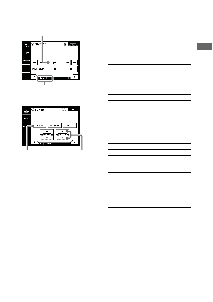
Operating a CD/SACD (CD player)
Touch to start playback.
Selected maker and category
(page 10)
Operating a tuner
Touch to select the
FM or AM band.
Touch to scan the
radio stations.
Notes
• Depending on the registered component, certain
keys (icons) may not function. These keys are
dimmed.
• These tables explain the major functions of the
keys. Depending on the registered component, the
keys may operate differently.
AMP
Key Function
POWER1)To turn the power on/off.
VIDEO 1 To select the input source: VIDEO 1
VIDEO 2 To select the input source: VIDEO 2
VIDEO 3 To select the input source: VIDEO 3
VIDEO 4 To select the input source: VIDEO 4
VIDEO 5 To select the input source: VIDEO 5
LD To select the input source: LD
DVD To select the input source: DVD
TV/SAT To select the input source: TV/SAT
TAPE To select the input source: TAPE
MD/DAT To select the input source: MD/DAT
CD/SACD To select the input source: CD/SACD
TUNER To select the input source: TUNER
PHONO To select the input source: PHONO
i.LINK To select the input source: i.LINK
2)
2CH
A.F.D. To select the decoding mode.
MOVIE To select the sound fields for movies.
MUSIC To select the sound fields for music.
DIRECT To turn off the sound field or equalizer.
SURR BACK
DECODING
NIGHT To turn on or off the NIGHT MODE
MODE function.
MULTI 1 To select “MULTI CH IN 1”.
MULTI 2 To select “MULTI CH IN 2”.
To turn off the sound field or select
2CH STEREO mode.
To select the surround back decoding
setting.
Basic Operations
continued
13
GB
Page 14

Operating the components
(continued)
Key Function
LEVEL To adjust the balance between front left
FRONT and right speakers.
BALANCE
2)
L/R
LEVEL
CENTER
2)
+/–
LEVEL SUB
WOOFER
2)
+/–
SLEEP
MUTING1)To mute the volume on the amplifier/
VOLUME To raise or lower the volume.
1)
+/–
2)
EQ
TEST
TONE
ON To activate the on-screen display.
SCREEN
MAIN
MENU
v/V/b/B2)To select a menu item.
ENTER2)To enter the selection.
DISPLAY2)To select the displayed information.
DIMMER2)To adjust the brightness of the display.
+12V To turn on or off the 12V TRIGGER
TRIGGER function.
OFF/ON
INPUT </>2)To select the audio input.
INPUT To select the input mode for your
MODE
To adjust the level of the center
speaker.
To adjust the level of the sub woofer.
2)
To activate the sleep timer.
receiver. Press again to cancel the
muting function.
To turn the equalizer on/off.
To output the test tone.
2)
2)
To select the menu.
2
2)
digital components.
VIDEO
Key Function
POWER To turn the power on/off.
Z To eject the video tape.
, To rewind at high speed.
INPUT To change the input mode of the VCR.
SELECT
X2 To play in the double speed.
CH +/– To select a channel.
. To proceed to the previous location.
m To rewind.
N To play.
M To fast-forward.
> To proceed to the next location.
z To record.
x To stop.
X To pause.
DISPLAY To select information displayed on the
TV screen.
ANT To switch the antenna output.
TV/VTR
SP/LP To select the playback speed.
1–9, 0 To select the channel.
Pressing 0 selects channel 10.
-/-- Press before selecting channel 11 or
higher. (After pressing -/--, use the
numeric buttons to select the channel,
then press ENTER.)
Or, press to select channel 11 directly.
ENTER To enter the selection.
Or, press to select channel 12 directly.
MENU To call the MENU display.
V/v/B/b To move the cursor.
ENTER To enter selections in the MENU
display.
1)
You can use the buttons on the front panel.
2)
Sony amplifier/receiver only. For details, see page
19.
For details on the controls of each key, refer to
the operating instructions supplied with the
amplifier/receiver.
GB
14
Page 15

DVD
Key Function
POWER To turn the power on/off.
AUDIO To change the sound.
ANGLE To switch angle.
SHUFFLE To select Shuffle Play.
REPEAT To select Repeat Play.
DISC SKIP To select next/previous disc.
+/–
. To proceed to the previous location or
song.
m To rewind.
N To play.
M To fast-forward.
> To proceed to the next location or song.
x To stop.
X To pause.
DISPLAY To select information displayed on the
TV screen.
SUB TITLE To switch the subtitle.
TOP MENU To call up the MENU display.
MENU To display the DVD menu.
V/v/B/b To move the cursor.
ENTER To enter a setting or to set items
selected from the screen.
PROGRAM
To select Program Play.
1–9, 0 Number buttons: To set items selected
from the screen.
CLEAR To clear the selected characters from
the screen.
SEARCH To change the search mode.
RETURN To return to the last previous screen.
TV
Key Function
POWER To turn the power on/off.
MUTING To mute the volume on the TV. Press
again to cancel muting function.
3)
INPUT
To change the input mode of the TV.
DISPLAY To select information displayed on the
TV screen.
JUMP To toggle between the previous and
current channels.
1–9, 0 To select the channel.
Pressing 0 selects channel 10.
-/-- Press before selecting channel 11 or
higher. (After pressing -/--, use the
numeric buttons to select the channel,
then press ENTER.)
ENTER To enter the selection.
Or, press to select channel 12 directly.
3)
CH +/–
VOLUME To raise or lower the volume.
3)
+/–
To select a channel.
SLEEP To activate the sleep timer.
MENU To display the menu.
V/v/B/b To move the cursor.
P in P To activate the picture-in picture
POSITION To change the position of the small
function.
picture.
4)
4)
SWAP To swap the small and large pictures.
WIDE To select the wide-picture mode.
SUB CH +/– To select preset channels for the small
3)
You can use the buttons on the front panel.
4)
Only with Sony TVs with the picture-in-picture
function.
5)
Only with Sony TVs that supports the wide-picture
picture.
4)
5)
mode.
Basic Operations
4)
continued
15
GB
Page 16

Operating the components
(continued)
TAPE
Key Function
SIDE A/B To select the tape deck : Deck A or B
. To proceed to the previous song.
m To rewind.
n To reverse.
N To play.
M To fast-forward.
> To proceed to the next song.
z To record.
x To stop.
X To pause.
MD
Key Function
POWER To turn the power on/off.
. To select the previous track.
m To rewind.
N To play.
M To fast-forward.
> To select the next track.
z To pause for recording.
x To stop.
X To pause.
CONTINUE
SHUFFLE To select Shuffle Play.
PROGRAM
REPEAT To select Repeat Play.
1–9, 0 To select the track number (0 selects
>10 To select numbers 10 and above.
DISPLAY To change the information on the
MENU/NO To select editing operation or cancel
YES To perform editing operation.
(dual cassette deck only).
To select Continuous Play.
To select Program Play.
track 10).
display.
editing.
CD/SACD
Key Function
POWER To turn the power on/off.
. To select the previous track.
m To rewind.
N To play.
M To fast-forward.
> To select the next track.
DISC SKIP
x To stop.
X To pause.
CONTINUE
SHUFFLE To play in random order.
PROGRAM
REPEAT To select repeat play mode.
1–9, 0 To select the track number (0 selects
>10 To select numbers 10 and above.
ENTER To enter the setting.
DISC To select the disc.
TRACK To select the track.
TUNER
Key Function
POWER To turn the power on/off.
FM/AM To select the FM or AM band.
FM MODE To select stereo or monaural reception
SHIFT To shift bands or preset select.
TUNING +/– To scan the radio stations.
PRESET +/– To scan the preset radio stations.
A To select the memory page A.
B To select the memory page B.
C To select the memory page C.
1–9, 0 Number buttons.
SHIFT To switch the memory page.
DIRECT Enters Direct Tuning mode.
MEMORY To store the preset stations.
To select a disc.
To select continuous play mode.
To use for program play.
track 10).
of FM stations.
16
GB
Page 17

CABLE
Key Function
POWER To turn the power on/off.
1–9, 0, To change the channel. For example, to
ENTER change to channel 5, press 0 and 5 (or,
JUMP To toggle between the previous and
CH +/– To select a channel.
SATELLITE
Key Function
POWER To turn the power on/off.
1–9, 0 To select the channel.
-/-- Press before selecting channel 11 or
ENTER To enter the selection.
JUMP To toggle between the previous and
CH/PAGE +/– To select the channel or the menu page.
FAVORITE To display the Favorite Station Guides.
CATEGORY
GUIDE To display the SAT guide.
INDEX To bring up the Station Index
TV/SAT To switch the output of the SAT
DISPLAY To select information displayed on the
v/V/b/B To move the cursor.
+ To enter the setting.
MENU To call up the MENU display.
EXIT To exit the mode.
press 5 and ENTER).
current channels.
Pressing 0 selects channel 10.
higher. (After pressing -/--, use the
numeric buttons to select the channel,
then press ENTER.)
Or, press to select channel 11 directly.
Or, press to select channel 12 directly.
current channels.
To display the Guide Category list.
receiver to the TV (When you connect
a TV cable or antenna to the amplifier/
receiver, the output switches between a
TV and SAT program).
TV screen.
PROJECTOR
Key Function
POWER ON To turn the power on.
POWER To turn the power off.
OFF
INPUT To switch to the input from
SELECT VIDEO jacks.
VIDEO
INPUT To switch to the input from VIDEO IN
SELECT or S VIDEO IN jacks.
SELECT
INPUT To switch to the input from INPUT A
SELECT or INPUT B jacks.
A/B
MEMORY To store the adjusted data in memory.
MENU To call up the MENU display.
v/V/b/B To move the cursor.
ENTER To enter the setting.
ZOOM +/– To adjust the zoom of the picture.
SHIFT +/– To adjust the lens shift of the picture.
FOCUS +/– To adjust the focus of the picture.
BRIGHT +/– To adjust the brightness.
CONTRAST To adjust the contrast.
+/–
continued
Basic Operations
17
GB
Page 18

Operating the components
(continued)
LD
Key Function
POWER To turn the power on/off.
SIDE A/B To select disc side A or B.
. To proceed to the previous location or
m To rewind.
N To play.
M To fast-forward.
> To proceed to the next location or song.
x To stop.
X To pause.
DISPLAY To select information displayed on the
PROGRAM
REPEAT To repeat current track or programmed
1–9, 0 To select the track number (0 selects
+10 To select numbers 10 and above.
SEARCH To change the search mode.
FRAME/ To change the frame or time
TIME information.
song.
TV screen.
To program the tracks.
tracks.
track 10).
VIDEO CD
Key Function
POWER To turn the power on/off.
INDEX To return to the previous menu.
PREVIOUS
INDEX To go to the next menu.
NEXT
. To proceed to the previous location or
song.
m To rewind.
N To play.
M To fast-forward.
> To proceed to the next location or song.
x To stop.
X To pause.
1–9, 0 To select the track number (0 selects
track 10).
>10 To select numbers 10 and above.
RETURN To return to the last previous screen.
TIME To change the time information.
SELECT To select the menu.
DAT
Key Function
POWER To turn the power on/off.
. To select the previous track.
m To rewind.
N To play.
M To fast-forward.
> To select the next track.
z To record.
x To stop.
X To pause.
REPEAT To select Repeat Play.
1–9, 0 To select the track number (0 selects
track 10).
CLEAR To clear the setting.
ENTER To enter the setting.
18
LIGHT
Key Function
SCENE 1–16 To select the scene.
OFF To turn off the power.
BRIGHT To adjust the brightness.
+/–
GB
Page 19

Operations for Sony Amplifiers/Receivers
When using Sony amplifiers/receivers, you can
operate various functions. Before operating,
register the Sony amplifier/receiver (page 10).
When selecting Sony amplifier/receiver from
the IR SETUP: MAKER CODE list, be sure to
select the appropriate command mode.
About the command mode (IR type)
If the amplifier/receiver’s command mode (IR type)
and the commander’s command mode (IR type) do
not match, you cannot use the commander to operate
the amplifier/receiver.
Tip
To use the multi room function of the amplifier/
receiver, select SONY MULTI ROOM1 (or 2) from
the IR SETUP: MAKER CODE list. The multi room
functions (2ND ZONE and 3RD ZONE) are initially
registered in the RM SELECT screen (2/2).
Operating the amplifier/
receiver
1 Touch RM SELECT.
The RM SELECT screen appears.
2 Touch AMP.
The screen for operating the amplifier/
receiver appears.
3 Touch B or b to select the screen.
For details on each screen, see below.
Notes
• Depending on the amplifier/receiver, some
commands may not function.
• For details about the operations, refer to the
operating instructions supplied with the amplifier/
receiver.
Screen 2/6
This screen is mainly for enjoying surround
sound.
Operations for Sony Amplifiers/Receivers / 2 Way Remote Operations
Screen 3/6
This screen is for adjusting the level and
balance and adjusting the volume.
Screen 4/6
This screen is mainly for adjusting the
equalizer and outputting the test tone. You can
also adjust various settings using the MAIN
MENU key, cursor keys, and ENTER key.
When the amplifier/receiver has ON SCREEN
function, it is recommended to adjust the
settings using the TV screen.
Screen 1/6
This screen is mainly for switching the input.
Screen 5/6
This screen is mainly for setting the display on
the amplifier/receiver and selecting the audio
input.
19
GB
Page 20

2 Way Remote Operations
Understanding the 2 way remote
system
This commander operates under a 2 way
remote system. With the 2 way remote system,
the component responds to signals sent from
the commander by sending additional signals
(information about the status of the component,
text data, etc.) back to the commander. Thus,
operations are performed as a result of
communication between the commander and
the component.
Operation example
When a 2 way component is connected to the
amplifier/receiver with a Control A1/A1
MD deck
CD player
Control A1/A1
cord
cord
Commander
Component
When using a home entertainment system
comprised of several components compatible
with the 2 way remote system, please restrict 2
way remote system operation to a single
component. Generally, the 2 way remote
system is turned off on all components except
for the amplifier/receiver.
If you would like to turn off the amplifier/
receiver’s 2 way remote system, refer to
“Setting up the 2 way remote” in the operating
instructions supplied with the amplifier/
receiver.
Amplifier/
Receiver
When operating the 2 way CD changer directly
CD changer
Notes for the 2 way remote operation
• To ensure good communication conditions, carry
out the 2 way remote operation from directly in
front of, and close to the component.
1m – 2m
• Do not move the component during the 2 way
remote operation.
• The commander receives and displays data
transmitted from the component. Communication
errors may occur if the commander’s transmitter/
receiver section is not directed properly toward the
component’s IR receptor. Be sure to point the
commander’s transmitter/receiver section towards
the component’s IR receptor.
Commander
Commander
20
GB
Page 21

Operating the amplifier/
receiver
You can operate a Sony 2 way amplifier/
receiver. You can also download the names of
components (inputs). Before operating, register
the Sony amplifier/receiver using the IR
SETUP function (page 10).
When performing the following procedure,
be sure to turn on the amplifier/receiver
and point the commander towards the IR
receptor on the amplifier/receiver.
To operate the amplifier/
receiver
1 Select the Sony amplifier/receiver in the
RM SELECT screen.
“1WAY 2WAY” appears.
Operations for Sony Amplifiers/Receivers / 2 Way Remote Operations
To register a 2 way amplifier/
receiver
Use the RM SETUP screen.
Note
You cannot register the amplifier/receiver if it is not
set to use the 2 way remote system. Refer to “Setting
up the 2 way remote” in the operating instructions
supplied with the amplifier/receiver.
1 Touch RM SETUP.
2 Touch AMP REGIST.
3 Touch START.
The communication starts and the amplifier/
receiver is registered to the commander.
The registered amplifier/receiver name
appears in the screen. The amplifier/receiver
name also appears in the RM SETUP screen
as the current setting.
Note
If the amplifier/receiver name appears as “model
others”, the amplifier/receiver is not registered
correctly. In this case, some 2 way operations may
not be possible.
Tip
When you can select several Sony amplifiers/
receivers in the RM SELECT screen, touch the
AMP icon that appears first.
2 Touch 2WAY.
The screen for the 2 way operation appears
and you can operate the amplifier/receiver
registered in the RM SETUP screen.
To download the names of components
(inputs), touch INPUT SELECT, then touch
INPUT NAME DOWNLOAD.
To download the names of sound fields,
touch SOUND FIELD, then touch S.F.
NAME DOWNLOAD.
Notes
•2 way operations may not be possible immediately
after turning on the amplifier/receiver.
• You cannot use the jog dial when using the 2WAY
screen.
• You cannot use the Learning function for the keys
in the 2WAY screen.
21
GB
Page 22

Operating the tuner
You can operate the built-in tuner of 2 way
receiver. You can also download the station
names registered on the receiver. Before
operating, register Sony tuner using the IR
SETUP function (page 10).
1 Switch the input to “TUNER” on the
receiver.
If AMP LINK function (page 29) is set, the
input of the receiver automatically switches
to “TUNER” when you select the tuner in
step 2.
2 Select the tuner in the RM SELECT
screen.
The communication starts.
3 To download the station names, touch
b to select the following screen (screen
4/4), then touch DOWNLOAD.
The commander starts to download the data.
Select the CD/SACD (CD player) or MD
deck in the RM SELECT screen.
The communication starts, and the information
such as disc titles and song names are
displayed.
Disc title
RELOAD
Tip
When the song number or song title is not displayed
correctly, touch RELOAD.
Song title
Touch here to scroll
the long titles
To download the data from
CD changer
You can download the data from CD changer.
1 Select CD/SACD (CD player) in the RM
SELECT screen.
2 Touch b to select the following screen
(screen 4/4), then touch DOWNLOAD.
The commander starts to download the data.
Operating the CD player or
MD deck
You can download the information (disc titles,
etc.) from Sony 2 way CD player* or MD deck.
Before operating, register Sony CD player or
MD deck using the IR SETUP function (page
10).
* Compatible with Sony CD changers (5/50/200/300/
400 CD).
GB
22
NUMBER/TITLE
Tip
You can change the order of the disc list. Touch
NUMBER to sort by the disc number, or touch
TITLE to sort by the disc names.
DOWNLOAD
Page 23

Advanced Operations
Performing several
commands in sequence
automatically (Macro Play)
The Macro Play function lets you link several
IR codes in sequential order as a single
command. The commander provides 16 macro
lists. You can specify up to 24 IR codes for
each macro list.
Tips
• MACRO 1 has been factory set to turn on Sony AV
components.
• MACRO 16 has been factory set, but you can freely
use the MACRO 16 by programming the commands
you want over the existing program.
• SYSTEM OFF has been factory set to turn off all
Sony AV components. The same program is also
executed when the ?/1/SYSTEM STANDBY
button on the front panel is pressed more than 2
seconds.
Setting the sequence of IR
codes
1 Touch MACRO.
The MACRO screen appears.
3 Touch .
The pull-down menu appears.
4 Touch MACRO SETUP in the pull-down
menu.
The macro step number (BOX) list appears.
5 Touch the macro step number for the
command you want to register (“1” for
example).
The CATEGORY list appears.
Advanced Operations
2 Turn the jog dial so that the Macro Play
number you want to program
(“MACRO3” for example) comes to the
middle box.
6 Select the category (“VCR” for
example).
The MAKER list appears.
continued
23
GB
Page 24

Performing several commands in sequence
automatically (Macro Play) (continued)
7 Select the maker (“Sony VTR1” for
example).
The COMMAND list appears.
8 Select the command (“POWER” for
example).
The items selected in steps 6 to 8 are
registered in the box selected in step 5.
The macro step number (BOX) list
reappears. You can program up to 24 steps.
To cancel programming
Touch EXIT or CANCEL during any step.
To clear the programmed IR code
Select the macro step number (BOX) you want
to clear the IR code, then select “MACRO
CLEAR” from the CATEGORY list.
To change the name of the Macro
Play
In step 4, touch MACRO NAME EDIT. Touch
the name input buttons to enter the name (up to
10 characters), then touch SET. Touch EXIT to
return to the MACRO screen.
Current name display
Name input display
Name input buttons
To start Macro Play
To operate Sony components
When selecting the category in step 6, you can
select the operation such as turning on/off Sony
components or switching the input of Sony TVs.
To delay the output of an IR code
Select “WAIT TIME” from the CATEGORY
list. The wait time list (“1sec” to “60sec” (1 to
60 seconds)) appears. Select the time you want
to wait.
To use learned codes under the
Macro Play function
Select “RESERVE KEYS” from the
CATEGORY list. Then, select the button for
the learned IR code.
GB
24
1 Touch MACRO.
The MACRO screen appears.
2 Turn the jog dial to select the Macro
Play, then press the jog dial to enter the
selection.
To cancel the Macro Play during operation,
press the jog dial again.
Note
If the Macro Play function does not work properly,
try setting a “WAIT TIME” between each command.
Page 25

To start Macro Play
automatically (MACRO LINK)
You can link the remote (component) to
operate the Macro Play automatically when the
remote (component) is selected.
The following procedure uses an example to
execute MACRO4 when “DVD” is selected in
the RM SELECT screen.
AUTO POWER function
When Sony components are registered and the remote
(component) is selected, this function enables you to
turn on the component automatically. Besides, when
Sony video components (VCR, DVD, etc.) are
registered and the remote (component) is selected,
this function enables you to turn on both TV and the
component, and switch the input of the TV
automatically.
1 Touch RM SELECT.
The RM SELECT screen appears.
2 Turn the jog dial to select the remote
(component) you want to link to the
Macro Play (“DVD” for example).
When you touch the remote (component),
touch B to display the RM SELECT screen.
4 Touch MACRO LINK in the pull-down
menu.
The MACRO LINK screen appears.
5 Select the Macro Play (“MACRO4” for
example) you want to link to the remote
(component).
A check (✔) appears in front of the selected
Macro Play.
6 Touch EXIT.
The RM SELECT screen reappears.
M appears in the box of the remote
(component) selected in step 2.
Advanced Operations
3 Touch .
The pull-down menu appears.
continued
25
GB
Page 26

Performing several commands in sequence
automatically (Macro Play) (continued)
Using the Auto Power function
In step 5, link the remote (component) to
“AUTO POWER”. For the video components,
the following display appears. Select the wait
time and the input of the TV.
Select the wait time.
Select the input of the TV.
Notes
• The TV input may not switch automatically on all
Sony TVs. This is because some TVs cannot
receive remote control codes immediately after
being turned on. In this case, set the wait time.
• When you select “TV” as the video input, the TV
input does not switch.
To cancel MACRO LINK
Select “OFF” in the MACRO LINK screen.
Learning the commands of
other remote commanders
Setting remote control codes
that are not stored in the
commander
When a remote control code is not one of the
presets stored in the commander, it is possible
for the commander to learn the code using the
Learning function.
Learning function can be used for each preset
operation keys and USER RESERVE KEYS.
To program an IR code to the preset
operation keys
1 Touch RM SELECT.
The RM SELECT screen appears.
2 Touch the remote (component) (“MD”
for example).
Or, turn the jog dial to select the remote
(component), then press the jog dial to enter
the selection. The screen for operating the
component appears.
3 Touch .
The pull-down menu appears.
26
4 Touch LEARN in the pull-down menu.
The commander enters the learning mode.
“LEARN” appears.
GB
Page 27

5 Point the remote code receiver section
of this commander toward the receiver/
transmitter on the remote control to be
learned.
8 Touch .
About 5 cm – 15 cm
6 Touch the key on this commander you
want to use the Learning function
(“N” for example).
A mark (s) blinks in the bottom right
corner of the key. Perform step 7 within 30
seconds after the mark starts blinking.
7 Press the appropriate button on the
remote control to send the remote
control code.
Press the button more than 1 second. When
this commander receives the remote control
code and the learning is successful, the
mark (s) in the bottom right corner stops
blinking, and another mark (x) appears in
the upper right corner of the key.
9 Touch USE in the pull-down menu.
The commander returns to the operation
mode.
To use the Learning function for the
buttons on the front panel
Use the Learning function for the same named
keys in the operation screen for AMP or TV.
Example: When you use the Learning function
for the MUTING key in the operation screen
for AMP, the MUTING button on the front
panel is also registered with the same code.
To clear the learned code
Perform steps 1 to 4 above, and touch the key
you want to clear the learned code. The
following display appears. Touch CLEAR to
clear the learned code.
To overwrite the learned code
Perform steps 1 to 5 above, and touch the key
you want to overwrite the learned code. The
same display as “To clear the learned code”
appears. Touch OVER WRITE. A mark (s)
blinks in the bottom right corner of the key.
Then follow steps 7 to 9.
Advanced Operations
continued
27
GB
Page 28

Learning the commands of other
remote commanders (continued)
To program the IR code to the USER
RESERVE KEYS
1 Perform steps 1 to 5 of “To program an
IR code to the preset operation keys”
(page 26), then in step 6, select one of
the USER RESERVE KEYS you want to
program the IR code.
The LEARN screen appears.
Selected key
Name input buttons
Message window
Command key
2 Touch LEARN.
“Please Send Signal.” appears. Perform step
3 within 30 seconds after the mark starts
blinking.
3 Press the appropriate button on the
remote control to send the remote
control code.
Press the button more than 1 second. When
this commander receives the remote control
code and the learning is successful, “This
key has a code.” appears, and a mark (x)
appears in the upper right corner of the key.
4 Touch EXIT.
5 Touch .
6 Touch USE in the pull-down menu.
The commander returns to the operation
mode.
To cancel learning
Touch CANCEL in step 2.
To clear the learned code
After step 3, touch CLEAR. “Clear?” appears.
Then, touch “YES”. The learned code is
cleared.
Tip
• You can test the USER RESERVE KEYS. Touch
“TEST” after “This key have code.” appears in step
3. The learned code is sent from the commander,
and if correct, the corresponding operation is
performed.
• You can make a name of up to 14 characters for the
USER RESERVE KEYS. Touch the name input
buttons as displayed to enter the name.
• To ensure the proper learning, we recommend using
new batteries in the remote to be learned.
Notes
• Normally, each remote (component) has 8 USER
RESERVE KEYS. However, depending on the
signals of the codes being learned, it may not be
possible for the commander to store codes for all
USER RESERVE KEYS.
• Some remote control codes cannot be learned.
Using a command that has
been learned
Select the key which has learned the command.
28
GB
Page 29

Switching the input on the
amplifier/receiver
automatically (AMP LINK)
You can set the commander to switch the input
on the amplifier/receiver to the component
selected in the RM SELECT screen
automatically.
The following procedure uses an example to
switch the input on the amplifier/receiver to
CD when “CD/SACD” is selected in the RM
SELECT screen.
1 Touch RM SELECT.
The RM SELECT screen appears.
2 Turn the jog dial to select the remote
(component) you want to use with the
AMP LINK function (“CD/SACD” for
example).
When you touch the remote (component),
touch B to display the RM SELECT screen.
5 Select the function you want to switch
the function to (“CD/SACD” for
example).
A check (✔) appears in front of the selected
function.
Advanced Operations
6 Touch EXIT.
The RM SELECT screen reappears.
A appears in the box of the remote
(component) selected in step 2.
To cancel AMP LINK
Select “OFF” in the AMP LINK screen.
3 Touch .
The pull-down menu appears.
4 Touch AMP LINK in the pull-down
menu.
The AMP LINK screen appears.
Changing the name of the
remote (component)
You can change the name of the remote
(component) that appears in the RM SELECT
screen (up to 10 characters).
1 Touch RM SELECT.
The RM SELECT screen appears.
continued
29
GB
Page 30

Changing the name of the remote
(component) (continued)
2 Touch the remote (component) you
want to change the name (“VIDEO1” for
example).
Or, turn the jog dial to select the remote
(component), then press the jog dial to enter
the selection. The screen for operating the
component appears.
3 Touch .
The pull down menu appears.
Adjusting the
commander’s operating
environment
The RM SETUP screen allow you to adjust
various settings and customize the
commander’s operating environment.
1 Touch RM SETUP.
The RM SETUP screen appears.
Current setting
2 Touch the menu you want to adjust.
See below for details about each menu.
3 Touch EXIT to return to the RM SETUP
screen.
4 Touch NAME EDIT in the pull-down
menu.
The RM NAME EDIT screen appears.
Current name display
Name input display
Name input buttons
5 Enter the name you want.
6 Touch SET.
The new name is set in the commander.
7 Touch EXIT.
GB
30
x Adjusting the contrast of the display
(CONTRAST)
You can adjust the contrast of the display.
Touch + or – to adjust the contrast.
Tips
• Depending on the brightness of the room and the
angle at which the commander is viewed, the LCD
may be difficult to see. When this occurs, changing
the angle of the commander or adjusting the
contrast of the LCD may make the LCD easier to
see. When fingerprints (etc.) get on the LCD, wipe
the LCD with a soft, dry cloth. It is recommended
to use the touch pen supplied with the commander.
• The contrast lightens a little when the temperature
lowers, and darkens a little when the temperature
rises.
Page 31

x Selecting the icon size (ICON SIZE)
You can select the icon size of the RM
SELECT screen. Touch SMALL to use small
icons (12 icons are displayed at a time) or
touch LARGE to use large icons (9 icons are
displayed at a time).
x Setting the LCD turn off time
(LCDOFFTIME)
The turn off time can be set between 10 and 90
seconds in 1 second intervals. Touch + or – to
adjust the turn off time.
Tip
The turn off time is factory set to 60 seconds. To
preserve battery life, set to a shorter time.
x Adjusting the position of the touch
panel (TOUCHPANEL)
Adjust the position of the LCD when it shifts
from the normal operating position.
Touch the center of each of the 4 dots.
“Adjusted” appears in a short while and long
beep is emitted.
x Setting the warning alarm and the
operating beep sound (ALARM/BEEP)
You can set the warning alarm and the
operating beep sound on or off. Touch ON to
output the sound. Touch OFF to turn off the
sound.
x Returning settings to their factory
preset settings (ALL CLEAR)
Touch YES to erase all memorized settings and
return them to their factory presets. A long
beep is emitted and all settings return to the
factory settings.
Please note that once erased, settings cannot be
returned.
x Registering the 2 way amplifier/receiver
(AMP REGIST)*
When using Sony 2 way amplifier/receiver,
touch START to download the amplifier/
receiver information. For details, see page 21.
x Setting the backlight (BACK LIGHT)
You can choose to turn the backlight on
manually or to have the commander remember
your previous setting.
Set to ONCE (factory setting) if you prefer to
turn the backlight on manually as needed. Set
to KEEP if you want the commander to
remember the previous backlight setting. For
example, if the backlight was on the last time
the LCD was on, the backlight will
automatically come on again the next time the
LCD comes on. Likewise, if the backlight was
off, it will stay off the next time too.
* When carrying out this operation, make sure that
the amplifier/receiver’s power is on, and be sure to
point the commander’s transmitter/receiver section
toward the display on the amplifier/receiver. Also,
operate the commander at a distance of about 1–2
meters from the amplifier/receiver.
Advanced Operations
31
GB
Page 32

Additional Information
Safety regulations
On safety of the main unit
(For the customers in Europe)
• Do not use an AC adapter other than that
provided with the unit. Otherwise, a fire or
electric shock may result.
• Do not use the unit for an extended period of
time. Extended use of the unit may cause aches
and pains in your arms and wrists. Whenever
you feel an ache in a part of your body during
the use of the unit, immediately stop using it
and take a rest. Should the aches and pains
persist after the rest, please consult your doctor.
• Do not install the unit where it will be exposed
to oil soot, steam, moisture and excessive dust.
Installing the unit in such a place as described
above may result in a malfunction. Also note
that using the unit in an environment other than
the operating environment specified in the
operating instructions may lead to malfunction.
• Do not allow water or a foreign object to enter
the inside of the unit. Penetration of water or a
foreign object may lead to malfunction.
• Do not attempt to disassemble the unit. The unit
contains high-voltage parts inside. Careless
opening of the case or front cover or
modification of the unit may lead to
malfunction. Refer internal check and servicing
to your nearest Sony dealer.
• Do not touch the AC adapter with a wet hand. If
you plug or unplug the AC adapter with a wet
hand, electric shock may result.
• Do not wrap the AC adapter cord around the
AC adapter body. Otherwise, wire
disconnection or malfunction may result.
• Do not cover the main unit and/or AC adapter
with a cloth or cushion. Otherwise, heat buildup may cause deformation of the case or a fire
hazard.
• Install the unit on a stable surface. Do not
install the unit on an unstable bench or tilted
surface. Also do not install it sideways or
upside down. Otherwise, the unit may fall or
topple down, causing human injuries.
• Do not place a heavy object on the unit.
Otherwise, damage to the unit or an injury to a
person may result.
• Unplug the AC adapter before maintenance.
Otherwise, malfunction may result.
• Unplug the AC adapter when the unit is not to
be used for an extended period. When you will
not use the unit for an extended period, unplug
the AC adapter from the power outlet for safety.
• Do not install or store the unit in a place
exposed to direct sunlight or near a heater.
Otherwise, the internal heat build-up may cause
malfunction.
• Do not apply shock or impact to the LCD. The
screen (display panel) is made of glass. It may
crack and cause injuries if it is twisted or
dropped, if you rest your elbow on it or a heavy
object is placed on it.
• Be careful not to touch or hit the LCD with a
hard object. Otherwise, the LCD may break,
causing malfunction or human injury.
• Do not apply a strong shock or impact to the
main unit. Otherwise, malfunction may result.
• When thunder begins, do not touch the AC
adapter. Otherwise, there is a risk of electric
shock.
• Do not place the AC adapter near water. Water
on the inside or the outside of the adapter, or
use in a bathroom may result in fire or electric
shock hazard.
32
GB
Page 33

On the safety of rechargeable
battery
• Do not remove the battery cover. Removing the
screws will expose dangerous high-voltage
parts inside the battery. Refer servicing to your
nearest Sony dealer.
• Use only the supplied battery charger to
recharge the battery. If it is recharged with a
different charger or under different conditions,
the following may result; recharging at an
excessive current level, fluid leaks, heat
generation, cracking, or fire ignition of the
battery.
• Do not throw the unit in fire or heat it.
Otherwise, fluid leaks, cracking, or fire ignition
of the battery may occur due to melting of the
insulating materials of the inner cells, damage
to the safety valves and mechanisms, or ignition
of the produced hydrogen.
• If recharging does not complete in the specified
time, stop recharging the battery. If recharging
is continued in such a case, excessive
recharging may cause fluid leak or heat
generation from the battery.
• Do not use the unit which is discolored,
deformed or otherwise altered. Otherwise, heat
generation, cracking, or fire ignition of the
battery may result.
• The rechargeable battery contains alkaline fluid
inside, and contact of the battery fluid with
human skin or clothes may damage the skin.
Should an accedental contact occur,
immediately wash the skin or clothes with clean
water including tap water. Also, penetration of
the battery fluid may cause loss of eyesight.
Should this happen, immediately rise the eye
with clean water such as tap water and consult
your doctor.
• Do not immerse the unit in either fresh or sea
water or moisten it with water. This may cause
heat generation from the battery as well as
corrosion of the battery terminals.
• The ambient temperatures during the battery
recharging should be as specified below. If
recharging is performed outside the specified
temperature range, fluid leak or heat generation
from the battery may occur as well as drop in
the performance and service life of the battery.
Recharging: 5 °C to 35 °C
• Do not use or leave the unit under direct strong
sunlight, in a closed automobile under the sun
or near a heater. Otherwise, fluid leak or heat
generation from the battery may occur as well
as drop in the performance and service life of
the battery.
• If you notice the unit generating very high heat
or some other abnormality during the first use
of the unit after purchase, do not use it but bring
or forward it to your dealer.
• When the unit is used for the first time after
purchase or when it has not been used for a
long period, the battery may not be charged
fully. Recharge the battery in such cases.
• When the unit has not been used for an
extended period, the battery may become
unable to be recharged fully or at all. To
prevent such a trouble, it is recommended to
recharge it every other month even during the
period in which it is not used.
continued
Additional Information
33
GB
Page 34

Safety regulations (continued)
Precautions
On the safety of AC adapter
and battery charger
• To prevent electric shock, fire or malfunction,
do not attempt to open or modify the units.
• To prevent electric shock, smoke generation or
fire hazard, do not use a damaged AC adapter
cord.
• Do not moisten the AC adapter and battery
charger. If a liquid such as water or a pet’s
urine enters the unit, heat generation, electric
shock or malfunction may result. Take care in
the place and method of their handling.
• Should a liquid such as water penetrate the
battery charger, immediately unplug its AC
plug from the power outlet.
• To prevent electric shock, do not touch the AC
adapter, battery charger, AC adapter cord or AC
plug with wet hands.
• Do not short-circuit the charger terminals while
the battery charger is plugged to a power outlet.
Also do not touch the charger terminals with
your hand or finger. Otherwise, a fire,
malfunction or electric shock may result.
• Never use the AC adapter or battery charger
under high humidity, for example in a
bathroom. Otherwise, electric shock may result.
• Remove dust from the AC plug, for it may
cause a fire hazard.
• To prevent an electric shock or fire hazard, do
not place a heavy object on the AC adapter.
• When unplugging the AC plug from the power
outlet, be sure to grasp the AC adapter body,
not the cord. If the cord is pulled, it may be
damaged, causing an electric shock or fire
hazard.
• Do not place the AC adapter and battery
charger on an unstable surface during
recharging. Also do not cover or wrap them
with a cloth or cushion. Otherwise, heat buildup may cause a fire hazard.
• Replace the AC adaptor with one of the same
type if replacement is necessary. Please ask the
nearby Sony dealer of a model name.
On power sources
(For customers in Europe)
The unit is not disconnected from the AC
power source (mains) as long as it is connected
to the wall outlet, even if the commander itself
has been turned off.
On the touch pen
Use only the touch pen provided with this unit
or the soft tip of your finger to operate the
touch panel. Using a commercially available
writing utensil may damage the panel and make
correct operation impossible. If the tip of the
touch pen is damaged, or the touch pen is lost,
please consult your nearest Sony dealer.
On battery life per charge
When the backlight is not necessary, do not
press BACK LIGHT to turn on the LCD.
Touch the touch panel to turn on just the LCD.
The life of the battery charge will be
prolonged. The life of the battery charge may
be shortened depending on the conditions in
which the commander is used.
On cleaning
Clean the cabinet, panel and controls with a
soft cloth slightly moistened with a mild
detergent solution. Do not use solvent such as
thinner, benzine, or alcohol as these will
damage the surface of the commander.
On nameplate
(For customers in Europe)
The nameplate is located on the bottom
exterior.
If you have any question or problem
concerning your commander, please consult
your nearest Sony dealer.
34
GB
Page 35

Troubleshooting
If you experience any of the following
difficulties while using the commander, use
this troubleshooting guide to help you remedy
the problem. Should any problem persist,
consult your nearest Sony dealer.
Operation can not be done with the commander.
• When using the commander as a 2-way remote,
check that the amplifier/receiver and components
are connected correctly (page 20).
• The commander and component are too far apart.
• Make sure that there are no objects between the
commander and component.
• Make sure that the component’s power is turned
on.
• The commander’s transmitter/receiver section is
not pointed at the component.
• The commander’s battery is exhausted. Recharge
the battery (page 5).
• There is an invertor system florescent light near
the commander or component. Please place away
from the florescent light.
• Make sure you have selected the correct remote
(component) on the commander.
• When you operate a non-Sony component, the
remote (component) may not function properly
depending on the maker and model of the
component.
When using the Sony amplifier/receiver, the
amplifier/receiver’s functions and modes do not
correlate with the displays on the commander.
• The information of the amplifier/receiver is not
downloaded. Download the information (page
21).
The LCD does not appear.
• The LCD is not turned on. Touch the touch
panel.
• Contrast is too light or too dark. Adjust the
contrast (page 30).
The LCD shifts from the normal operating
position.
• Adjusting the position of the touch panel (page
31).
When a component is connected to the
amplifier/receiver with Control A1/A1
Auto Function does not work properly.
• Download the amplifier/receiver data (page 21).
Commands of components made by
manufacturers other than Sony do not function.
• When registering components made by certain
manufacturers, some commands may not
function. These keys are dimmed.
When using 2-way Sony amplifier/receiver, the
commander and the amplifier/receiver cannot
communicate.
• If the amplifier/receiver’s command mode (IR
type) and the commander’s command mode (IR
type) do not match, transmission is not possible
between the commander and the amplifier/
receiver.
appears in the screen.
•2 way communication error occured.
• When using the commander as a 2-way remote,
check that the amplifier/receiver and components
are connected correctly (page 20).
• The commander and component are too far apart.
• Make sure that there are no objects between the
commander and component.
• Make sure that the component’s power is turned
on.
• The commander’s transmitter/receiver section is
not pointed at the component.
• The commander’s battery is exhausted. Recharge
the battery (page 5).
• There is an invertor system florescent light near
the commander or component. Please place away
from the florescent light.
• Make sure you have selected the correct remote
(component) on the commander.
E appears in the screen.
• The battery is running out. Recharge the battery.
cord,
Additional Information
35
GB
Page 36

Specifications
Operating system Liquid crystal touch panel
Liquid crystal size 3.8 inches
Liquid crystal type Reflection system
Touch panel Resistant membrane
Power requirements Rechargeable
Maximum external dimensions
(width × height × depth, including projecting parts
and controls) 166 × 25 × 126 mm
Mass 392 g (Main unit only
Supplied accessories
Battery charger (1)
AC adapter (1)
Design and specifications are subject to change
without notice.
(256 x 200 dots)
(Monochrome type)
system
Analog type
(Ni-MH) battery
including the rechargeable
battery)
36
GB
Page 37

Maker compatibility list
AMP
Sony AV SYSTEM1
Sony AV SYSTEM2
Sony AV SYSTEM3
Sony AMP
Sony AV PREAMP
Sony AV MASTER
Sony MULTI ROOM1
Sony MULTI ROOM2
DENON
JVC
Kenwood
Onkyo
Pioneer
Technics
YAMAHA
VIDEO
SONY
Admiral
Aiwa
Akai
Alba
Audio Dynamic
Bell&Howell
Blaupunkt
Brocsonic
Bush
Canon
CGM
Citizen
Clatronic
Craig
Curtis Mathis
Daewoo
DBX
Dimensia
Emerson
Ferguson
Fisher
Funai
GE
GoldStar
Goodmans
Grundig
Hitachi
Instant Replay
Itt/Nokia
JC Penny
JVC
Kendo
Kenwood
Loewe
Luxor
LXI
Magnavox
Marantz
Marta
Matsui
Memorex
Minolta
Mitsubishi
Multitech
NEC
Nokia
Nokia Oceanic
Nordmende
Okano
Olympic
Orion
Panasonic
Pentax
Philco
Philips
Phonola
Pioneer
Quasar
RCA/PROSCAN
Realistic
SABA
Additional Information
continued
37
GB
Page 38

Maker compatibility list (continued)
Samsung
Sansui
Sanyo
Schneider
Scott
SEG
Seleco
Sharp
Siemens
Signature 2000
Sylvania
Symphonic
Tandberg
Tashiro
Tatung
Teac
Technics
Telefunken
Thorn
Toshiba
Universum
Wards
W.W.House
YAMAHA
Zenith
DVD
SONY
DENON
JVC
Panasonic
Pioneer
RCA
Samsung
Toshiba
YAMAHA
TV
SONY
Admiral
Aiwa
Akai
Alba
AOC
Bell&Howell
Bestar
Blaupunkt
Blue sky
Brandt
Brocsonic
Bush
Clatronic
Craig
Croslex
Curtis Mathis
Daewoo
Daytron
Dual
Emerson
Ferguson
First line
Fisher
Fraba
Funai
GE
GoldStar
Goodmans
Grundig
Hitachi
ICE
Irradio
Itt/Nokia
JC Penny
JVC
Kendo
KTV
Loewe
LXI
Magnavox
Mark
38
GB
Page 39

Matsui
Medion
Mitsubishi
Mivar
NEC
Nokia
Nokia Ocean
Nordmende
Okano
Onwa
Panasonic
Philco
Philips
Phonola
Pioneer
Portland
Quasar
Radio
Radiola
Radio Shack
RCA/PROSCAN
SABA
Samsung
Sanyo
Schneider
Scott
Sharp
Siemens
Signature
Sylvania
Symphonic
Tatung
Telefunken
Thomson
Thorn
Toshiba
Universum
Videch
Wards
Watson
W.W.House
YAMAHA
Zenith
TAPE
SONY
DENON
Fisher
JVC
Kenwood
Nakamichi
Onkyo
Panasonic
Philips
Pioneer
Teac
Technics
YAMAHA
MD
SONY
Denon
JVC
Kenwood
Pioneer
Sharp
YAMAHA
CD
SONY
DENON
Fisher
JVC
Kenwood
Magnavox
Marantz
Onkyo
Panasonic
Philips
Pioneer
RCA
Sanyo
Sharp
Teac
Technics
YAMAHA
continued
Additional Information
GB
39
Page 40

Maker compatibility list (continued)
TUNER
Sony TUNER (AU1)
Sony TUNER (AU2)
Sony TUNER (SYS1)
Sony TUNER (SYS2)
Sony TUNER (MLT1)
Sony TUNER (MLT2)
Aiwa
DENON
Fisher
Harman
Jensen
Kenwood
Magnavox
Marantz
Nakamichi
Onkyo
Panasonic
Philips
Pioneer
RCA
Sansui
Sharp
Teac
Technics
YAMAHA
CABLE
Hamlin/Regal
Jerrold/G.I.
Oak
Panasonic
Pioneer
Scientific
Tocom
Zenith
SATELLITE
SONY-DSS
SONY-BS DIGITAL
SONY-CS DIGITAL
Blaupunkt
Goldstar
Grunding
HNS/HUGHES
Itt/Nokia
NEC
Philips
RCA
Samsung
Siemens
PROJECTER
SONY
LD
SONY
DENON
Kenwood
Magnavox
Panasonic
Philips
Pioneer
YAMAHA
VIDEO CD
SONY
DAT
SONY
LIGHT
LUTRON
40
GB
Page 41

Additional Information
41
GB
 Loading...