

Sony BDP-BX1, BDP-S350, RMT-B102A, RMT-B102P, RMT-B103A Service Manual
BDP-BX1/S350
RMT-B102A/B102P/B103A
SERVICEMANUAL
Ver. 1.2 2008.09
Photo: BDP-S350
US Model
Canadian Model
BDP-BX1/S350
AEP Model
UK Model
E Model
Australian Model
Chinese Model
Russian Model
Hong Kong Model
Taiwan Model
Korea Model
Thai Model
BDP-S350
System
Laser: Semiconductor laser
Inputsandoutputs
(Jack name:
Jack type/Output level/Load impedance)
LINE OUT R-AUDIO-L:
Phono jack/2 Vrms/l 0 kilohms
DIGITAL OUT (OPTICAL):
Optical output jack/ 18 dBln
(wave length 660 nm)
DIGITAL OUT (COAXIAL):
Phono jack/0.5 Vp-p/75 ohms
HDMI OUT:
HDMI 19-pin standard connector
COMPONENT VIDEO OUT
(Y, PB, PR) (US, Canadian):
Phono jack/Y: 1.0 Vp-p/
Pm P_: 0.7 Vp-p/75 ohms
(g, PB/Cs, PR/CR) (Except US, Canadian):
Phono jack/Y: 1.0 Vp-p/
PB/CB, PR/CR: 0.7Vp-p/75ohms
LINE OUT VIDEO:
Phono jack/1.0 Vp-p/75 ohms
SPECIFICATIONS
LINE OUT S VIDEO:
4-pin mini DIN/
Y: 1.0Vp-p, C: 0.286Vp-p/75ohms
(US, Canadian, E, Chinese, Hong Kong,
Taiwan, Korea, Thai)
4-pin mini DIN/
Y: 1.0Vp-p, C: 0.3Vp-p/75ohms
(AER UK, Australian, Russian)
LAN (100):
100BASE-TX Terminal
EXT:
External nlelnory slot (For COlmecting the
external memory)
DC output: 5 V 500 mA Max
General
Power requirements:
110V AC, 60Hz (Taiwan)
110 240 V AC, 50160Hz (E, Hong Kong, Thai)
120V AC, 60Hz (US, Canadian)
220V AC, 60Hz (Korea)
220 240 V AC, 50160Hz
(AEP, UK, Australian, Chinese)
Power consumption:
26 W
Dimensions (approx.):
430 mmx 220 mm x 60 mm
(17 in. x 8 314 in. x 2 31sin.)
(width/depth/height) incl. projecting parts
Mass (approx.):
2.9 kg (6 3/8 lb)
Operating temperature:
5 °C to3 5 °C( 41 °Ft o 95 ':'F)
Operating humidity:
25 % to 80 %
Supplied accessories
• Audio/video cable (phono plug x3) (l)
• AC power cord (1)
• HDM[ cable (1) (BDP-BXI)
• Remote commander (remote) (1)
• Size AA (R6) batteries (2)
• Plug Adaptor (1) (E)
Specifications and design are subject to
change without notice.
L_VCHi_TM _"tJ _ rJ['_ |
__-) _ _ ,:-.
B/zz-ra_/O*_g v gD E o OgGgTALAUOIO _ ,_
A
lava
POWERED
BLU-RAYDISC/DVDPLAYER
SON
9-883-989-13
Sony Corporation
Video Business Group
200810500-1
© 2008.9
Published by Quality Assurance Dept.
BDP-BX1/S350
SAFETY CHECK-OUT
After correcting the original service problem, perform the following
safety checks before releasing the set to the customer:
1. Check the area of your repair forunsoldered orpoofly-soldered
connections. Check the entire board surface for solder splashes
and bridges.
2. Check the interboard wiring to ensure that no wires are "pinched"
or contact high-wattage resistors.
3. Look for unauthorized replacement parts, particularly transistors,
that were installed during a previous repair. Point them out to
the customer and recommend their replacement.
4. Look for parts which, though functioning, show obvious signs
of deterioration. Point them out to the customer and recommend
their replacement.
5. Check the line cord for cracks and abrasion. Recommend the
replacement of any such line cord to the customer.
6. Check the B+ voltage to see it is at the values specified.
7. Check the antenna terminals, metal trim, "metallized" knobs,
screws, and all other exposed metal parts for AC leakage. Check
leakage as described below.
LEAKAGE TEST
The AC leakage from any exposed metal part to earth ground and
from all exposed metal parts to any exposed metal part having a
return to chassis, must not exceed 0.5 mA (500 microamperes).
Leakage current can be measured by any one of three methods.
1. A commercial leakage tester, such as the Simpson 229 or RCA
WT-540A. Follow the manufacturers' instructions to use these
instruments.
2. A battery-operated AC milliammeter. The Data Precision 245
digital multimeter is suitable for this job.
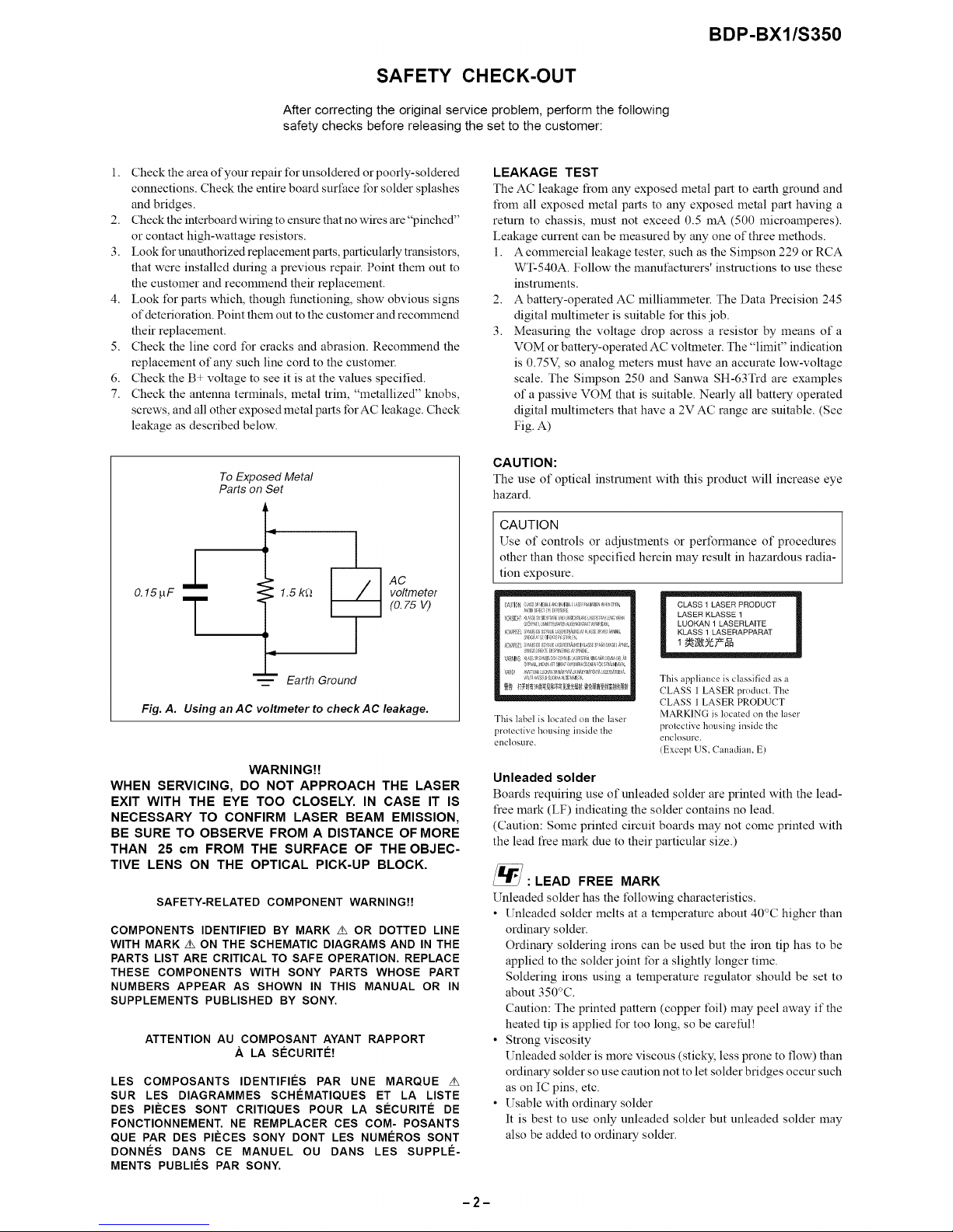
3. Measuring the voltage drop across a resistor by means of a
VOM or battery-operated AC voltmeter. The "limit" indication
is 0.75V, so analog meters must have an accurate low-voltage
scale. The Simpson 250 and Sanwa SH-63Trd are examples
of a passive VOM that is suitable. Nearly all battery operated
digital multimeters that have a 2V AC range are suitable. (See
Fig. A)
To Exposed Metal
Parts on Set
0.15pF T
1.5 k_
i
m Earth Ground
AC
voltmeter
(0.75 V)
Fig. A. Using an AC voltmeter to check AC leakage.
WARNING!!
WHEN SERVICING, DO NOT APPROACH THE LASER
EXIT WITH THE EYE TOO CLOSELY. IN CASE IT IS
NECESSARY TO CONFIRM LASER BEAM EMISSION,
BE SURE TO OBSERVE FROM A DISTANCE OF MORE
THAN 25 cm FROM THE SURFACE OF THE OBJEC-
TIVE LENS ON THE OPTICAL PICK-UP BLOCK.
SAFETY-RELATED COMPONENT WARNINGH
COMPONENTS IDENTIFIED BY MARK z_ OR DOTTED LINE
WITH MARK z_ ON THE SCHEMATIC DIAGRAMS AND IN THE
PARTS LIST ARE CRITICAL TO SAFE OPERATION. REPLACE
THESE COMPONENTS WITH SONY PARTS WHOSE PART
NUMBERS APPEAR AS SHOWN IN THIS MANUAL OR IN
SUPPLEMENTS PUBLISHED BY SONY.
ATTENTION AU COMPOSANT AYANT RAPPORT
.&. LA SECURITE!
LES COMPOSANTS IDENTIFIF:S PAR UNE MARQUE z_
SUR LES DIAGRAMMES SCHF:MATIQUES ET LA LISTE
DES PI#CES SONT CRITIQUES POUR LA SECURITE DE
FONCTIONNEMENT. NE REMPLACER CES COM- POSANTS
QUE PAR DES PI#CES SONY DONT LES NUMEROS SONT
DONNF:S DANS CE MANUEL OU DANS LES SUPPLE-
MENTS PUBLIES PAR SONY.
CAUTION:
The use of optical instrument with this product will increase eye
hazard.
CAUTION
Use of controls or adjustments or performance of procedures
other than those specified herein may result in hazardous radia-
tion exposure.
OJ*gTI0blC{_S3_'4SISLE_NI 'IqlBL£bS_ab01_ll0 A _'s'Erl,
¢,,,'01DDIAEC; E D2C%U E
k_ORSIOI_SS31aCIBRI)_SICII;IP,-#bSP,_NSZ_
Gg A f._lt L_:_ N&lG_l_0 &_ _ _HI:EL
AOV_ S L S_LI 0G gS% LI( L_ RST?]¢I4 I,F _L_SE 2_ ,'E#_NI[I(.
D [J£[ I PASIA i.
IO',/A_S[I S_ LICO;dS_LIG_SE£SI_IALH_;IL_;SF3R_A_EL _Pf_ES
_{g', I KJ EKSP0t, RNS !'!Etl.
VARHN_
'1_ _LI, N I _' a XP01F_r)C0_E_ # Si!_ALNI4G _,
','_RO
This label is located on the laser
proleclive housing inside the
enclosure.
CLASS 1 LASER PRODUCT
LASER KLASSE 1
LUOKAN 1 LASERLAITE
KLASS 1 LASERAPPARAT
This appliance is classified as a
CLASS 1 LASER product. The
CLASS 1 LASER PRODUCT
MARKING is located on the laser
protective housing inside the
enclosure.
(Except US, Canadian. E)
Unleaded solder
Boards requiring use of unleaded solder are printed with the lead-
tree mark (LF) indicating the solder contains no lead.
(Caution: Some printed circuit boards may not come printed with
the lead tree mark due to their particular size.)
:LEAD FREE MARK
Unleaded solder has the following characteristics.
• Unleaded solder melts at a temperature about 40°C higher than
ordinary solder.
Ordinary soldering irons can be used but the iron tip has to be
applied to the solder joint tbr a slightly longer time.
Soldering irons using a temperature regulator should be set to
about 350°C.
Caution: The printed pattern (copper foil) may peel away if the
heated tip is applied for too long, so be careful!
• Strong viscosity
Unleaded solder is more viscous (sticky, less prone to flow) than
ordinary solder so use caution not to let solder bridges occur such
as on IC pins, etc.
• Usable with ordinary solder
It is best to use only unleaded solder but unleaded solder may
also be added to ordinary solder.
-2-

BDP-BX1/S350
TABLE OF
Section Title PaQe
1. SERVICE NOTE
1-1. Disc Removal Procedure If The Tray Cannot Be
Ejected (Forced Ejection) ............................................. 1-1
1-2. Attention at installation of harness (DM-146) ............... 1-1
1-3. Test Disc ....................................................................... 1-2
1-3-1. Operation and Display ............................................. 1-2
2. DISASSEMBLY
2-1. Disassembly Flow ........................................................ 2-1
2-2. Upper Case .................................................................. 2-1
2-3. Tray CoverAssy ........................................................... 2-2
2-4. Front PanelAssy .......................................................... 2-2
2-5. IFD-003 Board .............................................................. 2-3
2-6. Front Chassis Block ..................................................... 2-3
2-7. Rear Panel Block .......................................................... 2-4
2-8. Switching Regulator ..................................................... 2-4
2-9. BD Drive ....................................................................... 2-5
2-10. MB-124 Board .............................................................. 2-5
2-11. Circuit Boards Location ................................................ 2-6
3. BLOCK DIAGRAMS
3-1. Overall Block Diagram (1/2) ......................................... 3-1
3-2. Overall Block Diagram (2/2) ......................................... 3-2
3-3. DSP Block Diagram ...................................................... 3-3
3-4. A/V OUT Block Diagram ............................................... 3-4
3-5. USB/ETHER Block Diagram ........................................ 3-5
3-6. IT Block Diagram .......................................................... 3-6
3-7. Power Block Diagram (1/2) .......................................... 3-7
3-8. Power Block Diagram (2/2) .......................................... 3-8
4. SCHEMATIC DIAGRAMS
4-1. This Note Is Common For Schematic Diagrams .......... 4-1
4-2. Frame Schematic Diagram ........................................... 4-2
4-3. AV-123 Board (AUDIO OUT)
Schematic Diagram (1/2) .............................................. 4-3
4-4. AV-123 Board (VIDEO OUT)
Schematic Diagram (2/2) .............................................. 4-4
4-5. FC-096 Board (LED) Schematic Diagram .................... 4-5
4-6. FL-187 Board (SWITCH) Schematic Diagram ............. 4-6
4-7. FR-294 Board (FL DRIVER)
Schematic Diagram ...................................................... 4-7
4-8. IFD-003 Board (POWER)
Schematic Diagram (1/3) .............................................. 4-8
4-9. IFD-003 Board (IF CONTROLLER)
Schematic Diagram (2/3) .............................................. 4-9
4-10. IFD-003 Board (FAN) Schematic Diagram (3/3) ........... 4-10
4-11. MB-124 Board (EMMA3P DDR2-A)
Schematic Diagram (1/11) ............................................ 4-11
4-12. MB-124 Board (EMMA3P DDR2-B)
Schematic Diagram (2/11) ............................................ 4-12
4-13. MB-124 Board (POWER1)
Schematic Diagram (3/11) ............................................ 4-13
4-14. MB-124 Board (CLK/POWER2)
CONTENTS
Section Title Paqe
Schematic Diagram (4/11) ............................................ 4-14
4-15. MB-124 Board (FLASH/HOST)
Schematic Diagram (5/11) ............................................ 4-15
4-16. MB-124 Board (USB) Schematic Diagram (6/11) ......... 4-16
4-17. MB-124 Board (HDMI/SATA)
Schematic Diagram (7/11) ............................................ 4-17
4-18. MB-124 Board (AUDIO/VIDEO)
Schematic Diagram (8/11) ............................................ 4-18
4-19. MB-124 Board (GPIO/JTAG)
Schematic Diagram (9/11) ............................................ 4-19
4-20. MB-124 Board (IPIO)
Schematic Diagram (10/11) .......................................... 4-20
4-21. MB-124 Board (ETHERNET)
Schematic Diagram (11/11) .......................................... 4-21
4-22. USB-008 Board (USB CONNECTOR)
Schematic Diagram ...................................................... 4-22
4-23. Waveforms ................................................................... 4-23
5. PRINTED WIRING BOARDS
5-1. This Note Is Common For Printed Wiring Boards ........ 5-1
5-2. AV-123 Board (AUDIO/VIDEO OUT)
Printed Wiring Board (Side A) ...................................... 5-2
5-3. AV-123 Board (AUDIO/VIDEO OUT)
Printed Wiring Board (Side B) ...................................... 5-3
5-4. FC-096 Board (LED) Printed Wiring Board .................. 5-4
5-5. FL-187 Board (SWITCH) Printed Wiring Board ............ 5-5
5-6. FR-294 Board (FL DRIVER)
Printed Wiring Board (Side A) ...................................... 5-6
5-7. FR-294 Board (FL DRIVER)
Printed Wiring Board (Side B) ...................................... 5-7
5-8. IFD-003 Board (IF CONTROLLER)
Printed Wiring Board (Side A) ...................................... 5-8
5-9. IFD-003 Board (IF CONTROLLER)
Printed Wiring Board (Side B) ...................................... 5-9
5-10. MB-124 Board (MAIN)
Printed Wiring Board (Side A) ...................................... 5-10
5-11. MB-124 Board (MAIN)
Printed Wiring Board (Side B) ...................................... 5-11
5-12. USB-008 Board (USB CONNECTOR)
Printed Wiring Board .................................................... 5-12
6. IC PIN FUNCTION DESCRIPTION ................... 6-1
7. SERVICE MODE ..................................................... 7-1
8. ERROR LOG LIST ............................................ 8-1
9. TROUBLESHOOTING ............................................. 9-1
10. REPAIR PARTS LIST
10-1. Exploded Views ............................................................ 10-1
10-1-1. Case Section ......................................................... 10-1
10-1-2. Front/Rear Chassis Section .................................. 10-2
10-1-3. Main Chassis Section ............................................ 10-3
10-1-4. Accessories ........................................................... 10-4
10-2. Electrical Parts List ..................................................... 10-5
-3-
1-1.
1.
2.
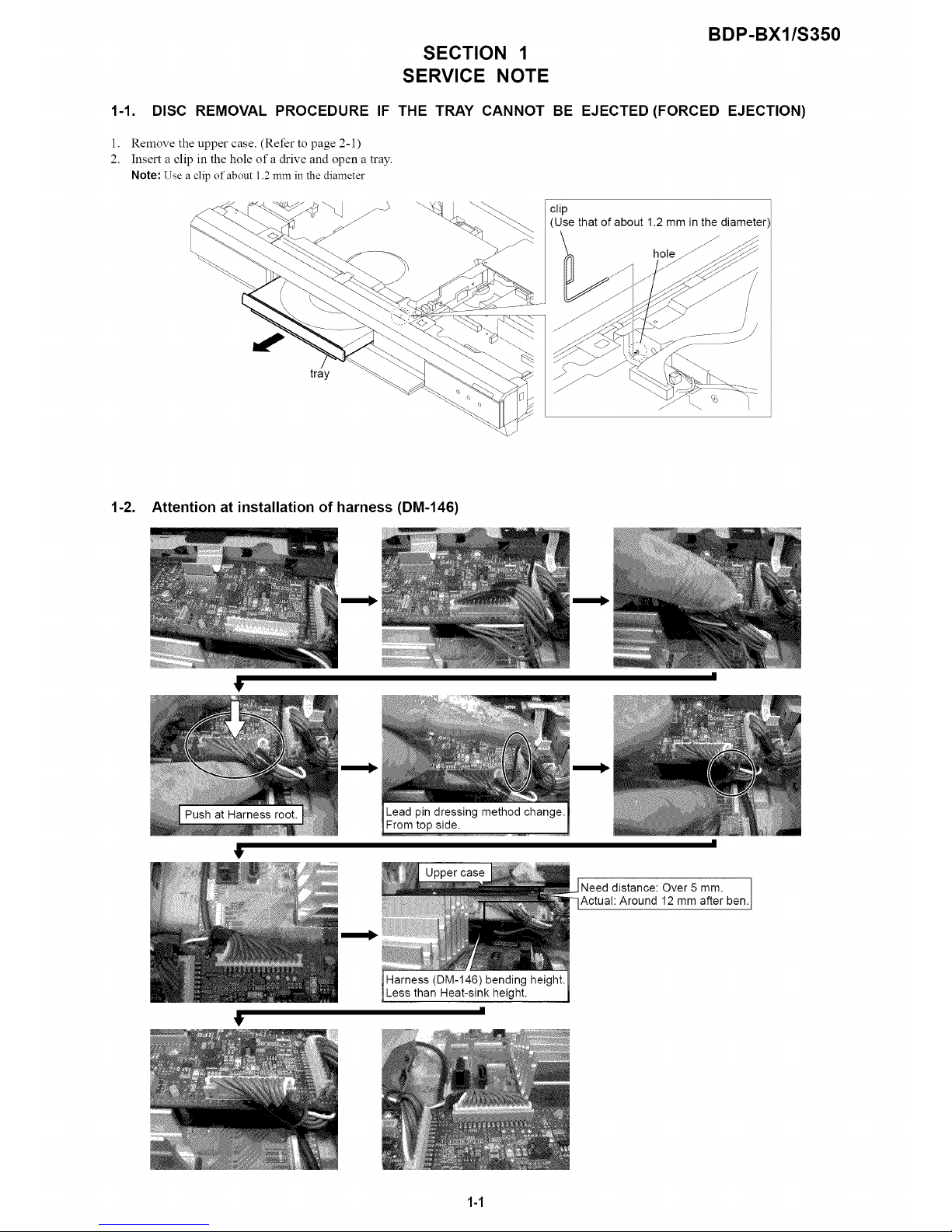
DISC REMOVAL PROCEDURE
SECTION 1
SERVICE NOTE
BDP-BX1/S350
IF THE TRAY CANNOT BE EJECTED (FORCED EJECTION)
Remove the upper case. (Refer to page 2-1)
Insert a clip in the hole of a drive and open a tray.
Note: Use a clip of about 1.2 mm in the diameter
clip
(Use that of about 1.2 mm in the diameter'
\
hole
tray
1-2. Attention at installation of harness (DM-146)
1!'
t
Lead pin dressing method change.
From top side.
Uppercase
Need distance: Over 5 mm. ben.Actual: Around 12 mm after
Harness (DM-146) bending height.
Less than Heat-sink height.
|
1-1
BDP-BX1/S350
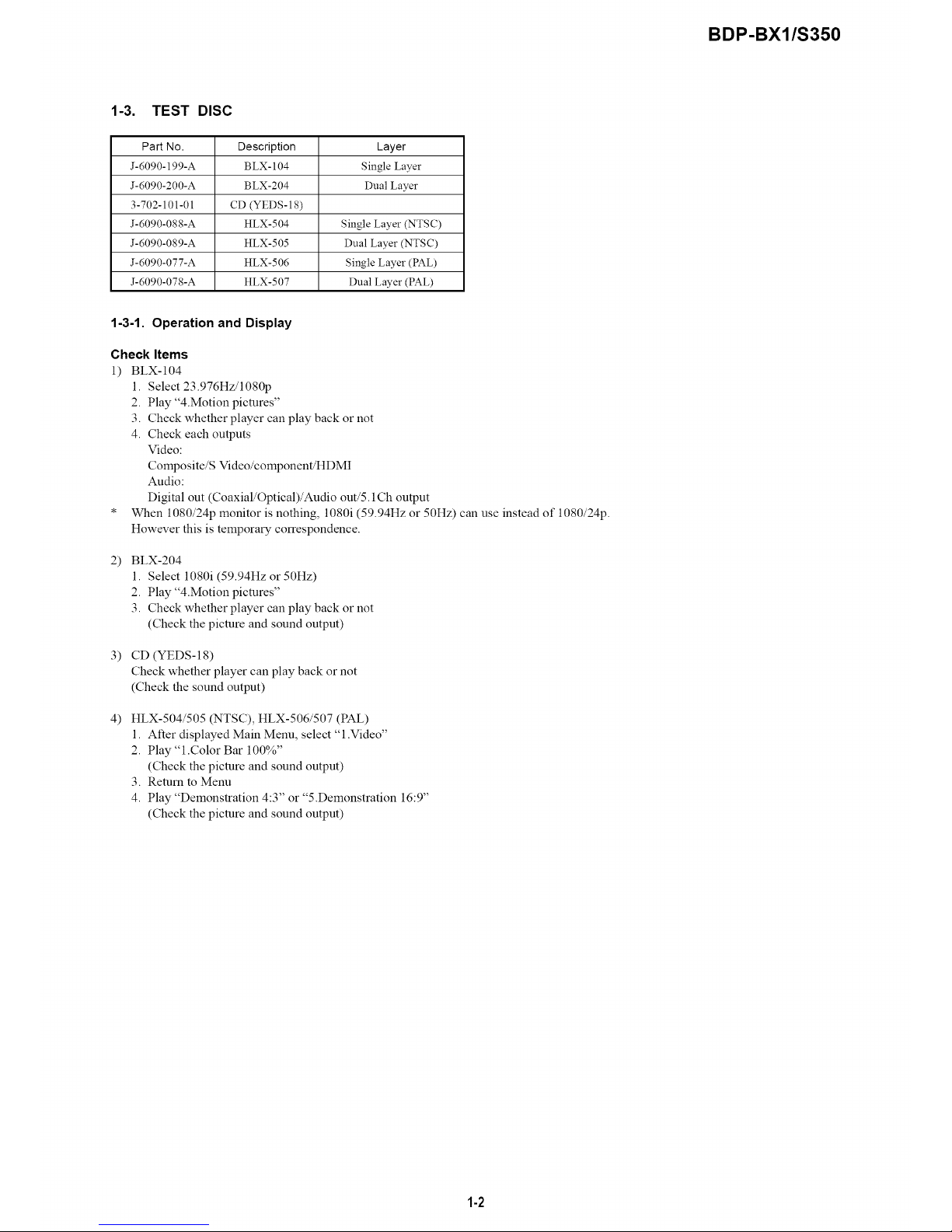
1-3. TEST DISC
Part No. Description Layer
J-6090-199-A B LX- 104 Single Layer
J-6090-200-A BLX-204 Dual Layer
3-702-101-01 CD (YEDS-18)
J-6090-088-A HLX-504 Single Layer (NTSC)
J-6090-089-A HLX-505 Dual Layer (NTSC)
J-6090-077-A HLX-506 Single Layer (PAL)
J-6090-078-A HLX-507 Dual Layer (PAL)
1-3-1. Operation and Display
Check Items
1) BLX-104
1. Select 23.976Hz/1080p
2. Play "4.Motion pictures"
3. Check whether player can play back or not
4. Check each outputs
Video:
Composite/S Video/component/HDMI
Audio:
Digital out (Coaxial/Optical)/Audio out/5.1Ch output
* When 1080/24p monitor is nothing, 1080i (59.94Hz or 50Hz) can use instead of 1080/2@.
However this is temporary correspondence.
2)
BLX-204
1. Select 1080i (59.94Hz or 50Hz)
2. Play "4.Motion pictures"
3. Check whether player can play back or not
(Check the picture and sound output)
3) CD (YEDS-18)
Check whether player can play back or not
(Check the sound output)
4) HLX-504/505 (NTSC), HLX-506/507 (PAL)
1. After displayed Main Menu, select "l.Video"
2. Play "l.Color Bar 100%"
(Check the picture and sound output)
3. Remm to Menu
4. Play "Demonstration 4:3" or "5.Demonstration 16:9"
(Check the picture and sound output)
1-2
BDP-BX1/S350
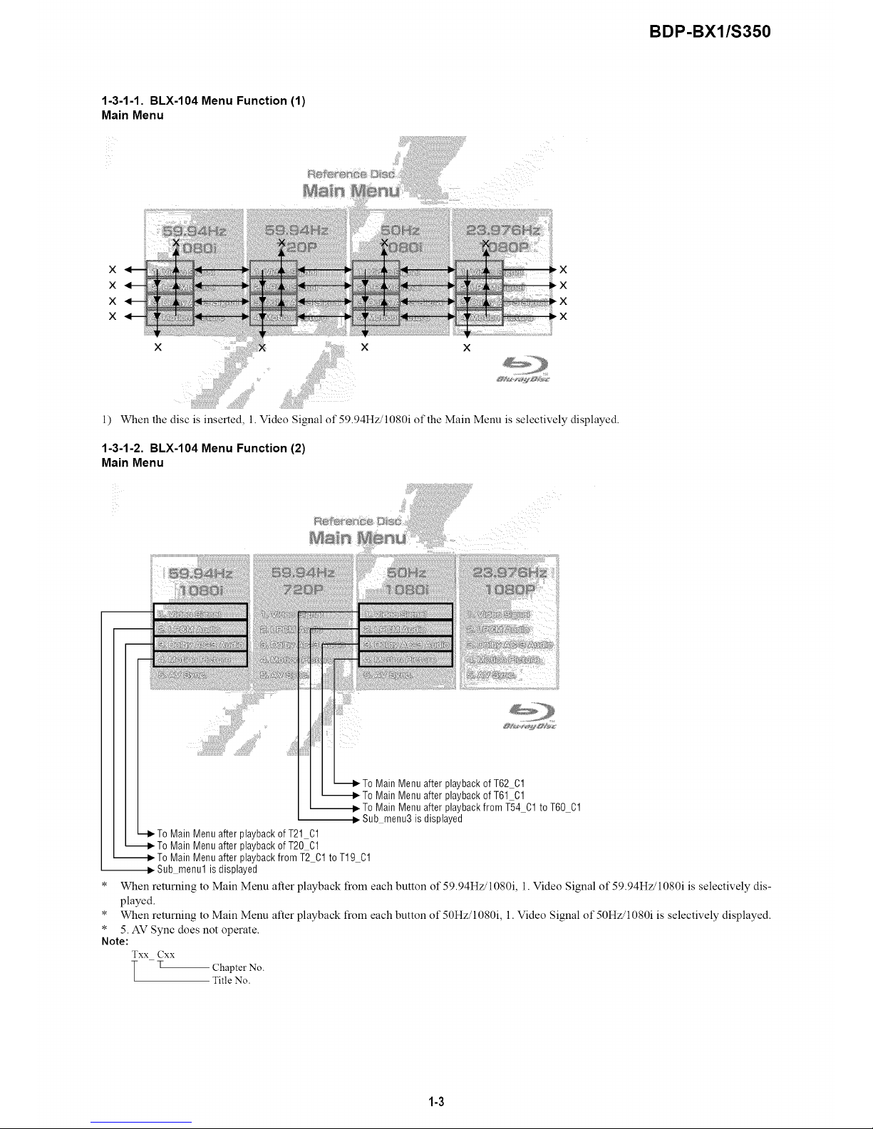
1-3-1-1. BLX-104 Menu Function (1)
Main Menu
x
x
x
x
,x
_X
1)
x ii!iiii x x
When the disc is inserted, 1. Video Signal of 59.94Hz/1080i of the Main Menu is selectively displayed.
1-3-1-2. BLX-104 Menu Function (2)
Main Menu
Note:
Txx Cxx
T •
Menu after playbackof T62 Cl
Menu after playbackof T61 Cl
To Main Menu after playbackfrom T54 01 to T60 01
Sub menu3 isdisplayed
Main Menu after playbackof T21 01
Main Menu after playbackof T20 01
Main Menu after playbackfrom T2 01to T19 01
Sub menu1 is displayed
When returning to Main Menu after playback from each button of 59.94Hz/1080i, l. Video Signal of 59.94Hz/1080i is selectively dis-
played.
When returning to Main Menu after playback from each button of 50Hz/1080i, 1. Video Signal of 50Hz/1080i is selectively displayed.
5. AV Sync does not operate.
Chapter No.
Title No.
1-3
BDP-BX1/S350
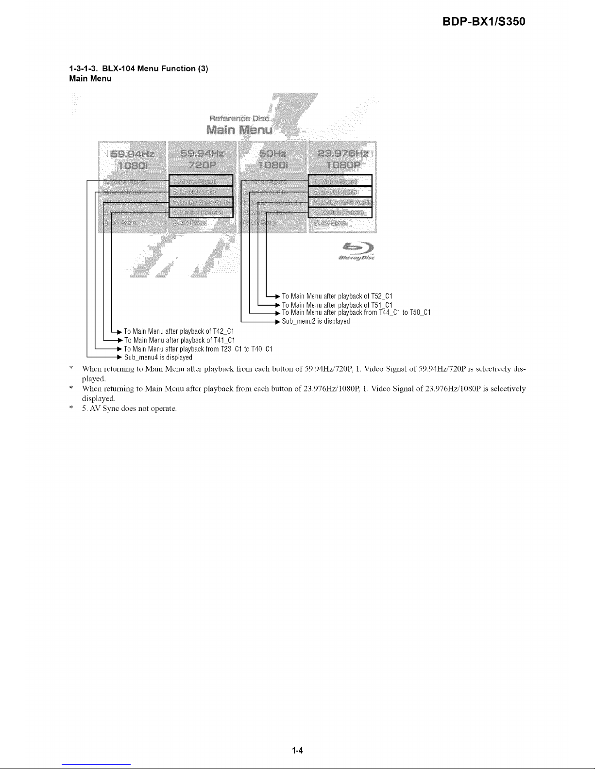
1-3-1-3. BLX-104 Menu Function (3)
Main Menu
ToMain Menu after playbackof T52 Cl
_To Main Menuafter playbackof T51 Cl
_To Main Menuafter playbackfrom T44 C1 to T50 C1
... Sub menu2is displayed
-I_To MainMenu after playbackof T42 Cl
_To MainMenu after playbackof T41 01
_To MainMenu after playbackfrom T23 01 to T40 01
,_ Sub menu4is displayed
* When returning to Main Menu alter playback from each button of 59.94Hz/720P, l. Video Signal of 59.94Hz/720P is selectively dis-
played.
* When returning to Main Menu alter playback from each button of 23.976Hz/1080R 1. Video Signal of 23.976Hz/1080P is selectively
displayed.
* 5. AV Sync does not operate.
1-4

BDP-BX1/S350
1-3-1-4. BLX-104 Menu Function (4)
Sub menu1
x_
_X
x
1) At the display of Sub menul, 1. Color Bar 100% is selectively displayed.
2) Selection of 1. Color Bar 100% -+ Return to Sub menul after seamless playback from TI CI to TI C13. 1. Color Bar 100% is selec-
tively displayed on Sub menu 1 screen.
3) Selection of 2. Color Bar 75% -+ Return to Sub menu I after seamless playback from T 1 C2 to T 1 C 13. 1. Color Bar 100% is selectively
displayed on Sub menu I screen.
4) At the selection of 3 - 13, item 3 mentioned above is executed as the routine.
5) At the display of Sub menu 1, Main Menu is selected -+ Jump to Main Menu. At the display of Main Menu, 1. Video Signal of 59.94Hz/
1080i is selectively displayed.
6) Selection of LPCM Audio -+ Playback from T2 C 1 to T 19 C 1. SubPic that corresponds to Audio stream 1 is tbrcibly displayed.
During the playback, when audio channel changes, the caption that corresponds to each audio stream is tbrcibly displayed. Return to
Sub menul after playback. 1. Color Bar 100% is selectively displayed on Sub menul screen.
7) Selection of Dolby AC-3 Audio -+ Playback of T20 C 1. SubPic that corresponds to Audio stream 1 is tbrcibly displayed.
During the playback, when audio channel changes, the caption that corresponds to each audio stream is lbrcibly displayed. Return to
Sub menul after playback. 1. Color Bar 100% is selectively displayed on Sub menul screen.
8) Selection of Motion Picture -+ Return to Sub menul after playback ofT21 CI. 1. ColorBar 100% is selectively displayed on Sub
menu I screen.
9) At the selection of Main Menu, 1. VideoSignal of 1080/59.94i of Main Menu is selectively displayed.
10) AV Sync does not operate.
1-5

BDP-BX1/S350
1-3-1-5. BLX-104 Menu Function (5)
Sub menu2
X_
×
X
1) At the display of Sub menu2, 1. Color Bar 100% is selectively displayed.
2) Selection of 1. Color Bar 100% --* Return to Sub menu2 after seamless playback from T43 CI to T43 C13. 1. Color Bar 100% is
selectively displayed on Sub menu2 screen.
3) Selection of 2. Color Bar 75% --* Return to Sub menu2 after seamless playback from T43 C2 to T43 C13. 1. Color Bar 100% is se-
lectively displayed on Sub menu2 screen.
4) At the selection of 3 - 13, item 3 mentioned above is executed as the routine.
5) At the display of Sub menu2, Main Menu is selected --* Jump to Main Menu. At the display of Main Menu, 1. Video Signal of 23.976Hz/
1080P is selectively displayed.
6) Selection of LPCM Audio --* Playback from T44 C 1 to T50 C 1. SubPic that corresponds to Audio stream 1 is lbrcibly displayed.
During the playback, when audio channel changes, the caption that corresponds to each audio stream is lbrcibly displayed. Return to
Sub menu2 after playback. 1. Color Bar 100% is selectively displayed on Sub menu2 screen.
7) Selection of Dolby AC-3 Audio --* Playback of T51 C 1. SubPic that corresponds to Audio stream 1 is forcibly displayed.
During the playback, when audio channel changes, the caption that corresponds to each audio stream is lbrcibly displayed. Return to
Sub menu2 after playback. 1. Color Bar 100% is selectively displayed on Sub menu2 screen.
8) Selection of Motion Picture --* Return to Sub menu2 after playback of T52 C 1. 1. Color Bar 100% is selectively displayed on Sub
menu2 screen.
9) At the selection of Main Menu, 1. Video Signal of 1080/23.976P of Main Menu is selectively displayed.
10) AV Sync does not operate.
1-6

BDP-BX1/S350
1-3-1-6. BLX-104 Menu Function (6)
Sub menu3
×
X_
_r
×
1) At the display of Sub menu3, 1. Color Bar 100% is selectively displayed.
2) Selection of 1. Color Bar 100% --* Return to Sub menu3 after seamless playback from T53 CI to T53 C13. 1. Color Bar 100% is
selectively displayed on Sub menu3 screen.
3) Selection of 2. Color Bar 75% --* Return to Sub menu3 after seamless playback from T53 C2 to T53 C13. l. Color Bar 100% is se-
lectively displayed on Sub menu3 screen.
4) At the selection of 3 - 13, item 3 mentioned above is executed as the routine.
5) At the display of Sub menu3, Main Menu is selected--* Jump to Main Menu. At the display of Main Menu, 1. Video Signal of50Hz/1080i
is selectively displayed.
6) Selection of LPCM Audio --+ Playback from T54 C1 to T60 C 1. SubPic that corresponds to Audio stream 1 is forcibly displayed.
During the playback, when audio channel changes, the caption that corresponds to each audio stream is forcibly displayed. Return to
Sub menu3 after playback. 1. Color Bar 100% is selectively displayed on Sub menu3 screen.
7) Selection of Dolby AC-3 Audio --+ Playback of T61 C 1. SubPic that corresponds to Audio stream 1 is forcibly displayed.
During the playback, when audio channel changes, the caption that corresponds to each audio stream is forcibly displayed. Return to
Sub menu3 after playback. 1. Color Bar 100% is selectively displayed on Sub menu3 screen.
8) Selection of Motion Picture --+ Return to Sub menu3 after playback of T62 C1. 1. Color Bar 100% is selectively displayed on Sub
menu3 screen.
9) At the selection of Main Menu, 1. Video Signal of 1080/50i of Main Menu is selectively displayed.
10) AV Sync does not operate.
1-7
BDP-BX1/S350
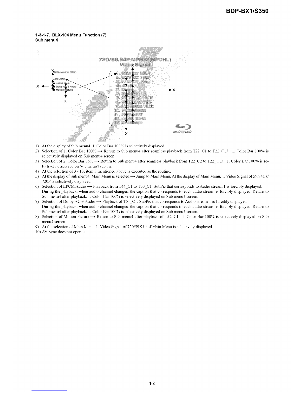
1-3-1-7. BLX-104 Menu Function (7)
Sub menu4
x_
x
1) At the display of Sub menu4, 1. Color Bar 100% is selectively displayed.
2) Selection of 1. Color Bar 100% --_ Return to Sub menu4 after seamless playback from T22 C1 to T22 C13. 1. Color Bar 100% is
selectively displayed on Sub menu4 screen.
3) Selection of 2. Color Bar 75% --_ Return to Sub menu4 after seamless playback from T22 C2 to T22 C13. 1. Color Bar 100% is se-
lectively displayed on Sub menu4 screen.
4) At the selection of 3 - 13, item 3 mentioned above is executed as the routine.
5) At the display of Sub menu4, Main Menu is selected --_ Jump to Main Menu. At the display of Main Menu, 1. Video Signal of 59.94Hz/
720P is selectively displayed.
6) Selection of LPCM Audio --_ Playback from T44 C 1 to T50 C 1. SubPic that corresponds to Audio stream 1 is forcibly displayed.
During the playback, when audio channel changes, the caption that corresponds to each audio stream is forcibly displayed. Return to
Sub menu4 after playback. 1. Color Bar 100% is selectively displayed on Sub menu4 screen.
7) Selection of Dolby AC-3 Audio --_ Playback of T51 C 1. SubPic that corresponds to Audio stream 1 is forcibly displayed.
During the playback, when audio channel changes, the caption that corresponds to each audio stream is forcibly displayed. Return to
Sub menu4 after playback. 1. Color Bar 100% is selectively displayed on Sub menu4 screen.
8) Selection of Motion Picture --_ Return to Sub menu4 after playback of T52 C1. 1. Color Bar 100% is selectively displayed on Sub
menu4 screen.
9) At the selection of Main Menu, 1. Video Si_,nal of 720/59.94P of Main Menu is selectively displayed.
10) AV Sync does not operate.
1-8
BDP-BX1/S350
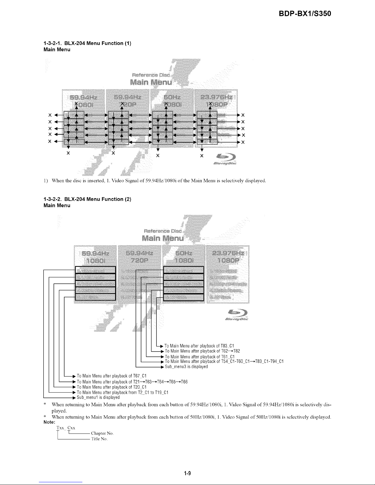
1-3-2-1. BLX-204 Menu Function (1)
Main Menu
X
X
X
X
X
1) When the disc is inserted, 1. Video Signal of 59.94Hz/1080i of the Main Menu is selectively displayed.
1-3-2-2. BLX-204 Menu Function (2)
Main Menu
ii!i!i;i
Note:
Txx Cxx
T •
,To Main Menuafter playbackof T83 01
Main Menu after playbackof T62--*T82
Main Menu after playbackof T61 01
To Main Menu after playbackof T54 01-T60 01--*T83 01-T94 01
Sub menu3 is displayed
• To MainMenu after playbackof T67 01
MainMenu after playbackof T21--*T63--*T64--*T65--*T66
MainMenu after playbackof T20 Cl
,_ To MainMenu after playbackfrom T2 Cl to T19 01
Sub menu1 is displayed
When returning to Main Menu after playback from each button of 59.94Hz/1080i, 1. Video Signal of 59.94Hz/1080i is selectively dis-
played.
When returning to Main Menu after playback from each button of 50Hz/1080i, 1. Video Signal of 50Hz/1080i is selectively displayed.
Chapter No.
Title No.
1-9
BDP-BX1/S350
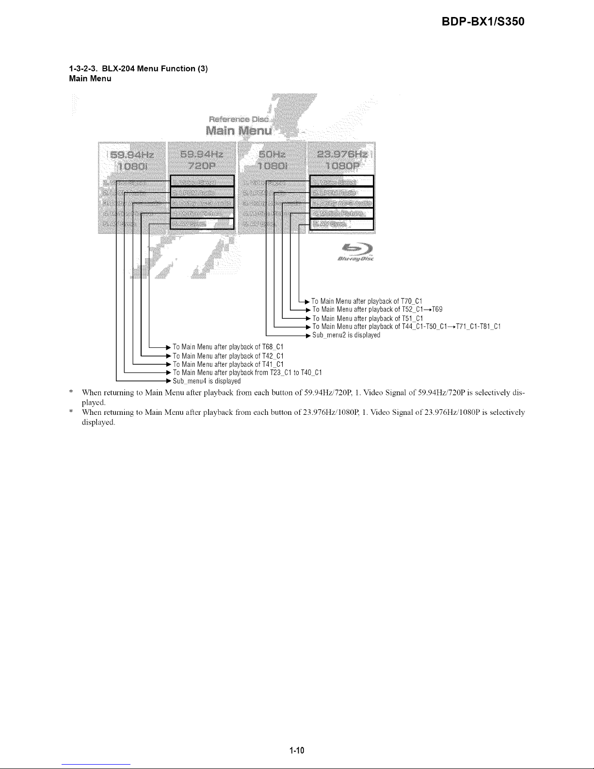
1-3-2-3. BLX-204 Menu Function (3)
Main Menu
_To Main Menuafter playback ofT68 01
_To MainMenu after playback of T42 01
_- To MainMenu after playback of T41 01
_To Main Menu after playbackof T70 01
To Main Menu after playbackof T52 01--,T69
To Main Menu after playbackof T51 01
To Main Menu after playback ofT44 01-T50 01--,T71 01-T81 01
Sub menu2 is displayed
To Main Menuafter playback from T23 01 to T40 01
• Sub menu4is displayed
When returning to Main Menu alter playback from each button of 59.94Hz/720P, l. Video Signal of 59.94Hz/720P is selectively dis-
played.
When returning to Main Menu alter playback from each button of 23.976Hz/1080R 1. Video Signal of 23.976Hz/1080P is selectively
displayed.
1-10

BDP-BX1/S350
1-3-2-4. BLX-204 Menu Function (4)
Sub menu 1
X_--
1) At the display of Sub menul, 1. Color Bar 100% is selectively displayed.
2) Selection of 1. Color Bar 100% --* Return to Sub menul after seamless playback from T1 C1 to T1 C13. 1. Color Bar 100% is selec-
tively displayed on Sub menu 1 screen.
3) Selection of 2. Color Bar 75% --* Return to Sub menu 1 after seamless playback from T 1 C2 to T 1 C 13. 1. Color Bar 100% is selectively
displayed on Sub menu 1 screen.
4) At the selection of 3 - 13, item 3 mentioned above is executed as the routine.
5) At the display of Sub menu 1, Main Menu is selected --* Jump to Main Menu. At the display of Main Menu, 1. Video Signal of 59.94Hz/
1080i is selectively displayed.
6) Selection of LPCM Audio --* Playback from T2 C 1 to T 19 C 1. SubPic that corresponds to Audio stream 1 is forcibly displayed.
During the playback, when audio channel changes, the caption that corresponds to each audio stream is forcibly displayed. Return to
Sub menul after playback. 1. Color Bar 100% is selectively displayed on Sub menul screen.
7) Selection of Dolby AC-3 Audio --* Playback of T20 C 1. SubPic that corresponds to Audio stream 1 is forcibly displayed.
During the playback, when audio channel changes, the caption that corresponds to each audio stream is forcibly displayed. Return to
Sub menul after playback. 1. Color Bar 100% is selectively displayed on Sub menul screen.
8) Selection of Motion Picture --* Return to Sub menu l after playback of T21 C1. 1. Color Bar 100% is selectively displayed on Sub
menu 1 screen.
9) Selection ofAV Sync --* Return to Sub menul after playback ofT67 C1. 1. Color Bar 100% is selectively displayed on Sub menul
screen.
10) At the selection of Main Menu, 1. Video Signal of 1080/59.94i of Main Menu is selectively displayed.
1-11

BDP-BX1/S350
1-3-2-5. BLX-204 Menu Function (5)
Sub menu 2
x_
X
_.X
1) At the display of Sub menu2, 1. Color Bar 100% is selectively displayed.
2) Selection of 1. Color Bar 100% --* Return to Sub menu2 after seamless playback from T43 C1 to T43 C13. 1. Color Bar 100% is
selectively displayed on Sub menu2 screen.
3) Selection of 2. Color Bar 75% --* Return to Sub menu2 after seamless playback from T43 C2 to T43 C13. 1. Color Bar 100% is se-
lectively displayed on Sub menu2 screen.
4) At the selection of 3 - 13, item 3 mentioned above is executed as the routine.
5) At the display of Sub menu2, Main Menu is selected --* Jump to Main Menu. At the display of Main Menu, 1. Video Signal of 23.976Hz/
1080P is selectively displayed.
6) Selection of LPCM Audio --* Playback from T44 C 1 to T50 C 1 and from T71 C 1 to T81 C 1. SubPic that corresponds to Audio stream
1 is forcibly displayed.
During the playback, when audio channel changes, the caption that corresponds to each audio stream is forcibly displayed. Return to
Sub menu2 alter playback. 1. Color Bar 100% is selectively displayed on Sub menu2 screen.
7) Selection of Dolby AC-3 Audio --* Playback of T51 C 1. SubPic that corresponds to Audio stream 1 is forcibly displayed.
During the playback, when audio channel changes, the caption that corresponds to each audio stream is forcibly displayed. Return to
Sub menu2 alter playback. 1. Color Bar 100% is selectively displayed on Sub menu2 screen.
8) Selection of Motion Picture --* Return to Sub menu2 after playback ofT52 C 1 and T69. 1. Color Bar 100% is selectively displayed on
Sub menu2 screen.
9) Selection ofAV Sync --* Return to Sub menu2 after playback ofT70 C1. 1. Color Bar 100% is selectively displayed on Sub menu2
screen.
10) At the selection of Main Menu, 1. Video Signal of 1080/23.976P of Main Menu is selectively displayed.
1-12
BDP-BX1/S350
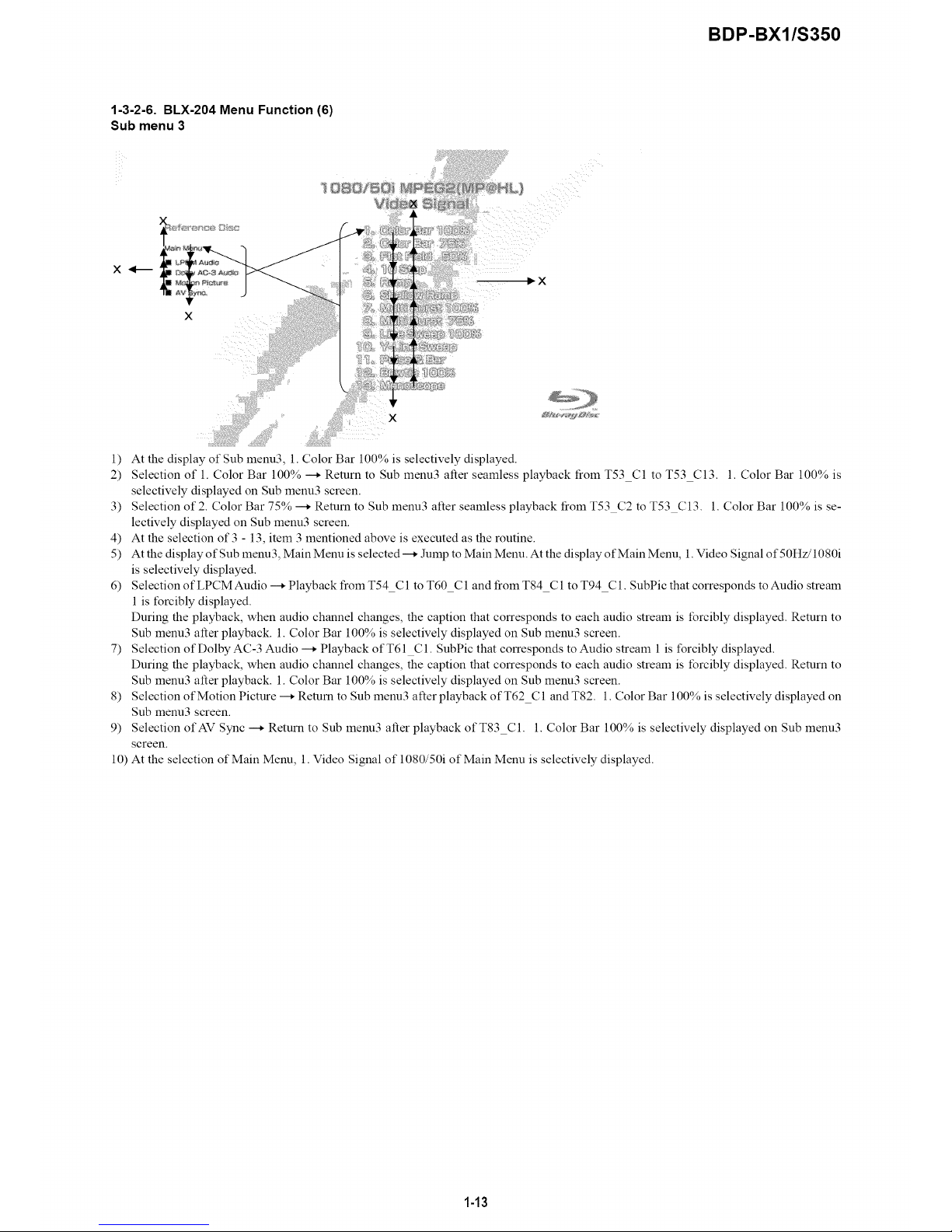
1-3-2-6. BLX-204 Menu Function (6)
Sub menu 3
X_--
_X
1) At the display of Sub menu3, 1. Color Bar 100% is selectively displayed.
2) Selection of 1. Color Bar 100% --_ Return to Sub menu3 alter seamless playback from T53 C1 to T53 C13. 1. Color Bar 100% is
selectively displayed on Sub menu3 screen.
3) Selection of 2. Color Bar 75% --_ Return to Sub menu3 alter seamless playback from T53 C2 to T53 C13. 1. Color Bar 100% is se-
lectively displayed on Sub menu3 screen.
4) At the selection of 3 - 13, item 3 mentioned above is executed as the routine.
5) At the display of Sub menu3, Main Menu is selected --* Jump to Main Menu. At the display of Main Menu, 1. Video Signal of50Hz/1080i
is selectively displayed.
6) Selection of LPCM Audio --* Playback from T54 C 1 to T60 C 1 and from T84 C 1 to T94 C 1. SubPic that corresponds to Audio stream
1 is forcibly displayed.
During the playback, when audio channel changes, the caption that corresponds to each audio stream is forcibly displayed. Return to
Sub menu3 alter playback. 1. Color Bar 100% is selectively displayed on Sub menu3 screen.
7) Selection of Dolby AC-3 Audio --* Playback of T61 C 1. SubPic that corresponds to Audio stream 1 is forcibly displayed.
During the playback, when audio channel changes, the caption that corresponds to each audio stream is forcibly displayed. Return to
Sub menu3 alter playback. 1. Color Bar 100% is selectively displayed on Sub menu3 screen.
8) Selection of Motion Picture --* Return to Sub menu3 alter playback ofT62 C 1 and T82. 1. Color Bar 100% is selectively displayed on
Sub menu3 screen.
9) Selection ofAV Sync --_ Return to Sub menu3 alter playback ofT83 C1. 1. Color Bar 100% is selectively displayed on Sub menu3
screen.
10) At the selection of Main Menu, 1. Video Signal of 1080/50i of Main Menu is selectively displayed.
1-13

BDP-BX1/S350
1-3-2-7. BLX-204 Menu Function (7)
Sub menu 4
X_
X
x
_@HL
IiX
1) At the display of Sub menu4, 1. Color Bar 100% is selectively displayed.
2) Selection of 1. Color Bar 100% --_ Return to Sub menu4 after seamless playback from T22 C1 to T22 C13. 1. Color Bar 100% is
selectively displayed on Sub menu4 screen.
3) Selection of 2. Color Bar 75% --_ Return to Sub menu4 after seamless playback from T22 C2 to T22 C13. 1. Color Bar 100% is se-
lectively displayed on Sub menu4 screen.
4) At the selection of 3 - 13, item 3 mentioned above is executed as the routine.
5) At the display of Sub menu4, Main Menu is selected --_ Jump to Main Menu. At the display of Main Menu, 1. Video Signal of 59.94Hz/
720P is selectively displayed.
6) Selection of LPCM Audio --_ Playback from T44 C 1 to T50 C 1. SubPic that corresponds to Audio stream 1 is forcibly displayed.
During the playback, when audio channel changes, the caption that corresponds to each audio stream is forcibly displayed. Return to
Sub menu4 after playback. 1. Color Bar 100% is selectively displayed on Sub menu4 screen.
7) Selection of Dolby AC-3 Audio --_ Playback of T51 C 1. SubPic that corresponds to Audio stream 1 is forcibly displayed.
During the playback, when audio channel changes, the caption that corresponds to each audio stream is forcibly displayed. Return to
Sub menu4 after playback. 1. Color Bar 100% is selectively displayed on Sub menu4 screen.
8) Selection of Motion Picture --_ Return to Sub menu4 after playback of T52 C1. 1. Color Bar 100% is selectively displayed on Sub
menu4 screen.
9) Selection ofAV Sync --_ Return to Sub menu4 after playback ofT68 C1. 1. Color Bar 100% is selectively displayed on Sub menu4
screen.
10) At the selection of Main Menu, 1. Video Si_,nal of 720/59.94P of Main Menu is selectively displayed.
1-14E
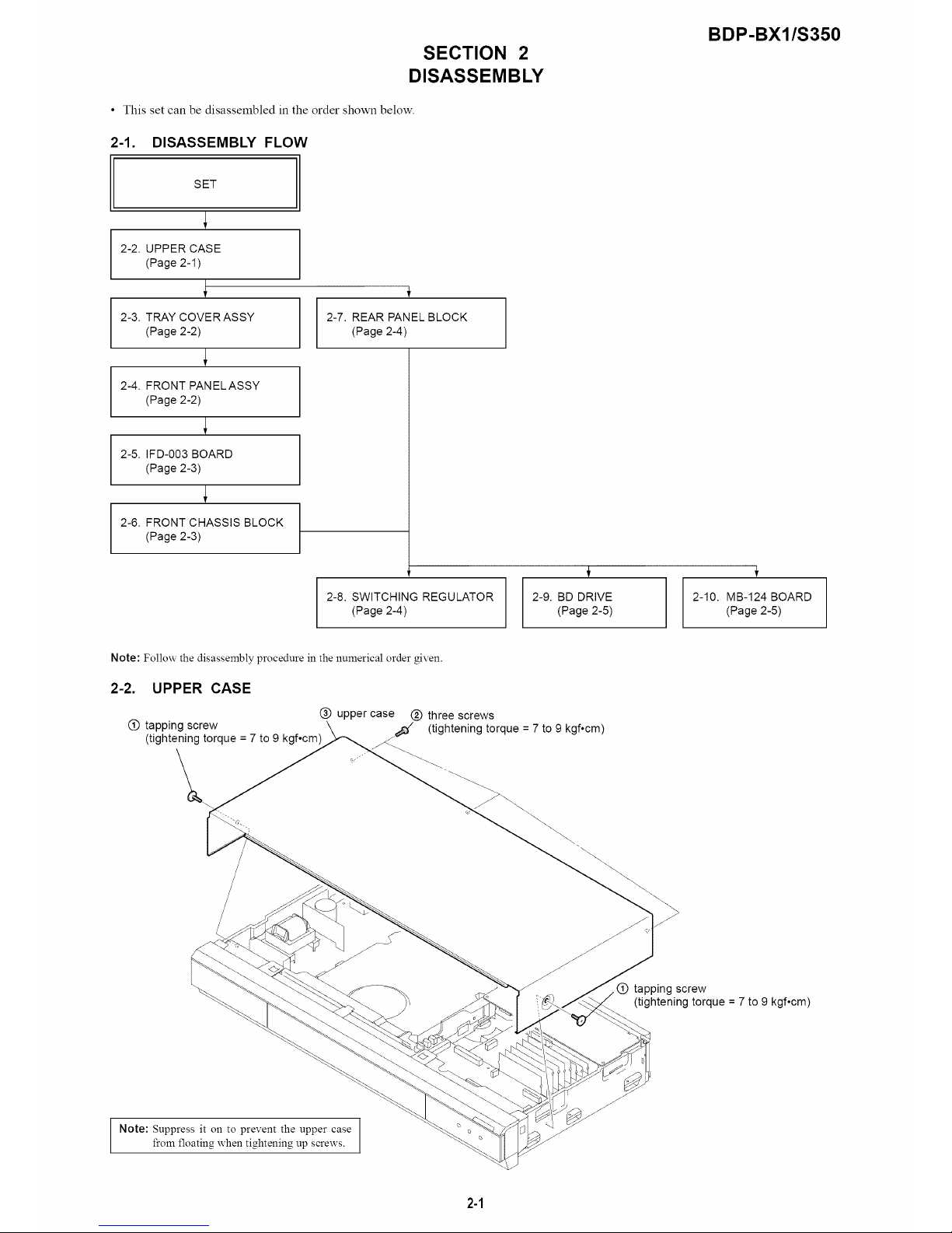
SECTION 2
DISASSEMBLY
• This set can be disassembled in the order shown below.
2-1. DISASSEMBLY FLOW
BDP-BX1/S350
SET
2-2. UPPER CASE
(Page 2-1)
2-3. TRAY COVERASSY
(Page 2-2)
2-4. FRONT PANELASSY
(Page 2-2)
2-5. IFD-003 BOARD
(Page 2-3)
2-6. FRONT CHASSIS BLOCK
(Page 2-3)
2-7. REAR PANEL BLOCK
(Page 2-4)
2-8. SWITCHING REGULATOR
(Page 2-4)
2-9. BD DRIVE
(Page 2-5)
÷
2-10. MB-124 BOARD
(Page 2-5)
Note: Follow the disassembly procedure in the numerical order given.
2-2. UPPER CASE
@ upper case @ three screws
@ tapping screw _ (tightening torque = 7 to 9 kgf.cm)
(tightening torque = 7 to 9 kgf°cm)
>
tapping screw
(tightening torque = 7 to 9 kgf°cm)
Note: Suppress it on to prevent the upper case
from floating when tightening up screws.
2-1
BDP-BX1/S350
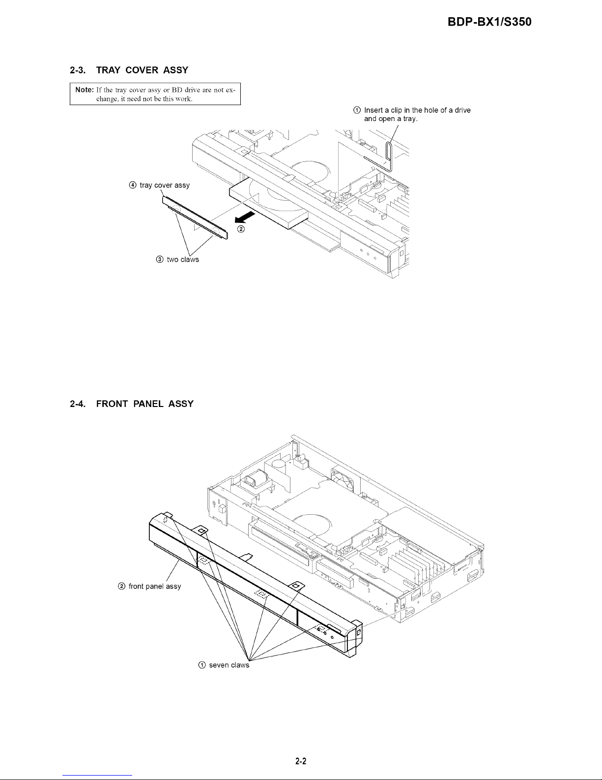
2-3. TRAY COVER ASSY
Note: If the tray cover assy or BD drive are not ex-
change, it need not be this work.
(_) Insert a clip in the hole of a drive
and open a tray.
@ tray cover assy
@
@ two claws
2-4. FRONT PANEL ASSY
@ front panel assy
@ seven claws
2-2
BDP-BX1/S350
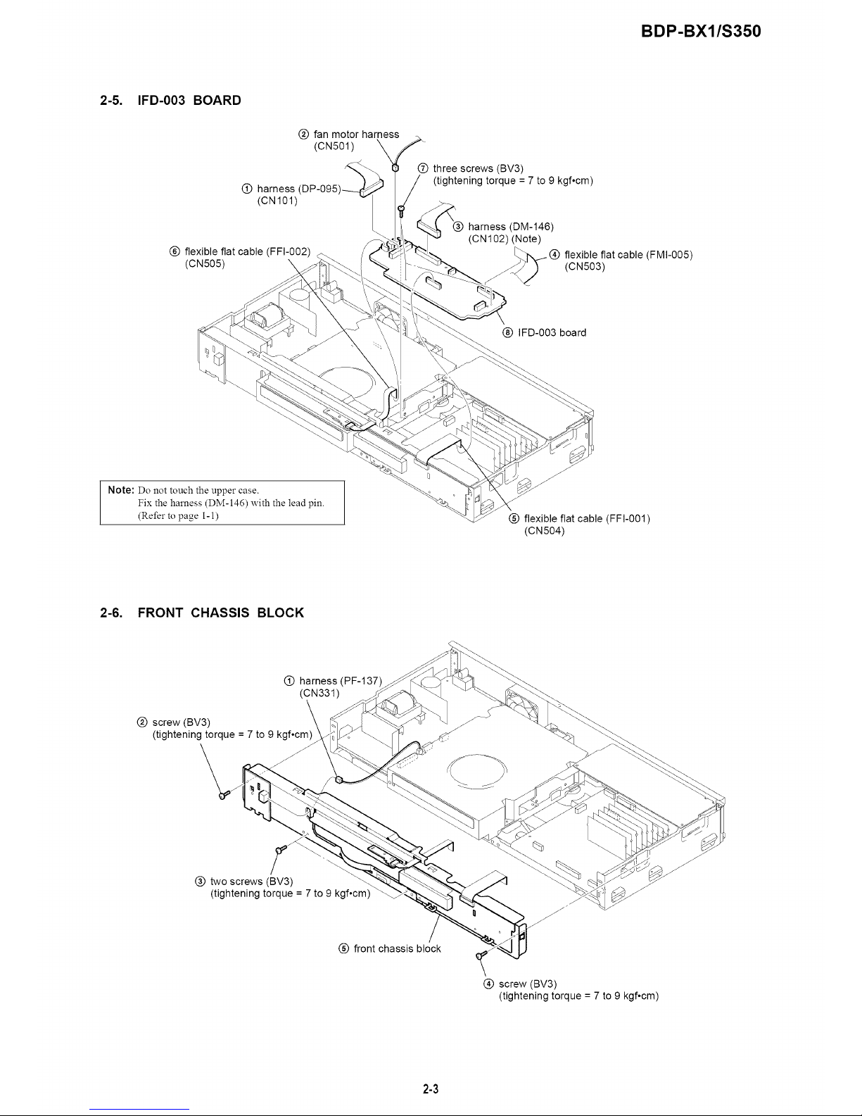
2=5. IFD-003 BOARD
O harness
(CN101)
(_) flexible flat cable (FFI-002)
(CN505) \
@ fan motor harness
(CN501)
O three screws (BV3)
(tightening torque = 7 to 9 kgf,cm)
harness (DM-146)
(ca 102) (Note)
flexible flat cable (FMI-005)
(CN503)
(_) IFD-003 board
Note: Do not touch the upper case.
Fix the harness (DM-146) with the lead pin.
(Refer to page 1-1)
@ flexible flat cable (FFI-001)
(CN504)
2-6. FRONT CHASSIS BLOCK
@ screw (BV3)
(tightening torque = 7 to
O harness (PF-137)
(CN331)
@ two screws (BV3)
(tightening torque = 7 to 9 kgf°cm)
%
(_) front chassis block
f
@ screw (BV3)
(tightening torque = 7 to 9 kgf°cm)
2-3
BDP-BX1/S350
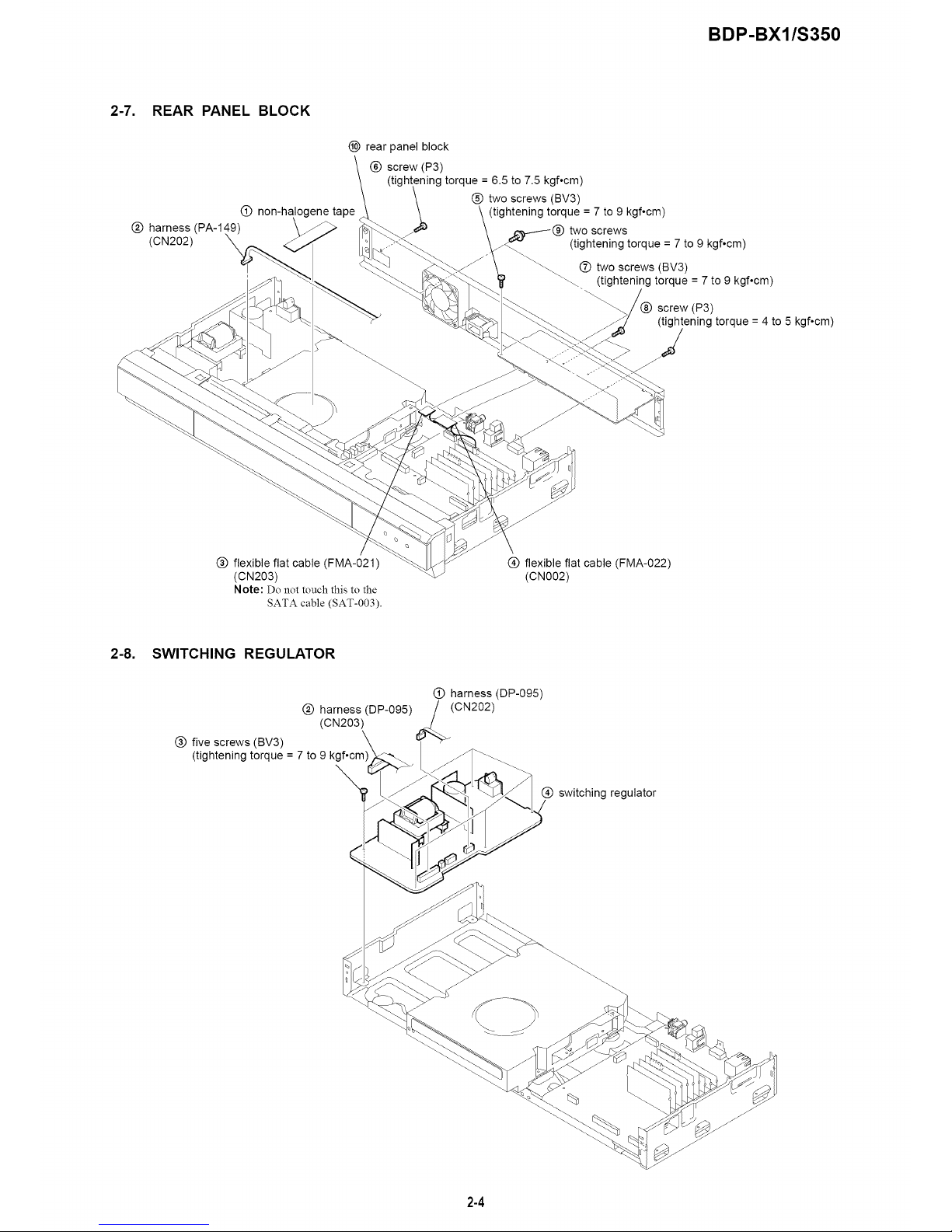
2-7. REAR PANEL BLOCK
@ non-halogene tape
harness (PA-149)
@ (CN202) X
(_ rear panel block
(_) screw (P3)
torque = 6.5 to 7.5 kgf°cm)
@ two screws (BV3)
(tightening torque = 7 to 9 kgf°cm)
__./-_(_) two screws
(tightening torque = 7 to 9 kgf°cm)
(_) two screws (BV3)
(tightening torque = 7 to 9 kgf°cm)
screw (P3)
(tightening torque = 4 to 5 kgf°cm)
2
@ flexible flat cable (FMA-021)
(CN203)
Note: Do not touch this to the
SATA cable (SAT-003).
@ flexible flat cable (FMA-022)
(CN002)
2-8. SWITCHING REGULATOR
@ harness (DP-095)
@ harness (DP-095)/(CN202)
(CN203)
@ five screws (BV3)
(tightening torque = 7 to 9
%
@ switching regulator
%
2-4
BDP-BX1/S350
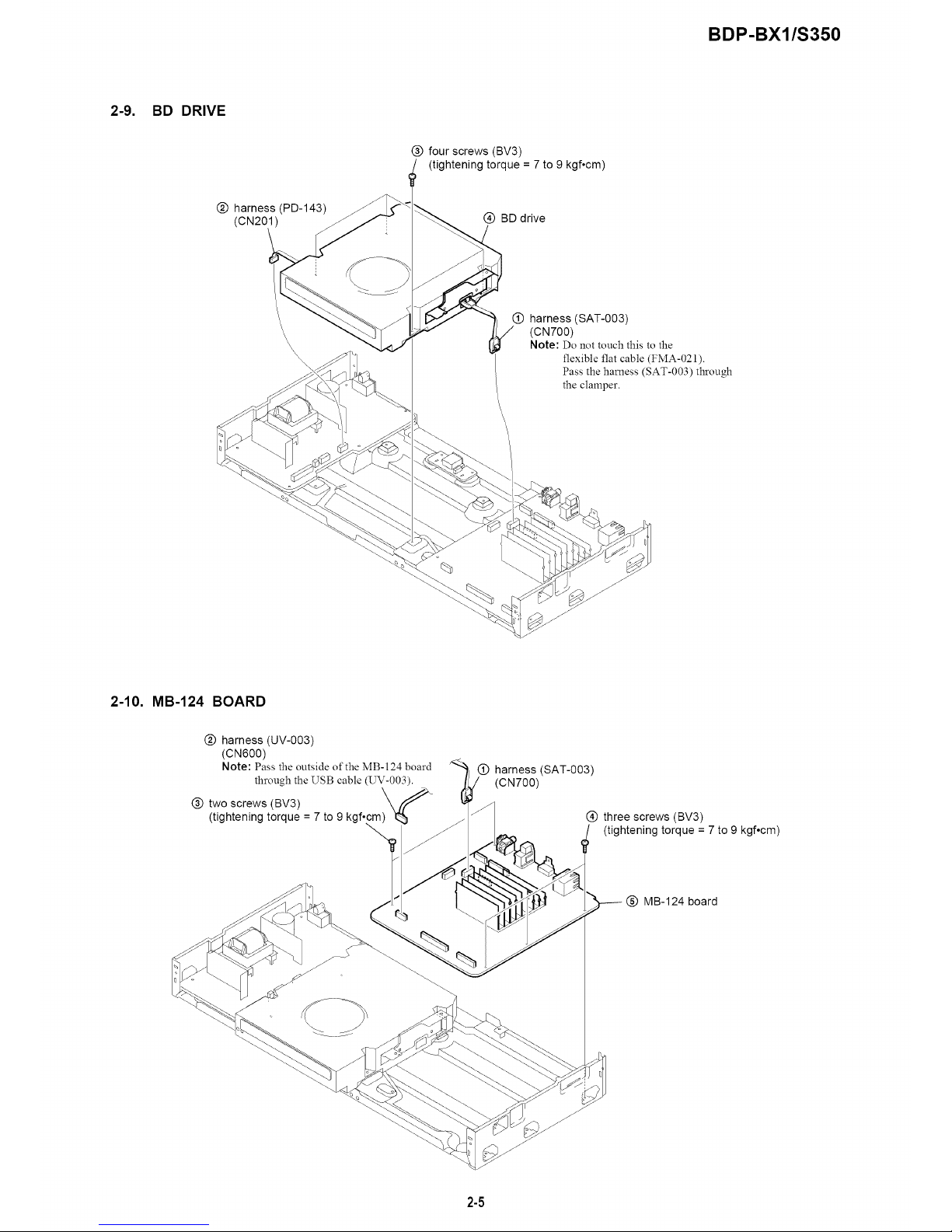
2-9. BD DRIVE
@ harness (PD-143)
(CN201)
@ four screws (BV3)
(tightening torque = 7 to 9 kgf°cm)
@ BD drive
\
\
\
@ harness (SAT-003)
(ca700)
Note: Do not touch this to the
flexible flat cable (FMA-021).
Pass the harness (SAT-003) through
the clamper.
o
%
2-10. MB-124 BOARD
@ harness (UV-003)
(CN600)
Note: Pass the outside of the MB-124 board
through the USB cable (UV-003).
\
@ two screws (BV3)
(tightening torque = 7 to 9 kgf°cm)
@ harness (SAT-003)
(CN700)
@ three screws (BV3)
(tightening torque = 7 to 9 kgf,cm)
(_) MB-124 board
2-5
BDP-BX1/S350
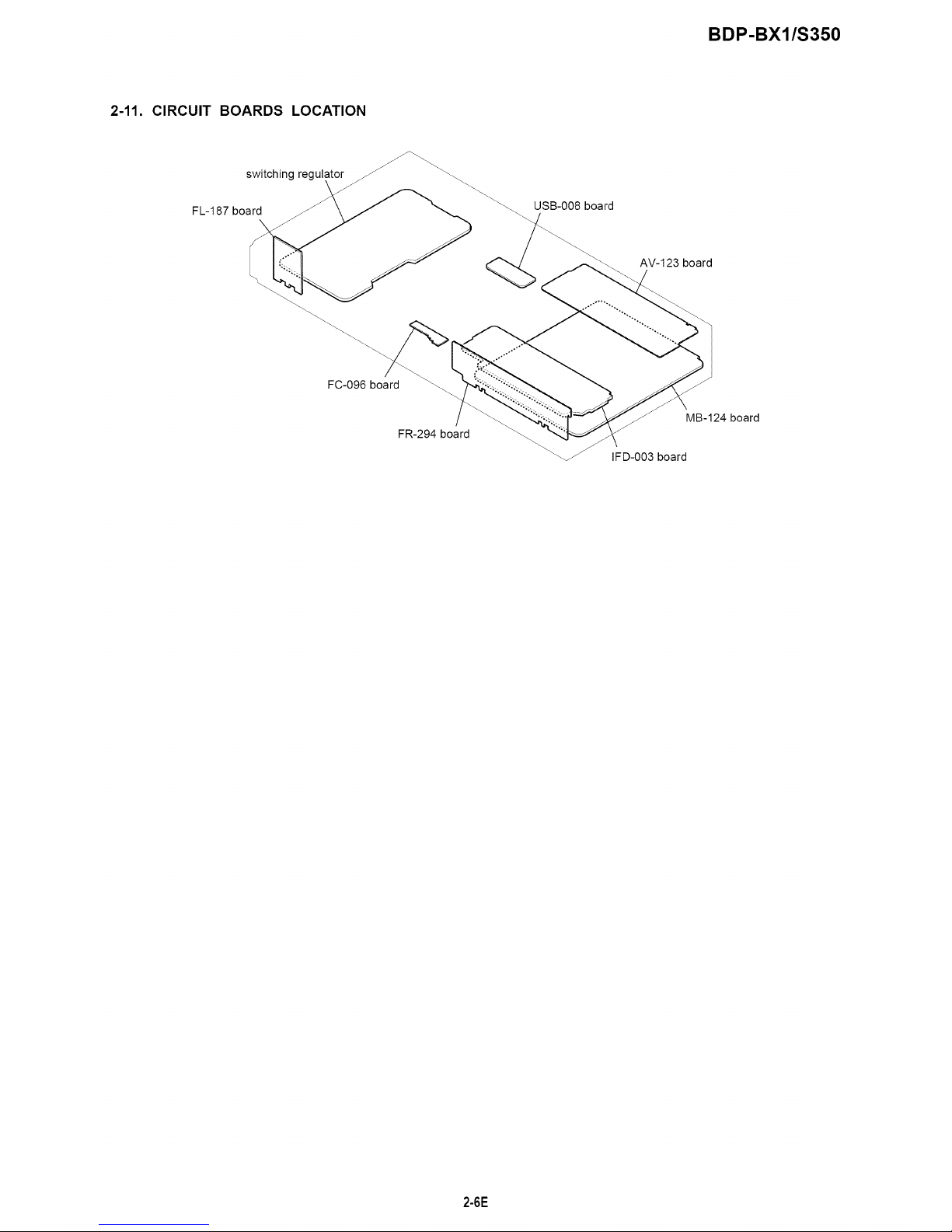
2-11. CIRCUIT BOARDS LOCATION
switching regul
FL-187 board
USB-008 board
AV-123 board
FC-096 board
FR-294 board
MB-124 board
IFD-003 board
2-6E
SECTION 3
BLOCK DIAGRAMS
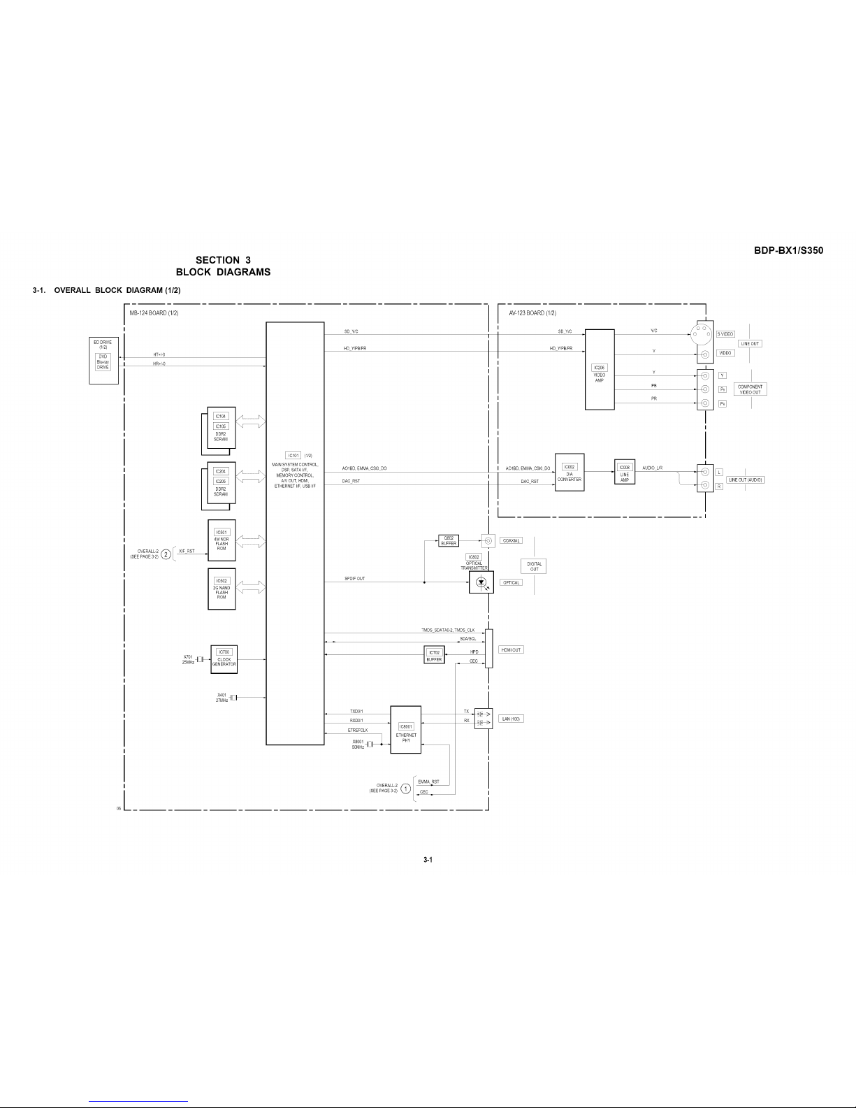
3-1. OVERALL BLOCK DIAGRAM (1/2)
MB-124BOARD(1/2)
05
HT+/-0
HR+/-0
OVERALL-2 (_ XIF RST(SEE PAGE3-2)
X401 4_1 •
27MHz"_
(I/2)
MAINSYSTEMCONTROL,
DSP, SATAI/F,
MEMORY CONTROL,
A/V OUT, HDMI,
ETHERNETI/F, USB I/F
SD Y/C
HD Y/PB/PR
AO1BD, EMMA CSl0 DO
DAC RST
SPDIF OUT
OPTICAL
TRANSMITTER
TMDS SDATA0-2,TMDS CLK
SDA/SCL
BUF_FER i = HPD
= CEC =
TXO0 t I
RXD0/I _1
ETREFCLK /
X8001qlql_ E PHY
50MHz'_' I
EMMA RST
OVERALL-2 _
(SEE PAGE3-2) CEC
TX._
RX
I
I
I
m/
AV-123BOARD(1/2)
SD Y/C
HD Y/PB/PR
VIDEO
AMP
Y/C
V
Y
PB
PR
]
I
AO1BD, EMMA CSI0 DO O_E I
DAC RST _ C R
I
AUDIO L/R
[]
[]
[]
BDP-BX1/S350
COMPONENT
VIDEO OUT
I LINEOUT (AUDIO) ]
I
3-1

BDP-BX1/S350
3-2. OVERALL
USB-008 1I BOARD
_[_ i D÷/D-j
BLOCK DIAGRAM (2/2)
05
MB-124BOARD(2/2)
X600 jrql PCIP CLK USB
33MHz/Ui =
(2/2)
MAINSYSTEM CONTROL
DSP, SATAI/F,
MEMORY CONTROL
AN OUT, HDMI,
ETHERNETI/F, USB I/F
XIFRST
(_I XIF RST
OVERALL-t
(SEE PAGE3-1)
I/ EMMA RST
©hOED.
OVERALL-t
(SEE PAGE3-1)
_lql x6ol
I '-- 30MHz
DAC3.3V
STATt.8V
EMMA SW3.3V
SW3.3V
DDR2 1.8V
PLL1.05V
1V_
+5V POWER(HDMI)
VBUS(USB)
DDL1.0VV
CORE1 05V
SW5VD
1,0303II,0601I
1,0304II,0003I
1,0307II,07011
REGULATOR
1
I
I
I
r iFD-OO3BOARD
I
I IF SDIIIFSDO
I
XIF RST
FR-294BOARD
li -
LED DT,LED CK,
FLD STB
I
I
L SEGl-16
F_R GPD1-1&11,12
-VF
_Q706,707,T701 ]
FR 6V DC/DC
CONVERTER
D
ND701
FLUORESCENT
INDICATOR
I
I
I
I
I
I
I
I
I
I
I
I
I
I
I
I
PCONT2-4 I
I
I
I
I
I
I
_J
X40t d_
32768kHz=Ui -
X402
10MHz ql_
UNSW5.8V
UNSW33V_
UNSW12V _ -1
UNSW58V - Z
SW1.55V : Z
SW33V : Z
DCSW5V _ Z
UNSW3.3V
IF3.3V
FR6V
SUBSYSTEM
CONTROL LED24P
LED DIN
FAN CONT0-2
LEC0
PCONT1-4
I
REGULATOR
FR 6V
IF 33V
PCONT2-4
PCONTll
UNSW12V
UNSW 58V
Ii
I
LED24P
LED DIN
I KEY1-3
I
I
li
I
L
4 D702
I
I
r_ $703-704
$702
C"_o $705
FUNCTIONSWITCH
REMOTECONTROL
RECEIVER
SIRCS
FR 6V
IF 33V
: _ FAN
I BDDRIVE I
[ FC-096BOARD ]
I
I
(BLU-RAYDISC INDICATOR)
AV-123BOARD(2/2)
UNSW12V
DNSW-12V
_ SW5VD
REGULATOR
.1
I
I
F1,F2
DRIVE SW12V
DRIVE SW5V
UNSW12V
UNSW-12V
UNSW6V
UNSW 12V
UNSW58V
TUBE
SWITCHING
REGULATOR
AU5V
33V
-5V
I FL-187
I BOARD
_(AC IN)
3-2
BDP-B×l/S350
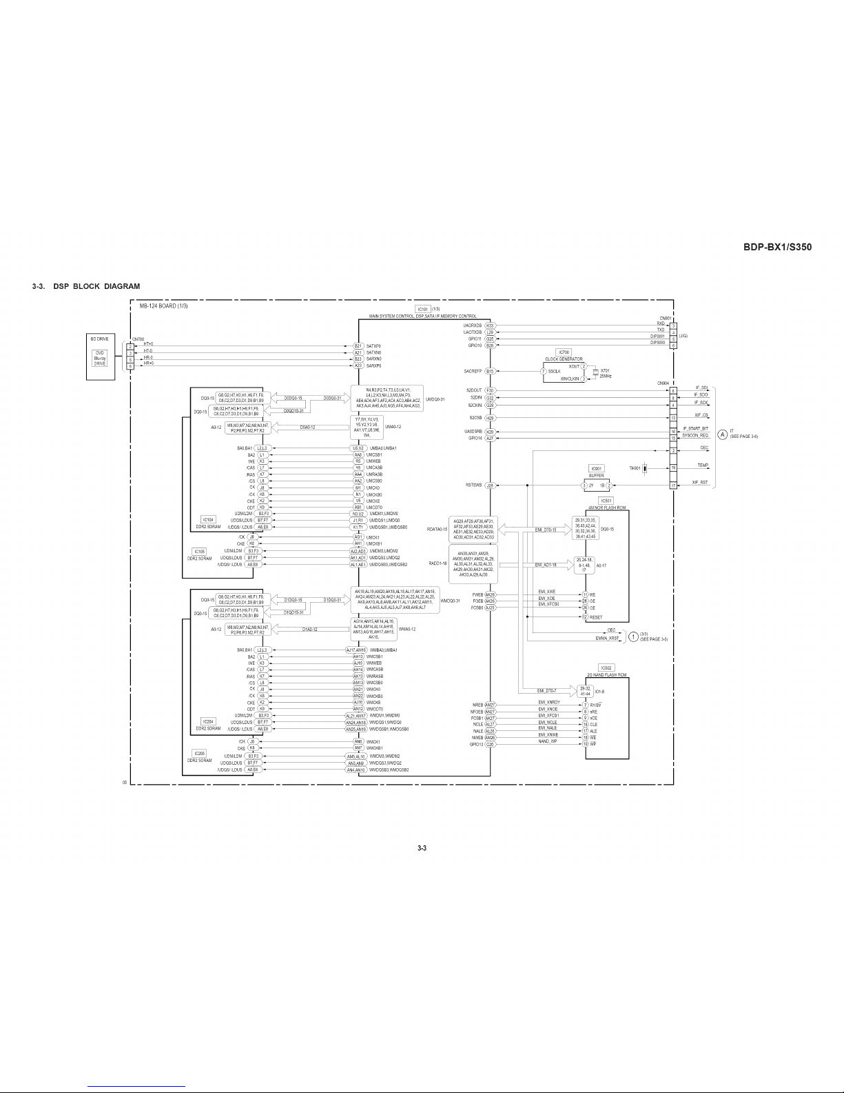
3-3. DSP BLOCK DIAGRAM
r
I MB-124BOARD(1/3)
_ ICN700
I
I
I -
I
I
I
I
I
I
I
I
I
I
I
I
I
I
I
I
I
I
I
f
A0-12 / M8,M3,M7,N2,N8,N3,N7, _/' ...........................................DO,&OJ12.............................................................]
k
P2 P8 P3M2 P7 R2 / _
BA0,BA1 _
BA2_L
/WE(_ )4
/CAS_L ).
/RAS (_ )-
/CS _L )-
CK _ )_
/OKkK ).
CKE_ )-
ODT,.__ )"
UDM/LDM _ B_
A0-12L %E_E_F:[_?...........
BA0,BA1
BA2
/WE {_
/CAS _L
/RAS (_
/CS _L
OK
/CK (K
CKE (>K
ODT _K
UDM/LDM _B:
UDQS/LDUS_
DDR2 SDRAM /UDQS//LDUS
).
).
DDR2SDRAM
)1
).
).
).
).
).
).
/CK _,
CKE _"
UDM/LDM _ -
USQS/LDUS _"
UDQS LDUS _
I_ (I/3)
MAINSYSTEM CONTROL, DSP,SATAFF,MEMORY CONTROL
UAORXDB
UAOTXDB
GRO11
SATXP0 GPIO10
SATXN0
SARXN0
SARXP0
SACREFP _B
R4,R3,P2T4,T3,U3,U4,V1
L4,L2K3 N4,L3,M3,M4,P31
AE4,AD4,AF3 AP2,AC4 AC3,AB4 AC2, UMDQ0-31
AK3 AJ4 AH5:AJ3,AG5:AF4,AH4,AG3
......................................................................:_
Y7,Wt,Y4,V3,
Y5,Y2,Y3,V& UMA0-12
AAI ,V7,U6,W6,
W4,
) UMBA0,UMBA1
UMCSB1
UMWEB
UMCASB
UMRASB
UMCSB0
UMCK0
UMCKB0
UMCKE
UMODT0
S2DOUT
S2DIN
S2CKIN
S2CSB
UAODSRB _
GPIO14
RSTSWB
AG14,AN15,AK14,AL16, WMA0-12
AJ14,AMt4,AL14,AH16,
ANI3,AG16,AHt7,AHt5,
AK15,
_ WMBA0,UMBAI
WMCSB1
WMWEB
WMCASB
WMRASB
WMCSB0
WMCK0
WMCKB0
WMCKE
WMODT0
_ MDMt,WMDM0
WMDQS1,WMDQ0
]t9) WMDQSB1,WMDQSB0
_ WMCK1
WMCKB1
WMDM3,WMDM2
WMDQS3,WMDQ2
WMDQSB3,WMDQSB2
NREB_
NFOEB,
FCSB1,
NCLE,
NALE,
NWEB,
@1013,
CLOCKGENERATOR
XOUT d'_
SSCLK -[ _____X701
X,N/OLK,.d> T 5MHz
I
I
CN90t I
TXD
DIPSW1
DIPSW0 _]
CN904
q
TH901
BUFFER
4M NOR FLASHROM
-18
_ A0-17
)WE
)OE
"( )CE
-__RESET
= CEC = _] _ (3/3)
EMMA XRST J _ (SEEPAGE 3-5)
2G NANDFLASH ROM
EMI XNRDY _( RY/BY
EMI XNOE _{ nRE
EMI XFCS1 _( nCE
EMI NCLE _( CLE
EMI NALE _( ALE
EMI XNWE _{ WE
NAND WP _( )WP
(JIG)
IF SDI
IF SDO
IF SCK
XIF CS
IF START BIT
SYSCON REQ
CEC
TEMP
XlF RST
IT
(SEE PAGE3-6)
3-3
BDP-BX1/S350
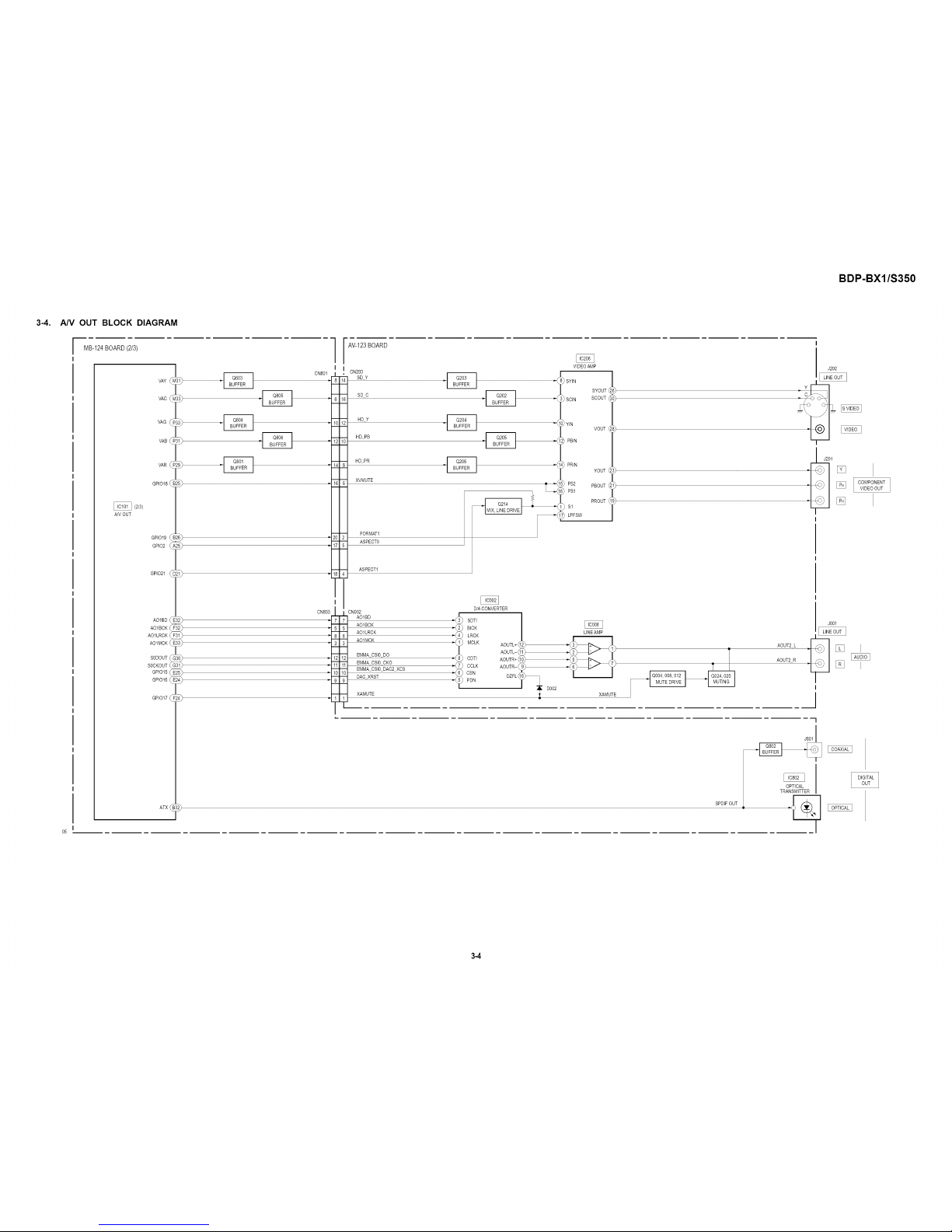
3-4. A/V OUT BLOCK DIAGRAM
[_1 Q004 008, 012
MUlEDR_VEI
MB-124BOARD(2/3)
wG
VAB dF
WR
GPIO18 dE
(2/3)
A/V OUT
GPIO19 dE
GPIO2 d#
GPIO21 _E
AO1BD_E
AO1BCK_
AO1LRCK(_
AO1MCK _E
SODOUT¢c
SOCKOUT_
GPIO15_E.
GPIO16_E
GPIO17
-_5
ATX_
CN801
.iT;
-IZ
_117
CN803
AV-123BOARD
CN203
SD ¥
SD C
HD Y
HD PB
HD PR
XVMUTE
FORMAT1
ASPECT0
ASPECT1
j_CN002
AO1BD
7
-- AO1BCK
5
-- AO1LRCK
8
-- AO1MCK
3
EMMA CSI0 DO
_ EMMA CSI0 CKO
H
-- EMMA CSI0 DAC2 XCS
10
-- DAC XRST
9
T XAMUTE
I
D/ACONVERTER
SDTI
BICK
LRCK
MCLK AOUTL+
AOUTL-
CDTI AOUTR+
CCLK AOUTR-
CSN
DZFL
PDN
D002
VIDEOAMP
( SYIN
SYOUT _
"( SClN SCOUT I
_( )YIN
VOUT
( PBIN
_{ PRIM
YOUT
PS2 PBOUT }
PSl
PROUT
$1
LPFSW
LINEAMP
XAMUTE
SPDIF OUT
AOUT2 L
AOUT2 R
i
I J202
OPTICAL
TRANSMITTER
J201
_} COMPONENT
VIDEO OUT
[]
J001
3-4
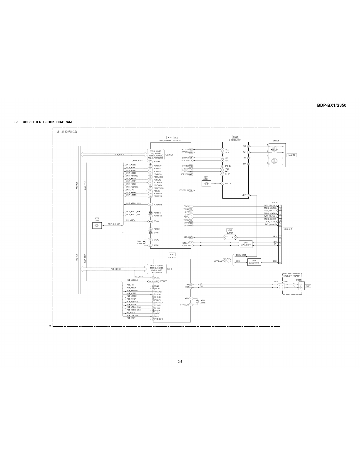
3-5,
USB/ETHER BLOCK DIAGRAM
r'"---
I MB-124BOARD(3/3/
'/
05 I.------------- --
I--
HD_,_ETHERNET I/F,USB WP
PCIAD0-31
_CICBEB1
]poICBEB2
: PCIIRDYB
PCITRDYB
pcISTOPB
)CIDEVSELB
PCIPAR
_OISERRB
PCIREQB2
PCIGNTBI
PCIGNTB2
GPIO30
) PCICLKI
GPIO9
ISYSXO
X401
27MHz SYSXI
EI_XD0 (
EI_XD1 I
ETMDC (
ETMDIO (
ETCRS(
ETRXDO(
ETRXDI/
ETRXER
I
ETHERNET PHY
RXP(
RXN
TXP
TXN
CN702
TMDSS
79_7674-7270,67,
66,64[62,59,58 56,
USB HOST
ADO-B1 !
EMMA XRST
I
OEC
CN6OQ
________ _ .--.-.--J
I CN30_ }
,CN362
I........ --J
3-5

BDP-BX1/S350
3-6. IT BLOCK DIAGRAM
DSP
(SEE PAGE3-3)
IF SDI
IF SDO
IF SCK
XlF CS
XIF RST
TEMP
IFD-003BOARD
CN503
q
IF START BIT
=SYSCON REQ
CEC
IFCON FLASH f
i, WRTTER it
05
X401
32.768kHz
X402
10MHz '--(
CN402
MODE
IF RXD
IFTXD
RESET
UNSW58V
_) P FAIL
VCC OUT
UNSW33V
_.4_ RESET
VCC OUT1_
,( IF SDI
IF SDO
IF SCK
" { XIF CS
SYSCON RST
TEMP
STARTBIT
SYSCON REQ
CEC IN
CEC OUT
XCOUT
XCIN
SUB SYSTEM
CONTROL
FLD SO0,
FLD SCK,
FLD STB,
FLD PCONT
LED DIMMER
LED1
KEY1
KEY2
KEY3'
XOUT
XIN
SIRCS IN
_( MODE
RXD1
_( TXD1
LED0
PFIAL
FAN CONTO
/RESET
FAN CONT1
FAN CONT2
FAN DET1
)4
14
CN504
FR-294BOARD
CNT01
LED DT
LED CK
FLD STB
FLDRIVER
_{ DIN
SG1-16_4
_{ CLK
"{ STB GP1-8,11,12 _.42-3_
SEG1-16
32,31} GPDI-8J%12 _
NDT01
FLUORESCENT
INDICATOR
TUBE
_ Dc/QcO_707_T7CTIER_ FR 6V
FLD PCONT
LED DIN
LED24P
D7O2
KEY1
KEY2
KEY3
$703,704
_) <_ FUNCTION SWITCH
$702
_} (_ FUNCTION SWITCH
$705
_} o_ FUNCTIONSWITCH
SIRCS
REMOTECONTROL
RECEIVER
FAN CONTO
FAN CONT1
FAN CONT2
FAN
CONTROL
CN505
-E
CN501
FC-096BOARD I
CN301
D30t
, (BLU-RAY DISC INDICATOR) I
l
M501
(FAN)
3-6
BDP-BX1/S350
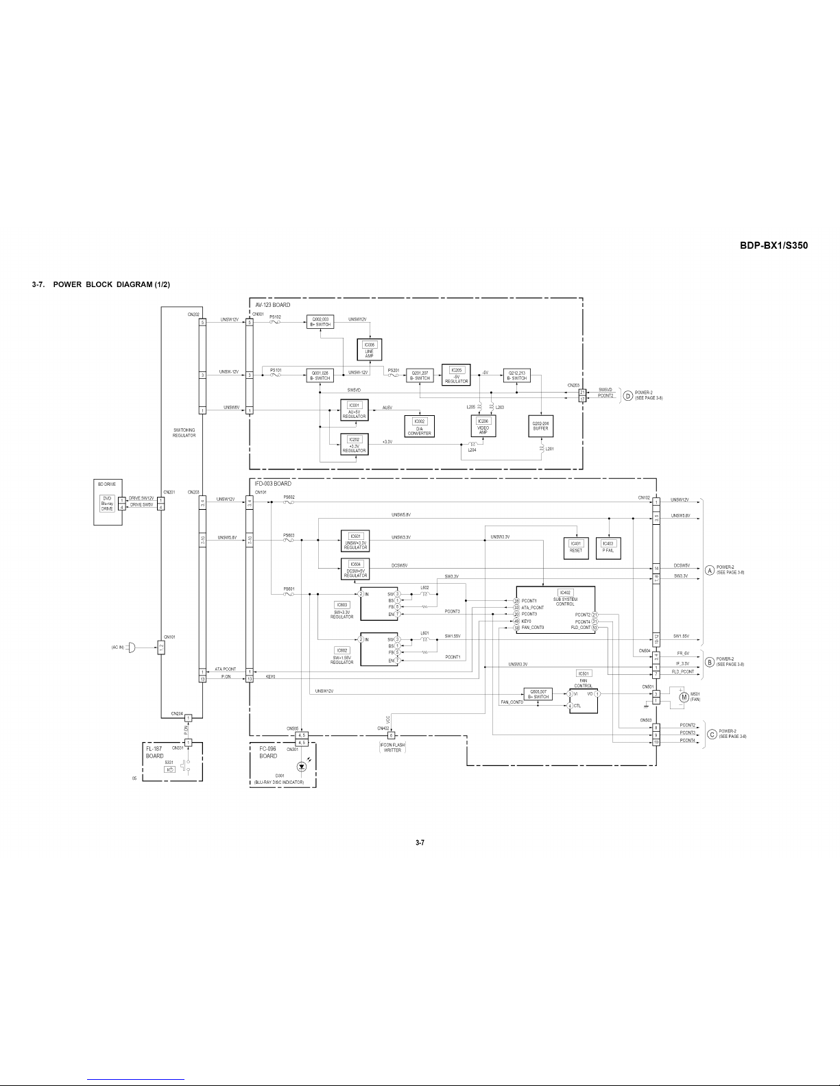
3-7. POWER BLOCK DIAGRAM (1/2)
_ RIVESW12V E
DRIVESW5V
(ACIN)
CN202
SWITCHING
REGULATOR
CN201 CN203
CN1Ol
CN204
i
o
05 [
3--
I
AV-123BOARD
UNSW12V
UNSW-12V
UNSW6V
CNO01
/ PSI01 _ / I PS2Ol _ _ 5V
swsvo_/__
AO_V ,_o__o3
T
_.33v ,c°_T_-._ _-_
I L204 _ L201
CN2°3E_:
I
SW5VD i @ POWER_2
PCONT2 (SEE PAGE 3-8)
/
UNSW12V
UNSW5.8V
ATA PCONT
P.ON
IFD-003BOARD
CN1Ol
PS6O2
UNSW58V
PS603
PS60t
KEY0
CN5O5
FC-096 CN3
BOARD
D301
(BLU-RAYDISC INDICATOR)
I REGULATORI
_I'_
SW+3 3V
REGULATOR
.IINSW+1.55V
REGULATOR
UNSW12V
UNSW33V
DCSW5V
SW3.3V
PCONT3
>o
CN40
IFCONFLASH
WRITTER /
L60I
SW1.55V
PCONT1
'-I
I
[
UNSW33V
I
ATA PCONT
PC_T3
KEY0
FAN CONT0
UNSW33V
FAN
CONTROL
FANCONT:_
CN102
CN5Ol
9
CN503
_i-
UNSW12V ."
UNSW5.8V
DCSW5V
SW33V
SW155V
FR 6V
IF 33V
FLD PCONT
M501
(FAN)
7 PCONT2
t PCONT3
PCONT4
POWER-2
(SEE PAGE3-8)
POWER-2
(SEE PAGE3-8)
POWER-2
(SEE PAGE3-8)
3-7
 Loading...