

Sony HDR-CX500, HDR-CX500E, HDR-CX505VE, HDR-CX500VE, HDR-CX520 Service Manual
...
SERVICE MANUAL
Sony EMCS Co.
LEVEL 2
Link
SERVICE NOTE
MODEL INFORMATION TABLE
SPECIFICATIONS
FRAME SCHEMATIC DIAGRAM
BLOCK DIAGRAMS
DISASSEMBLY
PRINTED WIRING BOARDS
REPAIR PARTS LIST
SCHEMATIC DIAGRAMS
Link
Revision History
Revision History
HDR-CX500/CX500E/CX500V/CX500VE/CX505VE/
CX520/CX520E/CX520V/CX520VE_L2
HDR-CX500/CX500E/CX500V/CX500VE/CX505VE
/CX520/CX520E/CX520V/CX520VE
Ver. 1.1 2009.12
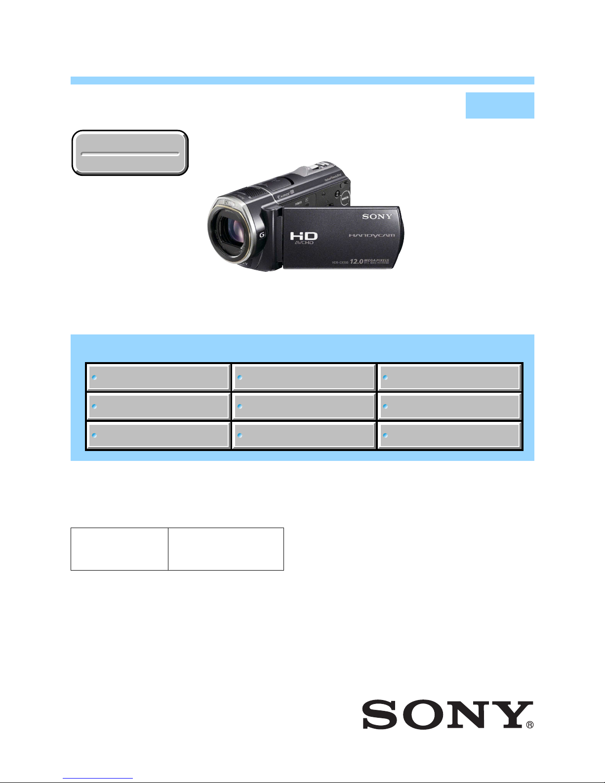
DIGITAL HD VIDEO CAMERA RECORDER
The components identified by
mark 0 or dotted line with
mark 0 are critical for safety.
Replace only with part number specified.
Les composants identifiés par une
marque 0 sont critiques pour la
sécurité.
Ne les remplacer que par une pièce
portant le numéro spécifié.
2009L0800-1
© 2009.12
Published by Tokai TEC9-852-714-32
RMT-835
Photo: HDR-CX500
US Model
Canadian Model
AEP Model
UK Model
North European Model
E Model
Australian Model
Hong Kong Model
Chinese Model
Korea Model
Tourist Model
Japanese Model
• Precaution on Replacing the VC-575 Board
• Precaution on Replacing the CABINET (BOTTOM) ASSY
• Precaution on Replacing the MM-083 Board
— 2 —
ENGLISH JAPANESE
ENGLISH JAPANESE
HDR-CX500/CX500E/CX500V/CX500VE/CX505VE/
CX520/CX520E/CX520V/CX520VE_L2
SPECIFICATIONS
These specifications are extracted from instruction manual of
HDR-CX500E/CX500VE/CX505VE/CX520E/CX520VE.
System
Signal format: PAL color, CCIR standards HDTV
1080/50i specification
Movie recording format:
Video: HD: MPEG-4 AVC/H.264 AVCHD
format compatible
SD: MPEG-2 PS
Audio: Dolby Digital 2ch/5.1ch
Dolby Digital 5.1 Creator
Photo file format
: DCF Ver.2.0 Compatible
: Exif Ver.2.21 Compatible
: MPF Baseline Compatible
Recording media (Movie/Photo)
Internal memory
HDR-CX500E/CX500VE/CX505VE: 32GB
HDR-CX520E/CX520VE: 64GB
“Memory Stick PRO Duo” media
When measuring media capacity, 1 GB equals
1 billion bytes, a portion of which is used for
system management and/or application files.
The capacity that a user can use is below.
HDR-CX500E:
approximately 31.5 GB
HDR-CX500VE/CX505VE:
approximately 30.7 GB
HDR-CX520E:
approximately 63.5 GB
HDR-CX520VE:
approximately 62.7 GB
Image device: 6.3 mm (1/2.88 type) CMOS sensor
Recording pixels (photo, 4:3):
Max. 12.0 mega (4 000 × 3 000) pixels*
Gross: Approx. 6 631 000 pixels
Effective (movie, 16:9):
Approx. 4 150 000 pixels**
Effective (photo, 16:9):
Approx. 4 500 000 pixels
Effective (photo, 4:3):
Approx. 6 000 000 pixels
Lens: Sony G lens
12 × (Optical), 24 × , 150 × (Digital)
Filter diameter: 37 mm (1 1/2 in.)
F1.8 ~ 3.4
Focal length:
f=5.5 ~ 66.0 mm (7/32 ~ 2 5/8 in.)
When converted to a 35 mm still camera
For movies: 43 ~ 516 mm (1 3/4 ~ 20 3/8
in.)** (16:9)
For photos: 38 ~ 456 mm (1 1/2 ~ 18 in.) (4:3)
Color temperature: [AUTO], [ONE PUSH],
[INDOOR] (3 200 K), [OUTDOOR]
(5 800 K)
Minimum illumination
11 lx (lux) (in default setting, shutter speed 1/50
second)
3 lx (lux) (LOW LUX is set to [ON], shutter speed
1/25 second)
0 lx (lux) (NIGHTSHOT is set to [ON])
*
The unique pixel array of Sony's ClearVid
and the image processing system
(BIONZ) allow still image resolution
equivalent to the sizes described.
** [ STEADYSHOT] is set to
[STANDARD] or [OFF].
Input/Output connectors
A/V Remote Connector: Component/video and
audio output jack
HDMI OUT jack: HDMI mini connector
USB jack: mini-AB
LCD screen
Picture: 7.5 cm (3.0 type, aspect ratio 16:9)
Total number of pixels: 230 400 (960 × 240)
General
Power requirements: DC 6.8 V/7.2 V (battery
pack) DC 8.4 V (AC Adaptor)
Average power consumption: During camera
recording, using LCD screen at normal
brightness: HD: 3.4 W SD: 2.7 W
Operating temperature: 0 °C to 40 °C (32 °F to
104 °F)
Storage temperature: –20 °C to + 60 °C (-4 °F to
+140 °F)
Dimensions (approx.):
62 × 65 × 125 mm (2 1/2 × 2 5/8 × 5 in.)
(w/h/d) including the projecting parts
62 × 65 × 133 mm (2 1/2 × 2 5/8 × 5 3/8 in.)
(w/h/d) including the projecting parts, and
the supplied rechargeable battery pack attached
Mass (approx.)
HDR-CX500E/CX520E:
360 g (13 oz) main unit only
440 g (16 oz) including the supplied
rechargeable battery pack
HDR-CX500VE/CX505VE/CX520VE:
370 g (13 oz) main unit only
450 g (1 lb) including the supplied
rechargeable battery pack
AC Adaptor AC-L200C/AC-L200D
Power requirements: AC 100 V - 240 V,
50 Hz/60 Hz
Current consumption: 0.35 A - 0.18 A
Power consumption: 18 W
Output voltage: DC 8.4 V*
Operating temperature: 0 °C to 40 °C (32 °F to
104 °F)
Storage temperature: –20 °C to + 60 °C (–4 °F to
+140 °F)
Dimensions (approx.): 48 × 29 × 81 mm (1 15/16
× 1 3/16 × 3 1/4 in.) (w/h/d) excluding the
projecting parts
Mass (approx.): 170 g (6.0 oz) excluding the
power cord (mains lead)
* See the label on the AC Adaptor for other
specifications.
Rechargeable battery pack NP-FH60
Maximum output voltage: DC 8.4 V
Output voltage: DC 7.2 V
Maximum charge voltage: DC 8.4 V
Maximum charge current: 2.12 A
Capacity: 7.2 Wh (1 000 mAh)
Type: Li-ion
Design and specifications of your camcorder and
accessories are subject to change without notice.
•Manufactured under license from Dolby
Laboratories.

— 3 —
ENGLISH JAPANESE
ENGLISH JAPANESE
HDR-CX500/CX500E/CX500V/CX500VE/CX505VE/
CX520/CX520E/CX520V/CX520VE_L2
SPECIFICATIONS
These specifications are extracted from instruction manual of
HDR-CX500/CX500V/CX520/CX520V.
System
Signal format: NTSC color, EIA standards HDTV
1080/60i specification
Movie recording format:
Video: HD: MPEG-4 AVC/H.264 AVCHD
format compatible
SD: MPEG-2 PS
Audio: Dolby Digital 2ch/5.1ch
Dolby Digital 5.1 Creator
Photo file format
: DCF Ver.2.0 Compatible
: Exif Ver.2.21 Compatible
: MPF Baseline Compatible
Recording media (Movie/Photo)
Internal memory
HDR-CX500/CX500V: 32GB
HDR-CX520/CX520V: 64GB
“Memory Stick PRO Duo” media
When measuring media capacity, 1 GB equals
1 billion bytes, a portion of which is used for
system management and/or application files.
The capacity that a user can use is below.
HDR-CX500:
approximately 31.5 GB
HDR-CX500V:
approximately 30.7 GB
HDR-CX520:
approximately 63.5 GB
HDR-CX520V:
approximately 62.7 GB
Image device: 6.3 mm (1/2.88 type) CMOS sensor
Recording pixels (photo, 4:3):
Max. 12.0 mega (4 000 × 3 000) pixels*
Gross: Approx. 6 631 000 pixels
Effective (movie, 16:9):
Approx. 4 150 000 pixels**
Effective (photo, 16:9):
Approx. 4 500 000 pixels
Effective (photo, 4:3):
Approx. 6 000 000 pixels
Lens: Sony G lens
12 × (Optical), 24 × , 150 × (Digital)
Filter diameter: 37 mm (1 1/2 in.)
F1.8 ~ 3.4
Focal length:
f=5.5 ~ 66.0 mm (7/32 ~ 2 5/8 in.)
When converted to a 35 mm still camera
For movies: 43 ~ 516 mm (1 3/4 ~ 20 3/8
in.)** (16:9)
For photos: 38 ~ 456 mm (1 1/2 ~ 18 in.) (4:3)
Color temperature: [AUTO], [ONE PUSH],
[INDOOR] (3 200 K), [OUTDOOR]
(5 800 K)
Minimum illumination
11 lx (lux) (in default setting, shutter speed 1/60
second)
3 lx (lux) (LOW LUX is set to [ON], shutter speed
1/30 second)
0 lx (lux) (NIGHTSHOT is set to [ON])
*
The unique pixel array of Sony's ClearVid
and the image processing system
(BIONZ) allow still image resolution
equivalent to the sizes described.
** [ STEADYSHOT] is set to
[STANDARD] or [OFF].
Input/Output connectors
A/V Remote Connector: Component/video and
audio output jack
HDMI OUT jack: HDMI mini connector
USB jack: mini-AB
LCD screen
Picture: 7.5 cm (3.0 type, aspect ratio 16:9)
Total number of pixels: 230 400 (960 × 240)
General
Power requirements: DC 6.8 V/7.2 V (battery
pack) DC 8.4 V (AC Adaptor)
Average power consumption: During camera
recording, using LCD screen at normal
brightness: HD: 3.6 W SD: 2.7 W
Operating temperature: 0 °C to 40 °C (32 °F to
104 °F)
Storage temperature: –20 °C to + 60 °C (-4 °F to
+140 °F)
Dimensions (approx.):
62 × 65 × 125 mm (2 1/2 × 2 5/8 × 5 in.)
(w/h/d) including the projecting parts
62 × 65 × 133 mm (2 1/2 × 2 5/8 × 5 3/8 in.)
(w/h/d) including the projecting parts, and
the supplied rechargeable battery pack attached
Mass (approx.)
HDR-CX500/CX520:
360 g (13 oz) main unit only
440 g (16 oz) including the supplied
rechargeable battery pack
HDR-CX500V/CX520V:
370 g (13 oz) main unit only
450 g (1 lb) including the supplied
rechargeable battery pack
AC Adaptor AC-L200C/AC-L200D
Power requirements: AC 100 V - 240 V,
50 Hz/60 Hz
Current consumption: 0.35 A - 0.18 A
Power consumption: 18 W
Output voltage: DC 8.4 V*
Operating temperature: 0 °C to 40 °C (32 °F to
104 °F)
Storage temperature: –20 °C to + 60 °C (–4 °F to
+140 °F)
Dimensions (approx.): 48 × 29 × 81 mm (1 15/16
× 1 3/16 × 3 1/4 in.) (w/h/d) excluding the
projecting parts
Mass (approx.): 170 g (6.0 oz) excluding the
power cord (mains lead)
* See the label on the AC Adaptor for other
specifications.
Rechargeable battery pack NP-FH60
Maximum output voltage: DC 8.4 V
Output voltage: DC 7.2 V
Maximum charge voltage: DC 8.4 V
Maximum charge current: 2.12 A
Capacity: 7.2 Wh (1 000 mAh)
Type: Li-ion
Design and specifications of your camcorder and
accessories are subject to change without notice.
•Manufactured under license from Dolby
Laboratories.
— 4 —
ENGLISH JAPANESE
ENGLISH JAPANESE
HDR-CX500/CX500E/CX500V/CX500VE/CX505VE/
CX520/CX520E/CX520V/CX520VE_L2
概略仕様
システム
信号方式:NTSCカラー、EIA標準方式
ビデオ記録方式
映像:HD画質:MPEG-4AVC/H.264
AVCHD規格準拠
SD画質:MPEG-2PS
音声:DolbyDigital2ch/5.1ch
ドルビーデジタル5.1クリエーター搭載
静止画ファイルフォーマット
:DCFVer2.0準拠
:ExifVer2.21準拠
:MPFBaseline準拠
記録メディア(動画・静止画)
内蔵メモリー
HDR-CX500V:32GB
HDR-CX520V:64GB
メモリースティックPROデュオ
容量は、1GBを10億バイトで計算した場合の数
値です。また管理用ファイル、アプリケーショ
ンファイルなどを含むため、実際に使用できる
容量は減少します。ご使用いただけるユーザー
容量は、次のとおりです。
HDR-CX500V約30.7GB
HDR-CX520V約62.7GB
撮像素子:6.3mm(1/2.88型)CMOSセンサー
記録画素数:静止画時最大1200万画素相当
*
(4000×3000)(4:3時)
総画素数:約663万画素
動画時有効画素数(16:9):約415万画素
**
静止画時有効画素数(16:9):約450万画素
静止画時有効画素数(4:3):約600万画素
ズームレンズ:ソニーGレンズ
12倍(光学)、24倍、150倍(デジタル)
フィルター径:37mm
F1.8〜3.4
f=5.5〜66.0mm
35mmカメラ換算では
動画撮影時:
43〜516mm(16:9)
**
静止画撮影時:
38〜456mm(4:3)
色温度切り換え:[オート]、[ワンプッシュ]、[屋内]
(3200K)、[屋外](5800K)
最低被写体照度:
11lx(ルクス)(お買い上げ時、[シャッタース
ピード]1/60秒)
3lx(ルクス)(LOWLUX時、[シャッタースピー
ド]1/30秒)
0lx(ルクス)(NIGHTSHOT時)
*
ソニー独自のクリアビッド画素配列と画像処
理システムBIONZにより、静止画は表記の記
録サイズを実現しています。
**
[手ブレ補正機能]が[スタンダード]、または
[切]のとき。
入/出力端子
A/Vリモート端子:コンポーネント、映像音声出力兼用端子
HDMI端子:HDMIミニコネクタ
USB端子:mini-AB
液晶画面
画面サイズ:7.5cm(3.0型、アスペクト比16:9)
総ドット数:230400ドット
横960×縦240
電源部、その他
電源電圧:バッテリー端子入力6.8V/7.2V
DC端子入力8.4V
消費電力:液晶画面の明るさ標準:
HD:3.6W
SD:2.7W
動作温度:0℃〜40℃
保存温度:−20℃〜+60℃
外形寸法:62×65×125mm
(突起部を含む)(幅×高さ×奥行き)
62×65×133mm
(突起部を含む、付属バッテリー装着状態)
(幅×高さ×奥行き)
本体質量:
約370g(本体のみ)
撮影時総質量:
約450g(付属バッテリー含む。)
ACアダプターAC-L200C/AC-L200D
電源:AC100V-240V、50Hz/60Hz
消費電力:18W
定格出力:DC8.4V
*
動作温度:0℃〜40℃
保存温度:−20℃〜+60℃
外形寸法:約48×29×81mm(最大突起部をのぞく)
(幅×高さ×奥行き)
質量:約170g(本体のみ)
*
その他の仕様についてはACアダプターのラベルを
ご覧ください。
リチャージャブルバッテリーパック
NP-FH60
最大電圧:DC8.4V
公称電圧:DC7.2V
容量:7.2Wh(1000mAh)
使用電池:Li-ion
本機やアクセサリーの仕様および外観は、改良のため
予告なく変更することがありますが、ご了承ください。
• ドルビーラボラトリーズからの実施権に基づき
製造されています。
— 5 —
HDR-CX500/CX500E/CX500V/CX500VE/CX505VE/
CX520/CX520E/CX520V/CX520VE_L2
Model information table
•Abbreviation
AUS: Australian model
CH : Chinese model
CND : Canadian model
HK : Hong Kong model
J: Japanese model
JE : Tourist model
KR : Korea model
NE : North European model
Model
Destination
Color system
GPS function
HDR-CX500
E, KR
NTSC
Not built in
32GB
HDR-CX500E
NE, E,
CH, HK, JE
PA L
Not built in
32GB
HDR-CX500V
US, CND, J
NTSC
Built in
32GB
HDR-CX500VE
AUS
PA L
Built in
32GB
HDR-CX505VE
AEP, UK
PA L
Built in
32GBInternal memory
HDR-CX520E
NE, E,
CH, JE
PA L
HDR-CX520
E
NTSC
Model
Destination
Color system
Not built in Not built in
HDR-CX520VE
AEP, UK, AUS
PA L
HDR-CX520V
US, CND, J
NTSC
Built in Built inGPS function
64GB 64GB 64GB 64GBInternal memory
Input/Output Input/Output Input/Output Input/Output Output onlyUSB function
××ΟΟΟ
FP-1021 flexible board
Input/Output Input/Output Input/Output Input/OutputUSB function
××ΟΟ
FP-1021 flexible board
— 6 —
ENGLISH JAPANESE
ENGLISH JAPANESE
HDR-CX500/CX500E/CX500V/CX500VE/CX505VE/
CX520/CX520E/CX520V/CX520VE_L2
SAFETY-RELATED COMPONENT WARNING!!
COMPONENTS IDENTIFIED BY MARK 0 OR DOTTED LINE WITH
MARK 0 ON THE SCHEMATIC DIAGRAMS AND IN THE PARTS
LIST ARE CRITICAL TO SAFE OPERATION. REPLACE THESE
COMPONENTS WITH SONY PARTS WHOSE PART NUMBERS
APPEAR AS SHOWN IN THIS MANUAL OR IN SUPPLEMENTS
PUBLISHED BY SONY.
1. Check the area of your repair for unsoldered or poorly-soldered
connections. Check the entire board surface for solder splashes
and bridges.
2. Check the interboard wiring to ensure that no wires are
"pinched" or contact high-wattage resistors.
3. Look for unauthorized replacement parts, particularly
transistors, that were installed during a previous repair. Point
them out to the customer and recommend their replacement.
4. Look for parts which, through functioning, show obvious signs
of deterioration. Point them out to the customer and
recommend their replacement.
5. Check the B+ voltage to see it is at the values specified.
6. Flexible Circuit Board Repairing
•Keep the temperature of the soldering iron around 270˚C
during repairing.
• Do not touch the soldering iron on the same conductor of the
circuit board (within 3 times).
• Be careful not to apply force on the conductor when soldering
or unsoldering.
SAFETY CHECK-OUT
After correcting the original service problem, perform the following
safety checks before releasing the set to the customer.
ATTENTION AU COMPOSANT AYANT RAPPORT
À LA SÉCURITÉ!
LES COMPOSANTS IDENTIFÉS PAR UNE MARQUE 0 SUR LES
DIAGRAMMES SCHÉMATIQUES ET LA LISTE DES PIÈCES SONT
CRITIQUES POUR LA SÉCURITÉ DE FONCTIONNEMENT. NE
REMPLACER CES COMPOSANTS QUE PAR DES PIÈSES SONY
DONT LES NUMÉROS SONT DONNÉS DANS CE MANUEL OU
DANS LES SUPPÉMENTS PUBLIÉS PAR SONY.
Unleaded solder
Boards requiring use of unleaded solder are printed with the leadfree mark (LF) indicating the solder contains no lead.
(Caution: Some printed circuit boards may not come printed with
the lead free mark due to their particular size.)
: LEAD FREE MARK
Unleaded solder has the following characteristics.
• Unleaded solder melts at a temperature about 40°C higher than
ordinary solder.
Ordinary soldering irons can be used but the iron tip has to be
applied to the solder joint for a slightly longer time.
Soldering irons using a temperature regulator should be set to
about 350°C.
Caution: The printed pattern (copper foil) may peel away if the
heated tip is applied for too long, so be careful!
• Strong viscosity
Unleaded solder is more viscous (sticky, less prone to flow) than
ordinary solder so use caution not to let solder bridges occur such
as on IC pins, etc.
•Usable with ordinary solder
It is best to use only unleaded solder but unleaded solder may
also be added to ordinary solder.
CAUTION
Danger of explosion if battery is incorrectly replaced.
Replace only with the same or equivalent type.
Dispose of used batteries according to the instructions.
— 7 —
ENGLISH JAPANESE
ENGLISH JAPANESE
HDR-CX500/CX500E/CX500V/CX500VE/CX505VE/
CX520/CX520E/CX520V/CX520VE_L2
1. 注意事項をお守りください。
サービスのとき特に注意を要する個所については,
キャビネット,シャーシ,部品などにラベルや捺印で
注意事項を表示しています。これらの注意書き及び取
扱説明書等の注意事項を必ずお守り下さい。
2. 指定部品のご使用を
セットの部品は難燃性や耐電圧など安全上の特性を
持ったものとなっています。従って交換部品は,使用
されていたものと同じ特性の部品を使用して下さい。
特に回路図,部品表に0 印で指定されている安全上重要
な部品は必ず指定のものをご使用下さい。
3. 部品の取付けや配線の引きまわしはもとどおりに
安全上,チューブやテープなどの絶縁材料を使用した
り,プリント基板から浮かして取付けた部品がありま
す。また内部配線は引きまわしやクランパによって発
熱部品や高圧部品に接近しないよう配慮されています
ので,これらは必ずもとどおりにして下さい。
4. サービス後は安全点検を
サービスのために取外したネジ,部品,配線がもとど
おりになっているか,またサービスした個所の周辺を
劣化させてしまったところがないかなどを点検し,安
全性が確保されていることを確認して下さい。
5. チップ部品交換時の注意
• 取外した部品は再使用しないで下さい。
• タンタルコンデンサのマイナス側は熱に弱いため交
換時は注意して下さい。
サービス,点検時には次のことにご注意下さい。
注意
電池の交換は,正しく行わないと破裂する恐れがあり
ます。電池を交換する場合には必ず同じ型名の電池
又は同等品と交換してください。
使用済の電池は,取扱指示に従って処分してください。
6. フレキシブルプリント基板の取扱いについて
• コテ先温度を270℃前後にして行なって下さい。
• 同一パターンに何度もコテ先を当てないで下さい。
(3回以内)
• パターンに力が加わらないよう注意して下さい。
7. 無鉛半田について
無鉛半田を使用している基板には,無鉛(LeadFree)を意
味するレッドフリーマークがプリントされています。
(注意:基板サイズによっては,無鉛半田を使用して
いてもレッドフリーマークがプリントされて
いないものがあります)
:レッドフリーマーク
無鉛半田には,以下の特性があります。
• 融点が従来の半田よりも約40℃高い。
従来の半田こてをそのまま使用することは可能です
が,少し長めにこてを当てる必要があります。
温度調節機能のついた半田こてを使用する場合,約
350℃に設定して下さい。
注意: 半田こてを長く当てすぎると,基板のパター
ン(銅箔)がはがれてしまうことがあります
ので,注意して下さい。
• 粘性が強い
従来の半田よりも粘性が強いため,IC端子などが半田
ブリッジしないように注意して下さい。
• 従来の半田と混ぜて使用可能
無鉛半田には無鉛半田を追加するのが最適ですが,
従来の半田を追加しても構いません。

1-1
ENGLISH JAPANESE
ENGLISH JAPANESE
HDR-CX500/CX500E/CX500V/CX500VE/CX505VE/
CX520/CX520E/CX520V/CX520VE_L2
1. SERVICE NOTE
1-1. POWER SUPPLY DURING REPAIRS
In this unit, about 10 seconds after power is supplied to the battery terminal using the regulated power supply (8.4V), the power is shut off so
that the unit cannot operate.
These following method is available to prevent this.
Method:
Use the AC power adaptor (AC-L200C/L200D).
1-2. PRECAUTION ON REPLACING THE VC-575 BOARD
DESTINATION DATA
When you replace to the repairing board, the written destination data of repairing board also might be changed to original setting.
Start the Adjust Manual in the Adjust Station and execute the [DESTINATION DATA WRITE].
DESTINATION DATA WRITE
After the board replacement, the error of the built-in recording media may be displayed. in this case, execute the [DESTINATION DATA
WRITE] then the error will be cleared. If it is not cleared with [DESTINATION DATA WRITE], format the built-in recording media.
USB SERIAL SAVE
When you replace to the repairing board, get the data from the former one.
Start the Adjust Manual in the Adjust Station and perform “USB SERIAL SAVE” to get the data.
USB SERIAL No.
The set is shipped with a unique ID (USB Serial No.) written in it.
This ID has not been written in a new board for service, and therefore it must be entered after the board replacement.
Start the Adjust Manual in the Adjust Station and execute the “USB serial No. input”.
The changed portions from
Ver. 1.0 are shown in blue.
Ver. 1.1 2009.12
1-2
ENGLISH JAPANESE
ENGLISH JAPANESE
HDR-CX500/CX500E/CX500V/CX500VE/CX505VE/
CX520/CX520E/CX520V/CX520VE_L2
1-3. SELF-DIAGNOSIS FUNCTION
1-3-1. Self-diagnosis Function
When problems occur while the unit is operating, the self-diagnosis
function starts working, and displays on the LCD screen what to
do. This function consists of two display; self-diagnosis display and
service mode display.
Details of the self-diagnosis functions are provided in the Instruction
manual.
1-3-2. Self-diagnosis Display
When problems occur while the unit is operating, the counter of the
LCD screen shows a 4-digit display consisting of an alphabet and
numbers, which blinks at 3.2 Hz. This 5-character display indicates
the “repaired by:”, “block” in which the problem occurred, and
“detailed code” of the problem.
1 1
3 1C
Repaired by:
Refer to “1-3-3. Self-diagnosis Code Table”.
Indicates the appropriate
step to be taken.
E.g.
31 ....Reload the tape.
32 ....Turn on power again.
Block
Detailed Code
Blinks at 3.2Hz
C : Corrected by customer
H : Corrected by dealer
E : Corrected by service
engineer
LCD screen
C : 3 1 : 1 1
1-3-3. Self-diagnosis Code Table
C
C
C
C
C
E
E
E
Block
Function
04
06
13
13
32
20
61
61
Detailed
Code
00
00
01
02
60
00
10
11
Symptom/State
Non-standard battery is used.
The battery pack temperature is high.
“Memory Stick Duo” is unformatted.
“Memory Stick Duo” is broken.
Access error
Difficult to adjust focus
(Cannot initialize focus)
Flash memory data are rewritten.
Zoom operations fault
(Cannot initialize zoom lens.)
The abnormalities in initialization of
the focus lens and the abnormalities in
initialization of the zoom lens occurred
simultaneously.
Self-diagnosis Code
Repaired by:
Correction
Use the InfoLITHIUM battery.
Change the battery pack or place it in a cool place.
Format the “Memory Stick Duo”.
Insert a new “Memory Stick Duo”.
Remove the power source. Reconnect it again and operate your
camcorder again
Retry turn the power on by the power switch. If it does not
recover, check the focus MR sensor of lens block (pin e;, ea of
CN1010 on the VC-575 board). If it is OK, check the focus
motor drive IC (IC5201 on the VC-575 board).
Make flash memory data correct value. (Note 1)
Inspect the lens block zoom MR sensor (pin ef, eg of CN1010
on the VC-575 board) when zooming is performed when the
zoom lever is operated, or the zoom motor drive circuit (IC5201
on the VC-575 board) when zooming is not performed.
Check both C: 32: 60 and E: 61: 10 of the self-diagnosis code.
Note 1 : Start the Adjust Manual in the Adjust Station and refer to the “Destination data write”.
1-3
ENGLISH JAPANESE
ENGLISH JAPANESE
HDR-CX500/CX500E/CX500V/CX500VE/CX505VE/
CX520/CX520E/CX520V/CX520VE_L2
E
E
E
E
E
E
E
E
E
E
E
E
E
E
E
E
Block
Function
62
62
6 2
6 2
6 2
6 2
6 2
6 2
6 2
91
92
94
94
94
95
96
Detailed
Code
00
01
02
03
04
10
11
12
20
01
01
00
01
02
00
00
Symptom/State
Handshake correction function does not
work well. (With PITCH angular
velocity sensor output stopped.)
Handshake correction function does not
work well. (With YAW angular velocity
sensor output stopped.)
Abnormality of IC for steadyshot.
IC for steadyshot and micro controller
communication abnormality among.
Image vibration correction during
handshake function does not work.
Shift lens initializing failure.
Shift lens overheating (Pitch)
Shift lens overheating (Yaw)
Abnormality of thermistor.
Abnormality when flash is being charged.
Battery current value goes over the
max discharge current
Fault of writing or erasing the
flash memory
Internal flash memory fault
BGM data error
GPS hardware error
Map area mount error
Self-diagnosis Code
Repaired by:
Correction
Inspect PITCH angular velocity sensors (SE6601 on the MM-083
board) peripheral circuits.
Inspect YAW angular velocity sensors (SE6601 on the MM-083
board) peripheral circuits.
Refer to [1-4-1. E : 62 : 02 (Abnormality of IC for Steadyshot)
Occurred].
Inspect the steadyshot circuit (IC5501 on the VC-575 board).
Inspect the image vibraton angular velocity sensors
(SE9001 on the ST-217 board) peripheral circuits.
Replacement of lens block. If an error occurs again, replace the
VC-575 board. (Note 2)
Refer to [1-4-2. E : 62 : 11 (Shift Lens Overheating (Pitch))
Occurred].
Refer to [1-4-3. E : 62 : 12 (Shift Lens Overheating (Yaw))
Occurred].
Refer to [1-4-4. E : 62 : 20 (Abnormality of Thermistor)
Occurred].
Checking of flash unit or replacement of flash unit.
Check the remaining battery power because this symptom maybe
depended on the remaining battery level, and confirm whether or
not the symptom is occured after replacing the battery.
If the symptom is still occured, overhaul inspection is needed.
Check each output of DC/DC converter (IC4701) on VC-575
board connected to CK-217 board with FP-1127 board, and
connect DC/Batt harness (the minimum connection to periphery)
to VC-575 board.
Inspect the flash memory (IC8101 on the VC-575 board).
Inspect the flash memory (IC8101 on the VC-575 board).
Inspect the flash memory (IC8101 on the VC-575 board). If it is
OK, check the CPU (IC7501 on the VC-557 board).
CX500V/CX500VE/CX505VE/CX520V/CX520VE
Check whether the flexible board of the GPS module is broken,
and check whether it is inserted imperfectly. If there is no
problem the flexible board, inspect or replacement of the GPS
module.
CX500V/CX500VE/CX505VE/CX520V/CX520VE
Inspect or replacement of the MM-083 board.
Note 2 : When the lens block was replaced, start the Adjust Manual in the Adjust Station and execute the necessary adjustment
items.
After the adjustment, make sure with the STEADYSHOT turned ON that the steadyshot functions appropriately in the
handheld operation.
1-4
ENGLISH JAPANESE
ENGLISH JAPANESE
HDR-CX500/CX500E/CX500V/CX500VE/CX505VE/
CX520/CX520E/CX520V/CX520VE_L2
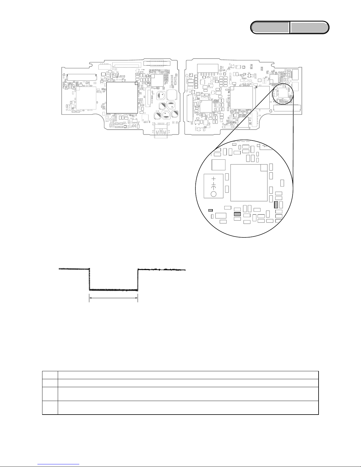
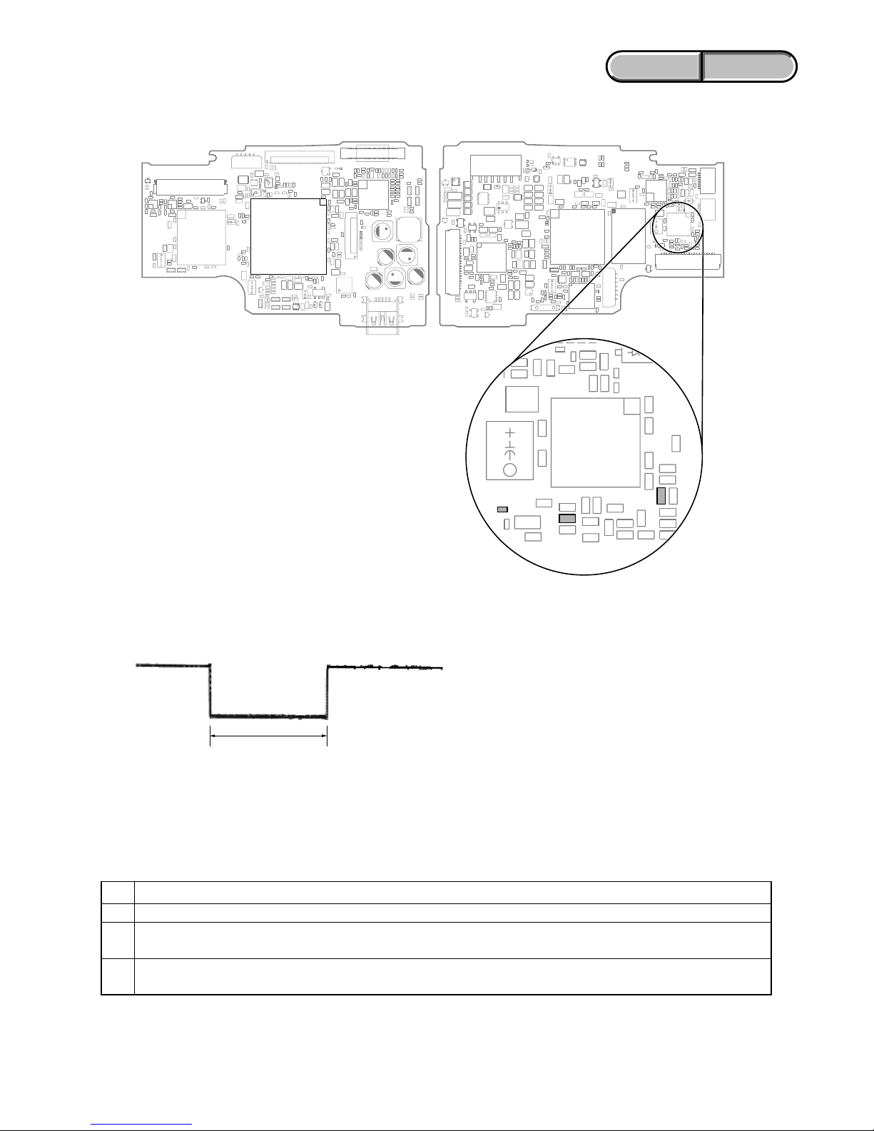
*R5653
*R5653:
No mount (Short land)
IC5501
R5524
R5527
VC-575 BOARD (SIDE B)VC-575 BOARD (SIDE A)
IC7501
1-4. METHOD OF COPING WITH SHIFT LENS ERROR
about 330 msec
Fig. 2
Change in output voltage of R5653 land on the VC-575 board
Note: The length of low section will vary a little depending on the
conditions.
1-4-1. E : 62 : 02 [Abnormality of IC for Steadyshot] Occurred
Order Procedure
1Turn the power OFF.
2
While measuring with an oscilloscope the output voltage of R5653 land in the periphery of IC5501 on the VC-575 board, turn
the power ON to check that the output voltage immediately after the power on change as shown in Fig. 2.
3
If the output voltage change as shown in Fig. 2, replace the lens block (Note). If it does not change as shown in Fig. 2, inspect
the camera control circuit (IC7501 of VC-575 board) periphery.
Note: When the lens block was replaced, start the Adjust Manual in the Adjust Station and execute the necessary adjustment
items.
After the adjustment, make sure with the STEADYSHOT turned ON that the steadyshot functions appropriately in the
handheld operation.
Fig. 1
Measurement points on the VC-575 board
1-5
ENGLISH JAPANESE
ENGLISH JAPANESE
HDR-CX500/CX500E/CX500V/CX500VE/CX505VE/
CX520/CX520E/CX520V/CX520VE_L2
1-4-2. E : 62 : 11 [Shift Lens Overheating (Pitch)] Occurred
Connect by the SeusEX and perform the following process.
Order Block Page Address Data Procedure
111807430 01 Write the data. (After it starts, set it before caution is displayed.)
2118EF654 01 Write the data.
3118EF655 F0 Write the data.
4118EF658 01 Write the data. (Note 1)
5118EF658 00 Write the data.
6118EF654 00 Write the data.
7118EF655 10 Write the data.
8118EF658 01 Write the data. (Note 1)
9118EF658 00 Write the data.
10 11 80 7430 00 Write the data.
11
Check if the shift lens moves while setting the order 2 to 9. If the shift lens does not move,
replace the lens block (Note 2). When the shift lens moved, proceed to the order 12.
12
While setting the order 2 to 9, measure with an oscilloscope the output voltage of R5527 in the
periphery of IC5501 on the VC-575 board to check the output voltage varies.
13
If the output voltage does not vary, replace the lens block (Note 2). When the output voltage
varied, proceed to the order 14.
14 Turn the power OFF.
While measuring with an oscilloscope the output voltage of R5653 land in the periphery of
15 IC5501 on the VC-575 board, turn the power ON to check that the output voltage immediately
after the power on change as shown in Fig. 2.
If the output voltage change as shown in Fig. 2, replace the lens block (Note 2). If it does not
16 change as shown in Fig. 2, inspect the camera control circuit (IC7501 of VC-575 board)
periphery.
Note 1: Finish this operation within 10 seconds. If it is likely to take more than 10 seconds, set block: 11, page: 8E, address:
F658, data: 00, and then retry.
Note 2: When the lens block was replaced, start the Adjust Manual in the Adjust Station and execute the necessary adjustment
items.
After the adjustment, make sure with the STEADYSHOT turned ON that the steadyshot functions appropriately in the
handheld operation.
1-6
ENGLISH JAPANESE
ENGLISH JAPANESE
HDR-CX500/CX500E/CX500V/CX500VE/CX505VE/
CX520/CX520E/CX520V/CX520VE_L2
1-4-3. E : 62 : 12 [Shift Lens Overheating (Yaw)] Occurred
Connect by the SeusEX and perform the following process.
Order Block Page Address Data Procedure
111807430 01 Write the data. (After it starts, set it before caution is displayed.)
2118EF656 01 Write the data.
3118EF657 F0 Write the data.
4118EF659 01 Write the data. (Note 1)
5118EF659 00 Write the data.
6118EF656 00 Write the data.
7118EF657 10 Write the data.
8118EF659 01 Write the data. (Note 1)
9118EF659 00 Write the data.
10 11 80 7430 00 Write the data.
11
Check if the shift lens moves while setting the order 2 to 9. If the shift lens does not move,
replace the lens block (Note 2). When the shift lens moved, proceed to the order 12.
12
While setting the order 2 to 9, measure with an oscilloscope the output voltage of R5524 in the
periphery of IC5501 on the VC-575 board to check the output voltage varies.
13
If the output voltage does not vary, replace the lens block (Note 2). When the output voltage
varied, proceed to the order 14.
14 Turn the power OFF.
While measuring with an oscilloscope the output voltage of R5653 land in the periphery of
15 IC5501 on the VC-575 board, turn the power ON to check that the output voltage immediately
after the power on change as shown in Fig. 2.
If the output voltage change as shown in Fig. 2, replace the lens block (Note 2). If it does not
16 change as shown in Fig. 2, inspect the camera control circuit (IC7501 of VC-575 board)
periphery.
Note 1: Finish this operation within 10 seconds. If it is likely to take more than 10 seconds, set block: 11, page: 8E, address:
F659, data: 00, and then retry.
Note 2: When the lens block was replaced, start the Adjust Manual in the Adjust Station and execute the necessary adjustment
items.
After the adjustment, make sure with the STEADYSHOT turned ON that the steadyshot functions appropriately in the
handheld operation.
1-4-4. E : 62 : 20 [Abnormality of Thermistor] Occurred
Order Procedure
1Turn the power ON.
2 Confirm the connections of flexible flat cables and connectors between the lens block and VC-575 board.
3
In case of no malfunction of connections, replace the lens block with new one. (Note) When the error has occurred in spite of the
lens replacement, replace VC-575 board with new one.
Note: When the lens block was replaced, start the Adjust Manual in the Adjust Station and execute the necessary adjustment
items.
After the adjustment, make sure with the STEADYSHOT turned ON that the steadyshot functions appropriately in the
handheld operation.
1-7
ENGLISH JAPANESE
ENGLISH JAPANESE
HDR-CX500/CX500E/CX500V/CX500VE/CX505VE/
CX520/CX520E/CX520V/CX520VE_L2
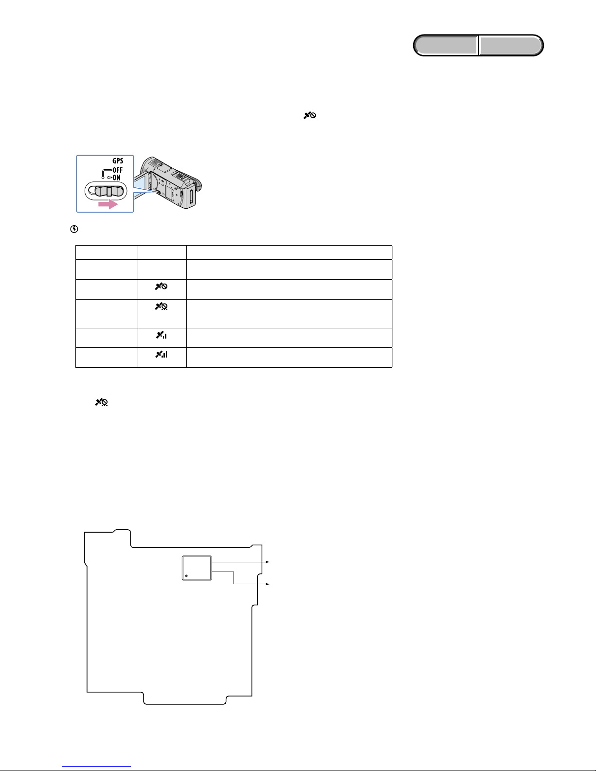
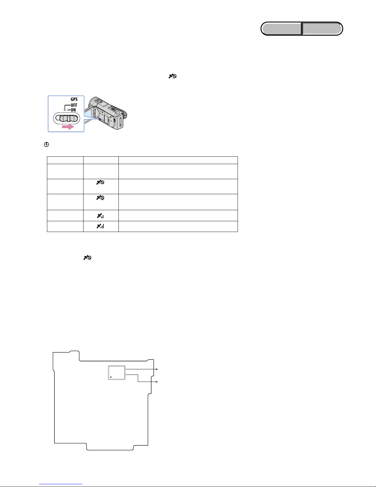
1-5. GPS RECEIVING CHECK (CX500V/CX500VE/CX505VE/CX520V/CX520VE)
After a part of set was replaced or after the set was assembled, check the reception of GPS signal.
How to check the GPS function
Bring your camcorder to an open area, and set the GPS switch to ON ( appears on the LCD
screen). Your camcorder starts trying to triangulate. When your camcorder triangulates
successfully, it will record the location information at the time movies and photos were recorded.
• The indicator changes according to the strength of GPS signal reception.
Triangulating status GPS indicators GPS reception status
Function off No indicator
The GPS switch is set to OFF, or the GPS receiver is not
functioning normally.
Difficult
Your camcorder cannot find a GPS signal, therefore, it cannot
triangulate. Use your camcorder in an open area.
Processing
Your camcorder is confirming the GPS signal, and will be able
to acquire location information soon. Wait until your camcorder
completes the triangulation.
Triangulating
Your camcorder is receiving a GPS signal, and can acquire location
information.
Triangulating
Your camcorder is receiving a strong GPS signal, and can acquire
location information.
• It may take from several seconds to several minutes to acquire the location information when you use the
GPS for the first time or use it again after long intervals.
• You may not be able to acquire location information depending on the strength of GPS reception.
• When is displayed and it takes a while to triangulate, set the GPS switch to OFF, then set to ON again.
Notes
1-6. PRECAUTION ON REPLACING THE MM-083 BOARD
Do not factory check MM-083 board in which Map Data is installed (CX500V/CX500VE/CX505VE/CX520V/CX520VE).
The map data is erased when the factory check is done.
Angular Velocity Sensor
When you replace to the reparing board, write down the sensitivity displayed on the angular velocity sensor (SE6601).
Start the Adjust Manual in the Adjust Station and execute the “GYRO sensor sensitivity adj”.
Note: The sensor sensitivity of SE6601 of MM-083 board is written only repair parts.
SE6601
PPP
YYY
MM-083 BOARD (SIDE B)
PPP:
PITCH sensor sensitivity
t
G
1
YYY:
YAW sensor sensitivity
t
G
2

1-8
ENGLISH JAPANESE
ENGLISH JAPANESE
HDR-CX500/CX500E/CX500V/CX500VE/CX505VE/
CX520/CX520E/CX520V/CX520VE_L2
1. SERVICE NOTE
1-1. 修理時の電源供給について
本機では,安定化電源(8.4Vdc)からバッテリ端子に電源を供給した場合,約10 秒後にシャットオフし,動作しなくなります。
これを避けるため,下記の方法を用いてください。
方法:
ACアダプタ(AC-L200C/L200D)を使用する。
1-2. VC-575基板交換時の注意
仕向けデータ
補修用基板と交換する時,補修用基板に書かれている仕向けデータは元の設定と違っている場合があります。
AdjustStationからAdjustManualを起動させて「DESTINATIONDATAWRITE」を実行させてください。
仕向けデータ設定
補修用基板交換後、電源を入れると内蔵記録メディアエラーが表示される場合がありますが、「DESTINATION DATA
WRITE」を実行させると消えます。「DESTINATIONDATA WRITE」実行しても消えない場合は、内蔵記録メディアを
フォーマットしてください。
USBシリアルセーブ
補修用基板と交換する時,交換前の基板よりUSBシリアルNo.を取得してください。
データの取得はAdjustStationからAdjustManualを起動させて「USBSERIALSAVE」を実行させてください。
USBシリアルNo.
セットは,1台毎に異なる固有のID(USBSerialNo.)を書き込んだ後,出荷されています。
新品の補修用基板には,このIDが書き込まれていないので,基板交換後にIDを入力する必要があります。
AdjustStationからAdjustManualを起動させて「USBserialNo.input」を実行させてください。
Ver. 1.1 2009.12
Ver.1.0からの変更部分は
青色で記載されています。

1-9
ENGLISH JAPANESE
ENGLISH JAPANESE
HDR-CX500/CX500E/CX500V/CX500VE/CX505VE/
CX520/CX520E/CX520V/CX520VE_L2
症状/状態
標準以外のバッテリを使用している
バッテリが高温になっている
フォーマットしていないメモリー
ステックデュオを入れた
メモリーステックデュオが壊
れている
アクセスエラー
フォーカスが合いにくい
(フォーカスの初期化ができない)
フラッシュメモリが書き換えられている
ズーム動作の異常(ズームレンズの
初期化ができない)
フォーカス,ズーム異常
C
C
C
C
C
E
E
E
ブロック
機能
04
06
13
13
32
20
61
61
詳細
コード
00
00
01
02
60
00
10
11
自己診断コード
1-3. 自己診断機能
1-3-1. 自己診断機能について
本機の動作に不具合が生じたとき,自己診断機能が働き,
LCD画面に,どう処置したらよいか判断できる表示を行い
ます。「自己診断表示」と「サービスモード表示」の2つの表
示があります。自己診断機能については取扱説明書にも掲載
されています。
1-3-2. 自己診断表示
本機の動作に不具合が生じたとき,LCD画面のカウンタ表示
部分がアルファベットと数字の4桁表示になり,3.2Hzで点
滅します。この5 文字の表示によって対応者分類および不具
合の生じたブロックの分類,不具合の詳細コードを示しま
す。
1 1
3 1C
対応者分類
「1-3 -3 . 自己診断コード表」
を参照
対応方法の違いにより分類
例 31 ・・・テープを入れ直す
32 ・・・電源を入れ直す
ブロック分類
詳細コード
3.2Hz点滅
C :お客さま自身で対応
H :販売店で対応
E :サービスエンジニア
で対応
LCD画面
C : 3 1 : 1 1
1-3-3. 自己診断コード表
対
応
者
注意1:AdjustStationからAdjustManualを起動させて,「Destinationdatawrite」を参照してください。
対応/方法
インフォリチウムバッテリを使用する。
バッテリを交換するか,バッテリを涼しいところに置く。
メモリーステックデュオをフォーマットする。
新しいメモリーステックデュオに交換する。
電源を外し,再度入れ直してから操作する。
操作スイッチの電源を入れ直す。
復帰しない場合,レンズブロックのフォーカスMRセンサ
(VC-575基板CN1010e;,eaピン)を点検する。異常なけ
ればフォーカスモータ駆動回路(VC-575基板IC5201)を点
検する。
フラッシュメモリのデータを元の値に戻す。(注意1)
ズームレバーを操作したときにズーム動作をすれば,レン
ズブロックのズームMRセンサ(
VC-575基板
CN1010ef,eg
ピン)を点検する。ズーム動作をしなければズームモータ
駆動回路(
VC-575
基板IC5201)を点検する。
自己診断コードC:32:60とE:61:10の両方を点検する。
1-10
ENGLISH JAPANESE
ENGLISH JAPANESE
HDR-CX500/CX500E/CX500V/CX500VE/CX505VE/
CX520/CX520E/CX520V/CX520VE_L2
自己診断コード
ブロック
機能
62
62
62
62
62
62
62
62
62
91
92
94
94
94
95
96
詳細
コード
00
01
02
03
04
10
11
12
20
01
01
00
01
02
00
00
症状/状態
手振れ補正が効きにくい(PITCH
角速度センサ出力張り付き)
手振れ補正が効きにくい(YAW角
速度センサ出力張り付き)
手振れ補正用ICの異常
手振れ補正用ICとマイクロコント
ローラーとの通信異常
Active手振れ補正時の画ゆれが補正
できない(角速度センサ出力張り付き)
シフトレンズ初期化異常
シフトレンズオーバーヒート
(PITCH)
シフトレンズオーバーヒート
(YAW)
サーミスタの異常
フラッシュの充電異常
(バッテリーの)電流値が最大放電電
流を超えた
フラッシュメモリの書込み/消去動
作不良
フラッシュメモリ内部異常
BGMデータ異常
GPSハードウェア異常
MAPエリアマウント異常
対応/方法
PITCH角速度センサ(MM-083基板SE6601)周辺回路を点
検する。
YAW角速度センサ(MM-083基板SE6601)周辺回路を点
検する。
「1-4-1.E:62:02(手振れ補正用ICの異常)が出た場合」を参照。
手振れ補正回路(VC-575基板IC5501)を点検する。
画ゆれ検出角速度センサ(ST-217基板SE9001)周辺回路を点
検する。
レンズブロックを交換する。エラーが再度発生する場合
は,VC-575基板を交換する。(注意2)
「1-4-2.E:62:11(シフトレンズオーバーヒート(PITCH))が出
た場合」を参照。
「1-4-3.E:62:12(シフトレンズオーバーヒート(YAW))が出
た場合」を参照。
「1-4-4.E:6 2:20(サーミスタの異常)が出た場合」を参照。
フラッシュユニットの点検または交換をする。
バッテリ残量に依存する場合があるので,バッテリ残量
を確認する。次にバッテリを交換して症状が出るか確認す
る。バッテリを交換しても症状が出る場合は,エラー発生
後に電源が切れてしまうため,分解して確認する,VC575基板にCK-217基板をFP-1127(VC-CK)フレキシブル基
板で接続し,DC/バッテリハーネスをVC-575基板に接続し
た状態(最小限の接続)でDC/DCコンバータ(VC-575基板
IC4701)の各チャンネル出力を確認する。
フラッシュメモリ(VC-575基板IC8101)を点検する。
フラッシュメモリ(VC-575基板IC8101)を点検する。
フラッシュメモリ(VC-575基板IC8101)を点検する。異常が
ない場合は,CPU(VC-575基板IC7501)を点検する。
CX500V/CX520V
GPSモジュールのフレキシブル基板が切れていないか,ま
た完全に挿入されているかを点検する。フレキシブル基板
に問題がない場合は,GPSモジュールの点検または交換を
する。
CX500V/CX520V
MM-083基板の点検または交換をする。
対
応
者
注意2:レンズブロックを交換した場合は,AdjustStationからAdjustManualを起動させて,必要な調整項目を実施すること。
調整後は手振れ補正ONの状態にして,手持ち動作で手振れ補正が適切に動作していることを確認する。
E
E
E
E
E
E
E
E
E
E
E
E
E
E
E
E
1-11
ENGLISH JAPANESE
ENGLISH JAPANESE
HDR-CX500/CX500E/CX500V/CX500VE/CX505VE/
CX520/CX520E/CX520V/CX520VE_L2
1-4. シフトレンズエラーの対処方法
図2.VC-575基板R5653ランドの出力電圧の変化
注意:Lowの区間の長さは場合によって多少異なる
約330msec
順序 作業内容
1 電源を切る。
2
VC-575基板IC5501の周辺にあるR5653ランドの出力電圧をオシロスコープで測定しながら電源を入れる。電源投入
直後の出力電圧が図2の様に変化することを確認する。
3
出力電圧が図2 の様に変化するときはレンズブロックを交換する(注意)。図2 の様に変化しないときはカメラコン
トロール回路(VC-575基板IC7501)周辺を点検する。
注意: レンズブロックを交換した場合は,AdjustStationからAdjustManualを起動させて,必要な調整項目を実施すること。
調整後は手振れ補正ONの状態にして,手持ち動作で手振れ補正が適切に動作していることを確認する。
1-4-1. E:62:02(手振れ補正用ICの異常)が出た場合
図1.VC-575基板測定箇所
*R5653
*R5653:
No mount (Short land)
IC5501
R5524
R5527
VC-575 BOARD (SIDE B)VC-575 BOARD (SIDE A)
IC7501
1-12
ENGLISH JAPANESE
ENGLISH JAPANESE
HDR-CX500/CX500E/CX500V/CX500VE/CX505VE/
CX520/CX520E/CX520V/CX520VE_L2
順序 ブロック ページ アドレス データ 作業内容
111807430 01 データを書き込む。
(セット起動後,コーションが表示される前に設定する事。)
2118EF654 01 データを書き込む。
3118EF655 F0 データを書き込む。
4118EF658 01 データを書き込む。(注意1)
5118EF658 00 データを書き込む。
6118EF654 00 データを書き込む。
7118EF655 10 データを書き込む。
8118EF658 01 データを書き込む。(注意1)
9118EF658 00 データを書き込む。
10 11 80 7430 00 データを書き込む。
順序2〜9を設定している間にシフトレンズが動いたか確認する。もしシフト
11 レンズが動かない場合はレンズブロックを交換する(注意2)。動く場合は順序
12に進む。
12
VC-575基板IC5501の周辺にあるR5527の出力電圧をオシロスコープで測定
しながら,順序2〜9を設定したときに出力電圧が変化することを確認する。
13
出力電圧が変化しないときはレンズブロックを交換する(注意2)。変化するときは
順序14に進む。
14 電源を切る。
VC-575基板IC5501の周辺にあるR5653ランドの出力電圧をオシロスコープで測
15 定しながら電源を入れる。電源投入直後の出力電圧が図2の様に変化することを
確認する。
出力電圧が図2の様に変化するときはレンズブロックを交換する(注意2)。図2
16 の様に変化しないときはカメラコントロール回路(VC-575基板IC7501)周辺を
点検する。
1-4-2. E:62:11(シフトレンズオーバーヒート(PITCH))が出た場合
SeusEXで接続し、次の手順を行う。
注意1 :この操作は1 0秒以内に終了してください。もし1 0 秒以上経過しそうな場合は,ブロック:1 1 ,ページ:8 E ,アド
レス:F658,データ:00に設定しなおしてから再度実行してください。
注意2:レンズブロックを交換した場合は,AdjustStationからAdjustManualを起動させて,必要な調整項目を実施すること。
調整後は手振れ補正ONの状態にして,手持ち動作で手振れ補正が適切に動作していることを確認する。
1-13
ENGLISH JAPANESE
ENGLISH JAPANESE
HDR-CX500/CX500E/CX500V/CX500VE/CX505VE/
CX520/CX520E/CX520V/CX520VE_L2
順序 作業内容
1 電源を入れる。
2 レンズブロックとVC-575基板間の各フレキシブルフラットケーブルとコネクタの接続を確認する。
3
接続に異常がなければレンズブロックを交換する。
(注意)
交換してもエラーが発生する場合はVC-575基板を交
換する。
1-4-3. E:62:12(シフトレンズオーバーヒート(YAW))が出た場合
SeusEXで接続し、次の手順を行う。
順序 ブロック ページ アドレス データ 作業内容
111807430 01 データを書き込む。
(セット起動後,コーションが表示される前に設定する事。)
2118EF656 01 データを書き込む。
3118EF657 F0 データを書き込む。
4118EF659 01 データを書き込む。(注意1)
5118EF659 00 データを書き込む。
6118EF656 00 データを書き込む。
7118EF657 10 データを書き込む。
8118EF659 01 データを書き込む。(注意1)
9118EF659 00 データを書き込む。
10 11 80 7430 00 データを書き込む。
順序2〜9を設定している間にシフトレンズが動いたか確認する。もしシフトレ
11 ンズが動かない場合はレンズブロックを交換する(注意2)。動く場合は順序12
に進む。
12
VC-575基板IC5501の周辺にあるR5524の出力電圧をオシロスコープで測定し
ながら,順序2〜9を設定したときに出力電圧が変化することを確認する。
13
出力電圧が変化しないときはレンズブロックを交換する(注意2)。変化するときは
順序14に進む。
14 電源を切る。
VC-575基板IC5501の周辺にあるR5653ランドの出力電圧をオシロスコープで測
15 定しながら電源を入れる。電源投入直後の出力電圧が図2の様に変化することを
確認する。
出力電圧が図2の様に変化するときはレンズブロックを交換する(注意2)。図2
16 の様に変化しないときはカメラコントロール回路(VC-575基板IC7501)周辺を
点検する。
注意1 :この操作は1 0 秒以内に終了してください。もし1 0 秒以上経過しそうな場合は,ブロック:1 1 ,ページ:8 E ,アド
レス:F659,データ:00 に設定しなおしてから再度実行してください。
注意2:レンズブロックを交換した場合は,AdjustStationからAdjustManualを起動させて,必要な調整項目を実施すること。
調整後は手振れ補正ONの状態にして,手持ち動作で手振れ補正が適切に動作していることを確認する。
注意: レンズブロックを交換した場合は,AdjustStationからAdjustManualを起動させて,必要な調整項目を実施すること。
調整後は手振れ補正ONの状態にして,手持ち動作で手振れ補正が適切に動作していることを確認する。
1-4-4. E:62:20(サーミスタの異常)が出た場合
1-14
ENGLISH JAPANESE
ENGLISH JAPANESE
HDR-CX500/CX500E/CX500V/CX500VE/CX505VE/
CX520/CX520E/CX520V/CX520VE_L2
1-5. GPS受信確認(CX500V/CX520V)
部品交換
やセット組み立て後は,GPS
信号受信確認を行ないます
。
GPS機能確認方法
空の開けた場所で,GPSスイッチを「ON」にすると、が表示され、測位準備が行われます。
測位できた場合、動画・静止画の撮影時に位置情報を記録します。
ご注意
• GPS衛星からの電波の受信状況によって画面に表示されるアイコンが変わります。
測位状況 画面表示 GPS受信状況
機能切 非表示 GPSスイッチが「OFF」になっている、
またはエラーが起きている。
測位困難 GPS信号を受信できないため、位置情報が取れない。
空の開けた場所に移動してください。
測位計算中 GPS信号を確認中。しばらくすると位置情報を取得で
きる。測位中になるまでお待ちください。
測位中GPS信号を受信中。位置情報を取得できる。
測位中強いGPS信号を受信中。位置情報を取得できる。
• 初めて使う場合やしばらく使わなかった場合は、位置情報を取得できるまで
数十秒から数分かかることがあります。
• GPS受信状況によっては位置情報を取得できないことがあります。
• しばらくの間が表示されて測位に時間がかかる場合は、GPSスイッチを一度
「OFF」にして、再度「ON」にしてください。
1-6. MM-083基板交換時の注意
地図データ入りMM-083基板(CX500V/CX520V)にはファクトリーチェックを行わないでください。
ファクトリーチェックを行うと、地図データが消去されてしまいます。
角速度センサ
補修用基板と交換する時,角速度センサ(SE6601)の感度表示を書き留めてください。
AdjustStationからAdjustManualを起動させて「GYROsensorsensitivityadj.」を実行させてください。
Note:MM-083基板のSE6601感度表示は補修用基板にのみ記載されています。
SE6601
PPP
YYY
MM-083 BOARD (SIDE B)
PPP:
PITCH 感度表示 t G
1
YYY:
YAW 感度表示 t G
2
1-15
HDR-CX500/CX500E/CX500V/CX500VE/CX505VE/
CX520/CX520E/CX520V/CX520VE_L2
(ENGLISH)
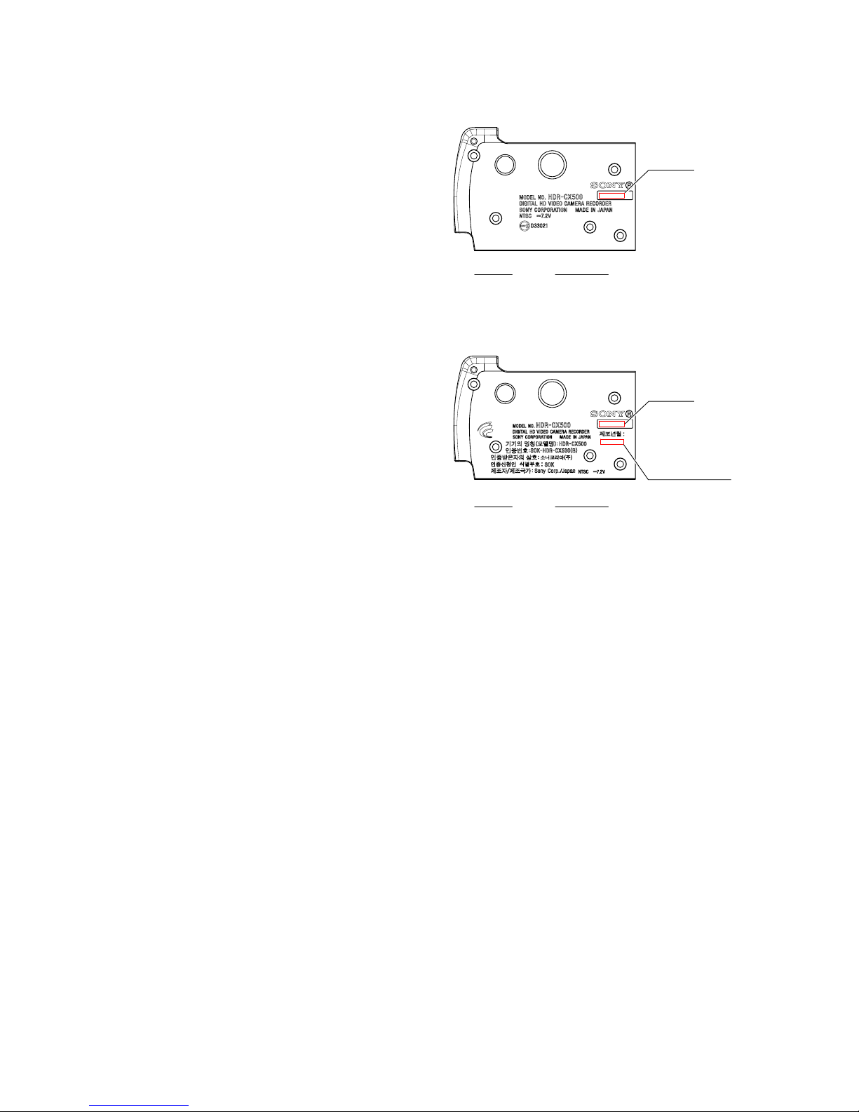
1-7. PRECAUTION ON REPLACING
THE CABINET (BOTTOM) ASSY
(HDR-CX500)
The model display adopts the laser printing method.Therefore, the
cabinet (bottom) assy for replacement differs depending on the
destination.
As similar displays are provided, choose the suitable one for order.
Note 1: After replacing the cabinet (bottom) assy, the serial
number for it will be changed to the one exclusive for
service use. Inform a customer of the serial number
change and change the serial number in the repair data.
Note 2: When replacing the cabinet (bottom) assy for Korea,
affix the “Manufacturing date” label on the specified
location as shown in the figure.
The date label and inset (how to affix) are supplied
together with the cabinet (bottom) assy.
(JAPANESE)
1-7.
キャビネット(底)組立交換時の注意
(HDR-CX500)
機種の表示部はレーザー印字方式を採用しております。
この為,交換用のキャビネット(底)組立は仕向けにより異
なります。類似の表示もありますので,該当するものを選
んで注文して下さい。
注意1: キャビネット(底)組立交換後はシリアルナンバー
がサービス専用のシリアルナンバーに変更されま
す。お客様への案内と修理データのシリアルナン
バー変更を行ってください。
注意2: Korean仕向けキャビネット(底)組立を交換した際
は,「製造時期」を表すラベルを図の指定位置に
貼り付けてください。
なお,キャビネット(底)組立には時期表示ラベ
ル,投げ込み(ラベル貼り方)がセットで供給され
ます。
Part No.
A-1738-996-A
Description
CABINET (BOTTOM (CX500-E23))
Serial No.
Serial No.
* Manufacturing date
Part No.
A-1738-995-A
Description
CABINET (BOTTOM (CX500-KR2))
* Affix the label
HDR-CX500 (E Model)
HDR-CX500 (Korea Model)

1-16
HDR-CX500/CX500E/CX500V/CX500VE/CX505VE/
CX520/CX520E/CX520V/CX520VE_L2
(ENGLISH)
1-8. PRECAUTION ON REPLACING
THE CABINET (BOTTOM) ASSY
(HDR-CX500E)
The model display adopts the laser printing method.Therefore, the
cabinet (bottom) assy for replacement differs depending on the
destination.
As similar displays are provided, choose the suitable one for order.
Note 1: After replacing the cabinet (bottom) assy, the serial
number for it will be changed to the one exclusive for
service use.
Inform a customer of the serial number change and
change the serial number in the repair data.
(JAPANESE)
1-8.
キャビネット(底)組立交換時の注意
(HDR-CX500E)
機種の表示部はレーザー印字方式を採用しております。
この為,交換用のキャビネット(底)組立は仕向けにより異
なります。類似の表示もありますので,該当するものを選
んで注文して下さい。
注意1: キャビネット(底)組立交換後はシリアルナンバー
がサービス専用のシリアルナンバーに変更されま
す。お客様への案内と修理データのシリアルナン
バー変更を行ってください。
Part No.
A-1738-997-A
Description
CABINET (BOTTOM (CX500-CEL))
Serial No.
Serial No.
Part No.
A-1738-998-A
Description
CABINET (BOTTOM (CX500-E34))
HDR-CX500E (North European Model)
HDR-CX500E (E, Hong Kong, Tourist Models)
Serial No.
Part No.
A-1739-016-A
Description
CABINET (BOTTOM (CX500-CN2))
HDR-CX500E (Chinese Model)
1-17
HDR-CX500/CX500E/CX500V/CX500VE/CX505VE/
CX520/CX520E/CX520V/CX520VE_L2
(ENGLISH)
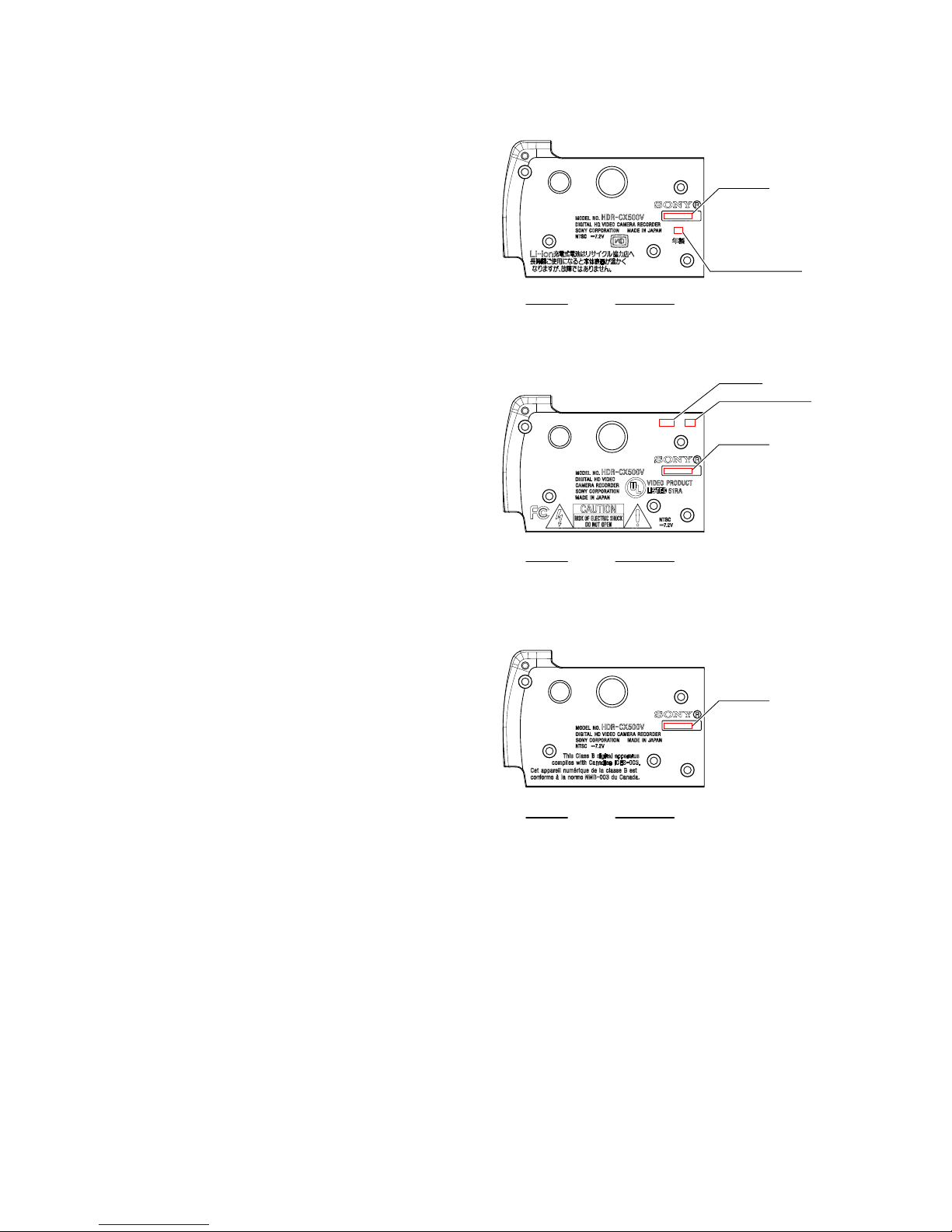
1-9. PRECAUTION ON REPLACING
THE CABINET (BOTTOM) ASSY
(HDR-CX500V)
The model display adopts the laser printing method.Therefore, the
cabinet (bottom) assy for replacement differs depending on the
destination.
As similar displays are provided, choose the suitable one for order.
Note 1: After replacing the cabinet (bottom) assy, the serial
number for it will be changed to the one exclusive for
service use.
Inform a customer of the serial number change and
change the serial number in the repair data.
Note 2: When replacing the cabinet (bottom) assy for US, affix
the “Manufacturing date” label and the “Factory” label
on the specified location as shown in the figure.
The date label and inset (how to affix) are supplied
together with the cabinet (bottom) assy.
Note 3: When replacing the cabinet (bottom) assy for Japanese,
affix the “Manufacturing date” label on the specified
location as shown in the figure.
The date label and inset (how to affix) are supplied
together with the cabinet (bottom) assy.
(JAPANESE)
1-9.
キャビネット(底)組立交換時の注意
(HDR-CX500V)
機種の表示部はレーザー印字方式を採用しております。
この為,交換用のキャビネット(底)組立は仕向けにより異
なります。類似の表示もありますので,該当するものを選
んで注文して下さい。
注意1: キャビネット(底)組立交換後はシリアルナンバー
がサービス専用のシリアルナンバーに変更されま
す。 お客様への案内と修理データのシリアルナン
バー変更を行ってください。
注意2: US仕向けキャビネット(底)組立を交換した際は
「製造時期」を表すラベルと,「製造所」を表す
ラベルを図の指定位置に貼り付けてください。
なお,キャビネット(底)組立には時期表示ラベ
ル,投げ込み(ラベル貼り方)がセットで供給され
ます。
注意3: Japanese仕向けキャビネット(底)組立を交換した
際は,「製造時期」を表すラベルを図の指定位置
に貼り付けてください。
なお,キャビネット(底)組立には時期表示ラベ
ル,投げ込み(ラベル貼り方)がセットで供給され
ます。
* Manufacturing date
* Affix the label
* Manufacturing date
* Factory
* Affix the label
Part No.
A-1738-990-A
Description
CABINET (BOTTOM (CX500-J1))
Serial No.
Serial No.
Part No.
A-1738-992-A
Description
CABINET (BOTTOM (CX500-U2))
HDR-CX500V (Japanese Model)
HDR-CX500V (US Model)
Serial No.
Part No.
A-1738-993-A
Description
CABINET (BOTTOM (CX500-CA2))
HDR-CX500V (Canadian Model)
1-18
HDR-CX500/CX500E/CX500V/CX500VE/CX505VE/
CX520/CX520E/CX520V/CX520VE_L2
(ENGLISH)
1-10.PRECAUTION ON REPLACING
THE CABINET (BOTTOM) ASSY
(HDR-CX500VE)
The model display adopts the laser printing method.Therefore, the
cabinet (bottom) assy for replacement differs depending on the
destination.
As similar displays are provided, choose the suitable one for order.
Note 1: After replacing the cabinet (bottom) assy, the serial
number for it will be changed to the one exclusive for
service use.
Inform a customer of the serial number change and
change the serial number in the repair data.
(JAPANESE)
1-10.
キャビネット(底)組立交換時の注意
(HDR-CX500VE)
機種の表示部はレーザー印字方式を採用しております。
この為,交換用のキャビネット(底)組立は仕向けにより異
なります。類似の表示もありますので,該当するものを選
んで注文して下さい。
注意1: キャビネット(底)組立交換後はシリアルナンバー
がサービス専用のシリアルナンバーに変更されま
す。お客様への案内と修理データのシリアルナン
バー変更を行ってください。
Part No.
A-1738-994-A
Description
CABINET (BOTTOM (CX500-AU2))
Serial No.
HDR-CX500VE (Australian Model)

1-19
HDR-CX500/CX500E/CX500V/CX500VE/CX505VE/
CX520/CX520E/CX520V/CX520VE_L2
(ENGLISH)
1-11.PRECAUTION ON REPLACING
THE CABINET (BOTTOM) ASSY
(HDR-CX505VE)
The model display adopts the laser printing method.Therefore, the
cabinet (bottom) assy for replacement differs depending on the
destination.
As similar displays are provided, choose the suitable one for order.
Note 1: After replacing the cabinet (bottom) assy, the serial
number for it will be changed to the one exclusive for
service use.
Inform a customer of the serial number change and
change the serial number in the repair data.
(JAPANESE)
1-11.
キャビネット(底)組立交換時の注意
(HDR-CX505VE)
機種の表示部はレーザー印字方式を採用しております。
この為,交換用のキャビネット(底)組立は仕向けにより異
なります。類似の表示もありますので,該当するものを選
んで注文して下さい。
注意1: キャビネット(底)組立交換後はシリアルナンバー
がサービス専用のシリアルナンバーに変更されま
す。お客様への案内と修理データのシリアルナン
バー変更を行ってください。
Part No.
A-1739-027-A
Description
CABINET (BOTTOM (CX505-CEN))
Serial No.
HDR-CX505VE (AEP, UK Models)

1-20
HDR-CX500/CX500E/CX500V/CX500VE/CX505VE/
CX520/CX520E/CX520V/CX520VE_L2
(ENGLISH)
1-12. PRECAUTION ON REPLACING
THE CABINET (BOTTOM) ASSY
(HDR-CX520)
The model display adopts the laser printing method.Therefore, the
cabinet (bottom) assy for replacement differs depending on the
destination.
As similar displays are provided, choose the suitable one for order.
Note 1: After replacing the cabinet (bottom) assy, the serial
number for it will be changed to the one exclusive for
service use. Inform a customer of the serial number
change and change the serial number in the repair data.
(JAPANESE)
1-12.
キャビネット(底)組立交換時の注意
(HDR-CX520)
機種の表示部はレーザー印字方式を採用しております。
この為,交換用のキャビネット(底)組立は仕向けにより異
なります。類似の表示もありますので,該当するものを選
んで注文して下さい。
注意1: キャビネット(底)組立交換後はシリアルナンバー
がサービス専用のシリアルナンバーに変更されま
す。お客様への案内と修理データのシリアルナン
バー変更を行ってください。
Part No.
A-1739-023-A
Description
CABINET (BOTTOM (CX520-E23))
Serial No.
HDR-CX520 (E Model)
1-21
HDR-CX500/CX500E/CX500V/CX500VE/CX505VE/
CX520/CX520E/CX520V/CX520VE_L2
(ENGLISH)
1-13. PRECAUTION ON REPLACING
THE CABINET (BOTTOM) ASSY
(HDR-CX520E)
The model display adopts the laser printing method.Therefore, the
cabinet (bottom) assy for replacement differs depending on the
destination.
As similar displays are provided, choose the suitable one for order.
Note 1: After replacing the cabinet (bottom) assy, the serial
number for it will be changed to the one exclusive for
service use.
Inform a customer of the serial number change and
change the serial number in the repair data.
(JAPANESE)
1-13.
キャビネット(底)組立交換時の注意
(HDR-CX520E)
機種の表示部はレーザー印字方式を採用しております。
この為,交換用のキャビネット(底)組立は仕向けにより異
なります。類似の表示もありますので,該当するものを選
んで注文して下さい。
注意1: キャビネット(底)組立交換後はシリアルナンバー
がサービス専用のシリアルナンバーに変更されま
す。 お客様への案内と修理データのシリアルナン
バー変更を行ってください。
Part No.
A-1739-024-A
Description
CABINET (BOTTOM (CX520-CEL))
Serial No.
Serial No.
Part No.
A-1739-025-A
Description
CABINET (BOTTOM (CX520-E34))
HDR-CX520E (North European Model)
HDR-CX520E (E, Tourist Models)
Serial No.
Part No.
A-1739-026-A
Description
CABINET (BOTTOM (CX520-CN2))
HDR-CX520E (Chinese Model)
1-22
HDR-CX500/CX500E/CX500V/CX500VE/CX505VE/
CX520/CX520E/CX520V/CX520VE_L2
Part No.
A-1739-017-A
Description
CABINET (BOTTOM (CX520-J1))
Serial No.
Serial No.
Part No.
A-1739-019-A
Description
CABINET (BOTTOM (CX520-U2))
HDR-CX520V (Japanese Model)
HDR-CX520V (US Model)
Serial No.
Part No.
A-1739-020-A
Description
CABINET (BOTTOM (CX520-CA2))
HDR-CX520V (Canadian Model)
* Manufacturing date
* Affix the label
* Manufacturing date
* Factory
* Affix the label
(ENGLISH)
1-14. PRECAUTION ON REPLACING
THE CABINET (BOTTOM) ASSY
(HDR-CX520V)
The model display adopts the laser printing method.Therefore, the
cabinet (bottom) assy for replacement differs depending on the
destination.
As similar displays are provided, choose the suitable one for order.
Note 1: After replacing the cabinet (bottom) assy, the serial
number for it will be changed to the one exclusive for
service use.
Inform a customer of the serial number change and
change the serial number in the repair data.
Note 2: When replacing the cabinet (bottom) assy for US, affix
the “Manufacturing date” label and the “Factory” label
on the specified location as shown in the figure.
The date label and inset (how to affix) are supplied
together with the cabinet (bottom) assy.
Note 3: When replacing the cabinet (bottom) assy for Japanese,
affix the “Manufacturing date” label on the specified
location as shown in the figure.
The date label and inset (how to affix) are supplied
together with the cabinet (bottom) assy.
(JAPANESE)
1-14.
キャビネット(底)組立交換時の注意
(HDR-CX520V)
機種の表示部はレーザー印字方式を採用しております。
この為,交換用のキャビネット(底)組立は仕向けにより異
なります。類似の表示もありますので,該当するものを選
んで注文して下さい。
注意1: キャビネット(底)組立交換後はシリアルナンバー
がサービス専用のシリアルナンバーに変更されま
す。 お客様への案内と修理データのシリアルナン
バー変更を行ってください。
注意2: US仕向けキャビネット(底)組立を交換した際は
「製造時期」を表すラベルと,「製造所」を表す
ラベルを図の指定位置に貼り付けてください。
なお,キャビネット(底)組立には時期表示ラベ
ル,投げ込み(ラベル貼り方)がセットで供給され
ます。
注意3: Japanese仕向けキャビネット(底)組立を交換した
際は,「製造時期」を表すラベルを図の指定位置
に貼り付けてください。
なお,キャビネット(底)組立には時期表示ラベ
ル,投げ込み(ラベル貼り方)がセットで供給され
ます。
1-23E
HDR-CX500/CX500E/CX500V/CX500VE/CX505VE/
CX520/CX520E/CX520V/CX520VE_L2
Part No.
A-1739-022-A
Description
CABINET (BOTTOM (CX520-AU2))
Serial No.
Serial No.
Part No.
A-1739-021-A
Description
CABINET (BOTTOM (CX520-CEN))
HDR-CX520VE (Australian Model)
HDR-CX520VE (AEP, UK Models)
(ENGLISH)
1-15. PRECAUTION ON REPLACING
THE CABINET (BOTTOM) ASSY
(HDR-CX520VE)
The model display adopts the laser printing method.Therefore, the
cabinet (bottom) assy for replacement differs depending on the
destination.
As similar displays are provided, choose the suitable one for order.
Note 1: After replacing the cabinet (bottom) assy, the serial
number for it will be changed to the one exclusive for
service use.
Inform a customer of the serial number change and
change the serial number in the repair data.
(JAPANESE)
1-15.
キャビネット(底)組立交換時の注意
(HDR-CX520VE)
機種の表示部はレーザー印字方式を採用しております。
この為,交換用のキャビネット(底)組立は仕向けにより異
なります。類似の表示もありますので,該当するものを選
んで注文して下さい。
注意1: キャビネット(底)組立交換後はシリアルナンバー
がサービス専用のシリアルナンバーに変更されま
す。 お客様への案内と修理データのシリアルナン
バー変更を行ってください。
 Loading...