

Page 1
DCR-TRV890E/TRV900/TRV900E
RMT-811/812
US Model
SERVICE MANUAL
Canadian Model
DCR-TRV900
AEP Model
UK Model
DCR-TRV890E/TRV900E
E Model
Hong Kong Model
Tourist Model
DCR-TRV900/TRV900E
C MECHANISM
Difference table
Model
Color System
Remote Commander
Line recording
The POWER switch
position during playback
Base Band Input
DCR-TRV890E
Ver 1.0 1998.08
DCR-TRV900
PAL
RMT-812
—
PLAYER
—
NTSC
RMT-811
Photo: DCR-TRV900E
RMT-811
DCR-TRV900E
PAL
VTR
SPECIFICATIONS
Australian Model
Chinese Model
DCR-TRV900E
For MECHANISM ADJUSTMENTS, refer to the
“DV MECHANICAL ADJUSTMENT MANUAL
C MECHANISM ” (9-974-050-11)
MICROFILM
— Continued on next page —
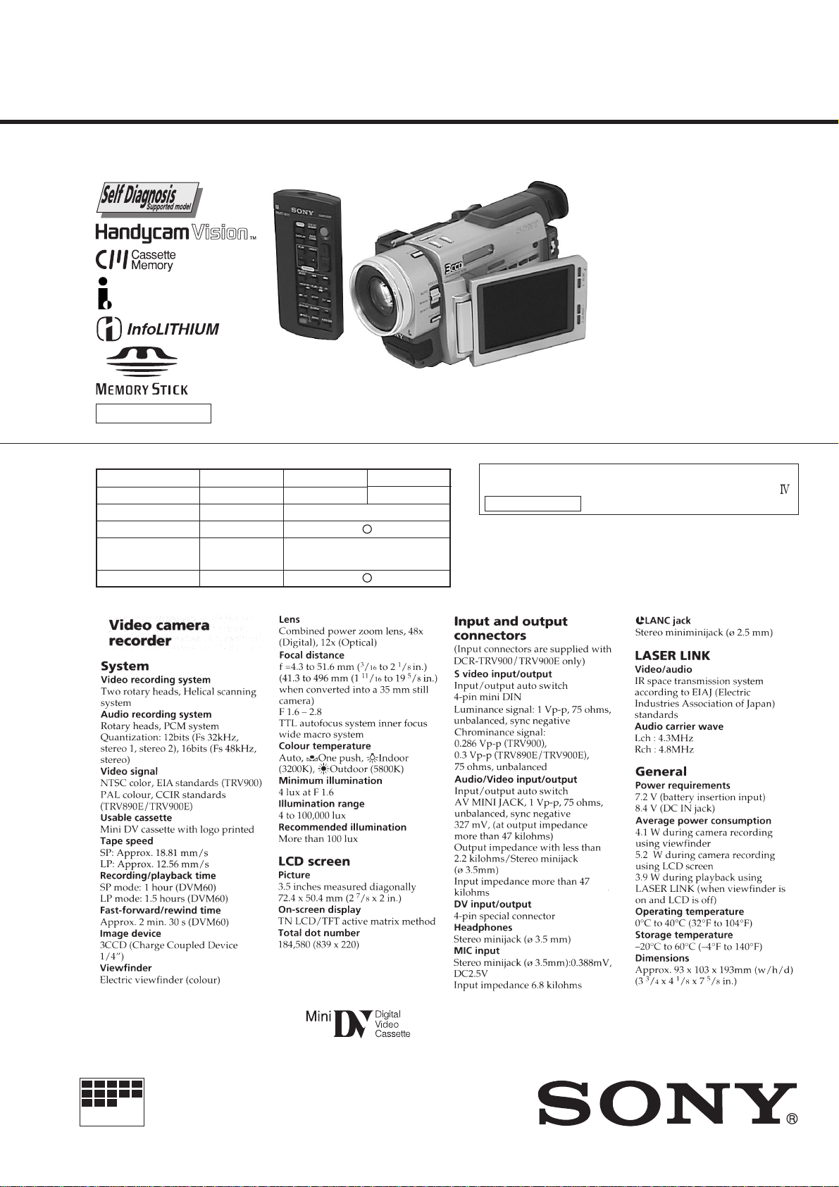
DIGITAL VIDEO CAMERA RECORDER
Page 2
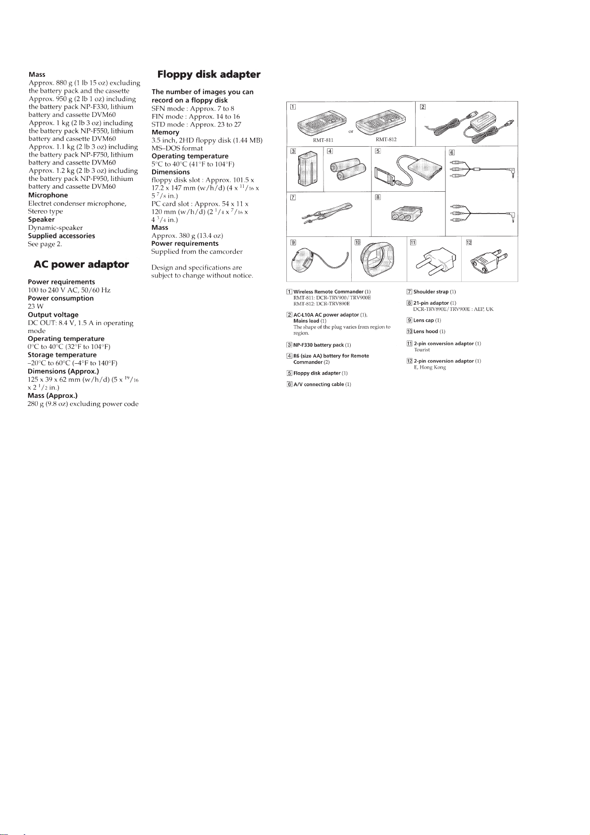
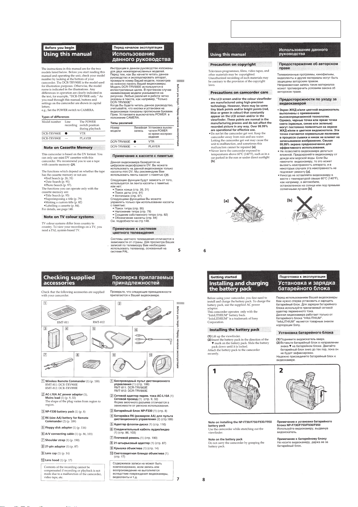
• SUPPLIED ACCESSORIES
Check that the following accessories are supplied with your
camcorder.
SAFETY-RELATED COMPONENT WARNING!!
COMPONENTS IDENTIFIED BY MARK ! OR DOTTED LINE WITH
MARK ! ON THE SCHEMATIC DIAGRAMS AND IN THE PARTS
LIST ARE CRITICAL TO SAFE OPERATION. REPLACE THESE
COMPONENTS WITH SONY PARTS WHOSE PART NUMBERS
APPEAR AS SHOWN IN THIS MANUAL OR IN SUPPLEMENTS
PUBLISHED BY SONY.
SAFETY CHECK-OUT
After correcting the original service problem, perform the following
safety checks before releasing the set to the customer.
1. Check the area of your repair for unsoldered or poorly-soldered
connections. Check the entire board surface for solder splashes
and bridges.
2. Check the interboard wiring to ensure that no wires are
"pinched" or contact high-wattage resistors.
3. Look for unauthorized replacement parts, particularly
transistors, that were installed during a previous repair . Point
them out to the customer and recommend their replacement.
ATTENTION AU COMPOSANT A YANT RAPPORT
À LA SÉCURITÉ!
LES COMPOSANTS IDENTIFÉS PAR UNE MARQUE ! SUR LES
DIAGRAMMES SCHÉMATIQUES ET LA LISTE DES PIÈCES SONT
CRITIQUES POUR LA SÉCURITÉ DE FONCTIONNEMENT. NE
REMPLACER CES COMPOSANTS QUE PAR DES PIÈSES SONY
DONT LES NUMÉROS SONT DONNÉS DANS CE MANUEL OU
DANS LES SUPPÉMENTS PUBLIÉS P AR SONY.
4. Look for parts which, through functioning, show obvious signs
of deterioration. Point them out to the customer and
recommend their replacement.
5. Check the B+ voltage to see it is at the values specified.
6. Flexible Circuit Board Repairing
• Keep the temperature of the soldering iron around 270˚C
during repairing.
• Do not touch the soldering iron on the same conductor of the
circuit board (within 3 times).
• Be careful not to apply force on the conductor when soldering
or unsoldering.
— 2 —
Page 3

T ABLE OF CONTENTS
SERVICE NOTE
1. Power Supply During Repairs ............................................6
2. How to Take a Cassette Out When the Main Power Cannot
Be Turned On ..................................................................... 6
SELF-DIAGNOSIS FUNCTION
1. Self-Diagnosis Function ..................................................... 7
2. Self-Diagnosis Display....................................................... 7
3. Service Mode Display ........................................................ 7
3-1. Display Method .................................................................. 7
3-2. Switching of Backup No. ................................................... 7
3-3. End of Display.................................................................... 7
4. Self-Diagnosis Code Table ................................................. 8
1. GENERAL
Before you begin
Using this manual ..................................................................1-1
Checking supplied accessories ..............................................1-1
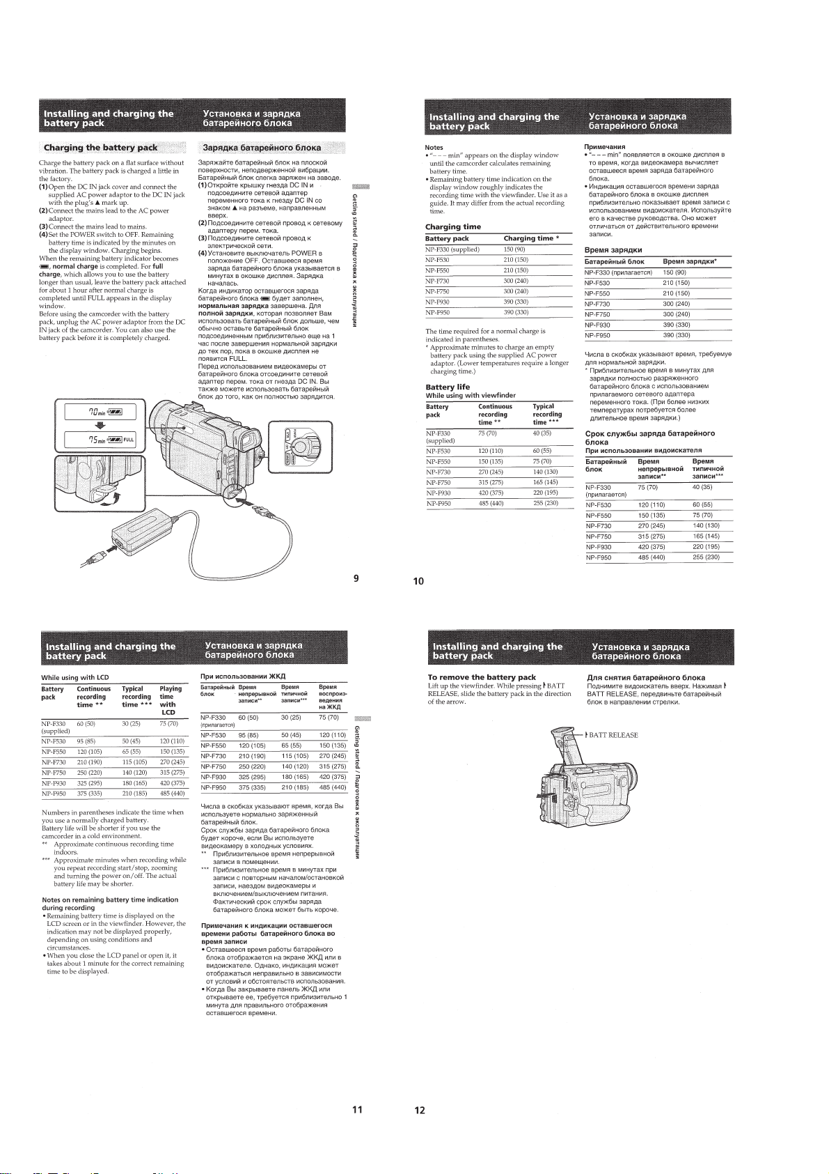
Getting started
Installing and charging the battery pack ................................1-1
Inserting a cassette .................................................................1-3
Basic operations
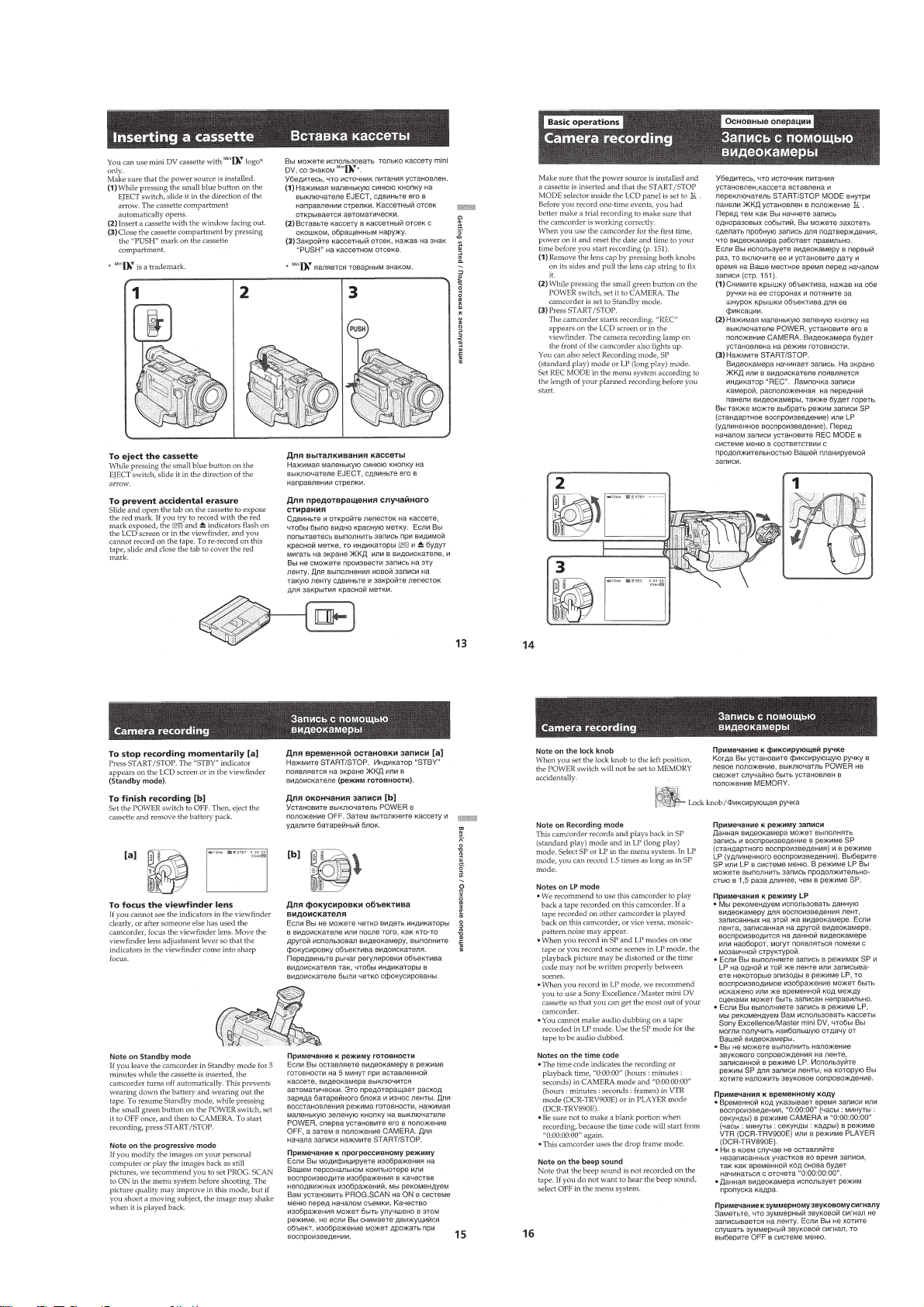
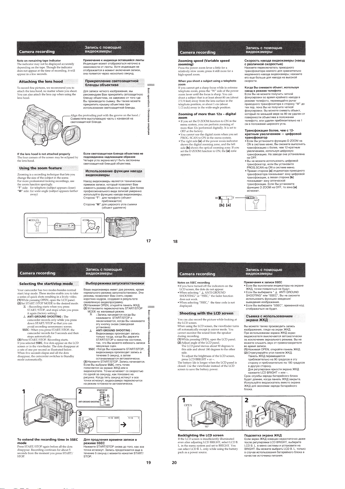
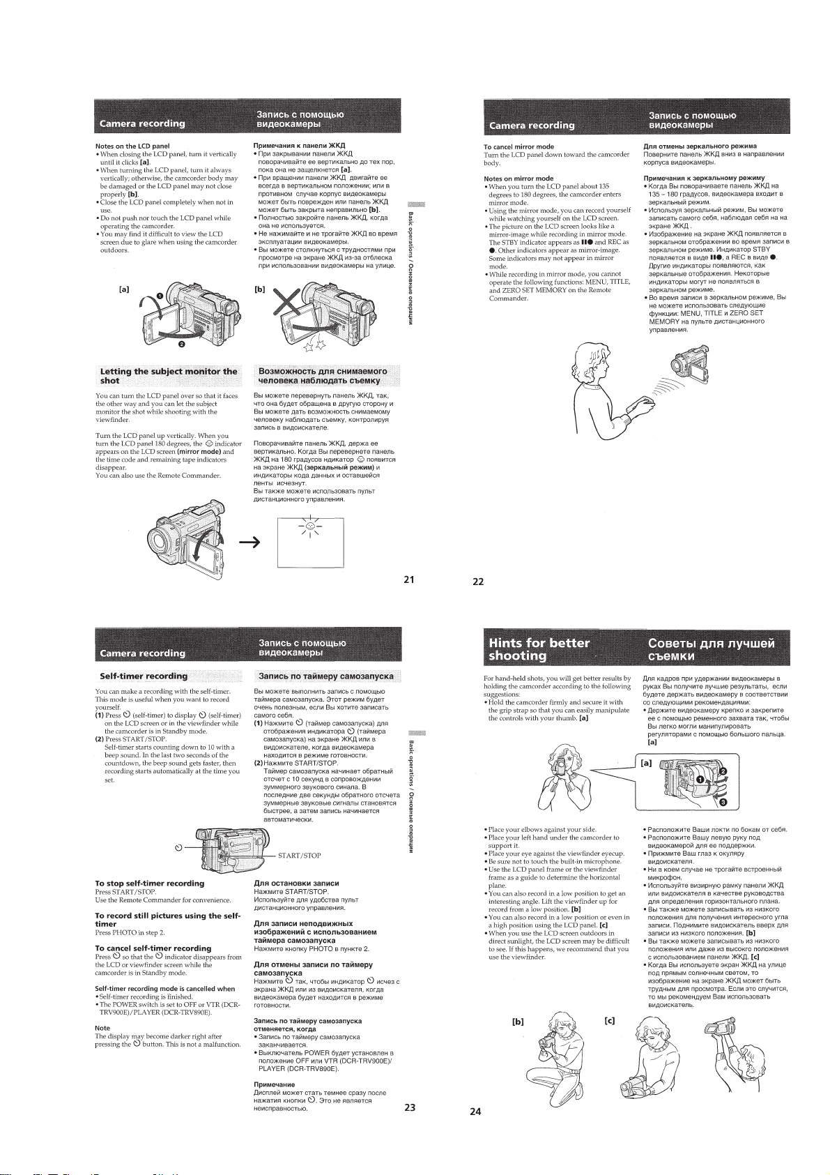
Camera recording...................................................................1-3
Hints for better shooting ........................................................1-5
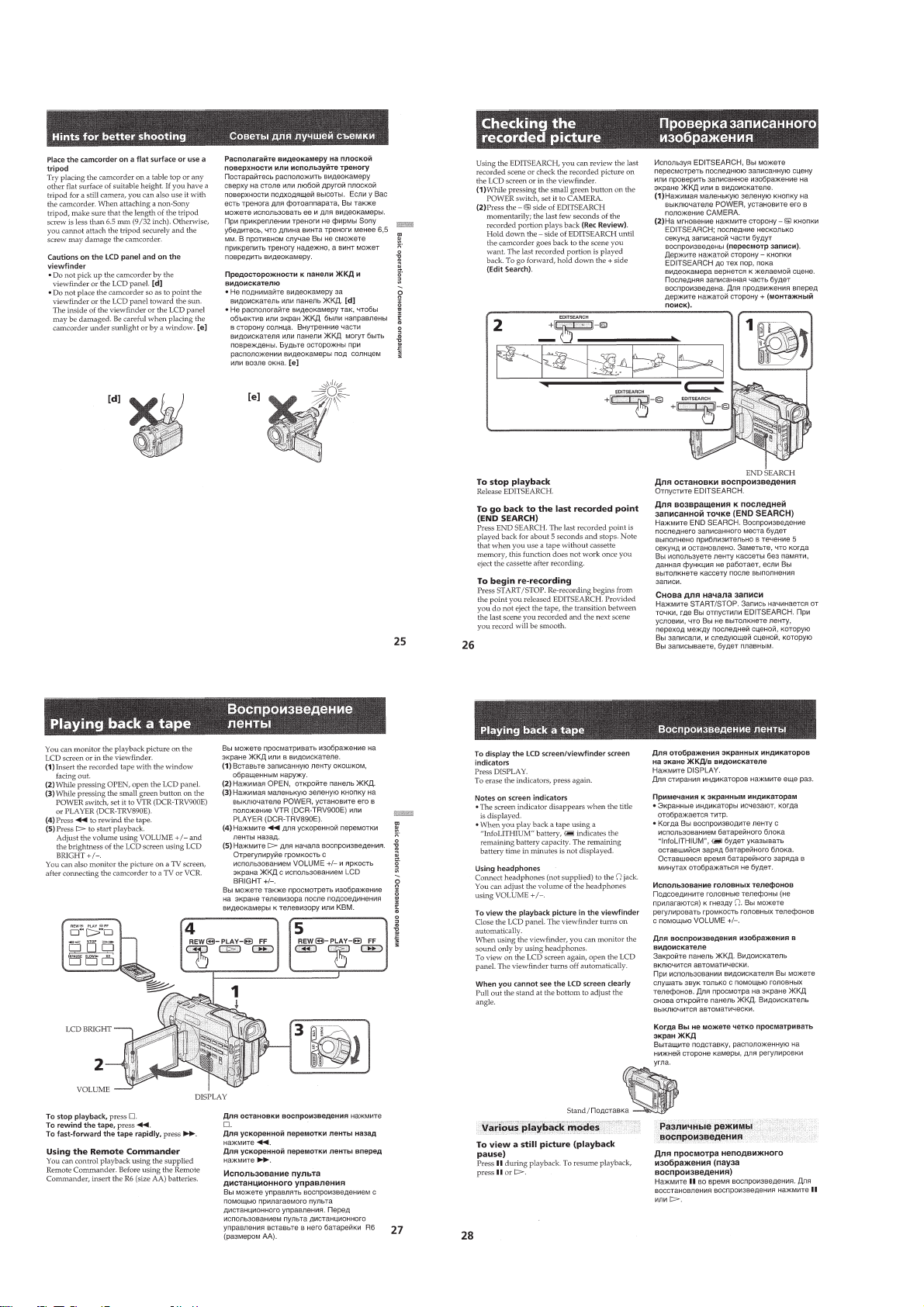
Checking the recorded picture ...............................................1-6
Playing back a tape ................................................................1-6
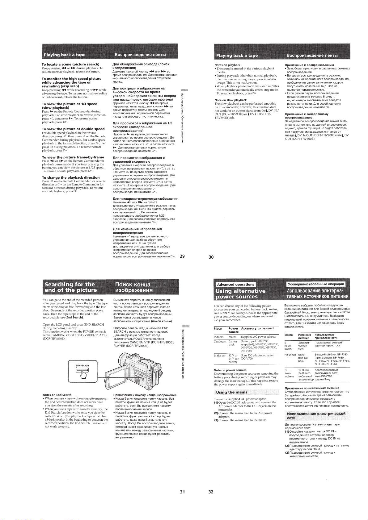
Searching for the end of the picture.......................................1-7
Advanced operations
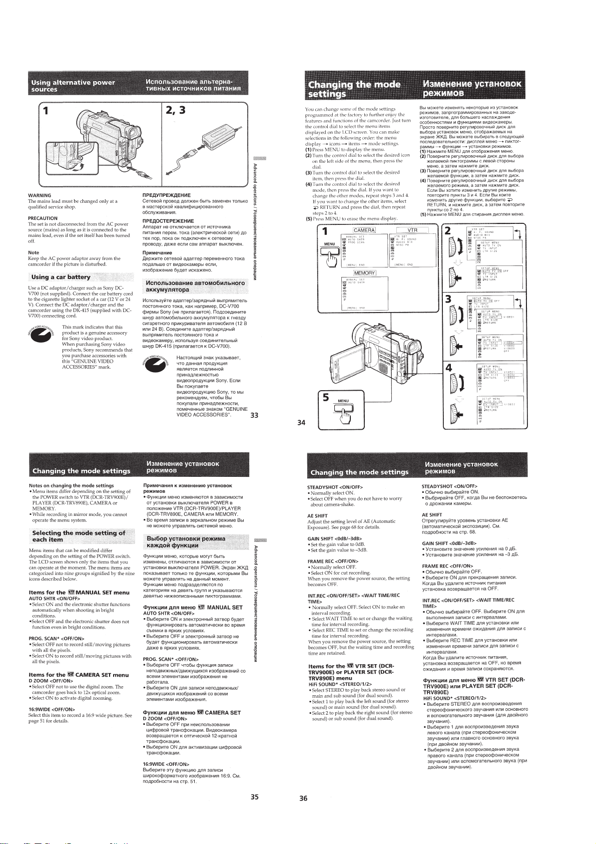
Using alternative power sources ............................................1-7
Changing the mode settings...................................................1-8
Photo recording....................................................................1-10
Shooting with all the pixels - PROG.SCAN........................1-11
Using the FADER function .................................................. 1-11
Shooting with backlighting..................................................1-12
Using the wide mode function .............................................1-12
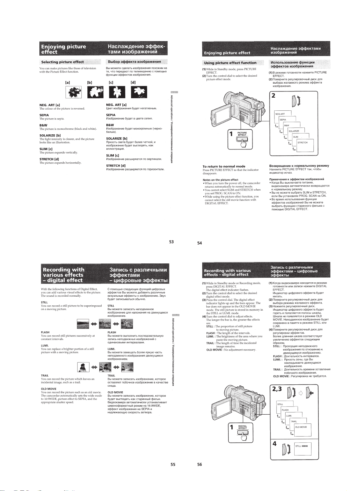
Enjoying picture effect.........................................................1-13
Recording with various effects - digital effect.....................1-13
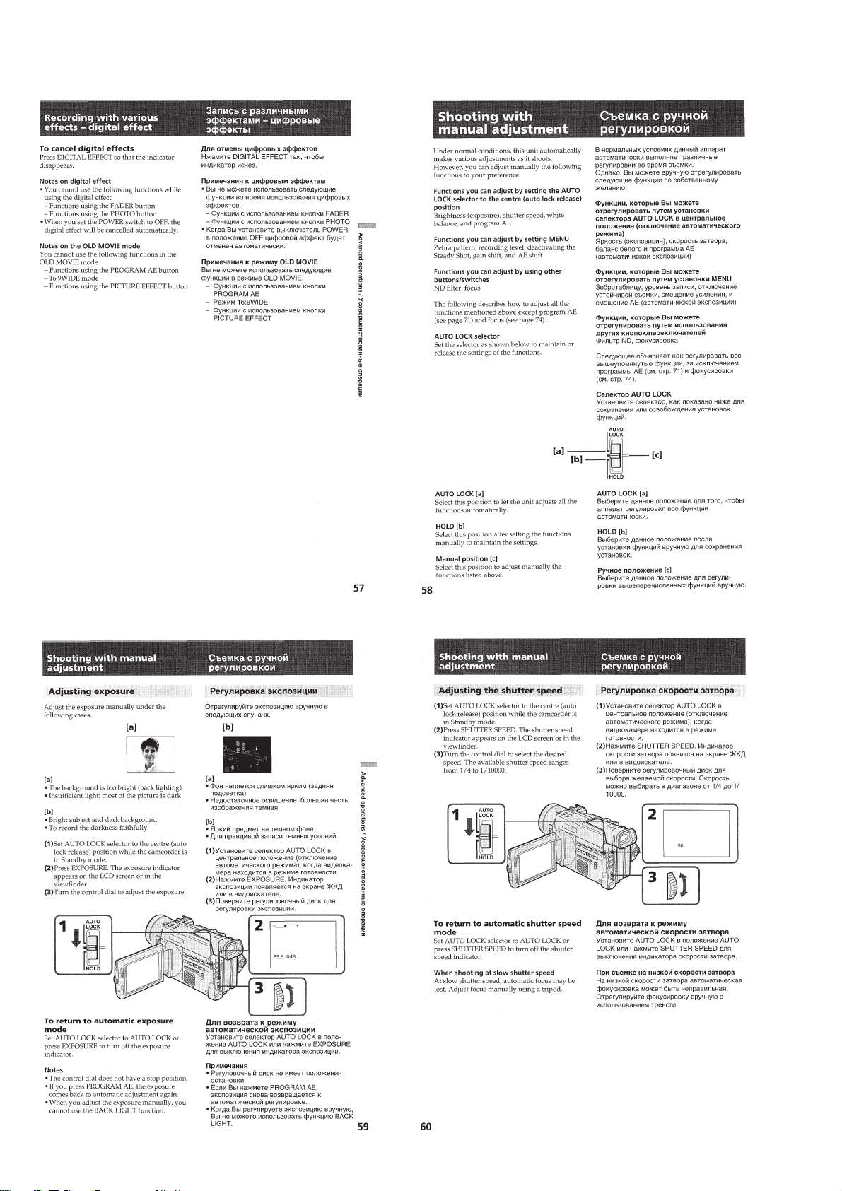
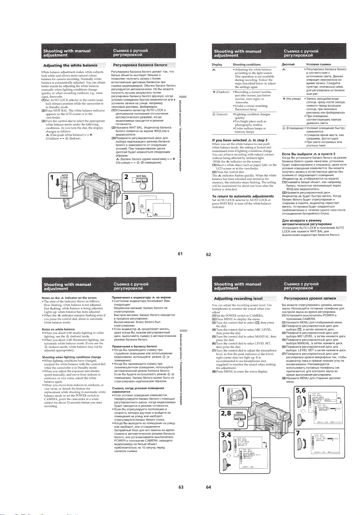
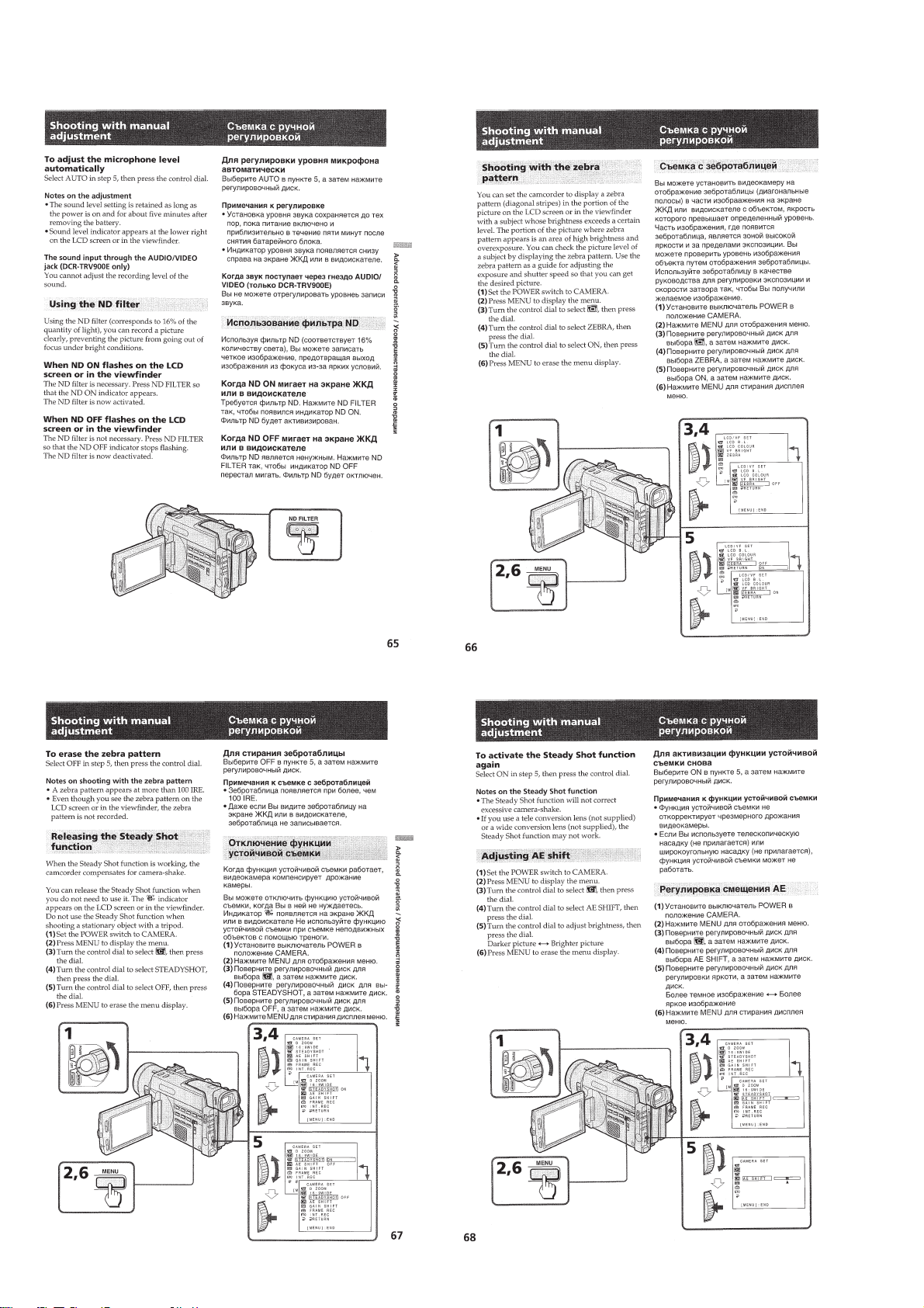
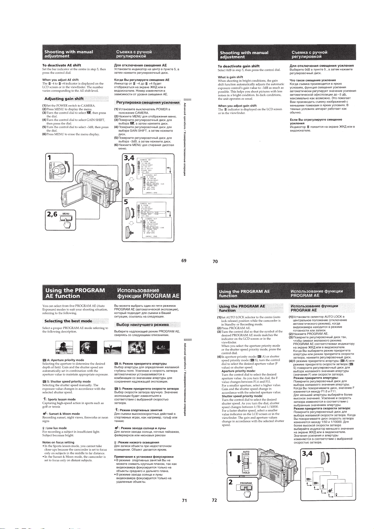
Shooting with manual adjustment ....................................... 1-14
Using the PROGRAM AE function ..................................... 1-17
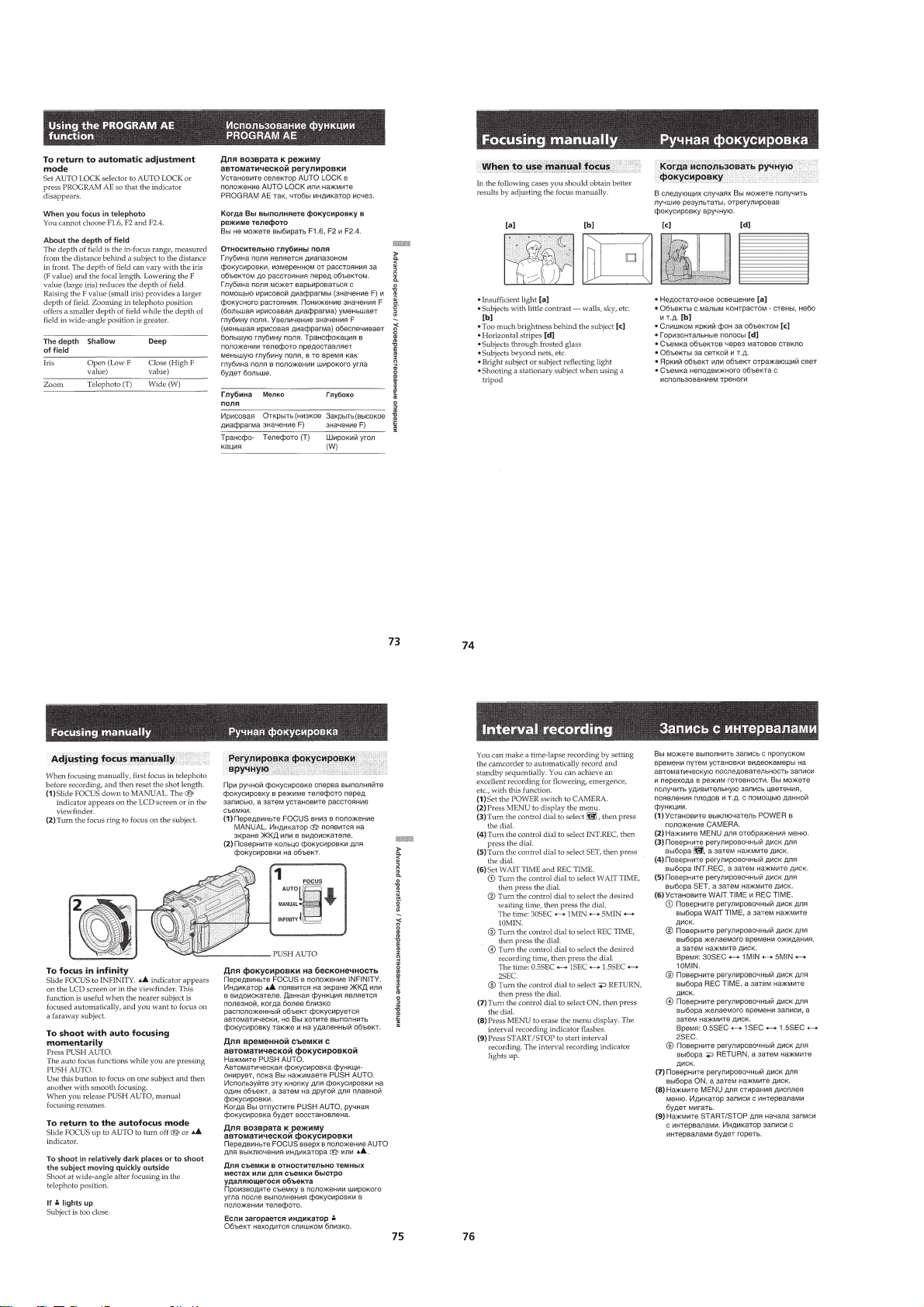
Focusing manually...............................................................1-18
Interval recording.................................................................1-18
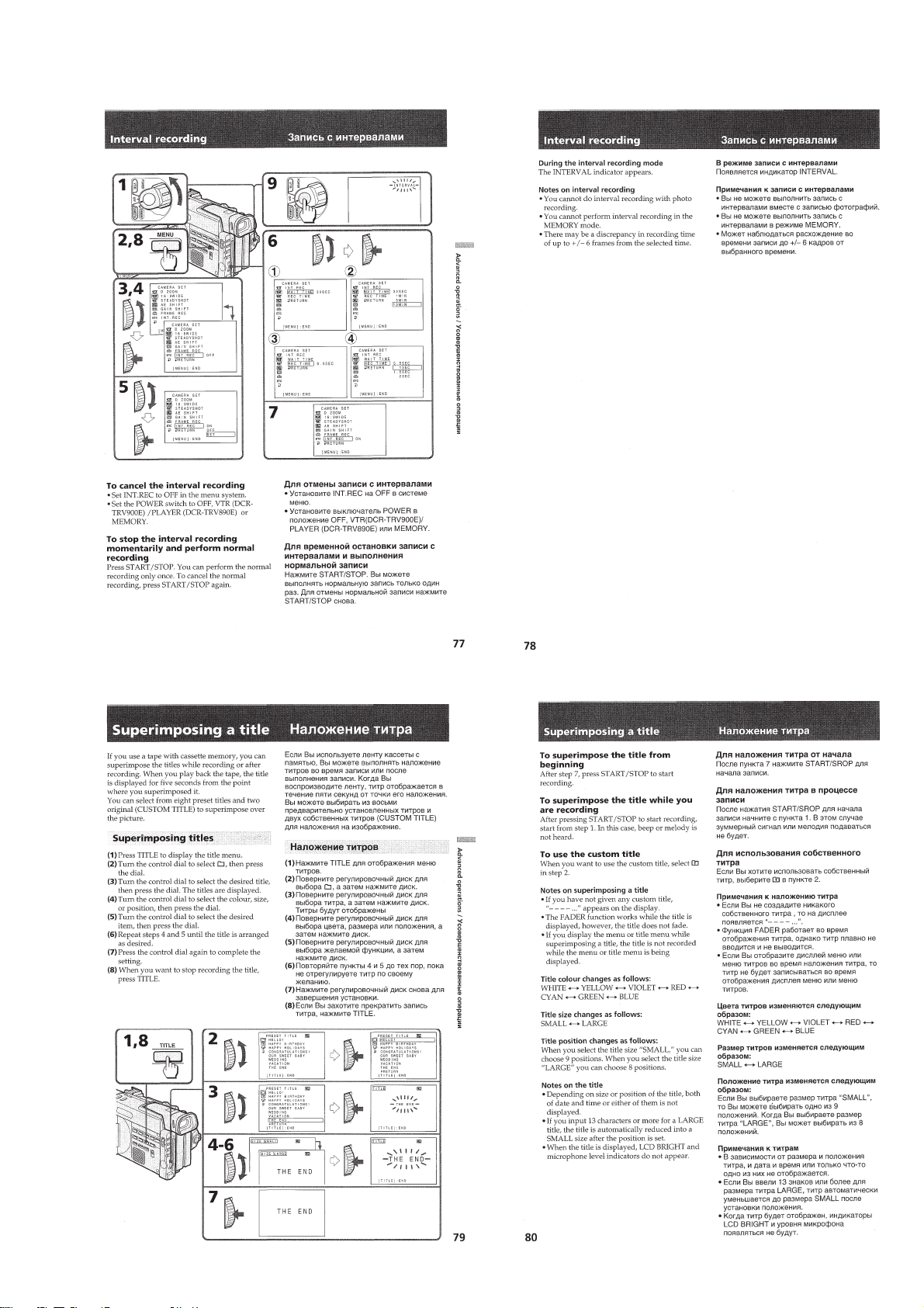
Superimposing a title ...........................................................1-19
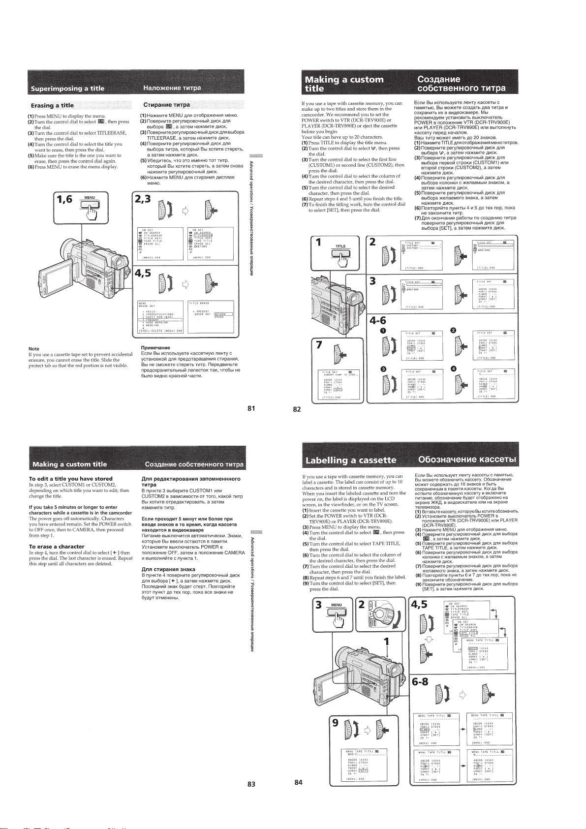
Making a custom title ..........................................................1-20
Labelling a cassette..............................................................1-20
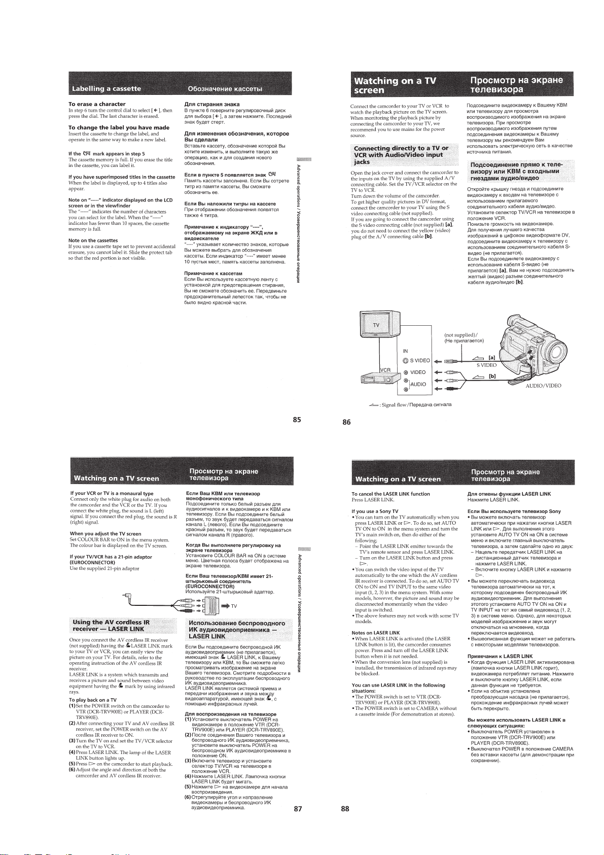
Watching on a TV screen ..................................................... 1-21
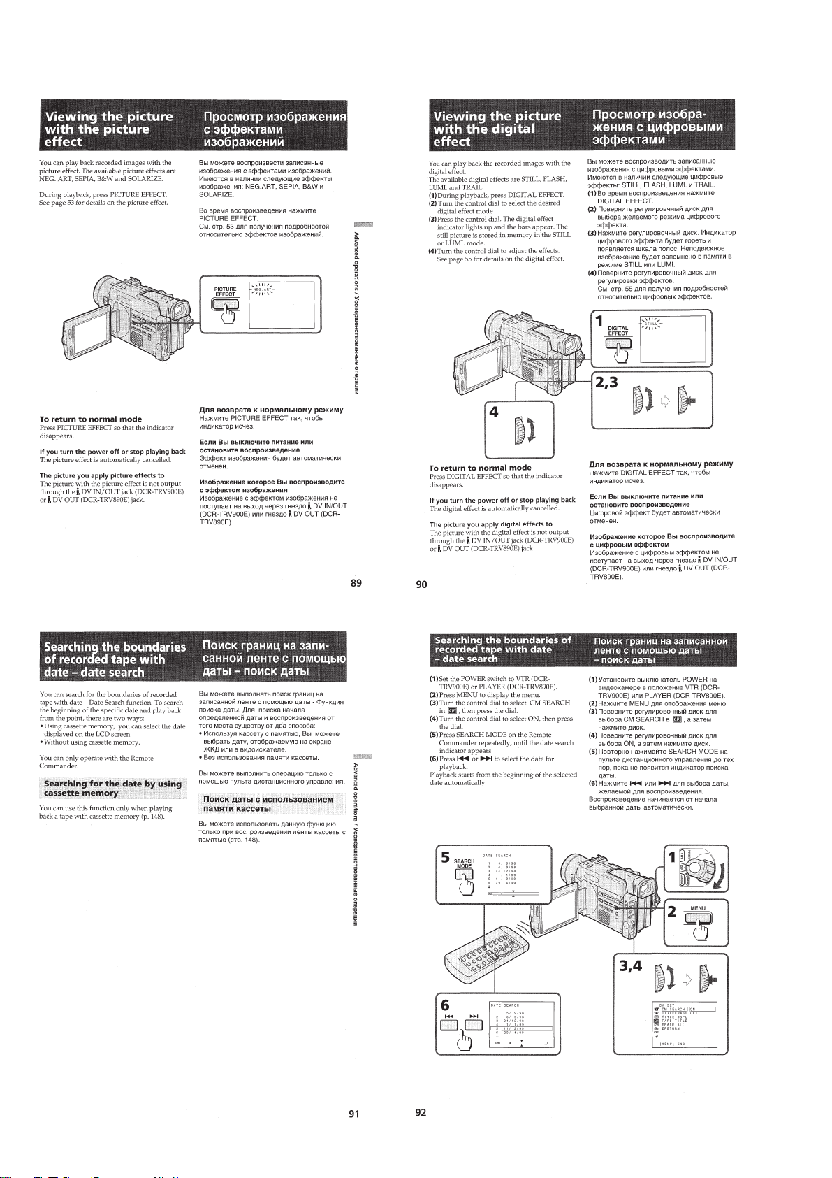
Viewing the picture with the picture effect ..........................1-22
Searching the boundaries of recorded tape with date - date
search ...................................................................................1-22
Searching the boundaries of recorded tape with title - title
search ...................................................................................1-23
Searching for a photo - photo search/photo scan.................1-24
Returning to a preregistered position...................................1-25
Display recording data - data code function ........................1-25
Editing onto another tape.....................................................1-25
Editing partially on a mini DV tape - DV synchro-editing .. 1-26
Recording from a VCR or TV (DCR-TRV900E only) ........ 1-26
Replacing recording on a tape - insert editing
(DCR-TRV900E only) .........................................................1-27
Audio dubbing (DCR-TRV900E only) ................................ 1-27
Memory card slot operations
Using the memory card slot - introduction .......................... 1-28
Recording an image from a mini DV tape as a still image ..1-31
Copying still images from a mini DV tape - photo save ......1-32
Recording still images on PC cards (not supplied) - memory
photo recording ....................................................................1-32
Viewing a still picture - memory photo playback ................ 1-33
Preventing accidental erasure - PROTECT..........................1-34
Deleting images ...................................................................1-35
Copying the image recorded with the memory card slot to
mini DV tapes (DCR-TRV900E only).................................1-35
Playing back images in a continuous loop - SLIDE SHOW ..1-36
Additional information
Usable cassettes and playback modes..................................1-36
Charging the vanadium-lithium battery in the camcorder ...1-37
Resetting the date and time..................................................1-37
Simple setting of clock by time difference .......................... 1-38
Tips for using the battery pack ............................................ 1-38
Maintenance information and precautions...........................1-40
Using your camcorder abroad..............................................1-41
Trouble check ......................................................................1-41
Self-diagnosis function ........................................................1-42
Identifying the parts .............................................................1-43
Warning indicators ...............................................................1-46
2. DISASSEMBLY
2-1. Cabinet (Upper) Assembly, Front Panel Assembly .........2-1
2-2. Battery Panel Assembly...................................................2-2
2-3. Cabinet (R) Assembly, Cabinet (L) Assembly ................2-2
2-4. Mechanism Deck, Lens Assembly, VC-208, VI-151,
SE-75 Boards...................................................................2-3
2-5. JK-163 Board ..................................................................2-3
2-6. CK-80 Board ...................................................................2-4
2-7. LCD Panel Assembly, Hinge Assembly ..........................2-4
2-8. PD-101 Board..................................................................2-5
2-9. BT Terminal Board, DC-IN Connector ...........................2-5
2-10. ED-48, VF-121 Boards ....................................................2-6
2-11. LB-55 Board....................................................................2-6
2-12. MA-333 Board ................................................................ 2-7
2-13. Service Position (Mainly for and voltag e measurement)...2-7
2-14. Circuit Boards Location ..................................................2-8
2-15. Flexible Boards Location ................................................2-9
3. BLOCK DIAGRAMS
3-1. Overall Block Diagram ...................................................3-1
3-2. Power Block Diagram .....................................................3-5
4. PRINTED WIRING BOARDS AND
SCHEMATIC DIAGRAMS
4-1. Frame Schematic Diagram-1...........................................4-1
Frame Schematic Diagram-2...........................................4-5
4-2. Printed Wiring Boards and Schematic Diagrams............4-9
• CD-202 (CCD Imager) Schematic Diagram ...............4-11
• CD-202 (CCD Imager) Printed Wiring Board............4-13
• VC-208 (Sample Hold & AGC, Camera Processor, Base
Band Input, Motor Drive, VAP Driver, Card Control,
PWN Control, Honey, PCMCIA Control)
Printed Wiring Board ....................................4-17
• VC-208 (Sample Hold & AGC)(1/7)
Schematic Diagram ....................................... 4-24
• VC-208 (Camera Processor)(2/7)
Schematic Diagram ....................................... 4-27
• VC-208 (Base Band Input)(3/7)
Schematic Diagram ....................................... 4-32
• VC-208 (Motor Drive)(4/7)
Schematic Diagram ....................................... 4-35
• SE-75 (YAW/Pitch Sensor)
Printed Wiring Board ....................................4-39
• VC-208 (VAP Driver)(5/7)
Schematic Diagram ....................................... 4-40
• VC-208 (Card Control, PWM Control)(6/7)
Schematic Diagram ....................................... 4-43
• VC-208 (Honey, PCMCIA Control)(7/7)
Schematic Diagram ....................................... 4-47
— 3 —
Page 4

• VI-151 (REC/PB AMP)(1/10)
Schematic Diagram ....................................... 4-51
• VI-151 (Timing Generator)(2/10)
Schematic Diagram ....................................... 4-55
• VI-151 (Video Interface)(3/10)
Schematic Diagram ....................................... 4-57
• VI-151 (DCT/IDCT)(4/10)
Schematic Diagram ....................................... 4-62
• VI-151 (IR Transmitter)(5/10)
Schematic Diagram ....................................... 4-65
• VI-151 (Audio Processor)(6/10)
Schematic Diagram ....................................... 4-68
• VI-151 (HI Control)(7/10)
Schematic Diagram ....................................... 4-71
• VI-151 (Mechanism Control)(8/10)
Schematic Diagram ....................................... 4-77
• VI-151 (Drum/Capstan Motor Drive)(9/10)
Schematic Diagram ....................................... 4-79
• VI-151 (DC/DC Converter)(10/10)
Schematic Diagram ....................................... 4-83
• FP-594 (Loading Motor, ST Reel Sensor)
Printed Wiring Board ....................................4-87
• FK-4880 (User Control) Schematic Diagram .............4-88
• VI-151 (REC PB AMP, Timing Generator, Video
Interface, DCT/IDCT, IR Transmitter, Audio Processor,
HI Control, Mechanism Control, Drum/Capstan Motor
Drive, DC/DC Converter)
Printed Wiring Board ....................................4-91
• FP-21 (Focus SW) Flexible Board..............................4-96
• FP-22 (MIC Jack) Flexible Board...............................4-96
• MA-333 (Stereo MIC AMP)
Printed Wiring Board ....................................4-97
• RI-10 (Sircs Receiver)
Printed Wiring Board ....................................4-98
• MA-333 (Stereo MIC AMP)
Schematic Diagram ....................................... 4-99
• RI-10 (Sircs Receiver)
Schematic Diagram ..................................... 4-101
• FP-16 (Panel Switch) Flexible Board ......................4-103
• FP-18 (User Control) Flexible Board .......................4-103
• ED-48 (User Control) Schematic Diagram...............4-103
• CK-80 (User Control) Schematic Diagram ..............4-104
• CK-80 (User Control) Printed Wiring Board............4-107
• ED-48 (User Control) Printed Wiring Board............4-110
• FP-23 (S Video) Flexible Board................................4-111
• JK-163 (Audio/Video IN/OUT)
Printed Wiring Board and
Schematic Diagram ..................................... 4-112
• PD-101 (RGB Driver)(1/2)
Schematic Diagram ..................................... 4-115
• PD-101 (Timing Generator, Back-Light)(2/2)
Schematic Diagram ..................................... 4-119
• PD-101 (RGB Driver, Timing Generator, Back-Light)
Printed Wiring Board ..................................4-121
• FP-19 (User Control) Flexible Board .......................4-121
• VF-121 (Color EVF) Printed Wiring Board .............4-123
• VF-121 (Color EVF) Schematic Diagram ................4-125
• LB-55 (EVF Back-Light)
Printed Wiring Board and
Schematic Diagram ..................................... 4-128
5. ADJUSTMENTS
5-1. Camera Section Adjustment ............................................5-1
1-1. Preparations before Adjustment (Camera Section) .........5-1
1-1-1.List of Service Tools ........................................................ 5-1
1-1-2. Preparations ....................................................................5-2
1-1-3.Precaution ........................................................................5-4
1. Setting the Switch............................................................ 5-4
2. Order of Adjustments ......................................................5-4
3. Subjects ...........................................................................5-4
1-2. Initialization of F, E Page Data........................................5-5
1. Initializing the F, E Page Data .........................................5-5
2. Modification of F, E Page Data .......................................5-5
3. F Page Table ....................................................................5-5
4. E Page Table ....................................................................5-8
1-3. Camera System Adjustments.........................................5-10
1. 27MHz Origin Oscillation Adjustment
(VC-208 board) .............................................................5-10
2. IRIS & ND HALL Auto Adjustment.............................5-10
3. Offset Adjustment..........................................................5-11
4. Flange Back Adjustment ...............................................5-12
4-1. Flange Back Adjustment (1)..........................................5-12
4-2. Flange Back Adjustment (2)..........................................5-12
5. Flange Back Check........................................................ 5-13
6. Picture Frame Setting ....................................................5-13
7. Pre White Balance Data Input ....................................... 5-14
8. Auto White Balance Standard Data Input .....................5-14
9. MAX GAIN Adjustment ...............................................5-15
10. LV Standard Data Input .................................................5-15
11. White Balance ND Filter Compensation Adjustment ...5-16
12. Auto White Balance Adjustment ...................................5-16
13. Color Reproduction Adjustment (ND Filter OFF) ........ 5-17
14. Color Reproduction Adjustment (ND Filter ON)..........5-17
15. White Balance Check ....................................................5-18
16. PSD Sensor Gain Adjustment........................................5-19
16-1. PSD Sensor Gain Adjustment (1)..................................5-19
16-2. PSD Sensor Gain Adjustment (2)..................................5-20
17. Angular Velocity Sensor Sensitivity Adjustment ..........5-21
1-4. Color Electronic Viewfinder System Adjustment ..........5-22
1. VCO Adjustment (VF-121 board).................................5-22
2. Bright Adjustment (VF-121 board) ...............................5-23
3. Contrast Adjustment (VF-121 board)............................5-23
4. Backlight Consumption Current Adjustment
(VF-121 board)..............................................................5-24
5. White Balance Adjustment (VF-121 board)..................5-24
1-5. LCD SYSTEM ADJUSTMENT ...................................5-25
1. VCO Adjustment (PD-101 board).................................5-25
2. D range Adjustment (PD-101 board).............................5-26
3. Bright Adjustment (PD-101 board) ...............................5-26
4. Contrast Adjustment (PD-101 board)............................5-27
5. V-COM Level Adjustment (PD-101 board) ..................5-27
6. V-COM Adjustment (PD-101 board) ............................5-28
7. White Balance Adjustment (PD-101 board)..................5-28
5-2. Mechanism Section Adjustment.................................... 5-29
2-1. How to Enter Record Mode without Cassette ...............5-29
2-2. How to Enter Playback Mode without Cassette ............5-29
2-3. Tape Path Adjustment....................................................5-29
1. Preparations for Adjustment..........................................5-29
2. Procedure after Operations ............................................5-29
5-3. Video Section Adjustments ...........................................5-30
3-1. Preparations before Adjustments...................................5-30
3-1-1.Equipment Required ......................................................5-30
3-1-2.Precautions on Adjusting...............................................5-31
3-1-3.Adjusting Connectors ....................................................5-32
3-1-4.Connecting the Equipment ............................................5-32
3-1-5.Checking the Input Signals............................................5-32
3-1-6.Alignment Tapes............................................................5-33
3-1-7.Input/Output Level and Impedance ...............................5-33
3-2. Initialization of B, C, D Page Data................................5-34
1. Initializing the C Page Data...........................................5-34
2. Modification of C Page Data.........................................5-34
3. C Page Table .................................................................. 5-34
4. Initializing the D Page Data ..........................................5-36
5. Modification of D Page Data.........................................5-36
— 4 —
Page 5

6. D Page Table..................................................................5-36
7. Initializing the B Page Data...........................................5-38
8. Modification of B Page Data.........................................5-38
9. B Page Table .................................................................. 5-38
3-3. System Control System Adjustment..............................5-41
1. Battery End Adjustment (VI-151 Board) ......................5-41
3-4. Servo and RF System Adjustments ............................... 5-42
1. Cap FG Duty Adjustment (VI-151 Board)....................5-42
2. T Reel FG Duty Adjustment (VI-151 Board)................5-42
3. PLL f0 & LPF f0 Adjustment (VI-151 Board)...............5-42
4. Switching Position Adjustment (VI-151 Board) ........... 5-43
5. AGC Center Level Adjustment (VI-151 Board)............ 5-43
6. APC & AEQ Adjustment (VI-151 Board).....................5-44
7. PLL f0 & LPF f0 Final Adjustment (VI-151 Board)......5-44
3-5. Video System Adjustments............................................5-45
3-5-1.Base Band Block Adjustments ......................................5-45
1. Chroma BPF f0 Adjustment (VI-151 Board).................5-45
2. S Video Out Y Level Adjustment (VI-151 Board) ........5-45
3. S Video Out Chroma Level Adjustment
(VI-151 Board) ..............................................................5-46
4. AV Out Y, Chroma Le vel Adjustment (VI-151 Board) ....5-46
5. PLL Adjustment (VC-208 Board) .................................5-47
3-5-2.BIST Check ...................................................................5-48
1. Playback System Check ................................................ 5-48
1-1. Preparation for Playback ...............................................5-48
1-2. IC1814 (TRF) BIST (PB) Check...................................5-48
1-3. IC1601 (TFD) BIST (PB) Check .................................. 5-48
1-4. IC1800 (SFD) BIST (PB) Check...................................5-48
1-5. IC1501 (VFD) BIST (PB) Check ..................................5-49
2. Recording System Check .............................................. 5-51
2-1. Preparations for recording .............................................5-51
2-2. IC1501 (VFD) BIST (REC) Check ...............................5-51
2-3. IC1600 (SFD) BIST (REC) Check................................5-51
2-4. IC1601 (TFD) BIST (REC) Check ...............................5-51
2-5. IC1900 (TRX) BIST (REC) Check ...............................5-52
3-6. IR Transmitter Adjustments...........................................5-53
1. IR Video Carrier Frequency Adjustment
(VI-151 board)............................................................... 5-53
2. IR Video Deviation Adjustment (VI-151 board) ........... 5-53
3. IR Audio Deviation Adjustment (VI-151 board)...........5-54
3-7. Audio System Adjustments ...........................................5-55
1. Playback Level Check ................................................... 5-56
2. Overall Level Characteristics Check .............................5-56
3. Overall Distortion Check...............................................5-56
4. Overall Noise Level Check............................................5-56
5. Overall Separation Check.............................................. 5-56
5-4. Service Mode................................................................. 5-57
4-1. Adjustment Remote Commander ..................................5-57
1. Using the adjustment remote commander .....................5-57
2. Precautions upon using the
adjustment remote commander .....................................5-57
4-2. Data Process ..................................................................5-58
4-3. Service Mode................................................................. 5-59
1. Setting the Test Mode ....................................................5-59
2. Emergence Memory Address ........................................5-59
2-1. EMG Code (Emergency Code) ..................................... 5-59
2-2. MSW Code ....................................................................5-60
3. Bit value discrimination ................................................ 5-61
4. Switch check (1) ............................................................5-61
5. Switch check (2) ............................................................5-62
6. Record of Use check......................................................5-62
6-1-4.Cabinet (R) Section .........................................................6-4
6-1-5.LCD Panel Section ..........................................................6-5
6-1-6.Battery Panel Section ......................................................6-6
6-1-7.Cabinet (Upper) Section ..................................................6-7
6-1-8.EVF Section ....................................................................6-8
6-1-9.Front Panel Section .........................................................6-9
6-1-10. Lens Block Section .....................................................6-10
6-1-11. Cassette Compartment,
Drum and Reel Table Assembly ..................................6-11
6-1-12. Tape Guide, Pinch Slider Assembly
and Brake Slider Assembly .........................................6-12
6-1-13. Each Gears and Loading/Capstan Motor Assembly ...6-13
6-2. Electrical Parts List .......................................................6-14
* The optical axis frame and color reproduction frame is shown
on page 300 and 301.
6. REPAIR PARTS LIST
6-1. Exploded Vie ws...............................................................6-1
6-1-1.Overall Section ................................................................6-1
6-1-2.Mechanism Frame Section ..............................................6-2
6-1-3.Cabinet (L) Section .........................................................6-3
— 5 —
Page 6
DCR-TRV890E/TRV900/TRV900E
)
SERVICE NOTE
1. POWER SUPPLY DURING REPAIRS
In this unit, about 10 seconds after power is supplied (8.4V) to the
battery terminal using the service power cord (J-6082-223-A), the
power is shut off so that the unit cannot operate.
This following two methods are av ailable to pre vent this. Take note
of which to use during repairs.
Method 1.
Connect the servicing remote commander RM-95 (J-6082-053-B)
to the LANC jack, and set the remote commander switch to the
“ADJ” side.
Method 2.
Press the battery switch of the battery terminal using adhesive tape,
etc.
Method 3.
Use the AC power adaptor.
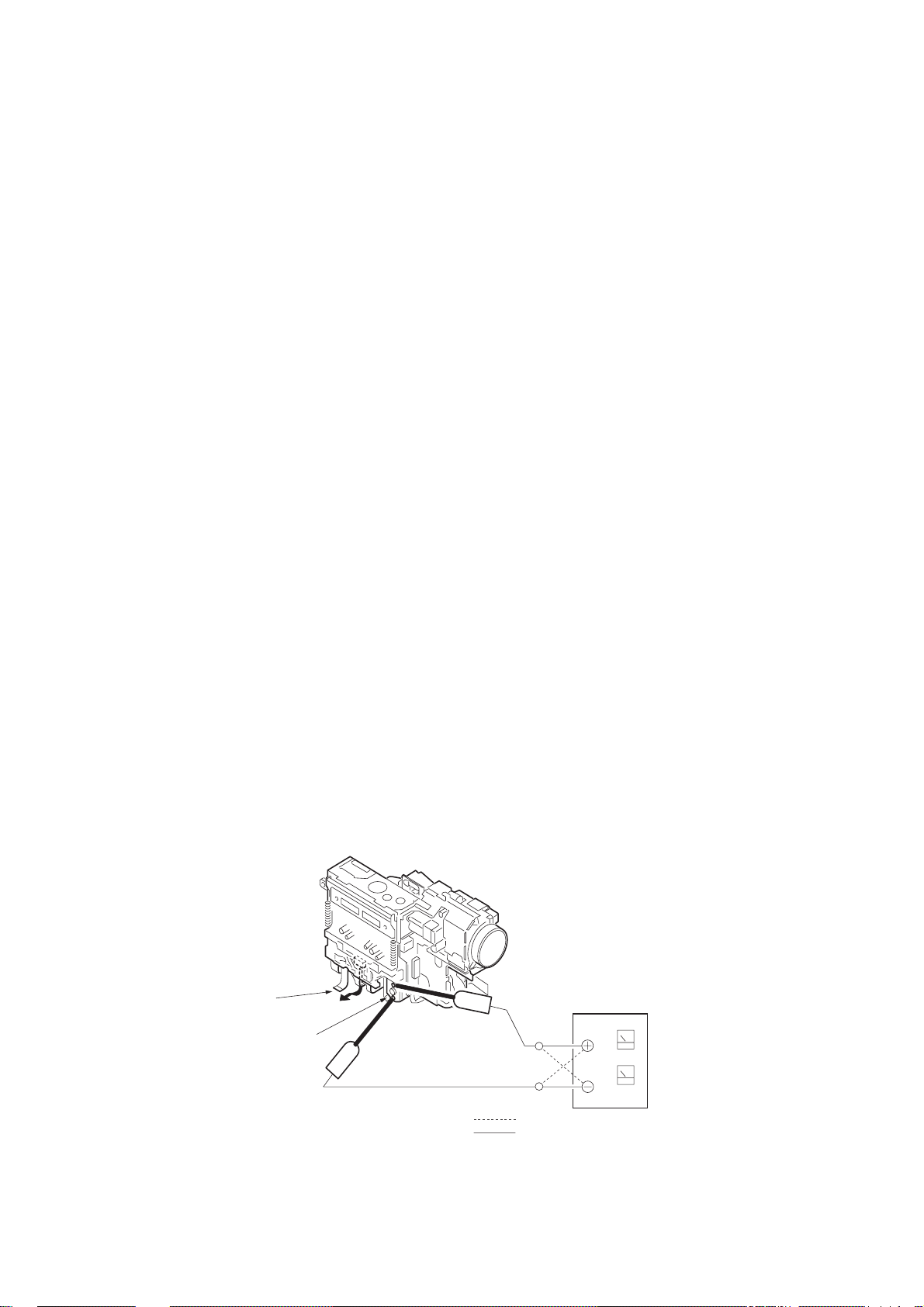
2. HOW TO TAKE A CASSETTE OUT
WHEN THE MAIN POWER CANNOT
BE TURNED ON
Note: To take a cassette out forcibly as follows when the main power
cannot be turned on, remove the cassette lid, cabinet (L) and cabinet
(R). Apply +4.5 V power from an external power supply to the
loading motor, as shown below. Refer to sections 2-1 and 2-2 for
the procedure to remove the cabinet (L) assembly.
Procedure:
1) Disconnect the CN2913 of VI-151 board.
2) Apply +4.5 V directly to the loading motor as shown to drive
the loading motor that ejects a cassette.
Disconnect CN2913
of VI-151 board.
DC power supply (+4.5V
Loading motor
: loading
: unloading
— 6 —
Page 7
DCR-TRV890E/TRV900/TRV900E
Control dial
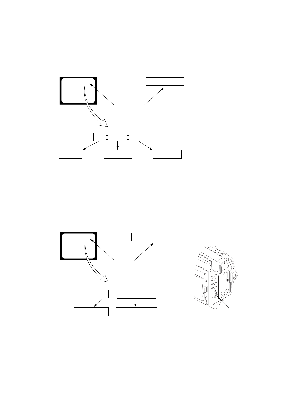
SELF-DIAGNOSIS FUNCTION
1. SELF-DIAGNOSIS FUNCTION
When problems occur while the unit is operating, the self-diagnosis
function starts working, and displays on the viewf inder, LCD screen
or LCD window what to do. This function consists of two display;
self-diagnosis display and service mode display.
Details of the self-diagnosis functions are provided in the Instruction
manual.
Viewfinder or LCD screen LCD window
C : 3 1 : 1 1
Blinks at 3.2Hz
1 1
Repaired by:
C : Corrected by customer
H : Corrected by dealer
E : Corrected by service
engineer
C
Indicates the appropriate
step to be taken.
E.g.
31 ....Reload the tape.
32 ....Turn on power again.
3 1
Block
2. SELF-DIAGNOSIS DISPLA Y
When problems occur while the unit is operating, the counter of the
viewfinder, LCD screen or LCD window consists of an alphabet
and 4-digit numbers, which blinks at 3.2 Hz. This 5-character display
indicates the “repaired by:”, “block” in which the problem occurred,
and “detailed code” of the problem.
C : 3 1 : 11
Detailed Code
Refer to page 8.
Self-diagnosis Code Table.
3. SERVICE MODE DISPLAY
The service mode display shows up to six self-diagnosis codes shown in the past.
3-1. Display Method
While pressing the “STOP” key, set the switch from OFF to “VTR or PLAYER”, and continue pressing the “STOP” key for 5 seconds
continuously. The service mode will be displayed, and the counter will show the backup No. and the 5-character self-diagnosis codes.
Viewfinder or LCD screen
[3] C : 3 1 : 1 1
Lights up
[3]
Backup No.
Order of previous errors
C : 3 1 : 1 1
Self-diagnosis Codes
3-2. Switching of Backup No.
By rotating the control dial, past self-diagnosis codes will be shown in order. The backup No. in the [] indicates the order in which the
problem occurred. (If the number of problems which occurred is less than 6, only the number of problems which occurred will be shown.)
[1] : Occurred first time [4] : Occurred fourth time
[2] : Occurred second time [5] : Occurred fifth time
[3] : Occurred third time [6] : Occurred the last time
LCD window
3 C : 3 1 : 11
3-3. End of Display
Turning OFF the power supply will end the service mode display.
Note: The “self-diagnosis display” data will be backed up by the coin-type lithium battery of CK-80 board BT7200. When this coin-type lithium battery
is removed, the “self-diagnosis display” data will be lost by initialization.
— 7 —
Page 8

4. SELF-DIAGNOSIS CODE T ABLE
Self-diagnosis Code
Block
Function
Repaired by:
C
21
C
22
C
23
C
31
C
31
C
31
C
31
C
31
C
31
C
31
C
31
C
31
C
31
C
31
C
31
C
32
C
32
C
32
C
32
C
32
C
32
C
32
C
32
E
61
E
61
E
62
E
62
Detailed
Code
00
00
00
10
11
20
21
22
23
24
30
40
42
10
11
20
21
22
23
24
30
40
42
00
10
00
01
Symptom/State
Condensation.
Video head is dirty.
Non-standard battery is used.
LOAD direction. Loading does not
complete within specified time
UNLOAD direction. Loading does not
complete within specified time
T reel side tape slacking when unloading
Winding S reel fault when counting the
rest of tape.
T reel fault.
S reel fault.
T reel fault.
FG fault when starting capstan.
FG fault when starting drum.
FG fault during normal drum operations.
LOAD direction loading motor time-
out.
UNLOAD direction loading motor
time-out.
T reel side tape slacking when
unloading.
Winding S reel fault when counting the
rest of tape.
T reel fault.
S reel fault.
T reel fault.
FG fault when starting capstan.
FG fault when starting drum
FG fault during normal drum
operations
Difficult to adjust focus
(Cannot initialize focus.)
Zoom operations fault
(Cannot initialize zoom lens.)
Steadyshot function does not work well.
(With pitch angular velocity sensor output
stopped.)
Steadyshot function does not work well.
(With yaw angular velocity sensor output
stopped.)
Correction
Remove the cassette, and insert it again after one hour.
Clean with the optional cleaning cassette.
Use the info LITHIUM battery.
Load the tape again, and perform operations from the beginning.
Load the tape again, and perform operations from the beginning.
.
Load the tape again, and perform operations from the beginning.
Load the tape again, and perform operations from the beginning.
Load the tape again, and perform operations from the beginning.
Load the tape again, and perform operations from the beginning.
Load the tape again, and perform operations from the beginning.
Load the tape again, and perform operations from the beginning.
Load the tape again, and perform operations from the beginning.
Load the tape again, and perform operations from the beginning.
Remove the battery or power cable, connect, and perform
operations from the beginning.
Remove the battery or power cable, connect, and perform
operations from the beginning.
Remove the battery or power cable, connect, and perform
operations from the beginning.
Remove the battery or power cable, connect, and perform
operations from the beginning.
Remove the battery or power cable, connect, and perform
operations from the beginning.
Remove the battery or power cable, connect, and perform
operations from the beginning.
Remove the battery or power cable, connect, and perform
operations from the beginning.
Remove the battery or power cable, connect, and perform
operations from the beginning.
Remove the battery or power cable, connect, and perform
operations from the beginning.
Remove the battery or power cable, connect, and perform
operations from the beginning.
Inspect the lens block focus reset sensor (Pin !º of CN500 of VC-
208 board) when focusing is performed when the control dial is
rotated in the focus manual mode, and the focus motor drive circuit
(IC500 of VC-208 board) when the focusing is not performed.
Inspect the lens block zoom reset sensor (Pin !™ of CN500 of VC208 board) when zooming is performed when the zoom lens is
operated and the zoom motor drive circuit (IC500 of VC-208 board)
when zooming is not performed.
Inspect pitch angular velocity sensor (SE451 of SE-75 board)
peripheral circuits.
Inspect yaw angular velocity sensor (SE450 of SE-75 board)
peripheral circuits.
— 8 —
Page 9
SECTION 1
GENERAL
DCR-TRV890E/TRV900/TRV900E
This section is extracted from instruction
manual. (DCR-TRV890E/TRV900E model)
1-1
Page 10
1-2
Page 11
1-3
Page 12
1-4
Page 13
1-5
Page 14
1-6
Page 15
1-7
Page 16
1-8
Page 17
1-9
Page 18
1-10
Page 19
1-11
Page 20
1-12
Page 21
1-13
Page 22
1-14
Page 23
1-15
Page 24
1-16
Page 25
1-17
Page 26
1-18
Page 27
1-19
Page 28
1-20
Page 29
1-21
Page 30
1-22
Page 31

1-23
Page 32

1-24
Page 33

1-25
Page 34

1-26
Page 35

1-27
Page 36

1-28
Page 37

1-29
Page 38

1-30
Page 39

1-31
Page 40

1-32
Page 41

1-33
Page 42

1-34
Page 43

1-35
Page 44

1-36
Page 45

1-37
Page 46

1-38
Page 47

1-39
Page 48

1-40
Page 49

1-41
Page 50

1-42
Page 51

1-43
Page 52

1-44
Page 53

1-45
Page 54

1-46E
Page 55

SECTION 2
DISASSEMBLY
NOTE: Follow the disassembly procedure as shown in the flow chart below.
DCR-TRV890E/TRV900/TRV900E
2-1. Cabinet (upper) assembly, Front panel assembly
2-2. Battery panel assembly
2-3. Cabinet (R) assembly, Cabinet (L) assembly
2-4.
SE-75 board
2-4.
Lens assembly
1-5
2-4.
VC-208 board
6-@º
2-4.
VI-151 board
!£-@º
2-4.
Mechanism deck
@¡-@£
@¢-@¶
2-5 JK-163 board
2-6. CK-80 board
2-7. Hinge assembly
2-8. PD-101 board
2-12. MA-333 board
DCR-TRV890E/TRV900/TRV900E
2-10.
ED-48 board
1-4
2-10.
VF-121 board
5-!£
2-11. LB-55 board
2-9. BT terminal board DC-IN connector
NOTE: Follow the disassembly procedure in the numerical order given.
2-1. CABINET (UPPER) ASSEMBLY, FRONT PANEL ASSEMBLY
4
Screw (M2 × 4)
6
Flexible board
CN7207 24P (CK-80 board)
5
FP-17 flexible board
CN7203 6P (CK-80 board)
8
Cabinet (upper) assembly
7
FP-10 flexible board
CN2905 20P (VI-151 board)
3
Screw (M2 × 4)
9
Open the jack cover and
remove the screw (M2 × 4).
!¡
Front panel assembly
(Remove it while being
careful of the claw a.)
a
a
!™
CN7304 26P (MA-333 board)
!º
Two screws (M2 × 4)
FP-12 flexible board
2-1
1
2
Screw (M2 × 4)
Screw (M2 × 4)
Page 56

2-2. BATTERY PANEL ASSEMBLY
9
Cable CN3200 4P (VI-151 board)
1
Screw (M2 × 4)
7
8
Cable 3P, CN3201 3P (VI-151 board)
2
Two screws (M2 × 4)
6
Battery panel assembly
Remove it by opening to a
side a little together with the
cabinet (R) assembly)
FP-18 flexible board CN7210 8P (CK-80 board)
3
Screw (M2 × 4)
4
CPC cover
Cabinet (R) assembly
5
Three screws (M2 × 4)
2-3. CABINET (R) ASSEMBLY, CABINET (L) ASSEMBLY
5
4
Two screws (M2(step))
!¡
Cabinet (L) assembly
Cassette lid
6
Screw
(M2
1-3
Cabinet (R) assembly
4-!¡
Cabinet (L) assembly
7
Screw (M2 × 4)
×
4)
9
Control switch block (FK-4880),
CN2907 18P (VI-151 board)
Mechanism deck, lens assembly
1
FP-9 flexible board
CN2906 60P (VI-151 board)
8
Screw
(M2
×
4)
!º
FP-12 flexible board
CN2902 27P (VI-151 board)
2
FP-13 flexible board
CN761 60P (VC-208 board)
2-2
3
Cabinet (R) assembly
Page 57

2-4. MECHANISM DECK, LENS ASSEMBLY, VC-208, VI-151, SE-75 BOARDS
)
1-5
Lens assembly
6-!º
VC-208 board
!¡-!•
VI-151 board
!ª-@¡
Mechanism deck
@™-@∞
SE-75 board
@¡
Mechanism deck
@§
MD frame assembly
@º
Two screws
(M2 step)
!ª
Screw
(M2 step)
!™
Screw (M2)
!£ a
flexible board (from capstan motor
CN2912 27P (VI-151 board)
!¢ b
flexible board (from loading motor,
S/T reel sensor)
CN2913 27P (VI-151 board)
!∞ c
flexible board (from drum motor)
CN2911 11P (VI-151 board)
!§ d
flexible board (from video head)
CN1810 10P (VI-151 board)
4
Flexible board
CN500 26P (VC-208 board)
3
Flexible board
@∞
SE-75 board
@¢
Two screws (M2 × 4)
@™
FP-14 flexible board
CN450 6P (ED-75 board)
@£
Screw (M2 × 4)
5
SE-75
BOARD
Lens block
2
Two screws
(M2
×
4)
!¶
FP-12 flexible board
VI-151
BOARD
c
d
!•
VI-151
board
!¡
Two
screws
(M2
×
4)
8
FP-8 flexible board
CN900 100P (VC-208 board)
9
FP-8 flexible board
CN2901 100P (VI-151 board)
b
a
VC-208
BOARD
CN351 8P (VC-208 board)
!º
VC-208 board
1
CD-202 board
CN200 40P
(VC-208 board)
7
Three screws (M2 × 3)
6
FP-14 flexible board
CN400 6P (VC-208 board)
CN2902 27P (VI-151 board)
2-5. JK-163 BOARD
1
FP-11 flexible assembly
2-6
JK-163 board
7-!£
Control switch block
(FK-4880)
!¢-@¡
FP-23 flexible board
external connector
(hot shoe)
e
9
Screw (M2 × 4)
!•
Remove the FP-23
flexible board.
!£
Control switch block (FK-4880) flexible board
Remove the
direction of
d
portion in the
b
and remove the
and e portions in the arrow direction
as shown without applying force to the
a
portion of the flexible board.
a
c
c
Shoe retainer
Craw
!¶
While raising the shoe
retainer in order to release
the claw, push the shoe
retainer in the direction of
e
to remove it.
@º
Shoe retainer
!ª
Four screws (M2 × 3)
6
JK-163 board
5
Screw (M2 × 3)
1
FP-11 flexible board
CN7102 39P (JK-163 board)
@¡
External
connector
(hot shoe)
!§
the S-terminal.
Remove
!¡
FK frame
JK-163
BOARD
2-3
b
d
!º
Two tapping
screws (B2
!∞
S-terminal metal plate
!™
Tapping screw (B2 × 4)
8
×
4)
!¢
Two tapping screws (B2 × 4)
4
J-K retaining metal plate
3
Four tapping screws (B2 × 4)
2
FP-23 flexible board CN7101 14P
(JK-163 board)
e
Strap metal plate
7
B2 × 4
Page 58

2-6. CK-80 BOARD
1-6
PM slider assembly
7-!¶
CK-80 board
!•-@¡
Speaker
1
Screw (M2 × 3)
2
PM cover
!™
FP-16 flexible board
CN7202 6P
(CK-80 board)
9
Two screws
(M1.7 × 3)
Insert the craw
into the slider
when re-assembling.
8
Two screws
(M1.7 × 3)
7
Two screws
(M1.7 × 3)
CK-80
BOARD
!¶
Card ejector
(Slide it in the direction
of the arrow.)
!º
CK-80
board
!∞
FP-9 flexible board CN7204 60P
(CK-80 board)
!•
Two screws (M2 × 3)
!ª
Speaker fixing plate
@º
Speaker
@¡
SP folder
!¢
FP-13 flexible board
CN7208 6P
(CK-80 board)
!£
Remove the harness
(CP-81, CP-82).
6
PM slider assembly
!¡
Remove the
harness.
(SP-156)
5
Two screws (M2 × 3)
3
Two screws (M2 × 4)
2-7. LCD PANEL ASSEMBLY, HINGE ASSEMBLY
1-8
9-!¶
!º
LCD hinge lid
9
Three screws
(M2 × 3)
!™
Three screws
(M2 × 3)
LCD panel block
Hinge assembly
!¡
Blind plate
!¶
Hinge cover
(front)
7
Two screws
(M2 × 3)
d
d
!£
Hinge assembly
(Remove it in the direction
of the arrow a.)
!§
Hinge cover (rear)
(Remove it while being
careful of the craw.)
!¢
Screw (M1.7 × 3)
a
5
Remove the
Craws
CP-81 harness.
6
Remove
the CP-82
harness.
4
Stand
PD-101
BOARD
LCD panel assembly
!§
Four screws (M2 × 7)
Rotate it by 90
direction of the arrow
b
2
Screw
(M2 × 4)
8
LCD panel block
°
in the
b.
Rotate it by 90
in the direction
of the arrow c.
C
3
Screw (M2 × 4)
°
Rotate it by 90 ° in the
direction of the arrow d.
!∞
Two screws
(M1.7 × 3)
4
P cabinet (C) assembly
2-4
1
Two screws (M2 × 4)
Page 59

2-8. PD-101 BOARD
1-5
PD-101 board
6-8
FP-19 flexible board
9-!™
LCD panel
9
Cold cathode fluorescent
tube with light-conduction plate
2
Flexible board
6
Panel frame
(Remove it while being
careful of the four craws.)
CN5701 10P
(PD-101 board)
!º
Light-conduction
plate insulation sheet
!¡
LCD module
Craws
!™
P cabinet (M) assembly
3
Flexible board (FP-55)
CN5601 24P
(PD-101 board)
Craws
PD-101
BOARD
4
1
Screw
(M2
×
3)
5
PD-101 board
FP-19 flexible board
CN5805 6P (PD-101 board)
2-9. BT TERMINAL BOARD, DC-IN CONNECTOR
1-3
BT terminal plate
4-6
DC-IN connector
7-!º
FP-18 flexible board
3
BT terminal board
7
Two screws (M2 × 3)
8
FP-19 flexible board
Battery panel assembly
1
6
DC-IN connector
Screw (M2 × 4)
2
Strap metal plate
7
Two tapping
screws (B2 × 5)
!º
9
AL knob
8
AL knob folder
2-5
4
Two tapping screws (B2 × 5)
FP-18 flexible board
5
DC fixing plate
Page 60

2-10.ED-48, VF-121 BOARDS
1-4
ED-48 board
5-8
EVF assembly
9-!£
VF-121 board
!¢-!¶
VF slide base
4
Edit button
3
ED-48
board
1
Four screws
×
3)
(M2
2
FP-17 flexible board
CN7000 6P (ED-48 board)
7
Two screws
×
(M2
4)
5
Four screws (M2 × 4)
6
Slider ground plate
8
EVF assembly
9
CN5001 21P (VF-121 board)
!§
VF click plate
!™
the craw.
FP-10 flexible board
!∞
Slide here.
Release
!¶
VF slide base
!¢
Peel off the cushion.
!£
VF-121 board
!¡
Release the two craws.
!º
FP-20 flexible board
CN5101 30P
(VF-121 board)
2-11.LB-55 BOARD
9
Flexible board
CN5202 16P (LB-55 board)
!£
BL diffusion plate
8
FP-20 flexible board
CN5201 27P
(LB-55 board)
!¢
!™
LCD cushion
3
Two tapping screws (M2 × 4)
!º
VF lens assembly
(Remove it in the direction
of the arrow a.)
!§
LCD cushion 1
!∞
LCD
LCD cushion
6
EVF cabinet (upper)
a
7
Eye cup assembly
4
EVF cabinet
(lower) assembly
1
Four tapping screws
(M1.7 × 5)
5
VF slider assembly
!¡
LB-55 board
2
Two tapping screws (M1.7 × 8)
2-6
Page 61

MA-333
BOARD
FP-21
!¶
Screw (M2 × 3)
1-7
MA-333 board
8-0
FP-22 flexible board (MIC jack)
!¡-!¶
FP-21 flexible board
!£
MF reinforcement plate
!•
FP-21 flexible board
2
FP-21 flexible board
CN7302 10P (MA-333 board)
3
FP-37 flexible board
CN7305 6P (MA-333 board)
6
Cable (MIC)
CN7300 2P (MA-333 board)
5
Cable (MIC)
CN7301 2P (MA-333 board)
1
Sound insulation sheet
!¢
MF retainer
assembly
!§
Tapping screw
(B2
×
5)
!∞
Screw (M2 × 3)
0
Jack retainer
9
Tapping screw
(B2
×
5)
4
Two tapping screws (B2 × 5)
8
MA-333 board
!¡
FP-22 flexible board
(MIC jack)
7
FP-22 flexible board
CN7303 5P (MA-333 board)
!™
Tapping screw
(B2
×
5)
2-12.MA-333 BOARD
2-13.SERVICE POSITION (Mainly for check and voltage measurement)
Firstly, remove the following parts referring to DISASSEMBLY (sections 2-1 to 2-6, 2-10 and 2-12), and connect parts as shown
below.
Control switch block
(FK-4880)
LCD panel
PD-101 board
VF-121
board
When the ED-48 board and LCD display panel are
not needed to connect during check and voltage
measurement, this connection is not necessary.
ED-48 board
a
b
Extension
cable
(J-6082 431-A)
CK-80
BOARD
FP-9
FP-10
LCD display panel
SE-75 board
FP-14
FP-13
a
b
VI-151
BOARD
Base 2
Lens block
VC-208
BOARD
FP-12
CD-202 board
Extension
cable
(J-6082 432-A)
MA-333
board
FP-73
RI-10 board
Base 1: Using a box or the like,
support the lens block,
CD-202 board and
VC-208 board as shown.
Base 2: Using a box or the like,
support the VI-151
board as shown.
Base 1
FP-23
JK-163 board
EVF (LB-55 board, LCD)
Battery case assembly
2-7
AC
adapter
AC IN
Extension cable
(J-6082-433-A)
Mechanism deck
Adjustment remote
commander (RM-95)
Page 62

)
2-14.CIRCUIT BOARDS LOCATION
ED-48
SE-75
(YAW/PITCH SENSOR)
JK-163
(AUDIO/VIDEO IN/OUT)
RI-10
(SIRCS RECEIVER)
(USER CONTROL)
MA-333
(STEREO MIC AMP)
LB-55
(EVF BACK-LIGHT)
VF-121
(COLOR EVF)
CK-80
USER CONTROL,
LCD DRIVE
CD-202
(CCD IMAGER)
PD-101
(RGB DRIVER, TIMING GENERATOR, BACK-LIGHT
VC-208
SAMPLE HOLD & AGC,
CAMERA PROCESSOR,
BASE BAND INPUT,
MOTOR DRIVE, VAP DRIVER,
CARD CONTROL,
PWM CONTROL,
HONEY/PCMCIA CONTROL
VI-151
REC/PB AMP, TIMING GENERATOR, VIDEO INTERFACE,
DCT/IDCT, IR TRANSMITTER, AUDIO PROCESSOR,
HI CONTROL, MECHANISM CONTROL,
DRUM/CAPSTAN MOTOR DRIVE, DC/DC CONVERTER
2-8
Page 63

)
2-15.FLEXIBLE BOARDS LOCATION
FK-4880
(USER CONTROL)
FP-17
FP-23
(S-Y/C IN/OUT)
FP-16
FP-11
FP-13
FP-8
FP-18
(USER CONTROL
For LED
LENS BLOCK
FP-21
(FOCUS)
FP-22
(MIC JACK)
FP-10
FP-19
(USER CONTROL)
FP-20
FP-9
(From CAPSTAN MOTOR)
From LOADING MOTOR,
S/T REEL SENSOR
(From DRUM MOTOR)
FP-12
FP-37
FP-14
(From VIDEO HEAD)
2-9E
Page 64

3-1. OVERALL BLOCK DIAGRAM
SECTION 3
DCR-TRV890E/TRV900/TR V900E
BLOCK DIAGRAMS
3-1 3-2 3-3 3-4
Page 65

DCR-TRV890E/TRV900/TR V900E
3-2. POWER BLOCK DIAGRAM
3-5 3-6 3-7 3-8E
Page 66

PRINTED WIRING BOARDS AND SCHEMATIC DIAGRAMS
4-1. FRAME SCHEMA TIC DIAGRAM-1
SECTION 4
DCR-TRV890E/TRV900/TR V900E
4-1 4-2 4-3 4-4
FRAME SCHEMA TIC DIAGRAM-1
Page 67

DCR-TRV890E/TRV900/TR V900E
FRAME SCHEMA TIC DIAGRAM-2
FRAME SCHEMA TIC DIAGRAM-2
4-5 4-6 4-7 4-8
Page 68

DCR-TRV890E/TRV900/TR V900E
4-2. PRINTED WIRING BOARDS AND SCHEMATIC DIAGRAMS
THIS NOTE IS COMMON FOR WIRING BOARDS AND SCHEMATIC DIAGRAMS
(In addition to this, the necessary note is printed in each block)
DCR-TRV890E/TRV900/TR V900E
(For printed wiring boards)
• b: Pattern from the side which enables seeing.
(The other layers' patterns are not indicated.)
• Through hole is omitted.
• Circled numbers refer to waveforms.
• There are few cases that the part printed on diagram
isn’t mounted in this model.
• Chip parts.
Transistor Diode
C
5
BE
64
2
13
5
46
2
31
45
2
31
12
4
53
3
21321321
(For schematic diagrams)
• All capacitors are in µF unless otherwise noted. pF : µµF.
50V or less are not indicated except for electrolytics and
tantalums.
• Chip resistors are 1/10W unless otherwise noted.
kΩ=1000Ω, MΩ=1000kΩ.
• Caution when replacing chip parts.
New parts must be attached after removal of chip.
Be careful not to heat the minus side of tantalum capacitor, Because it is damaged by the heat.
• Some chip part will be indicated as follows.
Example C541 L452
22U 10UH
TA A 2520
Kinds of capacitor
Temperature characteristics
External dimensions (mm)
• Constants of resistors, capacitors, ICs and etc with XX indicate
that they are not used.
In such cases, the unused circuits may be indicated.
• Parts with ★ differ according to the model/destination.
Refer to the mount table for each function.
• All variable and adjustable resistors have characteristic curve B,
unless otherwise noted.
• Signal name
XEDIT→ EDIT PB/XREC → PB/REC
• 2 : non flammable resistor
• 1 : fusible resistor
• C : panel designation
• A : B+ Line *
• B : B– Line *
• J : IN/OUT direction of (+,–) B LINE. *
• C : adjustment for repair. *
• Circled numbers refer to waveforms. *
*Indicated by the color red.
Note :
The components identified by
mark ! or dotted line with mark
! are critical for safety.
Replace only with part number
specified.
Note :
Les composants identifiés par
une marque ! sont critiques
pour la sécurité.
Ne les remplacer que par une
pièce portant le numéro spécifié.
(Measuring conditions voltage and waveform)
• Voltages and waveforms are measured between the measurement points and ground when camera shoots color bar chart of
pattern box. They are reference values and reference waveforms. *
(VOM of DC 10 MW input impedance is used.).
• Voltage values change depending upon input impedance of VOM
used.)
1. Connection
Pattern box
95 cm
Front side of the lens
2. Adjust the distance so that the output waveform of Fig. a and
the Fig. b can be obtain.
H
Yellow
Cyan
White
Magenta
Green
AABBA=B
Fig. a (Video output terminal output waveform)
Cyan
White
Green
Yellow
Magenta
Fig.b (Picture on monitor TV)
3. • The LINE REC waveform shows the waveform when the color
for signal (video signal) is input from a color bar pattern.
• The LINE OUT waveform shows the waveform when the
signals are connected to the S-VIDEO and VIDEO/AUDIO
jacks but not to other jacks.
When indicating parts by reference number, pleas include
the board name.
Red
Blue
Red
Blue
Electron beam
scanned frame
CRT picture frame
4-9
Page 69

DCR-TRV890E/TRV900/TRV900E
CD-202
CAMERA REC
IC100 1, 2
1
IC101 1, 2
IC102 1, 2
IC100 3, IC101 3
2
IC102 3
IC100 !£, !¢
3
IC101 !£, !¢
IC102 !£, !¢
13.5 MHz
IC100 !™, IC101 !™
4
IC102 !™
BOARD
H
V
8.4Vp-p
22Vp-p
3.0Vp-p
5
Q101 E
6
Q100 E
7
Q102 E
13.5 MHz
H
H
H
H
H
3.0Vp-p
0.6Vp-p
0.6Vp-p
0.5Vp-p
CCD IMAGER
CD-202
4-11 4-12
Page 70

DCR-TRV890E/TRV900/TR V900E
DCR-TRV890E/TRV900/TR V900E
CD-202 (CCD IMAGER) PRINTED WIRING BOARD
— Ref. No. CD-202 Board; 10,000 Series —
CD-202 BOARD
C100 C-5
C101 C-5
C102 F-5
C103 A-5
C104 D-5
C105 F-5
C106 A-5
C107 C-5
C108 C-5
C109 C-5
C110 C-6
C111 A-5
C112 A-6
C113 E-5
C114 A-6
C115 A-5
C116 A-5
C117 F-5
C118 F-5
C119 F-5
C120 E-5
CN100 B-1
IC100 F-7
IC101 C-7
IC102 A-7
L100 C-5
L101 A-5
L102 E-5
Q100 C-6
Q101 F-5
Q102 A-6
R100 C-5
R101 F-5
R102 A-5
R103 C-5
R104 F-5
R105 A-5
4-13 4-14
CCD IMAGER
CD-202
For printed wiring boards
• This board is six-layer print board. However, the patterns of layers two to five have not been included in
the diagram.
• Chip parts
Transistor
C
BE
There are few cases that the part printed on this
diagram isn’t mounted in this model.
CD-202
(CCD IMAGER)
VI-151
REC/PB AMP, TIMING GENERATOR, VIDEO INTERFACE,
DCT/IDCT, IR TRANSMITTER, AUDIO PROCESSOR,
HI CONTROL, MECHANISM CONTROL,
DRUM/CAPSTAN MOTOR DRIVE, DC/DC CONVERTER
VC-208
SAMPLE HOLD & AGC,
CAMERA PROCESSOR,
BASE BAND INPUT,
MOTOR DRIVE, VAP DRIVER,
CARD CONTROL,
PWM CONTROL,
HONEY/PCMCIA CONTROL
Page 71

DCR-TRV890E/TRV900/TR V900E
VC-208 BOARD (SIDE A)
C228 E-7
C234 E-6
C235 E-6
C236 D-7
C237 D-7
C238 E-6
C239 E-5
C252 E-7
C253 E-6
C254 E-5
C255 E-8
C256 E-7
C257 E-7
C258 E-6
C259 E-6
C260 E-6
C300 D-7
C301 C-8
C500 D-5
C501 C-5
C502 C-4
C503 C-4
C504 C-5
C505 C-5
C506 D-5
C507 D-5
C508 D-4
C509 C-5
C510 D-5
C511 C-5
C512 C-5
C514 D-5
C515 D-5
C516 C-4
C517 D-4
C518 C-4
C519 D-5
C520 D-5
C521 C-6
C522 C-6
C523 D-6
C524 D-6
C525 C-6
C526 D-6
C527 C-6
C528 C-6
C530 D-6
C531 D-5
C532 C-3
C533 C-5
C534 C-6
C701 A-1
C703 A-1
C704 A-1
C733 B-2
C734 A-2
C735 C-1
C736 A-1
C737 A-1
C738 B-1
C739 C-1
C740 B-3
C742 C-2
C743 C-3
C752 C-3
C753 C-3
C754 C-5
C760 A-5
C762 B-4
C763 C-5
C764 A-7
C765 A-8
C766 A-8
C767 B-7
C768 B-7
CN200 E-8
CN351 C-3
CN400 A-2
CN500 C-2
CN761 B-1
D500 C-5
D501 D-5
D721 B-2
D722 B-2
FB202 D-7
FB300 C-8
FB301 D-6
FB501 C-4
FB752 C-5
FB754 A-7
IC205 D-8
IC206 D-7
IC207 D-6
IC300 C-7
IC500 C-4
IC501 C-5
IC502 C-6
IC752 B-3
IC756 B-5
IC757 B-6
IC758 B-8
L201 E-6
L500 D-4
L501 C-4
L503 D-5
L721 B-2
L722 B-2
L723 B-1
L723 C-2
L724 B-1
L725 B-3
L726 C-1
L727 C-2
L751 C-4
L752 A-8
Q500 C-4
Q501 C-5
Q502 C-5
Q503 D-5
Q504 C-6
Q505 C-4
Q701 A-1
Q702 A-3
Q721 B-2
Q722 B-2
R201 D-7
R204 D-5
R205 D-6
R325 B-8
R326 B-8
R500 C-3
R501 C-4
R502 C-5
R503 C-3
R504 C-5
R505 C-5
R506 C-5
R507 C-5
R508 C-5
R509 C-5
R510 D-5
R511 C-5
R512 D-5
R513 D-5
R514 C-5
R515 D-5
R516 D-5
R517 D-5
R518 C-5
R519 C-5
R520 C-5
R521 C-5
R522 C-5
R523 D-5
R524 D-6
R525 C-6
R526 C-6
R528 C-6
R529 C-6
R530 D-6
R531 C-6
R532 D-6
R533 D-6
R534 C-6
R535 D-6
R536 D-6
R537 D-6
R538 C-6
R539 C-6
R540 C-6
R541 C-6
R542 C-6
R543 C-3
R544 D-5
R545 C-4
R701 A-1
R702 A-1
R703 A-1
R704 A-1
R734 B-2
R735 B-2
R765 B-9
R766 B-9
R767 B-9
R768 B-8
R769 B-8
R770 B-8
R771 B-8
R772 B-8
R773 A-8
R774 A-8
R775 A-8
R776 A-8
R777 A-8
R778 A-9
R779 A-9
R780 A-9
R788 B-6
R789 A-7
R790 A-7
R791 B-6
R792 A-6
R800 A-8
R801 B-8
R802 B-6
R803 B-6
R807 C-6
R808 C-4
R810 C-4
R811 C-4
R900 B-5
R901 B-5
R902 B-5
R903 B-5
R904 B-5
R905 B-5
R906 B-5
R907 B-5
R908 B-5
R909 B-5
R910 B-5
R919 B-6
VC-208 (SAMPLE HOLD & AGC, CAMERA PROCESSOR, BASE BAND INPUT, MOTOR DRIVE, VAP DRIVER, CARD CONTROL, PWM CONTROL, HONEY, PCMCIA CONTROL) PRINTED WIRING BOARD
— Ref. No. VC-208 Board; 10,000 Series —
For printed wiring boards
• This board is six-layer print board. However, the patterns of layers two to five have not been included in
the diagram.
• Chip parts
Transistor Diode
C
BE
5
64
2
13
3
21
There are few cases that the part printed on this
diagram isn’t mounted in this model.
CD-202
(CCD IMAGER)
VC-208
SAMPLE HOLD & AGC,
CAMERA PROCESSOR,
BASE BAND INPUT,
MOTOR DRIVE, VAP DRIVER,
CARD CONTROL,
PWM CONTROL,
HONEY/PCMCIA CONTROL
VI-151
REC/PB AMP, TIMING GENERATOR, VIDEO INTERFACE,
DCT/IDCT, IR TRANSMITTER, AUDIO PROCESSOR,
HI CONTROL, MECHANISM CONTROL,
DRUM/CAPSTAN MOTOR DRIVE, DC/DC CONVERTER
CAMERA PROCESS & CNT, S/H &AGC, BASE BAND INPUT, LENS DRIVER, VAP SENSOR, FLASH DD/CNT, VAP DRIVER
VC-208
4-17 4-18
Page 72

VC-208 (SAMPLE HOLD & AGC, CAMERA PROCESSOR, BASE BAND INPUT, MOTOR DRIVE, VAP DRIVER, CARD CONTROL, PWM CONTROL, HONEY, PCMCIA CONTROL) PRINTED WIRING BOARD
— Ref. No. VC-208 Board; 10,000 Series —
VC-208 BOARD (SIDE B)
C201 E-13
C202 E-13
C203 E-13
C204 E-12
C205 E-12
C206 E-12
C207 D-12
C208 D-12
C209 D-12
C211 D-13
C212 D-12
C213 D-12
C214 D-13
C215 D-12
C216 D-12
C216 E-11
C217 D-13
C218 D-13
C219 D-12
C220 D-12
C221 D-12
C222 D-14
C227 D-11
C229 E-11
C230 E-11
C231 E-11
C232 D-12
C233 D-12
C240 E-13
C241 E-12
C242 E-12
C243 D-12
C244 E-12
C245 D-12
C246 D-12
C247 E-11
C248 D-11
C249 D-11
C250 D-12
C261 D-11
C262 D-11
C302 C-11
C303 C-12
C305 A-10
C306 A-10
C307 A-10
C308 C-12
C309 D-12
C310 A-10
C311 C-18
C351 D-15
C353 D-15
C354 D-15
C355 D-15
C357 C-15
C358 C-14
C359 C-14
C360 D-14
C361 C-14
C362 C-14
C368 C-12
C370 D-13
C371 D-13
C372 D-13
C373 C-13
C374 C-13
C375 C-13
C376 C-14
C377 C-14
C379 D-14
C380 C-13
C381 D-14
C382 D-15
C383 D-15
C400 B-12
C401 B-13
C402 A-13
C403 B-12
C404 B-12
C405 B-12
C406 B-12
C407 B-12
C408 A-13
C409 A-12
C410 A-12
C411 A-12
C412 B-13
C413 B-12
C414 B-12
C415 B-12
C702 B-17
C705 A-18
C721 B-18
C722 B-17
C723 B-18
C724 B-18
C725 B-18
C726 B-17
C727 B-18
C728 B-18
C729 B-18
C730 B-18
C731 C-18
C732 C-17
C744 B-17
C751 B-13
C755 C-13
C756 B-14
C757 B-14
C758 C-14
C759 B-15
C761 A-13
C769 C-12
C770 C-12
C771 C-12
C772 A-14
C1200 B-16
C1201 B-16
C1202 B-16
C1203 B-17
C1204 A-16
C1205 B-16
C1206 A-15
C1207 B-16
C1208 B-16
C1209 A-16
C1210 B-16
C1211 A-16
C1212 B-14
C1213 A-15
C1214 A-15
C1215 B-16
C1216 A-15
C1217 A-15
C1218 A-15
C1219 A-16
C1220 A-16
C1221 A-15
C1222 A-15
C1223 A-16
C1224 B-16
C1225 B-15
C1226 B-16
C1227 B-16
C1228 B-16
C1229 A-16
C1230 B-16
C1231 B-15
C1232 B-14
C1233 B-15
C1234 B-15
C1235 C-15
CN900 C-17
D204 E-11
D723 C-18
D724 C-18
D1200 C-16
D1201 C-15
FB200 D-12
FB201 D-11
FB203 E-13
FB204 E-14
IC203 D-13
IC204 D-11
IC208 D-14
IC301 C-11
IC302 B-11
IC305 C-11
IC351 C-15
IC352 C-15
IC354 C-13
IC355 C-13
IC356 C-14
IC357 D-14
IC400 B-12
IC701 A-17
IC721 B-18
IC722 B-17
IC751 B-13
IC753 C-13
IC754 A-14
IC755 A-13
IC759 C-12
IC760 A-14
IC1200 B-15
L200 D-13
L300 C-11
L301 D-12
L351 C-15
L352 D-14
L400 C-12
L754 C-15
L1200 A-16
L1201 B-17
L1202 C-16
L1203 A-16
L1204 B-16
L1205 B-14
Q200 E-13
Q201 E-13
Q301 B-12
Q351 C-14
Q352 D-14
Q353 D-15
Q354 C-15
Q727 B-18
Q751 C-13
Q752 C-14
Q753 B-14
Q754 C-14
Q755 C-12
Q1200 A-16
Q1201 B-16
Q1202 B-16
Q1203 A-16
Q1204 A-16
Q1205 B-16
Q1206 B-16
Q1207 A-15
Q1208 C-17
Q1209 B-16
R200 D-11
R202 E-11
R203 D-11
R207 E-12
R208 E-12
R209 D-12
R210 E-12
R211 D-12
R212 D-12
R213 E-11
R214 D-11
R215 D-11
R216 D-12
R217 E-12
R218 D-12
R219 D-13
R220 D-13
R221 D-14
R222 D-12
R223 D-12
R224 D-12
R225 D-12
R226 D-12
R227 D-12
R235 E-12
R236 E-12
R237 E-13
R300 B-11
R301 B-12
R302 B-12
R303 C-11
R304 B-11
R305 B-11
R306 B-11
R307 B-11
R308 B-11
R309 C-11
R311 B-11
R314 A-10
R316 A-10
R317 A-10
R318 B-10
R319 B-12
R320 B-10
R327 A-11
R328 A-11
R329 A-11
R330 A-11
R331 B-10
R332 A-11
R333 A-11
R334 A-11
R335 A-11
R336 A-11
R350 C-13
R353 D-14
R354 D-14
R355 D-14
R356 D-14
R357 C-15
R358 D-15
R359 C-15
R360 D-15
R361 D-15
R362 C-15
R363 D-15
R364 C-15
R365 D-15
R366 D-15
R367 D-14
R368 D-14
R369 C-14
R370 C-14
R371 C-14
R372 C-14
R373 C-14
R374 C-13
R375 D-13
R376 D-14
R377 C-13
R378 D-13
R379 D-13
R380 C-13
R381 C-13
R382 C-13
R383 C-13
R384 D-13
R385 D-13
R386 D-13
R387 C-14
R388 C-14
R389 D-16
R390 C-16
R391 D-15
R392 D-15
R393 C-14
R394 C-14
R395 D-14
R396 D-13
R400 B-12
R401 B-13
R402 B-13
R403 B-12
R404 B-12
R405 B-12
R406 B-12
R407 B-13
R408 B-12
R409 B-12
R721 B-18
R722 B-18
R723 B-18
R724 B-17
R725 B-18
R726 C-18
R727 B-17
R728 B-18
R729 B-18
R730 B-18
R731 B-17
R732 B-17
R733 B-17
R740 C-18
R741 B-18
R742 C-18
R743 C-18
R744 C-18
R745 C-17
R751 C-13
R752 C-13
R754 C-13
R755 C-14
R756 B-14
R757 B-14
R758 B-14
R759 B-14
R760 A-14
R761 A-14
R762 A-13
R763 C-14
R764 B-14
R781 A-13
R782 A-13
R783 A-13
R784 A-13
R785 A-13
R786 A-13
R787 A-13
R793 A-13
R794 C-12
R795 C-12
R796 C-12
R797 C-12
R804 A-14
R805 A-14
R806 A-14
R809 C-12
R911 B-15
R912 C-15
R913 B-15
R914 C-15
R915 B-15
R916 C-15
R917 B-15
R918 C-15
R920 C-17
R921 C-17
R1202 B-16
R1203 B-16
R1204 B-17
R1205 A-15
R1206 A-16
R1207 B-16
R1208 B-16
R1209 B-16
R1210 A-16
R1211 A-16
R1212 B-16
R1213 B-16
R1214 A-15
R1216 B-16
R1217 A-15
R1218 B-16
R1219 A-15
R1266 B-15
R1267 B-16
R1268 B-16
R1269 B-16
R1270 B-15
R1271 C-15
X1200 C-16
X200 E-11
X300 C-11
X751 B-14
DCR-TRV890E/TRV900/TR V900E
DCR-TRV890E/TRV900/TR V900E
4-19 4-20
CAMERA PROCESS & CNT, S/H &AGC, BASE BAND INPUT, LENS DRIVER, VAP SENSOR, FLASH DD/CNT, VAP DRIVER
VC-208
Page 73

DCR-TRV890E/TRV900/TR V900E
DCR-TRV890E/TRV900/TRV900E
For schematic diagram
• Refer to page 4-17 for printed wiring board.
VC-208
1
CAMERA REC
2
CAMERA REC
3
CAMERA REC
4
CAMERA REC
BOARD (1/7)
IC203 @•, @ª
H
IC203 #¡, #™
H
IC203 #¢, #∞
H
IC203 5
6
0.6Vp-p
0.5Vp-p
0.6Vp-p
IC203 9
CAMERA REC
7
IC204 #¡
CAMERA REC
8
IC204 $¶
CAMERA REC/PB
9
IC205 1 – 5 , 8 – !™
IC206 1 – 5 , 8 – !™
IC207 1 – 5 , 8 – !™
CAMERA REC
H
27.0 MHz
13.5 MHz
0.34Vp-p
3.4Vp-p
3.0Vp-p
H
5
IC203 7
CAMERA REC
H
0.28Vp-p
0.34Vp-p
74 nsec
2.8Vp-p
SAMPLE HOLD & AGC
VC-208 (1/7)
4-24 4-25 4-26
Page 74

For schematic diagram
• Refer to page 4-17 for printed wiring board.
DCR-TRV890E/TRV900/TR V900E
DCR-TRV890E/TRV900/TR V900E
VC-208
!º
CAMERA REC/PB
!¡
CAMERA REC/PB
BOARD (2/7)
IC300 &¶
13.5MHz
IC302 $º
20.0MHz
3.0Vp-p
2.8Vp-p
4-27 4-28 4-29
CAMERA PROCESSOR
VC-208 (2/7)
Page 75

DCR-TRV890E/TRV900/TR V900E
DCR-TRV890E/TRV900/TRV900E
For schematic diagram
• Refer to page 4-17 for printed wiring board.
VC-208
!™
LINE REC
!™
CAMERA REC/PB
!£
LINE REC
!£
CAMERA REC/PB
BOARD (3/7)
IC1200 @∞
H
IC1200 @∞
H
IC1200 #£
H
IC1200 #£
0.44Vp-p
1.0Vp-p
0.5Vp-p
H
!¢
IC1200 #¢
LINE REC
!¢
IC1200 #¢
CAMERA REC/PB
IC1200 $¢
!∞
LINE REC
!§
IC1200 ^¡ – ^•
CAMERA REC/PB,
LINE REC
H
H
40.5MHz
1.5Vp-p
0.44Vp-p
2.0Vp-p
3.0Vp-p
4-31
74 nsec
2.8Vp-p
BASE BAND INPUT
VC-208 (3/7)
4-32 4-33 4-34
Page 76

For schematic diagram
• Refer to page 4-17 for printed wiring board.
DCR-TRV890E/TRV900/TR V900E
DCR-TRV890E/TRV900/TR V900E
4-35 4-36
MOTOR DRIVE
VC-208 (4/7)
Page 77

DCR-TRV890E/TRV900/TR V900E
)
SE-75 (Y AW/PITCH SENSOR) PRINTED WIRING BOARD
— Ref. No. SE-75 Board; 10,000 Series —
SE-75 BOARD
C450 B-2
C451 A-2
CN450 A-2
L450 B-1
SE450 B-2
SE451 C-1
For schematic diagram
• Refer to page 4-17 for printed wiring board of VC-208.
For printed wiring boards
• This board is six-layer print board. However, the patterns of layers two to five have not been included in
the diagram.
There are few cases that the part printed on this
diagram isn’t mounted in this model.
LB-55
(EVF BACK-LIGHT)
VF-121
(COLOR EVF)
ED-48
(USER CONTROL)
SE-75
(YAW/PITCH SENSOR)
JK-163
(AUDIO/VIDEO IN/OUT)
RI-10
(SIRCS RECEIVER)
MA-333
(STEREO MIC AMP)
CK-80
USER CONTROL,
LCD DRIVE
PD-101
(RGB DRIVER, TIMING GENERATOR, BACK-LIGHT
VAP DRIVER
VC-208 (5/7)
YAW/PITCH SENSOR
/
SE-75
4-39 4-40 4-41 4-42
Page 78

For schematic diagram
• Refer to page 4-17 for printed wiring board.
DCR-TRV890E/TRV900/TR V900E
VC-208 BOARD (6/7)
CAMERA REC/PB
!¶ IC722 !º
2.3µsec
0.8Vp-p
4-43 4-44 4-45 4-46
CARD CONTROL, PWM CONTROL
VC-208 (6/7)
Page 79

DCR-TRV890E/TRV900/TR V900E
For schematic diagram
• Refer to page 4-17 for printed wiring board.
HONEY, PCMCIA CONTROL
VC-208 (7/7)
4-47 4-48 4-49 4-50
VC-208
!•
CAMERA REC/PB
BOARD (7/7)
IC751 &¶
6.85MHz
3.8Vp-p
Page 80

For schematic diagram
• Refer to page 4-91 for printed wiring board.
DCR-TRV890E/TRV900/TR V900E
VI-151 BOARD (1/10)
1 IC1816 1, 2, 6, 7
CAMERA REC
6.8msec
3.5Vp-p
2 IC1816 !¡, !™
CAMERA REC
6.8msec
2.0Vp-p
3 IC1816 @¶ PB
0.35Vp-p
6.8msec
4 IC1816 $º
CAMERA REC/PB
41.7MHz
5 IC1816 $™
CAMERA REC
25nsec
6 IC1814 !£ PB
41.85MHz
7 IC1814 !∞ – @º PB
25nsec
2.3Vp-p
2.2Vp-p
2.0Vp-p
2.2Vp-p
8 IC1814 #¡
CAMERA REC/PB
6.8msec
4-51 4-52 4-53
2.6Vp-p
REC/PB AMP
VI-151 (1/10)
Page 81

DCR-TRV890E/TRV900/TR V900E
DCR-TRV890E/TRV900/TRV900E
For schematic diagram
• Refer to page 4-91 for printed wiring board.
VI-151
CAMERA REC
9
BOARD (2/10)
IC1900 $¡
13.5MHz
3.2Vp-p
TIMING GENERA TOR
VI-151 (2/10)
4-55 4-56
Page 82

For schematic diagram
• Refer to page 4-91 for printed wiring board.
DCR-TRV890E/TRV900/TR V900E
DCR-TRV890E/TRV900/TR V900E
VI-151
!º
CAMERA REC
!º
!¡
CAMERA REC
!¡
BOARD (3/10)
Q1500 E
H
Q1500 E LINE REC
Q1501 E
H
Q1501 E LINE REC
0.22Vp-p
0.3Vp-p
H
0.2Vp-p
H
!™
Q1502 E
CAMERA REC
H
!™
Q1502 E LINE REC
H
0.3Vp-p
0.34Vp-p
0.38Vp-p
4-57 4-58 4-59
VIDEO INTERFACE
VI-151 (3/10)
Page 83

DCR-TRV890E/TRV900/TR V900E
DCR-TRV890E/TRV900/TRV900E
For schematic diagram
• Refer to page 4-91 for printed wiring board.
VI-151 BOARD (4/10)
CAMERA REC/PB
!£ IC1600 !¢ (R1627)
24.58MHz
2.6Vp-p
DCT/IDCT
VI-151 (4/10)
4-62 4-63 4-64
Page 84

For schematic diagram
• Refer to page 4-91 for printed wiring board.
DCR-TRV890E/TRV900/TR V900E
DCR-TRV890E/TRV900/TR V900E
VI-151
!¢
LINE REC/PB (IR ON)
82nsec
!∞
!∞
!§
CAMERA REC/PB
BOARD (5/10)
IC1403 @™
IC1403 $¡ PB
H
IC1403 $¡ LINE REC
H
IC1402 @∞
0.8Vp-p
0.5Vp-p
0.5Vp-p
H
!¶
IC1402 @ª
CAMERA REC/PB
H
!•
IC1402 7
CAMERA REC/PB
H
!ª
IC1402 !™
CAMERA REC/PB
H
@º
IC1402 !§
CAMERA REC/PB
0.4Vp-p
0.26Vp-p
2.0Vp-p
1.2Vp-p
4-65 4-66
IR TRANSMITTER
VI-151 (5/10)
H
1.7Vp-p
4-67
Page 85

DCR-TRV890E/TRV900/TR V900E
For schematic diagram
• Refer to page 4-91 for printed wiring board.
AUDIO PROCESSOR
VI-151 (6/10)
4-68 4-69 4-70
Page 86

For schematic diagram
• Refer to page 4-91 for printed wiring board.
DCR-TRV890E/TRV900/TR V900E
VI-151
CAMERA REC/PB
@¡
@™
(X2201, R2262)
BOARD (7/10)
IC2204 $º (R2300)
20.0MHz
IC2204 %£
32.767kHz
3.0Vp-p
3.0Vp-p
4-71 4-72 4-73 4-74
HI CONTROL
VI-151 (7/10)
Page 87

DCR-TRV890E/TRV900/TR V900E
DCR-TRV890E/TRV900/TRV900E
For schematic diagram
• Refer to page 4-91 for printed wiring board.
VI-151 BOARD (8/10)
CAMERA REC/PB
@£ IC2401 1 (X2400)
20.0MHz
2.5Vp-p
4-76
MECHANISM CONTROL
VI-151 (8/10)
4-77 4-78
Page 88

For schematic diagram
• Refer to page 4-91 for printed wiring board.
• Refer to page 4-87 for FP-594 flexible board.
DCR-TRV890E/TRV900/TR V900E
VI-151
CAMERA REC/PB
BOARD (9/10)
DCR-TRV890E/TRV900/TR V900E
@¢ IC2503 4
6.7msec
@∞ IC2503 @™, @£, @¢
1.1msec
@§ IC2503 @∞, @§, @¶
1.1msec
@¶ IC2503 $∞
#º IC2503 ^º
2.6Vp-p
#¡ IC2503 ^£
0.1Vp-p
1.1msec
#™ IC2504 !¶
2.3Vp-p
0.92msec
#£ IC2504 #¡, #£, #¢
1.1msec
900kHz
2.8Vp-p
0.23Vp-p
2.8Vp-p
0.56sec
@• IC2503 $•
0.76sec
@ª IC2503 %¢
3µsec
2.7Vp-p
#¢ IC2505 2, !•, @£
2.7Vp-p
2.8Vp-p
80msec
1.1msec
0.6Vp-p
2.2Vp-p
4-79 4-80 4-81 4-82
VI-151 (9/10)
DRUM/CAPST AN MOTOR DRIVE
Page 89

DCR-TRV890E/TRV900/TR V900E
For schematic diagram
• Refer to page 4-91 for printed wiring board.
DC/DC CONVERTER
VI-151 (10/10)
4-83 4-84 4-85 4-86
Page 90

FP-594 (LOADING MOTOR, S/T REEL SENSOR) PRINTED WIRING BOARD
— Ref. No.: FP-594 Board; 9,000 Series —
FP-594
BOARD
DCR-TRV890E/TRV900/TR V900E
M
LOADING
Q901
TAPE END
M902
MOTOR
DEW
SENSOR
S903
MODE SW
Q902
TAP E TOP
H901
S REEL
SENSOR
For printed wiring boards
• Refer to page 4-82 for FP-594 board schematic diagram.
S901
C IN
H902
T REEL
SENSOR
D901
TAPE
LED
S902
REC.P
CN901
MIC SW
4-87 4-88 4-89
FP-594
LOADING MOTOR, S/T REEL SENSOR
USER CONTROL
FK-4880
Page 91

DCR-TRV890E/TRV900/TR V900E
For printed wiring boards
• This board is six-layer print board. However, the patterns of layers two to five have not been included in
the diagram.
• Chip parts
Transistor Diode
C
BE
5
64
2
13
3
21
42
31
There are few cases that the part printed on this
diagram isn’t mounted in this model.
CD-202
(CCD IMAGER)
VC-208
SAMPLE HOLD & AGC,
CAMERA PROCESSOR,
BASE BAND INPUT,
MOTOR DRIVE, VAP DRIVER,
CARD CONTROL,
PWM CONTROL,
HONEY/PCMCIA CONTROL
VI-151
REC/PB AMP, TIMING GENERATOR, VIDEO INTERFACE,
DCT/IDCT, IR TRANSMITTER, AUDIO PROCESSOR,
HI CONTROL, MECHANISM CONTROL,
DRUM/CAPSTAN MOTOR DRIVE, DC/DC CONVERTER
VIDEO IF , VIDEO I/O & IR, SYSTEM/SER VO CONTROL, AUDIO, POWER
VI-151
VI-151 BOARD (SIDE A)
C1401 A-3
C1402 A-3
C1404 A-2
C1405 A-2
C1409 B-3
C1418 A-2
C1422 B-2
C1423 B-1
C1433 A-2
C1434 A-1
C1436 A-2
C1438 B-2
C1439 A-2
C1449 B-2
C1450 A-3
C1451 A-3
C1452 A-1
C1503 B-2
C1506 B-3
C1507 C-2
C1512 B-2
C1513 B-2
C1600 A-4
C1601 A-4
C1602 A-4
C1603 A-4
C1606 A-3
C1607 A-3
C1612 A-1
C1613 A-4
C1614 B-3
C1615 A-4
C1617 A-4
C1621 A-4
C1623 A-1
C1901 C-6
C1902 A-6
C1903 B-6
C1904 C-5
C1908 A-6
C1909 A-5
C1910 A-6
C1914 B-5
C1915 B-5
C1933 B-5
C2018 C-1
C2029 C-1
C2033 C-1
C2042 C-1
C2043 B-1
C2044 C-1
C2045 B-1
C2046 C-1
C2047 B-1
C2048 C-1
C2049 B-1
C2050 B-1
C2051 B-1
C2053 C-2
C2400 C-5
C2402 D-5
C2403 D-6
C2405 D-6
C2408 C-5
C2409 D-6
C2410 D-6
C2500 B-9
C2507 B-8
C2565 B-8
C2566 B-8
C2569 B-6
C2570 B-8
C2572 B-8
C2573 B-9
C2574 B-7
C2575 B-8
C2576 B-6
C2577 B-7
C2579 B-6
C2582 B-8
C2583 B-8
C2585 B-8
C2586 B-8
C2587 B-8
C2588 B-8
C2589 B-7
C3205 E-9
C3221 C-7
C3236 E-8
C3237 C-7
C3244 C-7
C3245 E-7
C3246 E-7
C3248 E-8
C3249 E-8
C3255 E-9
C3260 D-7
C3262 D-7
C3269 D-7
C3272 A-9
C3273 A-9
CN1810 A-5
CN2901 C-2
CN2903 A-1
CN2904 D-9
CN2905 F-6
CN2906 F-8
CN2911 A-6
CN2912 A-8
CN2913 A-7
CN3200 B-9
CN3201 C-9
D1600 A-4
D3204 C-8
D3205 C-8
D3208 E-7
D3213 E-7
D3216 E-8
D3217 E-8
D3225 C-7
D3226 C-7
D3227 C-7
IC1402 A-2
IC1501 B-3
IC1600 A-3
IC1601 B-4
IC1900 B-6
IC2002 C-2
IC2401 C-6
IC2404 C-4
IC2504 B-8
IC2505 B-7
L1400 A-2
L1500 C-2
L1501 B-2
L1601 A-4
L1602 A-1
L1603 A-4
L2400 C-5
L2512 B-7
L3200 D-9
L3201 E-9
L3202 E-7
L3203 D-9
L3204 D-8
L3205 D-8
L3206 E-8
L3207 D-7
L3208 E-8
L3209 D-8
L3214 E-8
L3215 E-8
L3216 E-8
L3217 E-8
LF3200 C-8
PS3200 C-9
PS3201 C-9
PS3202 C-9
PS3203 C-9
PS3204 C-9
PS3205 C-9
PS3206 C-9
Q1402 A-1
Q1403 A-1
Q1405 B-1
Q1406 A-2
Q1500 B-1
Q1501 B-2
Q1502 B-2
Q1503 B-2
Q2507 B-8
Q3203 C-8
Q3204 C-8
Q3205 C-8
Q3206 C-8
Q3215 C-7
Q3216 C-7
Q3217 C-7
Q3219 C-7
Q3225 C-7
Q3226 C-7
Q3227 E-9
Q3231 E-9
Q3234 C-7
Q3235 E-7
Q3236 D-7
Q3238 E-7
Q3239 D-7
Q3240 D-7
Q3241 D-7
R1414 B-2
R1418 A-2
R1419 B-2
R1421 B-2
R1425 B-1
R1426 B-1
R1430 A-1
R1432 B-2
R1433 A-1
R1434 B-1
R1438 A-1
R1439 B-1
R1440 A-1
R1445 A-1
R1446 B-1
R1447 B-1
R1453 B-2
R1454 B-2
R1455 A-2
R1507 B-1
R1508 B-2
R1509 B-1
R1510 B-2
R1511 B-2
R1512 B-2
R1513 B-3
R1514 B-2
R1515 B-2
R1516 B-3
R1517 B-2
R1518 B-2
R1519 C-2
R1521 B-2
R1522 B-3
R1618 A-4
R1619 A-4
R1620 A-3
R1621 A-4
R1622 A-4
R1623 B-3
R1624 A-4
R1625 A-4
R1626 A-3
R1627 A-3
R1628 B-3
R1629 C-5
R1629 C-5
R1689 A-4
R1909 A-5
R1938 B-6
R1939 B-5
R1940 B-5
R1941 B-5
R1942 A-6
R1943 A-5
R1944 A-6
R1945 C-6
R1946 A-6
R2050 C-1
R2051 C-1
R2052 C-1
R2053 C-1
R2401 C-5
R2402 C-4
R2405 C-5
R2406 D-5
R2407 C-5
R2408 C-5
R2409 C-5
R2410 C-5
R2411 C-5
R2415 C-6
R2416 C-6
R2417 C-6
R2418 C-6
R2419 C-6
R2420 C-6
R2421 C-6
R2422 C-6
R2423 C-6
R2424 C-6
R2425 D-6
R2426 D-6
R2427 C-6
R2428 C-6
R2429 D-6
R2430 D-6
R2432 D-6
R2433 C-5
R2434 D-6
R2436 D-6
R2439 C-6
R2440 C-6
R2441 C-6
R2442 D-6
R2445 D-6
R2505 B-9
R2506 B-8
R2507 B-8
R2508 B-8
R2511 B-8
R2517 B-7
R2530 B-8
R2531 A-7
R2532 A-7
R2533 A-8
R2534 B-8
R2569 B-8
R2572 B-8
R2574 A-7
R2575 B-7
R2576 A-7
R2577 B-7
R2579 B-8
R2582 B-8
R2583 B-8
R2585 B-8
R2587 B-8
R2599 A-8
R2903 F-7
R2904 F-7
R2906 F-7
R2907 F-7
R3203 C-8
R3205 C-8
R3206 C-8
R3208 C-8
R3210 E-9
R3211 D-9
R3215 E-9
R3216 E-7
R3246 D-9
R3257 C-7
R3258 C-7
R3259 C-7
R3260 C-7
R3261 C-7
R3262 C-7
R3264 E-9
R3268 E-9
R3270 E-9
R3272 D-7
R3274 E-7
R3276 D-7
R3277 E-7
R3283 D-7
R3284 D-7
R3285 D-7
R3286 D-7
R3287 D-7
R3299 D-7
R3300 C-7
R3302 C-7
T3200 D-8
T3201 E-7
X1600 A-3
X2400 D-6
VI-151 (REC/PB AMP, TIMING GENERA T OR, VIDEO INTERF ACE, DCT/IDCT, IR TRANSMITTER, AUDIO PROCESSOR,
HI CONTROL, MECHANISM CONTROL, DRUM/CAPST AN MOTOR DRIVE, DC/DC CONVERTER) PRINTED WIRING BOARD
— Ref. No. VI-151 Board; 10,000 Series —
4-91 4-92
Page 92

DCR-TRV890E/TRV900/TR V900E
VI-151 (REC/PB AMP, TIMING GENERA T OR, VIDEO INTERF ACE, DCT/IDCT, IR TRANSMITTER, AUDIO PROCESSOR,
HI CONTROL, MECHANISM CONTROL, DRUM/CAPST AN MOTOR DRIVE, DC/DC CONVERTER) PRINTED WIRING BOARD
— Ref. No. VI-151 Board; 10,000 Series —
VI-151 BOARD (SIDE B)
C1400 A-17
C1403 A-18
C1406 A-18
C1407 B-18
C1410 B-18
C1411 A-17
C1412 A-17
C1413 B-18
C1414 A-18
C1415 B-17
C1416 C-17
C1417 B-18
C1419 A-17
C1420 B-18
C1421 B-17
C1424 B-17
C1425 B-17
C1426 B-17
C1427 A-17
C1428 C-17
C1429 C-17
C1430 A-17
C1431 B-17
C1432 C-17
C1435 C-17
C1437 B-17
C1440 B-17
C1441 B-17
C1442 B-17
C1444 B-16
C1445 B-17
C1446 A-17
C1447 A-16
C1505 C-16
C1604 A-17
C1608 A-18
C1609 A-18
C1610 A-18
C1611 A-18
C1616 A-17
C1618 A-19
C1619 A-19
C1620 A-17
C1622 A-18
C1804 B-15
C1833 A-13
C1834 B-13
C1837 B-13
C1838 B-13
C1840 A-13
C1844 A-13
C1845 B-13
C1846 B-13
C1847 A-14
C1850 B-14
C1852 B-14
C1854 B-14
C1856 B-15
C1860 B-15
C1866 B-15
C1869 A-14
C1875 A-16
C1878 A-14
C1881 A-14
C1883 B-13
C1884 A-15
C1885 B-15
C1886 B-15
C1887 B-14
C1888 A-14
C1889 A-14
C1890 A-14
C1891 B-13
C2001 C-19
C2002 C-19
C2003 C-18
C2004 C-18
C2007 C-18
C2008 C-18
C2009 B-19
C2010 B-18
C2012 C-19
C2014 C-18
C2015 C-18
C2016 C-19
C2017 C-18
C2022 C-18
C2024 C-18
C2025 C-17
C2027 C-18
C2028 B-19
C2030 C-18
C2031 C-19
C2032 C-17
C2034 C-18
C2035 C-18
C2036 C-18
C2037 B-18
C2038 B-18
C2039 B-18
C2040 B-18
C2041 C-18
C2054 B-18
C2055 B-18
C2056 A-16
C2206 C-16
C2210 B-17
C2211 B-17
C2212 B-16
C2213 B-16
C2215 B-16
C2216 B-16
C2217 B-15
C2218 B-15
C2219 B-15
C2220 B-15
C2221 B-15
C2222 B-15
C2223 B-15
C2224 B-14
C2225 B-15
C2226 B-15
C2227 D-15
C2232 C-14
C2233 C-14
C2234 C-14
C2235 D-15
C2236 D-15
C2237 D-15
C2238 A-16
C2239 C-14
C2546 A-12
C2547 B-11
C2550 A-12
C2551 A-11
C2552 A-12
C2553 A-13
C2554 b-13
C2555 B-13
C2556 B-13
C2557 B-13
C2558 B-13
C2559 B-13
C2561 B-11
C2562 B-13
C2563 B-13
C2564 B-13
C2567 B-13
C2590 A-11
C2591 A-12
C3200 C-11
C3201 C-13
C3202 C-13
C3203 C-13
C3204 D-13
C3206 C-11
C3207 D-13
C3208 C-11
C3209 D-13
C3210 C-12
C3211 C-13
C3212 D-13
C3213 C-11
C3214 C-11
C3215 C-13
C3216 D-13
C3217 D-13
C3218 C-13
C3219 D-13
C3220 C-12
C3222 C-12
C3223 C-12
C3224 D-13
C3225 D-12
C3226 C-12
C3227 C-12
C3228 C-12
C3229 C-12
C3230 C-12
C3231 E-13
C3232 E-12
C3233 D-11
C3234 D-12
C3235 D-13
C3238 D-12
C3239 D-13
C3240 D-13
C3241 E-13
C3242 C-11
C3243 E-12
C3247 E-13
C3250 D-11
C3251 D-11
C3252 D-11
C3253 E-12
C3254 E-11
C3256 E-12
C3257 E-12
C3258 E-12
C3259 E-13
C3261 E-11
C3263 D-11
C3264 F-12
C3265 F-12
C3266 B-12
C3267 D-11
C3268 D-11
C3270 C-12
C3271 C-11
CN2902 C-19
CN2907 F-13
D2200 D-14
D2201 D-14
D2203 D-14
D2206 C-16
D2207 B-14
D2208 D-15
D2500 A-11
D3200 B-11
D3201 B-11
D3202 B-11
D3203 B-11
D3206 C-12
D3207 C-12
D3209 E-12
D3210 D-13
D3211 E-12
D3212 D-12
D3214 D-12
D3215 D-12
D3220 C-12
D3221 C-12
D3223 B-13
D3224 C-13
IC1400 A-17
IC1401 A-16
IC1403 B-17
IC1502 C-16
IC1602 B-19
IC1814 A-13
IC1816 B-15
IC2001 C-18
IC2200 D-15
IC2201 C-16
IC2203 B-16
IC2204 C-15
IC2503 B-12
IC3200 C-13
L1401 A-17
L1402 A-17
L1403 A-17
L1404 A-17
L1405 A-16
L1604 A-18
L1605 A-17
L1803 B-14
L1808 B-14
L1811 B-16
L2004 C-17
L2005 C-18
L2201 C-16
L2202 A-13
L2511 A-13
L3210 E-13
L3211 D-12
L3212 D-11
L3213 D-11
L3218 D-11
PS2200 D-14
Q1400 A-18
Q1404 A-16
Q1407 B-16
Q1810 B-13
Q2003 C-17
Q2004 C-17
Q2005 C-17
Q2006 B-19
Q2007 B-19
Q2008 B-19
Q2009 B-19
Q2011 C-17
Q2012 C-17
Q2013 C-17
Q2014 C-17
Q2200 B-16
Q2201 B-16
Q2202 A-16
Q2203 B-16
Q2206 D-14
Q2211 B-17
Q2212 C-16
Q2213 C-14
Q2214 B-14
Q2216 C-14
Q2217 C-16
Q2218 C-16
Q2219 C-17
Q2220 A-16
Q2221 A-16
Q2505 A-11
Q2506 A-11
Q2901 B-14
Q3200 C-12
Q3201 C-11
Q3202 C-11
Q3207 C-12
Q3208 E-13
Q3209 E-12
Q3210 D-12
Q3211 D-12
Q3212 D-13
Q3213 E-12
Q3214 D-12
Q3218 E-12
Q3220 D-12
Q3221 D-12
Q3222 D-13
Q3223 E-13
Q3224 D-12
Q3228 E-11
Q3229 E-12
Q3230 E-11
Q3232 E-13
Q3233 E-13
Q3237 E-13
Q3242 E-11
Q3243 E-11
Q3244 E-12
Q3245 E-12
Q3246 E-12
Q3247 E-12
Q3248 D-11
Q3249 E-13
Q3250 D-11
Q3251 F-11
Q3252 C-12
Q3253 E-11
Q3254 B-13
R1400 A-18
R1401 A-18
R1402 A-18
R1403 A-18
R1404 C-17
R1405 C-17
R1406 A-17
R1407 B-18
R1408 A-17
R1409 C-17
R1410 A-18
R1411 C-17
R1412 A-17
R1413 C-17
R1415 B-16
R1416 B-18
R1417 C-17
R1420 B-17
R1422 B-17
R1423 B-17
R1424 B-17
R1427 B-17
R1429 B-17
R1431 B-17
R1435 B-17
R1436 B-17
R1437 B-17
R1441 A-17
R1442 A-16
R1444 B-17
R1452 A-16
R1456 B-16
R1495 A-17
R1630 B-18
R1632 A-18
R1633 A-19
R1634 A-18
R1635 A-18
R1636 B-19
R1637 B-19
R1638 B-19
R1639 B-19
R1640 A-19
R1641 A-19
R1642 A-18
R1643 A-18
R1644 A-18
R1645 A-18
R1646 A-18
R1647 A-18
R1648 A-18
R1649 A-18
R1650 A-18
R1651 A-18
R1652 A-18
R1653 A-19
R1654 B-19
R1694 A-19
R1695 A-19
R1696 A-19
R1697 A-19
R1698 A-19
R1699 B-19
R1826 B-14
R1828 B-14
R1834 B-15
R1836 B-15
R1837 A-15
R1838 A-15
R1843 A-15
R1846 A-15
R1848 A-15
R1852 B-15
R1853 A-15
R1855 A-15
R1857 A-15
R1859 A-15
R1869 B-14
R1870 B-14
R1871 A-14
R1872 B-13
R1874 A-13
R1875 B-13
R1876 B-13
R1877 B-15
R1878 A-15
R1879 B-14
R2017 B-19
R2018 B-19
R2019 C-17
R2021 B-19
R2022 B-19
R2023 C-17
R2028 C-19
R2029 C-19
R2031 C-19
R2032 C-19
R2038 C-19
R2039 C-19
R2040 C-17
R2041 C-17
R2054 C-17
R2055 C-17
R2056 B-19
R2057 B-19
R2058 B-19
R2059 B-19
R2060 B-19
R2061 B-19
R2062 B-18
R2063 B-18
R2064 C-18
R2065 C-17
R2066 C-17
R2201 B-16
R2202 B-16
R2203 B-16
R2204 B-16
R2205 D-14
R2206 D-14
R2207 B-16
R2208 B-16
R2209 B-16
R2210 D-14
R2211 B-16
R2212 C-16
R2213 C-14
R2214 D-14
R2215 C-16
R2221 C-16
R2222 C-16
R2223 C-16
R2224 C-16
R2225 C-16
R2226 C-16
R2227 C-16
R2229 C-16
R2230 C-15
R2231 C-16
R2232 C-16
R2233 B-16
R2234 D-15
R2235 C-16
R2236 B-15
R2237 B-15
R2238 B-15
R2239 B-15
R2240 D-15
R2241 D-15
R2242 D-15
R2243 D-14
R2244 D-14
R2245 D-15
R2246 B-16
R2247 C-15
R2248 B-15
R2249 B-15
R2250 B-15
R2251 B-15
R2252 B-15
R2253 B-14
R2254 B-15
R2255 B-15
R2257 D-15
R2258 B-14
R2259 B-14
R2260 C-14
R2261 D-14
R2262 C-14
R2263 C-14
R2264 C-14
R2265 C-14
R2266 C-14
R2267 C-14
R2268 C-14
R2269 C-14
R2270 C-14
R2271 C-14
R2272 C-14
R2273 C-14
R2274 C-14
R2275 C-14
R2276 D-15
R2277 C-15
R2278 C-15
R2279 C-15
R2280 C-15
R2281 C-15
R2282 C-15
R2283 C-15
R2284 C-16
R2285 C-15
R2286 B-15
R2287 B-15
R2288 B-15
R2289 B-15
R2290 B-15
R2291 B-15
R2292 B-15
R2293 B-14
R2294 B-14
R2295 C-14
R2296 C-14
R2297 C-14
R2298 C-14
R2299 C-14
R2300 D-15
R2301 A-16
R2302 A-16
R2303 A-16
R2304 A-16
R2509 B-13
R2510 B-13
R2512 B-12
R2546 B-13
R2547 B-13
R2549 A-11
R2550 A-12
R2551 A-13
R2552 B-13
R2553 B-13
R2554 B-13
R2556 B-11
R2557 B-11
R2558 B-13
R2559 B-11
R2560 B-11
R2561 A-12
R2562 A-12
R2563 A-12
R2564 B-11
R2565 B-11
R2566 B-13
R2567 B-13
R2568 B-13
R2570 A-13
R2571 A-13
R2573 A-11
R2578 A-11
R2580 A-11
R2581 A-12
R2586 A-11
R2901 F-12
R2902 E-12
R2905 C-11
R3200 C-11
R3201 C-11
R3202 C-12
R3204 C-13
R3207 B-13
R3209 B-13
R3212 B-12
R3213 C-12
R3214 C-12
R3217 C-12
R3218 D-13
R3219 B-12
R3220 B-13
R3221 C-13
R3222 D-13
R3223 D-13
R3224 C-13
R3225 D-13
R3226 D-13
R3227 E-11
R3228 D-11
R3229 E-11
R3230 D-13
R3231 D-13
R3232 D-13
R3233 D-13
R3234 D-13
R3235 D-13
R3236 C-13
R3237 D-13
R3238 D-13
R3239 D-13
R3240 D-13
R3241 D-13
R3242 D-13
R3243 D-13
R3244 D-13
R3245 D-13
R3247 C-13
R3248 C-12
R3249 C-12
R3250 C-13
R3251 C-13
R3252 C-12
R3253 C-12
R3254 B-13
R3255 C-12
R3256 C-12
R3263 F-12
R3265 E-12
R3266 E-12
R3267 E-11
R3269 E-11
R3271 E-13
R3273 E-13
R3275 B-13
R3278 E-13
R3279 E-13
R3280 E-13
R3281 E-11
R3282 E-11
R3288 E-12
R3289 E-12
R3290 E-13
R3291 D-11
R3292 D-11
R3293 E-12
R3294 E-13
R3295 E-12
R3296 F-12
R3297 F-12
R3298 F-11
R3301 E-12
R3303 B-11
X2200 D-15
X2201 D-14
4-93 4-94
VIDEO IF, VIDEO I/O & IR, SYSTEM/SERVO CONTROL, AUDIO, POWER
VI-151
Page 93

DCR-TRV890E/TRV900/TR V900E
FP-21 (FOCUS SW) FLEXIBLE BOARD
FP-21 FLEXIBLE BOARD
PH701
PH700
S701
PUSH AUTO
1
10
FP-22 (MIC JACK) FLEXIBLE BOARD
FP-22 FLEXIBLE BOARD
1-670-989-
1
15
8
FP-22
1-670-988-
J7301
MIC
(PLAG IN POWER)
8 2
FP-21
INFINITY - MANUAL - AUTO
11
S700
FOCUS
S702
ND FILTER
MA-333 BOARD
C7300 A-1
C7301 D-3
C7302 A-2
C7305 A-2
C7306 A-2
C7307 A-3
C7308 A-2
C7309 A-3
C7310 A-2
C7312 A-3
C7313 A-2
C7314 A-3
C7315 A-2
C7316 A-3
C7317 A-1
C7318 A-2
C7319 A-3
C7320 A-3
C7321 A-1
C7322 B-1
C7323 B-1
C7324 A-1
C7325 B-3
C7326 B-3
C7327 D-1
C7328 B-2
C7329 B-1
C7330 B-1
C7331 B-3
C7332 B-3
C7333 B-3
C7336 B-3
C7337 B-3
C7338 B-2
C7339 B-3
C7340 B-2
C7341 B-3
C7342 B-3
C7343 B-2
C7344 C-1
C7345 C-3
C7346 C-3
C7347 B-3
C7348 B-2
C7350 B-2
C7351 D-2
C7352 D-3
C7353 D-2
C7354 D-3
C7355 D-2
C7356 C-3
C7357 D-3
CN7300 E-1
CN7301 E-3
CN7302 E-2
CN7303 E-3
CN7304 D-1
CN7305 D-1
D7300 A-1
D7304 E-2
D7305 E-2
FB730 A-3
FB731 A-3
IC7301 B-2
IC7302 D-2
IC7303 D-2
Q7300 D-1
Q7301 B-1
Q7302 B-1
Q7303 B-1
Q7304 D-3
R7302 A-3
R7303 A-1
R7304 A-1
R7305 E-2
R7306 E-2
R7309 A-2
R7310 A-2
R7311 E-2
R7312 E-2
R7313 A-1
R7314 A-3
R7315 A-1
R7316 A-3
R7317 A-1
R7318 B-3
R7319 B-2
R7320 B-1
R7321 B-2
R7322 B-3
R7323 C-1
R7324 B-1
R7326 B-3
R7327 B-3
R7328 B-1
R7329 D-1
R7331 B-3
R7332 B-3
R7335 B-1
R7337 B-1
R7339 B-1
R7342 B-2
R7343 B-2
R7344 B-2
R7345 C-2
R7346 B-2
R7347 B-2
R7348 B-2
R7350 D-2
R7351 D-3
R7352 D-3
R7353 D-2
R7354 D-3
R7355 D-2
R7356 D-3
R7357 D-3
R7358 D-2
R7359 D-3
R7360 D-2
R7361 E-2
R7362 E-1
R7363 D-3
MA-333 (STEREO MIC AMP) PRINTED WIRING BOARD
— Ref. No. MA-333 Board; 10,000 Series —
RI-10 (SIRCS RECEIVER) PRINTED WIRING BOARD
— Ref. No. RI-10 Board; 10,000 Series —
RI-10 BOARD
CN7401 A-3
D7401 A-3
D7402 B-1
D7403 B-2
IC7401 B-3
LENS BLOCK
FP-21
(FOCUS)
FP-22
(MIC JACK)
FP-12
FP-10
FP-14
FP-37
(From VIDEO HEAD)
FP-20
11
FP-9
(From CAPSTAN MOTOR)
From LOADING MOTOR,
S/T REEL SENSOR
(From DRUM MOTOR)
ED-48
(USER CONTROL)
SE-75
(YAW/PITCH SENSOR)
JK-163
(AUDIO/VIDEO IN/OUT)
RI-10
(SIRCS RECEIVER)
MA-333
(STEREO MIC AMP)
LB-55
(EVF BACK-LIGHT)
VF-121
(COLOR EVF)
CK-80
USER CONTROL,
LCD DRIVE
PD-101
(RGB DRIVER, TIMING GENERATOR, BACK-LIGHT)
For printed wiring boards
• This board is six-layer print board. However, the patterns of layers two to five have not been included in
the diagram.
• Chip parts
Transistor Diode
C
BE321
There are few cases that the part printed on this
diagram isn’t mounted in this model.
STEREO MIC AMP
MA-333
SIRCS RECEIVER
/
RI-10
4-96
4-97 4-98
Page 94

DCR-TRV890E/TRV900/TR V900E
DCR-TRV890E/TRV900/TR V900E
4-99 4-100 4-101
STEREO MIC AMP
MA-333
SIRCS RECEIVER
/
RI-10
Page 95

DCR-TRV890E/TRV900/TR V900E
)
FP-16 (PANEL SWITCH) FLEXIBLE BOARD
FP-16 FLEXIBLE BOARD
S002
(PANEL CLOSE)
S001
(PANEL REV)
FP-16 1-670-983-
16
FP-18 (USER CONTROL) FLEXIBLE BOARD
FP-18 FLEXIBLE BOARD
8
1
11
mk
0
FP-18
FK-4880
(USER CONTROL)
FP-17
FP-23
(S-Y/C IN/OUT)
FP-16
FP-11
FP-13
FP-8
FP-19
(USER CONTROL)
USER CONTROL
CK-80, ED-48, FP-16, FP-18
For LED
1-670-985-
FP-18
(USER CONTROL
4-103 4-104 4-105 4-106
Page 96

DCR-TRV890E/TRV900/TR V900E
CK-80 (USER CONTROL) PRINTED WIRING BOARD
— Ref. No. CK-80 Board; 10,000 Series —
CK-80 BOARD
BT7200 C-10
C7200 E-10
C7200 E-10
CN7200 A-8
CN7201 A-10
CN7202 D-9
CN7203 F-10
CN7204 F-14
CN7205 A-3
CN7207 F-8
CN7208 C-9
CN7209 C-7
CN7210 D-17
D7200 C-13
D7201 D-16
D7202 F-10
D7203 A-10
D7204 E-15
D7206 D-16
D7207 C-13
D7208 E-11
D7209 E-11
D7211 C-16
D7212 C-16
D7214 D-16
D7215 D-16
IC7200 E-10
Q7200 E-11
Q7201 E-11
R7200 D-16
R7201 E-10
R7202 C-14
R7203 D-14
R7204 E-11
R7205 D-16
R7206 E-11
R7207 E-10
R7208 E-10
R7209 E-10
R7210 E-15
R7211 C-13
R7212 D-13
R7213 E-11
R7214 E-10
R7215 D-13
R7216 C-13
R7217 D-12
R7218 B-16
R7219 D-14
R7220 D-15
R7221 B-16
R7222 E-12
R7223 B-16
R7224 D-12
R7225 C-12
R7226 F-10
R7227 F-10
R7228 D-16
R7229 E-16
R7230 E-16
R7231 E-16
R7232 E-16
R7233 D-16
R7234 F-9
R7235 F-9
R7236 E-13
S7200 E-16
S7201 C-14
S7202 D-14
S7203 E-15
S7204 C-13
S7205 D-13
S7206 E-13
S7207 D-15
S7208 D-12
S7209 E-14
S7210 B-16
S7211 E-12
S7212 C-12
S7213 A-11
S7214 E-17
S7219 B-17
ED-48 (USER CONTROL) PRINTED WIRING BOARD
— Ref. No. ED-48 Board; 10,000 Series —
ED-48 BOARD
CN7000 A-2
D7000 A-1
D7001 A-1
R7000 A-2
R7001 B-2
R7002 B-2
R7003 B-2
R7004 B-2
S7000 A-3
S7001 A-4
S7002 B-4
S7003 B-3
For printed wiring boards
• This board is six-layer print board. However, the patterns of layers two to five have not been included in
the diagram.
There are few cases that the part printed on this
ED-48
(USER CONTROL)
SE-75
(YAW/PITCH SENSOR)
VF-121
(COLOR EVF)
LB-55
(EVF BACK-LIGHT)
diagram isn’t mounted in this model.
JK-163
(AUDIO/VIDEO IN/OUT)
RI-10
(SIRCS RECEIVER)
MA-333
(STEREO MIC AMP)
CK-80
USER CONTROL,
LCD DRIVE
PD-101
(RGB DRIVER, TIMING GENERATOR, BACK-LIGHT)
4-107 4-108 4-109 4-110
USER CONTROL
CK-80, ED-48
Page 97

DCR-TRV890E/TRV900/TR V900E
)
FP-23 (S VIDEO) FLEXIBLE BOARD
FP-23 FLEXIBLE BOARD
INTELLIGENT
ACCESSORY
SHOE
18
C
Y
S VIDEO
J100
1- 670
-990 -
FP-23
JK-163 (AUDIO/VIDEO IN/OUT) PRINTED WIRING BOARD
— Ref. No. JK-163 Board; 10,000 Series —
JK-163 BOARD
C7100 C-4
C7101 D-4
C7102 C-5
C7103 D-4
C7104 C-1
CN7100 B-2
CN7101 C-1
8
1
1
14
11
CN7102 B-5
D7100 B-4
D7102 B-1
D7103 C-5
D7104 D-5
D7105 C-5
D7106 C-5
FB710 B-4
FB711 C-4
FB712 B-1
FB713 D-1
FB714 C-1
FB715 C-5
FB716 C-1
FB717 C-1
FB718 C-1
J7100 C-2
J7101 C-2
J7102 D-2
L7100 C-4
L7101 C-5
L7102 C-5
L7103 D-4
L7104 C-1
R7102 C-4
VDR711 C-4
VDR714 C-5
VDR715 B-5
VDR717 D-4
VDR718 C-5
FK-4880
(USER CONTROL)
FP-17
FP-23
(S-Y/C IN/OUT)
FP-16
FP-11
FP-13
FP-8
FP-19
(USER CONTROL)
For LED
FP-18
(USER CONTROL
For printed wiring boards
• This board is six-layer print board. However, the patterns of layers two to five have not been included in
the diagram.
• Chip parts
Diode
3
21
There are few cases that the part printed on this
diagram isn’t mounted in this model.
LB-55
(EVF BACK-LIGHT)
VF-121
(COLOR EVF)
ED-48
(USER CONTROL)
SE-75
(YAW/PITCH SENSOR)
JK-163
(AUDIO/VIDEO IN/OUT)
RI-10
(SIRCS RECEIVER)
MA-333
(STEREO MIC AMP)
PD-101
(RGB DRIVER, TIMING GENERATOR, BACK-LIGHT)
CK-80
USER CONTROL,
LCD DRIVE
S-Y/C IN/OUT
FP-23
AUDIO/VIDEO IN/OUT
/
JK-163
4-111 4-112 4-113 4-114
Page 98

For schematic diagram
• Refer to page 4-121 for PD-101 printed wiring board.
• Refer to page 4-121 for FP-19 flexible board.
PD-101
CAMERA REC/PB
1
BOARD (1/2)
IC5502 8
DCR-TRV890E/TRV900/TR V900E
2
3
4
5
H
IC5502 9
H
IC5502 !º
IC5502 @º
IC5502 @™
0.3Vp-p
0.2Vp-p
H
2H
0.22Vp-p
4.2Vp-p
4.2Vp-p
2H
6
IC5502 @¢
4.2Vp-p
2H
7
IC5502 $¡
2H
1.4Vp-p
4-115 4-116 4-117
RGB DRIVER
PD-101 (1/2)
Page 99

DCR-TRV890E/TRV900/TR V900E
DCR-TRV890E/TRV900/TRV900E
PD-101
CAMERA REC/PB
8
9
!º
!¡
BOARD (2/2)
IC5601 @§
16.7MHz
IC5601 #¢
V
IC5601 #¶
H
IC5602 7
3.5Vp-p
3.5Vp-p
2.8Vp-p
2H
5.6Vp-p
4-118
TIMING GENERA TOR, BACK-LIGHT
PD-101 (2/2)
4-119 4-120
Page 100

PD-101 (RGB DRIVER, TIMING GENERA TOR, BACK-LIGHT) PRINTED WIRING BOARD
FP-17
FK-4880
(USER CONTROL)
FP-23
(S-Y/C IN/OUT)
FP-16
FP-11
FP-13
FP-8
FP-19
(USER CONTROL)
For LED
FP-18
(USER CONTROL)
— Ref. No. PD-101 Board; 10,000 Series —
PD-101 BOARD
C5501 B-4
C5502 A-4
C5503 A-6
C5504 B-6
C5505 B-6
C5506 A-5
C5507 A-4
C5508 A-5
C5509 A-6
C5510 A-3
C5512 B-5
C5513 B-5
C5514 B-5
C5515 B-5
C5516 B-5
C5517 B-5
C5518 A-4
C5520 B-6
C5521 B-6
C5522 A-6
C5523 A-6
C5601 B-4
C5602 C-3
C5603 B-5
C5604 C-3
C5605 B-5
C5607 B-5
C5608 C-4
C5609 B-5
C5610 C-4
C5611 C-4
C5612 C-5
C5613 C-4
C5616 D-3
C5618 C-5
C5619 C-4
C5620 C-4
C5621 D-5
C5622 C-5
C5623 C-4
C5624 D-5
C5701 C-3
C5702 C-3
C5703 B-3
C5704 D-2
C5705 C-2
C5706 D-2
CN5601 D-4
CN5701 D-2
CN5802 C-1
CN5803 B-1
CN5805 C-6
D5601 B-5
D5602 B-4
D5603 B-5
D5604 D-5
D5701 D-3
D5702 B-6
D5704 D-2
D5801 C-6
D5802 C-6
IC5501 A-4
IC5502 A-5
IC5601 C-5
IC5602 C-4
IC5701 C-2
L5500 B-4
L5501 A-4
L5502 B-4
L5503 A-3
L5504 A-4
L5601 B-4
L5603 C-4
L5604 C-4
L5605 C-4
L5701 B-3
Q5501 A-5
Q5605 D-3
Q5606 D-3
Q5607 D-3
Q5608 D-3
Q5609 D-3
Q5610 B-5
Q5701 B-3
Q5702 D-2
Q5801 D-3
R5500 A-4
DCR-TRV890E/TRV900/TR V900E
R5501 A-5
R5502 A-5
R5503 A-5
R5504 A-5
R5505 A-5
R5506 A-5
R5507 A-5
R5508 A-5
R5509 A-5
R5510 A-6
R5511 A-6
R5512 A-5
R5513 A-5
R5514 A-5
R5515 A-5
R5516 A-5
R5517 A-5
R5518 A-5
R5520 A-6
R5521 A-5
R5522 A-5
R5526 A-5
R5527 A-5
R5528 B-6
R5532 A-6
R5539 A-5
R5540 A-6
R5541 B-6
R5542 A-5
R5543 A-6
R5544 A-6
R5545 A-4
R5601 C-5
R5602 C-5
R5603 D-3
R5604 D-4
R5605 B-4
R5607 B-4
R5608 D-3
R5610 B-5
R5613 B-5
R5614 C-4
R5615 B-5
R5616 B-5
R5620 C-4
R5621 C-4
R5622 C-4
R5623 C-4
R5624 C-4
R5625 B-5
R5626 C-4
R5627 B-5
R5628 C-5
R5629 C-4
R5630 C-4
R5631 C-4
R5634 C-4
R5640 C-3
R5641 C-3
R5643 C-3
R5644 C-3
R5646 C-5
R5647 C-5
R5648 C-5
R5649 D-5
R5650 C-5
R5651 C-4
R5652 C-4
R5653 C-5
R5654 C-5
R5655 D-3
R5656 D-4
R5657 D-4
R5658 D-4
R5659 D-4
R5660 D-4
R5661 D-4
R5663 C-4
R5664 C-4
R5665 D-5
R5666 C-5
R5667 C-5
R5668 D-5
R5669 C-5
R5670 C-5
R5671 D-3
R5672 D-3
R5673 D-5
R5674 D-5
R5676 C-5
R5678 D-4
R5679 C-5
R5680 D-5
R5681 D-4
R5682 D-4
R5683 D-4
R5684 D-4
R5685 D-3
R5686 D-3
R5687 C-4
R5688 C-5
R5691 B-5
R5693 B-5
R5695 D-4
R5696 B-4
R5697 C-4
R5699 B-5
R5701 D-3
R5702 B-6
R5703 B-3
R5704 A-3
R5705 D-2
R5706 D-2
R5707 D-2
R5708 D-2
R5709 D-2
R5710 D-2
R5801 C-6
R5802 D-6
R5803 C-6
R5804 D-6
R5805 C-6
R5807 C-3
T5701 B-2
FP-19 (USER CONTROL) FLEXIBLE BOARD
FP-19 FLEXIBLE BOARD
1-670 - 986 -
S500 S501 S502 S503
VOLUME-VOLUME
+
16
LCD
BRIGHT
-
FP-19
For printed wiring boards
• This board is six-layer print board. However, the patterns of layers two to five have not been included in
the diagram.
• Chip parts
ED-48
(USER CONTROL)
SE-75
(YAW/PITCH SENSOR)
VF-121
(COLOR EVF)
LB-55
(EVF BACK-LIGHT)
Transistor Diode
C
BE321
There are few cases that the part printed on this
diagram isn’t mounted in this model.
JK-163
(AUDIO/VIDEO IN/OUT)
RI-10
(SIRCS RECEIVER)
MA-333
(STEREO MIC AMP)
CK-80
USER CONTROL,
LCD DRIVE
PD-101
(RGB DRIVER, TIMING GENERATOR, BACK-LIGHT)
LCD
BRIGHT
+
mk
0
11
4-121 4-122
RGB DRIVER, TIMING GENERA TOR, BACK-LIGHT
PD-101
 Loading...