

Page 1
DCR-TRV30E
RMT-811
SERVICE MANUAL
SERVICE MANUALSERVICE MANUAL
Level 1
Ver 1.0 2001. 04
SPECIFICATIONS
Video camera
recorder
System
Video recording system
2 rotary heads
Helical scanning system
Audio recording system
Rotary heads, PCM system
Quantization: 12 bits (Fs 32 kHz,
stereo 1, stereo 2), 16 bits
(Fs 48 kHz, stereo)
Video signal
PAL colour, CCIR standards
Usable cassette
Mini DV cassette with the
mark printed
Tape speed
SP: Approx. 18.81 mm/s
LP: Approx. 12.56 mm/s
Recording/playback time (using
cassette DVM60)
SP: 1 hour
LP: 1.5 hours
Fastforward/rewind time
(using cassette DVM60)
Approx. 2 min. and 30 seconds
Viewfinder
Electric viewfinder (colour)
Image device
4.5 mm (1/4 type) CCD (Charge
Coupled Device)
Approx. 1 550 000 pixels
(Effective (moving): 970 000 pixels)
(Effective (still): 1 390 000 pixels)
Lens
Carl Zeiss
Combined power zoom lens
Filter diameter: 37 mm
(1 1/2 in)
10× (Optical), 120× (Digital)
Focal length
4.2 – 42 mm (3/16 – 1 11/16 in.)
When converted to a 35 mm still
camera
Camera mode:
48 – 480 mm (1 15/16 – 19 in.)
Memory mode:
40 – 400 mm (1 5/8 – 15 3/4 in.)
Colour temperature
Auto, HOLD (Hold),
(3 200 K),
Minimum illumination
7 lx (lux) (F 1.8)
0 lx (lux) (in the NightShot
mode)*
* Objects unable to be seen due
to the dark can be shot with
infrared lighting.
Input/Output connectors
S video input/output
4-pin mini DIN
Luminance signal: 1 Vp-p,
75 Ω (ohms), unbalanced
Chrominance signal: 0.3 Vp-p,
75 Ω (ohms), unbalanced
Outdoor (5 800 K)
Indoor
Audio/Video input/output
AV MINI JACK, 1 Vp-p,
75 Ω (ohms), unbalanced, sync
negative
327 mV, (at output impedance
more than 47 kΩ (kilohms)
Output impedance with less than
2.2 kΩ (kilohms)/Stereo minijack
(ø 3.5mm)
Input impedance more than
47 kΩ (kilohms)
DV input/output
4-pin connector
Headphone jack
Stereo minijack (ø 3.5 mm)
LANC
Stereo mini-minijack (ø 2.5 mm)
USB jack
mini-B
MIC jack
Minijack, 0.388 mV low
impedance with 2.5 to 3.0 V DC,
output impedance 6.8 kΩ
(kilohms) (ø 3.5 mm)
Stereo type
LCD screen
Picture
8.8 cm (3.5 type)
72.2 × 50.4 mm (2 4/5 × 2 in.)
Total dot number
246 400 (1 120 × 220)
jack
AEP Model
UK Model
J MECHANISM
General
Power requirements
7.2 V (battery pack)
8.4 V (AC power adaptor)
Average power consumption
(when using the battery pack)
During camera recording using
LCD
4,2 W
Viewfinder
3,7 W
Operating temperature
0 °C to 40 °C (32 °F to 104 °F)
Storage temperature
–20 °C to + 60 °C
(–4 °F to + 140 °F)
Dimensions (Approx.)
71 × 95 × 168 mm
(2 7/8 × 3 3/4 × 6 5/8 in.) (w/h/
d)
Mass (approx.)
680 g (1 lb 7 oz)
main unit only
780 g (1 lb 11 oz)
including the battery pack,
NP-FM50, cassette DVM60, lens
cap and shoulder strap
Supplied accessories
See page 3.
— Continued on next page —
DIGITAL VIDEO CAMERA RECORDER
Page 2

AC power adaptor
“Memory Stick”
Power requirements
100 – 240 V AC, 50/60 Hz
Power consumption
23 W
Output voltage
DC OUT: 8.4 V, 1.5 A in the
operating mode
Operating temperature
0 °C to 40 °C (32 °F to 104 °F)
Storage temperature
–20 °C to + 60 °C
(–4 °F to + 140 °F)
Dimensions (approx.)
125 × 39 × 62 mm
(5 × 1 9/16 × 2 1/2 in.) (w/h/d)
excluding projecting parts
Mass (approx.)
280 g (9.8 oz)
excluding mains lead
Cord length (approx.)
Mains lead: 2 m (6.6 feet)
Connecting cord: 1.6 m
(5.2 feet)
Battery pack
Maximum output voltage
DC 8.4 V
Output voltage
DC 7.2 V
Capacity
8.5 Wh (1 180 mAh)
Dimensions (approx.)
38.2 × 20.5 × 55.6 mm
(1 9/16 × 13/16 × 2 1/4 in.)
(w/h/d)
Mass (approx.)
76 g (2.7 oz)
Type
Lithium ion
Memory
Flash memory
4MB: MSA-4A
Operating voltage
2.7 – 3.6V
Power consumption
Approx. 45mA in the operating
mode
Approx. 130µA in the standby
mode
Dimensions (approx.)
50 × 2.8 × 21.5 mm
(2 × 1/8 × 7/8 in.) (w/h/d)
Mass (approx.)
4 g (0.14 oz)
Design and specifications are
subject to change without notice.
SAFETY-RELATED COMPONENT WARNING!!
COMPONENTS IDENTIFIED BY MARK 0 OR DOTTED LINE WITH
MARK 0 ON THE SCHEMATIC DIAGRAMS AND IN THE PARTS
LIST ARE CRITICAL TO SAFE OPERATION. REPLACE THESE
COMPONENTS WITH SONY PARTS WHOSE PART NUMBERS
APPEAR AS SHOWN IN THIS MANUAL OR IN SUPPLEMENTS
PUBLISHED BY SONY.
SAFETY CHECK-OUT
After correcting the original service problem, perform the following
safety checks before releasing the set to the customer.
1. Check the area of your repair for unsoldered or poorly-soldered
connections. Check the entire board surface for solder splashes
and bridges.
2. Check the interboard wiring to ensure that no wires are
"pinched" or contact high-wattage resistors.
3. Look for unauthorized replacement parts, particularly
transistors, that were installed during a previous repair . Point
them out to the customer and recommend their replacement.
4. Look for parts which, through functioning, show obvious signs
of deterioration. Point them out to the customer and
recommend their replacement.
5. Check the B+ voltage to see it is at the values specified.
6. Flexible Circuit Board Repairing
• Keep the temperature of the soldering iron around 270˚C
during repairing.
• Do not touch the soldering iron on the same conductor of the
circuit board (within 3 times).
• Be careful not to apply force on the conductor when soldering
or unsoldering.
— 2 —
Page 3
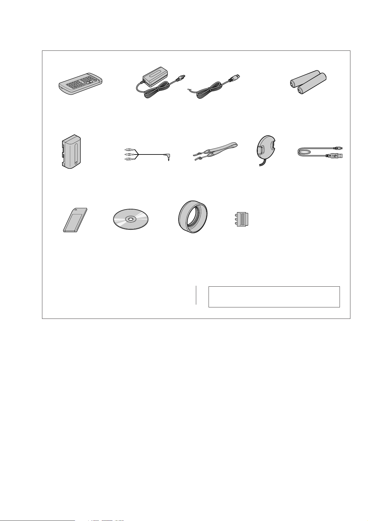
Checking supplied accessories.
Make sure that the following accessories are supplied with your camcorder.
Wireless Remote Commander (1)
RMT-811
1-475-950-21
NP-FM50 battery pack (1)
(not supplied)
Memory Stick (1)
(MSA-4A)
A-7033-740-A
CD-ROM
(SPVD-004 USB Driver)(1)
3-066-676-01
AC-L10A
AC power adaptor (1)
0
1-475-599-11
A/V connecting cable (1.5m) (1)
1-765-080-11
Other accessories
3-067-862-11 MANUAL, INSTRUCTION (ENGLISH/RUSSIAN)
3-067-862-21 MANUAL, INSTRUCTION (FRENCH/GERMAN)(AEP)
3-067-862-31 MANUAL, INSTRUCTION (ENGLISH/DUTCH)(AEP)
Power cord (Main lead)(1) (AEP model)
0
1-769-608-11
Power cord (Main lead)(1) (UK model)
0
1-783-374-11
Shoulder strap (1)
3-987-015-01
Lens hood (1)
3-063-515-01
21-pin adaptor (1)
1-573-291-11
Note : The components identified by mark 0 or dotted
line with mark 0 are critical for safety.
Replace only with part number specified.
Lens cap (1)
X-3949-944-01
Size AA (R6) battery for
Remote Commander (2)
(not supplied)
USB cable (1)
1-757-293-11
— 3 —
Page 4

TABLE OF CONTENTS
SERVICE NOTE
1. POWER SUPPLY DURING REPAIRS ····························· 5
2. TO TAKE OUT A CASSETTE WHEN NOT EJECT
(FORCE EJECT) ································································5
3. DISCHARGING OF THE FLASHLIGHT POWER
SUPPLY CAPACITOR ······················································ 6
3-1. PREPARING THE SHORT JIG········································· 6
3-2. DISCHARGING THE CAPACITOR································· 6
SELF-DIAGNOSIS FUNCTION
1. SELF-DIAGNOSIS FUNCTION······································· 7
2. SELF-DIAGNOSIS DISPLAY ·········································· 7
3. SERVICE MODE DISPLAY ············································· 7
3-1. Display Method ··································································7
3-2. Switching of Backup No. ··················································· 7
3-3. End of Display···································································· 7
4. SELF-DIAGNOSIS CODE TABLE··································· 8
1. MAIN PARTS
1. ORNAMENTAL PARTS···················································· 9
2. DISASSEMBLY······························································· 10
2-1. LCD SECTION (PD-145 BOARD) ·································11
2-2. EVF SECTION (LB-072 BOARD)··································12
2-3. FRONT PANEL SECTION
(MI-043, ML-023, SE-121 BOARDS)····························· 13
2-4. CABINET (R) SECTION (CK-102 BOARD)················· 14
2-5. BT PANEL SECTION, EVF SECTION ·························· 14
2-6. VC-264P BOARD, MECHANISM DECK······················15
2-7. LENS SECTION (JK-207 BOARD)································ 15
2-8. CONTROL SWITCH BLOCK (FK-1800),
CONTROL SWITCH BLOCK (PS-1800)······················· 16
2-9. FLASH UNIT··································································· 17
2-10. PO-006 BOARD, HINGE ASSEMBLY··························· 17
2-11. GRIP BELT ······································································ 18
3. REPAIR PARTS LIST ······················································19
3-1. EXPLODED VIEWS ······················································· 19
3-1-1.OVERALL SECTION ······················································ 19
3-1-2.CABINET (R) SECTION ················································ 20
3-1-3.LCD SECTION ································································21
3-1-4.CABINET (L) SECTION-1 ············································· 22
3-1-5.CABINET (L) SECTION-2 ············································· 23
3-1-6.LENS, EVF SECTION·····················································24
2. GENERAL
Main Features ············································································· 25
Quick Start Guide ······································································ 25
Getting started
Using this manual ··································································· 26
Checking supplied accessories ··············································· 26
Step 1 Preparing the power supply ········································· 26
Installing the battery pack···················································· 26
Charging the battery pack ···················································· 27
Connecting to a wall socket ·················································27
Step 2 Setting the date and time ············································· 28
Step 3 Inserting a cassette······················································· 28
Recording – Basics
Recording a picture································································· 29
Shooting backlit subjects – BACK LIGHT ························· 30
Shooting in the dark – NightShot/Super NightShot ············ 31
Self-timer recording····························································· 31
Checking the recording – END SEARCH/EDITSEARCH/
Rec Review ·········································································· 31
Playback – Basics
Playing back a tape ································································· 32
Viewing the recording on TV ················································· 33
Advanced Recording Operations
Recording a still image on a tape – Tape Photo recording ····· 34
Adjusting the white balance manually···································· 36
Using the wide mode ······························································ 36
Using the fader function ························································· 37
Using special effects – Picture effect······································ 37
Using special effects – Digital effect······································ 38
Using the PROGRAM AE function ········································38
Adjusting the exposure manually ··········································· 39
Focusing manually·································································· 39
Interval recording···································································· 40
Frame by frame recording – Cut recording ···························· 41
Advanced Playback Operation
Playing back a tape with picture effects ································· 41
Playing back a tape with digital effects ·································· 41
Enlarging images recorded on tapes – Tape PB ZOOM ········· 42
Quickly locating a scene using the zero set memory function
Searching the boundaries of recorded tape by title
– Title search········································································ 43
Searching a recording by date – Date search·························· 43
Searching for a photo – Photo search/Photo scan··················· 44
Editing
Dubbing a tape ········································································ 44
Dubbing only desired scenes – Digital program editing ········ 45
Using with analog video unit and personal computer
– Signal convert function····················································· 49
Recording video or TV programmes ······································ 49
Inserting a scene from a VCR – Insert editing························50
Audio dubbing ········································································ 51
Superimposing a title ······························································52
Making your own titles ··························································· 53
Labelling a cassette································································· 54
Customising Y our Camcorder
Changing the menu settings···················································· 54
“Memory Stick” operations
Using a “Memory Stick”– introduction ·································· 56
Recording still images on “Memory Stick”s
– Memory Photo recording ·················································· 59
Recording an image from a tape as a still image ····················61
Recording moving pictures on “Memory Stick”s
– MPEG movie recording ···················································· 61
Recording a picture from a tape as a moving picture ············· 62
Superimposing a still picture in a “Memory Stick”
on a moving picture – MEMORY MIX ·······························63
Copying still images from a tape – Photo save·······················64
Viewing a still picture – Memory photo playback ·················· 64
Viewing a moving picture – MPEG movie playback ············· 65
Viewing images using your computer ···································· 66
Copying the image recorded on “Memory Stick”s to tapes
Enlarging still images recorded on “Memory Stick”s
– Memory PB ZOOM ·························································· 68
Playing back images in a continuous loop – SLIDE SHOW
Preventing accidental erasure – Image protection ··················69
Deleting images ······································································ 69
Writing a print mark – PRINT MARK··································· 70
Using the printer (optional) ···················································· 71
Troubleshooting
Types of trouble and their solutions ········································ 71
Self-diagnosis display ····························································· 73
Warning indicators and messages ··········································· 73
Additional Information
Usable cassettes ······································································ 73
About the “InfoLITHIUM” battery pack································ 74
About i.LINK·········································································· 75
Using your camcorder abroad················································· 75
Maintenance information and precautions······························ 75
Quick Reference
Identifying the parts and controls ··········································· 77
······· 67
······· 68
····· 42
— 4 —
Page 5
SERVICE NOTE
1. POWER SUPPLY DURING REPAIRS
In this unit, about 10 seconds after power is supplied to the battery terminal using the regulated power supply (8.4V), the po wer is shut of f so
that the unit cannot operate.
This following two methods are available to prevent this. Take note of which to use during repairs.
Method 1.
Use the AC power adaptor (AC-L10, AC-VQ800 etc.).
Method 2.
Connect the servicing remote commander RM-95 (J-6082-053-B) to the LANC jack, and set the commander switch to the “ADJ” side.
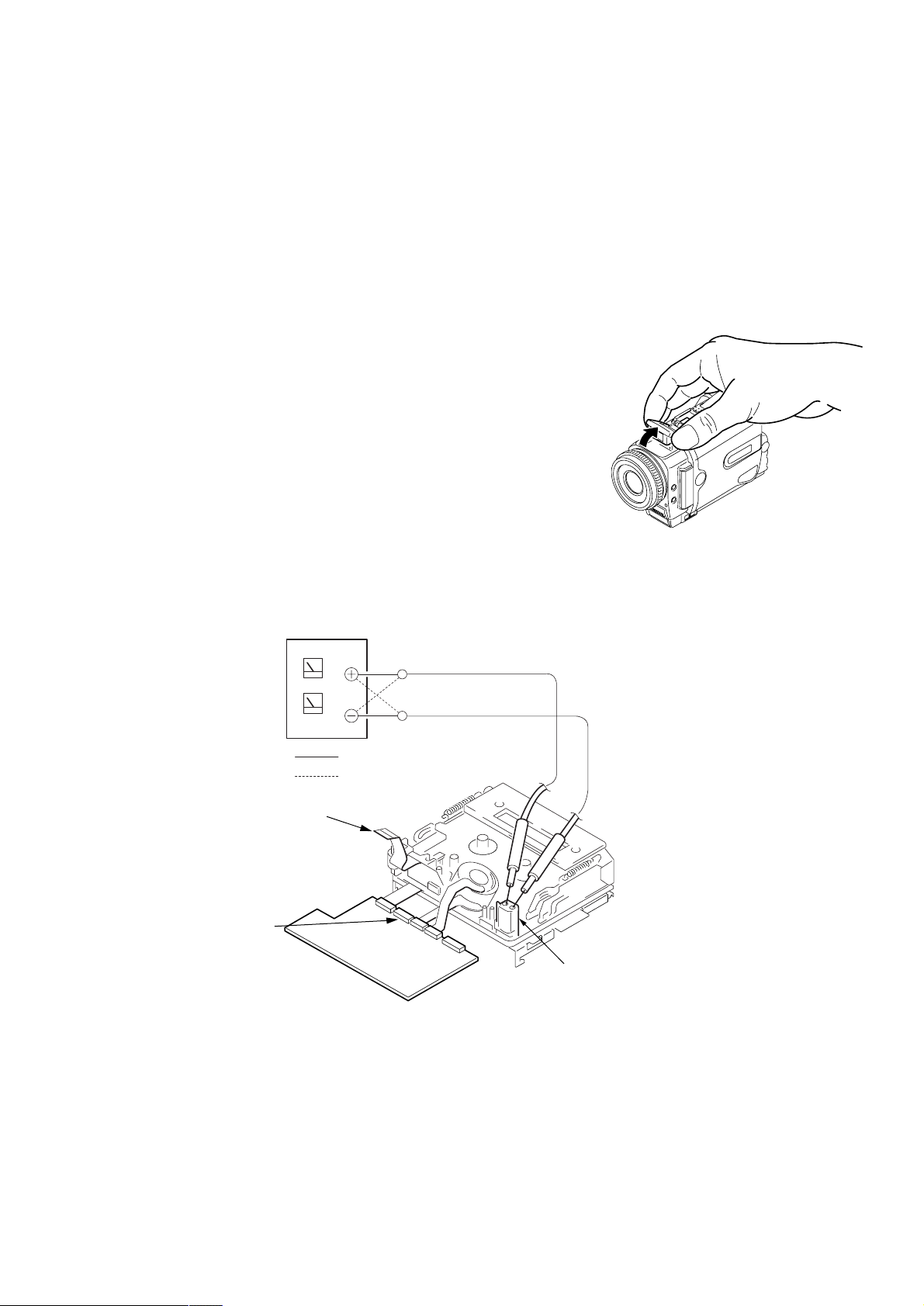
2. TO TAKE OUT A CASSETTE WHEN NOT EJECT
(FORCE EJECT)
1 Open the flash.
(If the flash cannot be opened i the position as shown, remove the top cabinet ref fering
to section 2-4 and open the flash.)
2 Refer to 2-3 to remove the front panel assembly.
3 Refer to 2-4 to remove the upper cabinet assembly.
4 Refer to 2-4 to remove the cabinet (R) assembly.
5 Refer to 2-5 to remove the battery panel section.
6 Refer to 2-5 to remove the VC heat sink and EVF section.
7 Open the VC-264P board.
8 Refer to 2-6 to remove the three screws with which the MD frame assembly is fixed.
9 Remove the mechanism deck and VC-264P board.
0 Disconnect CN006 (27P, 0.3mm) of VC-264P board.
qa Supply +4.5V from the DC power supply to the loading motor and unload with a pressing the cassette compartment.
DC power supply
(+4.5Vdc)
Disconnect from CN006 (27P)
of VC-264P board
CN006
: Unloading
: Loading
VC-264P board
Loading motor
— 5 —
Page 6
3. DISCHARGING OF THE FLASHLIGHT POWER SUPPLY CAPACITOR
The power supply capacitor of the flash unit is charged up to the maximum 300V potential.
There is a danger of electric shock by this high voltage when the capacitor is handled by hand. The electric shock is caused by the charged
voltage which is kept without discharging when the main power of the unit is simply turned off. Therefore, the remaining voltage must be
discharged as described below.
3-1. PREPARING THE SHORT JIG
To preparing the short jig. a small clip is attached to each end of a resistor of 1kΩ/1W (1-215-869-11).
Wrap insulating tape fully around the reads of the resistor to prevent electric shock.
1 kΩ/1 W
Wrap insulating tape.
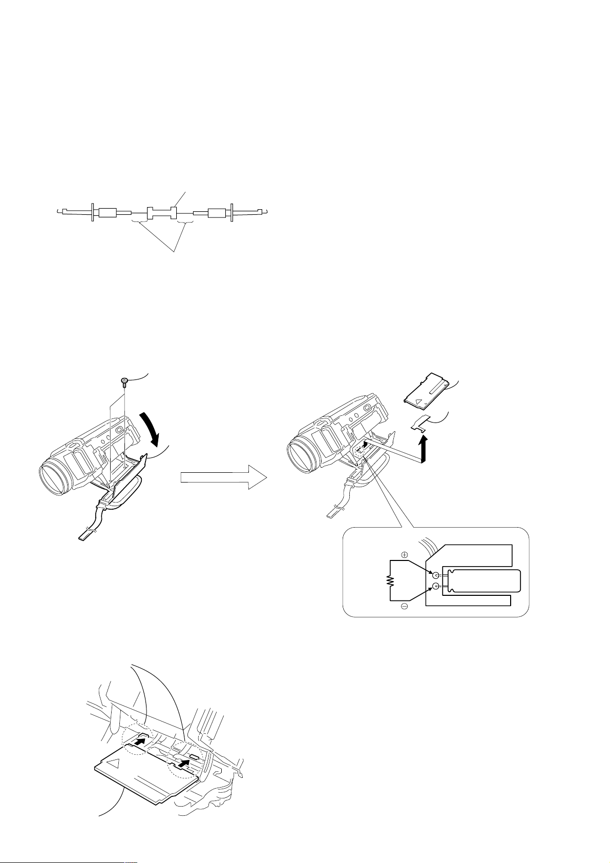
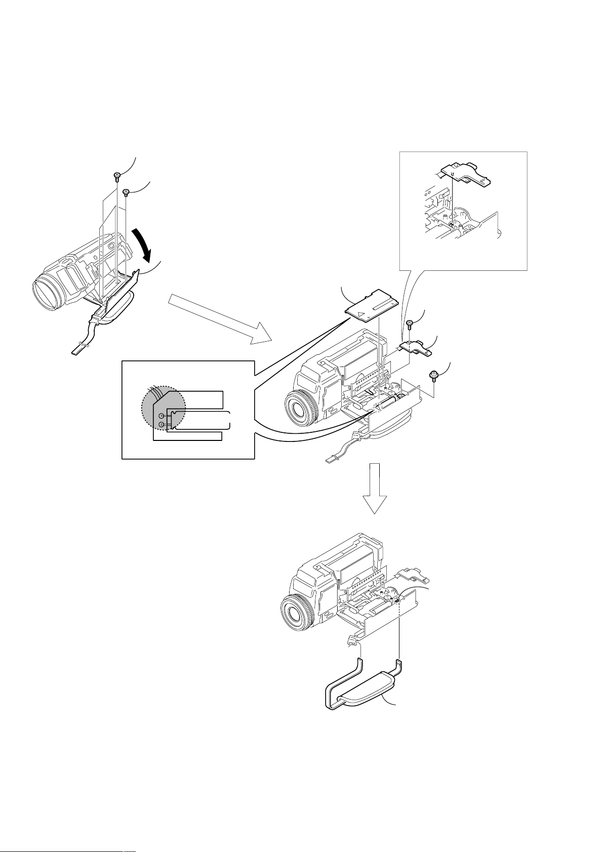
3-2. DISCHARGING THE CAP ACIT OR
1 Remove the power supply (Battery or AC power adaptor).
2 Open the cassette lid (grip cabinet).
3 Remove the two screws with which the grip cover is fixed.
4 Remove the grip cover.
5 Remove the insulation sheet.
6 Short circuit between 3 and # terminal of the capacitor with the short jig about 10 seconds.
3 Two screws, tapping
(M1.7 × 5)
2 Open the cassette lid.
Note for installing the grip cover
When installing the grip cover, insert it in the claws of the grip cabinet.
Two claws
6
Short jig
4 Grip cover
5 Insulation sheet
Flash unit
Power supply
capacitor
Grip cover
— 6 —
Page 7
SELF-DIAGNOSIS FUNCTION
1. SELF-DIAGNOSIS FUNCTION
When problems occur while the unit is operating, the self-diagnosis
function starts working, and displays on the viewf inder, LCD screen
or LCD window what to do. This function consists of two display;
self-diagnosis display and service mode display.
Details of the self-diagnosis functions are provided in the Instruction
manual.
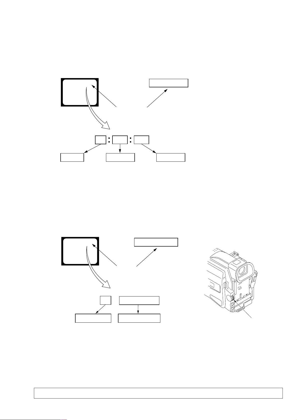
Viewfinder or LCD screen LCD window
C : 3 1 : 1 1
Blinks at 3.2Hz
1 1
Repaired by:
C : Corrected by customer
H : Corrected by dealer
E : Corrected by service
engineer
C
Indicates the appropriate
step to be taken.
E.g.
31 ....Reload the tape.
32 ....Turn on power again.
3 1
Block
2. SELF-DIAGNOSIS DISPLAY
When problems occur while the unit is operating, the counter of the
viewfinder, LCD screen or LCD window consists of an alphabet
and 4-digit numbers, which blinks at 3.2 Hz. This 5-character display
indicates the “repaired by:”, “block” in which the problem occurred,
and “detailed code” of the problem.
C : 3 1 : 11
Detailed Code
Refer to page 8.
Self-diagnosis Code Table.
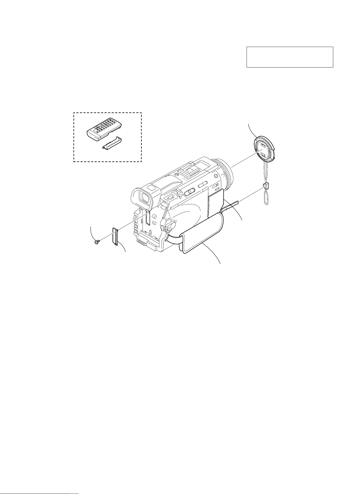
3. SERVICE MODE DISPLAY
The service mode display shows up to six self-diagnosis codes shown in the past.
3-1. Display Method
While pressing the “STOP” key, set the switch from OFF to “VCR”, and continue pressing the “STOP” key for 5 seconds continuously. The
service mode will be displayed, and the counter will show the backup No. and the 5-character self-diagnosis codes.
Viewfinder or LCD screen
[3] C : 3 1 : 1 1
Lights up
[3]
Backup No.
Order of previous errors
C : 3 1 : 1 1
Self-diagnosis Codes
3-2. Switching of Backup No.
By rotating the control dial, past self-diagnosis codes will be shown in order. The backup No. in the [] indicates the order in which the
problem occurred. (If the number of problems which occurred is less than 6, only the number of problems which occurred will be shown.)
[1] : Occurred first time [4] : Occurred fourth time
[2] : Occurred second time [5] : Occurred fifth time
[3] : Occurred third time [6] : Occurred the last time
LCD window
3 C : 3 1 : 11
Control dial
3-3. End of Display
Turning OFF the power supply will end the service mode display.
Note: The “self-diagnosis display” data will be backed up by the coin-type lithium battery of CK-102 board BT3201. When the cabinet (R)(CK-102
board) is removed, the “self-diagnosis display” data will be lost by initialization.
— 7 —
Page 8

4. SELF-DIAGNOSIS CODE TABLE
Self-diagnosis Code
Function
Repaired by:
C
C
C
C
C
C
C
C
C
C
C
C
C
C
C
C
C
C
C
C
C
C
C
E
E
E
E
Block
04
21
22
31
31
31
31
31
31
31
31
31
31
31
31
32
32
32
32
32
32
32
32
61
61
62
62
Detailed
Code
00
00
00
10
11
20
21
22
23
24
30
40
42
10
11
20
21
22
23
24
30
40
42
00
10
00
01
Symptom/State
Non-standard battery is used.
Condensation.
Video head is dirty.
LOAD direction. Loading does not
complete within specified time
UNLOAD direction. Loading does not
complete within specified time
T reel side tape slacking when unloading
Winding S reel fault when counting the
rest of tape.
T reel fault.
S reel fault.
T reel fault.
FG fault when starting capstan.
FG fault when starting drum.
FG fault during normal drum operations.
LOAD direction loading motor time-
out.
UNLOAD direction loading motor
time-out.
T reel side tape slacking when
unloading.
Winding S reel fault when counting the
rest of tape.
T reel fault.
S reel fault.
T reel fault.
FG fault when starting capstan.
FG fault when starting drum
FG fault during normal drum
operations
Difficult to adjust focus
(Cannot initialize focus.)
Zoom operations fault
(Cannot initialize zoom lens.)
Steadyshot function does not work well.
(With pitch angular velocity sensor output
stopped.)
Steadyshot function does not work well.
(With yaw angular v elocity sensor output
stopped.)
Correction
Use the info LITHIUM battery.
Remove the cassette, and insert it again after one hour.
Clean with the optional cleaning cassette.
Load the tape again, and perform operations from the beginning.
Load the tape again, and perform operations from the beginning.
.
Load the tape again, and perform operations from the beginning.
Load the tape again, and perform operations from the beginning.
Load the tape again, and perform operations from the beginning.
Load the tape again, and perform operations from the beginning.
Load the tape again, and perform operations from the beginning.
Load the tape again, and perform operations from the beginning.
Load the tape again, and perform operations from the beginning.
Load the tape again, and perform operations from the beginning.
Remove the battery or power cable, connect, and perform
operations from the beginning.
Remove the battery or power cable, connect, and perform
operations from the beginning.
Remove the battery or power cable, connect, and perform
operations from the beginning.
Remove the battery or power cable, connect, and perform
operations from the beginning.
Remove the battery or power cable, connect, and perform
operations from the beginning.
Remove the battery or power cable, connect, and perform
operations from the beginning.
Remove the battery or power cable, connect, and perform
operations from the beginning.
Remove the battery or power cable, connect, and perform
operations from the beginning.
Remove the battery or power cable, connect, and perform
operations from the beginning.
Remove the battery or power cable, connect, and perform
operations from the beginning.
Inspect the lens block focus MR sensor (Pin 8,9 of CN151 of
CD-320 board) when focusing is performed when the focus ring
is rotated in the focus manual mode, and the focus motor drive
circuit (IC201 of VC-264 board) when the focusing is not
performed.
Inspect the lens block zoom MR sensor (Pin ql,w; of CN151 of
CD-320 board) when zooming is performed when the zoom lens
is operated and the zoom motor drive circuit (IC201 of VC-264
board) when zooming is not performed.
Inspect pitch angular velocity sensor (SE3051 of JK-207 board)
peripheral circuits.
Inspect yaw angular velocity sensor (SE3052 of JK-207 board)
peripheral circuits.
— 8 —
Page 9
1. MAIN PARTS
Note:
• Follow the disassembly procedure in the numerical order given.
• Items marked “*” are not stocked since they are seldom required for routine service.
Some delay should be anticipated when ordering these items.
• The parts numbers of such as a cabinet are also appeared in this section.
Refer to the parts number mentioned below the name of parts to order.
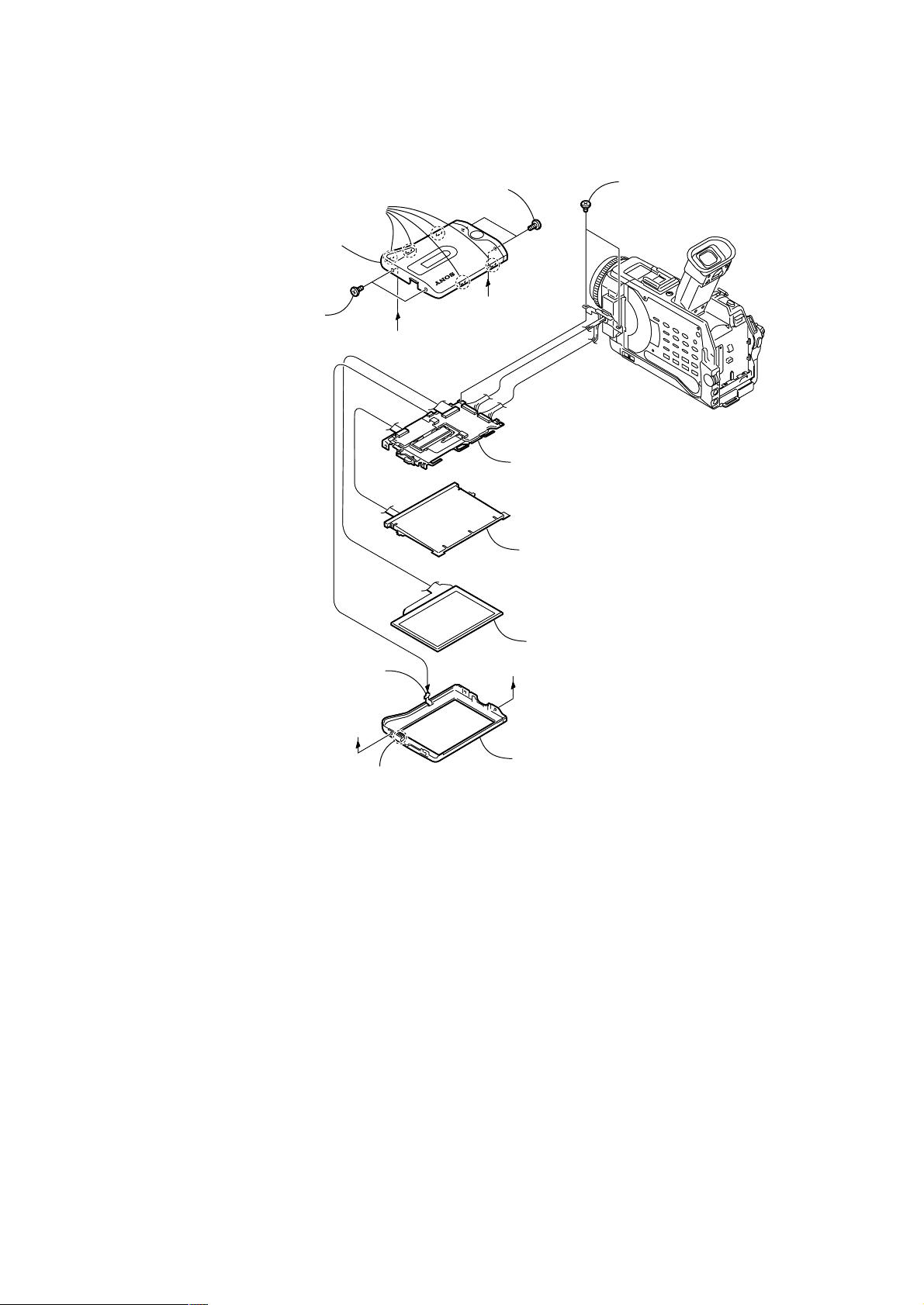
1. ORNAMENTAL PARTS
Remote commander (RMT-811)
1-475-950-21
Battery case lid (for RMT-811)
3-053-056-01
DCR-TRV30E
The components identified by mark 0 or
dotted line with mark 0 are critical for safety.
Replace only with part number specified.
Lens cap assembly
X-3949-944-1
Screw (M1.7 × 4),
lock ace, p2
3-989-735-81
Jack cover assembly
X-3951-455-1
Note: Disassembling the main unit
is necessary to replace it.
CPC lid
3-067-025-01
Grip belt
Note: Disassembling the main unit
is necessary to replace it.
— 9 —
Page 10

2. DISASSEMBLY
The following flow chart shows the disassembly procedure.
2-1. LCD section (PD-145 board)
2-2. EVF section (LB-072 board)
2-3. Front panel section (MI-043, ML-023, SE-121 boards)
DCR-TRV30E
2-4. Cabinet (R) section (CK-102 board)
2-5. BT panel section, EVF section
2-6. VC-264P board, Mechanism deck
2-7. Lens section (JK-207 board)
2-8. Control switch block (FK-1800),
Control switch block (PS-1800)
2-9. Flash unit
2-11. Grip belt
2-10. PO-006 board, Hinge assembly
— 10 —
Page 11
NOTE: F ollo w the disassembly procedure in the numerical order given.
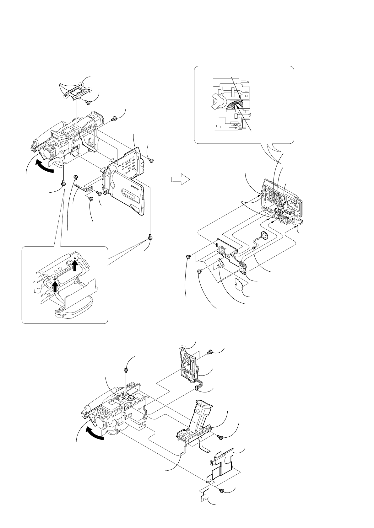
2-1. LCD SECTION (PD-145 BOARD)
3 Five claws
4 P cabinet (C) assembly
1 Two screws
(M1.7 × 4),
lock ace, p2
2 Two screws
(M1.7 × 4),
lock ace, p2
A
A
PD-
PD-
B
B
145
145
qa PD-145 board,
Inverter transformer unit,
Indication LCD block assembly,
P frame assembly
0 Back light
6 Two screws
(M1.7 × 2.5), p
5 Control switch block
(VB-1800) (8P)
A
A
7 Claw
9 Liquid crystal
indicator module
B
B
8 P cabinet (M),
Control switch block (VB-1800)
— 11 —
Page 12

2-2. EVF SECTION (LB-072 BOARD)
1 Raise the EVF in the A direction and
slide it in the B direction.
A
2 VF cabinet (upper)
assembly
B
3 Two tapping screws
(M1.7 × 5)
2 Two tapping screws
(M1.7 × 5)
1Two claws
4 VF electrostatic
sheet
6
3 VF cabinet (lower)
assembly
5 FP-328 flexible board (20P)
— 12 —
Page 13
2-3. FRONT PANEL SECTION (MI-043, ML-023, SE-121 BOARDS)
2 Two screws
(M1.7 × 4),
lock ace, p2
1 Open the flash unit
4 Screw
(M1.7 × 4),
lock ace, p2
3 Open the jack
cover assembly
7 Front panel section
5 Screw
(M1.7 × 4),
lock ace, p2
6 FP-327 flexible board (37P)
4 Two tapping
screws
(M1.7 × 3.5)
6 Jack cover
assembly
8 SE-121 board
(8P)
2 Claw
5 Microphone
retainer
q; ML-023 board
9 Tapping screw
(M1.7 × 3.5)
1 Screw
(M1.7 × 2.5), p
7 ML-043 board
3 Microphone
unit (4P)
4 Tapping screw
(M1.7 × 3.5)
5 Photo clamp
1 Tapping screw
(M1.7 × 3.5)
2 FB PWB
retainer
3 Tapping screw
(M1.7 × 3.5)
6 Muffle sheet
7 SE-121 board
— 13 —
Page 14
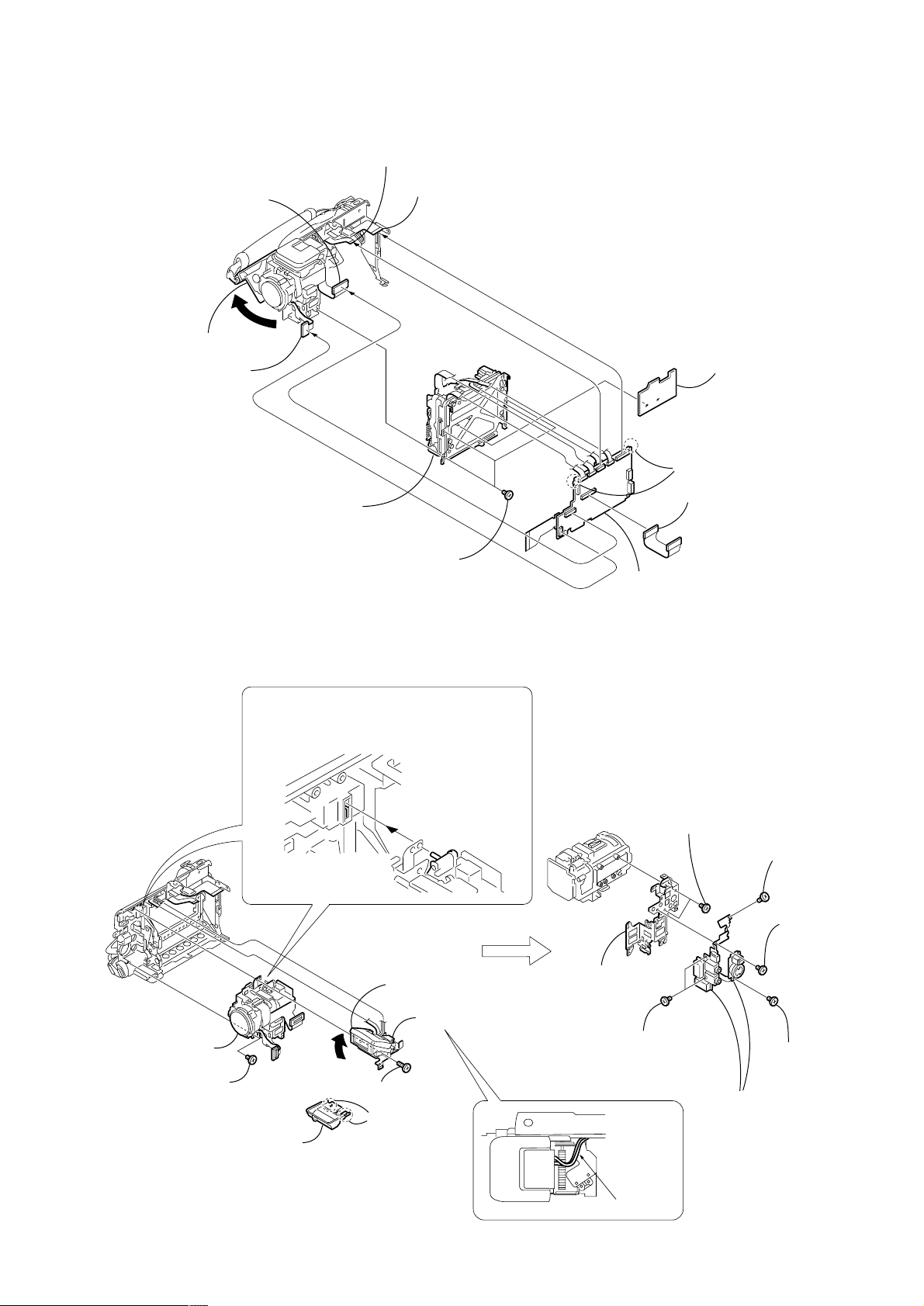
2-4. CABINET (R) SECTION (CK-102 BOARD)
k
2 Three claws
3 TOP cabinet assembly
1 Screw
(M1.7 × 4),
lock ace, p2
5 Screw
(M1.7 × 4),
lock ace, p2
PRECAUTION DURING INSTALLATION
(ROUTING OF HARNESS)
If must not go outside the upper and
lower ribs.
7 Open the
cassette lid
8 Screw
(M1.7 × 4),
lock ace, p2
qs Joint
qa Screw
0 Screw
(M1.7 × 2.5), p
(M1.7 × 2.5), p
9 Screw
(M1.7 × 4),
lock ace, p2
qd Cabinet (R) section
4 Screw
(M1.7 × 2.5), p
6 Screw
(M1.7 × 4),
lock ace, p2
8 Five tapping
screws
(M1.7 × 3.5)
Extra length inside the cabinet is
as much as shown.
1 Control switch block
(KP-1800) (7P)
9 Two claws
CK-102
CK-102 board
qs
4
SP insulating sheet
6 Speaker retainer
5 Two tapping
screws
(M1.7 × 3.5)
q; Harness
(PC-118) (12P)
qa Harness
(PC-119) (14P)
3 FP-181 flexible
board (6P)
2 PO-006
board (6P)
7 Speaker (2P)
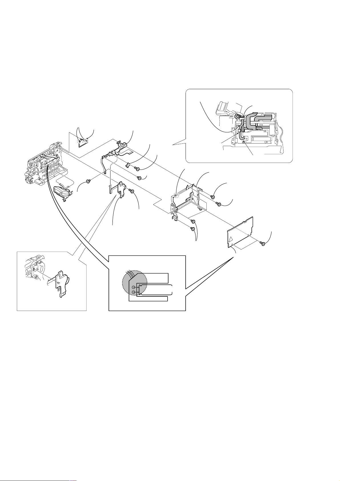
2-5. BT PANEL SECTION, EVF SECTION
9 Screw
(M1.7 × 2.5), p
q; Control switch block
(FK-1800) (15P)
VC-264P
3 Open the
cassette lid
qa FP-331 flexible board (9P)
4 Claw
5 BT panel section
1 Battery terminal
board (6P)
6 KAB sheet
2 Two screws
(M1.7 × 4),
lock ace, p2
qd EVF section
qs Two tapping
screws
(M1.7 × 5)
8 VC heat sin
7 Two screws
(M1.7 × 2.5), p
— 14 —
Page 15
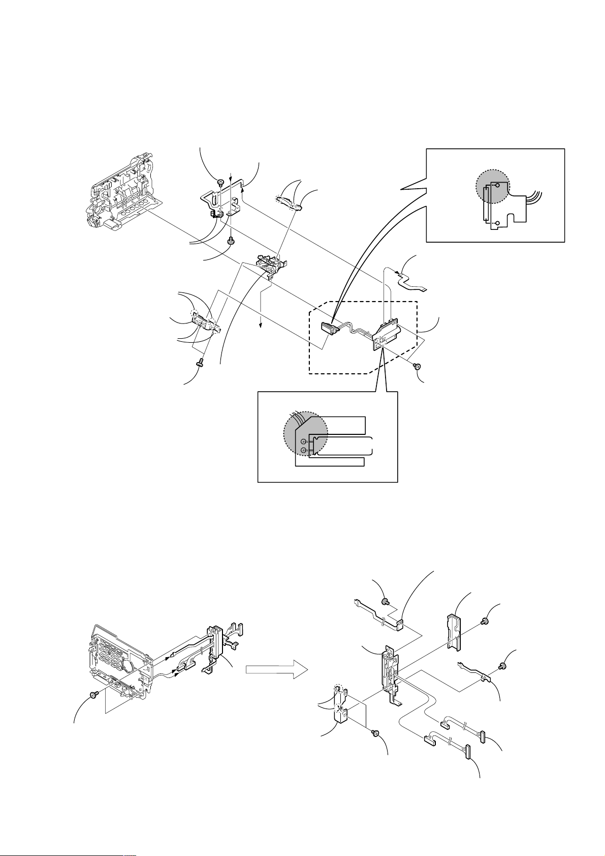
2-6. VC-264P BOARD, MECHANISM DECK
3 FP-330 flexible board (23P)
CD-320P board
4
(50P)
q; Open the
cassette lid
5
JK-207 board
(40P)
qa Mechanism deck,
MD frame assembly,
Cassette compartment cover
9 Three screws
(M1.7 × 2.5), p
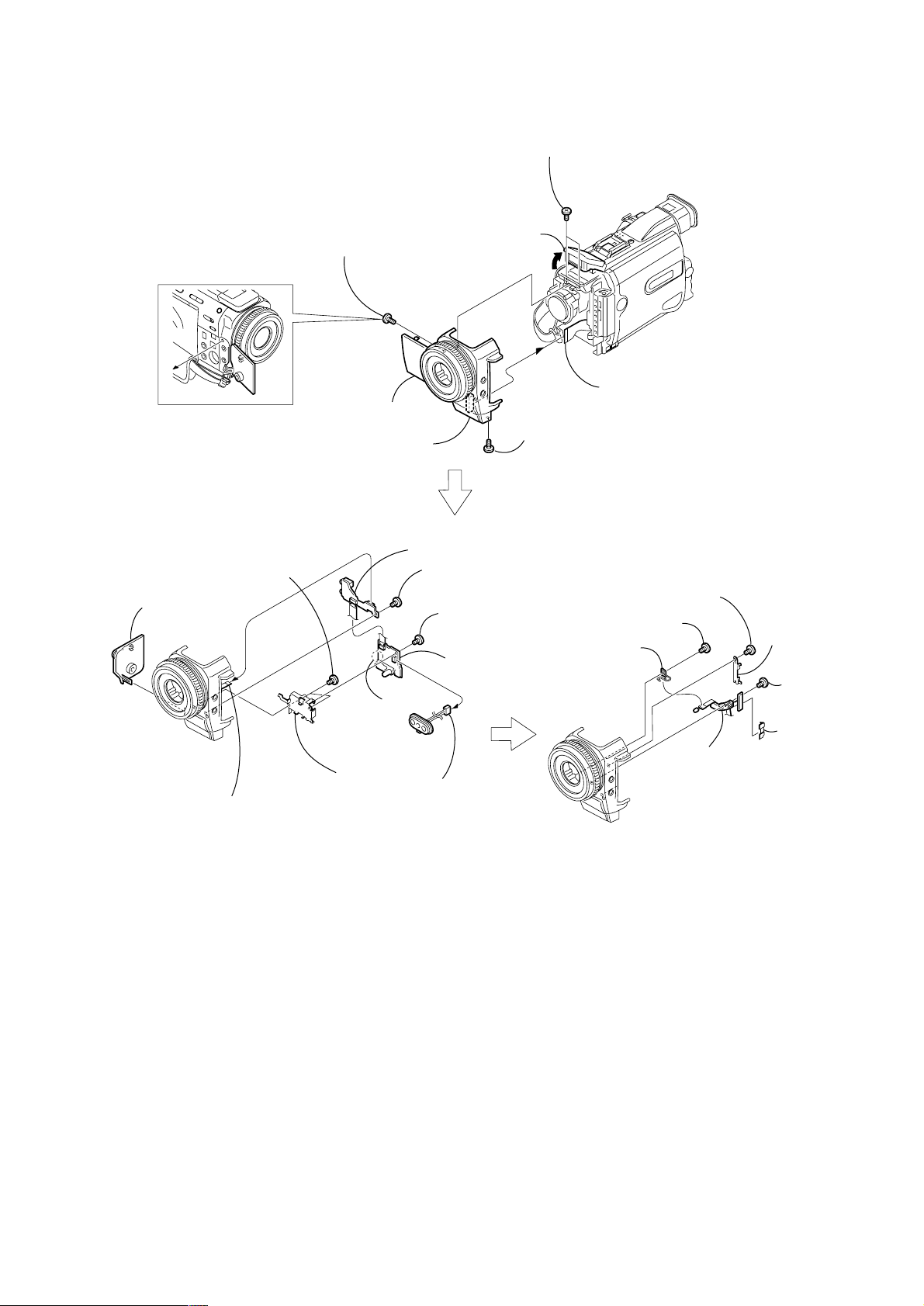
2-7. LENS SECTION (JK-207 BOARD)
2 Control switch block
(FK-1800) (45P)
VC-264P
6 Two claws
1 FP-325 flexible board
(70P)
7
VC-264P board
8 MD heat
insulating sheet
7 Lens section
6 Tapping screw
(M1.7 × 3.5)
PRECAUTION DURING INSTALLATION
Note on attachment
When attaching the lens block, flip up the switch
actuator and insert it to the up position of the
NIGHT SHOT lever in the direction as shown.
1 Open the flash unit
5 Flash unit
4 Tapping screw
(M1.7 × 5)
2 T wo dowels
3 ST cover
6 Lens frame
5 Two screws
(M1.7 × 2.5), p
PRECAUTION DURING
INSTALLATION
1 Two tapping screws
(M1.7 × 3.5)
2 Screw
(M1.7 × 2.5), p
3 Screw
(M1.7 × 2.5), p
4 Screw
(M1.7 × 2.5), p
7 JK-207 board
Give extra play of abut 90 degrees.
— 15 —
Page 16
2-8. CONTROL SWITCH BLOCK (FK-1800), CONTROL SWITCH BLOCK (PS-1800)
Note: The power supply capacitor of the flash unit is charged to the high tension voltage as high as 300 V at a maximum. You will get
electrical shock when you touch the terminal of the charged capacitor. The charged potential remains even after the main power
of the machine is turned off. Discharge the remaining power in the capacitor referring to Service Note (page 6).
ROUTING OF THE HARNESS AND FLEXIBLE
AROUND THE HARNESS RETAINER.
Two harnesses must be aligned flat along this
surface and must not be overlapped.
Harness retainer
1 Two claws
PRECAUTION DURING
INSTALLATION
2 Zoom cover
5 Screw
(M1.7 × 2.5), p
qf Control switch block
(FK-1800)
7 Harness
retainer
6 Tapping
screw
(M1.7 × 5)
qd Tapping
screw
(M1.7 × 3.5)
qg Tapping
screw
(M1.7 × 3.5)
qh Control switch block
(PS-1800)
Caution: High voltage
Power supply
capacitor
Engage here.
qa Claw
0 Four tapping
screws
(M1.7 × 3.5)
Rote the extra length this side.
qs CS frame assembly
8 Tapping
screw (M1.7 × 3.5)
9 Tapping
screw
(M1.7 × 5)
3 Two tapping
screws
(M1.7 × 5)
4 Grip cover
(Note)
To attach, align the switch
position as shown.
Flash unit
— 16 —
Page 17
2-9. FLASH UNIT
A
A
1 Two tapping
screws
(M1.7 × 3.5)
2 FP-330 flexible board (23P)
qa Two claws
0 Two dowels
qs ST cabinet (lower)
9 ST cabinet (upper)
(Note)
qf Flash unit
qd ST hinge assembly
4 Screw
(M1.7 × 2.5), p
3 Plunger solenoid (6P)
6 Plunger solenoid
5 Bolt screw (M1.4)
8 Two claws
7 Two tapping
screws
(M1.7 × 5)
Xenon tube
Note:
The power supply capacitor of the flash unit is charged to the high tension voltage as high as 300 V at a maximum. You will get
electrical shock when you touch the terminal of the charged capacitor. The charged potential remains even after the main power
of the machine is turned off. Discharge the remaining power in the capacitor referring to Service Note (page 6).
Caution: High voltage
Caution: High voltage
Flash unit
Power supply
capacitor
2-10. PO-006 BOARD, HINGE ASSEMBLY
1 Two screws
(M1.7 × 4),
lock ace, p2
Remove the LCD unit referring to section “2-1. DISASSEMBLY” of Level 2 before starting the following disassembling
work.
2
4 Two claws
5 Hinge cover (front)
q; Screw
(M1.7 × 2.5), p
qs Hinge assembly
qa FP-181 flexible board
3 Two screws
(M1.7 × 2.5),
lock ace, p2
7 Hinge cover (rear)
6 Screw
(M1.7 × 2.5),
lock ace, p2
1 Screw
(M1.7 × 2.5), p
2 PO-006 board
8 Harness
(PC-118) (12P)
9 Harness
(PC-119) (14P)
— 17 —
Page 18
2-11. GRIP BELT
Note:
The power supply capacitor of the flash unit is charged to the high tension voltage as high as 300 V at a maximum. You will get
electrical shock when you touch the terminal of the charged capacitor. The charged potential remains even after the main power
of the machine is turned off. Discharge the remaining power in the capacitor referring to Service Note (page 6).
PRECAUTION DURING
2 Two tapping
screws (M1.7 × 5)
3 Three tapping
screws (M1.7 × 3.5)
INSTALLATION
1 Open the
cassette lid
Caution: High voltage
Power supply
capacitor
Flash unit
To attach, align the switch
position as shown.
4 Grip cover
5 Tapping
screw (M1.7 × 3.5)
6 Control switch block
(PS-1800)
7 Screw
(M2 × 4)
— 18 —
8 Claw
9 Grip belt
Page 19
3. REPAIR PARTS LIST
Cabinet (L) section
(See page 22, 23)
Cabinet (R) section
(See page 20)
1
1
2
4
4
4
4
11
9
9
5
22
18
9
9
9
17
4
7
8
9
3
9
9
20
21
10
12
13
14
15
16
6
not
supplied
not
supplied
MIC901
19
3-1. EXPLODED VIEWS
NOTE:
• -XX, -X mean standardized parts, so they may
have some differences from the original one.
• Items marked “*” are not stocked since they
are seldom required for routine service. Some
delay should be anticipated when ordering these
items.
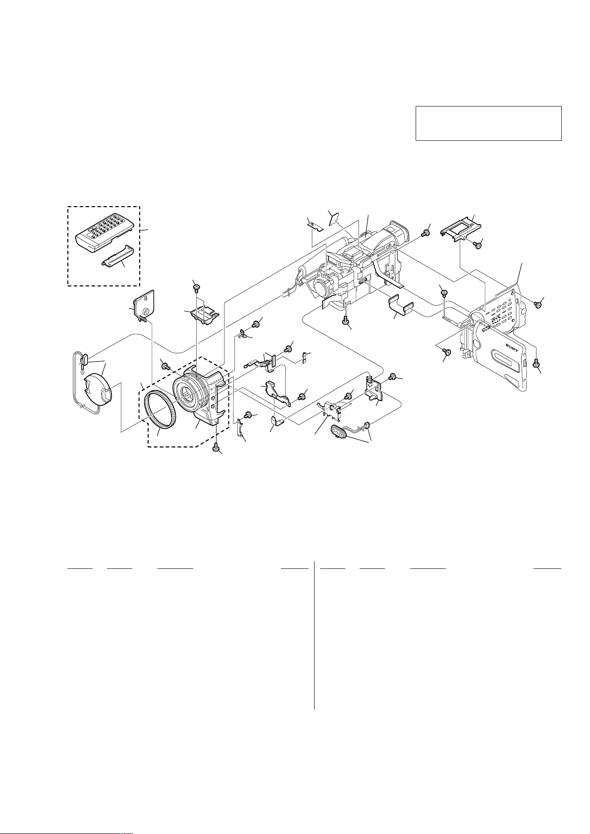
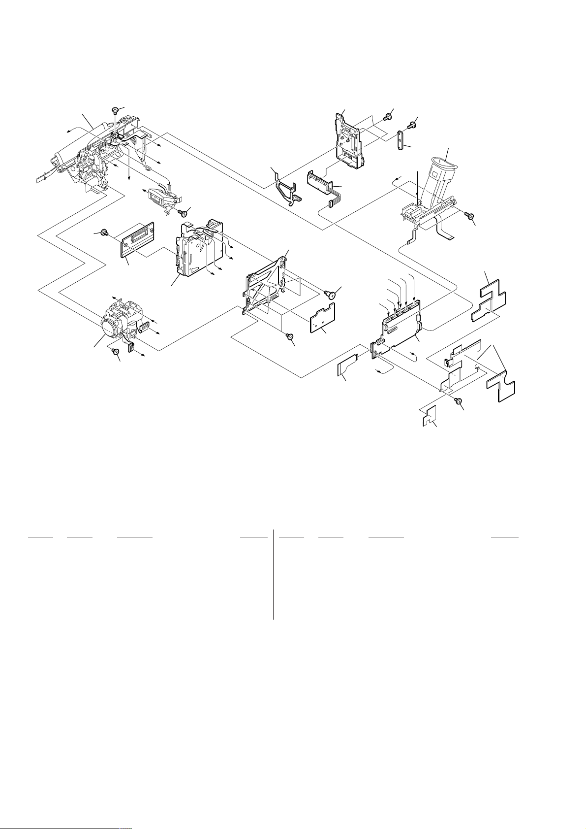
3-1-1. OVERALL SECTION
• The mechanical parts with no reference number
in the exploded views are not supplied.
The components identified by mark 0 or
dotted line with mark 0 are critical for safety.
Replace only with part number specified.
Ref. No. Part No. Description Remarks Ref. No. Part No. Description Remarks
1 4-974-725-01 SCREW (M1.7X2.5), P
2 not supplied MI-043 BOARD, COMPLETE
3 3-066-994-01 MF RUBBER
4 3-713-791-51 SCREW (M1.7X3.5), TAPPING, P2
5 3-067-081-11 SHEET, POWER
6 not supplied ML-023 BOARD, COMPLETE
7 1-681-511-11 FP-329 FLEXIBLE BOARD
8 3-067-006-01 RETAINER, FB PWB
9 3-989-735-81 SCREW (M1.7), LOCK ACE, P2
10 X-3951-556-1 PANEL ASSY, FRONT
11 3-067-007-01 SHEET, MUFFLE
12 X-3949-944-1 CAP ASSY, LENS
13 X-3951-455-1 COVER ASSY, JACK
14 3-066-974-01 ST COVER
15 3-067-008-01 CLAMP, PHOTO
16 not supplied SE-121 BOARD, COMPLETE
17 1-681-508-21 FP-325 FLEXIBLE BOARD
18 X-3951-555-1 CABINET ASSY, TOP
19 3-989-735-01 SCREW (M1.7), LOCK ACE, P2
20 1-475-950-21 REMOTE COMMANDER (RMT-811)
21 3-053-056-01 LID, BATTERY CASE (FOR RMT-811)
22 3-068-834-01 SHEET, TS
MIC901 1-418-351-11 MICROPHONE UNIT
— 19 —
Page 20
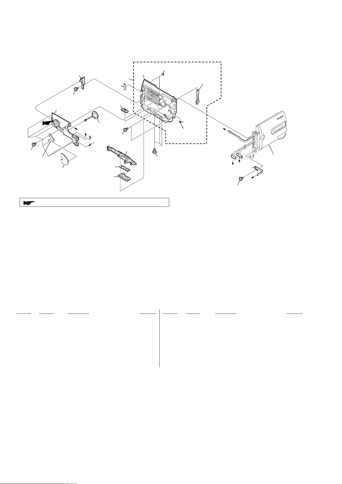
3-1-2. CABINET (R) SECTION
not
59
supplied
61
64
57
60
51
52
53
57
not
supplied
58
CK-102
55
A
B
SP901
C
D
54
: BT3201 (Lithium battery) CK-102 board on the mount position.
51
56
not
supplied
not
supplied
A
B
62
C
63
D
LCD section
(See page 21)
Ref. No. Part No. Description Remarks Ref. No. Part No. Description Remarks
51 3-055-573-01 SCREW (M1.7), LOCK ACE, P2
52 X-3951-440-1 FRAME ASSY, BOTTOM
* 53 3-069-706-01 SHEET, TRIPOD CONDUCTIVE
54 3-055-257-01 TRIPOD (LARGE)
55 3-067-122-01 SHEET, SP INSULATING
56 3-959-978-02 CUSHION, PANEL
57 3-713-791-51 SCREW (M1.7X3.5), TAPPING, P2
58 not supplied CK-102 BOARD, COMPLETE
59 1-476-611-11 SWITCH BLOCK, CONTROL (KP-1800)
60 3-055-324-01 KNOB, EJECT
61 X-3951-557-1 CABINET (R) ASSY
62 4-974-725-01 SCREW (M1.7X2.5), P
63 not supplied PO-006 BOARD, COMPLETE
64 3-060-164-01 TAPE (B)
SP901 1-529-590-11 SPEAKER (2.0CM)
— 20 —
Page 21
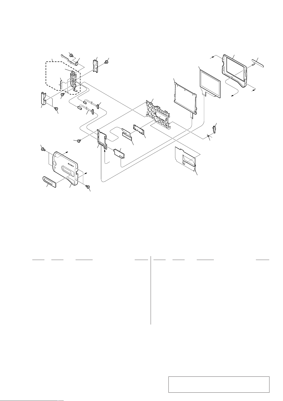
3-1-3. LCD SECTION
109
101
110
not
supplied
113
114
103
103
103
C
111
108
B
112
104
107
PD
145
-
113
A
105
LCD902
106
not
supplied
ND901
LCD901
not
supplied
C
118
117
A
115
116
B
119
102
101
Ref. No. Part No. Description Remarks Ref. No. Part No. Description Remarks
101 3-989-735-81 SCREW (M1.7), LOCK ACE, P2
102 X-3951-447-1 CABINET (C) ASSY, P
103 4-974-725-01 SCREW (M1.7X2.5), P
104 not supplied PD-145 BOARD, COMPLETE
0 105 not supplied TRANSFORMER UNIT, INVERTER
106 3-055-289-01 HOLDER, LCD
107 1-960-425-11 HARNESS (PC-118)(12P)
108 1-960-426-11 HARNESS (PC-119)(14P)
109 3-067-026-01 COVER (FRONT), HINGE
110 X-3951-442-1 HINGE ASSY
111 1-677-563-41 FP-181 FLEXIBLE BOARD
112 3-067-027-01 COVER (REAR), HINGE
113 3-989-735-01 SCREW (M1.7), LOCK ACE, P2
114 3-941-343-21 TAPE (A)
115 3-067-032-01 P CABINET (M)
116 1-476-612-11 SWITCH BLOCK, CONTROL (VB-1800)
117 3-067-078-01 BUTTON, PANEL OPEN
118 3-059-740-01 SPRING (P), TORSION
119 3-067-030-21 PLATE, P ORNAMENTAL
LCD901 not supplied INDICATOR MODULE LIQUID CRYST
LCD902 not supplied INDICATION LCD BLOCK ASSY
0 ND901 not supplied TUBE, FLUORESCENT, COLD CATHODE
— 21 —
Note : The components identified by mark 0 or dotted
line with mark 0 are critical for safety.
Replace only with part number specified.
Page 22
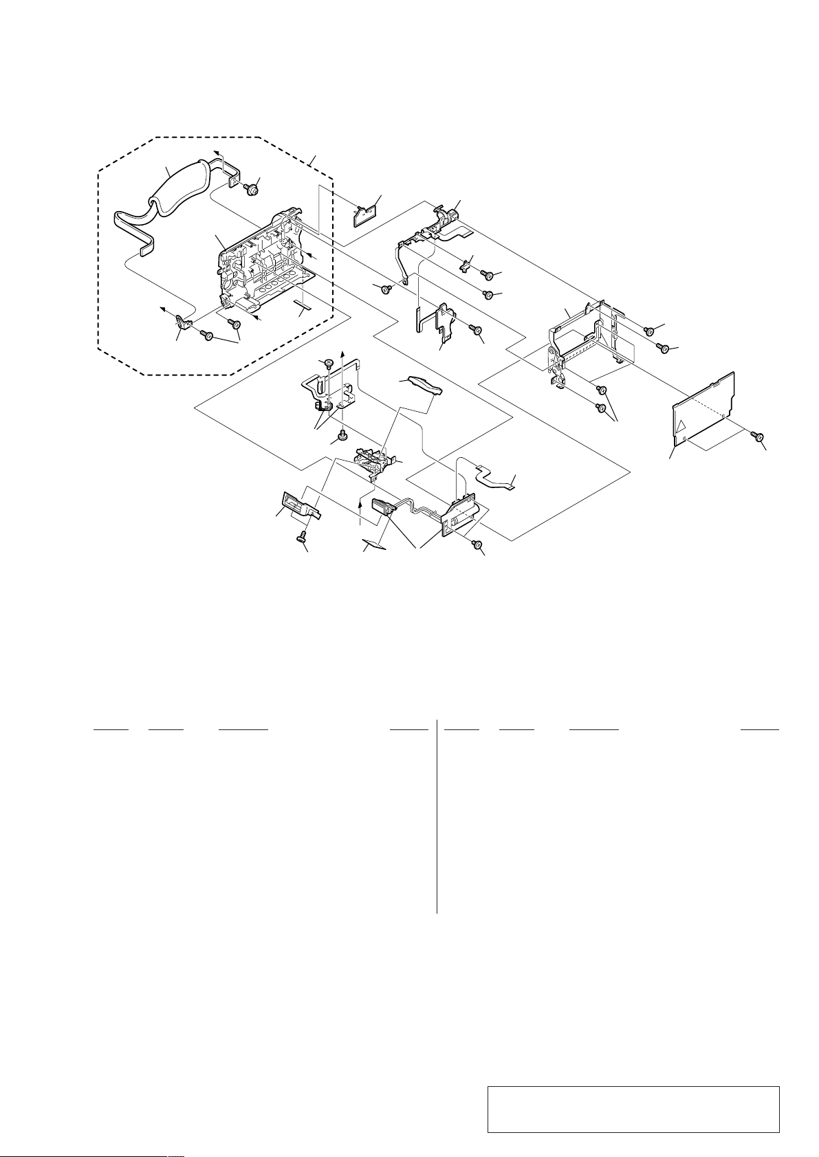
3-1-4. CABINET (L) SECTION-1
Cabinet (L) section-2
(See page 23)
J
160
Lens section
(See page 24)
B
B
159
158
151
I
A
Mechanism deck
A
K
G
L
H
161
C
D
F
E
162
156
151
163
BT901
155
not
supplied
153
C
K
157
F
G
E
D
VC-264P
J
H
L
157
EVF section
(See page 24)
154
I
152
161
not
supplied
not
supplied
151
not
supplied
Ref. No. Part No. Description Remarks Ref. No. Part No. Description Remarks
151 4-974-725-01 SCREW (M1.7X2.5), P
152 not supplied VC-264P BOARD, COMPLETE (SERVICE)
153 1-681-509-11 FP-327 FLEXIBLE BOARD
154 3-067-025-01 CPC LID
155 3-059-718-01 SCREW (M1.4X1.5)
156 X-3951-443-1 FRAME ASSY, MD
157 3-989-735-81 SCREW (M1.7), LOCK ACE, P2
158 3-713-791-51 SCREW (M1.7X3.5), TAPPING, P2
159 3-059-722-03 COVER, CASSETTE COMPARTMENT
160 3-989-735-11 SCREW (M1.7), LOCK ACE, P2
161 3-713-791-11 SCREW (M1.7X5), TAPPING, P2
162 3-067-024-01 BRACKET (LOWER), STRAP
163 X-3951-446-1 PANEL ASSY, BT
BT901 1-694-772-11 TERMINAL BOARD, BATTERY
— 22 —
Page 23
3-1-5. CABINET (L) SECTION-2
213
A
215
B
not
supplied
214
207
A
206
212
209
211
208
216
B
C
208
C
217
210
205
220
218
219
202
207
202
203
221
202
201
202
207
207
207
Ref. No. Part No. Description Remarks Ref. No. Part No. Description Remarks
201 3-067-113-01 COVER, GRIP
202 3-713-791-51 SCREW (M1.7X3.5), TAPPING, P2
203 1-681-512-11 FP-330 FLEXIBLE BOARD
0 204 not supplied FLASH UNIT
205 X-3951-439-1 HINGE ASSY, ST
206 3-066-973-01 ST CABINET (LOWER)
207 3-713-791-11 SCREW (M1.7X5), TAPPING, P2
208 4-974-725-01 SCREW (M1.7X2.5), P
209 1-454-984-11 SOLENOID, PLUNGER
210 3-066-972-01 ST CABINET (UPPER)
211 3-052-245-01 BOLT (M1.4)
222
204
202
* 212 3-055-189-01 FOOT (A)
213 3-061-550-01 BELT, GRIP
214 3-679-362-11 SCREW
215 3-059-825-01 BRACKET (FRONT), GRIP BELT
216 X-3951-554-1 CABINET (L) ASSY
217 3-067-112-01 COVER, ZOOM
218 1-476-613-11 SWITCH BLOCK, CONTROL (FK-1800)
219 3-067-080-01 RETAINER, HARNESS
220 1-476-610-11 SWITCH BLOCK, CONTROL (PS-1800)
221 X-3951-438-1 FRAME ASSY, CS
222 3-067-084-01 BLIND, ST
— 23 —
Note : The components identified by mark 0 or dotted
line with mark 0 are critical for safety.
Replace only with part number specified.
Page 24
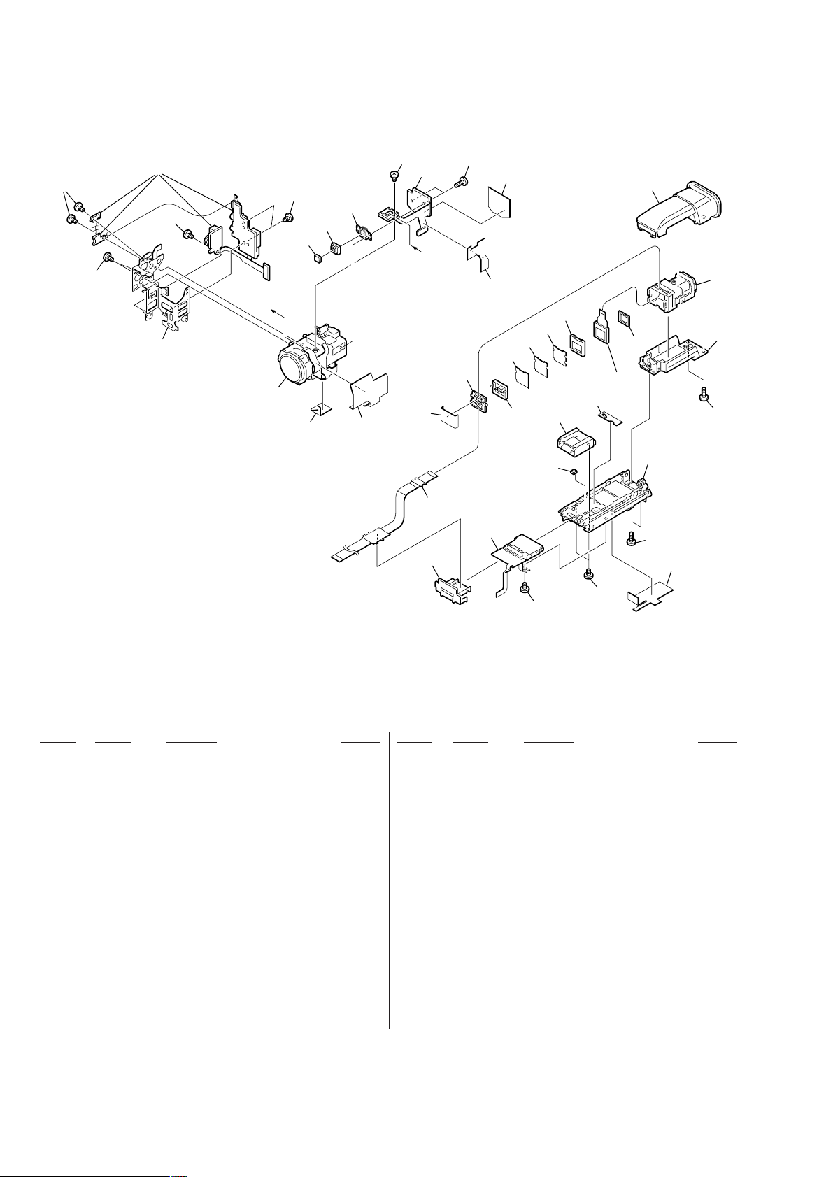
3-1-6. LENS, EVF SECTION
255
253
254
255
252
A
251
255
256
279
257
IC201
260
253
280
258
A
272
276
259
271
282
275
281
269
270
268
267
273
278
266
LCD903
277
265
262
263
264
259
274
259
261
253
255
Ref. No. Part No. Description Remarks Ref. No. Part No. Description Remarks
251 not supplied DEVICE, LENS LSV-690A
252 3-066-988-01 FRAME, LENS
253 3-713-791-51 SCREW (M1.7X3.5), TAPPING, P2
254 not supplied JK-207 BOARD, COMPLETE
255 4-974-725-01 SCREW (M1.7X2.5), P
256 not supplied FILTER BLOCK, OPTICAL (OFB-04-26)
257 not supplied RUBBER (W), SEAL
258 not supplied CD-320P BOARD, COMPLETE
259 3-713-791-11 SCREW (M1.7X5), TAPPING, P2
260 3-067-094-01 LF SHEET
261 3-067-069-01 SHEET, VF FLEXIBLE RETAINER
262 X-3951-451-1 CABINET (UPPER) ASSY, VF
263 X-3951-453-1 LENS ASSY, VF
264 X-3951-452-1 CABINET (LOWER) ASSY, VF
265 3-059-734-01 CUSHION (1), LCD
268 not supplied SHEET (2) (138), PRISM
269 not supplied ILLUMINATOR (1)
270 3-065-058-01 GUIDE, LAMP
271 not supplied LB-072 BOARD, COMPLETE
272 1-681-510-11 FP-328 FLEXIBLE BOARD
273 1-815-124-11 CONNECTOR, EXTERNAL (HOT SHOE)
274 X-3951-441-1 BASE ASSY, VF
275 1-681-513-21 FP-331 FLEXIBLE BOARD
276 3-067-067-01 GUIDE, VF FLEXIBLE
277 3-067-834-01 SHEET, TS
278 3-067-897-01 H SPACER
279 3-067-688-01 L SHEET 2
280 3-069-000-01 SHEET, VF ELECTROSTATIC
281 3-069-819-01 SHEET, CD PROTECTION
282 3-068-830-01 SHEET, KK
266 not supplied CUSHION (138), LCD
267 not supplied SHEET (1) (138), PRISM
IC201 not supplied CCD BLOCK ASSY (CCD IMAGER)
LCD903 not supplied LCX033AN-J
— 24 —
Page 25
English
Main Features
Taking moving or still images, and playing them back
•Recording a picture (p. 26)
•Recording a still image on a tape (p. 48)
•Playing back a tape (p. 39)
•Recording still images on “Memory Stick”s (p. 153)
•Recording moving pictures on “Memory Stick”s (p. 164)
•Viewing a still image recorded on “Memory Stick”s (p. 176)
•Viewing a moving picture on “Memory Stick”s (p. 180)
Capturing images on your computer
•Using with an analog video unit and your computer (p. 107)
•Viewing images recorded on “Memory Stick”s using the USB cable (p. 182)
Other uses
Functions to adjust exposure in the recording mode
•Back light (p. 33)
•NightShot/Super NightShot (p. 34)
•Recording images with the flash (p. 49, 158)
•PROGRAM AE (p. 65)
•Adjusting the exposure manually (p. 68)
Functions to give images more impact
•Digital zoom (p. 31) The default setting is set to OFF. (To zoom greater than 10
zoom power in D ZOOM in the menu settings.)
•Fader (p. 58)
•Picture effect (p. 61)
•Digital effect (p. 62)
•Digital program editing (p. 93)
•Title (p. 121, 125)
•MEMORY MIX (p. 170)
Functions to give a natural appearance to your recordings
•Manual focus (p. 69)
•Sports lesson mode (p. 65)
•Landscape mode (p. 65)
Functions to use after recording
•END SEARCH/EDITSEARCH/Rec review (p. 37)
•DATA CODE (p. 40)
•SUPER LASER LINK (p. 46)
•Tape PB ZOOM (p. 79)/Memory PB ZOOM (p. 190)
•Zero set memory (p. 81, 113)
•Title search (p. 82)
4
•HiFi SOUND (p. 131, 223)
DCR-TRV30E
2. GENERAL
This section is extracted
from instruction manual.
×, select the digital
English
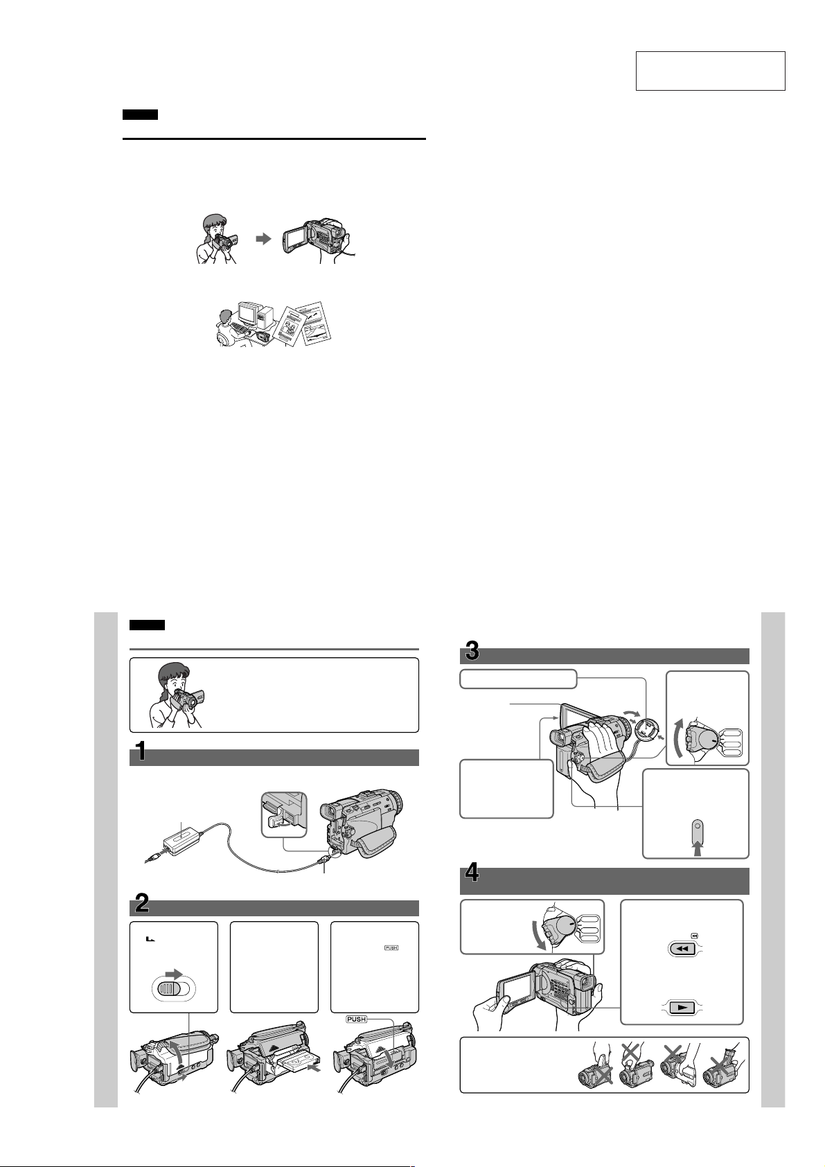
Quick Start Guide
This chapter introduces you to the basic features of your
camcorder. See the page in parentheses “()” for more
information.
Connecting the mains lead (p. 21)
Use the battery pack when using your camcorder outdoors (p. 17).
Open the DC IN
AC power adaptor (supplied)
Quick Start Guide
1Slide OPEN/
EJECT in the
direction of the arrow
and open the lid.
Inserting a cassette (p. 24)
jack cover.
2Push the middle
portion of the back of
the cassette to insert.
Insert the cassette in a
straight line deeply
into the cassette
compartment with the
window facing out.
Connect the plug with its v
mark facing up.
3Close the cassette
compartment by
pressing the
mark on the cassette
compartment.
After the cassette
compartment goes
down completely,
close the lid until it
clicks.
Recording a picture
1
Remove the lens cap.
Viewfinder
When the LCD panel is
closed, use the
viewfinder placing your
eye against its eyecup.
3
Press OPEN to open the
LCD panel.
The picture appears on
the screen.
When you purchase your camcorder, the clock setting
is set to off. If you want to record the date and time for
a picture, set the clock setting before recording (p. 22).
Monitoring the playback picture on the LCD
screen
(p. 39)
1
Set the POWER
switch to VCR
while pressing the
small green button.
(p. 26)
2
VCR
OFF(CHG)
R
E
W
O
P
CAMERA
MEMORY
Press m to rewind the tape.
3
Press N to start playback.
2
Set the POWER
switch to CAMERA
while pressing the
small green button.
POWER
4
Press START/STOP. Your
camcorder starts recording.
To stop recording, press
START/STOP again.
REW
PLAY
VCR
OFF(CHG)
CAMERA
MEMORY
Quick Start Guide
10
— 25 —
NOTE
Do not pick up your camcorder by
holding the viewfinder, the flash, the
LCD panel or the battery pack.
11
Page 26

— Getting started —
Using this manual
As you read through this manual, buttons and
settings on your camcorder are shown in capital
letters.
e.g. Set the POWER switch to CAMERA.
When you carry out an operation, you can hear a
beep sound to indicate that the operation is being
carried out.
Note on Cassette Memory
Your camcorder is based on the DV format. You
can only use mini DV cassettes with your
camcorder. We recommend that you use a tape
with cassette memory
The functions which require different operations
depending on whether the tape has the cassette
memory or not are:
– End search (p. 37)
– Date search (p. 84)
– Photo search (p. 86)
The functions you can operate only with the
cassette memory are:
– Title search (p. 82)
– Superimposing a title (p. 121)
– Making your own titles (p. 125)
– Labelling a cassette (p. 127)
For details, see page 221.
You see this mark in the introduction of
the features that are operated only with
cassette memory.
Tapes with cassette memory are marked by
(Cassette Memory).
Note on TV colour systems
TV colour systems differ from country to
country. To view your recordings on a TV, you
need a PAL system-based TV.
Copyright precautions
Television programmes, films, video tapes, and
other materials may be copyrighted.
Unauthorised recording of such materials may be
contrary to the provision of the copyright laws.
14
.
— Подготовка к эксплуатации —
Использование
данного руководства
При чтении данного руководства учитывайте,
что кнопки и установки на видеокамере
показаны заглавными буквами.
Напр. Установите выключатель POWER в
положение CAMERA.
При выполнении операции на видеокамере
Вы сможете услышать зуммерный сигнал,
подтверждающий выполнение операции.
Примечание по кассетной памяти
Ваша видеокамера основана на формате DV.
Вы можете использовать для Вашей
видеокамеры только кассеты mini DV.
Рекомендуется использовать ленту с
кассетной памятью .
К функциям, выполнение которых зависит от
того, имеется ли на ленте кассетная память
или нет, относятся:
– Поиск конца (стр. 37)
– Поиск даты (стр. 84)
– Фотопоиск (стр. 86).
Функции, которыми Вы можете управлять
только с помощью кассетной памяти,
следующие:
– Поиск титра (стр. 82)
– Наложение титра (стр. 121)
– Создание Ваших собственных титров
(стр. 125)
– Маркировка кассеты (стр. 127).
Подробные сведения приведены на стр. 221.
Вы можете увидеть этот знак при
описании функций, которыми можно
управлять только с помощью
кассетной памяти.
Ленты с кассетной памятью маркируются с
помощью знака
Примечание по системам
цветного телевидения
Системы цветного телевидения отличаются в
зависимости от страны. Для просмотра Ваших
записей на экране телевизора Вам
необходимо использовать телевизор,
основанный на системе PAL
Предостережение об авторском праве
Телевизионные программы, кинофильмы,
видеоленты и другие материалы могут быть
защищены авторским правом.
Нелицензированная запись таких материалов
может противоречить положениям законов
об авторском праве.
(кассетная память).
Using this manual
Precautions on camcorder care
Lens and LCD screen/finder (on
mounted models only)
•The LCD screen and the finder are
manufactured using extremely highprecision technology, so over 99.99% of the
pixels are operational for effective use.
However, there may be some tiny black
points and/or bright points (white, red, blue
or green in colour) that constantly appear on
the LCD screen and the finder. These points
are normal in the manufacturing process and
do not affect the recording in any way.
•Do not let your camcorder get wet. Keep your
camcorder away from rain and sea water.
Letting your camcorder get wet may cause your
camcorder to malfunction. Sometimes this
malfunction cannot be repaired [a].
•Never leave your camcorder exposed to
temperatures above 60°C (140°F), such as in a
car parked in the sun or under direct sunlight
[b].
•Be careful when placing the camera near a
window or outdoors. Exposing the LCD screen,
the finder or the lens to direct sunlight for long
periods may cause malfunctions [c].
•Do not directly shoot the sun. Doing so might
cause your camcorder to malfunction. Take
pictures of the sun in low light conditions such
as dusk [d].
[a][b]
[c][d]
Использование данного
руководства
Меры предосторожности при
уходе за видеокамерой
Объектив и экран ЖКД/видоискатель
(только для определенных моделей)
• Экран ЖКД и видоискатель изготовлены
с помощью высокопрецизионной
технологии, так что свыше 99,99%
элементов изображения предназначены
для эффективного использования.
Однако на экране ЖКД и в видоискателе
могут постоянно появляться черные и/
или яркие цветные точки (белые,
красные, синие или зеленые). Появление
этих точек вполне нормально для
процесса изготовления и никоим
образом не влияет на записываемое
изображение.
• Не допускайте, чтобы видеокамера
становилась влажной. Предохраняйте
видеокамеру от дождя и морской воды.
Если Вы намочите видеокамеру, это может
привести к неисправности аппарата,
которая не всегда может быть устранена
[a].
• Никогда не оставляйте видеокамеру в
месте с температурой выше 60°С, как,
например, в автомобиле, оставленном на
солнце или под прямым солнечным светом
[b].
• Будьте внимательны, когда оставляете
видеокамеру вблизи окна или вне
помещения. Действие прямого солнечного
света на видоискатель или объектив в
течение длительных промежутков времени
может вызвать неисправности [c].
• Не снимайте солнце непосредственно. Это
может привести к неисправности
видеокамеры. Выполняйте съемку солнца в
условиях низкой освещенности, например,
на закате [d].
Getting started Подготовка к эксплуатации
15
Checking supplied
accessories
Make sure that the following accessories are
supplied with your camcorder.
12
45
8 9
qs
1 Wireless Remote Commander (1) (p. 245)
2 AC-L10A/L10B/L10C AC power adaptor (1),
Mains lead (1) (p. 18)
3 Size AA (R6) battery for Remote
Commander (2) (p. 246)
4 NP-FM50 battery pack (1) (p. 17, 18)
5 A/V connecting cable (1) (p. 44, 89)
6 Shoulder strap (1) (p. 240, 241)
7 Lens cap (1) (p. 26)
8 USB cable (1) (p. 183)
9 “Memory Stick” (1) (p. 144)
q; CD-ROM (SPVD-004 USB Driver) (1) (p. 182)
qa Lens hood (1) (p. 30)
qs 21-pin adaptor (1) (p. 45)
(European model only)
Contents of the recording cannot be
compensated if recording or playback is not
made due to a malfunction of the camcorder,
storage media, etc.
16
Проверка прилагаемых
принадлежностей
Убедитесь, что следующие принадлежности
прилагаются к Вашей видеокамере.
3
6
q;
1 Беспроводный пульт дистанционного
управления (1) (стр. 245)
2 Сетевой адаптер питания переменного
тока AC-L10A/L10B/L10C (1), провод
электропитания (1) (стр. 18)
3 Батарейка R6 (размера АА) для пульта
дистанционного управления (2) (стр. 246)
4 Батарейный блок NP-FM50 (1) (стр. 17, 18)
5 Соединительный кабель аудио/видео
(1) (стр. 44, 89)
6 Плечевой ремень (1) (стр. 240, 241)
7 Крышка объектива (1) (стр. 26)
8 Кабель USB (1) (стр. 183)
9 “Memory Stick” (1) (стр. 144)
q; CD-ROM (драйвер SPVD-004 USB) (1)
(стр. 182)
qa Колпачок объектива (1) (стр. 30)
qs 21-штырьковый адаптер (1) (стр. 45)
(только европейские модели)
Содержание записи не может быть
компенсировано в случае, если запись или
воспроизведение не выполнены из-за
неисправности видеокамеры, носителя и т.п.
7
qa
Step 1 Preparing the
power supply
Installing the battery pack
We recommend that you use the battery pack
when you use your camcorder outdoors.
(1)Lift up the viewfinder.
(2)Slide the battery pack down until it clicks.
To remove the battery pack
(1)Lift up the viewfinder.
(2)Slide the battery pack out in the direction of
the arrow while pressing BATT down.
If you use the large capacity battery pack
If you install the NP-FM70/FM90/FM91 battery
pack on your camcorder, extend its viewfinder.
Пункт 1 Подготовка
источника питания
Установка батарейного блока
Рекомендуется использовать батарейный
блок при использовании Вашей видеокамеры
вне помещения.
(1)Поднимите видоискатель.
(2)Передвиньте батарейный блок вниз до тех
пор, пока он не защелкнется.
1
2
Для снятия батарейного блока
(1)Поднимите видоискатель.
(2)Передвиньте батарейный блок по
направлению стрелки, нажав вниз кнопку
BATT.
1
2
2
При использовании батарейного блока
большой емкости
При установке на Вашу видеокамеру
батарейного блока NP-FM70/FM90/FM91
выдвиньте видоискатель.
BATT release
button/
Кнопка
освобождения
батареи BATT
Getting started Подготовка к эксплуатации
17
— 26 —
Page 27

Step 1 Preparing the power
supply
Charging the battery pack
Use the battery pack after charging it for your
camcorder.
Your camcorder operates only with the
“InfoLITHIUM” battery pack (M series).
See page 224 for details of “InfoLITHIUM”
battery pack.
(1)Open the DC IN jack cover and connect the
AC power adaptor supplied with your
camcorder to the DC IN jack with the plug’s v
mark facing up.
(2)Connect the mains lead to the AC power
adaptor.
(3)Connect the mains lead to the wall socket.
(4)Set the POWER switch to OFF (CHG).
Charging begins. The remaining battery time
is indicated in minutes on the display
window.
When the remaining battery indicator changes to
, normal charge is completed. To fully
charge the battery (full charge), leave the battery
pack attached for about one hour after normal
charge is completed until FULL appears in the
display window. Fully charging the battery
allows you to use the battery longer than usual.
2
After charging the battery pack
Disconnect the AC power adaptor from the DC
IN jack on your camcorder.
18
Пункт 1 Подготовка источника
питания
Зарядка батарейного блока
Используйте батарейный блок для Вашей
видеокамеры после его зарядки.
Ваша видеокамера работает только с
батарейным блоком “InfoLITHIUM” (серии M).
Более подробные сведения о “InfoLITHIUM”
приведены на стр. 224.
(1)Откройте крышку гнезда DC IN и
подсоедините сетевой адаптер питания
переменного тока, прилагаемый к Вашей
видеокамере, к гнезду DC IN, так чтобы
знак v штекера был направлен вверх.
(2)Подсоедините провод электропитания к
сетевому адаптеру переменного тока.
(3)Подсоедините провод электропитания к
сетевой розетке.
(4)Установите переключатель POWER в
положение OFF (CHG). Начнется зарядка.
В окошке дисплея будет отображаться
время оставшегося заряда в минутах.
Когда индикатор оставшегося заряда
изменится на
будет завершена. Для полной зарядки
батарейного блока (полная зарядка)
оставьте батарейный блок прикрепленным
приблизительно на один час после
завершения нормальной зарядки до тех пор,
пока в окошко дисплея не появится
индикация FULL. Полная зарядка
батарейного блока позволяет Вам
использовать батарейный блок дольше чем
обычно.
После зарядки батарейного блока
Отсоедините сетевой адаптер питания
переменного тока от гнезда DC IN Вашей
видеокамеры.
1
4
, нормальная зарядка
VCR
OFF(CHG)
POWER
CAMERA
MEMORY
Step 1 Preparing the power
supply
Note
Prevent metallic objects from coming into contact
with the metal parts of the DC plug of the AC
power adaptor. This may cause a short-circuit,
damaging the AC power adaptor.
Remaining battery time indicator
The remaining battery time indicator in the
display window indicates the approximate
recording time with the viewfinder.
Until your camcorder calculates the actual
remaining battery time
“---- min” appears in the display window.
Charging time/Время зарядки
Battery pack/ Full charge (Normal charge)/
Батарейный блок Полная зарядка (нормальная зарядка)
NP-FM50 (supplied)/
(прилагается)
NP-FM70 240 (180)
NP-FM90 330 (270)
NP-FM91 360 (300)
Approximate minutes at 25 °C (77 °F) to charge
an empty battery pack
Recording time/Время записи
Battery pack/
Батарейный блок
NP-FM50 (supplied)/
(прилагается)
NP-FM70 285 165 225 130
NP-FM90 435 250 345 200
NP-FM91 505 290 400 230
Approximate minutes when you use a fully
charged battery
* Approximate continuous recording time at
25 °C (77 °F). The battery life will be shorter if
you use your camcorder in a cold
environment.
**Approximate number of minutes when
recording while you repeat recording start/
stop, zooming and turning the power on/off.
The actual battery life may be shorter.
Запись с помощью Запись с помощью
Continuous*/ Typical**/ Continuous*/ Typical**/
Непрерывная* Типичная** Непрерывная* Типичная**
135 75 105 60
Пункт 1 Подготовка источника
питания
Примечание
Не допускайте контакта металлических
предметов с металлическими частями
штекера постоянного тока сетевого адаптера
переменного тока. Это может привести к
короткому замыканию и повреждению
сетевого адаптера переменного тока.
Индикатор времени оставшегося заряда
батарейного блока
Индикатор времени оставшегося заряда
батарейного блока в окошке дисплея
отображает приблизительное время записи
при использовании видоискателя.
До тех пор, пока Ваша видеокамера не
вычислит действительное время
оставшегося заряда батарейного блока
В окошке дисплея отображается индикация
“---- min”.
150 (90)
Приблизительное время в минутах при
температуре 25°C для зарядки полностью
разряженного батарейного блока
Recording with Recording with
the viewfinder/ the LCD screen/
видоискателя экрана ЖКД
Приблизительное время в минутах при
использовании полностью заряженного
батарейного блока
* Приблизительное время непрерывной
записи при температуре 25°С. При
использовании видеокамеры в условиях
холода срок службы батарейного блока
будет короче.
**Приблизительное время в минутах при
записи с неоднократным пуском/
остановкой записи, наездом видеокамеры
и включением/выключением питания.
Фактический срок службы заряда
батарейного блока может быть короче.
Getting started Подготовка к эксплуатации
19
Step 1 Preparing the power
supply
Playing time/Время воспроизведения
Battery pack/ on LCD screen/ with LCD closed/
Батарейный блок
NP-FM50 (supplied)/
(прилагается)
NP-FM70 295 385
NP-FM90 450 580
NP-FM91 520 670
Approximate minutes when you use a fully
charged battery
Approximate continuous playing time at 25 °C
(77 °F). The battery life will be shorter if you use
your camcorder in a cold environment.
The recording and playing times of a normally
charged battery are about 90% of those of a fully
charged battery.
If the power goes off although the battery
remaining indicator indicates that the battery
pack has enough power to operate
Charge the battery pack fully again so that the
indication on the battery remaining indicator is
correct.
What is ”InfoLITHIUM”?
The “InfoLITHIUM” is a lithium ion battery pack
which can exchange data such as battery
consumption with compatible electronic
equipment. This unit is compatible with the
“InfoLITHIUM” battery pack (M series). Your
camcorder operates only with the
“InfoLITHIUM” battery. “InfoLITHIUM” M
series battery packs have the
“InfoLITHIUM” is a trademark of Sony
Corporation.
We recommend charging the battery pack in an
ambient temperature of between 10 °C to 30 °C
(50 °F to 86 °F).
When you use the AC power adaptor
Place the AC power adaptor near a wall socket. If
any trouble occurs with this unit, disconnect the
plug from the wall socket as soon as possible to
cut off the power.
Время воспроизведения Время воспроизведения
20
Пункт 1 Подготовка источника
питания
Playing time Playing time
на экране ЖКД при закрытом ЖКД
140 185
Приблизительное время в минутах при
использовании полностью заряженного
батарейного блока
Приблизительное время непрерывного
воспроизведения при температуре 25°С. При
использовании видеокамеры в условиях
холода срок службы батарейного блока будет
короче.
Значения времени записи и воспроизведения
нормально заряженного батарейного блока
составляют около 90% от их значений для
полностью заряженного батарейного блока.
Если питание пропадает, хотя индикатор
оставшегося заряда батарейного блока
показывает, что батарейный блок обладает
достаточным для работы зарядом
Зарядите полностью батарейный блок еще
раз, чтобы показания индикатора
оставшегося заряда батарейного блока были
правильными.
Что такое “InfoLITHIUM”?
“InfoLITHIUM” представляет собой литиевоионный батарейный блок, который может
обмениваться с совместимым электронным
оборудованием данными, такими, как
потребление заряда батарейного блока. Это
изделие совместимо с батарейным блоком
mark.
TM
“InfoLITHIUM” (серия M). Ваша видеокамера
SERIES
работает только с батарейным блоком
“InfoLITHIUM”. Батарейные блоки “InfoLITHIUM”
серии M имеют знак
“InfoLITHIUM” является фирменным знаком
корпорации Sony Corporation.
Рекомендуется выполнять зарядку
батарейного блока при температуре
окружающей среды от 10 °C до 30 °C.
При использовании сетевого адаптера
переменного тока
Поместите сетевой адаптер питания
переменного тока вблизи сетевой розетки.
Если возникнет какая-либо проблема с
аппаратом, как можно быстрее отсоедините
штекер от сетевой розетки для прекращения
подачи питания.
Step 1 Preparing the power
supply
Connecting to a wall socket
When you use your camcorder for a long time,
we recommend that you power it from a wall
socket using the AC power adaptor.
(1)Open the DC IN jack cover. Connect the AC
power adaptor supplied with your camcorder
to the DC IN jack on your camcorder with the
plug’s v mark facing up.
(2)Connect the mains lead to the AC power
adaptor.
(3)Connect the mains lead to a wall socket.
Пункт 1 Подготовка источника
питания
Подсоединение к сетевой
розетке
Если Вы собираетесь использовать
видеокамеру в течение длительного времени,
рекомендуется использовать питание от
электрической сети с помощью сетевого
адаптера переменного тока.
(1)Откройте крышку гнезда DC IN.
Подсоедините сетевой адаптер питания
переменного тока к гнезду DC IN на Вашей
видеокамере, так чтобы знак v на
штекере был обращен вверх.
(2)Подсоедините провод электропитания к
сетевому адаптеру переменного тока.
(3)Подсоедините провод электропитания к
сетевой розетке.
Getting started Подготовка к эксплуатации
2,31
PRECAUTION
The set is not disconnected from the AC power
source (wall socket) as long as it is connected to
the wall socket, even if the set itself has been
turned off.
Notes
•The AC power adaptor can supply power even
.
TM
SERIES
if the battery pack is attached to your
camcorder.
•The DC IN jack has “source priority.” This
means that the battery pack cannot supply any
power if the mains lead is connected to the DC
IN jack, even when the mains lead is not
plugged into a wall socket.
Using a car battery
Use Sony DC Adaptor/Charger (optional).
Refer to the operating instructions of the DC
Adaptor/Charger for further information.
ПРЕДОСТЕРЕЖЕНИЕ
Аппарат не отключается от источника
переменного тока (сетевой розетки) до тех
пор, пока он подсоединен к электрической
сети, даже если сам аппарат и выключен.
Примечания
• Питание от сетевого адаптера переменного
тока может подаваться даже в случае, если
батарейный блок прикреплен к Вашей
видеокамере.
• Гнездо DC IN имеет “приоритет источника”.
Это значит, что питание от батарейного
блока не может подаваться, если провод
электропитания подсоединен к гнезду DC
IN, даже если провод электропитания и не
подсоединен к сетевой розетке.
Использование автомобильного
аккумулятора
Используйте адаптер/зарядное устройство
постоянного тока фирмы Sony
(приобретается отдельно). Более подробная
информация содержится в инструкции по
эксплуатации адаптера/зарядного устройства
постоянного тока.
21
— 27 —
Page 28

Step 2 Setting the
date and time
Set the date and time settings when you use your
camcorder for the first time. “CLOCK SET” will
be displayed each time that you set the POWER
switch to CAMERA/MEMORY unless you set
the date and time settings.
If you do not use your camcorder for about four
months, the date and time settings may be
released (bars may appear) because the built-in
rechargeable battery installed in your camcorder
will have been discharged (p. 230).
First, set the year, then the month, the day, the
hour and then the minute.
(1)Set the POWER switch to CAMERA or
MEMORY, then press MENU to display the
menu settings.
(2)Turn the SEL/PUSH EXEC dial to select
then press the dial.
(3)Turn the SEL/PUSH EXEC dial to select
CLOCK SET, then press the dial.
(4)Turn the SEL/PUSH EXEC dial to adjust the
desired year, then press the dial.
(5)Set the month, day and hour by turning the
SEL/PUSH EXEC dial and pressing the dial.
(6)Set the minute by turning the SEL/PUSH
EXEC dial and pressing the dial by the time
signal. The clock starts to move.
(7)Press MENU to make the menu settings
disappear.
1,7
MENU
4
11
2001
0000
22
11
2001
0000
2
MANUAL SE T
[
Пункт 2 Установка даты
и времени
Выполните установку даты и времени, когда
Вы используете Вашу видеокамеру в первый
раз. До тех пор, пока Вы не выполните
установку даты и времени, каждый раз при
установке переключателя POWER в
положение CAMERA/MEMORY будет
отображаться индикация “CLOCK SET”.
Если Вы не будете использовать Вашу
видеокамеру около четырех месяцев,
установки даты и времени могут
самопроизвольно измениться (могут
появиться полосы), из-за того, что
встроенная перезаряжаемая батарейка,
установленная в Вашей видеокамере, будет
разряжена (стр. 230).
Сначала установите год, затем месяц, день,
час и минуту.
(1)Установите переключатель POWER в
положение CAMERA или MEMORY, а
,
затем нажмите кнопку MENU для
отображения установок меню.
Поверните диск SEL/PUSH EXEC для выбора
(2)
индикации
(3)Поверните диск SEL/PUSH EXEC для
выбора команды CLOCK SET, а затем
нажмите диск.
Поверните диск SEL/PUSH EXEC для
(4)
выбора нужного года, а затем нажмите диск.
(5)Установите месяц, день и час, вращая
диск SEL/PUSH EXEC и нажимая на диск.
(6)Установите минуту, вращая диск SEL/
PUSH EXEC и нажимая на диск в момент
передачи сигнала точного времени. Часы
начнут функционировать.
(7)Нажмите кнопку MENU для того, чтобы
установки меню исчезли.
CLOCK SET
A
UTO Z TVL O N
TVT INPUT
EZISRTL
EDOMOMED
] :
MENU
END
SETUP MENU
CLOCK SET
AUTO TV ON
TV I NPUT
LTR SI ZE
DEMO MODE
RETURN
[
MENU
––
] :
END
, а затем нажмите диск.
:––:––
6
SETUP MENU
CLOCK SET
AUTO TV ON
200
TV I NPUT
74
1
LTR SI ZE
DEMO MODE
RETURN
1730
[
] :
MENU
END
SETUP MENU
CLOCK SET
AUTO TV ON
TV I NPUT
LTR SI ZE
DEMO MODE
RETURN
[
MENU
Step 2 Resetting the date and
time
The year changes as follows:
Пункт 2 Установка даты и
времени
Год изменяется следующим образом:
1995 T · · · · t 2001 T · · · · t 2079
Getting started Подготовка к эксплуатации
If you do not set the date and time
“– –:– –:– –” is recorded on the data code of the
tape and the “Memory Stick.”
Note on the time indicator
The internal clock of your camcorder operates on
a 24-hour cycle.
Если вы не установите дату и время
На ленте и на “Memory Stick” будет записана
индикация “– –:– –:– –”.
Примечание по индикатору времени
Встроенные часы Вашей видеокамеры
работают в 24-часовом режиме.
3
SETUP MENU
CLOCK SET
AUTO TV ON
112001
TV I NPUT
LTR SI ZE
DEMO MODE
RETURN
000
[
] :
MENU
END
7 2001
4
1
7:30:00
] :
END
23
Step 3 Inserting a
cassette
(1)Install the power source.
(2)Slide OPEN/ EJECT in the direction of the
arrow and open the lid.
The cassette compartment automatically lifts
up and opens.
(3)Push the middle portion of the back of the
cassette to insert.
Insert the cassette in a straight line deeply into
the cassette compartment with the window
facing out.
(4)Close the cassette compartment by pressing
the mark on the cassette compartment.
The cassette compartment automatically goes
down.
(5)After the cassette compartment goes down
completely, close the lid until it clicks.
OPEN/ EJECT
2
To eject a cassette
Follow the procedure above, and take out the
cassette in step 3.
3, 4
Пункт 3 Установка
кассеты
(1)Установите источник питания.
(2)Сдвиньте кнопку OPEN/ EJECT в
направлении, указанном стрелкой, и
откройте крышку.
(3)Нажмите на середину тыльной стороны
кассеты для установки.
Установите кассету по прямой линии
глубоко в кассетный отсек так, чтобы
окошко было обращено наружу.
(4)Закройте кассетный отсек, нажав метку
на кассетном отсеке. Кассетный
отсек автоматически опустится.
(5)После того, как кассетный отсек
полностью опустится, закройте крышку,
чтобы она защелкнулась.
5
3
Для извлечения кассеты
Выполните приведенную выше процедуру и
извлеките кассету при выполнении
инструкций пункта 3.
Step 3 Inserting a cassette
Note
Do not press the cassette compartment down
forcibly. Doing so may cause a malfunction. The
cassette compartment may not be closed when
you press any part of the lid other than the
mark.
When you use cassette with cassette memory
Read the instruction about cassette memory to
use this function properly (p. 221).
To prevent accidental erasure
Slide the write-protect tab on the cassette to
expose the red mark.
Пункт 3 Установка кассеты
Примечания
Не вдавливайте принудительно кассетный
отсек. Это может привести к неисправности.
Кассетный отсек может не закрыться, если
Вы нажмете на какое-либо другое место на
крышке, а не на метку .
Если Вы используете кассету с кассетной
памятью
Прочтите инструкцию о кассетной памяти
для того, чтобы правильно использовать эту
функцию (стр. 221).
Для предотвращения случайного стирания
Передвиньте лепесток защиты записи на
кассете так, чтобы появилась красная метка.
Getting started Подготовка к эксплуатации
24
25
— 28 —
Page 29

— Recording – Basics —
Recording a picture
Your camcorder automatically focuses for you.
(1)Remove the lens cap by pressing both knobs
on its sides and attach the lens cap to the grip
strap.
(2)Install the power source and insert a cassette.
See “Step 1” to “Step 3” for more information
(p. 17 to p. 25).
(3)Set the POWER switch to CAMERA while
pressing the small green button. Your
camcorder is set to the standby mode.
(4)Press OPEN to open the LCD panel. The
viewfinder automatically turns off.
(5)Press START/STOP. Your camcorder starts
recording. The REC indicator appears. The
camera recording lamp located on the front of
your camcorder lights up. To stop recording,
press START/STOP again.
1
4
Camera recording lamp/
Лампочка записи
видеокамеры
Microphone/
Микрофон
Note
Fasten the grip strap firmly.
26
— Запись – Основные положения —
Запись изображения
Ваша видеокамера автоматически выполняет
фокусировку для Вас.
(1)Снимите крышку объектива, нажав на обе
кнопки на ее сторонах, и закрепите
крышку объектива на ремне для захвата.
(2)Установите источник питания и
установите кассету. Подробные сведения
приведены в “Пункте 1” - “Пункте 3” (стр.
17 - 25).
(3)Удерживая нажатой маленькую зеленую
кнопку, установите переключатель
POWER в положение CAMERA. Ваша
видеокамера переключится в режим
ожидания.
(4)Нажав кнопку OPEN, откройте панель
ЖКД. Видоискатель автоматически
выключится.
(5)Нажмите кнопку START/STOP. Ваша
видеокамера начнет запись. Появится
индикатор REC. Высветится лампочка
записи, расположенная на передней
панели видеокамеры. Для остановки
записи нажмите кнопку START/STOP еще
раз.
LOCK switch/
3
Переключатель
LOCK
VCR
POWER
OFF(CHG)
CAMERA
MEMORY
5
2
Примечание
Плотно пристегните ремень для захвата.
0:00:01
REC
40
min
Recording a picture
Note on Recording mode
Your camcorder records and plays back in the SP
(standard play) mode and in the LP (long play)
mode. Select SP or LP in the menu settings. In the
LP mode, you can record 1.5 times as long as in
the SP mode.
When you record a tape in the LP mode on your
camcorder, we recommend playing the tape on
your camcorder.
Note on the LOCK switch
When you slide the LOCK switch to the right, the
POWER switch can no longer be set to MEMORY
accidentally. LOCK switch is set to the left as a
default setting.
To enable smooth transition
Transition between the last scene you recorded
and the next scene is smooth as long as you do
not eject the cassette even if you turn off your
camcorder.
However, check the following:
– Do not mix recordings in the SP mode and ones
in the LP mode on one tape.
– When you change the battery pack, set the
POWER switch to OFF (CHG).
– When you use a tape with cassette memory,
however, you can make the transition smooth
even after ejecting the cassette if you use the
END SEARCH function (p. 37).
If you leave your camcorder in the standby
mode for 5 minutes while the cassette is
inserted
Your camcorder automatically turns off. This is
to save battery power and to prevent battery and
tape wear. To resume the standby mode, set the
POWER switch to OFF (CHG), and to CAMERA
again.
When you record in the SP and LP modes on
one tape or you record some scenes in the LP
mode
The playback picture may be distorted or the
time code may not be written properly between
scenes.
Recording data
The recording data (date/time or various settings
when recorded) are not displayed while
recording. However, they are recorded
automatically onto the tape. To display the
recording date and time, press DATA CODE
during playback.
Запись изображения
Примечание по режиму записи
Ваша видеокамера выполняет запись и
воспроизведение в режиме SP (стандартное
воспроизведение) и в режиме LP
(долгоиграющее воспроизведение). Выберите
команду SP или LP в установках меню. В
режиме LP Вы можете выполнять запись в 1,5
раза дольше по времени, чем в режиме SP.
При выполнении на Вашей видеокамере
записи на ленту в режиме LP рекомендуется
воспроизводить эту ленту также на Вашей
видеокамере.
Примечание по переключателю LOCK
Если Вы передвинете переключатель LOCK
вправо, то переключатель POWER уже не
может быть случайно установлен в
положение MEMORY. Переключатель LOCK
находится в левом положении по умолчанию.
Для обеспечения плавного перехода
Вы можете выполнять плавный переход
между последним записанным эпизодом и
следующим эпизодом до тех пор, пока не
извлечете кассету, даже при выключении
Вашей видеокамеры.
Тем не менее, проверьте следующее:
– Не чередуйте записи в режимах LP и SP на
одной ленте.
– При замене батарейного блока установите
переключатель POWER в положение OFF
(CHG).
– При использовании ленты с кассетной
памятью, Вы, тем не менее, можете
выполнить плавный переход даже после
извлечения кассеты, если Вы используете
функцию END SEARCH (стр. 37).
Если Вы оставите Вашу видеокамеру в
режиме ожидания на 5 минут при
вставленной кассете
Видеокамера выключится автоматически.
Это предотвращает расход заряда
батарейного блока и износ ленты. Для
возобновления режима ожидания установите
сначала переключатель POWER в положение
OFF (CHG), а затем снова верните его в
положение CAMERA.
Если Вы записываете в режимах SP и LP
на одной и той же кассете, или Вы
записываете некоторые эпизоды в режиме
LP
При воспроизведении изображение может
быть искажено или код времени может не
записаться правильно между эпизодами.
Дата записи
Данные записи (дата/время или различные
установки при записи) не отображаются во
время записи. Тем не менее, они
автоматически записываются на ленту.
Чтобы отобразить дату и время записи,
нажмите кнопку DATA CODE во время
воспроизведения.
Recording
– Basics
Запись – Основные положения
27
Recording a picture
Adjusting the LCD screen
The LCD panel moves about 90 degrees to the
viewfinder side and about 180 degrees to the lens
side.
If you turn the LCD panel over so that it faces the
other way, the indicator appears on the LCD
screen and in the viewfinder (Mirror mode).
When closing the LCD panel, set it vertically, and
swing it into the camcorder body.
Adjusting the brightness of the
LCD screen
To adjust the brightness of the LCD screen, press
either of the two buttons on LCD BRIGHT.
to dim/
to brighten/
темнее
светлее
LCD
BRIGHT
After recording
(1)Set the POWER switch to OFF (CHG).
(2)Close the LCD panel.
(3)Eject the cassette.
28
180°
Запись изображения
Регулировка экрана ЖКД
Панель ЖКД может передвигаться примерно
на 90 градусов в сторону видоискателя и
примерно на 180 градусов в сторону
объектива.
Если Вы перевернете панель ЖКД так, что
она будет направлена в другую сторону, на
экране ЖКД и в видоискателе появится
индикатор (зеркальный режим).
90°
При закрывании панели ЖКД установите ее
вертикально, а затем поверните ее к корпусу
видеокамеры.
Регулировка яркости экрана
ЖКД
Для регулировки яркости экрана ЖКД
нажмите на любую из двух кнопок LCD
BRIGHT.
После записи
(1)Установите переключатель POWER в
положение OFF (CHG).
(2)Закройте панель ЖКД.
(3)Извлеките кассету.
Recording a picture
Note
When using the LCD screen except in the mirror
mode, the viewfinder automatically turns off.
When you use the LCD screen outdoors in
direct sunlight
The LCD screen may be difficult to see. If this
happens, we recommend that you use the
viewfinder.
Picture in the mirror mode
The picture on the LCD screen is a mirror-image.
However, the picture will be normal when
recorded.
During recording in the mirror mode
ZERO SET MEMORY on the Remote
Commander does not work.
Indicators in the mirror mode
The STBY indicator appears as Xz and REC as
z. Some of the other indicators appear mirror-
reversed and others are not displayed.
LCD screen backlight
You can adjust the brightness of the backlight.
Select LCD B.L. in the menu settings
(p. 131).
Even if you adjust the LCD screen backlight or
brightness of the LCD screen
The recorded picture will not be affected.
Запись изображения
Примечание
При использовании экрана ЖКД
видоискатель автоматически выключается,
кроме зеркального режима.
Если Вы используете экран ЖКД вне
помещения под прямым солнечным
светом
Возможно будет трудно разглядеть экран
ЖКД. Если это произойдет, рекомендуется
использовать видоискатель.
Изображение в зеркальном режиме
Изображение на экране ЖКД будет
отображаться зеркально. Несмотря на это,
запись изображения будет нормальной.
Во время записи в зеркальном режиме
Кнопка ZERO SET MEMORY на пульте
дистанционного управления не
функционирует.
Индикаторы в зеркальном режиме
Индикатор STBY появится в виде Xz, а
индикатор REC в виде z. Некоторые другие
индикаторы появятся в зеркально
отображенном виде, а некоторые из них не
будут отображаться совсем.
Задняя подсветка экрана ЖКД
Вы можете отрегулировать яркость задней
подсветки. Выберите пункт LCD B.L. в
установках меню (стр. 138).
Даже если Вы регулируете заднюю
подсветку экрана ЖКД или яркость
экрана ЖКД
На записанное изображение это не повлияет.
Recording
– Basics
Запись – Основные положения
29
— 29 —
Page 30

Recording a picture
Adjusting the viewfinder
If you record pictures with the LCD panel closed,
check the picture with the viewfinder. Adjust the
viewfinder lens to your eyesight so that the
indicators in the viewfinder come into sharp
focus.
Lift up the viewfinder and move the viewfinder
lens adjustment lever.
Attaching the supplied lens
hood
To record fine pictures under strong light, we
recommend attaching the lens hood. Also the lens
cap can be attached even with the lens hood on.
Запись изображения
Регулировка видоискателя
Если Вы записываете изображение с
закрытой панелью ЖКД, проверьте
изображение с помощью видоискателя.
Отрегулируйте окуляр видоискателя в
соответствии с Вашим зрением так, чтобы
индикаторы в видоискателе были четко
сфокусированы.
Поднимите видоискатель и передвиньте
рычаг регулировки окуляра видоискателя.
Присоединение поставляемого
колпачка объектива
Чтобы записать качественное изображение
при сильном свете, рекомендуется
присоединить колпачок объектива. Крышка
объектива также может быть надета даже с
присоединенным колпачком объектива.
Recording a picture
Viewfinder backlight
You can change the brightness of the backlight.
Select VF B.L. in the menu settings only when
using the battery pack.
When you use the filter (optional)
The shadow of the lens hood may appear in the
corners of the screen.
Using the zoom feature
Move the power zoom lever a little for a slower
zoom. Move it further for a faster zoom.
Using the zoom function sparingly results in
better-looking recordings.
“T” side: for telephoto (subject appears closer)
“W” side: for wide-angle (subject appears farther
away)
Запись изображения
Задняя подсветка видоискателя
Вы можете изменять яркость задней
подсветки. Выберите пункт VF B.L. в
установках меню только при использовании
батарейного блока.
Если Вы использует фильтр
(приобретается отдельно)
В углах экрана может возникнуть тень от
колпачка объектива.
Использование функции наезда
видеокамеры
Слегка передвиньте рычаг приводного
вариообъектива для относительно
медленного наезда видеокамеры.
Передвиньте его дальше для ускоренного
наезда видеокамеры.
Нечастое использование функции наезда
видеокамеры обеспечивает наилучшие
результаты.
Сторона “Т”: для телефото (объект
Сторона “W”: для широкоугольного вида
W
T
W
приближается)
(объект удаляется)
W
T
T
Recording
– Basics
Запись – Основные положения
Notes
•When you use the Remote Commander and the
lens hood, the Remote Commander may not
function properly because the lens hood blocks
the infrared rays from the Remote Commander.
In such case, remove the lens hood from your
camcorder.
•You cannot attach filters or other objects onto
the lens hood. If you do so forcibly, you will no
longer be able to remove filter or other objects
from the lens.
30
Recording a picture
When you shoot close to a subject
If you cannot get a sharp focus, move the power
zoom lever to the “W” side until the focus is
sharp. You can shoot a subject that is at least
about 80 cm (about 2 feet 5/8 inch) away from
the lens surface in the telephoto position, or
about 1 cm (about 1/2 inch) away in the wideangle position.
Notes on digital zoom
•Digital zoom starts to function when zoom
exceeds 10×.
•The picture quality deteriorates as you move
the power zoom lever toward the “T” side.
•You cannot use the digital zoom when the
POWER switch is set to MEMORY.
Indicators displayed in the
recording mode
The indicators are not recorded on tapes.
Remaining battery time indicator/
Индикатор времени оставшегося заряда батарейного блока
Cassette memory indicator/Индикатор кассетной памяти
This appears when using a tape with cassette memory./
Этот индикатор появляется при использовании ленты с кассетной
памятью.
Recording mode indicator/Индикатор режима записи
0:00:01
REC
40
min
4 7 2001
45min
12:05:56
32
Примечания
• Если Вы используете пульт дистанционного
управления и колпачок объектива, пульт
дистанционного управления может не
работать правильно, потому что колпачок
объектива блокирует инфракрасные лучи
от пульта дистанционного управления. В
таком случае, снимите колпачок объектива
с Вашей видеокамеры.
• Вы не можете присоединить фильтры или
другие объекты к колпачку объектива. Если
Вы сделаете это, приложив усилие, Вы не
сможете более снять фильтр или другие
объекты с объектива.
Запись изображения
При съемке объекта с близкого
положения
Если Вы не можете получить четкой
фокусировки, передвиньте рычаг приводного
вариообъектива в сторону “W” до получения
четкой фокусировки. Вы можете выполнять
съемку объекта в положении телефото,
который находится, по крайней мере, на
расстоянии 80 см от поверхности объектива
или же около 1 см в положении
широкоугольного вида.
Примечания к наезду видеокамеры
цифровым методом
• Цифровой вариообъектив начинает
срабатывать в случае, если наезд
видеокамеры превышает 10і.
• Качество изображения ухудшается по мере
приближения рычага приводного
вариообъектива к стороне “Т”.
• Вы не можете пользоваться цифровым
наездом, если переключатель POWER
установлен в положение MEMORY.
Индикаторы, отображаемые в
режиме записи
Индикаторы не записываются на ленту.
STBY/REC indicator/
Индикатор STBY/REC
Time code/Tape counter indicator/
Код времени/Индикатор счетчика ленты
Remaining tape indicator (p.134)/
Индикатор оставшейся ленты
Этот индикатор появляется после установки кассеты и
записи или воспроизведения в течение некоторого
времени. (стр. 141)
Time indicator/Индикатор времени
The time is displayed about 5 seconds after the power is
turned on./
Время отображается в течение 5 секунд после
включения питания.
Date indicator/Индикатор даты
The date is displayed about 5 seconds after the power is
turned on./
Дата отображается в течение 5 секунд после
включения питания.
To use zoom greater than 10×
Zoom greater than 10× is performed digitally. To
activate digital zoom, select the digital zoom
power in D ZOOM in the menu settings. The
digital zoom function is set to OFF as a default
setting (p. 130).
The right side of the bar shows the digital
zooming zone.
The digital zooming zone appears when
you select the digital zoom power in the
menu settings./
Правая сторона полосы показывает
зону цифровой трансфокации.
Зона цифровой трансфокации
появится, если Вы выберете степень
цифрового наезда в установках меню.
Recording a picture
Remaining battery time indicator
The remaining battery time indicator roughly
indicates the recording time. The indicator may
not be correct, depending on the conditions in
which you are recording. When you close the
LCD panel and open it again, it takes about one
minute for the correct remaining battery time in
minutes to be displayed.
Time code
The time code indicates the recording or
playback time, “0:00:00” (hours : minutes :
seconds) in CAMERA mode and “0:00:00:00”
(hours : minutes : seconds : frames) in VCR
mode. You cannot rewrite only the time code.
Remaining tape indicator
The indicator may not be displayed accurately
depending on the tape.
Recording data
The recording data (date/time or various settings
when recorded) are not displayed while
recording. However, they are recorded
automatically onto the tape. To display the
recording date and time, press DATA CODE
during playback.
Shooting backlit subjects
– BACK LIGHT
When you shoot a subject with the light source
behind the subject or a subject with a light
background, use the backlight function.
In CAMERA or MEMORY mode, press BACK
LIGHT.
The . indicator appears on the screen.
To cancel, press BACK LIGHT again.
If you press EXPOSURE when shooting backlit
subjects
The backlight function will be canceled.
Для использования наезда более 10×
Наезд видеокамеры более 10× выполняется
цифровым методом. Для активизации
цифрового наезда выберите степень
цифрового наезда в установках меню.
Функция цифрового наезда по умолчанию
установлена в положение OFF (стр. 137).
W
T
Запись изображения
Индикатор времени оставшегося заряда
батарейного блока
Индикатор оставшегося времени заряда
батарейного блока грубо оценивает время
записи. Индикатор может быть неточным в
зависимости от условий, в которых Вы
производите запись. Когда Вы закрываете
панель ЖКД и открываете её снова,
требуется около одной минуты для
правильного отображения оставшегося
времени заряда батарейного блока в минутах.
Код времени
Код времени указывает время записи или
воспроизведения, “0:00:00” (часы: минуты:
секунды) в режиме CAMERA и “0:00:00:00”
(часы: минуты: секунды: кадры) в режиме
VCR. Вы не можете перезаписать только код
времени.
Индикатор оставшейся ленты
Индикатор может не отображаться точно, в
зависимости от ленты.
Данные записи
Данные записи (дата/время или различные
установки при записи) не отображаются во
время записи. Тем не менее, они
автоматически записываются на ленту.
Чтобы отобразить дату и время записи,
нажмите кнопку DATA CODE во время
воспроизведения.
Съемка объектов с задней
подсветкой – BACK LIGHT
Если Вы выполняете съемку объекта с
источником света позади него или же
объекта со светлым фоном, используйте
функцию задней подсветки.
В режиме CAMERA или MEMORY нажмите
кнопку BACK LIGHT.
На экране появится индикатор ..
Для отмены нажмите кнопку BACK LIGHT
еще раз.
BACK LIGHT
Если вы нажмете кнопку EXPOSURE при
выполнении съемки объектов с задней
подсветкой
Функция задней подсветки будет отменена.
31
Recording
– Basics
Запись – Основные положения
33
— 30 —
Page 31

Recording a picture
Shooting in the dark
– NightShot/Super NightShot
The NightShot function enables you to shoot a
subject in a dark place. For example, you can
satisfactorily record the environment of
nocturnal animals for observation when you use
this function.
In CAMERA or MEMORY mode, slide
NIGHTSHOT to ON.
and “NIGHTSHOT” indicators flash on the
screen. To cancel the NightShot function, slide
NIGHTSHOT to OFF.
NIGHTSHOT
ONOFF
SUPER
NIGHTSHOT
Using Super NightShot
The Super NightShot mode makes subjects more
than 16 times brighter than those recorded in the
NightShot mode.
(1)Slide NIGHTSHOT to ON in CAMERA mode.
and “NIGHTSHOT” indicators flash on the
screen.
(2)Press SUPER NIGHTSHOT.
NIGHTSHOT” indicators flash on the screen.
To cancel the Super NightShot mode, press
SUPER NIGHTSHOT again.
Using the NightShot Light
The picture will be clearer with the NightShot
Light on. To enable the NightShot Light, set N.S.
LIGHT to ON in the menu settings (p. 130).
34
and “SUPER
Запись изображения
Съемка в темноте – ночная
съемка/ночная суперсъемка
Функция ночной съемки позволяет Вам
выполнять съемку объектов в темном месте.
Например, Вы сможете с успехом выполнять
съемку при наблюдении ночных животных с
использованием данной функции.
В то время, когда видеокамера находится в
режиме CAMERA или MEMORY, передвиньте
переключатель NIGHTSHOT в положение ON.
Индикаторы
мигать на экране. Для отмены функции
ночной съемки передвиньте переключатель
NIGHTSHOT в положение OFF.
Использование режима ночной
суперсъемки
Режим ночной суперсъемки позволяет
сделать объекты более чем в 16 раз ярче,
чем в случае, если Вы будете выполнять
съемку в режиме ночной съемки.
(1)Передвиньте переключатель NIGHTSHOT
(2)Нажмите кнопку SUPER NIGHTSHOT. На
Использование подсветки ночной
съемки
Изображение станет ярче, если включить
функцию подсветки ночной съемки. Для
включения функции подсветки ночной
съемки установите пункт N.S.LIGHT в
положение ON в установках меню (cтр. 137).
и “NIGHTSHOT” начнут
NightShot Light emitter/
Излучатель подсветки для
ночной съемки
в положение ON в режиме CAMERA. На
экране начнут мигать индикаторы
“NIGHTSHOT”.
экране начнут мигать индикаторы
“SUPER NIGHTSHOT”.
Для отмены режима ночной суперсъемки
нажмите кнопку SUPER NIGHTSHOT еще
раз.
и
и
Recording a picture
Notes
•Do not use the NightShot function in bright
places (ex. the outdoors in the daytime). This
may cause your camcorder to malfunction.
•When you keep NIGHTSHOT set to ON in
normal recording, the picture may be recorded
in incorrect or unnatural colours.
•If focusing is difficult with the autofocus mode
when using the NightShot function, focus
manually.
While using the NightShot function, you
cannot use the following functions:
– Exposure
– PROGRAM AE
– White balance
While using the Super NightShot function
The shutter speed is automatically adjusted
depending on the brightness. At that time, the
moving picture may be slow down.
While using the Super NightShot function,
you cannot use the following functions:
– Fader
– Digital effect
– PROGRAM AE
– Exposure
– White balance
– Recording with the flash
When the POWER switch is set to MEMORY
You cannot use the Super NightShot function.
NightShot Light
NightShot Light rays are infrared and so are
invisible. The maximum shooting distance using
the NightShot Light is about 3 m (10 feet).
Запись изображения
Примечания
• Не используйте функцию ночной съемки в
ярко освещенных местах (например, на
улице в дневное время). Это может
привести к неисправности Вашей
видеокамеры.
• При удержании установки NIGHTSHOT в
положении ON при нормальной записи
изображение может быть записано в
неправильных или неестественных цветах.
• Если фокусировка в автоматическом
режиме при использовании функции ночной
съемки затруднена, выполните ручную
фокусировку.
При использовании функции ночной
съемки Вы не можете использовать
следующие функции:
– Экспозиция
– PROGRAM AE
– Баланс белого
При использовании функции ночной
суперсъемки
Скорость затвора будет автоматически
изменяться в зависимости от яркости. При
этом воспроизведение движущегося
изображения будет замедленным.
При использовании функции ночной
суперсъемки Вы не можете использовать
следующие функции:
– Фейдер
– Цифровой эффект
– PROGRAM AE
– Экспозиция
– Баланс белого
– Запись с использованием вспышки
При нахождении переключателя POWER в
положении MEMORY
Вы не можете использовать функцию ночной
суперсъемки.
Подсветка ночной съемки
Лучи подсветки ночной съемки являются
инфракрасными, и поэтому невидимы.
Максимальное расстояние для съемки при
использовании подсветки ночной съемки
равно примерно 3 м.
Recording
– Basics
Запись – Основные положения
35
Recording a picture
Self-timer recording
Recording with the self-timer starts in 10 seconds
automatically. You can also use the Remote
Commander for this operation.
(1)Press (self-timer) in the standby mode. The
(self-timer) indicator appears on the
screen.
(2)Press START/STOP.
Self-timer starts counting down from 10 with
a beep sound. In the last 2 seconds of the
countdown, the beep sound gets faster, then
recording starts automatically.
START/STOP
1
To stop the count down
Press START/STOP.
To restart the countdown, press START/STOP
again.
To record still images on tapes using
the self-timer
Press PHOTO in step 2 (p. 52).
To cancel self-timer recording
Press (self-timer) so that the indicator
disappears from the screen while your camcorder
is in the standby mode.
Note
The self-timer recording mode is automatically
canceled when:
– Self-timer recording is finished.
– The POWER switch is set to OFF (CHG) or
VCR.
Self-timer memory photo recording
You can also record still images on “Memory
Stick”s with the self-timer. (p. 159)
36
Запись изображения
Запись по таймеру самозапуска
Запись по таймеру самозапуска начинается
автоматически через 10 секунд. Для этой
операции Вы можете также использовать
пульт дистанционного управления.
(1)Нажмите кнопку (таймер самозапуска)
в режиме ожидания. На экране появится
индикатор (таймер самозапуска).
(2)Нажмите кнопку START/STOP.
Таймер самозапуска начнет обратный
отсчет от 10 с зуммерным сигналом. В
последние 2 секунды обратного отсчета
зуммерный сигнал будет звучать чаще, а
затем автоматически начнется запись.
2
Для остановки обратного отсчета
Нажмите кнопку START/STOP.
Для повторного запуска обратного отсчета
нажмите кнопку START/STOP еще раз.
Для записи неподвижных
изображений на лентах с помощью
таймера самозапуска
Нажмите кнопку PHOTO при выполнении
инструкций пункта 2 (стр. 52).
Для отмены записи по таймеру
самозапуска
Нажмите кнопку (таймера самозапуска),
так чтобы индикатор исчез с экрана в то
время, когда Ваша видеокамера находится в
режиме ожидания.
Примечание
Режим записи по таймеру самозапуска будет
автоматически отменен в случаях:
– Окончания записи по таймеру самозапуска.
– Установки переключателя POWER в
положение OFF (CHG) или VCR.
Запись фотографий в память с помощью
таймера самозапуска
Вы можете также записывать неподвижные
изображения на “Memory Stick” с помощью
таймера самозапуска (стр. 159).
Checking the recording
– END SEARCH / EDITSEARCH /
Rec Review
You can use these buttons to check the recorded
picture or shoot so that the transition between the
last recorded scene and the next scene you record
is smooth.
END SEARCH
You can go to the end of the recorded section
after you record.
Press END SEARCH in the standby mode.
The last five seconds of the recorded section are
played back and your camcorder returns to the
standby mode. You can monitor the sound from
the speaker or headphones.
EDITSEARCH
You can search for the next recording start point.
Hold down the +/– 7 side of EDITSEARCH in
the standby mode. The recorded section is played
back.
+ :to go forward
– 7:to go backward
Release EDITSEARCH to stop playback. If you
press START/STOP, re-recording begins from
the point you released EDITSEARCH. You
cannot monitor the sound.
Проверка записи
– END SEARCH / EDITSEARCH /
Просмотр записи
Вы можете использовать эти кнопки для
проверки записанного изображения или
съемки, так, чтобы переход между
последним записанным эпизодом и
следующим записываемым эпизодом был
плавным.
EDITSEARCH
END SEARCH
END SEARCH
Вы можете дойти до конца записанной части
ленты после выполнения записи.
Нажмите кнопку END SEARCH в режиме
ожидания. Будут воспроизведены последние
5 секунд записанной части, и Ваша
видеокамера вернется в режим ожидания.
Вы можете контролировать звук через
акустическую систему или головные
телефоны.
EDITSEARCH
Вы можете выполнять поиск места начала
следующей записи.
Держите нажатой сторону +/– 7 кнопки
EDITSEARCH в режиме ожидания. Будет
воспроизведена записанная часть.
+ :для продвижения вперед
– 7:для продвижения назад
Отпустите кнопку EDITSEARCH для
остановки воспроизведения. Если Вы
нажмете кнопку START/STOP, начнется
перезапись с того места, где Вы отпустили
кнопку EDITSEARCH. Вы не можете
контролировать звук.
Recording
– Basics
Запись – Основные положения
37
— 31 —
Page 32

Checking the recording
– END SEARCH / EDITSEARCH /
Rec Review
Rec Review
You can check the last recorded section.
Press the – 7 side of EDITSEARCH momentarily
in the standby mode.
The section you have stopped most recently will
be played back for a few seconds, and then your
camcorder will return to the standby mode. You
can monitor the sound from the speaker or
headphones.
End search function
When you use a tape without cassette memory,
the end search function does not work once you
eject the cassette after you have recorded on the
tape. If you use a tape with cassette memory, the
end search function works even once you eject
the cassette.
If a tape has a blank portion in the recorded
portions
The end search function may not work correctley.
Проверка записи
– END SEARCH / EDITSEARCH /
Просмотр записи
Просмотр записи
Вы можете проверить последнюю
записанную часть.
Нажмите кратковременно сторону – 7
кнопки EDITSEARCH в режиме ожидания.
Будут воспроизведены последние несколько
секунд самой последней части, остановку
которой Вы выполнили, а затем Ваша
видеокамера вернется в режим ожидания.
Вы можете контролировать звук через
акустическую систему или головные
телефоны.
Функция поиска конца
Если Вы используете ленту без кассетной
памяти, функция поиска конца не будет
работать после извлечения кассеты, на ленту
которой была выполнена запись. Если Вы
используете ленту с кассетной памятью,
функция поиска конца будет работать даже
после извлечения кассеты.
Если на ленте имеется незаписанный
участок между записанными частями
Функция поиска конца может не работать
надлежащим образом.
— Playback – Basics —
Playing back a tape
You can monitor the playback picture on the
screen. If you close the LCD panel, you can
monitor the playback picture in the viewfinder.
You can control playback using the Remote
Commander supplied with your camcorder.
(1)Install the power source and insert the
recorded tape.
(2)Set the POWER switch to VCR while pressing
the small green button.
(3)Open the LCD panel while pressing OPEN.
(4)Press m to rewind the tape.
(5)Press N to start playback.
(6)To adjust the volume, press either of the two
buttons on VOLUME.
When you close the LCD panel, sound is
muted.
4562
REW
— Воспроизведение – Основные положения —
Воспроизведение ленты
Вы можете контролировать воспроизводимое
изображение на экране. Если Вы закроете
панель ЖКД, Вы можете контролировать
воспроизводимое изображение в
видоискателе. Вы можете контролировать
воспроизведение с помощью пульта
дистанционного управления, прилагаемого к
Вашей видеокамере.
(1)Установите источник питания и вставьте
записанную ленту.
(2)Нажав маленькую зеленую кнопку,
установите переключатель POWER в
положение VCR.
(3)Нажав кнопку OPEN, откройте панель
ЖКД.
(4)Нажмите кнопку m для ускоренной
перемотки ленты назад.
(5)Нажмите кнопку N для включения
воспроизведения.
(6)Для регулировки громкости нажимайте
одну из двух кнопок VOLUME.
Если Вы закроете панель ЖКД, звук будет
приглушен.
PLAY
VCR
OFF(CHG)
R
E
W
O
P
CAMERA
MEMORY
Playback
– Basics
Воспроизведение – Основные положения
38
Playing back a tape
When monitoring on the LCD screen
You can turn the LCD panel over and move it
back to the camcorder body with the LCD screen
facing out.
To display the screen indicators
– Display function
Press DISPLAY on your camcorder or the
Remote Commander supplied with your
camcorder. The indicators appear on the screen.
To make the indicators disappear, press
DISPLAY again.
DISPLAY
DATA CODE
Using the data code function
Your camcorder automatically records not only
images on the tape but also the recording data
(date/time or various settings when recorded)
(Data code).
40
Воспроизведение ленты
Во время контроля на экране ЖКД
Вы можете перевернуть панель ЖКД и
придвинуть ее обратно к корпусу
видеокамеры, так что экран ЖКД будет
обращен наружу.
Для отображения экранных
индикаторов
– Функция индикации
Нажмите кнопку DISPLAY на Вашей
видеокамере или на пульте дистанционного
управления, прилагаемом к Вашей
видеокамере. На экране появятся
индикаторы. Для того, чтобы индикаторы
исчезли, нажмите еще раз кнопку DISPLAY.
DATA CODE
DISPLAY
Использование функции кода данных
Ваша видеокамера автоматически
записывает не только изображения на ленту,
но также и данные записи (дату/время или
разные установки при записи).
(Код данных).
3
To stop playback
Press x.
Playing back a tape
Press DATA CODE in the playback mode.
The display changes as follows:
date/time t various settings (SteadyShot,
exposure, white balance, gain, shutter speed,
aperture value mode) t no indicator
Date/time/
Дата/время
4 7 2001
[a] SteadyShot off indicator
[b] Exposure mode indicator
[c] White balance indicator
[d] Gain indicator
[e] Shutter speed indicator
[f] Aperture value
Not to display various settings
Set DATA CODE to DATE in the menu settings
(p. 136).
The display changes as follows: date/time y no
indicator
Recording data
Recording data is your camcorder’s information
when you have recorded. In the recording mode,
the recording data will not be displayed.
When you use the data code function, bars (--
-- --) appear if:
– A blank portion of the tape is being played
back.
– The tape is unreadable due to tape damage or
noise.
– The tape was recorded by a camcorder without
the date and time set.
Data code
When you connect your camcorder to the TV, the
data code appears on the TV screen.
Remaining battery time indicator during
playback
The indicator indicates the approximate
continuous playback time. The indicator may not
be correct, depending on the conditions in which
you are playing back. When you close the LCD
panel and open it again, it takes about 1 minute
for the correct remaining battery time to be
displayed.
12:05:56
VOLUME
1
Для остановки воспроизведения
Нажмите кнопку x.
Воспроизведение ленты
Нажмите кнопку DATA CODE в режиме
воспроизведения.
Индикация будет изменяться следующим
образом:
дата/время t различные установки
(устойчивая съемка, экспозиция, баланс
белого, усиление, скорость затвора, величина
диафрагмы) t без индикации
Various settings/
Различные установки
[a]
[b]
AUTO
50 AWB
F1.8 9dB
[a]
Индикатор выключения устойчивой съемки
[b] Индикатор режима экспозиции
[c] Индикатор баланса белого
[d] Индикатор усиления
[e] Индикатор скорости затвора
[f] Величина диафрагмы
Для того, чтобы не отображались
различные установки
Установите команду DATA CODE в положение
DATE в установках меню (стр. 143).
Индикация будет изменяться следующим
образом: дата/время y без индикации
Данные записи
Данные записи представляют собой
информацию о Вашей видеокамере при
выполнении записи. В режиме записи данные
записи отображаться не будут.
Если Вы используете функцию кода
данных, то появятся полосы (-- -- --), если:
– Воспроизводится незаписанный участок на
ленте.
– Лента является нечитаемой из-за
повреждения или помех.
– Запись на ленту была выполнена
видеокамерой без установки даты и
времени.
Код данных
Если Вы подсоедините Вашу видеокамеру к
телевизору, код данных появится на экране
телевизора.
Индикатор оставшегося времени заряда
батарейного блока во время
воспроизведения
Индикатор оставшегося времени заряда
батарейного блока отображает
приблизительное время непрерывного
воспроизведения. Индикатор может быть
неточным в зависимости от условий, в
которых Вы выполняете воспроизведение.
Когда Вы закрываете панель ЖКД и
открываете её снова, требуется около одной
минуты для правильного отображения
оставшегося времени заряда батарейного
блока в минутах.
[c]
[d]
[e]
[f]
39
Playback
– Basics
Воспроизведение – Основные положения
41
— 32 —
Page 33

Playing back a tape
Various playback modes
To operate video control buttons, set the POWER
switch to VCR.
To view a still picture (playback
pause)
Press X during playback. To resume normal
playback, press N or X.
To advance the tape
Press M in the stop mode. To resume normal
playback, press N.
To rewind the tape
Press m in the stop mode. To resume normal
playback, press N.
To change the playback direction
Press on the Remote Commander during
playback to reverse the playback direction. To
resume normal playback, press N.
To locate a scene monitoring the
picture (picture search)
Keep pressing m or M during playback. To
resume normal playback, release the button.
To monitor the high-speed picture
while advancing or rewinding the
tape (skip scan)
Keep pressing m while rewinding or M while
advancing the tape. To resume rewinding or
advancing, release the button.
To view the picture at slow speed
(slow playback)
Press y on the Remote Commander during
playback. For slow playback in the reverse
direction, press
Commander. To resume normal playback, press
N.
To view the picture at double speed
Press ×2 on the Remote Commander during
playback. For double speed playback in the
reverse direction, press
Remote Commander. To resume normal
playback, press N.
, then press y on the Remote
, then press ×2 on the
42
Воспроизведение ленты
Различные режимы
воспроизведения
Для использования кнопок видеоконтроля
установите переключатель POWER в
положение VCR.
Для просмотра неподвижного
изображения (пауза воспроизведения)
Нажмите во время воспроизведения кнопку X.
Для возобновления обычного воспроизведения
нажмите кнопку N или кнопку X.
Для ускоренной перемотки ленты вперед
Нажмите в режиме остановки кнопку M.
Для возобновления обычного
воспроизведения нажмите кнопку N.
Для ускоренной перемотки ленты назад
Нажмите в режиме остановки кнопку m.
Для возобновления обычного
воспроизведения нажмите кнопку N.
Для изменения направления
воспроизведения
Нажмите кнопку на пульте дистанционного
управления во время воспроизведения для
изменения направления воспроизведения.
Для возобновления обычного
воспроизведения, отпустите кнопку N.
Для отыскания эпизода во время
контроля изображения (поиск
изображения)
Держите нажатой кнопку m или M во
время воспроизведения. Для восстановления
обычного воспроизведения отпустите кнопку.
Для контроля изображения на
высокой скорости во время
ускоренной перемотки ленты вперед
или назад (поиск методом прогона)
Держите нажатой кнопку m во время
ускоренной перемотки ленты назад или кнопку
M во время ускоренной перемотки ленты
вперед. Для возобновления обычной перемотки
ленты вперед или назад отпустите кнопку.
Для просмотра изображения на
замедленной скорости (замедленное
воспроизведение)
Нажмите во время воспроизведения кнопку
y на пульте дистанционного управления. Для
замедленного воспроизведения в обратном
направлении нажмите кнопку
нажмите кнопку y на пульте дистанционного
управления. Для возобновления обычного
воспроизведения нажмите кнопку N.
Для просмотра изображения на
удвоенной скорости
Нажмите кнопку ×2 на пульте дистанционного
управления во время воспроизведения. Для
воспроизведения на удвоенной скорости в
обратном направлении нажмите кнопку , а
затем кнопку ×2 на пульте дистанционного
управления. Для возобновления обычного
воспроизведения нажмите кнопку N.
, а затем
Playing back a tape
To view the picture frame-by-frame
Press C on the Remote Commander in the
playback pause mode. For frame-by-frame
playback in the reverse direction, press c. To
resume normal playback, press N.
To search the last scene recorded
(END SEARCH)
Press END SEARCH in the stop mode. The last 5
seconds of the recorded portion plays back and
stops.
In the various playback modes
•Sound is muted.
•The previous picture may remain as a mosaic
image during playback.
When the playback pause mode lasts for 5
minutes
Your camcorder automatically enters the stop
mode. To resume playback, press N.
Slow playback
The slow playback can be performed smoothly
on your camcorder: however, this function does
not work for an output signal through the
IN/OUT jack.
When you play back a tape in reverse
Horizontal noise may appear at the centre, or the
top and bottom of the screen. This is not a
malfunction.
DV
Воспроизведение ленты
Для покадрового просмотра
изображения
Нажмите кнопку C на пульте
дистанционного управления в режиме паузы
воспроизведения. Для покадрового
воспроизведения в обратном направлении
нажмите кнопку c. Для возобновления
обычного воспроизведения нажмите кнопку
N.
Для поиска последнего записанного
эпизода (END SEARCH)
Нажмите кнопку END SEARCH в режиме
остановки. Будут воспроизведены последние
5 секунд записанного участка на ленте, после
чего воспроизведение остановится.
В различных режимах воспроизведения
• Звук будет приглушен.
• Изображение предыдущих записей может
стать мозаичным во время
воспроизведения.
Если режим паузы воспроизведения
продлится 5 минут
Ваша видеокамера автоматически войдет в
режим остановки. Для возобновления
воспроизведения нажмите кнопку N.
Замедленное воспроизведение
Замедленное воспроизведение может плавно
выполняться на Вашей видеокамере; однако,
эта функция не работает для выходного
сигнала через гнездо
При воспроизведении ленты в обратном
направлении
На экране могут появиться горизонтальные
помехи по центру или же вверху и внизу
экрана. Это не является неисправностью.
DV IN/OUT.
Playback
– Basics
Воспроизведение – Основные положения
43
Viewing the recording
on TV
Connect your camcorder to your TV with the A/
V connecting cable supplied with your
camcorder to watch the playback picture on the
TV screen. You can operate the video control
buttons in the same way as when you monitor
playback pictures on the screen. When
monitoring the playback picture on the TV
screen, we recommend that you power your
camcorder from a wall socket using the AC
power adaptor (p. 21). Refer to the operating
instructions of your TV.
Open the jack cover. Connect your camcorder to
the TV using the A/V connecting cable supplied
with your camcorder. Then, set the TV/VCR
selector on the TV to VCR.
S VIDEO
: Signal flow/
Передача
сигнала
If your TV is already connected
to a VCR
Connect your camcorder to the LINE IN input on
the VCR by using the A/V connecting cable
supplied with your camcorder. Set the input
selector on the VCR to LINE.
44
AUDIO/VIDEO
Просмотр записи на
экране телевизора
Подсоедините Вашу видеокамеру к Вашему
телевизору с помощью соединительного
кабеля аудио/видео, который прилагается к
Вашей видеокамере, для просмотра
воспроизводимого изображения на экране
телевизора. Вы можете пользоваться
кнопками управления воспроизведением
таким же образом, как при контроле
воспроизводимого изображения на экране.
При контроле воспроизводимого
изображения на экране телевизора
рекомендуется подключить питание к Вашей
видеокамере от электрической сети с
помощью сетевого адаптера переменного
тока (стр. 21). См. инструкцию по
эксплуатации Вашего телевизора.
Откройте крышку гнезд. Подсоедините Вашу
видеокамеру к телевизору с помощью
соединительного кабеля аудио/видео. Затем
установите селекторный переключатель TV/
VCR на Вашем телевизоре в положение
VCR.
Yellow/Желтый
White/
Белый
IN
S VIDEO
VIDEO
AUDIO
Red/Красный
Если Baш телевизор уже
подсоединен к КВМ
Подсоедините Вашу видеокамеру к входному
гнезду LINE IN на КВМ с помощью
соединительного кабеля аудио/видео,
который прилагается к Вашей видеокамере.
Установите селектор входного сигнала на
КВМ в положение LINE.
TV
Viewing the recording on TV
If your TV/VCR has a 21-pin
connector (EUROCONNECTOR)
(European models only)
Use the 21-pin adaptor supplied with your
camcorder.
If your TV or VCR is a monaural
type
Connect the yellow plug of the A/V connecting
cable to the video input jack and the white or the
red plug to the audio input jack on the VCR or
the TV. If you connect the white plug, the sound
is L (left) signal. If you connect the red plug, the
sound is R (right) signal.
If your TV has an S video jack
Connect using an S video cable (optional) to
obtain high-quality pictures. With this
connection, you do not need to connect the
yellow (video) plug of the A/V connecting cable.
Connect the S video cable (optional) to the S
video jacks on both your camcorder and the TV.
This connection produces higher quality DV
format pictures.
To display the screen indicators on TV
Set DISPLAY to V-OUT/LCD in the menu
settings (p. 136).
Then press DISPLAY on your camcorder. To turn
off the screen indicators, press DISPLAY on your
camcorder again.
Просмотр записи на экране
телевизора
Если Ваш телевизор/КВМ
оснащен 21-штырьковым
разъемом (EUROCONNECTOR)
(Только европейские модели)
Используйте 21-штырьковый адаптер,
который прилагается к Вашей видеокамере.
TV
Если Ваш телевизор или КВМ
монофонического типа
Подсоедините желтый штекер
соединительного кабеля аудио/видео к
входному гнезду для видеосигнала, а белый
или красный штекер – к входному гнезду для
аудиосигнала КВМ или телевизора. Если Вы
подсоедините белый штекер, будет слышен
звуковой сигнал L (левый). Если Вы
подсоедините красный штекер, будет слышен
звуковой сигнал R (правый).
Если Ваш телевизор оснащён гнездом S
видео
Выполните соединение с использованием
кабеля S видео (приобретается отдельно)
для получения высококачественного
изображения. При данном соединении Вам не
нужно подсоединять желтый штекер (видео)
соединительного кабеля аудио/видео.
Подсоедините кабель S видео
(приобретается отдельно) к гнездам S видео
на Вашей видеокамере и Вашем телевизоре.
Это соединение обеспечивает
высококачественное изображение формата
DV.
Для отображения экранных индикаторов
на экране телевизора
Установите пункт DISPLAY в установках
меню в положение “V-OUT/LCD” (стр. 143).
Затем нажмите кнопку DISPLAY на Вашей
видеокамере. Чтобы выключить экранные
индикаторы, нажмите кнопку DISPLAY еще
раз.
Playback
– Basics
Воспроизведение – Основные положения
45
— 33 —
Page 34

Viewing the recording on TV
Using the AV cordless IR
receiver
Once you connect the AV cordless IR receiver
(optional) to your TV or VCR, you can easily
view the picture on your TV. For details, refer to
the operating instructions of the AV cordless IR
receiver.
SUPER LASER LINK
Super laser link emitter/
Излучатель лазерного
Before operation
Attach the power supply such as the AC power
adaptor to your camcorder, and insert the
recorded tape.
(1)After connecting your TV and AV cordless IR
receiver, set the POWER switch on the AV
cordless IR receiver to ON.
(2)Turn the TV on and set the TV/VCR selector
on the TV to VCR.
(3)Set the POWER switch to VCR.
(4)Press SUPER LASER LINK. The lamp of
SUPER LASER LINK lights up.
(5)Press N on your camcorder to start playback.
(6)Point the super laser link emitter at the AV
cordless IR receiver. Adjust the position of
your camcorder and the AV cordless IR
receiver to obtain clear playback pictures.
канала передачи сигналов
Просмотр записи на экране
телевизора
Использование беспроводного
ИК аудиовидеоприемника
После подсоединения беспроводного ИК
аудиовидеоприемника (приобретается
отдельно) к Вашему телевизору или КВМ Вы
можете легко просматривать изображение на
экране Вашего телевизора. Более подробные
сведения содержатся в инструкции по
эксплуатации беспроводного ИК
аудиовидеоприемника.
Перед использованием
Подсоедините источник питания, например,
сетевой адаптер питания переменного тока, к
Вашей видеокамере, и установите
записанную кассету.
(1)После подсоединения к Вашему
телевизору беспроводного ИК
аудиовидеоприемника установите
переключатель POWER на беспроводном
ИК аудиовидеоприемнике в положение
ON.
(2)Включите телевизор и установите
селекторный переключатель TV/VCR на
телевизоре в положение VCR.
(3)Установите переключатель POWER в
положение VCR.
(4)Нажмите кнопку SUPER LASER LINK.
Высветится лампочка SUPER LASER LINK.
Нажмите кнопку N на Вашей
(5)
видеокамере для начала воспроизведения.
(6)Направьте излучатель лазерного канала
передачи сигналов на беспроводный ИК
аудиовидеоприемник. Отрегулируйте
положение Вашей видеокамеры и
беспроводного ИК аудиовидеоприемника
для получения четкого воспроизводимого
изображения.
Viewing the recording on TV
If you turn the power off
The super laser link function turns off
automatically.
If you use a Sony TV (Except for European
models)
•You can turn on the TV automatically when
you press SUPER LASER LINK. To do so, make
sure you:
–Turn the TV’s main switch on.
–Set AUTO TV ON to ON in the menu settings.
–Point the super laser link emitter at the TV’s
remote sensor.
•You can switch the video input of the TV
automatically to the one to which the AV
cordless IR receiver is connected. To do so, set
AUTO TV ON to ON and TV INPUT to the same
video input (1, 2, 3) in the menu settings. With
some models, however, the picture and sound
may be disconnected momentarily when the
video input is switched.
•The above feature may not work on some TV
models.
When the super laser link function is activated
(the SUPER LASER LINK button is lit)
Your camcorder consumes power. Press SUPER
LASER LINK to turn off the super laser link
function when it is not needed.
is a trademark of Sony Corporation.
Просмотр записи на экране
телевизора
Если Вы выключите питание
Функция лазерного суперканала передачи
сигналов выключится автоматически.
При использовании телевизора Sony
(Кроме европейских моделей)
• Вы можете автоматически включить
телевизор при нажатии кнопки SUPER
LASER LINK, Чтобы выполнить это,
убедитесь в том, что:
– Главный выключатель телевизора
включен.
– Пункт AUTO TV ON в установках меню
установлен в положение ON.
– Излучатель лазерного суперканала
передачи сигналов направлен на датчик
дистанционного управления телевизора.
• Вы можете автоматически переключить
видеовход телевизора на тот, к которому
подсоединен беспроводный ИК
аудиовидеоприемник. Чтобы выполнить это,
установите пункт AUTO TV ON в положение
ON и пункт TV INPUT на один и тот же
видеовход (1, 2, 3) в установках меню.
Однако, в некоторых моделях изображение
и звук могут мгновенно отсоединяться при
переключении видеовхода.
• Описанная выше функция может не
работать на некоторых моделях
телевизоров.
При включенном лазерном суперканале
передачи сигналов (кнопка SUPER LASER
LINK высвечивается)
Ваша видеокамера потребляет питание.
Нажмите кнопку SUPER LASER LINK для
выключения функции лазерного суперканала
передачи сигналов, если она не требуется.
является фирменным знаком Sony
Corporation.
Playback
– Basics
Воспроизведение – Основные положения
To cancel the super laser link
function
Press SUPER LASER LINK again. The lamp on
the SUPER LASER LINK button goes out.
46
— Advanced Recording Operations —
Recording a still image on a
tape – Tape Photo recording
You can record a still image like a photograph.
This mode is useful when you want to print a
image using a video printer (optional).
You can record about 510 images in the SP mode
and about 765 images in the LP mode on a 60minute tape.
Besides the operation described here, your
camcorder can record still images on “Memory
Stick”s (p. 153).
(1)In the standby mode, keep pressing PHOTO
lightly until a still image appears.
The CAPTURE indicator appears. Recording
does not start yet.
To change the still image, release PHOTO,
select a still image again, and then press and
hold PHOTO lightly.
(2)Press PHOTO deeper.
The still image on the screen is recorded for
about 7 seconds. The sound during those 7
seconds is also recorded.
The still image is displayed on the screen until
recording is completed.
Для отмены функции лазерного
канала передачи сигналов
Нажмите кнопку SUPER LASER LINK еще
раз. Лампочка на кнопке SUPER LASER LINK
погаснет.
– Усовершенствованные операции съемки –
Запись неподвижного изображения
на ленту – Фотосъемка на ленту
Вы можете записывать неподвижное
изображение, например, фотографию.
Данный режим полезен, если Вы хотите
сделать отпечатки изображения с помощью
видеопринтера (приобретается отдельно).
Вы можете записать около 510 изображений
в режиме SP и около 765 изображений в
режиме LP на 60-минутной ленте.
Кроме описанной здесь операции, Ваша
видеокамера может выполнить запись
неподвижных изображений на “Memory Stick”
(стр. 153).
(1)В режиме ожидания держите слегка
нажатой кнопку PHOTO до тех пор, пока
не появится неподвижное изображение.
Появится индикатор CAPTURE. Запись
пока еще не началась.
Для изменения неподвижного
изображения отпустите кнопку PHOTO,
выберите неподвижное изображение
снова, а затем нажмите и держите слегка
нажатой кнопку PHOTO.
(2)Нажмите кнопку PHOTO сильнее.
Неподвижное изображение на экране или
в видоискателе будет записываться около
7 секунд. В течение этих 7 секунд будет
записываться и звук.
Неподвижное изображение будет
отображаться на экране или в
видоискателе тех пор, пока запись не
будет завершена.
1
PHOTO
2
CAPTURE
•••••••
Recording a still image on a tape
– Tape Photo recording
To use the tape photo recording function
using the Remote Commander
Press PHOTO on the Remote Commander. Your
camcorder records an image on the screen
immediately.
To use the tape photo recording function
during normal CAMERA recording
You cannot check an image on the screen by
pressing PHOTO lightly. Press PHOTO deeper.
The still image is then recorded for about 7
seconds, and your camcorder returns to the
standby mode.
To record clear and less fluctuated still images
We recommend that you record on “Memory
Stick”s.
Recording images with the
flash
The flash pops up automatically. The default
setting is auto (no indicator). To change the flash
mode, press the (flash) repeatedly until the
flash mode indicator appears on the screen.
(flash)/
(вспышка)
Запись неподвижного
изображения на ленту
– Фотосъемка на ленту
Для использования функции фотосъемки
на ленту с помощью пульта
дистанционного управления
Нажмите кнопку PHOTO на пульте
дистанционного управления. Ваша
видеокамера немедленно начнет запись
изображения на экране.
Для использования функции фотосъемки
на ленту во время обычной записи в
режиме CAMERA
Вы не можете проверить изображение на
экране, слегка нажав кнопку PHOTO.
Нажмите кнопку PHOTO сильнее.
Неподвижное изображение будет
записываться около 7 секунд, а затем
видеокамера вернется в режим ожидания.
Для записи четких и менее неустойчивых
неподвижных изображений
Рекомендуется запись на “Memory Stick”.
Запись изображений с помощью
вспышки
Вспышка срабатывает автоматически. По
умолчанию выбран режим “авто” (индикатор
не высвечивается). Для изменения режима
вспышки последовательно нажимайте кнопку
(вспышка) до тех пор, пока индикатор
режима вспышки не появится на экране.
47
Advanced Recording Operations Усовершенствованные операции съемки
Notes
•During tape photo recording, you cannot
change the mode or setting.
•When recording a still image, do not shake
your camcorder. The image may fluctuate.
•You cannot use PHOTO during following
operations:
–Fader
–Digital effect
If you record a moving subject with tape
photo recording function
When you play back the still image on other
48
equipment, the image may fluctuate.
PHOTO
Примечания
• Во время фотосъемки на ленту Вы не
можете изменять режим или установку.
• При записи неподвижного изображения не
встряхивайте Вашу видеокамеру. В
противном случае изображение может быть
неустойчивым.
• Вы не можете пользоваться кнопкой
PHOTO во время следующих операций:
– Фейдер
– Цифровой эффект
При записи движущего объекта с помощью
функции фотосъемки на ленту
При воспроизведении неподвижного
изображения на другой аппаратуре
изображение может быть неустойчивым.
— 34 —
Each press of (flash) changes the indicator as
follows:
t t t No indicator (Auto)
Auto red-eye reduction: The flash fires
Forced flash: The flash fires
No flash: The flash does not
before recording to
reduce the red-eye
phenomenon.
regardless of the
surrounding
brightness.
fire.
Каждый раз, когда Вы нажимаете кнопку
(вспышка), индикатор изменяется в
следующем порядке:
t t t Индикатор не
высвечивается (Авто)
Автоматическое уменьшение красноты
глаз:
Вспышка включается перед
записью для уменьшения явления
красных глаз.
Принудительная вспышка:
Вспышка включается независимо от
яркости окружающего освещения.
Без вспышки: Вспышка не включается.
49
Page 35

Recording a still image on a tape
– Tape Photo recording
The flash is adjusted to the appropriate
brightness through the photocell window for the
flash. You can also change FLASH LVL to the
desired brightness in the menu settings (p. 131).
Try recording various images to find the most
appropriate setting for FLASH LVL.
Notes
•Attaching the lens hood (supplied) or a
conversion lens (optional) may block the light
from the flash or cause lens shadow to appear.
•You cannot use an external flash (optional) and
the built-in flash at the same time.
(Auto red-eye reduction) may not produce
•
the desired effect depending on individual
differences, the distance to the subject, the
subject not looking at the pre-recording flash or
other conditions.
•The flash effect cannot be obtained easily when
you use forced flash in a bright location.
•When you record images with the flash, sound
may not be recorded clearly.
•When recording with the flash, it takes longer
to prepare for image capture. This is because
your camcorder starts to charge power for
firing after the flash pops up.
Darken the surroundings by covering the lens
part, and press PHOTO lightly so that your
camcorder starts to charge power after the
flash pops up.
•If it is not easy to focus on the subject
automatically, for example, when recording in
the dark, use the focal distance information
(p. 69) for focusing manually.
When you record images with the flash
The possible shooting distance using the built-in
flash is shorter than when you record on
“Memory Stick”s.
When playing back images recorded with the
flash on other camcorders
These images may flicker.
If you leave your camcorder for 5 or more
minutes after disconnecting the power source
Your camcorder returns to the default setting
(auto).
50
Запись неподвижного
изображения на ленту
– Фотосъемка на ленту
Для вспышки подбирается подходящая
яркость с помощью окна фотоэлемента
вспышки. Вы также можете изменить пункт
FLASH LVL для получения нужной яркости в
установках меню (стр. 137). Попробуйте
записать различные изображения для
выяснения нужных установок для пункта
FLASH LVL.
Примечания
• Подсоединение крышки объектива
(прилагается) или преобразующего
объектива (приобретается отдельно) может
заблокировать свет от вспышки или
вызвать появление тени объектива.
• Вы не можете использовать внешнюю
вспышку (приобретается отдельно) и
встроенную вспышку одновременно.
(автоматическое уменьшение
• Режим
красноты глаз) может не привести к
желаемому эффекту в зависимости от
индивидуальных отличий, расстояния до
объекта, если объект не видит
предварительного импульса или других
условий.
Действие вспышки может быть затруднено,
•
если Вы используете режим принудительной
вспышки в ярко освещенном месте.
• Если Вы записываете изображение с
помощью вспышки, звук может записаться
искаженным.
•
При записи с помощью вспышки для
готовности к захвату изображений
требуется более длительное время. Это
объясняется тем, что видеокамера начинает
потреблять энергию для излучения света
после срабатывания вспышки.
Затемните окружающие условия, прикрыв
часть объектива, и слегка нажмите кнопку
PHOTO, чтобы Ваша видеокамера начала
потреблять энергию после срабатывания
вспышки.
• Если выполнение фокусировки на объекте
в автоматическом режиме затруднено,
например, при записи в сумерках, то
следует воспользоваться информацией о
фокусном расстоянии (стр. 69) для
выполнения фокусировки вручную.
Если Вы записываете изображения с
помощью вспышки
Допустимое для съемки расстояние при
использовании встроенной вспышки
сокращается в сравнении с записью на
“Memory Stick” или с фокусировкой с
использованием информации о фокусном
расстоянии.
При воспроизведении изображений,
записанных с помощью вспышки на
других видеокамерах
Эти изображения могут мерцать.
Если Вы оставили Вашу видеокамеру на 5
или более минут после отсоединения от
источника питания
Ваша видеокамера возвращается к
установке по умолчанию (авто).
Recording a still image on a tape
– Tape Photo recording
You cannot shoot images with the flash
during the following operations:
– Low lux mode of PROGRAM AE
– Super NightShot
– Digital effect
– Fader
– Recording
The flash does not fire even if you select
auto (no indicator) and
reduction) during the following operations:
– NightShot
– Exposure
– Spotlight mode of PROGRAM AE
– Sunset & moon mode of PROGRAM AE
– Landscape mode of PROGRAM AE
When you use an external flash (optional)
which does not have the auto red-eye
reduction function
You cannot select the auto red-eye reduction.
(auto red-eye
Запись неподвижного
изображения на ленту
– Фотосъемка на ленту
Вы не можете записывать изображения с
помощью вспышки во время следующих
операций:
– Режим низкой освещенности функции
PROGRAM AE
– Ночная суперсъемка
– Цифровой эффект
– Фейдер
– Запись
Вспышка не излучает света, даже когда
Вы выбираете режимы “авто” и
(автоматическое уменьшение красноты
глаз), в течение следующих операций:
– Экспозиция
– Ночная съемка
– Режим прожекторного освещения
функции PROGRAM AE
– Режим захода солнца и луны функции
PROGRAM AE
– Режим ландшафта функции PROGRAM AE
Если Вы используете внешнюю вспышку
(приобретается отдельно), которая не
оснащена функцией автоматического
уменьшения красноты глаз
Вы не можете выбрать режим
автоматического уменьшения красноты глаз.
Advanced Recording Operations Усовершенствованные операции съемки
51
Recording a still image on a tape
– Tape Photo recording
Self-timer recording
You can record still images on tapes with the selftimer. You can also use the Remote Commander
for this operation.
(1)Press (self-timer) in the standby mode. The
(self-timer) indicator appears on the
screen.
(2)Press PHOTO firmly.
Self-timer starts counting down from 10 with
a beep sound. In the last 2 seconds of the
countdown, the beep sound gets faster, then
recording starts automatically.
12
To cancel self-timer recording
Press (self-timer) so that the indicator
disappears from the screen while your camcorder
is in the standby mode. You cannot cancel the
self-timer recording using the Remote
Commander.
Note
The self-timer recording mode is automatically
canceled when:
– Self-timer recording is finished.
– The POWER switch is set to OFF (CHG) or
VCR.
52
Запись неподвижного
изображения на ленту
– Фотосъемка на ленту
Запись по таймеру самозапуска
Вы можете записывать неподвижные
изображения на лентах с помощью таймера
самозапуска. Для этой операции Вы можете
также использовать пульт дистанционного
управления.
(1)Нажмите кнопку (таймер самозапуска)
в режиме ожидания. На экране появится
индикатор (таймер самозапуска).
(2)Твердо нажмите кнопку PHOTO.
Таймер самозапуска начнет обратный
отсчет от 10 с зуммерным сигналом. В
последние 2 секунды обратного отсчета
зуммерный сигнал будет звучать чаще, а
затем автоматически начнется запись.
O
T
O
H
P
Для отмены записи по таймеру
самозапуска
Нажмите кнопку (таймера самозапуска),
так чтобы индикатор исчез с экрана в то
время, когда Ваша видеокамера находится в
режиме ожидания. Вы не можете отменить
запись по таймеру самозапуска, используя
пульт дистанционного управления.
Примечание
Режим записи по таймеру самозапуска будет
автоматически отменен в случаях
– Окончания записи по таймеру самозапуска.
– Установки переключателя POWER в
положение OFF (CHG) или VCR.
PHOTO
Recording a still image on a tape
– Tape Photo recording
Printing the still image
You can print a still image by using the video
printer (optional). Connect the video printer
using the A/V connecting cable supplied with
your camcorder.
Connect it to the AUDIO/VIDEO jack and
connect the yellow plug of the cable to the video
input of the video printer.
S VIDEO
AUDIO/VIDEO
: Signal flow/Передача сигнала
Refer to the operating instructions of the video
printer as well.
If the video printer is equipped with S video
input
Use the S video connecting cable (optional) to
obtain high-quality output. Connect it to the S
VIDEO jack and the S video input of the video
printer.
Запись неподвижного
изображения на ленту
– Фотосъемка на ленту
Печать неподвижного
изображения
Вы можете выполнить печать неподвижного
изображения с помощью видеопринтера
(приобретается отдельно). Подсоедините
видеопринтер с помощью соединительного
кабеля аудио/видео, который прилагается к
Вашей видеокамере.
Подсоедините соединительный кабель аудио/
видео к гнезду AUDIO/VIDEO и подсоедините
желтый штекер кабеля к входному гнезду
видеосигнала на видеопринтере.
Video printer/
Видеопринтер
LINE IN
VIDEO S VIDEO
Воспользуйтесь также инструкцией по
эксплуатации видеопринтера.
Если в видеопринтере имеется входное
гнездо S видео
Используйте соединительный кабель S видео
(приобретается отдельно) для получения
высококачественного выходного сигнала.
Подсоедините его к гнезду S VIDEO и ко
входному гнезду S видео на видеопринтере.
Advanced Recording Operations Усовершенствованные операции съемки
53
— 35 —
Page 36

Adjusting the white
balance manually
You can manually adjust and set the white
balance. This adjustment makes white subjects
look white and allows more natural colour
balance. Normally white balance is automatically
adjusted.
(1)In CAMERA or MEMORY mode, select a
desired WHT BAL in
(p. 130).
(2)Select the desired white balance mode in the
menu settings.
n (INDOOR) :
• Lighting condition changes quickly
• Too bright place such as photography
studios
• Under sodium lamps or mercury lamps
(OUTDOOR) :
• Recording a sunset/sunrise, just after sunset,
just before sunrise, neon signs, or fireworks
• Under a colour matching fluorescent lamp
HOLD :
Recording a single-coloured subject or
background
To return to the automatic white
balance mode
Set WHT BAL to AUTO in the menu settings.
If the picture is being taken in a studio lit by
TV lighting
We recommend that you record in the n indoor
mode.
When you record under fluorescent lighting
Use the automatic white balance or hold mode.
Your camcorder may not adjust the white
balance correctly in the n indoor mode.
54
in the menu settings
MENU
Ручная регулировка
баланса белого
Вы можете вручную отрегулировать и
установить баланс белого. Эта регулировка
регулирует степень белизны белых объектов
и позволяет добиться более естественного
цветового баланса. Обычно баланс белого
регулируется автоматически.
(1)Находясь в режимах CAMERA и MEMORY,
выберите нужный режим команды WHT
BAL в пункте
137).
(2)Выберите нужный режим баланса белого в
установках меню
n (INDOOR) :
• Условия освещения быстро изменяются
• Слишком яркое место, такое, как
фотостудия
• При использовании натриевых или
ртутных ламп
(OUTDOOR) :
• Запись заката/восхода солнца, сразу
после заката солнца, непосредственно
перед восходом солнца, неоновые
вывески или фейерверк
• При использовании флуоресцентной
лампы согласования цвета
HOLD :
Запись однородно окрашенного объекта или
фона
Для возврата к автоматическому
режиму баланса белого
Установите пункт WHT BAL в установках
меню в положение AUTO.
Если съемка выполняется в студии,
освещенной телевизионными
осветительными приборами
Рекомендуется использовать для записи
режим n съемки в помещении.
Если Вы записываете при
флуоресцентном освещении
Используйте автоматический баланс белого
или режим удержания.
Ваша видеокамера может отрегулировать
неправильно баланс белого в режиме n
съемки в помещении.
1
в установках меню (стр.
MANUA L SE T
PEFFECT
W
HT BAL
AUTO
HTRSOTUA
HOLD
OUTDOOR
RETURN
INDOOR
[
] :
MENU
END
Adjusting the white balance
manually
In the automatic white balance mode
Point your camcorder at a white subject for about
10 seconds after setting the POWER switch to
CAMERA to get a better adjustment when:
– You detach the battery for replacement.
– You bring your camcorder to the outdoors from
the interior of a house holding the exposure, or
vice versa.
In the hold white balance mode
Set the white balance to AUTO and reset to
HOLD after a few seconds when:
– You change the PROGRAM AE mode.
– You bring your camcorder to the outdoors from
the interior of a house, or vice versa.
Ручная регулировка баланса
белого
В режиме автоматического баланса белого
Направьте Вашу видеокамеру на белый
объект приблизительно на 10 секунд после
установки переключателя POWER в
положение CAMERA для достижения
наилучшей регулировки, если:
– Вы отсоединили батарейный блок для
замены.
– Вы вынесли Вашу видеокамеру наружу из
помещения, удерживая экспозицию, или
наоборот.
В режиме удержания баланса белого
Установите баланс белого в положение AUTO
и произведите обнуление в положение HOLD
через несколько секунд, если:
– Вы изменили режим функции PROGRAM
AE.
– Вы вынесли Вашу видеокамеру наружу из
помещения или наоборот.
Advanced Recording Operations Усовершенствованные операции съемки
55
Using the wide mode
You can record a 16:9 wide picture to watch on
the 16:9 wide-screen TV (16:9WIDE).
Black bands appear on the screen during
recording in 16:9WIDE mode [a]. The picture
during a playback on a normal TV [b] or on a
wide-screen TV [c] is compressed in the
widthwise direction. If you set the screen mode
of the wide-screen TV to the full mode, you can
watch pictures of normal images [d].
[a]
16:9
WIDE
In the standby mode, set 16:9WIDE to ON in
in the menu settings (p. 130).
MENU
To cancel the wide mode
Set 16:9WIDE to OFF in the menu settings.
In the wide mode
You cannot select the following functions:
– OLD MOVIE
– BOUNCE
During recording
You cannot select or cancel the wide mode. When
you cancel the wide mode, set your camcorder to
the standby mode and then set 16:9WIDE to OFF
in the menu settings.
56
Использование
широкоэкранного режима
Вы можете записывать широкоформатное
изображение16:9 для просмотра на
широкоэкранном телевизоре формата 16:9
(16:9 WIDE).
Во время записи в режиме 16:9 WIDE на
экране ЖКД появятся черные полосы [a].
Изображение во время воспроизведения на
обычном телевизоре [b] или на
широкоэкранном телевизоре [c] будет сжато
по ширине. Если Вы установите режим
экрана широкоэкранного телевизора в
полноэкранный режим, Вы сможете
наблюдать обычные изображения без
искажений [d].
[b]
[c]
В режиме ожидания установите пункт
16:9WIDE в положение ON в в установках
меню (стр. 137).
Для отмены широкоэкранного
режима
Установите команду 16:9WIDE в положение
OFF в установках меню.
В широкоэкранном режиме
Вы не можете выбрать следующие функции:
– OLD MOVIE
– BOUNCE
Во время записи
Вы не можете выбрать или отменить
широкоэкранный режим. Если Вы отмените
широкоэкранный режим, установите Вашу
видеокамеру в режим ожидания, а затем
установите пункт меню 16:9WIDE в
положение OFF.
[d]
Using the wide mode
Connection for a TV (Except for European
models)
Pictures recorded in the 16:9WIDE mode
automatically appear on the TV screen at full size
when:
– you connect your camcorder to a TV that is
compatible with the video ID (ID-1/ID-2)
system.
– you connect your camcorder to the S video jack
on the TV.
ID-1 system (Except for European models)
The ID-1 system sends aspect ratio information
(16:9, 4:3, or letter box) with video signals. If you
connect a TV compatible with the ID-1 system,
the screen size is automatically selected.
ID-2 system (Except for European models)
The ID-2 system sends a copyright protection
signal with ID-1 signals inserted between video
signals when you connect your camcorder to
other equipment using an A/V connecting cable.
Использование широкоэкранного
режима
Подсоединение к телевизору (Кроме
европейских моделей)
Изображения, записанные в режиме
16:9WIDE, автоматически появятся на экране
телевизора в полный размер, если:
– Вы подсоединили Вашу видеокамеру к
телевизору, который совместим с системой
видео ID (ID-1/ID-2).
– Вы подсоединили Вашу видеокамеру к
гнезду S видео на телевизоре.
Система ID-1 (Кроме европейских
моделей)
Система ID-1 представляет собой систему,
которая посылает информацию о формате
кадра (16:9, 4:3 или формат Letterbox) с
помощью видеосигналов. Если Вы
подсоедините телевизор, совместимый с
системой ID-1, размер экрана будет выбран
автоматически.
Система ID-2 (Кроме европейских
моделей)
Система ID-2 представляет собой систему,
которая посылает сигнал защиты авторского
права с помощью передачи сигналов ID-1,
вставленных между видеосигналами, при
подсоединении Вашей видеокамеры к
другому оборудованию с использованием
соединительного кабеля аудио/видео.
Advanced Recording Operations Усовершенствованные операции съемки
57
— 36 —
Page 37

Using the fader function
You can fade in or out to give your recording a
professional appearance.
[a]
FADER
M. FADER
(mosaic)/(мозаика)
BOUNCE*
OVERLAP*
Использование
функции фейдера
Вы можете выполнять плавное введение или
выведение изображения, чтобы придать
Вашей съемке профессиональный вид.
RECSTBY
Using the fader function
(1)When fading in [a]
In the standby mode, press FADER until the
desired fader indicator flashes.
When fading out [b]
In the recording mode, press FADER until the
desired fader indicator flashes.
The indicator changes as follows:
FADER t M.FADER t BOUNCE t
MONOTONE t OVERLAP t WIPE t
DOT t no indicator
The last selected fader mode is indicated first
of all.
(2)Press START/STOP. The fader indicator stops
flashing.
After the fader in/out is carried out, your
camcorder automatically returns to normal
mode.
1
FADER
FADER
Использование функции фейдера
(1)При введении изображения [a]
В режиме ожидания, нажимайте кнопку
FADER до тех пор, пока не начнет мигать
нужный индикатор фейдера.
При выведении изображения [b]
В режиме записи, нажимайте кнопку
FADER до тех пор, пока не начнет мигать
нужный индикатор фейдера.
Индикатор будет изменяться следующим
образом:
FADER t M.FADER t BOUNCE t
MONOTONE t OVERLAP t WIPE t
DOT t без индикатора
Последний из выбранных режимов
фейдера отображается первым.
(2)Нажмите кнопку START/STOP. Индикатор
фейдера перестанет мигать.
После того, как выполнено введение/
выведение изображения: Ваша
видеокамера автоматически вернется в
обычный режим.
Advanced Recording Operations Усовершенствованные операции съемки
WIPE*
DOT*
[b]
MONOTONE
When fading in, the picture gradually changes
from black-and-white to colour.
When fading out, the picture gradually changes
from colour to black-and-white.
*Fade in only
58
Using the fader function
While in MEMORY mode
You cannot use the fader function.
While using the BOUNCE function, you cannot
use the following functions:
– Focus
– Zoom
– Picture effect
– Exposure
Note on the bounce function
The BOUNCE indicator does not appear in the
following mode or functions:
– D ZOOM is activated in the menu settings
– Wide mode
– Picture effect
– PROGRAM AE
RECSTBY
MONOTONE
При плавном введении изображение будет
постепенно изменяться от черно-белого до
цветного.
При плавном выведении изображение будет
постепенно изменяться от цветного до чернобелого.
*Только введение изображения
Использование функции фейдера
Во время нахождения в режиме MEMORY
Вы не можете использовать функцию
фейдера.
Во время использования функции
перескакивания Вы не можете
использовать следующие функции:
– Фокусировка
– Трансфокация
– Эффект изображения
– Экспозиция
Примечание по функции перескакивания
Индикатор BOUNCE не появляется при
использовании следующих режимов или
функций:
– Команда D ZOOM активизирована в
установках меню
– Широкоэкранный режим
– Эффект изображения
– PROGRAM AE
To cancel the fader function
Before pressing START/STOP, press FADER
until the indicator disappears.
Note
You cannot use the following functions while
using the fader function. Also, you cannot use
the fader function while using the following
functions:
– Digital effect
– Low lux mode of PROGRAM AE (Overlap,
Wipe, or Dot function only) (The low lux
indicator flashes.)
– Super NightShot
– Tape photo recording
When you select OVERLAP, WIPE, or DOT
Your camcorder automatically stores the image
recorded on a tape. As the image is being stored,
the indicators flash fast, and the playback picture
disappears. At this stage, the picture may not be
recorded clearly, depending on the tape
condition.
Для отмены функции фейдера
Перед тем, как нажать кнопку START/STOP,
нажимайте кнопку FADER до тех пор, пока не
исчезнет индикатор.
Примечание
Вы не можете использовать следующие
функции во время использования функции
фейдера. Вы также не можете использовать
функцию фейдера во время использования
следующих функций.
– Цифровой эффект
– Режим низкой освещенности функции
PROGRAM AE (только функции наложения,
вытеснения изображения шторкой или
точечного вытеснения) (Индикатор низкой
освещенности мигает.)
– Ночная суперсъемка
– Фотосъемка на ленту
Если Вы выбрали режимы OVERLAP, WIPE
или DOT
Ваша видеокамера автоматически сохраняет
записанное изображение на ленте. Во время
сохранения изображения индикаторы будут
быстро мигать, а воспроизводимое
изображение исчезнет. В зависимости от
состояния ленты, на этой стадии
изображение может быть записано нечетко.
Использование
Using special effects
– Picture effect
You can digitally process images to obtain special
effects like those in films or on TV.
NEG. ART [a] : The colour and brightness of the
SEPIA : The picture gets sepia.
B&W : The picture appears in
SOLARIZE [b] : The light intensity is clearer, and
SLIM [c] : The picture expands vertically.
STRETCH [d] : The picture expands
PASTEL [e] : The contrast of the picture is
MOSAIC [f] : The picture gets mosaic-
picture are reversed.
monochrome (black-and-white).
the picture looks like an
illustration.
horizontally.
emphasised, and the picture
looks like an animated cartoon.
patterned.
[a] [b] [c] [d] [e] [f]
специальных эффектов
– Эффект изображения
Вы можете выполнять обработку
изображения цифровым методом для
получения специальных эффектов, как в
кинофильмах или в телепередачах.
NEG. ART [a] : Цвет и яркость изображения
SEPIA : Изображение будет в цвете
B&W : Изображение будет
SOLARIZE [b] : Яркость света будет
SLIM [c] : Изображение растянется по
STRETCH [d] : Изображение растянется по
PASTEL [e] : Подчеркивается
MOSAIC [f] :
будут негативными.
сепии.
монохроматическим (чернобелым).
усиленной, а изображение
будет выглядеть как
иллюстрация.
вертикали.
горизонтали.
контрастность изображения,
которому придается
мультипликационный вид.
Изображение будет мозаичным.
59
Advanced Recording Operations Усовершенствованные операции съемки
60
(1)In CAMERA mode, select P EFFECT in in
(2)Turn the SEL/PUSH EXEC dial to select the
To cancel the picture effect function
Set P EFFECT to OFF in the menu settings.
While using the picture effect function
You cannot select OLD MOVIE mode with
DIGITAL EFFECT.
When you turn the power off
The picture effect is automatically canceled.
— 37 —
the menu settings (p. 130).
desired picture effect mode.
MENU
(1)В режиме CAMERA выберите команду
P EFFECT в пункте в установках меню
(стр. 137).
Появится индикатор эффекта изображения.
(2)
Поверните диск SEL/PUSH EXEC для выбора
режима нужного эффекта изображения.
1
Для выключения функции эффекта
изображения
Установите команду P EFFECT в установках
меню в положение OFF.
При использовании функции эффекта
изображения
Вы не можете выбрать режим OLD MOVIE с
помощью функции DIGITAL EFFECT.
При выключении питания
Эффект изображения будет автоматически
отменен.
MANUAL S E T
W
[
MENU
FFO
TCEFFEP
.
TRAGEN
LABTH
AIPES
RTHSOTUA
W
&B
NRUTER
EZIRALOS
MILS
HCTERTS
LETSAP
CIASOM
] :
END
61
Page 38

Using special effects
– Digital effect
You can add special effects to recorded pictures
using the various digital functions. The sound is
recorded normally.
STILL
You can record a still image so that it is
superimposed on a moving picture.
FLASH (FLASH MOTION)
You can record still images successively at
constant intervals.
LUMI. (LUMINANCEKEY)
You can swap a brighter area in a still picture
with a moving picture.
TRAIL
You can record the picture so that an incidental
image like a trail is left.
SLOW SHTR (SLOW SHUTTER)
You can slow down the shutter speed. The slow
shutter mode is good for recording dark pictures
more brightly.
OLD MOVIE
You can add an old movie type atmosphere to
pictures. Your camcorder automatically sets the
wide mode to ON and picture effect to SEPIA,
and the appropriate shutter speed.
Still image/ Moving picture/
Неподвижное Движущееся
изображение изображение
STILL
Still image/ Moving picture/
Неподвижное Движущееся
изображение изображение
LUMI.
62
Использование
специальных эффектов
– Цифровой эффект
Вы можете добавлять специальные эффекты
к записываемому изображению с помощью
различных цифровых функций.
Записываемый звук будет обычным.
STILL
Вы можете записывать неподвижное
изображение, которое можно налагать на
подвижное изображение.
FLASH (FLASH MOTION)
Вы можете записывать неподвижные
изображения в последовательности через
определенные интервалы.
LUMI. (LUMINANCEKEY)
Вы можете изменять яркие места на
неподвижном изображении на подвижные
изображения.
TRAIL
Вы можете записывать изображение так, что
будет оставаться побочное изображение в
виде следа.
SLOW SHTR (SLOW SHUTTER)
Вы можете замедлить скорость затвора.
Режим медленного затвора является
подходящим для записи темных изображений
в более ярком свете.
OLD MOVIE
Вы можете привносить атмосферу
старинного кино в изображения. Ваша
видеокамера будет автоматически
устанавливать широкоэкранный режим в
положение ON, а эффект изображения в
положение SEPIA, и выставлять
соответствующую скорость затвора.
Using special effects
– Digital effect
(1)In CAMERA mode, press DIGITAL EFFECT.
The digital effect indicator appears.
(2)Turn the SEL/PUSH EXEC dial to select the
desired digital effect mode.
The indicator changes as follows:
STILL y FLASH y LUMI. y TRAIL y
SLOW SHTR y OLD MOVIE
(3)Press the SEL/PUSH EXEC dial. The indicator
lights up and the bars appear. In the STILL
and LUMI. modes, the still image is stored in
memory.
(4)Turn the SEL/PUSH EXEC dial to adjust the
effect, then press the dial.
Items to be adjusted
STILL The rate of the still image you
FLASH The interval of flash motion
LUMI. The colour scheme of the area in
TRAIL The time until the incidental image
SLOW SHTR Shutter speed. The larger the
OLD MOVIE No adjustment necessary
The more bars there are on the screen, the
stronger the digital effect. The bars appear in the
following modes: STILL, FLASH, LUMI. and
TRAIL.
want to superimpose on the
moving picture
the still image which is to be
swapped with a moving picture
vanishes
shutter speed number, the slower
the shutter speed.
1
DIGITAL EFFECT
Использование специальных
эффектов – Цифровой эффект
(1)В то время, когда Ваша видеокамера
находится в режиме CAMERA, нажмите
кнопку DIGITAL EFFECT. Появится
индикатор цифрового эффекта.
(2)Поверните диск SEL/PUSH EXEC для
выбора режима нужного цифрового
эффекта.
Индикатор будет изменяться следующим
образом:
STILL y FLASH y LUMI. y TRAIL y
SLOW SHTR y OLD MOVIE
(3)Нажмите диск SEL/PUSH EXEC.
Высветится индикатор, и появятся
полосы. В режимах STILL и LUMI.
неподвижное изображение будет
сохранено в памяти.
(4)Поверните диск SEL/PUSH EXEC для
регулировки эффекта изображения, а
затем нажмите диск.
Регулируемые характеристики
STILL Интенсивность неподвижного
FLASH Интервал прерывистого
LUMI. Цветовая гамма участка на
TRAIL Время исчезновения побочного
SLOW SHTR Скорость затвора. Чем больше
OLD MOVIE Не требуется никаких
Чем больше полос на экране, тем сильнее
цифровой эффект. Полосы появляются в
следующих режимах: STILL, FLASH, LUMI. и
TRAIL.
изображения, которое Вы
хотите наложить на подвижное
изображение
движения
неподвижном изображении,
который будет заменен на
подвижное изображение
изображения
величина скорости затвора, тем
медленнее скорость затвора.
регулировок
2
3
LUMI.
LUMI.
4
Advanced Recording Operations Усовершенствованные операции съемки
63
Using special effects
– Digital effect
To cancel the digital effect function
Press DIGITAL EFFECT
Notes
•The following functions do not work during
digital effect:
–Fader
–Low lux mode of PROGRAM AE (The low lux
indicator flashes.)
–Tape photo recording
–Super NightShot
•The PROGRAM AE function does not work in
the slow shutter mode.
•The following functions do not work in the old
movie mode:
–Wide mode
–Picture effect
–PROGRAM AE
When you turn the power off
The digital effect is automatically canceled.
When recording in the slow shutter mode
Auto focus may not be effective. Focus manually
using a tripod.
Shutter speed
Shutter speed number Shutter speed
SLOW SHTR 1 1/25
SLOW SHTR 2 1/12
SLOW SHTR 3 1/6
SLOW SHTR 4 1/3
Использование специальных
эффектов – Цифровой эффект
Для отмены цифрового эффекта
Нажмите кнопку DIGITAL EFFECT.
Примечания
• Следующие функции не работают при
использовании цифрового эффекта:
– Фейдер
– Режим низкой освещенности функции
PROGRAM AE (Индикатор низкой
освещенности мигает).
– Фотосъемка на ленту
– Ночная суперсъемка
• Функция PROGRAM AE не работает в
режиме медленного затвора.
• Следующие функции не работают в режиме
старинного кино:
– Широкоэкранный режим
– Эффект изображения
– PROGRAM AE
При выключении питания
Цифровой эффект будет автоматически
отменен.
При записи в режиме медленного затвора
Автоматическая фокусировка может быть
неэффективной. Выполните ручную
фокусировку, используя треногу.
Скорость затвора
Величина скорости затвора Скорость затвора
SLOW SHTR 1 1/25
SLOW SHTR 2 1/12
SLOW SHTR 3 1/6
SLOW SHTR 4 1/3
Using the PROGRAM
AE function
You can select PROGRAM AE (Auto Exposure)
mode to suit your specific shooting requirements.
Spotlight
This mode prevents people’s faces, for example,
from appearing excessively white when shooting
subjects lit by strong light in the theatre.
Soft portrait
This mode brings out the subject while creating a
soft background for subjects such as people or
flowers.
Sports lesson
This mode minimises shake on fast-moving
subjects such as in tennis or golf.
Beach & ski
This mode prevents people’s faces from
appearing dark in strong light or reflected light,
such as at a beach in midsummer or on a ski
slope.
Sunset & moon
This mode allows you to maintain atmosphere
when you are recording sunsets, general night
views, fireworks displays and neon signs.
Landscape
This mode is for when you are recording distant
subjects such as mountains and prevents your
camcorder from focusing on glass or metal mesh
in windows when you are recording a subject
behind glass or a screen.
Low lux
This mode makes subjects brighter in insufficient
light.
Использование
функции PROGRAM AE
Вы можете выбрать режим PROGRAM AE
(автоматическая экспозиция) в соответствии
с Вашими особыми требованиями к съемке.
Режим прожекторного освещения
Данный режим предотвращает, к примеру,
лица людей от избыточной белизны при
съемке объектов, освещенных сильным
светом в театре.
Мягкий портретный режим
Этот режим позволяет выделить объект на
фоне мягкого фона, и подходит для съемки,
например, людей или цветов.
Режим спортивных состязаний
Этот режим позволяет минимизировать
дрожание при съемке быстро движущихся
предметов, например, при игре в теннис или
гольф.
Пляжный и лыжный режим
Этот режим препятствует потемнению лиц
людей в зоне сильного света или
отраженного света, например, на пляже в
разгар лета или на снежном склоне.
Режим захода солнца и луны
Этот режим позволяет в точности отражать
обстановку при съемке заходов солнца,
общих ночных видов, фейерверков и
неоновых реклам.
Ландшафтный режим
Этот режим позволяет выполнять съемку
отдаленных объектов, таких, как горы, и
предотвращает фокусировку видеокамеры
на стекло или металлическую решетку на
окнах, когда Вы выполняете запись объектов
позади стекла или решетки.
Режим низкой освещенности
Этот режим делает объекты ярче при
недостаточном освещении.
Advanced Recording Operations Усовершенствованные операции съемки
64
65
— 38 —
Page 39

Using the PROGRAM AE function
(1)In CAMERA or MEMORY mode, press
PROGRAM AE. The PROGRAM AE indicator
appears.
(2)Turn the SEL/PUSH EXEC dial to select the
desired PROGRAM AE mode.
The indicator changes as follows:
y y y y y y
To cancel the PROGRAM AE function
Press PROGRAM AE again.
Notes
•Because your camcorder is set to focus only on
subjects in the middle to far distance, you
cannot take close-ups in the following modes:
–Spotlight
–Sports lesson
–Beach & ski
•Your camcorder is set to focus only on distant
subjects in the following modes:
–Sunset & moon
–Landscape
•The following functions do not work in the
PROGRAM AE mode:
–Slow shutter
–Old movie
–Bounce
•The following functions do not work in the low
lux mode:
–Digital effect
–Overlap
–Wipe
–Dot
–Recording with the flash
66
Использование функции
PROGRAM AE
(1)В режиме CAMERA или MEMORY нажмите
кнопку PROGRAM AE. Индикатор
PROGRAM AE мигает.
(2)Поверните диск SEL/PUSH EXEC для
выбора нужного режима функции
PROGRAM AE.
Индикатор будет изменяться следующим
образом:
y y y y y y
2
1
PROGRAM
AE
Для выключения функции PROGRAM
AE
Нажмите кнопку PROGRAM AE еще раз.
Примечания
• Поскольку Ваша видеокамера настроена
для фокусировки только на объекты,
находящиеся на среднем и дальнем
расстояниях, Вы не можете выполнять
съемку крупным планом в следующих
режимах:
– Режим прожекторного освещения
– Режим спортивных состязаний
– Пляжный и лыжный режим
• Ваша видеокамера настроена на
фокусировку только на дальние объекты в
следующих режимах:
– Режим захода солнца и луны
– Ландшафтный режим
• Следующие функции не работают в режиме
PROGRAM AE:
– Медленный затвор
– Старинное кино
– Перескакивание
• Следующие функции не работают в режиме
низкой освещенности:
– Цифровой эффект
– Наложение изображения
– Вытеснение изображения шторкой
– Точечное вытеснение
– Запись при помощи вспышки
Using the PROGRAM AE function
•While shooting in MEMORY mode the
following modes do not work (The indicator
flashes.):
–Low lux
–Sports lesson
•While setting the NIGHTSHOT to ON, the
PROGRAM AE function does not work. (The
indicator flashes.)
While WHT BAL is set to AUTO in the menu
settings
The white balance is adjusted even if the
PROGRAM AE function is selected.
Even if the PROGRAM AE function is selected
You can adjust the exposure.
If you are recording under a discharge tube
such as a fluorescent lamp, sodium lamp or
mercury lamp
Flickering or changes in colour may occur in the
following modes. If this happens, turn the
PROGRAM AE function off.
– Soft portrait
– Sports lesson
Использование функции
PROGRAM AE
• При съемке в режиме MEMORY не
работают следующие режимы (Индикатор
мигает.):
– Режим низкой освещенности
– Режим спортивных состязаний.
• При установке режима NIGHTSHOT в
положение ON, функция PROGRAM AE не
работает. (Индикатор мигает).
При установке в меню пункта WHT BAL в
положение AUTO
Баланс белого регулируется, даже если
выбрана функция PROGRAM AE.
Даже если выбрана функция PROGRAM AE
Вы можете отрегулировать экспозицию.
Если Вы выполняете запись с
использованием газоразрядной лампы,
такой, как флуоресцентная, натриевая или
ртутная лампа
В следующих режимах могут возникнуть
мерцание или изменения цветовой палитры.
Если это произойдет, выключите функцию
PROGRAM AE.
– Мягкий портретный режим
– Режим спортивных состязаний
Advanced Recording Operations Усовершенствованные операции съемки
67
Adjusting the
exposure manually
You can manually adjust and set the exposure.
Adjust the exposure manually in the following
cases:
– The subject is backlit
– Bright subject and dark background
– To record dark pictures (e.g. night scenes)
faithfully
(1)In CAMERA or MEMORY mode, press
EXPOSURE. The exposure indicator appears.
(2)Turn the SEL/PUSH EXEC dial to adjust the
brightness.
To return to the automatic exposure
mode
Press EXPOSURE.
Note
When you adjust the exposure manually, the
backlight function does not work.
Your camcorder automatically returns to the
automatic exposure mode:
– If you change the PROGRAM AE mode.
– If you slide NIGHTSHOT to ON.
68
Регулировка
экспозиции вручную
Вы можете отрегулировать и установить
экспозицию вручную.
Отрегулируйте экспозицию вручную в
следующих случаях:
– Объект на фоне задней подсветки
– Яркий объект на темном фоне
– Для записи темных изображений (например,
ночных сцен) с большой достоверностью
(1)Нажмите кнопку EXPOSURE в режиме
CAMERA или MEMORY. Появится
индикатор экспозиции.
(2)Поверните диск SEL/PUSH EXEC для
регулировки яркости.
2
1
EXPOSURE
Для возврата в режим
автоматической экспозиции
Нажмите кнопку EXPOSURE.
Примечание
При выполнении регулировки экспозиции
вручную не работает функция задней
подсветки.
Ваша видеокамера автоматически
вернется в режим автоматической
экспозиции:
– Если Вы измените режим PROGRAM AE
– Если Вы передвинете переключатель
NIGHTSHOT в положение ON
Focusing manually
You can gain better results by manually adjusting
the focus in the following cases:
•The autofocus mode is not effective when
shooting:
– subjects through glass coated with water
droplets
– horizontal stripes
– subjects with little contrast with backgrounds
such as walls and sky
•When you want to change the focus from a
subject in the foreground to a subject in the
background.
•Shooting a stationary subject when using a
tripod.
(1)Set FOCUS to MANU in CAMERA or
MEMORY mode. The 9 indicator appears.
(2)Turn the focus ring to sharpen focus.
To return to the autofocus mode
Set FOCUS to AUTO.
To record distant subjects
When you set FOCUS to INFINITY, the lens
focuses on and indicator appears. When you
release FOCUS, your camcorder returns to the
manual focus mode. Use this mode when your
camcorder focuses on near objects even though
you are trying to shoot a distant object.
Ручная фокусировка
Вы можете получить лучшие результаты
путем ручной регулировки в следующих
случаях:
• Режим автоматической фокусировки
является неэффективным при выполнении
съемки:
– объектов через покрытое каплями стекло
– горизонтальных полос
– объектов с малой контрастностью на
таком фоне, как стены или небо
• Если Вы хотите выполнить изменение
фокусировки с объекта на переднем плане
на объект на заднем плане.
• При выполнении съемки стационарных
объектов с использованием треноги.
(1)Установите переключатель FOCUS в
положение MANU в режиме CAMERA или
MEMORY. Появится индикатор 9.
(2)Поверните кольцо фокусировки для
получения четкой фокусировки.
1
MANUAUTO INFINITY
FOCUS
2
Для возвращения в режим
автофокусировки
Установите переключатель FOCUS в
положение AUTO.
Для съемки удаленных объектов
Если Вы установите переключатель FOCUS в
положение INFINITY, объектив выполнит
фокусировку на бесконечность, и появится
индикатор . Если Вы отпустите кнопку
FOCUS, Ваша видеокамера вернется в
режим ручной фокусировки. Используйте
этот режим, если Ваша видеокамера
выполняет фокусировку на ближние
объекты, хотя Вы пытаетесь выполнить
съемку отдаленного объекта.
Advanced Recording Operations Усовершенствованные операции съемки
69
— 39 —
Page 40

Focusing manually
DE
To focus precisely
It is easier to focus on the subject if you adjust the
zoom to shoot at the “W” (wide-angle) after
focusing at the “T” (telephoto) position.
When you shoot close to the subject
Focus at the end of the “W” (wide-angle)
position.
9 changes as follows:
when recording a distant subject
when the subject is too close to focus on
Focal distance information is displayed for
about 3 seconds on the screen in the
following cases:
– When switching the focus adjustment mode
from autofocus to manual
– When turning the focus ring
Focal distance information
– This information aids focusing if it is not easy
to focus on the subject, for example, when
recording in the dark. Use this information as a
rough guide to get a sharp focus.
– You cannot get correct information if you have
attached a conversion lens to your camcorder.
Ручная фокусировка
Для точной фокусировки
Выполнить фокусировку на объекте будет
легче, если Вы отрегулируете объектив,
сначала выполнив фокусировку в положении
“Т” (телефото), а затем выполнив съемку в
положении “W” (широкого угла охвата).
При выполнении съемки вблизи объекта
Выполните фокусировку в конце положения
“W” (широкого угла охвата).
Индикация 9 изменится на следующие
индикаторы:
при записи удаленного объекта.
если объект находится слишком близко,
чтобы выполнить фокусировку на него.
Информация о фокусном расстоянии
отображается в течение примерно 3
секунд на экране в следующих случаях:
– При переключении режима регулирования
фокусировки с автофокусировки на ручную
фокусировку
– При вращении кольца фокусировки
Информация о фокусном расстоянии
– Эта информация помогает сфокусироваться
на объекте в сложных условиях, например,
при записи в темноте. Используйте эту
информацию как примерное пособие для
получения четкой фокусировки.
– Вы не сможете получить точную
информацию, если Вы присоедините
преобразующий объектив к Вашей
видеокамере.
Interval recording
You can make a time-lapse recording by setting
the camcorder to automatically record and
standby sequentially. You can achieve an
excellent recording for flowering, emergence,
etc., with this function.
Example/Пример
1 s/1 сек 1 s/1 сек
9 min 59 s/
9 мин 59 сек
[a][a]
[b][b]
10 min/10 мин 10 min/10 мин
[a]Recording time
[b]Waiting time
(1)Press MENU to display the menu in standby
mode.
(2)Turn the SEL/PUSH EXEC dial to select
then press the dial.
(3)Turn the SEL/PUSH EXEC dial to select INT.
REC, then press the dial.
(4)Turn the SEL/PUSH EXEC dial to select SET,
then press the dial.
(5)Set INTERVAL and REC TIME.
1 Turn the SEL/PUSH EXEC dial to select
INTERVAL, then press the dial.
2 Turn the SEL/PUSH EXEC dial to select
the desired interval time, then press the
dial.
The time: 30SEC y 1MIN y 5MIN y
10MIN
3 Turn the SEL/PUSH EXEC dial to select
REC TIME, then press the dial.
4 Turn the SEL/PUSH EXEC dial to select
the desired recording time, then press the
dial.
The time: 0.5SEC y 1SEC y 1.5SEC y
2SEC
5 Turn the SEL/PUSH EXEC dial to select
RETURN, then press the dial twice.
Запись с интервалами
Вы можете выполнять запись через заданные
промежутки времени, выполнив установку
видеокамеры для автоматической записи и
следующего за ней режима ожидания. С
помощью этой функции Вы можете получить
превосходную запись процесса распускания
цветов, чрезвычайных обстоятельств и т.д.
9 min 59 s/
9 мин 59 сек
[a]Длительность записи
[b]Длительность ожидания
(1)Нажмите кнопку MENU для отображения
меню в режиме ожидания.
,
(2)Поверните диск SEL/PUSH EXEC для
выбора пункта
(3)Поверните диск SEL/PUSH EXEC для
выбора пункта INT. REC, а затем нажмите
диск.
(4)Поверните диск SEL/PUSH EXEC для
выбора пункта SET, а затем нажмите
диск.
(5)Установите значения пунктов INTERVAL и
REC TIME.
1 Поверните диск SEL/PUSH EXEC для
выбора пункта INTERVAL, а затем
нажмите диск.
2 Поверните диск SEL/PUSH EXEC для
выбора нужной длительности
интервала, а затем нажмите диск.
Длительность: 30SEC y 1MIN y
5MIN y 10MIN
3 Поверните диск SEL/PUSH EXEC для
выбора пункта REC TIME, а затем
нажмите диск.
4 Поверните диск SEL/PUSH EXEC для
выбора нужной длительности записи, а
затем нажмите диск.
Длительность: 0.5SEC y 1SEC y
1.5SEC y 2SEC
5 Поверните диск SEL/PUSH EXEC для
выбора пункта
нажмите диск два раза.
, а затем нажмите диск.
RETURN, а затем
Advanced Recording Operations Усовершенствованные операции съемки
70
Interval recording
1
MENU
2-4
CAMERA SET
OFF
D ZOOM
I
DE
16 : 9W
STEADYSHOT
N.
S. L I
GHT
FRAME REC
I
NT. REC
FLASH
LVL
CAMERA SET
[MENU] : END
D ZOOM
16 : 9W
I
DE
STEADYSHOT
N.
S. L I
GHT
FRAME REC
I
NT. REC
ON
FLASH
LVL
OFF
RETURN
SET
CAMERA SET
[MENU] : END
D ZOOM
16 : 9W
I
DE
STEADYSHOT
N.
S. L I
GHT
FRAME REC
I
NT. REC
ON
FLASH
LVL
OFF
RETURN
SET
[MENU] : END
(6)Turn the SEL/PUSH EXEC dial to select ON,
then press the dial.
(7)Press MENU to erase the menu display. The
interval recording indicator flashes.
(8)Press START/STOP to start interval
recording. The interval recording indicator
lights up.
Запись с интервалами
5
CAMERA SET
1 2
I
NT. REC
30SEC
I
NTERVAL
REC T
I
ME
RETURN
[MENU] : END
CAMERA SET
3 4
I
NT. REC
I
NTERVAL
REC T
I
ME
0 . 5SEC
RETURN
[MENU] : END
(6)Поверните диск SEL/PUSH EXEC для
выбора пункта ON, а затем нажмите диск.
(7)Нажмите кнопку MENU для стирания
отображения меню. Индикатор записи с
интервалом мигает.
(8)Нажмите кнопку START/TOP для начала
записи с интервалом. Высвечивается
индикатор записи с интервалом.
CAMERA SET
I
NT. REC
I
REC T
RETURN
[MENU] : END
CAMERA SET
I
NT. REC
I
REC T
RETURN
[MENU] : END
8
NTERVAL
NTERVAL
71
Interval recording
To cancel the interval recording
•Set INT. REC to OFF in the menu settings.
•Set the POWER switch to OFF (CHG), VCR or
MEMORY.
To stop the interval recording
momentarily and perform normal
recording
Press START/STOP. You can perform normal
recording only once. To cancel the normal
recording, press START/STOP again.
Note on interval recording
30SEC
1M
I
ME
I
N
5M
I
N
10M
I
N
I
ME
0 . 5SEC
1SEC
1
.
5SEC
2SEC
You cannot do interval recording in memory
mode.
On recording time
There may be a discrepancy in recording time of
up to +/– 6 frames from the selected time.
Запись с интервалами
Для отмены записи с интервалом
• Установите пункт INT. REC в установках
меню в положение OFF.
• Установите переключатель POWER в
положение OFF (CHG), VCR или MEMORY.
Для мгновенной остановки записи с
интервалом и выполнения обычной
записи
Нажмите кнопку START/STOP. Вы можете
выполнить единовременно обычную запись.
Для отмены обычной записи нажмите кнопку
START/STOP еще раз.
Примечание по записи с интервалом
Вы не можете выполнять запись с
интервалом в режиме памяти.
О длительности записи
Длительность записи может отклоняться от
выбранной длительности, максимально, до
+/– 6 кадров.
Advanced Recording Operations Усовершенствованные операции съемки
72
7
MENU
I
NTERVAL
CAMERA SET
6
D ZOOM
16 : 9W
STEADYSHOT
S. L I
N.
FRAME REC
I
NT. RECDE
FLASH LVL
RETURN
[MENU] : END
I
DE
GHT
ON
73
— 40 —
Page 41

Frame by frame recording
– Cut recording
You can make a recording with a stop-motion
animated effect using cut recording. To create
this effect, alternately move the subject a little
and make a cut recording. We recommend that
you use a tripod, and operate the camcorder
using the Remote Commander after step 6.
(1)Press MENU to display the menu in standby
mode.
(2)Turn the SEL/PUSH EXEC dial to select
then press the dial.
(3)Turn the SEL/PUSH EXEC dial to select
FRAME REC, then press the dial.
(4)Turn the SEL/PUSH EXEC dial to select ON,
then press the dial.
(5)Press MENU to erase the menu display.
The FRAME REC indicator lights up.
(6)Press START/STOP to start cut recording.
The camcorder makes a recording for about
six frames, and returns to recording standby.
(7)Move the subject, and repeat step 6.
1
MENU
2-4
CAMERA SET
D ZOOM
OFF
I
DE
16 : 9W
STEADYSHOT
N.
S. L I
GHT
FRAME REC
I
NT. REC
FLASH
LVL
CAMERA SET
D ZOOM
[MENU] : END
I
DE
16 : 9W
STEADYSHOT
N.
S. L I
GHT
OFF
FRAME REC
ON
I
NT. REC
FLASH
LVL
RETURN
CAMERA SET
[MENU] : END
D ZOOM
16 : 9W
I
DE
STEADYSHOT
S. L I
GHT
N.
ON
FRAME REC
I
NT. REC
FLASH
LVL
RETURN
74
[MENU] : END
Покадровая запись
– Запись монтажного кадра
Вы можете выполнить запись с
анимированным эффектом стоп-кадра,
используя запись монтажного кадра. Для
создания данного эффекта попеременно
перемещайте объект на небольшую величину
и выполняйте запись монтажного кадра.
Рекомендуется использовать треногу и
управлять видеокамерой с помощью пульта
дистанционного управления после
,
выполнения действий пункта 6.
(1)Нажмите кнопку MENU для отображения
меню в режиме ожидания.
(2)Поверните диск SEL/PUSH EXEC для
выбора пункта
(3)Поверните диск SEL/PUSH EXEC для
выбора пункта FRAME REC, а затем
нажмите диск.
(4)Поверните диск SEL/PUSH EXEC для
выбора пункта ON, а затем нажмите диск.
(5)Нажмите кнопку MENU для стирания
отображения меню. Высвечивается
индикатор FRAME REC.
(6)Нажмите кнопку START/STOP для начала
записи монтажного кадра.
Видеокамера выполнит запись
приблизительно 6 кадров и вернется в
режим ожидания записи.
(7)Переместите объект и повторите действия
пункта 6.
, а затем нажмите диск.
6
5
MENU
FRAME REC
Frame by frame recording
– Cut recording
To cancel the cut recording
•Set FRAME REC to OFF in the menu settings.
•Set the POWER switch to OFF (CHG), VCR, or
MEMORY.
Notes on cut recording
•The last recorded cut is longer than other cuts.
•The proper remaining tape time is not indicated
if you use this function continuously.
Покадровая запись
– Запись монтажного кадра
Для отмены записи монтажного кадра
• Установите пункт FRAME REC в установках
меню в положение OFF.
• Установите переключатель POWER в
положение OFF (CHG), VCR или MEMORY.
Примечания по записи монтажного кадра
• Последний из записанных монтажных
кадров длиннее других монтажных кадров.
• Правильное время оставшейся ленты не
отображается, если Вы используете эту
функцию непрерывно.
Advanced Recording Operations Усовершенствованные операции съемки
75
— Advanced Playback Operations —
Playing back a tape
with picture effects
During playback, you can process a scene using
the picture effect functions: NEG. ART, SEPIA,
B&W and SOLARIZE.
(1)In the playback or playback pause mode,
select P EFFECT in in the menu settings
(p. 130).
(2)Select the desired mode by turning the SEL/
PUSH EXEC dial.
For details of each picture effect function, see
page 61.
MENU
To cancel the picture effect function
Set P EFFECT to OFF in the menu settings.
Notes
•You cannot process the picture that is input
from other equipment using the picture effect
function.
•To record pictures that you have processed
using the picture effect function, record the
pictures on the VCR, using your camcorder as a
player.
Pictures processed by the picture effect
function
Pictures processed by the picture effect function
are not output through the DV IN/OUT jack.
When you set the POWER switch to OFF (CHG)
or stop playing back
The picture effect function is automatically
canceled.
76
— Усовершенствованные операции воспроизведения —
Воспроизведение ленты с
эффектами изображения
Во время воспроизведения, Вы можете
видоизменять изображение с помощью
функций: NEG. ART, SEPIA, B&W и
SOLARIZE.
(1)В режиме воспроизведения или паузы
воспроизведения, выберите команду
P EFFECT в пункте в установках меню
(стр. 137).
(2)Поворачивая диск SEL/PUSH EXEC,
выберите нужный режим.
Подробные сведения по каждой из
функций цифровых эффектов
изображения приведены на стр. 61.
Playing back a tape
with digital effects
During playback, you can process a scene using
the digital effect functions: STILL, FLASH, LUMI.
and TRAIL.
(1)In the playback or playback pause mode,
(2)Press the SEL/PUSH EXEC dial.
(3)Turn the SEL/PUSH EXEC dial to adjust the
1
Для отмены функции цифрового
эффекта
Установите пункт P EFFECT в установках
меню в положение OFF.
Примечания
• Вы не можете видоизменять изображения,
которые являются входящими от других
устройств, с помощью функции эффекта
изображения.
• Для записи изображений, обработанных
Вами с использованием функции эффектов
изображения, запишите изображения на
КВМ, используя Вашу видеокамеру в
качестве плейера.
Изображения, обработанные с помощью
функции эффектов изображения
Сигнал изображений, обработанных с
помощью функции эффектов изображения,
не передается через гнездо DV IN/OUT.
Если Вы установили переключатель
POWER в положение OFF (CHG) или
остановили воспроизведение
Функция эффекта изображения будет
автоматически отменена.
MANUAL S E T
PEFFECT
RETURN
[
MENU
OFF
.
NEG ART
SEPI A
B&
W
SOLAR IZE
] :
END
To cancel the digital effect function
Press DIGITAL EFFECT.
Notes
•You cannot process externally input scenes
•To record pictures that you have processed
press DIGITAL EFFECT and turn the SEL/
PUSH EXEC dial until the desired digital
effect mode flashes.
The indicator changes as follows:
STILL y FLASH y LUMI. y TRAIL
The digital effect indicator lights up and the
bars appear. In the STILL or LUMI. mode, the
picture is captured and is stored in memory as
a still image at the time you press the SEL/
PUSH EXEC dial.
effect, then press the dial.
For details of each digital effect function, see
page 62.
1
DIGITAL EFFECT
STILL
using the digital effect function.
using the digital effect function, record the
pictures on the VCR, using your camcorder as a
player.
Воспроизведение ленты
с цифровыми эффектами
Во время воспроизведения, Вы можете
видоизменять изображение с помощью
функций цифрового эффекта: STILL, FLASH,
LUMI. и TRAIL.
(1)В режиме воспроизведения или паузы
воспроизведения, нажмите кнопку
DIGITAL EFFECT и поворачивайте диск
SEL/PUSH EXEC до тех пор, пока не
начнет мигать индикатор нужного
цифрового эффекта.
Индикатор изменяется следующим
образом:
STILL y FLASH y LUMI. y TRAIL
(2)Нажмите диск SEL/PUSH EXEС.
Высветится индикатор цифрового
эффекта, и появятся полосы. В режиме
STILL или LUMI. в тот момент, когда Вы
нажмете кнопку диск SEL/PUSH EXEС,
изображение будет захвачено и занесено
в память как неподвижное изображение.
(3)Поверните диск SEL/PUSH EXEC для
регулировки эффекта, а затем нажмите
диск.
Подробные сведения по каждой из
функций цифрового эффекта приведены
на стр. 62.
2
STILL
3
Для отмены функции цифрового
эффекта
Нажмите кнопку DIGITAL EFFECT.
Примечания
• Вы не можете видоизменять изображения
от внешних источников с помощью функции
цифрового эффекта.
• Для записи изображения, обработанного с
использованием функции цифрового
эффекта, запишите изображения на КВМ,
используя Вашу видеокамеру в качестве
плейера.
Advanced Playback Operations Усовершенствованные операции воспроизведения
77
— 41 —
Page 42

Playing back a tape with digital
effects
Pictures processed by the digital effect
function
•Pictures processed by the digital effect function
are not output through the
•You cannot use the PB ZOOM function for
pictures processed by the digital effect function.
When you set the POWER switch to OFF (CHG)
or stop playing back
The digital effect function is automatically
canceled.
DV IN/OUT jack.
Воспроизведение ленты с
цифровыми эффектами
Изображения, обработанные с помощью
функции цифрового эффекта
• Сигнал изображений, обработанных с
помощью функции цифрового эффекта, не
передается через гнездо
• Вы не можете пользоваться функцией PB
ZOOM для изображений, обработанных с
помощью функции цифрового эффекта.
Если Вы установили переключатель
POWER в положение OFF (CHG) или
остановили воспроизведение
Функция цифрового эффекта будет
автоматически отменена.
DV IN/OUT.
Enlarging images
recorded on tapes
– Tape PB ZOOM
You can enlarge playback images recorded on
tapes. You can also dub the enlarged images to
tapes or copy to “Memory Stick”s. Besides the
operation described here, your camcorder can
enlarge still images recorded on “Memory
Stick”s (p. 161, 166).
(1)In the playback or playback pause mode,
press PB ZOOM on your camcorder. The
image is enlarged, and R r T t appears on
the screen.
(2)Turn the SEL/PUSH EXEC dial to move the
enlarged image, then press the dial.
R :The image moves downwards.
r :The image moves upwards.
(3)Turn the SEL/PUSH EXEC dial to move the
enlarged image, then press the dial.
t :The image moves leftward (Turn the
dial upwards.)
T :The image moves rightward (Turn the
dial downwards.)
(4)Adjust the zoom ratio by the power zoom
lever.
W: Decreases the zoom ratio.
T : Increases the zoom ratio.
Увеличение изображений,
записанных на лентах
– Функция PB ZOOM ленты
Вы можете увеличивать воспроизводимые
изображения, записанные на лентах. Вы
можете также перезаписывать увеличенные
изображения на ленты или копировать на
“Memory Stick”. Кроме описанных здесь
операций, Ваша видеокамера может
увеличивать неподвижные изображения,
записанные на “Memory Stick” (стр. 161, 166).
(1)В режиме воспроизведения или паузы
воспроизведения нажмите кнопку PB
ZOOM на Вашей видеокамере.
Изображение увеличится, а на экране
появится индикация R r T t.
(2)Поверните диск SEL/PUSH EXEC для
перемещения увеличенного изображения,
а затем нажмите диск.
R :Изображение перемещается вниз.
r :Изображение перемещается вверх.
(3)Поверните диск SEL/PUSH EXEC для
перемещения увеличенного изображения,
а затем нажмите диск.
t :Изображения перемещается влево.
(Поверните диск вверх.)
T :Изображение перемещается вправо.
(Поверните диск вниз.)
(4)Отрегулируйте масштаб увеличения с
помощью рычага приводного
вариообъектива.
W: Уменьшает масштаб увеличения.
T : Увеличивает масштаб увеличения
Advanced Playback Operations Усовершенствованные операции воспроизведения
78
Enlarging images recorded on
tapes – Tape PB ZOOM
Notes
•You cannot process externally input scenes
using the PB ZOOM function with your
camcorder.
•You cannot record images that you have
processed using the PB ZOOM function with
your camcorder. To record images that you
have processed using the PB ZOOM function,
record the images on the VCR using your
camcorder as a player.
The PB ZOOM function is automatically
canceled when you operate the following
functions:
– Set the POWER switch to OFF (CHG).
– Stop playback.
– Display the menu settings.
Images in the PB ZOOM
Images in the PB ZOOM mode are not output
through the DV IN/OUT jack.
Увеличение изображений,
записанных на лентах
– Функция PB ZOOM ленты
Примечания
• Вы не можете видоизменять изображения
от внешних источников с помощью функции
PB ZOOM Вашей видеокамеры.
• Вы не можете записывать изображения,
которые Вы видоизменили с помощью
функции PB ZOOM Вашей видеокамеры.
Для записи изображений, которые Вы
видоизменили с помощью функции PB
ZOOM, запишите изображения на КВМ,
используя Вашу видеокамеру в качестве
плейера.
Функция PB ZOOM автоматически
отменяется, когда Вы используете
следующие функции:
– Установка переключателя POWER в
положение OFF (CHG).
– Остановка воспроизведения.
– Отображение установок меню.
Изображения в режиме PB ZOOM
Сигнал изображения в режиме PB ZOOM не
передается через гнездо DV IN/OUT.
1
PB ZOOM
To cancel the PB ZOOM function
Press PB ZOOM.
4
Quickly locating a
scene using the zero
set memory function
Your camcorder goes forward or backward to
automatically stop at a desired scene having a
tape counter value of “0:00:00”. Use the Remote
Commander for this operation.
(1)In the playback mode, press DISPLAY.
(2)Press ZERO SET MEMORY at the point you
want to locate later. The tape counter shows
“0:00:00” and the ZERO SET MEMORY
indicator flashes.
(3)Press x when you want to stop playback.
(4)Press m to rewind the tape to the tape
counter’s zero point. The tape stops
automatically when the tape counter reaches
approximately zero. The ZERO SET
MEMORY indicator disappears and the time
code appears.
(5)Press N. Playback starts from the counter’s
zero point.
DISPLAY
2
3
Для отмены функции PB ZOOM
Нажмите кнопку PB ZOOM.
PB ZOOM
× 2.0
[
EXEC] : T t
PB ZOOM
× 2.0
[
EXEC] : r R
Быстрое отыскание эпизода
с помощью функции памяти
нулевой отметки
Ваша видеокамера выполняет продвижение
вперед или назад с автоматической
остановкой на нужном эпизоде, где
показание счетчика равно “0:00:00”.
Используйте для этой операции пульт
дистанционного управления.
(1)В режиме воспроизведения нажмите
кнопку DISPLAY.
(2)Нажмите кнопку ZERO SET MEMORY в
месте, которое Вы захотите отыскать
позже. Показание счетчика станет равным
“0:00:00”, и начнет мигать индикатор
ZERO SET MEMORY.
(3)Нажмите кнопку x, если Вы захотите
остановить воспроизведение.
(4)Нажмите кнопку m для ускоренной
перемотки ленты назад к нулевой точке
счетчика ленты. Лента остановится
автоматически, когда счетчик ленты
ориентировочно достигнет нулевой
отметки. Индикатор ZERO SET MEMORY
исчезнет, и появится код времени.
(5)Нажмите кнопку N. Воспроизведение
начнется с нулевой отметки счетчика.
ZERO SET MEMORY
79
Advanced Playback Operations Усовершенствованные операции воспроизведения
80
Notes
•When you press ZERO SET MEMORY before
rewinding the tape, the zero set memory
function will be canceled.
•There may be a discrepancy of several seconds
from the time code.
If a tape has a blank portion in the recorded
portions
The zero set memory function may not work
correctly.
Zero set memory function also in the standby
mode
When you insert a scene in the middle of a
recorded tape, press ZERO SET MEMORY at the
point you want to end the insertion. Rewind the
tape to the insert start point, and start recording.
Recording stops automatically at the tape counter
zero point. Your camcorder returns to the
standby mode.
— 42 —
m
N
x
Примечания
• Если Вы нажмете кнопку ZERO SET
MEMORY до начала обратной перемотки
ленты, функция памяти нулевой отметки
будет отменена.
• Может быть расхождение в несколько
секунд между кодом времени и
действительным временем.
Если на ленте имеется незаписанный
участок между изображениями
Функция памяти нулевой отметки может
работать неправильно.
Функция памяти установки нулевой отметки
также работает в режиме ожидания
Если Вы хотите вставить эпизод в середине
записанной ленты, нажмите кнопку ZERO
SET MEMORY в том месте, где вы хотите
закончить вставку. Перемотайте ленту к
месту начала вставки и начните запись.
Запись автоматически остановится в месте
нулевой отметки счетчика ленты. Ваша
видеокамера вернется в режим ожидания.
81
Page 43

Searching the boundaries
of recorded tape by title
– Title search
If you use a tape with cassette memory,
you can search for the boundaries of
recorded tape by title. Use the Remote
Commander for this operation.
Before operation
Set CM SEARCH in
settings (p. 134). (The default setting is ON.)
(1)Set the POWER switch to VCR.
(2)Press SEARCH MODE on the Remote
Commander repeatedly, until the TITLE
SEARCH indicator appears.
The indicator changes as follows:
TITLE SEARCH t DATE SEARCH t
PHOTO SEARCH t PHOTO SCAN t
no indicator
(3)Press . or > on the Remote Commander
to select the title for playback.
Your camcorder automatically starts playback
of the scene having the title that you selected.
2
SEARCH
MODE
to ON in the menu
TI TLE SEARCH
1
HELLO
!
CONGRATU LAT IONS
!
2
3
HAPPY NEWYEAR
!
PRESENT
4
5
GOODMORNI NG
6WEDDI NG
Поиск ограничителей
записанной ленты по
титру – Поиск титра
Если Вы используете ленту с
кассетной памятью, Вы можете
выполнять поиск ограничителей
записанной ленты по титру.
Используйте для этой операции пульт
дистанционного управления.
Перед выполнением операции
Установите команду CM SEARCH в пункте
в установках меню в положение ON (стр.
141). (По умолчанию выбрано положение ON.)
(1)Установите переключатель POWER в
положение VCR.
(2)Нажимайте повторно кнопку SEARCH
MODE на пульте дистанционного
управления до тех пор, пока не появится
индикатор TITLE SEARCH.
Индикатор будет изменяться следующим
образом:
TITLE SEARCH t DATE SEARCH t
PHOTO SEARCH t PHOTO SCAN t
Без индикатора
(3)Нажмите кнопку . или > на пульте
дистанционного управления, чтобы
выбрать титр для воспроизведения.
Ваша видеокамера автоматически начнет
воспроизведение эпизода с выбранным
Вами титром.
Searching the boundaries of
recorded tape by title
– Title search
If a tape has a blank portion between
recorded portions
The title search function may not work correctly.
To superimpose a title
See page 121.
Поиск ограничителей записанной
ленты по титру – Поиск титра
Если на ленте имеется незаписанный
участок между записанными участками
Функция поиска титра может работать
неправильно.
Для наложения титра
См. стр. 121.
Advanced Playback Operations Усовершенствованные операции воспроизведения
mark
TI TLE SEARCH
3
HAPPY NEWYEAR
4
PRESENT
5
GOODMORNI NG
6WEDDI NG
7
NIGHT
8
BASEBALL
3
.>
To stop searching
Press x.
If you use a tape without cassette memory
You cannot superimpose or search a title.
In the
•The bar in the mark indicates the
present point on the tape.
mark in the indicates the actual
•The
point you are trying to search.
82
Searching a recording
by date – Date search
You can automatically search for the point where
the recording date changes and start playback
from that point (Date search). Use a tape with
cassette memory for convenience. Use the
Remote Commander for this operation.
Use this function to check where recording dates
change or to edit the tape at each recording date.
Searching for the date by using
cassette memory
Before operation
•You can use this function only when playing
back a tape with cassette memory.
•Set CM SEARCH in to ON in the menu
settings (p. 134). (The default setting is ON.)
(1)Set the POWER switch to VCR.
(2)Press SEARCH MODE on the Remote
Commander repeatedly, until the DATE
SEARCH indicator appears.
The indicator changes as follows:
TITLE SEARCH t DATE SEARCH t
PHOTO SEARCH t PHOTO SCAN t
no indicator
(3)Press . or > on the Remote Commander
to select the date for playback.
Your camcorder automatically starts playback
at the beginning of the selected date.
2
3
To stop searching
Press x.
84
DATE SEARCH
15/9/01
SEARCH
26/9/01
3 24/12/01
MODE
41/1/02
511/2/02
629/4/02
.>
DATE SEARCH
15/9/01
26/9/01
324/12/01
41/1/02
511/2/02
629/4/02
!
Для остановки поиска
Нажмите кнопку x.
Если Вы используете ленту без кассетной
памяти
Вы не можете налагать или искать титр.
На индикаторе
• Полоса на индикаторе указывает
на текущее положение ленты.
• Отметка на индикаторе
указывает на действительную точку,
которую Вы пытаетесь найти.
Поиск записи по дате
– Поиск даты
Вы можете автоматически выполнять поиск
места, где изменяется дата записи, и
начинать воспроизведение с этого места
(поиск даты). Используйте для удобства
ленту с кассетной памятью. Используйте для
этой операции пульт дистанционного
управления.
Используйте эту функцию для выяснения, где
изменяются даты записи, или же для
выполнения монтажа ленты для каждой даты
записи.
Поиск даты с использованием
кассетной памяти
Перед выполнением операции
• Вы можете использовать эту функцию
только при воспроизведении ленты с
кассетной памятью.
• Установите команду CM SEARCH в пункте
в установках меню в положение ON
(стр. 141). (По умолчанию выбрано
положение ON.)
(1)Установите переключатель POWER в
положение VCR.
(2)Нажимайте повторно кнопку SEARCH
MODE на пульте дистанционного
управления до тех пор, пока не появится
индикатор DATE SEARCH.
Индикатор будет изменяться следующим
образом:
TITLE SEARCH t DATE SEARCH t
PHOTO SEARCH t PHOTO SCAN t
Без индикатора
(3)Нажмите кнопку . или > на пульте
дистанционного управления для выбора
даты для воспроизведения.
Ваша видеокамера автоматически начнет
воспроизведение с начала выбранной
даты.
Для остановки поиска
Нажмите кнопку x.
MENU
MENU
Searching a recording by date
– Date search
Note
If one day’s recording is less than 2 minutes, your
camcorder may not accurately find the point
where the recording date changes.
In the mark
•The bar in the mark indicates the
present point on the tape.
•The mark in the indicates the actual
point you are trying to search.
If a tape has a blank portion between
recorded portions
The date search function may not work correctly.
Cassette memory
The tape cassette memory can hold 6 recording
date data. If you search the date among 7 or more
data, see “Searching for the date without using
cassette memory” below.
Searching for the date without
using cassette memory
(1)Set the POWER switch to VCR.
(2)Set CM SEARCH in to OFF in the menu
settings (p. 134).
(3)Press SEARCH MODE on the Remote
Commander repeatedly, until the DATE
SEARCH indicator appears.
The indicator changes as follows:
DATE SEARCH t PHOTO SEARCH t
PHOTO SCAN t no indicator
(4)Press . on the Remote Commander to
search for the previous date or press > on
the Remote Commander to search for the next
date. Your camcorder automatically starts
playback at the point where the date changes.
Each time you press . or >, your
camcorder searches for the previous or next
date.
To stop searching
Press x.
Поиск записи по дате
– Поиск даты
Примечание
Если в какой-либо из дней Ваша запись
продолжалась менее 2 минут, Ваша
видеокамера может неточно найти место, где
изменяется дата записи.
На индикаторе
• Полоса на индикаторе указывает
на текущее положение ленты.
• Отметка на индикаторе
указывает на действительную точку,
которую Вы пытаетесь найти.
Если на ленте имеется незаписанный
участок между записанными участками
Функция поиска даты может работать
неправильно.
Кассетная память
Кассетная память ленты может содержать 6
значений даты записи. Если Вы выбираете
дату из 7 и более значений, смотрите пункт
“Поиск даты без использования кассетной
памяти”, приведенный ниже.
Поиск даты без использования
кассетной памяти
(1)Установите переключатель POWER в
положение VCR.
(2)Установите команду CM SEARCH в пункте
установок меню в положение OFF (стр.
141).
(3)Нажимайте повторно кнопку SEARCH
MODE на пульте дистанционного
управления до тех пор, пока не появится
индикатор DATE SEARCH.
Индикатор будет изменяться следующим
образом:
DATE SEARCH t PHOTO SEARCH t
PHOTO SCAN t Без индикатора
(4)Нажмите кнопку . на пульте
дистанционного управления для поиска
предыдущей даты или кнопку > на
пульте дистанционного управления для
поиска следующей даты. Ваша
видеокамера автоматически начнет
воспроизведение в точке изменения даты.
Каждый раз при нажатии кнопки . или
>, Ваша видеокамера будет искать
предыдущую или следующую дату.
Для остановки поиска
Нажмите кнопку x.
83
Advanced Playback Operations Усовершенствованные операции воспроизведения
85
— 43 —
Page 44

Searching for a photo
– Photo search/Photo scan
You can search for a still image you have
recorded on a tape (photo search).
You can also search for still images one after
another and display each image for
5 seconds automatically regardless of cassette
memory (photo scan). Use the Remote
Commander for these operations.
Use this function to check or edit still images.
Searching for a photo by using
cassette memory
Before operation
•You can use this function only when playing
back a tape with cassette memory.
•Set CM SEARCH in
settings (p. 134). (The default setting is ON.)
(1)Set the POWER switch to VCR.
(2)Press SEARCH MODE on the Remote
Commander repeatedly, until the PHOTO
SEARCH indicator appears.
The indicator changes as follows:
TITLE SEARCH t DATE SEARCH t
PHOTO SEARCH t PHOTO SCAN t
no indicator
(3)Press . or > on the Remote Commander
to select the date for playback. Your
camcorder automatically starts playback of
the photo having the date that you selected.
2
SEARCH
MODE
3
.>
To stop searching
Press x.
86
to ON in the menu
PHOTO SEARCH
15/9/0117:30
2 6/ 9/01 8:50
3 24/12/01 10:30
41/1/0223:25
511/2/0216:11
6 29/ 4/02 13:45
PHOTO SEARCH
15/9/0117:30
2 6/ 9/01 8:50
3 24/12/01 10:30
41/1/0223:25
511/2/0216:11
6 29/ 4/02 13:45
Поиск фото – Фотопоиск/
Фотосканирование
Вы можете выполнять поиск неподвижного
изображения, записанного Вами на ленте
(фотопоиск).
Вы также можете выполнять поиск
неподвижных изображений одного за другим
и автоматически отображать каждое
изображение в течение 5 секунд
(фотосканирование). Используйте пульт
дистанционного управления для этих
операций.
Используйте эту функцию для проверки или
редактирования неподвижных изображений.
Поиск фото с использованием
кассетной памяти
Перед выполнением операции
• Вы можете использовать эту функцию
только при воспроизведении ленты с
кассетной памятью.
• Установите команду CM SEARCH в пункте
в установках меню в положение ON
(стр. 141). (По умолчанию выбрано
положение ON.)
(1)Установите переключатель POWER в
положение VCR.
(2)Нажимайте повторно на пульте
дистанционного управления кнопку
SEARCH MODE до тех пор, пока не
появится индикатор PHOTO SEARCH.
Индикатор будет изменяться следующим
образом:
TITLE SEARCH t DATE SEARCH t
PHOTO SEARCH t PHOTO SCAN t
Без индикатора
(3)Нажмите кнопку . или > на пульте
дистанционного управления для выбора
даты для воспроизведения. Ваша
видеокамера автоматически начнет
воспроизведение фото, имеющего
выбранную Вами дату.
MENU
Для остановки поиска
Нажмите кнопку x.
Searching for a photo
– Photo search/Photo scan
In the mark
•The bar in the
present point on the tape.
mark in the indicates the actual
•The
point you are trying to search.
If a tape has a blank portion between
recorded portions
The photo search/photo scan function may not
work correctly.
The available number of photos that can be
searched using the cassette memory
The available number is up to 12 photos.
However, you can search 13 photos or more
using the scanning photo function.
Searching for a photo without
using cassette memory
(1)Set the POWER switch to VCR.
(2)Set CM SEARCH in
settings (p. 134).
(3)Press SEARCH MODE on the Remote
Commander repeatedly, until the PHOTO
SEARCH indicator appears.
The indicator changes as follows:
DATE SEARCH t PHOTO SEARCH t
PHOTO SCAN t no indicator
(4)Press . or > on the Remote Commander
to select the photo for playback. Each time
you press . or >, your camcorder
searches for the previous or next photo.
Your camcorder automatically starts playback
of the photo.
To stop searching
Press x.
mark indicates the
to OFF in the menu
Поиск фото
– Фотопоиск/Фотосканирование
На индикаторе
• Полоса на индикаторе указывает
на текущее положение ленты.
на индикаторе
• Отметка
указывает на действительную точку,
которую Вы пытаетесь найти.
Если на ленте имеется незаписанный
участок между записанными участками
Функция фотопоиска/фотосканирования
может работать неправильно.
Количество фото, доступных для поиска с
использованием кассетной памяти
Верхний предел составляет до 12 фото. Тем
не менее, Вы можете искать 13 и более фото,
используя функцию фотосканирования.
Поиск фото без использования
кассетной памяти
(1)Установите переключатель POWER в
положение VCR.
(2)Установите команду CM SEARCH в пункте
в установках меню в положение OFF
(стр. 141).
(3)Нажимайте повторно кнопку SEARCH
MODE на пульте дистанционного
управления до тех пор, пока не появится
индикатор PHOTO SEARCH.
Индикатор будет изменяться следующим
образом:
DATE SEARCH t PHOTO SEARCH t
PHOTO SCAN t Без индикатора
(4)Нажмите кнопку . или > на пульте
дистанционного управления для выбора
фото для воспроизведения. Каждый раз
при нажатии кнопки . или > Ваша
видеокамера будет искать предыдущее
или следующее фото. Ваша видеокамера
автоматически начнет воспроизведение
фото.
Для остановки поиска
Нажмите кнопку x.
Advanced Playback Operations Усовершенствованные операции воспроизведения
87
Searching for a photo
– Photo search/Photo scan
Scanning photo
(1)Set the POWER switch to VCR.
(2)Press SEARCH MODE on the Remote
Commander repeatedly, until the PHOTO
SCAN indicator appears.
The indicator changes as follows:
TITLE SEARCH t DATE SEARCH t
PHOTO SEARCH t PHOTO SCAN t
no indicator
(3)Press . or > on the Remote
Commander.
Each photo is played back for about 5 seconds
automatically.
3
To stop scanning
Press x.
Поиск фото
– Фотопоиск/Фотосканирование
Фотосканирование
(1)Установите переключатель POWER в
положение VCR.
(2)Нажимайте повторно кнопку SEARCH
MODE на пульте дистанционного
управления до тех пор, пока не появится
индикатор PHOTO SCAN.
Индикатор будет изменяться следующим
образом:
TITLE SEARCH t DATE SEARCH t
PHOTO SEARCH t PHOTO SCAN t
Без индикатора
(3)Нажмите кнопку . или > на пульте
дистанционного управления.
Каждое фото будет автоматически
воспроизводиться в течение около 5
секунд.
2
SEARCH
MODE
1
Для остановки сканирования
Нажмите кнопку x.
PHOTO
00
SCAN
VCR
OFF(CHG)
R
E
W
O
P
CAMERA
MEMORY
— Editing —
Dubbing a tape
Using the A/V connecting cable
You can dub or edit on the VCR connected to
your camcorder using your camcorder as a
player.
Connect your camcorder to the VCR using the
A/V connecting cable supplied with your
camcorder.
Before operation
•Set DISPLAY to LCD in the menu settings. (The
default setting is LCD.)
•Press the following buttons to make the
indicator disappear so that they will not be
superimposed on the edited tape:
– DISPLAY
– DATA CODE
– SEARCH MODE on the Remote Commander
(1)Insert a blank tape (or a tape you want to
record over) into the VCR, and insert the
recorded tape into your camcorder.
(2)Prepare the VCR for recording, then set the
input selector to LINE.
Refer to the operating instructions of the VCR.
(3)Set the POWER switch to VCR.
(4)Play back the recorded tape on your
camcorder.
(5)Start recording on the VCR. Refer to the
operating instructions of your VCR.
S VIDEO
AUDIO/VIDEO
: Signal flow/Передача сигнала
— Монтаж —
Перезапись ленты
Использование соединительного
кабеля аудио/видео
Вы можете выполнять перезапись или
монтаж на КВМ, подсоединенном к Вашей
видеокамере, используя видеокамеру в
качестве плейера.
Подсоедините Вашу видеокамеру к КВМ с
помощью соединительного кабеля аудио/
видео, который прилагается к Вашей
видеокамере.
Перед выполнением операции
• Установите пункт DISPLAY в установках
меню в положение LCD. (По умолчанию
выбрано положение LCD.)
• Нажмите следующие кнопки, чтобы
добиться исчезновения индикаторов во
избежание их наложения на монтируемую
ленту:
– DISLAY
– DATA CODE
– SEARCH MODE на пульте дистанционного
управления.
(1)Установите незаписанную ленту (или
ленту, на которую Вы хотите выполнить
запись) в КВМ и установите записанную
ленту в Вашу видеокамеру.
(2)Подготовьте КВМ к записи, затем
установите селектор входов КВМ в
положение LINE. Более подробные
сведения Вы можете найти в инструкции
по эксплуатации Вашего КВМ.
(3)Установите переключатель POWER в
положение VCR.
(4)Начните воспроизведение записанной
ленты на Вашей видеокамере.
(5)Начните запись на Вашем КВМ. Более
подробные сведения Вы можете найти в
инструкции по эксплуатации Вашего КВМ.
IN
S VIDEO
VIDEO
AUDIO
Editing Монтаж
88
When you have finished dubbing a
tape
Press x on both your camcorder and the VCR.
— 44 —
Если Вы закончили перезапись ленты
Нажмите кнопку x как на видеокамере, так и
на КВМ.
89
Page 45

Dubbing a tape
You can edit on VCRs that support the
following systems
8 mm, Hi8, VHS, S-VHS,
VHSC, S-VHSC, Betamax, mini
DV, DV, Digital8
If your VCR is a monaural type
Connect the yellow plug of the A/V connecting
cable to the video input jack and the white or the
red plug to the audio input jack on the VCR or
the TV. When the white plug is connected, the
left channel audio is output, and the red plug is
connected, the right channel audio is output.
If your VCR has an S video jack
Connect using an S video cable (optional) to
obtain high-quality pictures.
With this connection, you do not need to connect
the yellow (video) plug of the A/V connecting
cable.
Connect an S video cable (optional) to the S video
jacks of both your camcorder and the VCR.
This connection produces higher quality DV
format pictures.
Перезапись ленты
Вы можете выполнять монтаж на КВМ,
которые поддерживают следующие
системы
8 мм, Hi8, VHS, S-VHS,
VHSC, S-VHSC, Betamax, mini
DV,
DV, Digital8
Если Ваш КВМ монофонического типа
Подсоедините желтый штекер
соединительного кабеля аудио/видео к
входному видеогнезду, а белый или красный
штекер к входному аудиогнезду на КВМ или
телевизоре. Если подсоединен белый
штекер, то выходным сигналом будет звук
левого канала, а если подсоединен красный
штекер, то выходным сигналом будет звук
правого канала.
Если Ваш КВМ оснащён гнездом S видео
Выполните подсоединение с помощью кабеля
S видео (приобретается отдельно) для
получения высококачественных изображений
При таком подсоединении Вам не нужно
подсоединять желтый (видео) штекер
соединительного кабеля аудио/видео.
Подсоедините кабель S видео
(приобретается отдельно) к гнездам S видео
на Вашей видеокамере и КВМ.
Это соединение обеспечивает
высококачественное изображение формата
DV.
Dubbing a tape
Using the i.LINK cable (DV connecting
cable)
Simply connect the i.LINK cable (DV connecting
cable) (optional) to DV IN/OUT and to DV IN
of the DV products. With digital-to-digital
connection, video and audio signals are
transmitted in digital form for high-quality
editing. You cannot dub the titles, display
indicators or the contents of cassette memory or
letters on the “Memory Stick” index screen.
Set the input selector on the VCR to the DV input
position if the VCR is equipped with the input
selector.
(1)Insert a blank tape (or a tape you want to
record over) into the VCR, and insert the
recorded tape into your camcorder.
(2)Prepare the VCR for recording.
Set the input selector to LINE. Refer to the
operating instructions of the VCR.
(3)Set the POWER switch to VCR.
(4)Play back the recorded tape on your
camcorder.
(5)Start recording on the VCR. Refer to the
operating instructions of the VCR.
Перезапись ленты
Использование кабеля i.LINK
(Соединительный кабель цифрового
видеосигнала DV)
Просто подсоедините кабель i.LINK
(соединительный кабель цифрового
видеосигнала DV) (приобретается отдельно)
DV IN/OUT и гнезду DV IN
к гнезду
цифровых видеоизделий. При цифроцифровом соединении видео- и аудиосигналы
передаются в цифровой форме для
высококачественного монтажа. Вы не
можете выполнять перезапись титров,
экранных индикаторов, содержимого
кассетной памяти или букв на индексном
экране “Memory Stick”. Установите селектор
входов КВМ в положение входа DV, если
КВМ оснащен селектором входов.
(1)Установите незаписанную ленту (или
ленту, на которую хотите выполнить
запись) в КВМ и установите записанную
ленту в Вашу видеокамеру.
(2)Подготовьте КВМ к записи. Установите
селектор входов в положение LINE. Более
подробные сведения Вы можете найти в
инструкции по эксплуатации Вашего КВМ.
(3)Установите переключатель POWER в
положение VCR.
(4)Начните воспроизведение записанной
ленты на Вашей видеокамере.
(5)Начните запись на КВМ. Более подробные
сведения Вы сможете найти в инструкции
по эксплуатации Вашего КВМ.
Editing Монтаж
90
Dubbing a tape
You can connect one VCR only using the i.LINK
cable (DV connecting cable)
See page 226 for more information about i.LINK.
The following functions do not work during
digital editing:
– Picture effect
– Digital effect
– PB ZOOM
If you record a playback pause picture with
the DV IN/OUT jack
The recorded picture becomes rough. And when
you play back the picture using the other video
equipment, the picture may jitter.
Перезапись ленты
Вы можете подсоединить один только
КВМ с помощью кабеля i.LINK
(соединительного кабеля DV)
Для получения более подробных сведений о
кабеле i.LINK обращайтесь к стр. 226.
Следующие функции не работают во
время цифрового монтажа:
– Эффект изображения
– Цифровой эффект
– PB ZOOM
При записи на паузе воспроизводимого
изображения через гнездо DV IN/OUT
Записанное изображение будет искаженным.
Также, при воспроизведении записанных
изображений на другой аппаратуре,
изображение может подрагивать.
DV IN/OUT
: Signal flow/Передача сигнала
When you have finished dubbing a
tape
Press x on both your camcorder and the
connected DV product.
Dubbing only desired
scenes – Digital
program editing
You can duplicate selected scenes (programmes)
for editing onto a tape without operating the
VCR.
Scenes can be selected by frame. You can set up
to 20 programmes.
Unwanted scene/
Нежелательный эпизод
Unwanted scene/
Нежелательный эпизод
Switch the order/
Поменять местами
DV
DV IN
i.LINK cable (DV connecting cable) (optional)/
Кабель i.LINK (соединительный кабель
цифрового видеосигнала) (приобретается
отдельно)
Если Вы закончили перезапись ленты
Нажмите кнопку x как на Вашей
видеокамере, так и на присоединенном
цифровом видеоизделии.
Перезапись только нужных
эпизодов – Цифровой
монтаж программы
Вы можете перезаписывать избранные
эпизоды (программы) для монтажа на ленту
без использования КВМ.
Эпизоды могут выбираться в покадровом
режиме. Вы можете установить до 20
программ.
91
Editing Монтаж
92
Before operating the Digital program
editing
Step 1 Connecting the VCR (p. 93).
Step 2 Setting the VCR for operation (p. 95, 100).
Step 3 Adjusting the synchronicity of the VCR
When you dub using the same VCR again, you
can skip steps 2 and 3.
Using the Digital program editing
function
Operation 1 Making the programme (p. 103).
Operation 2 Performing a Digital program
Step 1: Connecting the VCR
You can connect both an A/V connecting cable
and an i.LINK cable (DV connecting cable).
When you use the A/V connecting cable, connect
the devices as illustrated in page 89. When you
use an i.LINK cable (DV connecting cable),
connect the devices as illustrated in page 91.
— 45 —
(p. 101).
editing (dubbing a tape) (p. 105).
Перед применением функции
цифрового монтажа программы
Пункт 1 Подсоединение КВМ (стр. 93).
Пункт 2 Настройка КВМ для работы (стр. 95,
100).
Пункт 3 Регулировка синхронизации КВМ
(стр. 101).
Если Вы будете еще раз выполнять
перезапись с использованием того же КВМ,
можете пропустить пункты 2 и 3.
Использование функции цифрового
монтажа программы
Действие 1 Создание программы (стр. 103).
Действие 2 Выполнение цифрового
монтажа программы
(перезапись ленты) (стр. 105).
Пункт 1: Подсоединение КВМ
Вы можете выполнить подсоединение с
использованием как соединительного аудио/
видео кабеля, так и кабеля i.LINK
(соединительного кабеля цифрового
видеосигнала DV). Если Вы используете
соединительный аудио/видео кабель,
подсоедините устройства, как показано на
странице 89. Если Вы используете кабель
i.LINK (соединительный кабель цифрового
видеосигнала DV), подсоедините устройства,
как показано на странице 91.
93
Page 46

Dubbing only desired scenes
– Digital program editing
Notes
•You cannot dub the titles, display indicators, or
the contents of cassette memory.
•When you connect with an i.LINK cable (DV
connecting cable), you may not be able to
operate the dubbing function correctly,
depending on the VCR.
Set CONTROL to IR in the menu settings of
your camcorder .
•When editing digital video, the operation
signals cannot be sent with LANC
If you connect using an i.LINK cable (DV
connecting cable)
With digital-to-digital connection, video and
audio signals are transmitted in digital form for
high-quality editing.
.
Перезапись только нужных
эпизодов
– Цифровой монтаж программы
Примечания
• Вы не можете перезаписывать титры,
индикаторы дисплея или содержимое
кассетной памяти.
• Если Вы выполняете подсоединение с
использованием кабеля i.LINK
(соединительного кабеля цифрового
видеосигнала DV), Вы можете не суметь
правильно выполнить функцию перезаписи,
в зависимости от КВМ.
Установите пункт CONTROL в установках
меню Вашей видеокамеры в положение IR.
• При монтаже цифрового видео сигналы
операции не могут быть посланы через
гнездо LANC
Если Вы выполняете подсоединение с
использованием кабеля i.LINK
(соединительного кабеля цифрового
видеосигнала DV)
При цифро-цифровом соединении видео- и
аудиосигналы передаются в цифровой форме
для высококачественного монтажа.
.
Dubbing only desired scenes
– Digital program editing
Step 2: Setting the VCR to
operate with the A/V
connecting cable
To edit using the VCR, send the control signal by
infrared rays to the remote sensor on the VCR.
When you connect using an A/V connecting
cable, follow the procedures below, (1) to (4), to
send the control signal correctly.
(1) Set the IR SETUP code
1 Set the POWER switch to VCR on your
camcorder.
2 Turn the power of the connected VCR on,
then set the input selector to LINE.
When you connect a video camera recorder,
set its power switch to VCR/VTR.
3 Press MENU to display the menu.
4 Turn the SEL/PUSH EXEC dial to select
then press the dial.
5 Turn the SEL/PUSH EXEC dial to select EDIT
SET, then press the dial.
6 Turn the SEL/PUSH EXEC dial to select
CONTROL, then press the dial.
7 Turn the SEL/PUSH EXEC dial to select IR,
then press the dial.
8 Turn the SEL/PUSH EXEC dial to select IR
SETUP, then press the dial.
9 Turn the SEL/PUSH EXEC dial to select the
IR SETUP code of your VCR, then press the
dial.
Check the code in “About the IR SETUP
code.” (p. 97)
Перезапись только нужных
эпизодов
– Цифровой монтаж программы
Пункт 2: Настройка КВМ для
работы с соединительным
аудио/видео кабелем
Для монтажа с помощью КВМ пошлите
управляющий сигнал с помощью
инфракрасных лучей датчику дистанционного
управления на КВМ. Если Вы выполняете
подсоединение с использованием
соединительного аудио/видео кабеля,
следуйте описанным ниже процедурам (1)-(4),
чтобы послать управляющий сигнал
правильно.
(1) Установка кода IR SETUP
1 Установите переключатель POWER на
Вашей видеокамере в положение VCR.
2 Включите питание подсоединенного КВМ,
а затем установите селектор входного
,
сигнала в положение LINE.
Если Вы подсоедините видеокамеру,
установите ее переключатель питания в
положение VCR/VTR.
3 Нажмите кнопку MENU, чтобы отобразить
меню.
4 Поверните диск SEL/PUSH EXEC для
выбора пункта
5 Поверните диск SEL/PUSH EXEC для
выбора пункта EDIT SET, затем нажмите
диск.
6 Поверните диск SEL/PUSH EXEC для
выбора пункта CONTROL, затем нажмите
диск.
7 Поверните диск SEL/PUSH EXEC для
выбора пункта IR, затем нажмите диск.
8 Поверните диск SEL/PUSH EXEC для
выбора пункта IR SETUP, затем нажмите
диск.
9 Поверните диск SEL/PUSH EXEC для
выбора кода IR SETUP Вашего КВМ, затем
нажмите диск.
Проверьте шнур при выполнении
инструкций пункта “О коде IR SETUP”.
(стр. 97)
, затем нажмите диск.
Editing Монтаж
94
Dubbing only desired scenes
– Digital program editing
1
4
5
R
E
OW
P
VCR
OFF(CHG)
CAMERA
MEMORY
OTHERS
DATA CODE DAT E / CAM
BEEP
COMMANDER
DISPLAY
VIDEO EDIT
EDI TSET
RETURN
[
MENU] : END
OTHERS
EDI TSET
CONTROL
ADJ TEST
”
CUT-IN
”
CUT-OUT
IR SETUP
PAUSEMODE
IR TEST
RETURN
[
MENU
95
Перезапись только нужных
эпизодов
– Цифровой монтаж программы
3
MENU
6-9
–––– –– ––
––:––:––
–– –––
––– –––
––– –––
IR
”
”
] :
END
OTHERS
EDI TSET
CONTROL
ADJ TEST
”
”
IR SETUP
PAUSEMODE
IR TEST
[
MENU
OTHERS
EDI TSET
CONTROL
ADJ TEST
”
”
IR SETUP
PAUSEMODE
IR TEST
[
MENU
CUT-IN
CUT-OUT
RETURN
CUT-IN
CUT-OUT
RETURN
IR
iL
.
I
K
N
”
”
] :
END
”
”
3
] :
END
OTHERS
EDI TSET
CONTROL
ADJ TEST
”
CUT-IN
CUT-OUT
”
IR SETUP
PAUSEMODE
IR TEST
RETURN
[
MENU
OTHERS
EDI TSET
CONTROL
ADJ TEST
”
CUT-IN
”
CUT-OUT
IR SETUP
PAUSEMODE
IR TEST
RETURN
[
MENU
IR
”
”
] :
END
”
”
4
] :
END
Dubbing only desired scenes
– Digital program editing
About the IR SETUP code
The IR SETUP code is stored in the memory of
your camcorder. Be sure to set the correct code
depending on your VCR. The default setting is
Code number 3.
Brand/Марка
Sony 1, 2, 3, 4, 5, 6
Aiwa 47, 53, 54
Akai 62, 50, 74
Alba 73
Aristona 84
Baird 36, 30
Blaupunkt 83, 78
Bush 74
Canon 97
CGM 47, 83, 36
Clatronic 73
Daewoo 26
Ferguson 76
Fisher 73
Funai 80
Goldstar 47
Goodmans 26, 84
Grundig 83, 9
Hitachi 42, 56
ITT/Nokia Instant 36
JVC 12, 21, 15, 11
Kendo 47
Loewe 16, 47, 84
Luxor 89
Mark 26*
Matui 47, 60, 58*
Mitsubishi 28, 29
* TV/VCR component/
Компонент телевизора/КВМ
Note on IR SETUP code
Digital programme editing is not possible if the
VCR does not support IR SETUP codes.
IR SETUP code/
Код IR SETUP
Перезапись только нужных
эпизодов
– Цифровой монтаж программы
О коде IR SETUP
Код IR SETUP хранится в памяти Вашей
видеокамеры. Убедитесь, что Вы выбрали
правильный код в зависимости от Вашего
КВМ. По умолчанию установлено значение
кода, равное 3.
Brand/Марка
Nokia 89, 36
Nokia Oceanic 89
Nordmende 76
Okano 60, 62, 63
Orion 70, 58*
Panasonic 16, 78, 96
Philips 83, 84, 86
Phonola 83, 84
Roadstar 47
SABA 76, 21
Samsung 93, 94, 52, 22
Sanyo 36
Schneider 84, 10
SEG 73
Seleco 47, 74
Sharp 89
Siemens 10, 36
Tandberg 26
Telefunken 91, 92
Tensai 73
Thomson 76, 100
Thorn 36, 47
Toshiba 40
Universum 92, 70, 47
W.W.House 47
Watoson 83, 58
Примечание о коде IR SETUP
Цифровой монтаж программы невозможен,
если КВМ не поддерживает кодов IR SETUP.
IR SETUP code/
Код IR SETUP
Editing Монтаж
96
97
— 46 —
Page 47

Dubbing only desired scenes
– Digital program editing
(2) Setting the modes to cancel the
recording pause on the VCR
1 Turn the SEL/PUSH EXEC dial to select
PAUSEMODE, then press the dial.
2 Turn the SEL/PUSH EXEC dial to select the
mode to cancel recording pause on the VCR,
then press the dial.
12
Перезапись только нужных
эпизодов
– Цифровой монтаж программы
(2) Установка режимов для отмены
паузы записи на КВМ
1 Поверните диск SEL/PUSH EXEC для
выбора пункта PAUSEMODE, затем
нажмите диск.
2 Поверните диск SEL/PUSH EXEC, чтобы
выбрать режим отмены паузы записи на
КВМ, затем нажмите диск.
OTHERS
EDI TSET
CONTROL
ADJ TEST
”
CUT-IN
”
CUT-OUT
IR SETUP
PAUSEMODE
IR TEST
RETURN
[
MENU
”
”
PAUSE
REC
PB
] :
END
OTHERS
EDI TSET
CONTROL
ADJ TEST
”
CUT-IN
”
CUT-OUT
IR SETUP
PAUSEMODE
IR TEST
RETURN
[
MENU
”
”
PAUSE
] :
END
Dubbing only desired scenes
– Digital program editing
(4) Confirming the VCR operation
1 Insert a recordable tape into the VCR, then set
to recording pause.
2 Turn the SEL/PUSH EXEC dial to select IR
TEST, then press the dial.
3 Turn the SEL/PUSH EXEC dial to select
EXECUTE, then press the dial.
If the VCR starts recording, the setting is
correct.
When finished, the indicator changes to
COMPLETE.
Перезапись только нужных
эпизодов
– Цифровой монтаж программы
(4) Подтверждение действия КВМ
1 Установите записываемую кассету в КВМ
и установите его на паузу записи.
2 Поверните диск SEL/PUSH EXEC для
выбора пункта IR TEST, затем нажмите
диск.
3 Поверните диск SEL/PUSH EXEC для
выбора пункта EXECUTE, затем нажмите
диск.
Если КВМ начал запись, настройка
выполнена правильно.
По окончании индикатор изменится на
COMPLETE.
Editing Монтаж
The buttons to cancel recording pause on the
VCR
The buttons vary depending on your VCR. To
cancel recording pause:
– Select “PAUSE” if the button to cancel
recording pause is X.
– Select “REC” if the button to cancel recording
pause is z.
– Select “PB” if the button to cancel recording
pause is N.
(3) Setting your camcorder and the
VCR to face each other
Locate the infrared rays emitter of your
camcorder and face it towards the remote sensor
of the VCR.
Set the devices about 30 cm (12 in.) apart, and
remove any obstacles between the devices.
98
Dubbing only desired scenes
– Digital program editing
Step 2: Setting the VCR to
operate with the i.LINK cable
(DV connecting cable)
When you connect using i.LINK cable (DV
connecting cable) (optional), follow the
procedures below.
(1)Set the POWER switch to VCR on your
camcorder .
(2)Turn the power of the connected VCR on,
then set the input selector to DV input.
When you connect a digital video camera
recorder, set its power switch to VCR/VTR.
(3)Press MENU to display the menu.
(4)Turn the SEL/PUSH EXEC dial to select ,
then press the dial.
(5)Turn the SEL/PUSH EXEC dial to select EDIT
SET, then press the dial.
(6)Turn the SEL/PUSH EXEC dial to select
CONTROL, then press the dial.
(7)Turn the SEL/PUSH EXEC dial to select
i.LINK, then press the dial.
1
5
100
W
O
P
R
E
VCR
OFF(CHG)
CAMERA
MEMORY
OTHERS
DATA CODE DAT E / CAM
BEEP
–––– –– ––
COMMANDER
DISPLAY
––:––:––
VIDEO EDIT
EDI TSET
–– –––
RETURN
––– –––
––– –––
[
MENU] : END
OTHERS
EDI TSET
CONTROL
IR
ADJ TEST
”
CUT-IN
”
”
CUT-OUT
”
IR SETUP
PAUSEMODE
IR TEST
RETURN
[
] :
MENU
END
3
MENU
6,7
Кнопки для отмены паузы записи на КВМ
Кнопки могут отличаться, в зависимости от
Вашего КВМ. Чтобы отменить паузу записи:
– Выберите кнопку “PAUSE”, если для
отмены паузы записи служит кнопка X.
– Выберите кнопку “REC”, если для отмены
паузы записи служит кнопка z.
– Выберите кнопку “PB”, если для отмены
паузы записи служит кнопка N.
(3) Установка Вашей видеокамеры и
КВМ друг напротив друга
Определите, где находится излучатель
инфракрасных лучей на Вашей видеокамере,
и направьте его на датчик дистанционного
управления на КВМ.
Установите устройства на расстоянии около
30 см друг от друга и удалите все
препятствия между ними.
Infrared rays emitter/
Излучатель
инфракрасных лучей
Remote sensor/
Дистанционный датчик
A/V connecting cable/
Соединительный кабель
аудио/видео
Перезапись только нужных
эпизодов
– Цифровой монтаж программы
Пункт 2: Настройка КВМ для работы с
кабелем i.LINK (соединительным
кабелем цифрового видеосигнала DV)
Если Вы выполняете подсоединение с
использованием кабеля i.LINK
(соединительного кабеля цифрового
видеосигнала DV) (приобретается отдельно),
следуйте описанным ниже процедурам.
(1)Установите переключатель POWER на
Вашей видеокамере в положение VCR.
(2)Включите питание подсоединенного КВМ
и установите селектор входов в
положение входа цифрового видеосигнала
DV.
Если Вы подсоединяете цифровую
видеокамеру, установите ее
переключатель питания в положение VCR/
VTR.
(3)Нажмите кнопку MENU, чтобы отобразить
меню.
(4)Поверните диск SEL/PUSH EXEC для
выбора пункта , затем нажмите диск.
(5)Поверните диск SEL/PUSH EXEC для
выбора пункта EDIT SET, затем нажмите
диск.
(6)Поверните диск SEL/PUSH EXEC для
выбора пункта CONTROL, затем нажмите
диск.
(7)Поверните диск SEL/PUSH EXEC для
выбора пункта i.LINK, затем нажмите
диск.
OTHERS
EDI TSET
CONTROL
ADJ TEST
”
”
IR SETUP
PAUSEMODE
IR TEST
[
MENU
OTHERS
EDI TSET
CONTROL
ADJ TEST
”
”
IR SETUP
PAUSEMODE
IR TEST
[
MENU
CUT-IN
CUT-OUT
RETURN
CUT-IN
CUT-OUT
RETURN
IR
”
”
] :
END
IR
LINK
i
.
”
”
] :
END
OTHERS
EDI TSET
CONTROL
ADJ TEST
”
CUT-IN
CUT-OUT
”
IR SETUP
PAUSEMODE
IR TEST
RETURN
[
MENU
OT HERS
EDI TSET
CONTROL
ADJ TEST
”
CUT-IN
CUT-OUT
”
IR SETUP
PAUSEMODE
IR TEST
RETURN
[
MENU
IR
i
.
”
”
] :
END
i
.
”
”
] :
END
23
When the VCR does not operate correctly
•After checking the code in “About the IR
SETUP code,” set the IR SETUP or the
PAUSEMODE again.
•Place your camcorder at least 30 cm (12 in.)
away from the VCR.
•Refer to the operating instructions of your VCR.
OTHERS
EDI TSET
CONTROL
ADJ TEST
”
CUT-IN
”
CUT-OUT
IR SETUP
PAUSEMODE
IR TEST
RETURN
[
MENU
”
ENGAGE
”
REC PAUSE
RETURN
EXECUTE
] :
END
Если КВМ не работает надлежащим
образом
• После проверки кода в пункте “О коде IR
SETUP”, установите пункт IR SETUP или
PAUSEMODE еще раз.
• Поместите Вашу видеокамеру на
расстоянии, по крайней мере, 30 см от КВМ.
• Обращайтесь к руководству по
эксплуатации Вашего КВМ.
OTHERS
EDI TSET
CONTROL
ADJ TEST
”
”
IR SETUP
PAUSEMODE
IR TEST
[
MENU
CUT-IN
CUT-OUT
RETURN
”
”
COMPLE T E
] :
END
99
Dubbing only desired scenes
– Digital program editing
Step 3: Adjusting the
synchronicity of the VCR
You can adjust the synchronicity of your
camcorder and the VCR. Have a pen and paper
ready for notes. Before operation, eject a cassette
from your camcorder.
(1) Set the POWER swtich to VCR on your
camcorder.
(2) Insert a blank tape (or a tape you want to
record over) into the VCR, then set to
recording pause.
When you select i.LINK in CONTROL, you
do not need to set to recording pause.
(3) Turn the SEL/PUSH EXEC dial to select
ADJ TEST, then press the dial.
(4) Turn the SEL/PUSH EXEC dial to select
EXECUTE, then press the dial.
IN and OUT are recorded on an image for 5
times each to calculate the numerical values
for adjusting the synchronicity.
The EXECUTING indicator flashes on the
screen.
When finished, the indicator changes to
COMPLETE.
(5) Rewind the tape in the VCR, then start slow
playback.
Take a note of the opening numerical value
of each IN and the closing numerical value
of each OUT.
(6) Calculate the average of all the opening
numerical values of each IN, and the
average of all the closing numerical values
of each OUT.
(7) Turn the SEL/PUSH EXEC dial to select
“CUT-IN”, then press the dial.
(8) Turn the SEL/PUSH EXEC dial to select the
average numerical value of IN, then press
the dial.
The calculated start position for recording is
set.
(9) Turn the SEL/PUSH EXEC dial to select
“CUT-OUT”, then press the dial.
(10) Turn the SEL/PUSH EXEC dial to select the
LINK
LINK
average numerical value of OUT, then press
the dial.
The calculated stop position for recording is
set.
(11) Turn the SEL/PUSH EXEC dial to select
RETURN, then press the dial.
Перезапись только нужных
эпизодов
– Цифровой монтаж программы
Пункт 3: Регулировка
синхронизации КВМ
Вы можете отрегулировать синхронизацию
Вашей видеокамеры и КВМ. Приготовьте
ручку и бумагу для записей. Перед
выполнением операции извлеките кассету из
Вашей видеокамеры.
(1) Установите переключатель POWER на
Вашей видеокамере в положение VCR.
(2) Установите чистую ленту (или ленту, на
которую Вы хотите записать) в КВМ и
установите его на паузу записи.
Если в пункте меню CONTROL Вы
выберете пункт i.LINK, Вам не нужно
устанавливать КВМ на паузу записи.
(3) Поверните диск SEL/PUSH EXEC для
выбора пункта ADJ TEST, затем нажмите
диск.
(4) Поверните диск SEL/PUSH EXEC для
выбора пункта EXECUTE, затем нажмите
диск.
На изображении будут записаны сигналы
IN и OUT по 5 раз каждый, чтобы
вычислить числовые значения для
регулировки синхронизации.
Индикатор EXECUTING мигает на экране
ЖКД или в видоискателе.
По окончании индикатор изменится на
COMPLETE.
(5) Перемотайте ленту в КВМ назад и
начните замедленное воспроизведение.
Запишите начальное численное значение
для каждого сигнала IN и конечное
численное значение для каждого
сигнала OUT.
(6) Подсчитайте среднее для всех
начальных численных значений каждого
сигнала IN и среднее для всех конечных
численных значений каждого сигнала
OUT.
(7) Поверните диск SEL/PUSH EXEC для
выбора пункта “CUT-IN”, затем нажмите
диск.
(8) Поверните диск SEL/PUSH EXEC для
выбора среднего численного значения
величины IN, затем нажмите диск.
Установится вычисленная позиция
старта записи.
(9) Поверните диск SEL/PUSH EXEC для
выбора пункта “CUT-OUT”, затем
нажмите диск.
(10) Поверните диск SEL/PUSH EXEC
среднего численного значения величины
OUT, затем нажмите диск.
Установится вычисленная позиция
остановки записи.
(11) Поверните диск SEL/PUSH EXEC для
выбора пункта RETURN, затем
нажмите диск.
Editing Монтаж
101
— 47 —
Page 48

Dubbing only desired scenes
– Digital program editing
3,4
OTHERS
EDI TSET
CONTROL
ADJ TEST
RETURN
”
CUT-IN
”
EXECUTE
CUT-OUT
”
”
IR SETUP
EGAGNE
REC PAUSE
PAUSEMODE
IR TEST
[
ME
OTHERS
EDI TSET
CONTROL
ADJ TEST
EXECUTI NG
”
CUT-IN
”
CUT-OUT
”
”
2
.
No
IR SETUP
IN
+
PAUSEMODE
215
IR TEST
[
ME
OTHERS
EDI TSET
CONTROL
ADJ TEST
COMPLE T E
”
CUT-IN
”
CUT-OUT
”
”
IR SETUP
PAUSEMODE
IR TEST
RETURN
[
] :
MENU
END
Notes
•When you complete step 3, the image to adjust
the syncronicity is recorded for about 50
seconds.
•If you start recording from the very beginning
of the tape, the first few seconds of the tape
may not record properly. Be sure to allow about
10 seconds’ lead before starting the recording.
Перезапись только нужных
эпизодов
– Цифровой монтаж программы
7
OTHERS
EDI TSET
CONTROL
ADJ TEST
”
”
IR SETUP
PAUSEMODE
IR TEST
[
MENU
CUT-IN
CUT-OUT
RETURN
”
0
”
] :
END
OTHERS
EDI TSET
CONTROL
ADJ TEST
”
”
IR SETUP
PAUSEMODE
IR TEST
[
MENU
CUT-IN
CUT-OUT
RETURN
”
”
] :
END
9
OTHERS
EDI TSET
CONTROL
ADJ TEST
”
CUT-IN
”
”
CUT-OUT
”
0
IR SETUP
PAUSEMODE
IR TEST
RETURN
[
] :
MENU
END
Примечания
• Когда Вы выполните шаг 3, изображение
для регулировки синхронизации будет
записываться около 50 секунд.
• Если Вы начнете запись с самого начала
ленты, первые несколько секунд ленты
могут записаться некачественно.
Убедитесь, что Вы оставили пустой участок
около 10 секунд перед началом записи.
OTHERS
EDI TSET
CONTROL
ADJ TEST
”
”
IR SETUP
PAUSEMODE
IR TEST
[
MENU
CUT-IN
CUT-OUT
RETURN
”
”
] :
END
Dubbing only desired scenes
– Digital program editing
Operation 1: Making the
programme
(1)Insert the tape for playback into your
camcorder, and insert a tape for recording
into the VCR.
(2)Press MENU to display the menu.
(3)Turn the SEL/PUSH EXEC dial to select
then press the dial.
(4)Turn the SEL/PUSH EXEC dial to select
VIDEO EDIT, then press the dial.
0
0
(5)Search for the beginning of the first scene you
want to insert using the video operation
buttons, then pause playback.
(6)Press MARK on the Remote Commander, or
the SEL/PUSH EXEC dial.
The IN point of the first programme is set,
and the top part of the programme mark
changes to light blue.
(7)Search for the end of the first scene you want
to insert using the video operation buttons,
then pause playback.
(8)Press MARK on the Remote Commander, or
the SEL/PUSH EXEC dial.
The OUT point of the first programme is set,
then the bottom part of the programme mark
changes to light blue.
(9)Repeat steps 5 to 8, then set the programme.
When the programme is set, the programme
mark changes to light blue.
You can set maximum of 20 programmes.
Перезапись только нужных
эпизодов
– Цифровой монтаж программы
Действие 1: Создание
программы
(1)Установите ленту для воспроизведения в
Вашу видеокамеру, а затем установите
ленту для записи в КВМ.
(2)Нажмите кнопку MENU для отображения
,
меню.
(3)Поверните диск SEL/PUSH EXEC для
выбора пункта
(4)Поверните диск SEL/PUSH EXEC для
выбора пункта VIDEO EDIT, затем
нажмите диск.
(5)Выполните поиск начала первого эпизода,
который Вы хотите вставить, используя
кнопки видеоконтроля, и поставьте
воспроизведение на паузу.
(6)Нажмите кнопку MARK на пульте
дистанционного управления или диск SEL/
PUSH EXEC.
Точка IN первой программы установлена,
и цвет верхней части метки программы
изменяется на светло-голубой.
(7)Выполните поиск конца первого эпизода,
который Вы хотите вставить, используя
кнопки видеоконтроля, и поставьте
воспроизведение на паузу.
(8)Нажмите кнопку MARK на пульте
дистанционного управления или диск SEL/
PUSH EXEC.
Точка OUT первой программы
установлена, и цвет нижней части метки
программы изменяется на светло-голубой.
(9)Выполните пункты 5-8, затем установите
программу. Когда программа установлена,
цвет метки программы изменяется на
светло-голубой.
Вы можете установить, самое большее, 20
программ.
, затем нажмите диск.
Editing Монтаж
102
Dubbing only desired scenes
– Digital program editing
6,8,9
6,8,9
VIDEO EDIT
MARK
UNDO
ERASE ALL
START
TOTAL
SCENE
[
] :
MENU
END
Erasing the programme you have set
Erase OUT first and then IN from of the last
programme.
(1)Turn the SEL/PUSH EXEC dial to select
UNDO, then press the dial.
(2)Turn the SEL/PUSH EXEC dial to select
EXECUTE, then press the dial.
The last set programme mark flashes, then the
setting is cancelled.
To cancel erasing
Select RETURN in step 2.
Erasing all programmes
(1)Select VIDEO EDIT in the menu settings. Turn
the SEL/PUSH EXEC dial to select ERASE
ALL, then press the dial.
(2)Turn the SEL/PUSH EXEC dial to select
EXECUTE, then press the dial.
All the programme marks flash, then the
settings are cancelled.
To cancel erasing all programmes
Select RETURN in step 2.
104
0:00:00:00
0
1
OUT
Перезапись только нужных
эпизодов
– Цифровой монтаж программы
5,7
4
OTHERS
DATA CODE
BEEP
COMMANDER
DISPLAY
VIDEO EDIT
READY
EDI TSET
RETURN
[
] :
MENU
END
0:09:07:06
VIDEO EDIT
0:08:55:06
MARK
2
IN
UNDO
ERASE A LL
START
0:00:12:13
TOTAL
1
SCENE
[
] :
MENU
END
Стирание программы, которую Вы
установили
Первой удалите точку OUT, а затем точку IN
последней программы.
(1)
Поверните диск SEL/PUSH EXEC для
выбора пункта UNDO, затем нажмите диск.
(2)Поверните диск SEL/PUSH EXEC для
выбора пункта EXECUTE, затем нажмите
диск.
Метка последней установленной
программы мигает, затем установка
отменяется.
Для отмены стирания
Выберите пункт RETURN при выполнении
действий пункта 2.
Стирание всех программ
(1)Выберите пункт VIDEO EDIT в установках
меню. Поверните диск SEL/PUSH EXEC
для выбора пункта ERASE ALL, затем
нажмите диск.
(2)Поверните диск SEL/PUSH EXEC для
выбора пункта EXECUTE, затем нажмите
диск.
Метки всех установленных программ
мигают, затем установки отменяются.
Для отмены стирания всех программ
Выберите пункт RETURN при выполнении
инструкций пункта 2.
PLAYREW FF
STOPREC PAUSE
VIDEO EDIT
MARK
UNDO
ERASE ALL
START
TOTAL
SCENE
[
] :
MENU
END
VIDEO EDIT
MARK
UNDO
ERASE A LL
START
TOTAL
SCENE
[
] :
MENU
END
1
0:00:00:00
0
4
0:00:47:12
3
0:32:30:14
IN
0:10:01:23
IN
Dubbing only desired scenes
– Digital program editing
To cancel a programme you have set
Press MENU.
The programme is stored in memory until the
tape is ejected.
Note
You cannot operate recording during the Digital
program editing.
On a blank portion of the tape
You cannot set IN or OUT on a blank portion of
the tape.
If there is a blank portion between IN and
OUT on the tape
The total time code may not be displayed
correctly.
Operation 2: Performing a
Digital program editing
(Dubbing a tape)
Make sure your camcorder and VCR are
connected, and that the VCR is set to recording
pause. When you use an i.LINK cable (DV
connecting cable) the following procedure is not
necessary.
When you use a digital video camera recorder,
set its power switch to VCR/VTR.
(1)Select VIDEO EDIT. Turn the SEL/PUSH
EXEC dial to select START, then press the
dial.
(2)Turn the SEL/PUSH EXEC dial to select
EXECUTE, then press the dial.
Search for the beginning of the first
programme, then start dubbing.
The programme mark flashes.
The SEARCH indicator appears during
search, and the EDIT indicator appears during
edit on the screen.
The program indicator changes to light blue
after dubbing is complete.
When the dubbing ends, your camcorder and
the VCR automatically stop.
To stop dubbing during editing
Press x using the video operation buttons.
To end the Digital program editing function
Your camcorder stops when the dubbing is
complete. Then the display returns to VIDEO
EDIT in the menu settings.
Press MENU to end the programme editing
function.
Перезапись только нужных
эпизодов
– Цифровой монтаж программы
Для отмены программы, которую Вы
установили
Нажмите кнопку MENU.
Программа сохраняется в памяти до тех пор,
пока лента не будет извлечена.
Примечание
Вы не можете выполнять запись во время
цифрового монтажа программы.
На незаписанном участке ленты
Вы не можете устанавливать точки IN и OUT
на незаписанном участке ленты.
Если между точками IN и OUT есть
незаписанный участок ленты
Общий код времени может отображаться
неправильно.
Действие 2: Выполнение
цифрового монтажа программы
(перезапись ленты)
Убедитесь, что Ваша видеокамера и КВМ
соединены, а КВМ установлен на паузу
записи. Если Вы используете кабель i.LINK
(соединительный кабель цифрового
видеосигнала DV), выполнять следующую
процедуру не нужно.
Если Вы используете цифровую
видеокамеру, установите ее переключатель
питания в положение VCR/VTR.
(1)Выберите режим VIDEO EDIT. Поверните
диск SEL/PUSH EXEC для выбора пункта
START, затем нажмите диск.
(2)Поверните диск SEL/PUSH EXEC для
выбора пункта EXECUTE, затем нажмите
диск.
Выполните поиск начала первой
программы и начните перезапись.
Начнет мигать метка программы.
Индикатор SEARCH появляется во время
поиска, а индикатор EDIT появляется во
время монтажа на экране.
После завершения перезаписи индикатор
программы изменит свой цвет на светлоголубой.
По окончании перезаписи Ваша
видеокамера и КВМ автоматически
останавливаются.
Для остановки перезаписи во время
монтажа
Нажмите кнопку x, используя кнопки
видеоконтроля.
Для окончания функции цифрового
монтажа программы
Ваша видеокамера останавливается, когда
перезапись завершена. Затем отображение
установок меню возвращается к пункту
VIDEO EDIT.
Нажмите кнопку MENU для окончания
функции монтажа программы.
103
Editing Монтаж
105
— 48 —
Page 49

Dubbing only desired scenes
– Digital program editing
You cannot record on the VCR when:
– The tape has run out.
– The write-protect tab on the cassette is set to
lock.
– The IR SETUP code is not correct. (When IR is
selected.)
– The button to cancel recording pause is not
correct. (When IR is selected.)
NOT READY appears on the LCD screen when:
– The programme to operate the Digital program
editing has not been made.
– i.LINK is selected but an i.LINK cable (DV
connecting cable) is not connected.
– The power of the connected VCR is not turned
on. (when you set i.LINK.)
106
Перезапись только нужных
эпизодов
– Цифровой монтаж программы
Вы не можете записывать на КВМ, если:
– Лента закончилась.
– Лепесток защиты от записи установлен в
положение блокировки.
– Код IR SETUP неверный. (Если выбран
режим IR.)
– Кнопка для отмены паузы записи неверна.
(Если выбран режим IR.)
На экране ЖКД высвечивается индикация
NOT READY, если:
– Не создана программа для выполнения
цифрового монтажа программы.
– Выбран режим i.LINK, но кабель i.LINK
(соединительный кабель цифрового
видеосигнала) не подсоединен.
– Питание присоединенного КВМ не
включено. (Если Вы установили режим
i.LINK.)
Using with analog video
unit and personal computer
– Signal convert function
You can capture images and sound from an
analog video unit connected to your computer
which has the i.LINK (DV) jack to your
camcorder.
Before operation
Set DISPLAY to LCD in the menu settings. (The
default setting is LCD.)
(1)Set the POWER switch to VCR.
(2)Set A/V t DV OUT in
menu settings (p. 131).
(3)Start playback on the analog video unit.
(4)Start capturing procedures on your computer.
The operation procedures depend on your
computer and the software which you use.
For details on how to capture images, refer to
the instruction manual of computer and
software.
OUT
S VIDEO
VIDEO
AUDIO
: Signal flow/Передача сигнала
After capturing images and sound
Stop capturing procedures on your computer ,
and stop the playback on the analog video unit.
to ON in the
Использование с аналоговым
видеоаппаратом и персональным
компьютером
– Функция преобразования сигнала
Вы можете захватывать изображения и звук
с аналогового видеоаппарата,
присоединенного через Вашу видеокамеру к
персональному компьютеру со штекером
i.LINK (цифрового видеосигнала).
Перед выполнением операции
Установите пункт DISPLAY в положение LCD
в установках меню. (По умолчанию выбрано
положение LCD.)
(1)Установите переключатель POWER в
положение VCR.
(2)Установите пункт A/V t DV OUT в
разделе
положение ON (стр. 138).
(3)Начните воспроизведение на аналоговом
видеоаппарате.
(4)Начните процедуры захвата на Вашем
персональном компьютере. Выполнение
процедур зависит от Вашего
персонального компьютера и
используемого Вами программного
обеспечения.
Для получения более подробных сведений
о захвате изображений обращайтесь,
пожалуйста, к руководствам по
эксплуатации персонального компьютера
и программного обеспечения.
S VIDEO
AUDIO/VIDEO
(optional)/
(приобретается
отдельно)
После захвата изображений и звука
Остановите процедуры захвата на Вашем
персональном компьютере и остановите
воспроизведение на аналоговом
видеоаппарате.
в установках меню в
DV
IN/OUT
Editing Монтаж
i.LINK
107
Using with analog video unit and
personal computer – Signal
convert function
Notes
•You need to install software which can
exchange video signals.
•Depending on the condition of the analog video
signals, the computer may not be able to output
the images correctly when you convert analog
video signals into digital video signals via your
camcorder. Depending on the analog video
unit, the image may contain noise or incorrect
colours.
•You cannot record or capture the video output
via your camcorder when the video tapes
includes copyright protection signals such as
ID-2 system.
•You can capture images and sound with an S
video cable (optional) instead of the
A/V connecting cable (supplied).
Использование с аналоговым видеоаппаратом
и персональным компьютером – Функция
преобразования сигнала
Примечания
• Вам необходимо установить программное
обеспечение, которое может обмениваться
видеосигналами.
• В зависимости от состояния аналогового
видеосигнала, персональный компьютер
может быть не в состоянии воспроизводить
правильно изображения на выходе, когда
Вы преобразовываете аналоговые
видеосигналы в цифровые видеосигналы с
помощью Вашей видеокамеры. В
зависимости от аналогового
видеоустройства, изображение может быть
зашумленным или с неправильными
цветами.
• Вы не можете записывать или захватывать
выходной видеосигнал через Вашу
видеокамеру, если видеоленты содержат
такие сигналы защиты авторского права,
как, например, система ID-2.
• Вы можете захватывать изображения и
звук с помощью кабеля S видео
(приобретается отдельно) вместо
соединительного кабеля аудио/видео
(прилагается).
Recording video or TV
programmes
Using the A/V connecting cable
You can record a tape from another VCR or a TV
programme from a TV that has video/audio
outputs. Use your camcorder as a recorder.
Before operation
Set DISPLAY to LCD in the menu settings. (The
defalt setting is LCD.)
(1)Insert a blank tape (or a tape you want to
record over) into your camcorder. If you are
recording a tape from the VCR, insert a
recorded tape into the VCR.
(2)Set the POWER switch to VCR on your
camcorder.
(3)Press z REC and the button on its right
simultaneously on your camcorder, then
immediately press X on your camcorder.
(4)Press N on the VCR to start playback if you
record a tape from a VCR. Select a TV
programme if you record from a TV. The
picture from a TV or VCR appears on the
screen.
(5)Press X on your camcorder at the scene where
you want to start recording from.
3
REC PAUSE
OUT
S VIDEO
VIDEO
AUDIO
Запись видео или
телевизионных программ
Использование соединительного
аудио/видео кабеля
Вы можете записать ленту с другого КВМ или
телевизионную программу с телевизора, у
которого есть видео/аудио выходы.
Используйте Вашу видеокамеру как
записывающее устройство.
Перед выполнением операции
Установите пункт DISPLAY в положение LCD
в установках меню. (По умолчанию выбрано
положение LCD.)
(1)Установите чистую ленту (или ленту,
которую Вы хотите перезаписать) в Вашу
видеокамеру. Если Вы записываете ленту
с КВМ, установите записанную ленту в
КВМ.
(2)Установите переключатель POWER на
Вашей видеокамере в положение VCR.
(3)Одновременно нажмите на Вашей
видеокамере кнопку z REC и кнопку
справа от нее, затем немедленно нажмите
кнопку X на Вашей видеокамере.
(4)Нажмите кнопку N на КВМ для начала
воспроизведения, если Вы записываете
ленту с КВМ. Выберите телевизионную
программу, если Вы записываете с
телевизора. Изображение с телевизора
или КВМ появится на экране.
(5)Нажмите кнопку X на Вашей видеокамере
в эпизоде, с которого Вы хотите начать
запись.
S VIDEO
AUDIO/VIDEO
Editing Монтаж
108
When you have finished dubbing a
tape
Press x on both your camcorder and the VCR.
— 49 —
: Signal flow/Передача сигнала
Когда Вы закончили перезапись
ленты
Нажмите кнопку x и на Вашей видеокамере,
и на КВМ.
109
Page 50

Recording video or TV
programmes
Using the Remote Commander
In step 3, press z REC and MARK
simultaneously, then immediately press X. And
in step 5, press X at the scene where you want to
start recording from.
Note on the Remote Commander
Your camcorder works in the commander mode
VTR 2. Commander modes 1, 2 and 3 are used to
distinguish your camcorder from other Sony
VCRs to avoid remote control misoperation. If
you use another Sony VCR in the commander
mode VTR 2, we recommend changing the
commander mode or covering the sensor of the
VCR with black paper.
If your VCR is a monaural type
Connect the yellow plug of the A/V connecting
cable to the video output jack and the white or
the red plug to the audio output jack on the VCR
or the TV. When the white plug is connected, the
left channel audio is output, and the red plug is
connected, the right channel audio is output.
If your TV or VCR has an S video jack
Connect using an S video cable (optional) to
obtain high-quality pictures.
With this connection, you do not need to connect
the yellow (video) plug of the A/V connecting
cable.
Connect an S video cable (optional) to the S video
jacks of both your camcorder and the TV or VCR.
This connection produces higher quality DV
format pictures.
Запись видео или телевизионных
программ
С использованием пульта
дистанционного управления
При выполнении инструкций пункта 3
нажмите кнопки z REC и MARK
одновременно, затем немедленно нажмите
кнопку X. При выполнении инструкций
пункта 5 нажмите кнопку X в эпизоде, с
которого Вы хотите начать запись.
Примечание о пульте дистанционного
управления
Ваша видеокамера работает в режиме
пульта дистанционного управления VTR 2.
Режимы пульта 1, 2 и 3 используются для
того, чтобы отличить Вашу видеокамеру от
других КВМ Sony во избежание нарушения
управления. Если Вы используете другой
КВМ Sony в режиме пульта дистанционного
управления VTR 2, рекомендуется изменить
режим пульта или закрыть датчик КВМ
черной бумагой.
Если Ваш КВМ монофонического типа
Подсоедините желтый штекер
соединительного кабеля аудио/видео к
входному видеогнезду, а белый или красный
штекер к входному аудиогнезду на КВМ или
телевизоре. Если подсоединен белый
штекер, то выходным сигналом будет звук
левого канала, а если подсоединен красный
штекер, то выходным сигналом будет звук
правого канала.
Если Ваш телевизор или КВМ оснащен
гнездом S видео
Выполните подсоединение с помощью кабеля
S видео (приобретается отдельно) для
получения высококачественных изображений
При таком подсоединении Вам не нужно
подсоединять желтый (видео) штекер
соединительного кабеля аудио/видео.
Подсоедините кабель S видео
(приобретается отдельно) к гнездам S видео
на Вашей видеокамере и телевизоре или
КВМ.
Это соединение обеспечивает изображение
более высокого качества формата DV.
Recording video or TV
programmes
Using the i.LINK cable (DV connecting
cable)
Simply connect the i.LINK cable (DV connecting
cable) (optional) to DV IN/OUT and to DV
OUT of the DV products. With digital-to-digital
connection, video and audio signals are
transmitted in digital form for high-quality
editing.
Before operation
Set DISPLAY to LCD in the menu settings. (The
default setting is LCD.)
(1)Insert a blank tape (or a tape you want to
record over) into your camcorder, and insert
the recorded tape into the VCR.
(2)Set the POWER switch to VCR on your
camcorder.
(3)Press z REC and the button on its right
simultaneously on your camcorder, then
immediately press X on your camcorder.
(4)Press N on the VCR to start playback. The
picture to be recorded appears on the screen.
(5)Press X on your camcorder at the scene where
you want to start recording from.
REC PAUSE
3
DV
DV OUT
(optional)/
(приобретается отдельно)
Запись видео или телевизионных
программ
Использование кабеля i.LINK
(соединительного кабеля цифрового
видеосигнала)
Просто подсоедините кабель i.LINK
(соединительный кабель цифрового
видеосигнала) (приобретается отдельно) к
DV IN/OUT и DV OUT цифрового
гнездам
видеоизделия. При цифро-цифровом
соединении видео- и аудиосигналы
передаются в цифровой форме для
высококачественного монтажа.
Перед выполнением операции
Установите пункт DISPLAY положение LCD в
установках меню. (Установкой по умолчанию
является LCD).
(1)Установите чистую ленту (или ленту,
которую Вы хотите перезаписать) в Вашу
видеокамеру и установите записанную
ленту в КВМ.
(2)Установите переключатель POWER на
Вашей видеокамере в положение VCR.
(3)Одновременно нажмите на Вашей
видеокамере кнопку z REC и кнопку
справа от нее, затем немедленно нажмите
кнопку X на Вашей видеокамере.
(4)Нажмите кнопку N на КВМ для начала
воспроизведения. Изображение, которое
будет записываться, появится на экране
ЖКД или в видоискателе.
(5)Нажмите кнопку X на Вашей видеокамере
в эпизоде, с которого Вы хотите начать
запись.
DV IN/OUT
Editing Монтаж
110
Recording video or TV
programmes
When you have finished dubbing a
tape
Press x on both your camcorder and the VCR.
Using the Remote Commander
In step 3, press z REC and MARK
simultaneously, then immediately press X. And
in step 5, press X at the scene where you want to
start recording from.
Note on the Remote Commander
Your camcorder works in the commander mode
VTR 2. Commander modes 1, 2 and 3 are used to
distinguish your camcorder from other Sony
VCRs to avoid remote control misoperation. If
you use another Sony VCR in the commander
mode VTR 2, we recommend changing the
commander mode or covering the sensor of the
VCR with black paper.
You can connect one VCR only using the i.LINK
cable (DV connecting cable)
During digital editing
The colour of the display may be uneven.
However, this does not affect the dubbed picture.
If you record playback pause picture with the
DV IN/OUT jack
The recorded picture becomes rough. And when
you play back the picture using your camcorder,
the picture may jitter.
Before recording
Make sure if the DV IN indicator appears on the
screen. The DV IN indicator may appear on both
equipment.
112
Запись видео или телевизионных
программ
Когда Вы закончили перезапись
ленты
Нажмите кнопку x и на Вашей видеокамере,
и на КВМ.
С использованием пульта
дистанционного управления
При выполнении инструкций пункта 3,
нажмите кнопки z REC и MARK
одновременно, затем немедленно нажмите
кнопку X. При выполнении инструкций
пункта 5 нажмите кнопку X в эпизоде, с
которого Вы хотите начать запись.
Примечание о пульте дистанционного
управления
Ваша видеокамера работает в режиме
пульта VTR 2. Режимы пульта 1, 2 и 3
используются для того, чтобы отличить Вашу
видеокамеру от других КВМ Sony во
избежание нарушения управления. Если Вы
используете другой КВМ Sony в режиме
пульта VTR 2, рекомендуется изменить
режим пульта или закрыть датчик КВМ
черной бумагой.
Вы можете присоединить только один
КВМ, используя кабель i.LINK
(соединительный кабель цифрового
видеосигнала)
Во время цифрового монтажа
Цвета на экране могут быть размытыми.
Тем не менее, это не повлияет на
перезаписанное изображение.
Если Вы запишете паузу воспроизведения
через гнездо DV IN/OUT
Записанное изображение станет грубым.
Когда Вы будете воспроизводить
изображение, используя Вашу видеокамеру,
изображение может подрагивать.
Перед началом записи
Убедитесь, что индикатор DV IN появился на
экране. Индикатор DV IN может появиться на
обоих устройствах.
: Signal flow/Передача сигнала
Inserting a scene from
a VCR – Insert editing
You can insert a new scene from a VCR onto
your originally recorded tape by specifying the
insert start and end points. Use the Remote
Commander for this operation. Connections are
the same as on page 109 or 111.
Insert a cassette containing the desired scene to
insert into the VCR.
[A]
[B]
[C]
[A]: A tape that contains the scene to be
superimposed
[B]: A tape before editing
[C]: A tape after editing
(1)Set the POWER switch to VCR on your
camcorder.
(2)On the connected VCR, locate just before the
insert start point [a], then press X to set the
VCR to the playback pause mode.
(3)On your camcorder, locate the insert end
point [c] by pressing m or M. Then press
X to set it to the playback pause mode.
(4)Press ZERO SET MEMORY on the Remote
Commander. The ZERO SET MEMORY
indicator flashes and the end point of the
insert is stored in memory. The tape counter
shows “0:00:00.”
(5)On your camcorder, locate the insert start
point [b] by pressing m, then press z REC
and the button on its right simultaneously.
(6)First press X on the VCR, and after a few
seconds press X on your camcorder to start
inserting the new scene.
Inserting automatically stops near the zero
point on the tape counter. Your camcorder
automatically returns to the recording pause
mode.
Вставка эпизода с
КВМ – Монтаж вставки
Вы можете вставить новый эпизод с КВМ на
Вашу первоначально записанную ленту,
указав начальную и конечную точки вставки.
Используйте пульт дистанционного
управления для этой операции.
Подсоединения выполняются так же, как и
на стр. 109 или 111.
Установите в КВМ кассету, содержащую
нужный для вставки эпизод.
[a]
[b]
[A]: Лента с эпизодом, который будет
[B]: Лента до монтажа
[C]: Лента после монтажа
(1)Установите переключатель POWER на
(2)На присоединенном КВМ определите
(3)На Вашей видеокамере определите
(4)Нажмите кнопку ZERO SET MEMORY на
(5)На Вашей видеокамере определите
(6)Сначала нажмите кнопку X на КВМ, а
[c]
накладываться
Вашей видеокамере в положение VCR.
местоположение как раз перед начальной
точкой вставки [a], затем нажмите кнопку
X для установки КВМ в режим паузы
воспроизведения.
местоположение конечной точки вставки
[c], нажав кнопку m или M. Затем
нажмите кнопку X для установки ее в
режим паузы воспроизведения.
пульте дистанционного управления.
Индикатор ZERO SET MEMORY мигает, и
конечная точка вставки сохранятся в
памяти. Счетчик ленты показывает
“0:00:00.”
местоположение начальной точки вставки
[b], нажав кнопку m, а затем кнопку z
REC и кнопку справа от нее
одновременно.
через несколько секунд нажмите кнопку
X на Вашей видеокамере для начала
вставки нового эпизода.
Вставка автоматически остановится
около нулевой отметки на счетчике ленты.
Ваша видеокамера автоматически
вернется в режим паузы записи.
111
Editing Монтаж
113
— 50 —
Page 51

Inserting a scene from a VCR
– Insert editing
Вставка эпизода с КВМ
– Монтаж вставки
5
REC
Inserting a scene from a VCR
– Insert editing
To insert a scene without setting the insert
end point
Skip steps 3 and 4. Press x when you want to
stop inserting.
Вставка эпизода с КВМ
– Монтаж вставки
Для вставки эпизода без установки
конечной точки вставки
Пропустите выполнение инструкций пунктов
3 и 4. Нажмите кнопку x, когда Вы захотите
остановить вставку.
4
ZERO SET
MEMORY
To change the insert end point
Press ZERO SET MEMORY again after step 5 to
erase the ZERO SET MEMORY indicator and
begin from step 3.
Using the Remote Commander
In step 5, press z REC and MARK
simultaneously, then immediately press X. And
in step 6, press X at the scene where you want to
start recording from.
Note
The picture and sound recorded on the portion
between the insert start and end points will be
erased when you insert the new scene.
Note on the Remote Commander
Your camcorder works in the commander mode
VTR 2. Commander modes 1, 2 and 3 are used to
distinguish your camcorder from other Sony
VCRs to avoid remote control misoperation. If
you use another Sony VCR in the commander
mode VTR 2, we recommend changing the
commander mode or covering the sensor of the
VCR with black paper.
If you insert scenes on the tape recorded with
other camcorder (including other DCR-TRV30E)
The picture and sound may be distorted. We
recommend that you insert scenes on a tape
recorded with your camcorder.
When the inserted picture is played back
The picture and sound may be distorted at the
end of the inserted portion. This is not a
malfunction.
The picture and sound at the start point and the
end point may be distorted in the LP mode.
ZERO SET
MEMORY
114
0:00:00
1
Для изменения конечной точки вставки
Нажмите кнопку ZERO SET MEMORY еще
раз после пункта 5, чтобы стереть индикатор
ZERO SET MEMORY, и начните с пункта 3.
С использованием пульта
дистанционного управления
При выполнении инструкций пункта 5
нажмите кнопки z REC и MARK
одновременно, затем немедленно нажмите
кнопку X. При выполнении инструкций
пункта 6 нажмите кнопку X в эпизоде, с
которого Вы хотите начать запись.
Примечание
Изображение и звук, записанные на участке
между начальной и конечной точками
вставки, будут стерты, когда Вы вставите
новый эпизод.
Примечание о пульте дистанционного
управления
Ваша видеокамера работает в режиме
пульта дистанционного управления VTR 2.
Режимы пульта 1, 2 и 3 используются для
того, чтобы отличить Вашу видеокамеру от
других КВМ Sony во избежание нарушения
управления. Если Вы используете другой
КВМ Sony в режиме пульта дистанционного
управления VTR 2, рекомендуется изменить
режим пульта или закрыть датчик КВМ
черной бумагой.
Если Вы вставляете эпизоды на ленту,
записанную на другой видеокамере
(включая другие DCR-TRV30E)
Изображение и звук могут быть искажены.
Рекомендуется вставка эпизодов на ленту,
записанную на Вашей видеокамере.
Когда вставленное изображение
воспроизводится
Изображение и звук могут быть искажены в
конце записанного участка. Это не является
неисправностью.
Изображение и звук могут быть искажены в
начальной точке и конечной точке в режиме
LP.
VCR
OFF(CHG)
R
E
OW
P
CAMERA
MEMORY
Editing Монтаж
115
Audio dubbing
You can record an audio sound to add to the
original sound on a tape by connecting audio
equipment or a microphone. If you connect the
audio equipment, you can add sound to your
recorded tape by specifying starting and ending
points. The original sound will not be erased.
Use the Remote Commander for this operation.
Select one of the following connections to add an
audio sound.
Connecting the microphone
with the MIC jack
Microphone (optional)/
: Signal flow/
Передача сигнала
You can check the recorded picture and sound by
connecting the AUDIO/VIDEO jack to a TV.
The recorded sound is not output from a speaker.
Check the sound by using the TV or headphones.
Connecting the microphone
with the intelligent accessory
shoe
Микрофон (приобретается отдельно)
Microphone (optional)/
Микрофон (приобретается
отдельно)
Аудиоперезапись
Вы можете записать аудиофрагмент, чтобы
добавить его к первоначальному звуку на
ленте, подсоединив аудиоаппарат или
микрофон. Если Вы подсоедините
аудиооборудование, Вы можете добавить
звук к записанной Вами ленте, указав
начальную и конечную точки.
Первоначальный звук не будет стерт.
Используйте для этой операции пульт
дистанционного управления. Выберите один
из следующих способов подсоединения для
добавления аудиофрагмента.
Присоединение микрофона с
помощью гнезда MIC
MIC
(PLUG IN POWER)
Вы можете проверить записанное
изображение и звук, подсоединив гнездо
AUDIO/VIDEO к телевизору.
Записанный звук не выводится через
громкоговоритель. Проверьте звук, используя
телевизор или головные телефоны.
Присоединение микрофона с
помощью держателя для установки
вспомогательных принадлежностей
Intelligent Accessory Shoe/
Держатель для установки вспомогательных
принадлежностей
Audio dubbing
Connecting the A/V connecting
cable to the AUDIO/VIDEO jack
Audio equipment/
Аудиоаппаратура
LINE OUT
LR
AUDIO L AUDIO R
: Signal flow/Передача сигнала
Dubbing with the built-in
microphone
No connection is necessary.
Note
When dubbing with the AUDIO/VIDEO jack or
the built-in microphone, pictures are not output
through S VIDEO jack or the AUDIO/VIDEO
jack. Check the recorded picture on the screen.
You can check the recorded sound by using
headphones.
If you make all the connections
The audio input to be recorded will take
precedence over others in the following order.
•MIC (PLUG IN POWER) jack
•Intelligent accessory shoe
•AUDIO/VIDEO jack
•Built-in microphone
Do not connect the video
(yellow) plug./
Не подсоединяйте
штекер видео (желтый).
Аудиоперезапись
Присоединение
соединительного аудио/видео
кабеля к гнезду AUDIO/VIDEO
AUDIO/
VIDEO
Перезапись с помощью
встроенного микрофона
Никаких подсоединений не требуется.
Примечание
При перезаписи через гнездо AUDIO/VIDEO
или встроенный микрофон изображения не
выводятся через гнездо S видео или гнездо
AUDIO/VIDEO. Проверьте записанное
изображение на экране. Вы может проверить
записанный звук, используя головные
телефоны.
Если Вы произвели все подсоединения
Звуковые входы, с которых производится
запись, имеют приоритет перед другими в
следующем порядке:
• Гнездо MIC (PLUG IN POWER)
• Держатель для установки вспомогательных
принадлежностей
• Гнездо AUDIO/VIDEO
• Встроенный микрофон
Editing Монтаж
116
117
— 51 —
Page 52

Audio dubbing
Adding an audio sound on a
recorded tape
Choose a connection mentioned before, and
connect audio equipment or microphone to your
camcorder. Then follow the procedure below.
(1)Insert the recorded tape into your camcorder.
(2)Set the POWER switch to VCR on your
camcorder.
(3)Locate the recording start point by pressing
N on the Remote Commander. Then press X
at the point where you want to start recording
to set your camcorder to the playback pause
mode.
(4)Press AUDIO DUB on the Remote
Commander. The green
appears on the screen.
(5)Press X on the camcorder or on the Remote
Commander and start playing back the audio
you want to record at the same time.
The new sound is recorded in stereo 2 (ST2)
during playback. During recording new
sound, the red
(6)Press x on the Remote Commander or on
your camcorder at the point where you want
to stop recording.
X indicator
appears on the screen.
AUDIO DUB
118
Аудиоперезапись
Добавление звукового
фрагмента на записанную ленту
Выберите одно из соединений, упомянутых
выше, и присоедините аудиоаппаратуру или
микрофон к Вашей видеокамере. Затем
следуйте описанной ниже процедуре.
(1)Установите записанную ленту в Вашу
видеокамеру.
(2)Установите переключатель POWER на
Вашей видеокамере в положение VCR.
(3)Определите местоположение точки
начала записи, нажав кнопку N на пульте
дистанционного управления. Затем
нажмите кнопку X в точке, в которой Вы
хотите начать запись, для установки
Вашей видеокамеры в режим паузы
воспроизведения.
(4)Нажмите кнопку AUDIO DUB на пульте
дистанционного управления.
Зеленый индикатор
экране.
(5)Нажмите кнопку X на видеокамере или на
пульте дистанционного управления и
начните в то же время воспроизведение
звука, который Вы хотите записать.
Новый звук записывается в канале стерео
2 (ST2) во время воспроизведения. Во
время записи нового звука, красный
индикатор
(6)Нажмите кнопку x на пульте
дистанционного управления или на Вашей
видеокамере в точке, в которой Вы хотите
остановить запись.
X появится на
появляется на экране.
Audio dubbing
Monitoring the new recorded
sound
To play back the sound
Adjust the balance between the original sound
(ST1) and the new sound (ST2) by selecting
AUDIO MIX in
Five minutes after when you disconnect the
power source or remove the battery pack, the
setting of AUDIO MIX returns to the original
sound (ST1) only. The default setting is original
sound only.
Notes
•New sound cannot be recorded on a tape
already recorded in the 16-bit mode (32 kHz,
44.1 kHz or 48 kHz) (p. 134).
•New sound cannot be recorded on a tape
already recorded in the LP mode (p. 134).
•You cannot add audio with the
jack.
•You cannot add audio on the blank portion of
the tape.
If an i.LINK cable (DV connecting cable)
(optional) is connected to your camcorder
You cannot add a sound to a recorded tape.
We recommend that you add new sound on a
tape recorded with your camcorder
If you add new sound on a tape recorded with
another camcorder (including other
DCR-TRV30E), the sound quality may become
worse.
If you set the write-protect tab of the tape to
lock
You cannot record on a tape. Slide the writeprotect tab to release the write protection.
in the menu settings (p. 131).
VCR SET
H i F i SOUND
AUDI O MI X
A
/Vc
NTSC PB
RETURN
[
MENU
DV IN/OUT
Аудиоперезапись
Контроль вновь записанного
звука
Для воспроизведения звука
Отрегулируйте баланс между
первоначальным звуком (ST1) и новым
звуком (ST2), выбрав команду AUDIO MIX в
в установках меню (стр. 138).
пункте
ST1 ST2
DV OUT
] :
END
Через пять минут после того, как Вы
отсоедините источник питания или удалите
батарейный блок, установка AUDIO MIX
вернется к только первоначальному звуку
(ST1). Установкой по умолчанию является
только первоначальный звук.
Примечания
• Новый звук не может быть записан на
ленте, уже записанной в 16-битовом
режиме (32 кГц, 44,1 кГц или 48 кГц) (стр.
141).
• Новый звук не может быть записан на
ленте, уже записанной в режиме LP. (стр.
141).
• Вы не можете добавить звук через гнездо
DV IN/OUT.
• Вы не можете добавить звук на
незаписанный участок ленты.
Если кабель i.LINK (соединительный
кабель цифрового видеосигнала)
(приобретается отдельно) подсоединен к
Вашей видеокамере
Вы не можете добавить звук к записанной
ленте.
Рекомендуется добавлять новый звук на
ленту, записанную на Вашей видеокамере
Если Вы добавите новый звук на ленту,
записанную на другой видеокамере (в том
числе другие DCR-TRV30E), качество звука
может ухудшиться.
Если Вы установите защитный лепесток
на ленте в положение блокировки
Вы не можете выполнить запись на ленту.
Передвиньте защитный лепесток, чтобы
убрать защиту от записи.
Editing Монтаж
119
Audio dubbing
To add new sound more precisely
Press ZERO SET MEMORY on the Remote
Commander at the point where you want to stop
recording later in the playback mode.
Carry out steps 3 to 5. Recording automatically
stops at the point where ZERO SET MEMORY
was pressed.
120
Аудиоперезапись
Чтобы добавить новый звук более точно
Нажмите кнопку ZERO SET MEMORY на
пульте дистанционного управления в точке, в
которой Вы хотите остановить запись
позднее в режиме воспроизведения.
Выполните инструкции пунктов 3-5. Запись
автоматически остановится в том месте, где
была нажата кнопка ZERO SET MEMORY.
Superimposing a title
If you use a tape with cassette memory,
you can superimpose the title. When you
play back the tape, the title is displayed
for 5 seconds from the point where you
superimposed it.
You can select one of 8 preset titles and 2 custom
titles (p. 125). You can also select the colour, size
and position of titles.
(1)In CAMERA or VCR mode, turn the SEL/
PUSH EXEC dial to select in the menu
settings, then press the dial.
(2)Turn the SEL/PUSH EXEC dial to select
TITLE, then press the dial.
(3)Turn the SEL/PUSH EXEC dial to select ,
then press the dial.
(4)Turn the SEL/PUSH EXEC dial to select the
desired title, then press the dial. The title
flashes.
(5)Change the colour, size, or position, if
necessary.
1 Turn the SEL/PUSH EXEC dial to select
the COLOUR, SIZE or POSITION, then
press the dial. The item appears.
2 Turn the SEL/PUSH EXEC dial to select
the desired item, then press the dial.
3 Repeat steps 1 and 2 until the title is laid
out as desired.
(6)Press the SEL/PUSH EXEC dial again to
complete the setting.
In the recording, playback or playback pause
mode:
The TITLE SAVE indicator appears on the
screen for 5 seconds and the title is set.
In the standby mode:
The TITLE indicator appears. And when you
press START/STOP to start recording, TITLE
SAVE appears on the screen for 5 seconds and
the title is set.
Наложение титра
Если Вы используете ленту с
кассетной памятью, Вы можете
наложить титр. Когда Вы
воспроизводите ленту, титр
отображается около 5 секунд, начиная
с точки, в которой Вы его наложили.
Вы можете выбрать один из восьми
предварительно установленных титров и
двух собственных титров (стр. 125). Вы
можете также выбрать цвет, размер и
расположение титров.
VACATION
(1)В режиме CAMERA или VCR, поверните
диск SEL/PUSH EXEC для выбора опции
в установках меню, а затем нажмите
диск.
(2)Поверните диск SEL/PUSH EXEC для
выбора пункта TITLE, а затем нажмите
диск.
(3)Поверните диск SEL/PUSH EXEC для
выбора пункта , а затем нажмите диск.
(4)Поверните диск SEL/PUSH EXEC для
выбора нужного титра, а затем нажмите
диск. Титр начнет мигать.
(5)Измените цвет, размер или положение
титра, если нужно.
1 Поверните диск SEL/PUSH EXEC для
выбора пункта COLOUR, SIZE или
POSITION, а затем нажмите диск.
Появится соответствующий пункт.
2 Поверните диск SEL/PUSH EXEC для
выбора нужного пункта, а затем
нажмите диск.
3 Повторяйте пункты 1 и 2 до тех пор,
пока титр не будет расположен так, как
нужно.
(6)Нажмите диск SEL/PUSH EXEC для
завершения установки.
В режиме записи, воспроизведения или
паузы воспроизведения:
Индикатор TITLE SAVE появится на
экране на 5 секунд, и титр будет
установлен.
В режиме ожидания:
Появится индикатор TITLE. Когда Вы
нажмете кнопку START/STOP для начала
записи, на экране появится на 5 секунд
индикатор TITLE SAVE, и титр будет
установлен.
Editing Монтаж
121
— 52 —
Page 53

Superimposing a title
I
MENU
If you set the write-protect tab of the tape to
lock
You cannot superimpose or erase the title. Slide
the write-protect tab to release the write
protection.
To use the custom title
If you want to use the custom title, select
step 3.
If the tape has a blank portion
You cannot superimpose a title on the portion.
If the tape has a blank portion in the middle
of the recorded parts
The title may not be displayed correctly.
The titles superimposed with your camcorder
•They are displayed by only the DV
video equipment with index titler function.
•The point you superimposed the title may be
detected as an index signal when searching a
recording with other video equipment.
If the tape has too many index signals
You may not be able to superimpose a title
because the memory is full. In this case, delete
data you do not need.
Not to display titles
Set TITLE DSPL to OFF in the menu settings (p.
134).
122
Наложение титра
PRESET TI TLE
!
HELLO
3
4
5
HAPPY BI RTHDAY
HAPPY HOL IDAYS
CONGRATU L AT I ONS
OUR SWEET BABY
W
EDDI NG
VACATI ON
THE END
[
MENU]:END
PRESET TI TLE
HELLO
HAPPY BI RTHDAY
HAPPY HOL IDAYS
CONGRATU L AT I ONS
OUR SWEET BABY
W
EDDI NG
VACATI ON
THE END
RETURN
[
MENU]:END
SIZE SMALL
SIZE LARGE
!
!
!
VACATION
Если Вы установите защитный лепесток
на ленте в положение блокировки
Вы не сможете наложить или стереть титр.
Передвиньте защитный лепесток, чтобы
убрать защиту от записи.
Для использования собственного титра
Если Вы хотите использовать собственный
in
фильтр, выберите установку
выполнении инструкций пункта 3.
Если на ленте есть незаписанный участок
Вы не может наложить титр на этот участок.
Если на ленте есть незаписанный участок
посреди записанных частей
Титр может отображаться неправильно.
Титры, наложенные с помощью Вашей
видеокамеры
format
• Они отображаются только
видеоаппаратурой формата DV
функцией титрователя индексов.
• Точка, в которой Вы наложите титр, может
быть обнаружена как индексный сигнал при
поиске записи с помощью другого
видеооборудования.
Если на ленте слишком много индексных
сигналов
У Вас может не получиться наложение титра,
потому что память заполнена. В таком
случае, удалите ненужные Вам данные.
Для того, чтобы титры не отображались
Установите пункт TITLE DSPL в положение
OFF в установках меню (стр. 141).
PRESET TI TLE
HELLO
HAPPY BI RTHDAY
HAPPY HOLI DAYS
CONGRATU L AT I ONS
OUR SWEET BABY
W
EDDI NG
VACATI ON
THE END
RETURN
[
MENU]:END
TITLE
[
]: :
EXEC
TITLE
VACATION
[
]: :
EXEC
!
VACATION
SAVE[MENU]END
SAVE[MENU]END
при
!
с
Superimposing a title
Title setting
•The title colour changes as follows:
WHITE y YELLOW y VIOLET y RED y
CYAN y GREEN y BLUE
•The title size changes as follows:
SMALL y LARGE
You cannot input 13 characters or more in
LARGE size. If you input more than 12
characters, the title size returns to SMALL even
you select LARGE.
•If you select SMALL, you have 9 choices for the
title position.
If you select LARGE, you have 8 choices for the
title position.
One cassette can have up to about 20 titles, if
1 title consists of 5 characters
However, if the cassette memory is full with date,
photo and cassette label data, one cassette can
have only up to about 11 titles with 5 characters
each.
Cassette memory capacity is as follows:
– 6 date data
– 12 photo data
– 1 cassette label
FULL” mark appears
If the “
The cassette memory is full. Erase the title you do
not need.
Наложение титра
Установка титра
• Цвет титра изменяется следующим
образом:
WHITE (белый) y YELLOW (желтый) y
VIOLET (фиолетовый) y RED (красный)
y CYAN (голубой) y GREEN (зеленый)
y BLUE (синий)
• Размер титра изменяется следующим
образом:
SMALL (маленький) y LARGE (большой)
Вы не можете ввести более 13 символов
для размера титра LARGE. Если Вы
введете более, чем 12 символов, размер
титра вернется к SMALL, даже если Вы
выберете LARGE.
• Если Вы выберете размер SMALL, у Вас
будет девять возможных положений титра.
Если Вы выберете размер LARGE, у Вас
будет восемь возможных положений титра.
Одна кассета может содержать до 20
титров, если один титр состоит из 5
символов
Тем не менее, если кассетная память
заполнена значениями дат, фото и метки
кассеты, одна кассета может содержать
только не более 11 титров из 5 символов
каждый.
Вместимость кассетной памяти следующая:
– 6 значений даты
– 12 значений фото
– 1 метка кассеты
Если появляется метка “
Кассетная память заполнена. Сотрите титр,
который Вам не нужен.
FULL”
Editing Монтаж
123
Superimposing a title
Erasing a title
(1)Set the POWER switch to CAMERA or VCR
and then press MENU to display the menu.
(2)Turn the SEL/PUSH EXEC dial to select
in the menu settings, then press the dial.
(3)Turn the SEL/PUSH EXEC dial to select
TITLEERASE, then press the dial.
Title erase display appears.
(4)Turn the SEL/PUSH EXEC dial to select the
title you want to erase, then press the dial.
“ERASE OK ?” indicator appears.
(5)Make sure the title is the one you want to
erase, and turn the SEL/PUSH EXEC dial to
select OK, then press the dial. OK changes to
EXECUTE.
(6)Turn the SEL/PUSH EXEC dial to select
EXECUTE, then press the dial. ERASING
indicator flashes, then COMPLETE indicator
appears.
1
MENU
To cancel erasing a title
Select RETURN in step 6.
124
Наложение титра
Стирание титра
(1)Установите переключатель POWER в
положение CAMERA или VCR, а затем
нажмите кнопку MENU для отображения
меню.
(2)Поверните диск SEL/PUSH EXEC для
выбора пункта в установках меню, а
затем нажмите диск.
(3)Поверните диск SEL/PUSH EXEC для
выбора установки TITLEERASE , а затем
нажмите диск.
Появится экран стирания титра.
(4)Поверните диск SEL/PUSH EXEC для
выбора титра, который Вы хотите стереть,
а затем нажмите диск.
Появится индикатор “ERASE OK?”
(5)Убедитесь, что титр является именно тем,
который Вы хотите стереть, затем
поверните диск SEL/PUSH EXEC для
выбора команды OK, а затем нажмите
диск. Команда OK изменится на команду
EXECUTE.
(6)Поверните диск SEL/PUSH EXEC для
выбора конманды EXECUTE, а затем
нажмите диск. Начнет мигать индикатор
ERASING, а затем появится индикатор
COMPLETE.
2,3
CM SET
TITLE
TI T LEERASE
TITLE DSPL
CM SEARCH
TAPE T I T LE
ERASE ALL
RETURN
[
MENU
] :
END
CM SET
TITLE
YDAER
TI T LEERASE
TITLE DSPL
CM SEARCH
TAPE TITLE
ERASE ALL
R
ETURN
[
] :
MENU
END
4,5
TITL EI
ERASE
1
HELLO
!
CONGRATULATI ONS
2
HAPPY NEWYEAR
3
PRESENT
4
5
GOODMORNI NG
6WEDDI NG
[
] :
MENU
END
Для отмены стирания титра
Выберите пункт RETURN при выполнении
действий пункта 6.
TITLE ERASE
4
PRESENT
!
ERASE OOKK
?
!
RETURN
[
] :
MENU
END
Making your own
titles
You can make up to 2 titles and store
them in cassette memory. Each title can
have up to 20 characters.
(1) Press MENU to display the menu in the
standby or VCR mode.
(2) Turn the SEL/PUSH EXEC dial to select
, then press the dial.
(3) Turn the SEL/PUSH EXEC dial to select
TITLE, then press the dial.
(4) Turn the SEL/PUSH EXEC dial to select
, then press the dial.
(5) Turn the SEL/PUSH EXEC dial to select the
first line (CUSTOM1 SET) or second line
(CUSTOM2 SET), then press the dial.
(6) Turn the SEL/PUSH EXEC dial to select the
column of the desired character, then press
the dial.
(7) Turn the SEL/PUSH EXEC dial to select the
desired character, then press the dial.
(8) Repeat steps 6 and 7 until you have selected
all characters and completed the title.
(9) To finish making your own titles, turn the
SEL/PUSH EXEC dial to select [SET], then
press the dial.
(10) Press MENU to make the title menu
disappear.
4
5
12
6
8
34
Создание Ваших
собственных титров
Вы можете составить до двух титров и
сохранить их в кассетной памяти.
Каждый титр может содержать до 20
символов.
(1) Нажмите кнопку MENU для отображения
меню в режиме ожидания или VCR.
(2)
Поверните диск SEL/PUSH EXEC для
выбора пункта , а затем нажмите диск.
(3) Поверните диск SEL/PUSH EXEC для
выбора пункта TITLE, а затем нажмите
диск.
(4) Поверните диск SEL/PUSH EXEC для
выбора пункта , а затем нажмите
диск.
(5) Поверните диск SEL/PUSH EXEC для
выбора первой строки (CUSTOM1 SET)
или второй строки (CUSTOM2 SET), а
затем нажмите диск.
(6) Поверните диск SEL/PUSH EXEC для
выбора колонки с нужным символом, а
затем нажмите диск.
(7) Поверните диск SEL/PUSH EXEC для
выбора нужного символа, а затем
нажмите диск.
(8) Повторяйте пункты 6 и 7 до тех пор, пока
Вы не выберете все символы и
полностью не составите титр.
(9) Для завершения составления своих
собственных титров поверните диск SEL/
PUSH EXEC для выбора команды [SET],
а затем нажмите диск.
(10) Нажмите кнопку MENU, чтобы меню
титров исчезло.
TITLE SET
TES
1
CUSTOM
TES
CUSTOM
2
[
MENU]:END
TITLE SET
TES
CUSTOM
1
CUSTOM
2
TES
RETURN
[
MENU]:END
TITLE SET
____________________
12345
ABCDE
67890
FGHI J
’ .,/–
KLMNO
[
]
C
•
PQRST
]
[
SET
UV
W
XY
&?!
Z
[
MENU]:END
TITLE SET
____________________
ABCDE
12345
FGHI J
67890
’ .,/–
KLMNO
[
]
C
•
PQRST
]
[
SET
UV
W
XY
Z
&?!
[
MENU]:END
TITLE SET
TES
CUSTOM
1
TES
CUSTOM
2
RETURN
[
MENU]:END
TITLE SET
____________________
12345
ABCDE
67890
FGHI J
’ .,/–
KLMNO
[
]
C
•
PQRST
]
[
SET
UV
W
XY
&?!
Z
[
MENU]:END
TITLE SET
____________________
ABCDE
12345
FGHI J
67890
’ .,/–
KLMNO
[
]
C
•
PQRST
]
[
SET
UV
W
XY
Z
&?!
[
MENU]:END
TITLE SET
S
___________________
12345
ABCDE
67890
FGHI J
’ .,/–
KLMNO
[
]
C
•
PQRST
]
[
SET
W
XY
UV
Z
&?!
[
MENU]:END
Editing Монтаж
125
— 53 —
Page 54

Making your own titles
[
T
[
]
To change a title you have stored
In step 3, select CUSTOM1 SET or CUSTOM2
SET, depending on which title you want to
change, then press the SEL/PUSH EXEC dial.
Turn the SEL/PUSH EXEC dial to select [C], then
press the dial to delete the title. The last character
is erased. Enter the new title as desired.
If you take 5 minutes or longer to enter
characters in the standby mode while a
cassette is in your camcorder
The power automatically goes off. The characters
you have entered remain stored in memory. Set
the POWER switch to OFF (CHG) once and then
to CAMERA again, then proceed from step 1.
We recommend setting the POWER switch to
VCR or removing the cassette so that your
camcorder does not automatically turn off while
you are entering title characters.
To delete the title
Select [C]. The last character is erased.
To enter a space
Select [ Z& ? ! ], then select the blank part.
Создание Ваших собственных
титров
Для изменения сохраненного Вами
титра
При выполнении инструкций пункта 3
выберите установку CUSTOM1 SET или
CUSTOM2 SET, в зависимости от титра,
который Вы хотите изменить, а затем
нажмите диск SEL/PUSH EXEC. Поверните
диск SEL/PUSH EXEC для выбора установки
[C], а затем нажмите диск для удаления
титра. Последний символ будет стерт.
Введите новый нужный титр.
Если Вы вводите символы 5 минут или
более в режиме ожидания в то время,
когда кассета находится в Вашей
видеокамере
Питание выключится автоматически.
Символы, которые Вы ввели, сохранятся в
памяти видеокамеры. Установите сначала
переключатель POWER в положение OFF
(CHG), а затем снова в положение CAMERA,
а затем начните с пункта 1. Рекомендуется
установить переключатель POWER в
положение VCR или вынуть кассету, чтобы
Ваша видеокамера автоматически не
выключалась во время ввода символов
титра.
Для удаления титра
Выберите установку [C]. Последний символ
будет стерт.
Для ввода пробела
Выберите установку [ Z& ? ! ], а затем
выберите пустую часть.
Labelling a cassette
If you use a tape with cassette memory,
you can label a cassette. The label can
consist of up to 10 characters and is stored
in cassette memory. When you insert the
labelled cassette and turn the power on,
the label is displayed for about
5 seconds.
(1)Insert the cassette you want to label.
(2)Set the POWER switch to VCR.
(3)Press MENU to display the menu.
(4)Turn the SEL/PUSH EXEC dial to select
then press the dial.
(5)Turn the SEL/PUSH EXEC dial to select
TAPE TITLE, then press the dial. Tape title
display appears.
(6)Turn the SEL/PUSH EXEC dial to select the
column of the desired character, then press
the dial.
(7)Turn the SEL/PUSH EXEC dial to select the
desired character, then press the dial.
(8)Repeat steps 6 and 7 until you finish the label.
(9)Turn the SEL/PUSH EXEC dial to select
[SET], then press the dial.
The label is stored in memory.
Присвоение кассете
метки
Если Вы используете кассету с
кассетной памятью, Вы можете
присвоить кассете метку. Метка может
состоять не более чем из 10 символов
и сохраняется в кассетной памяти.
Когда Вы устанавливаете кассету с
меткой и включаете питание, метка
отображается в течение около 5
секунд.
(1)Установите кассету, которой Вы хотите
присвоить метку.
(2)Установите переключатель POWER в
положение VCR.
,
(3)Нажмите кнопку MENU для отображения
меню.
(4)Поверните диск SEL/PUSH EXEC для
выбора пункта
(5)
Поверните диск SEL/PUSH EXEC для
выбора пункта TAPE TITLE, а затем
нажмите диск. Появится экран титра ленты.
(6)Поверните диск SEL/PUSH EXEC для
выбора колонки с нужным символом, а
затем нажмите диск.
(7)Поверните диск SEL/PUSH EXEC для
выбора нужного символа, а затем нажмите
диск.
(8)Повторяйте пункты 6 и 7 до тех пор, пока
Вы не завершите составление метки.
(9)Поверните диск SEL/PUSH EXEC для
выбора команды [SET], а затем нажмите
диск.
Метка будет сохранена в памяти.
2
, а затем нажмите диск.
VCR
OFF(CHG)
R
E
W
O
P
CAMERA
MEMORY
6~8
Editing Монтаж
126
Labelling a cassette
To erase the label you have made
In step 6 turn the SEL/PUSH EXEC dial to select
[C], then press the dial. The last character is
erased.
To change the label you have made
Insert the cassette to change the label, and
operate in the same way to make a new label.
If you set the write-protect tab of the tape to
lock
You cannot label the tape. Slide the write-protect
tab to release the write protection.
If the mark appears in step 5
The cassette memory is full. If you erase the title
in the cassette, you can label it.
If you have superimposed titles in the cassette
When the label is displayed, up to 4 titles also
appear.
When the “-----” indicator has fewer than 10
spaces
The cassette memory is full.
The “-----” indicates the number of characters
you can select for the label.
To enter a space
Select [ Z& ? ! ], then select the blank part.
128
Присвоение кассете метки
Для стирания созданной Вами метки
При выполнении инструкций пункта 6
поверните диск SEL/PUSH EXEC для выбора
установки [C], а затем нажмите диск.
Последний символ сотрется.
Для изменения созданной Вами метки
Установите кассету, метку которой нужно
изменить, и выполните те же операции, что и
для создания новой метки.
Если Вы установите защитный лепесток
на ленте в положение блокировки
Вы не можете присвоить ленте метку.
Передвиньте защитный лепесток, чтобы
убрать защиту от записи.
Если при выполнении инструкций пункта 5
появляется метка
Кассетная память заполнена. Если Вы
сотрете титр в кассете, Вы сможете
присвоить ей метку.
Если Вы наложили титры на кассете
Когда отображается метка, могут также
появиться до 4 титров.
Если индикатор “-----” содержит более 10
пробелов
Кассетная память заполнена.
Индикатор “-----” показывает число символов,
которое Вы можете выбрать для метки.
Для ввода пробела
Выберите установку [ Z& ? ! ], затем
выберите пустую часть.
CM SET
4,5
TITLE
YDAER
TI T LEERASE
TITLE DSPL
CM SEARCH
TAPE T I T LE
ERASE ALL
CM SET
TITLE
TI T LEERASE
[
] :
MENU
END
TITLE DSPL
CM SEARCH
TAPE TI TLE
__________
ERASE ALL
TAPE T I T LE
__________
[
] :
MENU
END
ABCDE
12345
FGHI J
67890
’ .,/–
KLMNO
[
]
C
PQRST
[
]
SET
UV
W
XY
&?!
Z
[
] :
MENU
END
— Customising Your Camcorder —
Changing the menu
settings
To change the mode settings in the menu
settings, select the menu items with the SEL/
PUSH EXEC dial. The default settings can be
partially changed. First, select the icon, then the
menu item and then the mode.
(1)In CAMERA, MEMORY or VCR mode, press
MENU.
(2)Turn the SEL/PUSH EXEC dial to select the
desired icon, then press the dial to set.
(3)Turn the SEL/PUSH EXEC dial to select the
desired item, then press the dial to set.
(4)Turn the SEL/PUSH EXEC dial to select the
desired mode, then press the dial to set.
(5)If you want to change other items, select
RETURN and press the dial, then repeat
steps 2 to 4.
For details, see “Selecting the mode setting of
each item” (p. 130).
1
MENU
CAMERA
MANUAL S E T
PEFFECT
W
HT BAL
AUTO SHTR
[
MENU
MEMORY
MANUAL S E T
W
HT BAL
[
MENU
] :
END
] :
END
MANUAL S E T
PEFFECT
[
MENU
] :
VCR
END
TAPE TI TLE
__________
12345
ABCDE
67890
FGHI J
’ .,/–
KLMNO
[
]
C
PQRST
]
[
SET
W
XY
UV
&?!
Z
[
] :
MENU
END
TAPE T I T LE
__________
12345
ABCDE
67890
FGHI J
’ .,/–
KLMNO
]
[
C
PQRST
]
[
SET
W
XY
UV
&?!
Z
[
] :
MENU
END
— Выполнение индивидуальных
установок на Вашей видеокамере —
TAPE TI TLE
__________
ABCDE
FGHI J
KLMNO
PQRST
W
XY
UV
&?!
Z
[
] :
MENU
TAPE TITLE
M
_________
ABCDE
FGHI J
M
NO
KL
PQRST
W
XY
UV
&?!
Z
[
] :
MENU
12345
67890
’ .,/–
[
]
C
]
[
SET
END
12345
67890
’ .,/–
]
[
C
]
[
SET
END
Изменение установок меню
Для изменения установок режима в установках
меню выберите пункты меню с помощью диска
SEL/PUSH EXEC. Установки по умолчанию
можно частично изменить. Сначала выберите
пиктограмму, затем пункт меню, а затем режим.
(1)В режиме CAMERA, MEMORY или VCR
нажмите кнопку MENU.
(2)Поверните диск SEL/PUSH EXEC для
выбора нужной пиктограммы, а затем
нажмите диск для выполнения установки.
(3)Поверните диск SEL/PUSH EXEC для
выбора нужного пункта, а затем нажмите
диск для выполнения установки.
(4)Поверните диск SEL/PUSH EXEC для
выбора нужного режима, а затем нажмите
диск для выполнения установки.
(5)Если Вы хотите изменить другие пункты,
выберите команду RETURN, а затем
нажмите диск, после чего повторите
действия пунктов 2-4.
Подробные сведения приведены в разделе
“Выбор установки режима по каждому
пункту” (стр. 137).
2
3
4
MANUAL S E T
W
HTUUBALSSET
AUTO/ SHTRT
OTHERS
W
ORLD T IME
BEEP
CE TFEPF
OTHERS
W
ORLD T IME
BEEP
COMMANDER
DISPLAY
REC LAMP
OTHERS
W
ORLD T IME
BEEP
COMMANDER
DISPLAY
REC LAMP
RETURN
OTHERS
W
ORLD T IME
BEEP
COMMANDER
DISPLAY
REC LAMP
RETURN
OTHERS
W
ORLD T IME
BEEP
COMMANDER
DISPLAY
REC LAMP
RETURN
OTHERS
W
ORLD T IME
BEEP
COMMANDER
DISPLAY
REC LAMP
RETURN
MENU] : END
OTHERS
W
ORLD T IME
BEEP
COMMANDER
DISPLAY
REC LAMP
RETURN
0
HR
0
HR
ON
ON
OFF
ON
OFF
OFF
:
127
Customising Your Camcorder Выполнение индивидуальных установок на Вашей видеокамере
129
— 54 —
Page 55

Changing the menu settings
To make the menu display disappear
Press MENU.
Menu items are displayed as the following
icons:
MANUAL SET
CAMERA SET
VCR SET
LCD/VF SET
MEMORY SET
PRINT SET
CM SET
TAPE SET
SETUP MENU
OTHERS
English
Изменение установок меню
Для того, чтобы исчезла индикация
меню
Нажмите кнопку MENU.
Пункты меню отображаются в виде
приведенных ниже пиктограмм:
MANUAL SET (Ручная установка)
CAMERA SET (Установка видеокамеры)
VCR SET (Установка КВМ)
LCD/VF SET (Установка ЖКД/
видоискателя)
MEMORY SET (Установка памяти)
PRINT SET (Установка печати)
CM SET (Установка памяти
видеокамеры)
TAPE SET (Установка ленты)
SETUP MENU (Меню установок)
OTHERS (Прочее)
Selecting the mode setting of each item z is the default setting.
Menu items differ depending on the position of the POWER switch. The screen shows only the
items you can operate at the moment.
Icon/item
P EFFECT
WHT BAL
AUTO SHTR
D ZOOM
16:9WIDE
STEADYSHOT
N.S. LIGHT
Notes on the SteadyShot function
•The SteadyShot function will not correct excessive camera-shake.
•Attachment of a conversion lens (optional) may influence the SteadyShot function.
If you cancel the SteadyShot function
The SteadyShot off indicator
camera-shake.
When using an external flash (optional)
130
You cannot adjust FLASH LVL if the external flash (optional) is not compatible with the flash level.
Mode
z ON
z OFF
z OFF
z ON
z ON
——
——
OFF
20×
120×
ON
OFF
OFF
Meaning
To add special effects like those in films or on
the TV to images (p. 61).
To adjust the white balance (p. 54).
To automatically activate the electronic shutter
when shooting in bright conditions.
Not to automatically activate the electronic
shutter even when shooting in bright conditions.
To deactivate the digital zoom. Up to 10× zoom
is carried out.
To activate the digital zoom. More than 10× to
20× zoom is performed digitally (p. 31).
To activate the digital zoom. More than 10× to
120× zoom is performed digitally (p. 31).
—
To record a 16:9 wide picture (p. 56).
To compensate for camera-shake.
To cancel the SteadyShot function. Natural
pictures are produced when shooting a
stationary object with a tripod.
To use the NightShot Light function (p. 34).
To cancel the NightShot Light function.
appears. Your camcorder prevents excessive compensation for
POWER
switch
CAMERA
VCR
CAMERA
MEMORY
CAMERA
CAMERA
CAMERA
CAMERA
CAMERA
MEMORY
Changing the menu settings
Icon/item
FRAME REC
INT. REC
FLASH LVL
HiFi SOUND
AUDIO MIX
Mode
z OFF
ON
ON
z OFF
SET
HIGH
z NORMAL
LOW
z STEREO
1
2
——
Meaning
To deactivate Cut recording function.
To activate Cut recording function. (p. 74)
To activate Interval recording function. (p. 71)
To deactivate Interval recording function.
To set waiting time and recording time for
Interval recording function. (p. 71)
Makes the flash level higher than normal.
Normal setting.
Makes the flash level lower than normal.
To play back a stereo tape or dual sound track
tape with main and sub sound (p. 223).
To play back a stereo tape with the left sound or
a dual sound tape with main sound.
To play back a stereo tape with the right sound
or a dual sound track tape with sub sound.
To adjust the balance between the stereo 1 and
stereo 2 (p. 119).
ST1 ST2
A/VtDV OUT
NTSC PB
LCD B. L.
LCD COLOUR
VF B.L.
Note on NTSC PB
When you play back a tape on a Multi System TV, select the best mode while viewing the picture
on the TV.
Notes on LCD B.L. and VF B.L.
•When you select BRIGHT, battery life is reduced by about 10 percent during recording.
•When you use power sources other than the battery pack, BRIGHT is automatically selected.
z OFF
ON
z ON PAL TV
NTSC 4.43
z BRT NORMAL
BRIGHT
——
z BRT NORMAL
BRIGHT
To output digital images and sound in analog
format using your camcorder.
To output analog images and sound in digital
format using your camcorder. (p. 107)
To play back a tape recorded in the NTSC colour
system on a PAL system TV.
To play back a tape recorded in the NTSC colour
system on a TV with the NTSC 4.43 mode.
To set the brightness on the LCD screen normal.
To brighten the LCD screen.
To adjust the colour on the LCD screen, turn
and press the SEL/PUSH EXEC dial.
To get lowintensity
To set the brightness on the viewfinder screen to
normal.
To brighten the viewfinder screen.
To get highintensity
(continued on the following page)
POWER
switch
CAMERA
CAMERA
CAMERA
MEMORY
VCR
VCR
VCR
VCR
VCR
CAMERA
MEMORY
VCR
CAMERA
MEMORY
VCR
CAMERA
MEMORY
Customising Your Camcorder Выполнение индивидуальных установок на Вашей видеокамере
131
Changing the menu settings
Icon/item
STILL SET
PIC MODE
QUALITY
IMAGESIZE
MOVIE SET
IMAGESIZE
Note on IMAGESIZE for STILL SET
If you set PIC MODE to HIGH SPEED or MULTI SCRN or you set the POWER switch to VCR,
IMAGESIZE is automatically set to 640 × 480.
REMAIN
Mode
z SINGLE
NORMAL
HIGH SPEED
MULTI SCRN
z SUPER FINE
FINE
STANDARD
z 1360 × 1020
640 × 480
z 320 × 240
160 × 112
z AUTO
ON
Meaning
Not to record continuously.
To record continuously (p. 155).
To record continuously fast (p. 155).
To record 9 images continuously (p. 155).
To record still images in the finest image quality
mode. (p. 147)
To record still images in the fine image quality
mode. (p. 147)
To record still images in the standard image
quality mode. (p. 147)
To record still images in 1360 × 1020 size.
(p. 148)
To record still images in 640 × 480 size. (p. 148)
To record moving pictures in 320 × 240 size.
(p. 148)
To record moving pictures in 160 × 112 size.
(p. 148)
To display the remaining capacity of the
“Memory Stick” in the following cases:
•For 5 seconds after setting the POWER switch
to VCR.
•For 5 seconds after setting the POWER switch
to MEMORY
•For 5 seconds after inserting a “Memory Stick”
into your camcorder in MEMORY or VCR
mode
•When the capacity of the “Memory Stick” is
less than 1 minute in MEMORY mode
•For 5 seconds after completing a moving
picture recording
To always display the remaining capacity of the
“Memory Stick”
132
POWER
switch
MEMORY
VCR
MEMORY
MEMORY
VCR
MEMORY
VCR
MEMORY
Changing the menu settings
Icon/item
PRINT MARK
PROTECT
SLIDE SHOW
DELETE ALL
FORMAT
PHOTO SAVE
9PIC PRINT
DATE/TIME
Notes on formatting
•Supplied “Memory Stick”s have been formatted at factory. Formatting with this camcorder is
not required.
•Do not turn the POWER switch or press any button while the display shows “FORMATTING. “
•You cannot format the “Memory Stick” if the write-protect tab on the “Memory Stick” is set to
LOCK.
•Format the “Memory Stick” when “ FORMAT ERROR” is displayed.
Formatting erases all information on the “Memory Stick”
Check the contents of the “Memory Stick” before formatting.
• Formatting erases sample images on the “Memory Stick.”
• Formatting erases the protected image data on the “Memory Stick.”
Note on PRINT SET
9PIC PRINT and DATE/TIME are displayed only when an external printer (optional) is connected
to the intelligent accessory shoe.
Mode
z OFF
ON
z OFF
ON
——
——
z RETURN
OK
——
z RETURN
SAME
MULTI
MARKED
z OFF
DATE
DAY&TIME
Meaning
To cancel print marks on still images.
To write a print mark on the recorded still
images you want to print out later. (p. 199)
Not to protect images.
To protect selected images against accidental
erasure (p. 194).
To play back images in a continuous loop (p. 192).
To delete all the unprotected images (p. 196).
To cancel formatting.
To format an inserted “Memory Stick.”
1. Select FORMAT with the SEL/PUSH EXEC
dial, then press the dial.
2. Turn the SEL/PUSH EXEC dial to select OK,
then press the dial.
3. After “EXECUTE” appears, press the SEL/
PUSH EXEC dial. “FORMATTING” flashes
during formatting. “COMPLETE” appears
when formatting is finished.
To duplicate still images on tape onto “Memory
Stick”(p. 174).
To cancel prints of split screen
To make prints of same split screen (p. 201)
To make prints of different split screen (p. 201)
To make prints of images with print marks in
recording order (p. 201)
To make prints without the recording date and
time
To make prints with the recording date (p. 201)
To make prints with the recording date and time
(p. 201)
(continued on the following page)
POWER
switch
VCR
MEMORY
VCR
MEMORY
MEMORY
MEMORY
MEMORY
VCR
MEMORY
MEMORY
Customising Your Camcorder Выполнение индивидуальных установок на Вашей видеокамере
133
— 55 —
Page 56

Changing the menu settings
Icon/item
TITLE
TITLEERASE
TITLE DSPL
CM SEARCH
TAPE TITLE
ERASE ALL
REC MODE
AUDIO MODE
qREMAIN
Notes on the LP mode
•When you record a tape in the LP mode on your camcorder, we recommend playing the tape on
your camcorder. When you play back the tape on other camcorders or VCRs, noise may occur in
pictures or sound.
•When you record in the LP mode, we recommend using a Sony Excellence/Master cassette so
that you can get the most out of your camcorder.
•You cannot make audio dubbing on a tape recorded in the LP mode. Use the SP mode for the
tape to be audio dubbed.
•When you record in the SP and LP modes on one tape or you record some scenes in the LP
mode, the playback picture may be distorted or the time code may not be written properly
between scenes.
Notes on AUDIO MODE
•You cannot dub audio sound on a tape recorded in the 16-bit mode.
•When playing back a tape recorded in the 16-bit mode, you cannot adjust the balance in AUDIO
MIX.
134
Mode
——
——
z ON
OFF
z ON
OFF
——
——
z SP
LP
z 12BIT
16BIT
z AUTO
ON
Meaning
To superimpose a title or make your own title.
To erase the title you have superimposed
(p. 124).
To display the title you have superimposed.
Not to display the title.
To search using cassette memory (p. 82).
To search without using cassette memory.
To label a cassette (p. 127).
To erase all the data in cassette memory.
To record in the SP (Standard Play) mode.
To increase the recording time to 1.5 times the
SP mode.
To record in the 12-bit mode (2 stereo sounds).
To record in the 16-bit mode (1 stereo sound
with high quality).
To display the remaining tape bar:
•for about 8 seconds after your camcorder is
turned on and calculates the remaining
amount of tape.
•for about 8 seconds after a cassette is inserted
and your camcorder calculates the remaining
amount of tape.
•for about 8 seconds after N is pressed in
VCR mode.
•for about 8 seconds after DISPLAY is pressed
to display the screen indicators.
•for the period of tape rewinding, forwarding
or picture search in the VCR mode.
To always display the remaining tape indicator.
POWER
switch
VCR
CAMERA
VCR
CAMERA
VCR
VCR
VCR
CAMERA
VCR
CAMERA
VCR
CAMERA
VCR
CAMERA
VCR
CAMERA
Changing the menu settings
Icon/item
CLOCK SET
AUTO TV ON*
TV INPUT*
LTR SIZE
DEMO MODE
Mode
——
z OFF
ON
z VIDEO1
VIDEO2
VIDEO3
OFF
z NORMAL
2×
z ON
OFF
Meaning
To set the date or time (p. 22).
—
To automatically turn on a Sony TV when using
the laser link function (p. 47).
To switch the video input on a Sony TV when
using the laser link function (p. 47).
—
To display selected menu items in normal size.
To display selected menu items at twice the
normal size.
To make the demonstration appear.
To cancel the demonstration mode.
* Except for European models.
Notes on DEMO MODE
•You cannot select DEMO MODE when a cassette is inserted in your camcorder.
•DEMO MODE is set to STBY (Standby) as the default setting and the demonstration starts about
10 minutes after you have set the POWER switch to CAMERA without a cassette inserted.
Note that you cannot select STBY of DEMO MODE in the menu settings.
•When NIGHTSHOT is set to ON, the “NIGHTSHOT” indicator appears on the screen and you
cannot select DEMO MODE in the menu settings.
(continued on the following page)
POWER
switch
CAMERA
MEMORY
VCR
CAMERA
MEMORY
VCR
CAMERA
MEMORY
VCR
CAMERA
MEMORY
CAMERA
Customising Your Camcorder Выполнение индивидуальных установок на Вашей видеокамере
135
Changing the menu settings
Icon/item
DATA CODE
WORLD TIME
BEEP
COMMANDER
DISPLAY
REC LAMP
VIDEO EDIT
EDIT SET
Note
If you press DISPLAY with DISPLAY set to V-OUT/LCD in the menu settings, the picture from a
TV or VCR will not appear on the LCD screen even when your camcorder is connected to outputs
on the TV or VCR.
When recording a close subject
When REC LAMP is set to ON, the red camera recording lamp on the front of the camcorder may
reflect on the subject if it is close. In this case, we recommend you set REC LAMP to OFF.
In more than 5 minutes after removing the power source
The PROGRAM AE, WHT BAL, FLASH LVL, HiFi SOUND, AUDIO MIX and COMMANDER
items are returned to their default settings.
The other menu items are held in memory even when the battery is removed.
Mode
z DATE/CAM
DATE
——
z MELODY
NORMAL
OFF
z ON
OFF
z LCD
V-OUT/LCD
z ON
OFF
——
——
Meaning
To display date, time and various settings
during playback (p. 40, 177).
To display date and time during playback (p. 40,
177, 181).
To set the clock to the local time.
Turn the SEL/PUSH EXEC dial to set a time
difference. The clock changes by the time
difference you set here. If you set the time
difference to 0, the clock returns to the originally
set time.
To output the melody when you start/stop
recording or when an unusual condition occurs
on your camcorder.
To output the beep instead of the melody.
To cancel all sound including shutter sound.
To activate the Remote Commander supplied
with your camcorder.
To deactivate the Remote Commander to avoid
remote control misoperation caused by other
VCR’s remote control.
To show the display on the LCD screen and in
the viewfinder.
To show the display on the TV screen, LCD
screen and in the viewfinder.
To light up the camera recording lamp at the
front of your camcorder.
To turn the camera recording lamp off so that
the person is not aware of the recording.
To make programme and perform video editing
(p. 93).
To adjust and set the synchronicity of your
camcorder and a VCR for dubbing in edit set
mode (p. 93).
136
POWER
switch
VCR
MEMORY
CAMERA
MEMORY
VCR
CAMERA
MEMORY
VCR
CAMERA
MEMORY
VCR
CAMERA
MEMORY
CAMERA
MEMORY
VCR
VCR
— “Memory Stick” operations —
Using a “Memory
Stick”– introduction
You can record and play back images on a
“Memory Stick” supplied with your camcorder.
You can easily play back, record or delete
images. You can exchange image data with other
equipment such as your computer etc., using the
USB cable for “Memory Stick” supplied with
your camcorder.
On file format
Still image (JPEG)
Your camcorder compresses image data in JPEG
format (extension .jpg).
Moving picture (MPEG)
Your camcorder compresses picture data in
MPEG format (extension .mpg).
Typical image data file name
Still image
100-0001: This file name appears on the
Dsc00001.jpg: This file name appears on the
Moving picture
MOV00001: This file name appears on the
Mov00001.mpg: This file name appears on the
Using a “Memory Stick”
•You cannot record or erase images when the
•We recommend backing up important data.
•Image data may be damaged in the following
144
screen of your camcorder.
display of your computer.
screen of your camcorder.
display of your computer.
Write-protect tab/
Лепесток защиты
от записи
write-protect tab on the “Memory Stick” is set
to LOCK.
The position and shape of the write protect tab
may be different depending on the model.
cases:
–If you remove the “Memory Stick” or turn the
power off while reading or writing.
–If you use “Memory Stick”s near static
electricity or magnetic fields.
Terminal/Контакты
— Операции с “Memory Stick” —
Использование “Memory
Stick”– введение
Вы можете записывать и воспроизводить
изображения на “Memory Stick”, прилагаемой
к Вашей видеокамере. Вы можете легко
выполнять воспроизведение, запись или
удаление изображений. Вы можете
выполнять обмен данными изображения с
другой аппаратурой, такой, как Ваш
персональный компьютер и т.п., используя
кабель USB для “Memory Stick”, прилагаемый
к Вашей видеокамере.
О формате файлов
Неподвижное изображение (JPEG)
Ваша видеокамера сжимает данные
изображения в формат JPEG (с расширением
.jpg).
Движущееся изображение (MPEG)
Ваша видеокамера сжимает данные
изображения в формат MPEG (с
расширением .mpg).
Типичное имя файла данных изображения
Неподвижное изображение
100-0001: Это имя файла появится на
Dsc00001.jpg: Это имя файла появится на
Движущееся изображение
MOV00001: Это имя файла появится на
Mov00001.mpg: Это имя файла появится на
Использование “Memory Stick”
• Вы не можете записывать или стирать
• Рекомендуется выполнять резервное
• Данные изображения могут быть
экране Вашей видеокамеры.
дисплее Вашего персонального
компьютера.
экране Вашей видеокамеры.
дисплее Вашего
персонального компьютера.
Labelling position/
Позиция маркировки
неподвижные изображения, если лепесток
защиты от записи на “Memory Stick”
установлен в положение LOCK.
Положение и форма лепестка защиты
записи может отличаться в зависимости от
модели.
копирование важных данных.
повреждены в следующих случаях:
– Если Вы вынули “Memory Stick”,
выключили питание во время чтения или
записи.
– Если Вы используете “Memory Stick” возле
источников статического электричества
или магнитных полей.
— 56 —
Page 57

Using a “Memory Stick”
– introduction
•Prevent metallic objects or your finger from
coming into contact with the metal parts of the
connecting section.
•Stick its label on the labeling position.
•Do not bend, drop or apply strong shock to
“Memory Stick”s.
•Do not disassemble or modify “Memory
Stick”s.
•Do not let “Memory Stick”s get wet.
•Do not use or keep “Memory Stick”s in
locations that are:
– Extremely hot such as in a car parked in the
sun or under the scorching sun.
– Under direct sunlight.
– Very humid or subject to corrosive gases.
•When you carry or store a “Memory Stick,” put
it in its case.
“Memory Stick”s formatted by a
computer
“Memory Stick”s formatted by Windows OS or
Macintosh computers do not have a guaranteed
compatibility with this camcorder.
Notes on image data compatibility
•Image data files recorded on “Memory Stick”s
by your camcorder conform with the Design
rule for Camera File system universal standard
established by the JEITA (Japan Electronics and
Information Technology Industries
Association). You cannot play back on your
camcorder still images recorded on other
equipment (DCR-TRV890E/TRV900/TRV900E
or DSC-D700/D770) that does not conform
with this universal standard. (These models are
not sold in some areas.)
•If you cannot use the “Memory Stick” that is
used with other equipment, format it with this
camcorder (p. 133). However, formatting erases
all information on the “Memory Stick.”
•“Memory Stick” and are trademarks of
Sony Corporation.
•Windows and ActiveMovie, DirectShow are
either registered trademarks or trademarks of
Microsoft Corporation in the United States
and/or other countries.
•Macintosh and Mac OS, QuickTime are
trademarks of Apple Computer, Inc.
•All other product names mentioned herein may
be the trademarks or registered trademarks of
their respective companies.
•Furthermore, “™” and “®” are not mentioned
in each case in this manual.
Использование “Memory Stick”
– введение
•
Не прикасайтесь металлическими предметами
или Вашими пальцами к металлическим
частям соединительной секции.
• Наклейте на нее этикетку в позиции
маркировки.
• Не сгибайте, не роняйте и сильно не трясите
“Memory Stick”.
• Не разбирайте и не модифицируйте
“Memory Stick”.
• Не допускайте попадания влаги на “Memory
Stick”.
• Не используйте и не храните “Memory Stick”:
– В чрезмерно жарких местах, например, в
припаркованном под солнцем автомобиле
или под палящим солнцем.
– Под прямым солнечным светом.
– В очень влажных или содержащих
агрессивные газы местах.
• При переноске или хранении поместите
“Memory Stick” в ее футляр.
“Memory Stick”, отформатированная
на персональном компьютере
Совместимость с данной видеокамерой
“Memory Stick”, отформатированной на
компьютерах с операционной системой
Windows или Macintosh, не гарантируется.
Примечания по совместимости
данных изображения
• Файлы данных изображения, записанные на
“Memory Stick” с помощью Вашей
видеокамеры, соответствуют проектному
требованию для универсального стандарта
файловой системы видеокамеры,
разработанного JEITA (японской
ассоциацией электронной промышленности
и информационных технологий). Вы не
можете воспроизводить на Вашей
видеокамере неподвижные изображения,
записанные на другой аппаратуре (DCRTRV890E/TRV900/TRV900E или DCS-D700/
D770), которые не соответствуют этому
универсальному стандарту. (Эти модели не
продаются в некоторых регионах).
• Если Вы не можете использовать “Memory
Stick”, которая использовалась на другой
аппаратуре, отформатируйте на Вашей
видеокамере (стр. 140). Имейте в виду, что
при форматировании вся информация на
“Memory Stick” стирается.
• “Memory Stick” и являются
фирменными знаками Sony Corporation.
• Windows, ActiveMovie и DirectShow являются
зарегистрированными марками или
фирменными знаками Microsoft Corporation в
Соединенных Штатах и/или других странах.
• Macintosh, Mac OS и QuickTime являются
фирменными знаками Apple Computer, Inc.
• Все другие названия изделий, упомянутые в
данном руководстве, могут быть
фирменными знаками или официально
зарегистрированными торговыми марками
соответствующих компаний.
В дальнейшем, знаки “™” и “®” не будут
•
указываться каждый раз в данном руководстве.
Using a “Memory Stick”
– introduction
Inserting a “Memory Stick”
Lift up the viewfinder, and insert a “Memory
Stick” in the “Memory Stick” slot as far as it can
go with the v mark facing up as illustrated.
“Memory Stick
” operations
Операции с “Memory Stick”
145
Ejecting a “Memory Stick”
Lift up the viewfinder, and slide > MEMORY
EJECT in the direction of the arrow.
If you extend the viewfinder to the end
You cannot insert or eject a “Memory Stick.”
While the access lamp is lit or flashing
Do not shake or strike your camcorder because
your camcorder is reading the data from the
“Memory Stick” or recording the data on the
“Memory Stick.” Do not turn the power off , eject
a “Memory Stick” or remove the battery pack.
Otherwise, the image data breakdown may
occur.
If “
The “Memory Stick” may be corrupted. If this
occurs, use another “Memory Stick.”
146
“Memory Stick” slot/
Отсек для “Memory Stick”
v mark/
Знак v
MEMORYSTICK ERROR” is displayed
Использование “Memory Stick”
– введение
Установка “Memory Stick”
Поднимите видоискатель и вставьте “Memory
Stick” в отсек для “Memory Stick” до упора,
так, чтобы знак v был обращен вверх, как
показано на рисунке.
Access lamp/
Лампочка доступа
Извлечение “Memory Stick”
Поднимите видоискатель и передвиньте
рычаг > MEMORY EJECT в направлении,
показанном стрелкой.
Если Вы выдвинете видоискатель до
конца
Вы не cможете вставить или извлечь
“Memory Stick”.
Если лампочка доступа горит или мигает
Не трясите и не стучите по Вашей
видеокамере, потому что видеокамера
читает данные с “Memory Stick” или
записывает данные на “Memory Stick”. Не
выключайте питание, не извлекайте “Memory
Stick” и не снимайте батарейный блок. В
противном случае данные изображения могут
быть повреждены.
Если отображается индикатор
“
Возможно, “Memory Stick” повреждена. Если
это произошло, используйте другую “Memory
Stick”.
> MEMORY EJECT
MEMORYSTICK ERROR”
Using a “Memory Stick”
– introduction
Selecting still image quality
mode
You can select image quality mode in still image
recording. The default setting is SUPER FINE.
(1)Set the POWER switch to MEMORY or VCR.
Make sure that the LOCK switch is set to the
left (unlock) position.
(2)Press MENU to display the menu.
(3)Turn the SEL/PUSH EXEC dial to select ,
then press the dial.
(4)Turn the SEL/PUSH EXEC dial to select
STILL SET, then press the dial.
(5)Turn the SEL/PUSH EXEC dial to select
QUALITY, then press the dial.
(6)Turn the SEL/PUSH EXEC dial to select the
desired image quality, then press the dial.
1
2
MENU
VCR
P
O
W
E
OFF(CHG)
R
CAMERA
LOCK
MEMORY
Использование “Memory Stick”
– введение
Выбор режима качества
неподвижного изображения
Вы можете выбрать режим качества
изображения при записи неподвижного
изображения. По умолчанию установлен
режим SUPER FINE.
(1)Установите переключатель POWER в
положение MEMORY или VCR. Убедитесь,
что фиксатор LOCK установлен в левом
(незафиксированном) положении.
(2)Нажмите кнопку MENU для отображения
меню.
(3)Поверните диск SEL/PUSH EXEC для
выбора установки , а затем нажмите
диск.
(4)Поверните диск SEL/PUSH EXEC для
выбора установки STILL SET, а затем
нажмите диск.
(5)Поверните диск SEL/PUSH EXEC для
выбора установки QUALITY, а затем
нажмите диск.
(6)Поверните диск SEL/PUSH EXEC для
выбора нужного качества изображения, а
затем нажмите диск.
MEMORY SET
STI L L SET
3
4
5
6
MOV IE S ET
PRI NT MARK
PROTECT
SLI DE SHO
W
DELETE AL L
FORMAT
RETURN
[
] :
MENU
END
MEMORY SET
STI L L SET
PIC MODE
SINGLE
QUAL I T Y
IMAGESIZE
RETURN
[
] :
MENU
END
MEMORY SET
S F N
STI L L SET
PIC MODE
QUAL I T Y SUPER FI NE
IMAGESIZE
FINE
RETURN S TANDARD
REMAI N
[
] :
MENU
END
MEMORY SET
STI L L SET
PIC MODE
STANDARD
QUAL I T Y
IMAGESIZE
RETURN
REMAI N
[
] :
MENU
END
12
D
36
Using a “Memory Stick”
– introduction
Image quality settings
Setting Meaning
SUPER FINE (SFN) This is the highest image
FINE (FINE) Use this mode when you
STANDARD (STD) This is the standard image
“Memory Stick
” operations
Операции с “Memory Stick”
Note
In some cases, changing the image quality mode
may not affect the image quality, depending on
the types of images you are shooting.
Differences in image quality mode
Recorded images are compressed in JPEG format
before being stored in memory. The memory
capacity allotted to each image varies depending
on the selected image quality mode and image
size. Details are shown in the table below. (You
can select 1360 × 1020 or 640 × 480 image size in
the menu settings.)
1360 × 1020 image size
Image quality mode Memory capacity
SUPER FINE About 900 KB
FINE About 450 KB
STANDARD About 300 KB
640 × 480 image size
Image quality mode Memory capacity
SUPER FINE About 190 KB
FINE About 100 KB
STANDARD About 60 KB
Image quality mode indicator
The image quality mode indicator is not
displayed during playback.
147
148
quality in your camcorder.
The number of still images
you can record is less than
in FINE mode. The image is
compressed to about 1/3.
want to record high quality
images. The image is
compressed to about 1/6.
quality. The image is
compressed to about 1/10.
Использование “Memory Stick”
– введение
Установки качества изображения
Установка Значение
SUPER FINE (SFN) Это высшее качество
FINE (FINE) Используйте этот режим,
STANDARD (STD) Это стандартное качество
Примечание
В некоторых случаях изменение режима
качества изображения может не повлиять на
качество изображения, в зависимости от
типов изображений, которые Вы снимаете.
Отличия в режиме качества изображения
Записанные изображения сжимаются в
формат JPEG перед сохранением в памяти.
Емкость памяти, выделенная для каждого
изображения, изменяется в зависимости от
выбранного
режима качества изображения и размера
изображения. Подробности содержатся в
приведенной ниже таблице. (Вы можете
выбрать размер изображения 1360 × 1020 или
640 × 480 в установках меню.)
Размер изображения 1360 × 1020
Режим качества Емкость памяти
изображения
SUPER FINE Около 900 Кб
FINE Около 450 Кб
STANDARD Около 300 Кб
Размер изображения 640 × 480
Режим качества Емкость памяти
изображения
SUPER FINE Около 190 Кб
FINE Около 100 Кб
STANDARD Около 60 Кб
Индикатор режима качества изображения
Индикатор режима качества изображения не
отображается во время воспроизведения.
изображения в Вашей
видеокамере.
Количество неподвижных
изображений, которые Вы
можете записать, меньше,
чем в режиме FINE.
Изображение сжимается
примерно до 1/3.
если Вы хотите записать
высококачественные
изображения.
Изображение сжимается
примерно до 1/6.
изображения.
Изображение сжимается
примерно до 1/10.
— 57 —
Page 58

Using a “Memory Stick”
– introduction
Selecting the image size
You can select either one of two image sizes
Still images: 1360 × 1020 or 640 × 480. (The image
size in VCR mode is automatically
set to 640 × 480.)
The default setting is 1360 × 1020.
Moving pictures: 320 × 240 or 160 × 112
(1)Set the POWER switch to MEMORY. Make
sure that the LOCK switch is set to the left
(unlock) position.
(2)Press MENU to display the menu.
(3)Turn the SEL/PUSH EXEC dial to select
then press the dial.
(4)Turn the SEL/PUSH EXEC dial to select
STILL SET (still image) or MOVIE SET
(moving picture), then press the dial.
(5)Turn the SEL/PUSH EXEC dial to select
IMAGESIZE, then press the dial.
(6)Turn the SEL/PUSH EXEC dial to select the
desired image size, then press the dial.
The indicator changes as follows:
The default setting is 320 × 240.
Still images:
Moving pictures:
1360 640
320 160
Использование “Memory Stick”
– введение
Выбор размера изображения
Вы может выбрать любой из двух размеров
изображения
Неподвижные изображения:
1360 × 1020 или 640 × 480. (В
режиме VCR размер изображения
автоматически устанавливается
в положение 640 × 480.)
По умолчанию выбирается
размер 1360 × 1020.
Движущиеся изображения:
320 × 240 или 160 × 112
,
По умолчанию выбирается
размер 320 × 240.
(1)Установите переключатель POWER в
положение MEMORY. Убедитесь, что
фиксатор LOCK установлен в левом
(незафиксированном) положении.
(2)Нажмите кнопку MENU для отображения
меню.
(3)Поверните диск SEL/PUSH EXEC для
выбора установки
диск.
(4)Поверните диск SEL/PUSH EXEC для
выбора установки STILL SET
(неподвижное изображение) или MOVIE
SET (движущееся изображение), а затем
нажмите диск.
(5)Поверните диск SEL/PUSH EXEC для
выбора установки IMAGESIZE, а затем
нажмите диск.
(6)Поверните диск SEL/PUSH EXEC для
выбора нужного размера изображения, а
затем нажмите диск. Индикатор
изменяется в следующем порядке:
Неподвижные изображения:
1360 640
Движущиеся изображения:
, а затем нажмите
320 160
Using a “Memory Stick”
– introduction
1
“Memory Stick
” operations
Операции с “Memory Stick”
2
POW
MENU
Использование “Memory Stick”
– введение
MEMORY SET
VCR
3
ER
OFF(CHG)
CAMERA
LOCK
MEMORY
4
STILL SET MOVIE SET
MEMORY SET
STI L L SET
PIC MODE
SINGLE
QUAL I T Y
IMAGESIZE
RETURN
[
] :
MENU
END
5
STILL SET MOVIE SET
MEMORY SET
1360
STI L L SET
PIC MODE
QUAL I T Y
1360 1020
IMAGESIZE
640 480
RETURN
REMAI N
12
[
] :
MENU
END
6
STILL SET
MEMORY SET
STI L L SET
PIC MODE
QUAL I T Y
640 480
IMAGES IZ E
RETURN
REMAI N
60
[
] :
MENU
END
STI L L SET
MOV IE S ET
PRI NT MARK
PROTECT
SLI DE SHO
DELETE AL L
FORMAT
RETURN
[
] :
MENU
END
MEMORY SET
MOV IE S ET
IMAGESIZE
REMAI N
RETURN
[
] :
MENU
END
MEMORY SET
MOV IE S ET
IMAGESIZE
REMAI N
RETURN
[
] :
MENU
END
MOVIE SET
MEMORY SET
MOV IE S ET
IMAGESIZE
REMAI N
RETURN
[
] :
MENU
END
W
320 240
NIAMER
40
sec
320
320 240
160 112
REMAI N
40
sec
160 112
REMAI N
2
min
Using a “Memory Stick”
– introduction
Image size settings/Установки размера изображения
Setting/
Meaning/Значение
Установка
Records 1360 × 1020 still images./
1360 × 1020 Записывает неподвижные изображения
размером 1360 × 1020
Records 640 × 480 still images./
640 × 480 Записывает неподвижные изображения
размером 640 × 480
Records 320 × 240 moving pictures./
320 × 240 Записывает движущиеся изображения
размером 320 × 240
Records 160 × 112 moving pictures./
160 × 112 Записывает движущиеся изображения
размером 160 × 112
Maximum recording time of moving pictures/
Максимальная длительность записи движущихся изображений
Image size/
Размер изображения Maximum recording time/Максимальная длительность записи
320 × 240 15 seconds/15 сек.
160 × 112 60 seconds/15 сек.
Approximate number of still images
you can record on a “Memory Stick”
The number of images you can record varies
depending on which image quality mode and image
size you select and the complexity of the subject.
4MB type (supplied):
Image size 640 × 480 1360 × 1020
SUPER FINE (SFN) 20 images 4 images
FINE (FINE) 40 images 8 images
STANDARD (STD) 60 images 12 images
8MB type (optional):
Image size 640 × 480 1360 × 1020
SUPER FINE (SFN) 40 images 8 images
FINE (FINE) 81 images 17 images
STANDARD (STD) 122 images 25 images
16MB type (optional):
Image size 640 × 480 1360 × 1020
SUPER FINE (SFN) 82 images 17 images
FINE (FINE) 164 images 35 images
STANDARD (STD) 246 images 51 images
Использование “Memory Stick”
– введение
Indicator/Индикатор
Recording/ Playback/
Запись
SFN
1360
SFN
640
320
160
Приблизительное количество
неподвижных изображений, которые
Вы можете записать на “Memory
Stick”
Количество изображений, которые Вы
можете записать, изменяется в зависимости
от выбранных Вами режима качества
изображения, размера изображения и
сложности объекта.
4 МБ типа (прилагается):
Размер изображения
SUPER FINE (SFN)
FINE (FINE)
STANDARD (STD)
640 × 480 1360 × 1020
20 изображений 4 изображения
40 изображений 8 изображений
60 изображений 12 изображений
8 МБ типа (приобретается отдельно):
Размер изображения
SUPER FINE (SFN)
FINE (FINE)
STANDARD (STD)
640 × 480 1360 × 1020
40 изображений 8 изображений
81 изображение 17 изображений
122 изображения 25 изображений
16 МБ типа (приобретается отдельно):
Размер изображения
SUPER FINE (SFN)
FINE (FINE)
STANDARD (STD)
640 × 480 1360 × 1020
82 изображений 17 изображений
164 изображение 35 изображений
246 изображения 51 изображений
Воспроизведение
1360
640
320
160
150
149
Using a “Memory Stick”
– introduction
32MB type (optional):
Image size 640 × 480 1360 × 1020
SUPER FINE (SFN) 164 images 35 images
FINE (FINE) 329 images 70 images
STANDARD (STD) 494 images 104 images
64MB type (optional):
Image size 640 × 480 1360 × 1020
SUPER FINE (SFN) 329 images 71 images
FINE (FINE) 659 images 141 images
STANDARD (STD) 988 images 208 images
128MB type (optional):
Image size 640 × 480 1360 × 1020
SUPER FINE (SFN) 659 images 143 images
FINE (FINE) 1319 images 282 images
“Memory Stick
” operations
STANDARD (STD) 1978 images 416 images
Approximate time of moving
pictures you can record on a
“Memory Stick”
The time of moving pictures you can record varies
depending on which image size you select and the
complexity of the subject.
4MB type (supplied)/4 МБ типа (прилагается):
Операции с “Memory Stick”
Picture size/Размер изображения 160 × 112 320 × 240
Recording time/
8MB type (optional)/8 МБ типа (приобретается отдельно):
Picture size/Beeldformaat 160 × 112 320 × 240
Recording time/
16MB type (optional)/16 МБ типа (приобретается отдельно):
Picture size/Beeldformaat 160 × 112 320 × 240
Recording time/
32MB type (optional)/32 МБ типа (приобретается отдельно):
Picture size/Beeldformaat 160 × 112 320 × 240
Recording time/
64MB type (optional)/64 МБ типа (приобретается отдельно):
Picture size/Beeldformaat 160 × 112 320 × 240
Recording time/
128MB type (optional)/128 МБ типа (приобретается отдельно):
Picture size/Beeldformaat 160 × 112 320 × 240
151
Recording time/
152
Длительность записи
Длительность записи
Длительность записи
Длительность записи
Длительность записи
Длительность записи
Использование “Memory Stick”
– введение
32 МБ типа (приобретается отдельно):
Размер изображения
SUPER FINE (SFN)
FINE (FINE)
STANDARD (STD)
640 × 480 1360 × 1020
164 изображения 35 изображений
329 изображений 70 изображений
494 изображения 104 изображения
64 МБ типа (приобретается отдельно):
Размер изображения
SUPER FINE (SFN)
FINE (FINE)
STANDARD (STD)
640 × 480 1360 × 1020
329 изображений 71 изображение
659 изображений 141 изображение
988 изображений 208 изображений
128 МБ типа (приобретается отдельно):
Размер изображения
SUPER FINE (SFN)
FINE (FINE)
STANDARD (STD)
Приблизительная длительность
движущихся изображений, которые
Вы можете записать на “Memory Stick”
Длительность движущихся изображений,
которые Вы можете записать, изменяется в
зависимости от выбранных Вами размера
изображения и сложности объекта.
640 × 480 1360 × 1020
659 изображений 143 изображение
1319 изображений 282 изображение
1978 изображений 416 изображений
2 min. 40 sec./2 мин. 40 сек. 40 sec./40 сек.
5 min. 20 sec./5 мин. 20 сек. 1 min. 20 sec./1 мин. 20 сек.
10 min. 40 sec./10 мин. 40 сек. 2 min. 40 sec./2 мин. 40 сек.
21 min. 20 sec./21 мин. 20 сек. 5 min. 20 sec./5 мин. 20 сек.
42 min. 40 sec./42 мин. 40 сек. 10 min. 40 sec./10 мин. 40 сек.
85 min. 20 sec./85 мин. 20 сек. 21 min. 20 sec./21 мин. 20 сек.
— 58 —
Page 59

Recording still images on
“Memory Stick”s
– Memory Photo recording
You can record still images on “Memory Stick”s.
Before operation
Insert a “Memory Stick” into your camcorder.
(1)Set the POWER switch to MEMORY. Make
sure that the LOCK switch is set to the left
(unlock) position.
(2)Keep pressing PHOTO lightly until the
desired still image appears. The green z mark
stops flashing, then lights up. The brightness
of the image and focus are adjusted, being
targeted for the middle of the image and are
fixed. Recording does not start yet.
(3)Press PHOTO deeper. The image displayed
on the screen will be recorded on a “Memory
Stick.” Recording is complete when the bar
scroll indicator disappears.
1
2
3
P
O
PHOTO
VCR
W
E
OFF(CHG)
R
CAMERA
LOCK
MEMORY
1 / 12
SFN
1360
SFN
1360
Запись неподвижных изображений
на “Memory Stick”– Фотоcъемка с
сохранением в памяти
Вы можете записать неподвижные
изображения на “Memory Stick”.
Перед выполнением операции
Вставьте “Memory Stick” в Вашу видеокамеру.
(1)Установите переключатель POWER в
положение MEMORY. Убедитесь, что
фиксатор LOCK установлен в левом
(незафиксированном) положении.
(2)Держите слегка нажатой кнопку PHOTO,
пока не появится нужное изображение.
Зеленая метка z прекращает мигать, а
затем высвечивается. Яркость
изображения и фокусировка
регулируются, исходя из их значений в
середине изображения, а затем
фиксируются. Запись пока не начинается.
(3)Нажмите кнопку PHOTO сильнее.
Изображение, отображаемое на экране,
будет записано на “Memory Stick”. Запись
считается завершенной, если исчезнет
полосатый индикатор полосы прокрутки.
Number of images can be recorded on the
“Memory Stick”/
Количество изображений, которые
можно записать на “Memory Stick”
Number of recorded images/
Количество записанных изображений
“Memory Stick
” operations
Операции с “Memory Stick”
Recording still images on
“Memory Stick”s
– Memory Photo recording
When the POWER switch is set to MEMORY
The following functions do not work:
– Wide TV
– Digital zoom
– SteadyShot function
– SUPER NIGHTSHOT
– Fader
– Picture effect
– Digital effect
– Title
– Low lux mode (The indicator flashes.)
– Sports lesson mode (The indicator flashes.)
While you are recording a still image
You can neither turn off the power nor press
PHOTO.
When you press PHOTO on the Remote
Commander
Your camcorder immediately records the image
that is on the screen when you press the button.
When you press PHOTO lightly in step 2
The image momentarily flickers. This is not a
malfunction.
When recording in MEMORY mode
The angle of view is a little increased than one in
CAMERA mode.
Запиcь неподвижных изображений на
“Memory Stick”
– Фотоcъемка с сохранением в памяти
Если переключатель POWER установлен в
положение MEMORY
Следующие функции не работают:
– Широкоэкранный телевизионный режим
– Цифровой наезд
– Функция устойчивой съемки
– SUPER NIGHTSHOT
– Фейдер
– Эффект изображения
– Цифровой эффект
–Титр
– Режим низкой освещенности (Индикатор
мигает.)
– Режим спортивных состязаний (Индикатор
мигает.)
В то время, когда Вы записываете
неподвижное изображение
Вы не можете ни выключить питание, ни
нажать кнопку PHOTO.
Если Вы нажмете кнопку PHOTO на пульте
дистанционного управления
Ваша видеокамера тотчас же запишет
изображение, которое будет на экране при
нажатии кнопки.
Если Вы слегка нажмете кнопку PHOTO
при выполнении действий пункта 2
Изображение мгновенно мигнет. Это не
является неисправностью.
При записи в режиме MEMORY
Угол охвата изображения будет немного
больше, чем в режиме CAMERA.
PHOTO
Recording still images on
“Memory Stick”s
– Memory Photo recording
Recording images continuously
You can record still images continuously. Select
one of the three modes described below before
recording.
NORMAL [a]
When the image size is set to 1360 × 1020, you
can record up to 3 images continuously.
When the image size is set to 640 × 480, you can
record up to 9 images continuously.
The number of recorded photos in continuous
mode depends on the capacity of the “Memory
Stick.”
HIGH SPEED (Recording image size is 640 × 480)
You can record up to 16 images continuously.
The number of recorded photos in continuous
mode depends on the capacity of the “Memory
Stick.”
MULTI SCRN (Recording image size is 640 ×
480) [b]
You can record 9 still images continuously on a
single page.
[a] [b]
While pressing down PHOTO, your camcorder
continuously record still images up to maximum
number.
When you stop pressing, the recording stops.
153
Запиcь неподвижных изображений на
“Memory Stick”
– Фотоcъемка с сохранением в памяти
Запись изображений непрерывно
Вы можете записывать изображения
непрерывно. Выберите перед записью один
из трех режимов, описанных ниже.
Режим NORMAL [a]
Если размер изображения установлен в
положение 1360 × 1020, Вы можете записать
до 3 изображений непрерывно.
Если размер изображения установлен в
положение 640 × 480, Вы можете записать до
9 изображений непрерывно.
Количество фото, записанных в непрерывном
режиме, зависит от емкости “Memory Stick”.
Режим HIGH SPEED (Размер
записываемого изображения 640 × 480)
Вы можете записать до16 изображений
непрерывно.
Количество фото, записанных в непрерывном
режиме, зависит от емкости “Memory Stick”.
Режим MULTI SCRN (Размер
записываемого изображения 640 × 480) [b]
Вы можете записать 9 неподвижных
изображений непрерывно на одной странице.
При нажатии и удержании нажатой кнопки
PHOTO, Ваша видеокамера запишет
непрерывно неподвижные изображения до
максимального количества.
Если Вы прекратите нажатие кнопки, запись
остановится.
154
Recording still images on
“Memory Stick”s
– Memory Photo recording
(1)Set the POWER switch to MEMORY. Make
sure that the LOCK switch is set to the left
(unlock) position.
(2)Press MENU to display the menu.
(3)Turn the SEL/PUSH EXEC dial to select ,
then press the dial.
(4)Turn the SEL/PUSH EXEC dial to select
STILL SET, then press the dial.
(5)Turn the SEL/PUSH EXEC dial to select PIC
MODE, then press the dial.
(6)Turn the SEL/PUSH EXEC dial to select the
desired setting, then press the dial.
“Memory Stick
” operations
Операции с “Memory Stick”
2
MENU
Запиcь неподвижных изображений на
“Memory Stick”
– Фотоcъемка с сохранением в памяти
(1)Установите переключатель POWER в
положение MEMORY. Убедитесь, что
фиксатор LOCK установлен в левом
(незафиксированном) положении.
(2)Нажмите кнопку MENU для отображения
меню.
(3)Поверните диск SEL/PUSH EXEC для
выбора установки , а затем нажмите
диск.
(4)Поверните диск SEL/PUSH EXEC для
выбора установки STILL SET, а затем
нажмите диск.
(5)Поверните диск SEL/PUSH EXEC для
выбора установки PIC MODE, а затем
нажмите диск.
(6)Поверните диск SEL/PUSH EXEC для
выбора нужной установки, а затем
нажмите диск.
1
3
4
MEMORY SET
5
STI L L SET
PIC MODE
QUAL I T Y
IMAGESIZE
RETURN
[
MENU] : END
SINGLE
6
P
O
W
E
MEMORY SET
STI L L SET
MOV IE S E T
PRI NT MARK
PROTECT
SLI DE SHO
DELETE ALL
FORMAT
RETURN
[
MENU
MEMORY SET
STI L L SET
PIC MODE
QUAL I T Y
IMAGESIZE
RETURN
[
MENU] : END
MEMORY SET
STI L L SET
PIC MODE
QUAL I T Y
IMAGESIZE
RETURN
[
MENU] : END
VCR
OFF(CHG)
R
CAMERA
LOCK
MEMORY
W
] :
END
SINGLE
MEMORY SET
STI L L SET
SINGLE
PIC MODE
QUAL I T Y
NORMAL
H I G H V S P E E D
IMAGESIZE
RETURN
MUL T I SC R N
[
MENU] : END
HIGHISPEED
155
156
— 59 —
Page 60

Recording still images on
“Memory Stick”s
– Memory Photo recording
If the capacity of the “Memory Stick”
becomes full
” FULL” appears on the screen, and you
cannot record a still image on this “Memory
Stick.”
Continuous shooting settings
Setting
SINGLE Your camcorder shoots 1 image
NORMAL
HIGH SPEED Your camcorder shoots up to 16
MULTI SCRN Your camcorder shoots 9 still
The number of images in continuous shooting
The number of images you can shoot
continuously varies depending on the image size
and the capacity of the “Memory Stick.”
In NORMAL, HIGH SPEED and MULTI SCRN mode
The flash does not work.
When shooting with the self-timer function or
the Remote Commander
Your camcorder automatically records up to the
maximum recordable number of still images.
When selecting HIGH SPEED
Flickering or changes in colour may occur. Also,
your camcorder prevents focusing on near
objects.
Meaning
(indicator on the screen)
at a time. (no indicator)
Your camcorder shoots up to 3
still images in 1360 × 1020 size or
9 still images in 640 × 480 size at
about 0.5 sec intervals. (
still images in 640 × 480 size at
about 0.08 sec intervals. (
images at about 0.4 sec intervals
and displays the images on a
single page divided into 9 boxes.
Still images are recorded in 640 ×
480 size. (
)
)
)
Запиcь неподвижных изображений на
“Memory Stick”
– Фотоcъемка с сохранением в памяти
Если емкость “Memory Stick” заполнена
На экране появится индикация “ FULL”, и
Вы не сможете записывать неподвижные
изображения на эту “Memory Stick”.
Установки непрерывной съемки
Установка Значение
SINGLE Ваша видеокамера снимает 1
NORMAL Ваша видеокамера снимает до
HIGH SPEED Ваша видеокамера снимает до
MULTI SCRN Ваша видеокамера снимает 9
Количество изображений при
непрерывной съемке
Количество изображений, которые Вы
можете снимать непрерывно, изменяется в
зависимости от размера изображения и
емкости “Memory Stick”.
В режимах NORMAL, HIGH SPEED и MULTI
SCRN
Вспышка не работает.
При съемке с использованием функции
таймера самозапуска или пульта
дистанционного управления
Ваша видеокамера автоматически выполняет
запись до достижения максимального
количества записываемых неподвижных
изображений.
При выборе режима HIGH SPEED
Могут возникнуть мерцание или изменения
цветовой палитры. Кроме того, Ваша
видеокамера не позволяет выполнить
фокусировку на близких объектах.
(индикатор на экране)
изображение за раз. (без
индикатора).
3 неподвижных изображений
размером 1360 × 1020 или 9
неподвижных изображений
размером 640 × 480 примерно
с 0,5-секундными
интервалами. (
16 неподвижных изображений
размером 640 × 480 примерно
с 0,08-секундными
интервалами. (
неподвижных изображений
примерно с 0,4-секундными
интервалами и отображает
изображения на одной
странице, разделенной на 9
прямоугольников.
Неподвижные изображения
записываются размером 640 ×
480. (
)
)
)
157
Recording still images on
“Memory Stick”s
– Memory Photo recording
Recording images with the
flash
The flash automatically pops up to strobe. The
default setting is auto (no indicator). To change
the flash mode, press the
until the flash mode indicator appears on the
screen.
“Memory Stick
Each press of
” operations
Операции с “Memory Stick”
follows:
t t t No indicator
Auto red-eye reduction: The flash fires
Forced flash: The flash fires
No flash: The flash does not
The flash is adjusted to the appropriate
brightness through the photocell window for the
flash. You can also change FLASH LVL to the
desired brightness in the menu settings (p. 131).
Try recording various images to find the most
appropriate setting for FLASH LVL.
Notes
•The recommended shooting distance using the
built-in flash is 0.3 m to 2.5 m (31/32 feet to 8
1/3 feet).
•Attaching the lens hood (supplied) or a
conversion lens (optional) may block the light
from the flash or cause lens shadow to appear.
•You cannot use an external flash (optional) and
the built-in flash at the same time.
158
(flash) repeatedly
(flash)/
(вспышка)
(flash) changes the indicator as
before recording
to reduce the redeye phenomenon.
regardless of the
surrounding
brightness.
fire.
Запиcь неподвижных изображений на
“Memory Stick”
– Фотоcъемка с сохранением в памяти
Запись изображений с помощью
вспышки
Вспышка срабатывает автоматически. По
умолчанию выбрано автоматическое
срабатывание (без индикатора). Для
изменения режима вспышки нажимайте
(вспышка) последовательно, пока
кнопку
индикатор режима вспышки не появится на
экране.
Каждый раз, когда Вы нажимаете кнопку
(вспышка), индикатор изменяется в
следующем порядке:
t t t без индикатора
Автоматическое уменьшение красноты глаз:
Вспышка включается перед
записью для уменьшения
явления красных глаз.
Принудительная вспышка:
Вспышка включается
независимо от яркости
окружающего освещения.
Без вспышки:
Для вспышки подбирается подходящая
яркость с помощью окна фотоэлемента
вспышки. Вы также можете изменить пункт
FLASH LVL для получения нужной яркости в
установках меню (стр. 138). Запишите
пробные изображения для выяснения нужных
установок для пункта FLASH LVL.
Примечания
• Рекомендованное расстояние для съемки с
• Подсоединение крышки объектива
• Вы не можете использовать внешнюю
Вспышка не включается.
использованием встроенной вспышки
составляет от 0,3 м до 2,5 м.
(прилагается) или преобразовательного
объектива (приобретается отдельно) может
заблокировать свет от вспышки или
вызвать появление тени объектива.
вспышку (приобретается отдельно) и
встроенную вспышку одновременно.
Recording still images on
“Memory Stick”s
– Memory Photo recording
• (Auto red-eye reduction) may not produce
the desired effect depending on individual
differences, the distance to the subject, the
subject not looking at the pre-recording flash or
other conditions.
•The flash effect cannot be obtained easily when
you use forced flash in a bright location.
•If it is not easy to focus on a subject
automatically, for example, when recording in
the dark, use the focal distance information (p.
69) for focusing manually.
If you leave your camcorder for 5 or more
minutes after disconnecting the power source
Your camcorder returns to the default setting
(auto).
The flash does not fire even if you select auto
and (auto red-eye reduction) during the
following operations:
– NightShot
– Exposure
– Spotlight mode of PROGRAM AE
– Sunset & moon mode of PROGRAM AE
– Landscape mode of PROGRAM AE
When you use an external flash (optional)
which does not have the auto red-eye
reduction function
You cannot select the auto red-eye reduction.
Self-timer memory photo
recording
You can record images on “Memory Stick”s with
the self-timer. You can also use the Remote
Commander for this operation.
(1)Set the POWER switch to MEMORY. Make
sure that the LOCK switch is set to the left
(unlock) position.
(2)Press (self-timer) in the standby mode. The
(self-timer) indicator appears on the
screen.
(3)Press PHOTO firmly.
Self-timer starts counting down from 10 with
a beep sound. In the last
2 seconds of the countdown, the beep sound
gets faster, then recording starts
automatically.
Запиcь неподвижных изображений на
“Memory Stick”
– Фотоcъемка с сохранением в памяти
• Режим (автоматическое уменьшение
красноты глаз) может не привести к
желаемому эффекту в зависимости от
индивидуальных отличий, расстояния до
объекта, если объект не видит
предварительного импульса, или других
условий.
• Действие вспышки может быть затруднено,
если Вы используете режим
принудительной вспышки в ярко
освещенном месте.
•
Если фокусировка на объекте в
автоматическом режиме затруднена,
например, при записи в сумерках, используйте
информацию о фокусном расстоянии (стр. 69)
для выполнения ручной фокусировки.
Если Вы оставили Вашу видеокамеру на 5
или более минут после отсоединения от
источника питания
Ваша видеокамера возвращается к
установке по умолчанию (“авто”).
Вспышка не излучает света, даже когда
Вы выбираете режимы “авто” и
(автоматическое уменьшение красноты
глаз), в течение следующих операций:
– Ночная съемка
– Экспозиция
– Режим прожекторного освещения
функции PROGRAM AE
– Режим захода солнца и луны функции
PROGRAM AE
– Режим ландшафта функции PROGRAM AE
Если Вы используете внешнюю вспышку
(приобретается отдельно), которая не
оснащена функцией автоматического
уменьшения красноты глаз
Вы не можете выбрать режим
автоматического уменьшения красноты глаз.
Фотоcъемка с сохранением в
памяти по таймеру самозапуска
Вы можете записывать изображения на
“Memory Stick” с помощью таймера
самозапуска. Для этой операции Вы можете
также использовать пульт дистанционного
управления.
(1)Установите переключатель POWER в
положение MEMORY. Убедитесь, что
фиксатор LOCK установлен в левом
(незафиксированном) положении.
(2)Нажмите кнопку (таймер самозапуска)
в режиме ожидания. На экране появится
индикатор (таймер самозапуска).
(3)Твердо нажмите кнопку PHOTO.
Таймер самозапуска начнет обратный
отсчет от 10 с зуммерным сигналом. В
последние 2 секунды обратного отсчета
зуммерный сигнал будет звучать чаще, а
затем автоматически начнется запись.
159
Recording still images on
“Memory Stick”s
– Memory Photo recording
1
To record moving pictures on
“Memory Stick”s with the self-timer
Press START/STOP in step 3. To cancel the
“Memory Stick
” operations
Операции с “Memory Stick”
recording, press START/STOP again.
To cancel self-timer recording
Press (self-timer) so that the (self-timer)
indicator disappears from on the LCD screen or
in the viewfinder. You cannot cancel the selftimer recording using the Remote Commander.
Note
The self-timer recording mode is automatically
canceled when:
– Self-timer recording is finished.
– The POWER switch is set to OFF (CHG) or
VCR.
To check the image to be recorded
You can check the image with pressing the
PHOTO button lightly, then press it deeper to
start the self-timer recording.
160
(self-timer)/
(таймер самозапуска)
VCR
POW
ER
OFF(CHG)
CAMERA
MEMORY
LOCK
Запиcь неподвижных изображений на
“Memory Stick”
– Фотоcъемка с сохранением в памяти
PHOTO
Для записи движущихся изображений
на “Memory Stick” с помощью таймера
самозапуска
Нажмите кнопку START/STOP при
выполнении действий пункта 3. Для отмены
записи нажмите кнопку START/STOP еще
раз.
Для отмены записи по таймеру
самозапуска
Нажмите кнопку (таймера самозапуска),
чтобы индикатор исчез с экрана ЖКД или
из видоискателя. Вы не можете отменить
запись по таймеру самозапуска, используя
пульт дистанционного управления.
Примечание
Режим записи по таймеру самозапуска будет
автоматически отменен в случаях:
– Окончания записи по таймеру самозапуска.
– Установки переключателя POWER в
положение OFF (CHG) или VCR.
Для проверки изображения, которое будет
записываться
Вы можете проверить изображение, нажав
слегка кнопку PHOTO, а затем нажав ее
сильнее для пуска записи по таймеру
самозапуска.
PHOTO
— 60 —
Page 61

Recording an image
from a tape as a still
image
Your camcorder can read moving picture data
recorded on a tape and record it as a still image
on a “Memory Stick”. Your camcorder can also
take in moving picture data through the input
connector and record it as a still image on a
“Memory Stick.”
Before operation
•Insert a recorded tape into your camcorder.
•Insert a “Memory Stick” into your camcorder.
(1)Set the POWER switch to VCR.
(2)Press N. The picture recorded on the tape is
played back.
(3)Keep pressing PHOTO lightly until the
picture from the tape freezes. CAPTURE
appears on the screen. Recording does not
start yet.
(4)Press PHOTO deeper. The image displayed
on the screen will be recorded on a “Memory
Stick.” Recording is complete when the bar
scroll indicator disappears.
1
VCR
OFF(CHG)
R
E
W
O
P
CAMERA
MEMORY
34
OTO
H
P
Image size of still images
Image size is automatically set to 640 × 480.
When the access lamp is lit or flashing
Do not shake or strike the unit. As well do not
turn the power off , eject a “Memory Stick” or
remove the battery pack. Otherwise, the image
data breakdown may occur.
Запись изображения с
ленты как неподвижного
изображения
Ваша видеокамера может читать данные
движущегося изображения, записанного на
ленте, и записывать его как неподвижное
изображение на “Memory Stick”. Ваша
видеокамера может также получать данные
движущегося изображения через входной
разъем и записывать их как неподвижное
изображение на “Memory Stick”.
Перед выполнением операции
• Установите записанную кассету с лентой в
Вашу видеокамеру.
• Установите “Memory Stick” в Вашу
видеокамеру.
(1)Установите переключатель POWER в
положение VCR.
(2)Нажмите кнопку N . Воспроизводится
изображение, записанное на кассете с
лентой.
(3)Слегка нажмите и удерживайте нажатой
кнопку PHOTO, пока изображение с ленты
формата mini DV не застынет. Индикатор
CAPTURE появится на экране. Запись
пока не начинается.
(4)Нажмите кнопку PHOTO сильнее.
Изображение, отображаемое на экране,
будет записано на “Memory Stick”. Запись
считается завершенной, если исчезнет
полосатый индикатор полосы прокрутки.
2
PLAYREW
CAPTURE
OTO
H
P
Размер изображения неподвижных
изображений
Размер изображения автоматически
устанавливается в положение 640 і 480.
Если лампочка доступа горит или мигает
Не трясите и не стучите по аппарату. Также,
не выключайте питание, не извлекайте
“Memory Stick” и не снимайте батарейный
блок. В противном случае данные
изображения могут быть повреждены.
FF
161
Recording an image from a tape
as a still image
If “ ” appears on the screen
The inserted “Memory Stick” is incompatible
with your camcorder because its format does not
conform with your camcorder. Check the format
of the “Memory Stick.”
If you press PHOTO lightly in the playback
mode
Your camcorder stops momentarily.
Sound recorded on a tape
You cannot record the audio from a tape.
Titles have already recorded on tapes
You cannot record the titles on “Memory Stick”s.
The title does not appear while you are recording
a still image with PHOTO.
“Memory Stick
” operations
Операции с “Memory Stick”
When you press PHOTO on the Remote
Commander
Your camcorder immediately records the image
that is on the screen when you press the button.
Recording a still image from
other equipment
Before opration
Set DISPLAY to LCD in the menu settings. (The
default setting is LCD.)
(1)Set the POWER switch to VCR.
(2)Play back the recorded tape, or turn the TV on
to see the desired programme.
The image of the other equipment is
displayed on the screen.
(3)Follow steps 3 and 4 on page 161.
Using the A/V connecting cable
162
OUT
S VIDEO
VIDEO
: Signal flow/Передача сигнала
Запись изображения с ленты как
неподвижного изображения
Если на экране появится индикатор
Вставленная “Memory Stick” несовместима с
Вашей видеокамерой, потому что ее формат
не соответствует Вашей видеокамере.
Проверьте формат “Memory Stick”.
Если в режиме воспроизведения слегка
нажать кнопку PHOTO
Ваша видеокамера на мгновение
остановится.
Звук, записанный на ленте
Вы не можете записывать звук с ленты.
Титры, записанные на лентах
Вы не можете записывать титры на “Memory
Stick”. Титр не появится во время записи
неподвижного изображения с помощью
кнопки PHOTO.
Если Вы нажимаете кнопку PHOTO на
пульте дистанционного управления
Ваша видеокамера немедленно записывает
изображение, находящееся на экране, когда
Вы нажимает кнопку.
Запись неподвижного
изображения с другой аппаратуры
Перед выполнением операции
Установите в установках меню пункт
DISPLAY в положение LCD. (По умолчанию
установлено положение LCD.)
(1)Установите переключатель POWER в
положение VCR.
(2)Воспроизведите записанную ленту или
включите телевизор для просмотра
нужной программы.
Изображение с другой аппаратуры
отображается на экране.
(3)Следуйте инструкциям пунктов 3 и 4 на
стр.161.
Использование соединительного
кабеля аудио/видео
S VIDEO
AUDIO/
VIDEO
Recording an image from a tape
as a still image
Connect the yellow plug of the A/V connecting
cable to the video jack on the VCR or the TV.
If your TV or VCR has an S video jack
Connect using an S video cable (optional) to
obtain high-quality pictures.
With this connection, you do not need to connect
the yellow (video) plug of the A/V connecting
cable.
Connect an S video cable (optional) to the S video
jacks of both your camcorder and the TV or VCR.
This connection produces higher quality DV
format pictures.
Using the i.LINK cable (DV connecting
cable)
DV
DV OUT
(optional)/(приобретается отдельно)
: Signal flow/Передача сигнала
Запись изображения с ленты как
неподвижного изображения
Подсоедините желтый штекер
соединительного кабеля аудио/видео к
гнезду видеосигнала КВМ или телевизора.
Если Ваш телевизор или КВМ оснащен
гнездом S видео
Выполните соединение с использованием
кабеля S видео (приобретается отдельно)
для получения высококачественных
изображений.
При данном соединении Вам не нужно
подсоединять желтый штекер (видео)
соединительного кабеля аудио/видео.
Подсоедините кабель S видео
(приобретается отдельно) к гнездам S видео
Вашей видеокамеры и телевизора или КВМ.
Это соединение обеспечивает более
качественные изображения формата DV.
Использование кабеля i.LINK
(соединительного кабеля цифрового
видеосигнала)
DV IN/OUT
Recording moving pictures
on “Memory Stick”s
– MPEG movie recording
You can record moving pictures with sound on
“Memory Stick”s.
Before operation
Insert a “Memory Stick” into your camcorder.
(1)Set the POWER switch to MEMORY. Make
sure that the LOCK switch is set to the left
(unlock) position.
(2)Press START/STOP. Your camcorder starts
recording. The camera recording lamp located
on the front of your camcorder lights up.
When IMAGESIZE in the menu settings is set
to 160 × 112, the maximum recording time is
60 seconds. However, when IMAGESIZE in
the menu settings is set to 320 × 240, the
“Memory Stick
” operations
Операции с “Memory Stick”
maximum recording time is 15 seconds.
To stop recording
Press START/STOP.
Запись движущихся
изображений на “Memory
Stick” – Запись фильмов MPEG
Вы можете записывать движущиеся
изображения со звуком на “Memory Stick”.
Перед выполнением операции
Установите “Memory Stick” в Вашу
видеокамеру.
(1)Установите переключатель POWER в
положение MEMORY. Убедитесь, что
фиксатор LOCK установлен в левом
(незафиксированном) положении.
(2)Нажмите кнопку START/STOP. Ваша
видеокамера начнет запись. Загорается
лампочка записи видеокамеры,
расположенная на передней панели
Вашей видеокамеры. Если пункт
IMAGESIZE в установках меню установлен
в положение 160 × 112, максимальная
длительность записи составляет 60
секунд.Однако, если пункт IMAGESIZE в
установках меню установлен в положение
320 × 240, максимальная длительность
записи составляет 15 секунд.
1
min
40
REC
0:03
2
320
[15]
SEC
Recording time can be recorded on the
BBB
“Memory Stick”/
Длительность записи может быть
записана на “Memory Stick”
This indicator is displayed for 5 seconds
after pressing START/STOP. This
indicator is not recorded./
Этот индикатор отображается около
5 секунд после нажатия кнопки
START/STOP.
Этот индикатор не записывается.
Для остановки записи
Нажмите кнопку START/STOP.
VCR
P
O
W
ER
OFF(CHG)
CAMERA
LOCK
MEMORY
163
164
— 61 —
Page 62

Recording moving pictures on
“Memory Stick”s
– MPEG movie recording
Note
Sound is recorded in monaural.
When the POWER switch is set to MEMORY
The following functions do not work:
– Wide TV
– Digital zoom
– SteadyShot function
– SUPER NIGHTSHOT
– Fader
– Picture effect
– Digital effect
– Title
– Low lux mode (The indicator flashes.)
– Sports lesson mode (The indicator flashes.)
– MEMORY MIX
When recording in MEMORY mode
The angle of view is a little increased than one in
CAMERA mode.
When selecting HIGH SPEED
Flickering or changes in colour may occur. Also,
your camcorder prevents forcusing on near
objects.
During recording on “Memory Stick”
You cannot use the PB ZOOM function.
Запись движущихся изображений
на “Memory Stick” – Запись
фильмов MPEG
Примечание
Звук записывается в монофоническом
режиме.
Если переключатель POWER установлен в
положение MEMORY
Следующие функции не работают:
– Широкоэкранный телевизионный режим
– Цифровой наезд
– Функция устойчивой съемки
– SUPER NIGHTSHOT
– Фейдер
– Эффект изображения
– Цифровой эффект
– Титр
– Режим низкой освещенности (Индикатор
мигает.)
– Режим спортивных состязаний (Индикатор
мигает.)
– MEMORY MIX
При записи в режиме MEMORY
Угол охвата изображения будет немного
больше, чем в режиме CAMERA.
При выборе режима HIGH SPEED
Возможно мерцание или изменения цветовой
палитры. Кроме того, Ваша видеокамера не
позволяет выполнить фокусировку на
близких объектах.
Во время записи на “Memory Stick”
Вы не можете использовать функцию PB
ZOOM.
Recording a picture
from a tape as a
moving picture
Your camcorder can read moving picture data
recorded on a tape and record it as a moving
picture on a “Memory Stick.” Your camcorder
can also take in moving picture data through the
input connector and record it as a moving picture
on a “Memory Stick.”
Before operation
•Insert a recorded tape into your camcorder.
•Insert a “Memory Stick” into your camcorder.
(1)Set the POWER switch to VCR.
(2)Press N. The picture recorded on the tape is
played back.
(3)Press START/STOP on your camcorder at the
scene where you want to start recording from.
The camera recording lamp located on the
“Memory Stick
” operations
Операции с “Memory Stick”
165
front of your camcorder lights up. When
IMAGESIZE in the menu settings is set to 160
× 112, the maximum recording time is 60
seconds. However, when IMAGESIZE in the
menu settings is set to 320 × 240, the
maximum recording time is 15 seconds.
To stop recording
166
Press START/STOP.
Запись изображения с
ленты как движущегося
изображения
Ваша видеокамера может читать данные
движущегося изображения на ленте и
записывать их как движущееся изображение
на “Memory Stick”. Ваша видеокамера может
получать также данные движущегося
изображения через входной разъем и
записывать их как движущееся изображение
на “Memory Stick”.
Перед выполнением операции
• Установите записанную кассету с лентой в
Вашу видеокамеру.
• Установите “Memory Stick” в Вашу
видеокамеру.
(1)Установите переключатель POWER в
положение VCR.
(2)Нажмите кнопку N. Воспроизводится
изображение, записанное на кассете с
лентой.
(3)Нажмите кнопку START/STOP на Вашей
видеокамере на эпизоде, с которого Вы
хотите начать запись. Загорается
лампочка записи видеокамеры,
расположенная на передней панели
Вашей видеокамеры. Если пункт
IMAGESIZE в установках меню установлен
2
3
PLAYREW FF
40
N
min
REC
320
BBB
в положение 160 × 112, максимальная
длительность записи составляет 60
секунд.Однако, если пункт IMAGESIZE в
установках меню установлен в положение
320 × 240, максимальная длительность
записи составляет 15 секунд.
1
0:15:42:43
0:03
[15]
SEC
Recording time can be recorded on the
“Memory Stick.”/
Длительность записи может быть
записана на “Memory Stick”
This indicator is displayed for
5 seconds after pressing START/STOP.
This indicator is not recorded./
Этот индикатор отображается около
5 секунд после нажатия кнопки
START/STOP.
Этот индикатор не записывается.
Для остановки записи
Нажмите кнопку START/STOP.
VCR
OFF(CHG)
R
E
W
O
P
CAMERA
MEMORY
Recording a picture from a tape
as a moving picture
Notes
•Sound recorded in 48 kHz is converted to one
in 32 kHz when recording images from a tape
to “Memory Stick”s.
•Sound recorded in stereo is converted to
monaural sound when recording from tapes.
When the access lamp is lit or flashing
Do not shake or strike the unit. As well do not
turn the power off , eject a “Memory Stick” or
remove the battery pack. Otherwise, the image
data breakdown may occur.
Titles have already recorded on tapes
You cannot record the titles on “Memory Stick”s.
The title does not appear while you are recording
a moving image with START/STOP.
If “ AUDIO ERROR” is displayed
Sound that cannot be recorded by your
camcorder has been recorded. Connect the A/V
connecting cable to input images from an
external unit used to play back the image
(p. 168).
During recording on “Memory Stick”
•You cannot use the PB ZOOM function.
•You cannot record data codes from tape.
Запись изображения с ленты как
движущегося изображения
Примечания
• Звук, записанный с частотой оцифровки 48
кГц, преобразуется в звук с частотой
оцифровки 32 кГц при записи изображений
с ленты на “Memory Stick”.
• Звук, записанный в стереофоническом
режиме, преобразуется в монофонический
звук при записи с лент.
Если лампочка доступа горит или мигает
Не трясите и не стучите по аппарату. Также,
не выключайте питание, не извлекайте
“Memory Stick” и не снимайте батарейный
блок. В противном случае данные
изображения могут быть повреждены.
Титры, записанные на лентах
Вы не можете записывать титры на “Memory
Stick”. Титр не появится во время записи
движущегося изображения с помощью кнопки
START/STOP.
Если появляется индикация “ AUDIO
ERROR”
Записан звук, который Ваша видеокамера не
может записать. Подсоедините
соединительный кабель аудио/видео для
ввода изображений с внешнего аппарата,
используемого для воспроизведения
изображения (стр. 168).
Во время записи на “Memory Stick”
• Вы не можете использовать функцию PB
ZOOM.
• Вы не можете записывать коды данных с
ленты.
Recording a picture from a tape
as a moving picture
Recording a moving picture
from other equipment
Before operation
Set DISPLAY to LCD in the menu settings. (The
default setting is LCD.)
(1)Set the POWER switch to VCR.
(2)Play back the recorded tape, or turn the TV on
to see the desired programme.
The image of the other equipment is
displayed on the screen.
(3)Follow step 3 on page 166.
“Memory Stick
” operations
Операции с “Memory Stick”
167
Using the A/V connecting cable
Connect the yellow plug of the A/V connecting
cable to the video jack on the VCR or the TV.
If your TV or VCR has an S video jack
Connect using an S video cable (optional) to
obtain high-quality pictures.
With this connection, you do not need to connect
the yellow (video) plug of the A/V connecting
cable.
Connect an S video cable (optional) to the S video
jacks of both your camcorder and the TV or VCR.
This connection produces higher quality DV
format pictures.
168
S VIDEO
OUT
S VIDEO
VIDEO
AUDIO
: Signal flow/Передача сигнала
Запись изображения с ленты как
движущегося изображения
Запись движущегося
изображения с другой аппаратуры
Перед выполнением операции
Установите в установках меню пункт
DISPLAY в положение LCD. (По умолчанию
установлено положение LCD.)
(1)Установите переключатель POWER в
положение VCR.
(2)Воспроизведите записанную ленту или
включите телевизор для просмотра
нужной программы. Изображение с другой
аппаратуры отображается на экране.
(3)Следуйте инструкциям пункта 3 на
стр.166.
Использование соединительного
кабеля аудио/видео
AUDIO/
VIDEO
Подсоедините желтый штекер
соединительного кабеля аудио/видео к
гнезду видеосигнала КВМ или телевизора.
Если Ваш телевизор или КВМ оснащен
гнездом S видео
Выполните соединение с использованием
кабеля S видео (приобретается отдельно)
для получения высококачественных
изображений.
При данном соединении Вам не нужно
подсоединять желтый штекер (видео)
соединительного кабеля аудио/видео.
Подсоедините кабель S видео
(приобретается отдельно) к гнездам S видео
Вашей видеокамеры и телевизора или КВМ.
Это соединение обеспечивает более
качественные изображения формата DV.
— 62 —
Page 63

Recording a picture from a tape
as a moving picture
Using the i.LINK cable (DV connecting
cable)
DV
DV OUT
(optional)/(приобретается отдельно)
: Signal flow/Передача сигнала
Note
The “ ” flashes in the following instances. If
this happens, eject and insert “Memory Stick“
again, and record distortion-free images.
– When recording on a tape in a poor recording
state, for example, on a tape that has been
repeatedly used for dubbing
– When attempting to input images that are
distorted due to poor radio wave reception
when a TV tuner unit is in use
During recording on “Memory Stick”
Do not eject the cassette tape from your
camcorder. During ejecting the tape, sound is not
recorded on the “Memory Stick.”
Запись изображения с ленты как
движущегося изображения
Использование кабеля i.LINK
(соединительного кабеля цифрового
видеосигнала)
DV IN/OUT
Примечание
Индикатор “ ” мигает в следующих случаях.
Если это произойдет, извлеките “Memory
Stick” и установите ее еще раз, и запишите
изображения без искажений.
– При записи на ленту, находящуюся в
малопригодном для записи состоянии,
например, на ленту, неоднократно
использовавшуюся для перезаписи.
– При попытке выполнить ввод изображений,
искаженных из-за плохого приема
радиоволн при использовании телевизора.
Во время записи на “Memory Stick”
Не извлекайте кассету с лентой из Вашей
видеокамеры. Во время извлечения кассеты
звук не записывается на “Memory Stick”.
Superimposing a still picture in
a “Memory Stick” on a moving
picture – MEMORY MIX
You can superimpose a still image you have
recorded on a “Memory Stick” on the top of the
moving picture you are recording.
M. CHROM (Memory chromakey)
You can swap a blue area of a still image such as
an illustration or a frame with a moving picture.
M. LUMI (Memory luminancekey)
You can swap a brighter area of a still image such
as a handwritten illustration or title with a
moving picture. Record a title on a “Memory
Stick” before a trip or event for convenience.
C. CHROM (Camera chromakey)
You can superimpose a moving picture on the
“Memory Stick
” operations
Операции с “Memory Stick”
169
top of a still image such as an image can be used
as background. Shoot the subject against a blue
background. The blue area of the moving picture
will be swapped with a still image.
M. OVERLAP (Memory overlap)
You can make a moving picture fade in on top of
a still image.
170
Наложение неподвижного
изображения из “Memory Stick”
на движущееся изображение
– функция MEMORY MIX
Вы можете наложить неподвижное изображение,
записанное на “Memory Stick”, поверх
записываемого движущегося изображения.
Режим M. CHROM (цветовая рирпроекция
памяти)
Вы можете менять местами синюю часть
неподвижного изображения, например,
иллюстрации или кадра, с движущимся
изображением.
Режим M. LUMI (яркость памяти)
Вы можете менять местами более яркую
часть неподвижного изображения, например,
выполненной от руки иллюстрации или титра,
с движущимся изображением. Запишите титр
на “Memory Stick” перед путешествием или
каким-либо событием для удобства.
Режим C. CHROM (цветовая рирпроекция
видеокамеры)
Вы можете наложить движущееся изображение
поверх неподвижного изображения, например,
изображения, которое может служить фоном.
Выполните съемку объекта на синем фоне. Синяя
часть движущегося изображения поменяется
местами с неподвижным изображением.
Режим M. OVERLAP (перекрытие памяти)
Вы можете сделать плавный ввод
движущегося изображения поверх
Still image/ Moving picture/
Неподвижное Движущееся
изображение изображение
M. CHROM
Blue/Синий фон
Still image/ Moving picture/
Неподвижное Движущееся
изображение изображение
M. LUMI
Still image/ Moving picture/
Неподвижное Движущееся
изображение изображение
C. CHROM
Still image/ Moving picture/
Неподвижное Движущееся
изображение изображение
M. OVERLAP
неподвижного изображения.
Blue/Синий фон
Superimposing a still picture in a
“Memory Stick” on a moving
picture – MEMORY MIX
Before operation
•Insert a tape for recording into your camcorder.
•Insert a recorded “Memory Stick” into your
camcorder.
(1)Set the POWER switch to CAMERA or
MEMORY.
Make sure that the LOCK switch is set to the
left (unlock) position.
(2)Press MEMORY MIX in the standby mode.
The last recorded still image on “Memory
Stick” appears on the lower part of the screen
as a thumbnail image.
(3)Press MEMORY+/– to select the still image
you want to superimpose.
To see the previous image, press MEMORY –.
To see the next image, press MEMORY+.
(4)Turn the SEL/PUSH EXEC dial to select the
desired mode.
The mode changes as follows:
M. CHROM y M. LUMI y C. CHROM y
M. OVERLAP
(5)Press the SEL/PUSH EXEC dial.
The still image is superimposed on the
moving picture. Your camcorder
automatically returns to the standby mode.
(6)Turn the SEL/PUSH EXEC dial to adjust the
effect.
(7)Press START/STOP in CAMERA mode, or
press PHOTO in MEMORY mode to start
recording.
Наложение неподвижного изображения
из “Memory Stick” на движущееся
изображение – функция MEMORY MIX
Перед выполнением операции
• Установите кассету с лентой для записи в
Вашу видеокамеру.
• Установите записанную “Memory Stick” в
Вашу видеокамеру.
(1)Установите переключатель POWER в
положение CAMERA или MEMORY.
Убедитесь, что фиксатор LOCK
установлен в левом (незафиксированном)
положении.
(2)Нажмите кнопку MEMORY MIX в режиме
ожидания.
Последнее записанное на “Memory Stick”
неподвижное изображение появится в
нижней части экрана в виде крохотного
изображения.
(3)Нажмите кнопку MEMORY+/– для выбора
неподвижного изображения, которое Вы
хотите наложить.
Для просмотра предыдущего изображения
нажмите кнопку MEMORY –. Для
просмотра следующего изображения
нажмите кнопку MEMORY+.
(4)Поверните диск SEL/PUSH EXEC для
выбора нужного режима.
Режим будет изменяться следующим
образом:
M. CHROM y M. LUMI y C. CHROM y
M. OVERLAP
(5)Нажмите диск SEL/PUSH EXEC.
Неподвижное изображение будет
наложено на подвижное изображение.
Ваша видеокамера автоматически
вернется в режим ожидания.
(6)Поверните диск SEL/PUSH EXEC для
регулировки эффекта.
(7)Нажмите кнопку START/STOP в режиме
CAMERA или нажмите кнопку PHOTO в
режиме MEMORY для начала записи.
“Memory Stick
” operations
Операции с “Memory Stick”
171
Superimposing a still picture in a
“Memory Stick” on a moving
picture – MEMORY MIX
3
2
MEMORY MIX
M. CHROM
Still image/
Stilstaand beeld
Items to be adjusted
M. CHROM The colour (blue) scheme of the
M. LUMI The colour (bright) scheme of the
C. CHROM The colour (blue) scheme of the
M. OVERLAP No adjustment necessary
The fewer bars there are on the screen, the
stronger the effect.
172
area in the still image which is to
be swapped with a moving
picture
area in the still image which is to
be swapped with a moving
picture
area in the moving picture which
is to be swapped with a still
image
Наложение неподвижного изображения
из “Memory Stick” на движущееся
изображение – функция MEMORY MIX
1
4
5
100–0021
6
Пункты для регулировки
Режим Цветовая гамма (синяя)
M. CHROM участка в неподвижном
Режим M. LUMI
Режим C. CHROM
Режим M. Не требуется никаких
OVERLAP регулировок
Чем меньше полос на экране, тем сильнее
эффект.
M. LUMI
M. LUMI III••••
M. LUMI I••••••
изображении, который будет
заменен на движущееся
изображение
Цветовая гамма (яркая)
участка в неподвижном
изображении, который будет
заменен на движущееся
изображение
Цветовая гамма (синяя)
участка в неподвижном
изображении, который будет
заменен на движущееся
изображение
POWER
100–0021
100–0021
100–0021
VCR
OFF(CHG)
CAMERA
MEMORY
— 63 —
Page 64

Superimposing a still picture in a
“Memory Stick” on a moving
picture – MEMORY MIX
To change the still image to be
superimposed
Do either of the following:
– Press MEMORY+/– before step 6.
– Press the SEL/PUSH EXEC dial before step 6,
and repeat the procedure from step 3.
(Except for M. OVERLAP)
To change the mode setting
Press the SEL/PUSH EXEC dial before step 6,
and repeat the procedure from step 4.
To cancel MEMORY MIX
Press MEMORY MIX.
Notes
•You cannot use MEMORY MIX function for
moving pictures recorded on “Memory Stick”s.
•When the overlapping still image has a large
amount of white, the thumbnail image of the
picture may not be clear.
The “Memory Stick” supplied with your
camcorder has stored 20 images
– For M. CHROM : 18 images (such as a frame)
100-0001 ~ 100-0018
– For C. CHROM : 2 images (such as a
background) 100-0019 ~ 100-0020
Sample images
Sample images stored in the “Memory Stick”
supplied with your camcorder are protected (p.
194).
Image data modified with personal computers
or shot with other equipment
You may not be able to play them back with your
camcorder.
When the POWER switch is set to MEMORY
You cannot select M. OVERLAP.
During recording
You cannot change the mode setting.
If you use MEMORY MIX in MEMORY mode
PROGRAM AE does not work. The icon flashes.
Наложение неподвижного изображения
из “Memory Stick” на движущееся
изображение – функция MEMORY MIX
Для изменения неподвижного
изображения для наложения
Выполните любое из следующих действий:
– Нажмите кнопку MEMORY+/– перед
выполнением инструкций пункта 6.
– Нажмите диск SEL/PUSH EXEC перед
выполнением инструкций пункта 6 и
повторите процедуру, начиная с пункта 3.
(Исключение составляет режим
M. OVERLAP)
Для изменения установки режима
Нажмите диск SEL/PUSH EXEC перед
выполнением инструкций пункта 6 и
повторите процедуру с пункта 4.
Для отмены установки MEMORY MIX
Нажмите кнопку MEMORY MIX.
Примечания
• Вы не можете использовать функцию
MEMORY MIX для движущихся
изображений, записанных на “Memory
Stick”.
• Если перекрывающее неподвижное
изображение содержит большое количество
белого цвета, его крохотное изображение
может быть нечетким.
“Memory Stick”, прилагаемая к Вашей
видеокамере, вмещает 20 изображений
– Для режима M. CHROM: 18 изображений
(например, кадр) 100-0001 ~ 100-0018
– Для режима C. CHROM: 2 изображения
(например, фон) 100-0019 ~ 100-0020
Образцы изображений
Образцы изображений на “Memory Stick”,
прилагаемой к Вашей видеокамере,
защищены от стирания (стр. 194).
Данные изображений, видоизмененных с
помощью персональных компьютеров или
снятых с помощью другой аппаратуры
Возможно, Вы не сможете воспроизвести их
на Вашей видеокамере.
Если переключатель POWER установлен в
положение MEMORY
Вы не сможете выбрать режим M. OVERLAP.
Во время записи
Вы не можете изменить установку режима.
Если Вы используете функцию MEMORY
MIX в режиме MEMORY
Функция PROGRAM AE не работает.
Индикатор начнет мигать.
“Memory Stick
” operations
Операции с “Memory Stick”
173
Copying still images
from a tape – Photo save
Using the search function, you can automatically
take in only still images from tapes and record
them on a “Memory Stick” in sequence.
Before operation
•Insert a recorded tape into your camcorder and
rewind the tape.
•Insert a “Memory Stick” into your camcorder.
(1)Set the POWER switch to VCR.
(2)Press MENU to display the menu.
(3)Turn the SEL/PUSH EXEC dial to select
then press the dial.
(4)Turn the SEL/PUSH EXEC dial to select
PHOTO SAVE, then press the dial. PHOTO
BUTTON appears on the screen.
(5)Press PHOTO firmly. The still image from the
tape is recorded on a “Memory Stick.” The
number of still images copied is displayed.
END is displayed when copying is completed.
1
2
W
O
P
MENU
VCR
OFF(CHG)
R
E
CAMERA
MEMORY
5
3
MEMORY SET
STI L L SET
4
174
MOV IE S ET
PRI NT MARK
PROTECT
RETURN
[
MENU
READYPHOTO SAVE
] :
END
Копирование неподвижных
изображений с ленты
– Сохранение фотоснимков
в памяти
Используя функцию поиска, Вы можете
автоматически выполнять фотоснимки только
неподвижных изображений с лент и записывать
их на “Memory Stick” в последовательности.
Перед выполнением операции
• Установите записанную кассету с лентой в
Вашу видеокамеру.
• Установите “Memory Stick” в Вашу
видеокамеру.
(1)Установите переключатель POWER в
положение VCR.
(2)Нажмите кнопку MENU для отображения
,
меню.
(3)Поверните диск SEL/PUSH EXEC для
выбора установки
диск.
(4)Поверните диск SEL/PUSH EXEC для
выбора установки PHOTO SAVE, а затем
нажмите диск. На экране появится
индикация PHOTO BUTTON.
(5)Твердо нажмите кнопку PHOTO.
Неподвижное изображение с ленты будет
записано на “Memory Stick”. Будет
отображено количество скопированных
неподвижных изображений. По
завершении копирования на дисплее
будет отображена индикация END.
PHOTO SAVE
SAV I NG
0
[
] :
O
MENU
END
T
O
H
P
MEMORY SET
STI L L SET
MOVIE SET
PRI NT MARK
PROTECT
PHOTO SAVE
RETURN
[
] :
MENU
END
0:00:00:00
PHOTO SA VE
PHOTO BUTTON
[
] :
PHOTO
START[MENU
0:00:00:00
4/15
4/15
640
] :
END
STD
640
STD
, а затем нажмите
PHOTO SAVE
0:30:00:00
8/15
STD
640
END
4
[
] :
MENU
END
Copying still images from a tape
– Photo save
To stop or end copying
Press MENU.
When the memory of the “Memory
Stick” is full
MEMORY FULL appears on the screen, and the
copying stops. Insert another “Memory Stick”
and repeat the procedure from step 2.
Image size of still images
Image size is automatically set to 640 × 480.
When the access lamp is lit or flashing
Do not shake or strike your camcorder. As well
do not turn the power off, eject a “Memory Stick”
or remove the battery pack. Otherwise, the image
data breakdown may occur.
If the write-protect tab on the “Memory Stick”
is set to LOCK
NOT READY appears when you select the item
in the menu settings.
When you change “Memory Stick”s in the
middle of copying
Your camcorder resumes copying from the last
image recorded on the previous “Memory Stick.”
Копирование неподвижных
изображений с ленты – Сохранение
фотоснимков в памяти
Для остановки или окончания
копирования
Нажмите кнопку MENU.
В случае заполнения емкости
“Memory Stick”
На экране или в видоискателе появится
индикация MEMORY FULL, и копирование
остановится. Вставьте другую “Memory Stick”
и повторите процедуру, начиная с пункта 2.
Размер изображения неподвижных
изображений
Размер изображения автоматически
устанавливается в положение 640 і 480.
Если лампочка доступа горит или мигает
Не трясите и не стучите по Вашей
видеокамере. Также, не выключайте
питание, не извлекайте “Memory Stick” и не
снимайте батарейный блок. В противном
случае данные изображения могут быть
повреждены.
Если лепесток защиты записи на “Memory
Stick” установлен в положение LOCK
Появится индикация NOT READY, если Вы
выберете пункт в установках меню.
Если Вы замените “Memory Stick” в
середине копирования
Ваша видеокамера возобновит копирование,
начиная с последнего изображения,
записанного на предыдущей “Memory Stick”.
Viewing a still picture
– Memory photo
playback
You can play back still images recorded on a
“Memory Stick.” You can also play back
6 images including moving pictures in order at a
time by selecting the index screen.
Before operation
Insert a “Memory Stick” into your camcorder.
(1)Set the POWER switch to MEMORY or VCR.
Make sure that the LOCK switch is set to the
left (unlock) position.
(2)Press MEMORY PLAY. The last recorded
image is displayed.
(3)Press MEMORY +/– to select the desired still
image. To see the previous image, press
MEMORY –. To see the next image, press
“Memory Stick
” operations
Операции с “Memory Stick”
175
MEMORY +.
To stop memory photo playback
Press MEMORY PLAY.
Note
You may not be able to play back images with
your camcorder:
– when playing back an image data to be
modified with personal computers.
– when playing back an image data shot with
other equipment.
176
PLAY
Просмотр неподвижного
изображения – Воспроизведение
фотоснимков из памяти
Вы можете воспроизводить неподвижные
изображения, записанные на “Memory Stick”.
Вы можете также воспроизводить 6
изображений, включая движущиеся
изображения, одновременно путем выбора
индексного экрана.
Перед выполнением операции
Установите “Memory Stick” в Вашу
видеокамеру.
(1)Установите переключатель POWER в
положение MEMORY или VCR. Убедитесь,
что фиксатор LOCK установлен в левом
(незафиксированном) положении.
(2)Нажмите кнопку MEMORY PLAY. Будет
отображено последнее записанное
изображение.
(3)Нажмите кнопку MEMORY +/– для выбора
нужного неподвижного изображения. Для
просмотра предыдущего изображения
нажмите кнопку MEMORY –. Для
просмотра следующего изображения
нажмите кнопку MEMORY +.
32
1
VCR
POWER
OFF(CHG)
CAMERA
LOCK
MEMORY
Для остановки воспроизведения
фотоснимков из памяти
Нажмите кнопку MEMORY PLAY.
Примечание
Возможно, Вы не сможете выполнить
воспроизведение изображений с помощью
Вашей видеокамеры:
– при воспроизведении данных изображений,
видоизмененных с помощью персональных
компьютеров.
– при воспроизведении данных изображений,
снятых с помощью другой аппаратуры.
— 64 —
Page 65

Viewing a still picture
– Memory photo playback
Notes on the file name
•The directory is not displayed if the structure of
the directory does not conform to the DCF98
standard.
•“
- DIRECTORY ERROR” may appear on
the screen if the structure of the directory does
not conform to the DCF98 standard. While this
message appears, you can play back images but
cannot record them on the “Memory Stick”.
•The file name flashes on the screen if the file is
corrupted or the file is unreadable.
To play back recorded images on a TV screen
•Connect your camcorder to the TV with the A/
V connecting cable supplied with your
camcorder before operation.
•When operating memory photo playback on a
TV or on the LCD screen, the image quality
may appear to have deteriorated. This is not a
malfunction. The image data is as good as ever.
•Turn the audio volume of the TV down before
operation, or noise (howling) may be output
from the TV speakers.
Recording data
When you press DATA CODE, you can see the
recording data (date/time or various settings
when recorded). Recording data are also
recorded on “Memory Stick.”
When no image is recorded on the “Memory
Stick”
The message “
Screen indicators during still
image playback
NO FILE” appears.
100-0006
640
MEMORY PLAY
6 / 100
Просмотр неподвижного
изображения – Воспроизведение
фотоснимков из памяти
Примечания о имени файла
• Каталог не отображается, если структура
каталога не соответствует требованиям
стандарта DCF98.
• Индикация “
может появиться на экране ЖКД или в
видоискателе, если структура каталога не
соответствует требованиям стандарта
DCF98. Пока это сообщение отображается,
Вы сможете воспроизводить изображения,
но не сможете их записывать на “Memory
Stick”.
• Имя файла мигает на экране, если файл
поврежден или не читается.
Для воспроизведения записанных
изображений на экране телевизора
• Перед выполнением операции
подсоедините Вашу видеокамеру к
телевизору с помощью соединительного
кабеля аудио/видео, прилагаемого к Вашей
видеокамере.
• При воспроизведении фотоснимков из
памяти на экране телевизора или на экране
ЖКД, качество изображения может
выглядеть ухудшенным. Это не является
неисправностью. Данные изображения
находятся в том же состоянии, что и
прежде.
• Перед началом воспроизведения
уменьшите громкость телевизора, иначе
через акустическую систему телевизора
может послышаться шум (завывание).
Данные записи
Если Вы нажмете кнопку DATA CODE на
пульте дистанционного управления, Вы
сможете видеть данные записи (дату/время
или различные установки при записи).
Данные записи также записываются на
“Memory Stick”.
Если на “Memory Stick” нет записанных
изображений
Появится сообщение “
Экранные индикаторы во время
воспроизведения неподвижного
изображения
Image size/Размер изображения
Image number/
Total number of recorded images/
Номер изображения/
Общее количество записанных изображений
Print mark/Метка печати
Protect indicator/Индикатор защиты
Data Directory Number, File Number/
Номер каталога данных, Номер файла
- DIRECTORY ERROR”
NO FILE”.
Viewing a still picture
– Memory photo playback
Playing back 6 recorded images
at a time (index screen)
You can play back 6 recorded images at a time.
This function is especially useful when searching
for a particular image.
(1)Set the POWER switch to MEMORY or VCR.
Make sure that the LOCK switch is set to the
left (unlock) position.
(2)Press MEMORY INDEX to display the index
screen.
“Memory Stick
” operations
A red B mark appears above the image that is
displayed before changing to the index screen
mode.
Операции с “Memory Stick”
177
MEMORY – : to display the previous 6 images
MEMORY + : to display the following 6 images
To return to the normal playback
screen (single screen)
Press MEMORY +/– to move the B mark to the
image you want to display on full screen, then
press MEMORY PLAY.
178
2
INDEX
1 2 3
4 5 6
100-0006
Просмотр неподвижного
изображения – Воспроизведение
фотоснимков из памяти
Воспроизведение 6 записанных
изображений одновременно
(индексный экран)
Вы можете воспроизвести 6 записанных
изображений одновременно. Эта функция
является особенно полезной при выполнении
поиска отдельного изображения.
(1)Установите переключатель POWER в
положение MEMORY или VCR. Убедитесь,
что фиксатор LOCK установлен в левом
(незафиксированном) положении.
(2)Нажмите кнопку MEMORY INDEX для
отображения индексного экрана.
1
Красная метка B появится над
изображением, которое отображается перед
переходом в режим индексного экрана.
MEMORY – : для отображения предыдущих
MEMORY + : для отображения следующих 6
B mark/
6 / 100
B метка
Для возврата к экрану обычного
воспроизведения (одиночный экран)
Нажимайте кнопку MEMORY +/– для
перемещения метки B к изображению,
которое Вы хотите отобразить во весь экран,
а затем нажмите кнопку MEMORY PLAY.
POWER
OFF(CHG)
CAMERA
MEMORY
6 изображений
изображений
VCR
LOCK
Viewing a still picture
– Memory photo playback
Note
When displaying the index screen, the number
appears above each image. This indicates the
order in which images are recorded on the
“Memory Stick.” These numbers are different
from the data file names (p. 144).
Image data modified with personal computers
or shot with other equipment
These files may not be displayed on the index
screen.
Просмотр неподвижного
изображения – Воспроизведение
фотоснимков из памяти
Примечание
При отображении индексного экрана над
каждым изображением появляется номер. Он
отображает порядок, в котором изображения
записаны на “Memory Stick”. Эти номера
отличаются от имен файлов данных
(стр. 144).
Данные изображений, видоизмененных с
помощью персональных компьютеров или
снятых с помощью другой аппаратуры
Эти файлы могут не отображаться на
индексном экране.
Viewing a moving
picture
– MPEG movie playback
You can play back moving pictures recorded on a
“Memory Stick.” You can also play back 6 images
including still images in order at a time by
selecting the index screen.
Before operation
Insert a “Memory Stick” into your camcorder.
(1)Set the POWER switch to MEMORY or VCR.
Make sure that the LOCK switch is set to the
left (unlock) position.
(2)Press MEMORY PLAY. The last recorded
image is displayed.
(3)Press MEMORY +/– to select the desired
moving pictures. To see the previous picture,
press MEMORY –. To see the next picture,
“Memory Stick
” operations
Операции с “Memory Stick”
179
press MEMORY +.
(4)Press MPEG N X to start playback.
To stop MPEG movie playback
Press MPEG N X.
Note
You may not be able to play back images with
your camcorder:
– when playing back an image data to be
modified with personal computers.
– when playing back an image data shot with
other equipment.
180
4
PLAY
MPEG
Просмотр движущегося
изображения – воспроизведение
фильма MPEG
Вы можете воспроизводить движущиеся
изображения, записанные на “Memory Stick”.
Вы можете также воспроизводить 6
изображений по порядку, включая
неподвижные изображения, за один раз
путем выбора индексного экрана.
Перед выполнением операции
Установите “Memory Stick” в Вашу
видеокамеру.
(1)Установите переключатель POWER в
положение MEMORY или VCR. Убедитесь,
что фиксатор LOCK установлен в левом
(незафиксированном) положении.
(2)Нажмите кнопку MEMORY PLAY. Будет
отображено последнее записанное
изображение.
(3)Нажмите кнопку MEMORY +/– для выбора
нужных движущихся изображений. Для
просмотра предыдущего изображения
нажмите кнопку MEMORY –. Для
просмотра следующего изображения
нажмите кнопку MEMORY +.
(4)Нажмите кнопку MPEG N X для начала
воспроизведения.
32
1
Для остановки воспроизведения
фильма MPEG
Нажмите кнопку MPEG N X.
Примечание
Возможно, Вы не сможете выполнить
воспроизведение изображений с помощью
Вашей видеокамеры:
– при воспроизведении данных изображений,
видоизмененных с помощью персональных
компьютеров.
– при воспроизведении данных изображений,
снятых с помощью другой аппаратуры.
VCR
P
O
W
E
OFF(CHG)
R
CAMERA
LOCK
MEMORY
— 65 —
Page 66

Viewing a moving picture
– MPEG movie playback
To play back recorded images on a TV screen
•Connect your camcorder to the TV with the A/
V connecting cable supplied with your
camcorder before operation.
•Turn the audio volume of the TV down before
operation, or noise (howling) may be output
from the TV speakers.
Recording data
When you press DATA CODE, you can see the
recording data (date/time or various settings
when recorded).
When no image is recorded on the “Memory
Stick”
The message “
Screen indicators during
moving picture playback
MOV
40
00001
min
NO FILE” appears.
2/20
320
MEMORY P L A Y
Remaining battery time indicator/
Индикатор оставшегося времени заряда
батарейного блока
Image size/Размер изображения
Picture number/Total number of recorded pictures/
Номер изображения/Общее количество записанных
изображений
0:12
Memory playback indicator/
Индикатор воспроизведения из памяти
Protect indicator/Индикатор защиты
Data directory number/File number/
Номер каталога данных/Номер файла
Просмотр движущегося
изображения – воспроизведение
фильма MPEG
Для воспроизведения записанных
изображений на экране телевизора
• Перед выполнением операции
подсоедините Вашу видеокамеру к
телевизору с помощью соединительного
кабеля аудио/видео, прилагаемого к Вашей
видеокамере.
• Перед началом воспроизведения
уменьшите громкость телевизора, иначе
через акустическую систему телевизора
может послышаться шум (завывание).
Данные записи
Если Вы нажмете кнопку DATA CODE, Вы
можете видеть данные записи (дату/время
или различные установки при записи).
Если на “Memory Stick” нет записанных
изображений
Появится сообщение “
Экранные индикаторы во время
воспроизведения движущегося
изображения
NO FILE”.
Viewing images using
your computer
You can view data recorded on the “Memory
Stick” using your computer.
On file format
Data recorded on the “Memory Stick” is stored in
the following formats. Make sure that
applications that support these file formats are
installed on your computer.
•Still images: JPEG format
•Moving images/audio: MPEG format
ActiveMovie Player (DirectShow) must be
installed (to play back moving pictures).
QuickTime 3.2 or newer must be installed (to
play back moving pictures).
“Memory Stick
” operations
Операции с “Memory Stick”
181
Application software
For details on the application software supplied
with this unit, refer to the operating instructions
supplied with the CD-ROM.
Recommended USB connection
environment
Recommended Windows environment
OS: Microsoft Windows 98, Windows 98SE,
CPU: MMX Pentium 200 MHz or faster
Recommended Macintosh environment
Macintosh computer with the Mac OS 8.5.1/8.6/
9.0 standard installation
However, note that the update to Mac OS 9.0
should be used for the following models.
• iMac with the Mac OS 8.6 standard
installation and a slot loading type CD-ROM
drive
• iBook or G4 with the Mac OS 8.6 standard
installation
The USB connector must be provided as
standard.
182
Windows Me or Windows 2000
Professional standard installation is
required.
However, operation is not assured if the
above environment is upgraded OS.
The USB connector must be provided as
standard.
Просмотр изображений с
использованием Вашего
персонального компьютера
Вы можете просматривать записанные на
“Memory Stick” данные, используя Ваш
персональный компьютер.
О формате файлов
Данные, записанные на “Memory Stick”,
хранятся в следующих форматах. Убедитесь,
что на Вашем персональном компьютере
установлены программы, поддерживающие
эти форматы файлов.
• Неподвижные изображения:
• Движущиеся изображения/звук:
Должен быть установлен ActiveMovie Player
(DirectShow) (для воспроизведения
движущихся изображений).
Должен быть установлен QuickTime 3.2 или
новее (для воспроизведения движущихся
изображений).
Программное обеспечение
Для получения более подробных сведений о
программном обеспечении, прилагаемом к
данному аппарату, обращайтесь к инструкции
по эксплуатации, прилагаемой к CD-ROM.
Рекомендованные конфигурации при
подсоединении с помощью USB
Рекомендованная конфигурация Windows
ОС: Microsoft Windows 98, Windows
Процессор: Pentium MMX 200 МГц или более
Рекомендованная конфигурация Macintosh
Компьютер Macintosh с Mac OS 8.5.1/8.6/9.0 в
стандартной установке.
Однако, обратите внимание на то, что
следует использовать обновление до Mac OS
9.0 для следующих моделей:
• iMac со стандартно установленной Mac OS
8.6 и накопителем CD-ROM c щелевой
загрузкой
• iBook или G4 со стандартно установленной
Mac OS 8.6
Разъем USB должен входить в стандартную
комплектацию.
Формат JPEG
Формат MPEG
98SE, Windows Me или Windows
2000 Professional в стандартной
установке.
Выполнение операций не
гарантируется, если указанная
выше конфигурация получена в
результате обновления ОС.
быстрый
Разъем USB должен входить в
стандартную комплектацию.
Viewing images using your
computer
Notes
•Operations are not guaranteed for either the
Windows or Macintosh environment if you
connect 2 or more USB equipment to a single
computer at the same time, or when using a
hub.
•Depending on the type of USB equipment that
is used simultaneously, some equipment may
not operate.
•Operations are not guaranteed for all the
recommended computer environments
mentioned above.
•All other product names mentioned herein may
be the trademarks or registered tardemarks of
their respective companies.
•Furthermore, “™” and “®” are not mentioned
in each case in this manual.
Installing the USB driver
Before connecting your camcorder to your
computer, install the USB driver to the computer.
The USB driver is contained together with
application software for viewing images on a
CD-ROM which is supplied with your
camcorder.
For Windows 98/98SE, Windows 2000,
Windows Me users
(1)Turn on your computer and allow Windows
to load.
(2)Insert the supplied CD-ROM in the CD-ROM
drive of your computer.
(3)Launch the application programme on CD-
ROM. After a moment, the dialog box appears
on your desktop. Set the cursor on “USB
Driver Installation for Windows 98/98SE/
2000/Me” and click.
(4)The Setup programme starts. Complete the
installation on CD-ROM.
(5)Connect the USB jack on your camcorder with
the USB connector on your computer using
the supplied USB cable.
(6)Insert a “Memory Stick” into your camcorder,
connect the AC power adaptor and set the
POWER switch to MEMORY.
USB MODE appears on the screen of your
camcorder. Your computer recognises the
camcorder, and the Windows Add Hardware
Wizard starts.
(7)The Add Hardware Wizard starts twice
because 2 different USB drivers are installed.
Be sure to allow the installation to complete
without interrupting it.
Просмотр изображений с
использованием Вашего
персонального компьютера
Примечания
• Выполнение операций не гарантируется и
для среды Windows, и для среды Macintosh,
если Вы подсоедините 2 или более
устройств USB одновременно к одному
персональному компьютеру, или при
использовании концентратора.
• В зависимости от типа оборудования USB,
используемого одновременно, некоторые из
устройств могут не работать.
• Выполнение операций не гарантируется для
всех рекомендованных компьютерных сред,
упомянутых выше.
• Все другие названия изделий, упоминаемые
в данном руководстве, могут являться
фирменными знаками или официально
зарегистрированными торговыми марками
их соответствующих компаний.
• Кроме того, знаки “™” и “®” не упоминаются
в каждом случае в данном руководстве.
Установка драйвера USB
Перед подсоединением Вашей видеокамеры
к Вашему персональному компьютеру
установите на компьютер драйвер USB.
Драйвер USB содержится вместе с
программным обеспечением для просмотра
изображений на CD-ROM, прилагаемом к
Вашей видеокамере.
Для пользователей Windows 98/98SE,
Windows 2000, Windows Me
(1)Включите Ваш персональный компьютер и
дайте Windows загрузиться.
(2)Установите прилагаемый CD-ROM в
накопитель CD-ROM Вашего компьютера.
(3)Запустите программу на CD-ROM. Через
некоторое время на Вашем рабочем столе
появится диалоговое окно. Установите
курсор на пункте “USB Driver Installation for
Windows 98/98SE/2000/Me” и щелкните.
(4)Запустится программа установки.
Завершите установку с CD-ROM.
(5)Соедините гнездо USB на Вашей
видеокамере с разъемом USB Вашего
персонального компьютера, используя
прилагаемый кабель USB.
(6)Установите “Memory Stick” в Вашу
видеокамеру, подсоедините сетевой
адаптер питания переменного тока и
установите переключатель POWER в
положение MEMORY.
На экране Вашей видеокамеры появится
индикация USB MODE. Ваш персональный
компьютер распознает видеокамеру, и
запустится программа Windows Add
Hardware Wizard.
(7)Программа Add Hardware Wizard
запустится два раза, потому что
устанавливаются 2 различных драйвера
USB. Обязательно дайте установке
завершиться, не прерывая ее.
Viewing images using your
computer
Note
You cannot install the USB driver if a “Memory
Stick” is not in your camcorder.
“Memory Stick
” operations
Операции с “Memory Stick”
183
Be sure to insert a “Memory Stick” into your
camcorder before installing the USB driver.
For Macintosh users
(1)Turn on your computer and allow the Mac OS
to load.
(2)Insert the supplied CD-ROM in the CD-ROM
drive of your computer.
(3)Double-click the CD-ROM drive icon to open
the window.
(4)Double-click the icon of the hard disk
containing the OS to open the window.
(5)Move the following 2 files from the window
opened in step 3 to the System Folder icon in
the window opened in step 4 (drag and drop).
•Sony Camcorder USB Driver
•Sony Camcorder USB Shim
(6)When “Put these items into the Extensions
folder?” appears, click OK.
(7)Restart your computer.
184
Computer/
Персональный
компьютер
USB connector/Разъем USB
USB cable/Кабель USB
Просмотр изображений с
использованием Вашего
персонального компьютера
USB jack/
Гнездо USB
Push into the end/
Нажать до упора
Примечание
Вы не можете установить драйвер USB, если
в Вашей видеокамере нет “Memory Stick”.
Убедитесь, что установили “Memory Stick” в
Вашу видеокамеру перед установкой
драйвера USB.
Для пользователей Macintosh
(1)Включите Ваш персональный компьютер и
дайте Mac OS загрузиться.
(2)Установите прилагаемый CD-ROM в
накопитель CD-ROM Вашего компьютера.
(3)Двойным щелчком по пиктограмме CD-
ROM откройте окно.
(4)Двойным щелчком по пиктограмме
жесткого диска, содержащего ОС,
откройте окно.
(6)Переместите следующие 2 файла из окна,
открытого при выполнении инструкций
пункта 3, на пиктограмму System Folder в
окне, открытом при выполнении
инструкций пункта 4 (потяните и
отпустите).
• Sony Camcorder USB Driver
• Sony Camcorder USB Shim
(6)Когда появится вопрос “Put these items into
Extensions folder?”, нажмите кнопку ОК.
(7)Перезапустите Ваш персональный
компьютер.
— 66 —
Page 67

Viewing images using your
computer
Viewing images
For Windows 98 users
(1)Turn on the power of your computer and
allow Windows 98 to load.
(2)Connect one end of the USB cable to the USB
jack on the camcorder and the other end to the
USB connector on your computer.
(3)Insert a “Memory Stick” into your camcorder,
and connect the AC power adaptor to your
camcorder and then to a wall socket.
(4)Set the POWER switch to MEMORY.
USB MODE appears on the screen of the
camcorder.
(5)Open “My Computer” on Windows 98 and
double click the newly recognised drive.
(Example: “Removable Disk (D:)”)
The folders inside the “Memory Stick” are
displayed.
(6)Select and double-click the desired image file
from the folder.
For the detailed folder and file name, see
”Image file storage destinations and image
files” (p. 187).
USB connector/Разъем USB
Computer/
Персональный
компьютер
Desired file type/ Double-click in this order/
Нужный тип файла Двойной щелчок в таком порядке
Still image/ “Dcim” folder t “100msdcf” folder t Image file/
Неподвижное изображение
Moving picture*/ “Mssony” folder t “Moml0001” folder t Image file*/
Движущееся изображение*
* Copying a file to the hard disk of your
computer before viewing it is recommended. If
you play back the file directly from the
“Memory Stick”, the image and sound may
break off.
USB cable/Кабель USB
Папка “Dcim” t Папка “100msdcf” t Файл изображения
Папка “Mssony” t Папка “Moml0001” t Файл изображения*
Просмотр изображений с
использованием Вашего
персонального компьютера
Просмотр изображений
Для пользователей Windows 98
(1)Включите Ваш персональный компьютер и
дайте Windows 98 загрузиться.
(2)Подсоедините один конец кабеля USB к
гнезду USB на видеокамере, а другой
конец – к разъему USB Вашего
персонального компьютера.
(3)Установите “Memory Stick” в Вашу
видеокамеру и подсоедините адаптер
питания переменного тока к Вашей
видеокамере, а затем к сетевой розетке.
(4)Установите переключатель POWER в
положение MEMORY.
На экране видеокамеры появится
индикация USB MODE.
(5)Откройте пиктограмму “Мой компьютер” в
Windows 98 и дважды щелкните по вновь
распознанному накопителю (Пример:
“Съемный диск (D:)”).
Отобразятся папки внутри “Memory Stick”.
(6)Выберите и дважды щелкните по файлу
нужного изображения из папки.
Для подробного описания названий папок
и файлов обращайтесь к разделу “Места
хранения файлов изображений и файлы
изображений” (стр. 187).
USB jack/
Гнездо USB
Push into the end/
Нажать до упора
* Рекомендуется перед просмотром
скопировать файл на жесткий диск Вашего
персонального компьютера. Если Вы будете
воспроизводить файл прямо с “Memory
Stick”, изображение и звук могут внезапно
обрываться.
Viewing images using your
computer
Unplug the USB cable/Eject the
“Memory Stick”
To unplug the USB cable or eject the “Memory
Stick”, follow the procedure below.
For Windows 2000 / Windows Me
users
(1)Move the cursor to the “Unplug or Eject
Hardware” icon on the Task Tray and click to
cancel the applicable drive.
(2)A message to remove the device from the
system appears, then unplug the USB cable or
eject the “Memory Stick.”
For Macintosh users
(1)Quit application programmes opened.
“Memory Stick
” operations
Операции с “Memory Stick”
185
Make sure that the access lamp of the hard
disk is not lit.
(2)Drag and drop the “Memory Stick” icon to the
Trash or select Eject under the Special menu.
(3)Eject the “Memory Stick.”
Notes on using your computer
“Memory Stick”
•“Memory Stick” operations on your camcorder
cannot be assured if the “Memory Stick” has
been formatted on your computer.
•Do not optimise the “Memory Stick” on a
Windows machine. This will shorten the
“Memory Stick” life.
•Do not compress the data on the “Memory
Stick.” Compressed files cannot be played back
on your camcorder.
Software
•Depending on your application software, the
file size may increase when you open a still
image file.
•When you load an image modified using a
retouch software from your computer to the
camcorder or when you directly modify the
image on the camcorder, the image format will
differ so a file error indicator may appear and
you may be unable to open the file.
Communications with your computer
Communications between your camcorder and
your computer may not recover after recovering
from Suspend, Resume, or Sleep.
186
Просмотр изображений с
использованием Вашего
персонального компьютера
Отсоединение кабеля USB/
Извлечение “Memory Stick”
Для отсоединения кабеля USB или
извлечения “Memory Stick” следуйте
нижеописанной процедуре.
Для пользователей Windows 2000 /
Windows Me
(1)Переместите курсор на пиктограмму
“Отключить или извлечь оборудование” в
панели задач и щелкните для отмены
подходящего устройства.
(2)Появится сообщение об удалении
устройства из системы, а затем
отсоедините кабель USB или извлеките
“Memory Stick”.
Для пользователей Macintosh
(1)Закройте открытые программы.
Убедитесь, что лампа доступа жесткого
диска не горит.
(2)Потяните пиктограмму “Memory Stick” и
отпустите ее над Корзиной или выделите
эту пиктограмму одинарным щелчком и
выберите команду Eject в меню Special.
(3)Извлеките “Memory Stick”.
Примечания об использовании
Вашего персонального компьютера
“Memory Stick”
• Работа “Memory Stick” на Вашей
видеокамере не гарантируется, если
“Memory Stick” была отформатирована на
Вашем персональном компьютере.
• Не выполняйте оптимизацию “Memory Stick”
на компьютере с Windows. Это сократит
срок службы “Memory Stick”.
• Не сжимайте данные на “Memory Stick”.
Сжатые файлы не воспроизводятся на
Вашей видеокамере.
Программы
• В зависимости от прикладной программы,
размер файла может увеличиться, когда Вы
открываете неподвижное изображение.
• Когда Вы загружаете изображение,
видоизмененное с помощью программы для
ретуширования, из Вашего персонального
компьютера в видеокамеру или когда Вы
напрямую видоизменяете изображение в
видеокамере, формат изображения
изменится, так что может появиться
индикатор ошибки файла и, возможно, Вы
не сможете открыть файл.
Связь с Вашим персональным
компьютером
Связь между Вашей видеокамерой и Вашим
персональным компьютером может не
восстановиться после выхода компьютера из
режимов Suspend, Resume или Sleep.
Viewing images using your
computer
Image file storage destinations
and image files
Image files recorded with your camcorder are
grouped in folders by recording mode.
The meanings of the file names are as follows.
ssss stands for any number within the range
from 0001 to 9999.
For Windows 98 users
(The drive recognising the camcorder
is [D:])
Folder/Папка File/Файл Meaning/Значение
100msdcf DSC0ssss.JPG Still image file/Файл неподвижного изображения
Moml0001 MOV0ssss.MPG Moving picture file/
Просмотр изображений с
использованием Вашего
персонального компьютера
Места хранения файлов
изображений и файлы
изображений
Файлы изображений, записанные с помощью
Вашей видеокамеры, сгруппированы в папки
по режиму записи.
Значения имен файлов таковы. ssss
обозначает любое число в диапазоне от 0001
до 9999.
Для пользователей Windows 98
(Устройство, представляющее
видеокамеру – [D:])
Folder containing still image data/
Папка, содержащая данные
неподвижных изображений
Folder containing moving picture data/
Папка, содержащая данные
движущихся изображений
Файл движущегося изображения
Copying the image
recorded on “Memory
Stick”s to tapes
You can copy images or titles recorded on
“Memory Stick” and record them to a tape.
Before operation
•Insert a tape for recording into your camcorder.
•Insert a “Memory Stick” into your camcorder.
(1)Set the POWER switch to VCR.
(2)Using the video control buttons, search a
point where you want to record the desired
images. Set the tape to playback pause.
(3)Press z REC and the button on its right
simultaneously on your camcorder. The tape
is set to the recording pause mode.
(4)Press MEMORY PLAY. The last recorded
image is displayed.
“Memory Stick
” operations
Операции с “Memory Stick”
(5)Press MEMORY +/– to select the desired
image. To see the previous image, press
MEMORY –. To see the next image, press
MEMORY +.
(6)Press X to start recording and press X again
to stop.
(7)If you have more to copy, repeat steps 4 and 6.
4
3
REC
PLAY
Копирование изображения,
записанного на “Memory
Stick”, на ленты
Вы можете копировать изображения или
титры, записанные на “Memory Stick”, и
записывать их на ленту.
Перед выполнением операции
• Установите кассету с лентой для записи в
Вашу видеокамеру.
• Установите “Memory Stick” в Вашу
видеокамеру.
(1)Установите переключатель POWER в
положение VCR.
(2)Используя кнопки видеоконтроля, найдите
точку, где Вы хотите записать нужные
изображения. Установите ленту в режим
паузы воспроизведения.
(3)Нажмите на Вашей видеокамере
одновременно кнопку z REC и кнопку
справа от нее. Кассета с лентой
установлена в режим паузы записи.
(4)Нажмите кнопку MEMORY PLAY.
Отображается изображение, записанное
последним.
(5)Нажмите кнопку MEMORY +/– для выбора
нужного изображения. Для просмотра
предыдущего изображения нажмите
кнопку MEMORY –. Для просмотра
следующего изображения нажмите кнопку
MEMORY +.
(6)Нажмите кнопку X для начала записи и
нажмите кнопку X еще раз для остановки.
(7)Если Вам нужно скопировать что-то еще,
повторите действия пунктов 4 и 6.
1
VCR
OFF(CHG)
R
E
W
PO
CAMERA
MEMORY
5
2
187
188
— 67 —
To stop copying in the middle
Press x.
Для остановки копирования в
середине
Нажмите кнопку x.
Page 68

Copying the image recorded on
“Memory Stick”s to tapes
During copying
You cannot operate the following buttons:
– MEMORY PLAY
– MEMORY INDEX
– MEMORY DELETE
– MEMORY +/–
– MEMORY MIX
Note on the index screen
You cannot record the index screen.
If you press EDITSEARCH during pause mode
Memory playback stops.
Image data modified with personal computers
or shot with other equipment
You may not be able to copy them with your
camcorder.
If you press DISPLAY during recording or in
recording standby mode
You can see memory playback and the file name
indicators in addition to the indicators pertinent
to tapes, such as the time code indicator.
Копирование изображения,
записанного на “Memory Stick”, на
ленты
Во время копирования
Вы не можете использовать следующие
кнопки:
– MEMORY PLAY
– MEMORY INDEX
– MEMORY DELETE
– MEMORY +/–
– MEMORY MIX
Примечание об индексном экране
Вы не можете записать индексный экран.
Если Вы нажмете кнопку EDITSEARCH во
время режима паузы
Воспроизведение из памяти остановится.
Данные изображений, видоизмененных с
помощью персональных компьютеров или
снятых с помощью другой аппаратуры
Возможно, Вы не сможете скопировать их на
Вашей видеокамере.
Если Вы нажмете кнопку DISPLAY во
время записи или в режиме ожидания
записи
Вы можете посмотреть индикаторы
воспроизведения памяти и имен файлов
вдобавок к индикаторам, имеющим
отношение к лентам, таким, как индикатор
кода времени.
Enlarging still images
recorded on “Memory
Stick”s – Memory PB ZOOM
You can enlarge still images recorded on a
“Memory Stick.” You can select and view the
desired part from the enlarged still image. Also,
you can copy the desired part of the enlarged still
image to tapes or “Memory Sticks.”
Before operation
Insert a “Memory Stick” into your camcorder.
(1)Set the POWER switch to MEMORY or VCR.
Make sure that the LOCK switch is set to the
left (unlock) position.
(2)In the memory playback mode, press PB
ZOOM on your camcorder.
The still image is enlarged, and
the screen.
“Memory Stick
” operations
Операции с “Memory Stick”
(3)Turn the SEL/PUSH EXEC dial to move the
enlarged image, then press the dial.
(4)Turn the SEL/PUSH EXEC dial to move the
enlarged image, then press the dial.
(5)Adjust the zoom ratio by the power zoom
lever.
W : Decreases the zoom ratio.
T : Increases the zoom ratio.
3
4
To cancel the Memory PB ZOOM
function
Press PB ZOOM.
190
189
appear on
R r
R
: The image moves downwards.
: The image moves upwards.
r
: The image moves leftward. (Turn the
t
dial upwards.)
: The image moves rightward. (Turn the
T
dial downwards.)
PB ZOOM
× 2.0
[
EXEC] : T t
PB ZOOM
× 2.0
[
EXEC] : r R
Увеличение неподвижных
изображений, записанных на
“Memory Stick”
– Функция PB ZOOM памяти
Вы можете увеличивать неподвижные
изображения, записанные на “Memory Stick”.
Вы может выбирать и просматривать нужную
часть увеличенного неподвижного
изображения. Вы можете также копировать
нужную часть увеличенного неподвижного
изображения на ленты или “Memory Stick”.
Перед выполнением операции
Установите “Memory Stick” в Вашу
видеокамеру.
(1)Установите переключатель POWER в
положение MEMORY или VCR. Убедитесь,
что фиксатор LOCK установлен в левом
(незафиксированном) положении.
(2)В режиме воспроизведения памяти,
нажмите кнопку PB ZOOM на Вашей
видеокамере.
Неподвижное изображение увеличится, а
на экране появится индикация R r.
(3)Поверните диск SEL/PUSH EXEC для
перемещения увеличенного изображения,
а затем нажмите диск.
R
: Изображение перемещается вниз.
: Изображение перемещается вверх.
r
(4)Поверните диск SEL/PUSH EXEC для
перемещения увеличенного изображения,
а затем нажмите диск.
: Изображения перемещается влево.
t
(Поверните диск вверх.)
: Изображение перемещается вправо.
T
(Поверните диск вниз.)
(5)Отрегулируйте масштаб увеличения с
помощью рычага приводного
вариообъектива.
W: Уменьшает масштаб увеличения.
T : Увеличивает масштаб увеличения
5
1
2
PB ZOOM
Для отмены функции PB ZOOM
памяти
Нажмите кнопку PB ZOOM.
POWER
VCR
OFF(CHG)
CAMERA
MEMORY
LOCK
Enlarging still images recorded
on “Memory Stick”s
– Memory PB ZOOM
In the PB ZOOM mode
The digital effect function does not work.
The PB ZOOM function is cancelled when the
following buttons are pressed:
– MENU
– MEMORY PLAY
– MEMORY INDEX
– MEMORY +/–
Moving pictures recorded on “Memory Stick”s
The PB ZOOM function does not work on
moving pictures recorded on “Memory Stick”s.
Pictures processed by MEMORY MIX function
in MEMORY mode
The PB ZOOM function does not work on
pictures processed by MEMORY MIX function in
MEMORY mode.
To record an image processed by PB ZOOM on
“Memory Stick”s
Press the PHOTO button to record the image
processed by PB ZOOM. (The image size
becomes 640 × 480).
Увеличение неподвижных
изображений, записанных на “Memory
Stick” – Функция PB ZOOM памяти
В режиме PB ZOOM
Функция цифрового эффекта не работает.
Функция PB ZOOM отменяется при
нажатии на следующие кнопки:
– MENU
– MEMORY PLAY
– MEMORY INDEX
– MEMORY +/–
Движущиеся изображения, записанные на
“Memory Stick”
Функция PB ZOOM не работает на
движущихся изображениях, записанных на
“Memory Stick”.
Изображения, обработанные с помощью
функции MEMORY MIX в режиме MEMORY
Функция PB ZOOM не работает на
изображениях, обработанных с помощью
функции MEMORY MIX в режиме MEMORY.
Для записи изображения, обработанного с
помощью функции PB ZOOM на
“MemoryStick”
Нажмите кнопку PHOTO для записи
изображения, обработанного с помощью
функции PB ZOOM. (Размер изображения
станет равным 640 × 480).
191
Playing back images
in a continuous loop
– SLIDE SHOW
You can automatically play back images in
sequence. This function is useful especially when
checking recorded images or during a
presentation.
Before operation
Insert a “Memory Stick” into your camcorder.
(1)Set the POWER switch to MEMORY. Make
sure that the LOCK switch is set to the left
(unlock) position.
(2)Press MENU to display the menu.
(3)Turn the SEL/PUSH EXEC dial to select ,
then press the dial.
(4)Turn the SEL/PUSH EXEC dial to select
SLIDE SHOW, then press the dial.
“Memory Stick
” operations
Операции с “Memory Stick”
(5)Press MEMORY PLAY. Your camcorder plays
back the images recorded on a “Memory
Stick” in sequence.
5
To stop the slide show
Press MENU.
To pause during a slide show
Press MEMORY PLAY.
192
2
PLAY
MENU
Воспроизведение изображений
по замкнутому циклу
– Функция SLIDE SHOW
Вы можете автоматически воспроизводить
изображения в последовательности. Эта
функция является полезной особенно при
проверке записанных изображений или во
время презентации.
Перед выполнением операции
Установите “Memory Stick” в Вашу видеокамеру.
(1)Установите переключатель POWER в
положение MEMORY. Убедитесь, что
фиксатор LOCK установлен в левом
(незафиксированном) положении.
(2)Нажмите кнопку MENU для отображения
меню.
(3)Поверните диск SEL/PUSH EXEC для
выбора установки , а затем нажмите
диск.
(4)Поверните диск SEL/PUSH EXEC для
выбора установки SLIDE SHOW, а затем
нажмите диск.
(5)Нажмите кнопку MEMORY PLAY. Ваша
видеокамера воспроизведет изображения,
записанные на “Memory Stick”, в
последовательности.
1
3
MEMORY SET
STI LL SET
4
MOV IE S E T
PRI NT MARK
PROTECT
W
READY
SLI DE SHO
DELETE AL L
FORMAT
RETURN
[
] :
MENU
END
Для остановки показа слайдов
Нажмите кнопку MENU.
Для паузы во время показа слайдов
Нажмите кнопку MEMORY PLAY.
P
O
MEMORY SET
STI LL SET
MOV IE S E T
PRINT MARK
PROTECT
SLI DE SHO
DELETE ALL
FORMAT
RETURN
[
MENU
W
E
R
W
] :
END
VCR
OFF(CHG)
CAMERA
LOCK
MEMORY
1/100
W
SLI DE SHO
640
100-0001
[
MPLAY]:START[MENU]:END
— 68 —
Page 69

Playing back images in a
continuous loop – SLIDE SHOW
To start the slide show from a
particular image
Select the desired image using MEMORY +/–
buttons before step 2.
To view the recorded images on TV
Connect your camcorder to a TV with the A/V
connecting cable supplied with your camcorder
before operation.
If you change the “Memory Stick” during
operation
The slide show does not operate. If you change
the “Memory Stick,” be sure to follow the steps
again from the beginning.
Воспроизведение изображений по
замкнутому циклу
– функция SLIDE SHOW
Для начала показа слайдов с
определенного изображения
Выберите нужное изображение с помощью
кнопок MEMORY +/– перед выполнением
инструкций пункта 2.
Для просмотра записанных изображений
на экране телевизора
Перед началом операции подсоедините Вашу
видеокамеру к телевизору с помощью
соединительного кабеля аудио/видео,
прилагаемого к Вашей видеокамере.
В случае замены “Memory Stick” во время
просмотра
Показ слайдов приостановится. В случае
замены “Memory Stick” Вам следует начать
действия сначала.
Preventing accidental
erasure
– Image protection
To prevent accidental erasure of important
images, you can protect selected images.
Before operation
Insert a “Memory Stick” into your camcorder.
(1)Set the POWER switch to MEMORY or VCR.
Make sure that the LOCK switch is set to the
left (unlock) position.
(2)Select the image you want to protect.
(3)Press MENU to display the menu.
(4)Turn the SEL/PUSH EXEC dial to select
then press the dial.
(5)Turn the SEL/PUSH EXEC dial to select
PROTECT, then press the dial.
(6)Turn the SEL/PUSH EXEC dial to select ON,
then press the dial.
“Memory Stick
” operations
Операции с “Memory Stick”
193
(7)Press MENU to make the menu display
disappear. The “-“ mark is displayed beside
the data file name of the selected image.
To cancel image protection
Select OFF in step 6, then press the SEL/PUSH
EXEC dial.
194
3,7
MENU
Предотвращение
случайного стирания
– Защита изображения
Для предотвращения случайного стирания
важных изображений Вы можете защитить
выбранные изображения.
Перед выполнением операции
Установите “Memory Stick” в Вашу
видеокамеру.
(1)Установите переключатель POWER в
положение MEMORY или VCR. Убедитесь,
что фиксатор LOCK установлен в левом
,
(незафиксированном) положении.
(2)Выберите изображение, которое Вы
хотите защитить.
(3)Нажмите кнопку MENU для отображения
меню.
(4)Поверните диск SEL/PUSH EXEC для
выбора установки
диск.
(5)Поверните диск SEL/PUSH EXEC для
выбора установки PROTECT, а затем
нажмите диск.
(6)Поверните диск SEL/PUSH EXEC для
выбора установки ON, а затем нажмите
диск.
(7)Нажмите кнопку MENU для того, чтобы
исчезла индикация меню. На дисплее
появится знак “-” рядом с названием
файла данных защищенного изображения.
4
MEMORY SET
10/12
STI LL SET
5
MOV IE S E T
PRI NT MARK
PROTECT
SLI DE SHO
DELETE AL L
FORMAT
RETURN
[
] :
MENU
OFF
W
END
6
Для отмены защиты изображения
Выберите установку OFF при выполнении
инструкций пункта 6, а затем нажмите диск
SEL/PUSH EXEC.
MEMORY SET
STI LL SET
MOV IE S E T
PRINT MARK
PROTECT
SLI DE SHO
DELETE AL L
FORMAT
RETURN
[
MENU
MEMORY SET
STI LL SET
MOVIE SET
PRI NT MARK
PROTECT
SLI DE SHO
DELETE AL L
FORMAT
RETURN
[
MENU
W
] :
END
10/12
ON
W
] :
END
, а затем нажмите
MEMORY SET
10/12
STI LL SET
MOV IE S E T
PRI NT MARK
PROTECT
ON
W
SLI DE SHO
OFF
DELETE ALL
FORMAT
RETURN
[
] :
MENU
END
Preventing accidental erasure
– Image protection
Note
Formatting erases all information on the
“Memory Stick,” including the protected image
data. Check the contents of the “Memory Stick”
before formatting.
If the write-protect tab on the “Memory Stick”
is set to LOCK
You cannot carry out image protection.
Предотвращение случайного
стирания
– Защита изображения
Примечание
Форматирование стирает всю информацию
на “Memory Stick”, включая данные
защищенного изображения. Проверьте
содержание “Memory Stick” перед
форматированием.
Если лепесток защиты записи на “Memory
Stick” установлен в положение LOCK
Вы не сможете выполнить защиту
изображения.
Deleting images
You can delete images stored in a “Memory
Stick.” You can delete all images or selected
images.
Deleting selected images
Before operation
Insert a “Memory Stick” into your camcorder.
(1)Set the POWER switch to MEMORY or VCR.
Make sure that the LOCK switch is set to the
left (unlock) position.
(2)Select the image you want to delete.
(3)Press MEMORY DELETE. “DELETE?”
appears on the screen.
(4)Press MEMORY DELETE again. The selected
image is deleted.
“Memory Stick
” operations
Операции с “Memory Stick”
To cancel deleting an image
Press MEMORY – in step 4.
To delete an image displayed on the
index screen
Press MEMORY +/– to move the B indicator to
the desired image you want to delete and follow
steps 3 and 4.
Notes
•To delete a protected image, first cancel image
protection.
•Once you delete an image, you cannot restore
it. Check the images to delete carefully before
deleting them.
If the write-protect tab on the “Memory Stick”
is set to LOCK
195
You cannot delete images.
196
Удаление
изображений
Вы можете удалить изображения,
сохраненные на “Memory Stick”. Вы можете
удалить все изображения или выбранные
изображения.
Удаление выбранных изображений
Перед выполнением операции
Установите “Memory Stick” в Вашу
видеокамеру.
(1)Установите переключатель POWER в
положение MEMORY или VCR. Убедитесь,
что переключатель LOCK установлен в
левое (незафиксированное) положение.
(2)Выберите изображение, которое Вы
хотите удалить.
(3)Нажмите кнопку MEMORY DELETE. На
экране появится индикация “DELETE?”
(4)
Нажмите кнопку MEMORY DELETE еще раз.
Выбранное изображение будет удалено.
2
PLAY
1
3,4
DELETE
Для отмены удаления изображения
Нажмите кнопку MEMORY – при выполнении
инструкций пункта 4.
Для удаления изображения,
отображаемого на индексном экране
Нажмите кнопку MEMORY +/– для
перемещения индикатора B к нужному
изображению, которое Вы хотите удалить, и
следуйте инструкциям пунктов 3 и 4.
Примечания
• Для удаления защищенного изображения,
сначала отмените защиту изображения.
• После удаления изображения Вы не
сможете восстановить его. Проверьте
изображения внимательно, прежде чем
удалить их.
Если лепесток защиты записи на “Memory
Stick” установлен в положение LOCK
Вы не можете удалить изображения.
POWER
VCR
OFF(CHG)
CAMERA
MEMORY
DELETE
100-0010
[
DELETE
LOCK
640
DELETE?
] :
[–] :
DEL
89/100
CANCEL
— 69 —
Page 70

Deleting images
Deleting all the images
You can delete all the unprotected images in a
“Memory Stick.”
Before operation
Insert a “Memory Stick” into your camcorder.
(1)Set the POWER switch to MEMORY. Make
sure that the LOCK switch is set to the left
(unlock) position.
(2)Press MENU to display the menu.
(3)Turn the SEL/PUSH EXEC dial to select
then press the dial.
(4)Turn the SEL/PUSH EXEC dial to select
DELETE ALL, then press the dial.
(5)Turn the SEL/PUSH EXEC dial to select OK,
then press the dial. OK changes to EXECUTE.
(6)Turn the SEL/PUSH EXEC dial to select
EXECUTE, then press the dial. DELETING
appears on the screen. When all the
unprotected images are deleted, COMPLETE
is displayed.
1
POWER
VCR
OFF(CHG)
CAMERA
MEMORY
LOCK
4
5
2
MENU
6
Удаление изображений
Удаление всех изображений
Вы можете удалить все незащищенные
изображения на “Memory Stick”.
Перед выполнением операции
Установите “Memory Stick” в Вашу
видеокамеру.
(1)Установите переключатель POWER в
положение MEMORY. Убедитесь, что
фиксатор LOCK установлен в левом
(незафиксированном) положении.
(2)Нажмите кнопку MENU для отображения
,
меню.
(3)Поверните диск SEL/PUSH EXEC для
выбора установки
диск.
(4)Поверните диск SEL/PUSH EXEC для
выбора установки DELETE ALL, а затем
нажмите диск.
(5)Поверните диск SEL/PUSH EXEC для
выбора установки OK, а затем нажмите
диск. Индикация OK изменится на
индикацию EXECUTE.
(6)Поверните диск SEL/PUSH EXEC для
выбора установки EXECUTE, а затем
нажмите диск. На экране появится
индикация DELETING. Когда все
незащищенные изображения будут
удалены, на дисплее появится индикация
COMPLETE.
3
MEMORY SET
STI LL SET
MOV IE S E T
PRI NT MARK
PROTECT
W
SLI DE SHO
DELETE AL L READY
FORMAT
RETURN
[
] :
MENU
END
MEMORY SET
STI LL SET
MOV IE S E T
PRI NT MARK
PROTECT
SLI DE SHO
W
DELE TE AL L RET URN
FORMAT OK
RETURN
[
] :
MENU
END
MEMORY SET
STI LL SET
MOV IE S E T
PRI NT MARK
PROTECT
SLI DE SHO
DELETE ALL DELETING
FORMAT
RETURN
[
MENU
] :
END
W
, а затем нажмите
MEMORY SET
STI LL SET
MOV IE S E T
PRI NT MARK
PROTECT
SLI DE SHO
DELETE AL L
FORMAT
RETURN
[
MENU
MEMORY SET
STI LL SET
MOV IE S E T
PRINT MARK
PROTECT
SLI DE SHO
DELETE ALL RETURN
FORMAT OK
RETURN
[
MENU
MEMORY SET
STI LL SET
MOV IE S E T
PRI NT MARK
PROTECT
SLI DE SHO
DELETE ALL RETURN
FORMAT EXECUTE
RETURN
[
MENU
MEMORY SET
STI LL SET
MOV IE S E T
PRI NT MARK
PROTECT
SLI DE SHO
DELETE ALL COMPLETE
FORMAT
RETURN
[
MENU
Deleting images
To cancel deleting all the images in
the “Memory Stick”
Select RETURN in step 5, then press the SEL/
PUSH EXEC dial.
While DELETING appears
Do not turn the POWER switch or press any
buttons.
Удаление изображений
Для отмены удаления всех
изображений на “Memory Stick”
Выберите установку RETURN при
выполнении инструкций пункта 5, а затем
нажмите диск SEL/PUSH EXEC.
Во время отображения индикации
DELETING
Не изменяйте положение переключателя
POWER и не нажимайте каких-либо кнопок.
“Memory Stick
” operations
Операции с “Memory Stick”
W
] :
END
W
] :
END
W
] :
END
W
] :
END
197
198
Writing a print mark
– PRINT MARK
You can specify the recorded still image to print
out by putting marks. This function is useful for
printing out still images later.
Your camcorder conforms with the DPOF
(Digital Print Order Format) standard for
specifying the still images to print out.
Before operation
Insert a “Memory Stick” into your camcorder.
(1)Set the POWER switch to MEMORY or VCR.
Make sure that the LOCK switch is set to the
left (unlock) position.
(2)Select the still image you want to write a print
mark on.
(3)Press MENU to display the menu.
(4)Turn the SEL/PUSH EXEC dial to select ,
then press the dial.
(5)Turn the SEL/PUSH EXEC dial to select
PRINT MARK, then press the dial.
(6)Turn the SEL/PUSH EXEC dial to select ON,
then press the dial.
(7)Press MENU to make the menu display
disappear. The print mark “ ” is displayed
beside the data file name of the image.
3,7
4
MENU
5
MEMORY SET
6
Запись знака печати
– Функция PRINT MARK
Вы можете указать записанные неподвижные
изображения для распечатки, помечая их
знаками. Эта функция является полезной
для распечатки неподвижных изображений
позднее.
Ваша видеокамера соответствует стандарту
DPOF (цифровой формат порядка печати)
для указания неподвижных изображений для
распечатки.
Перед выполнением операции
Установите “Memory Stick” в Вашу
видеокамеру.
(1)Установите переключатель POWER в
положение MEMORY или VCR. Убедитесь,
что фиксатор LOCK установлен в левом
(незафиксированном) положении.
(2)Выберите неподвижное изображение, на
котором Вы хотите записать знак печати.
(3)Нажмите кнопку MENU для отображения
меню.
(4)Поверните диск SEL/PUSH EXEC для
выбора установки , а затем нажмите
диск.
(5)Поверните диск SEL/PUSH EXEC для
выбора установки PRINT MARK, а затем
нажмите диск.
(6)Поверните диск SEL/PUSH EXEC для
выбора установки ON, а затем нажмите
диск.
(7)Нажмите кнопку MENU для того, чтобы
исчезла индикация меню. Кроме имени
файла данных изображения будет
отображаться знак печати “ ”.
STI LL SET
MOV IE S E T
PRI NT MARK
PROTECT
SLI DE SHO
DELETE AL L
FORMAT
RETURN
[
] :
MENU
1
10/12
OFF
W
END
POW
MEMORY SET
STI LL SET
MOV IE S E T
PRI NT MARK
PROTECT
SLI DE SHO
DELETE AL L
FORMAT
RETURN
[
MENU
MEMORY SET
STI LL SET
MOV IE S E T
PRI NT MARK
PROTECT
SLI DE SHO
DELETE AL L
FORMAT
RETURN
[
MENU
VCR
ER
OFF(CHG)
CAMERA
MEMORY
W
] :
END
MEMORY SET
STI LL SET
MOV IE S E T
PRI NT MARK
PROTECT
SLI DE SHO
DELETE ALL
FORMAT
RETURN
[
MENU
10/12
ON
W
] :
END
Writing a print mark
– PRINT MARK
To cancel writing print marks
Select OFF in step 6, then press the SEL/PUSH
EXEC dial.
If the write-protect tab on the “Memory Stick”
is set to LOCK
You cannot write print marks on still images.
Moving pictures
You cannot write print marks on moving
pictures.
While the file name is flashing
You cannot write a print mark on the still image.
Запись знака печати
– Функция PRINT MARK
Для отмены записи знаков печати
Выберите установку OFF при выполнении
инструкций пункта 6, а затем нажмите диск
SEL/PUSH EXEC.
Если лепесток защиты записи на “Memory
Stick” установлен в положение LOCK
Вы не можете записать знаки печати на
неподвижные изображения.
Движущиеся изображения
Вы не можете записать знаки печати на
движущиеся изображения.
В то время, когда мигает имя файла
Вы не можете записать знак печати на
неподвижное изображение.
“Memory Stick
” operations
Операции с “Memory Stick”
LOCK
10/12
ON
OFF
W
] :
END
199
200
— 70 —
Page 71

Using the printer
(optional)
You can use the printer (optional) on your
camcorder to print images on the print paper.
For details, refer to the operating instructions of
the printer.
There are various ways of printing still images.
The following, however, describes how to print
by selecting
Before operation
•Insert a recorded “Memory Stick” into your
camcorder.
•Connect the printer to your camcorder as
illustrated.
You can print 9 still images on the 9 split print
paper. Select the desired mode in the menu
settings.
in the menu on your camcorder.
9PIC PRINT DATE/TIME
PRI N T SET
9PIC PRINT
DATE
/
TIME
RETURN
[
] :
MENU
RETURN
SAME
MUL TI
MARKE D
END
PRI N T SET
9PIC PRINT
DATE
/
TIME
RETURN
[
] :
MENU
END
SAME PICS
OFF
DATE
DAY&TI ME
Использование принтера
(приобретается отдельно)
Вы можете использовать принтер
(приобретается отдельно) с Вашей
видеокамерой для печати изображений на
бумаге для отпечатков. Более подробные
сведения приведены в инструкции по
эксплуатации принтера.
Существуют различные способы печати
неподвижных изображений. Следующий
способ, тем не менее, описывает, как
выполнить печать путем выбора пункта
из меню Вашей видеокамеры.
Перед выполнением операции
• Установите записанную “Memory Stick” в
Вашу видеокамеру.
• Подсоедините принтер к Вашей
видеокамере, как показано на рисунке.
Printer/Принтер
Printer
Вы можете напечатать 9 неподвижных
изображений на 9 составных листах бумаги
для отпечатков. Выберите нужный режим в
установках меню.
MULTI PICS or MARKED PICS*/
Режимы MULTI PICS или MARKED PICS*
MENU
Using the printer
(optional)
Images recorded in multi screen mode
You cannot print images recorded in multi screen
mode on sticker type print paper.
Moving pictures recorded on “Memory Stick”
You cannot print moving pictures recorded on
“Memory Stick”.
“Memory Stick
” operations
Операции с “Memory Stick”
Использование принтера
(приобретается отдельно)
Изображения, записанные в
многоэкранном режиме
Вы не сможете напечатать изображения,
записанные в многоэкранном режиме, на
бумаге для отпечатков типа наклеек.
Движущиеся изображения, записанные на
“Memory Stick”
Вы не сможете напечатать движущиеся
изображения, записанные на “Memory Stick”.
* 9 still images with print marks are printed
together.
You can make prints with the recording date
and/or recording time. Select the desired mode
in the menu settings.
DATE
4 7 2001
*9 неподвижных изображений со знаками
печати печатаются вместе.
Вы можете делать отпечатки с датой записи
и/или временем записи. Выберите нужный
режим в установках меню.
DAY & TIME
412:00
— Troubleshooting —
English
Types of trouble and their solutions
If you run into any problem using your camcorder, use the following table to troubleshoot the
problem. If the problem persists, disconnect the power source and contact your Sony dealer or
local authorised Sony service facility. If “C:ss:ss” appears on the screen, the self-diagnosis
display function has worked. See page 209.
In the recording mode
Symptom Cause and/or Corrective Actions
START/STOP does not operate.
The power goes off.
The image on the viewfinder screen
is not clear.
The SteadyShot function does not
work.
The autofocusing function does not
work.
The picture does not appear in the
viewfinder.
A vertical band appears when you
shoot a subject such as lights or a
candle flame against a dark
background.
A vertical band appears when you
shoot a very bright subject.
Some tiny white spots appear on the
screen.
An unknown picture is displayed on
the screen.
• The POWER switch is not set to CAMERA.
c Set it to CAMERA. (p. 26)
• The tape has run out.
c Rewind the tape or insert a new one. (p. 24, 42)
• The write-protect tab is set to expose the red mark.
c Use a new tape or slide the tab. (p. 24)
• The tape is stuck to the drum (moisture condensation).
c Remove the cassette and leave your camcorder for at
least one hour to acclimatise. (p. 229)
• While being operated in CAMERA mode, your camcorder
has been in the standby mode for more than 5 minutes.
c Set the POWER switch to OFF (CHG) and then to
CAMERA. (p. 26)
• The battery pack is dead or nearly dead.
c Install a charged battery pack. (p. 18)
• The viewfinder lens is not adjusted.
c Adjust the viewfinder lens. (p. 30)
• STEADYSHOT is set to OFF in the menu settings.
c Set it to ON. (p. 130)
• The setting is the manual focus mode.
c Press FOCUS to set to the auto focus mode. (p. 69)
• Shooting conditions are not suitable for autofocus.
c Adjust to focus manually. (p. 69)
• The LCD panel is open.
c Close the LCD panel. (p. 28)
• The contrast between the subject and background is too
high. Your camcorder is not a malfunction.
• Your camcorder is not a malfunction.
• Slow shutter, low lux or Super NightShot mode is
activated. This is not a malfunction.
• If 10 minutes elapse after you set the POWER switch to
CAMERA or DEMO MODE is set to ON in the menu
settings without a cassette inserted, your camcorder
automatically starts the demonstration.
c Insert a cassette and the demonstration stops.
You can also cancel DEMO MODE. (p. 135)
(continued on the following page)
201
202
Types of trouble and their solutions
Symptom Cause and/or Corrective Actions
The picture is recorded in incorrect or
unnatural colours.
The picture appears too bright, and
the subject does not appear on the
screen.
The click of the shutter does not
sound.
Black bands appear when you
record TV or computer screen.
An external flash (optional) does not
work.
In the playback mode
Troubleshooting Поиск и устранение неисправностей
203
Symptom Cause and/or Corrective Actions
The tape does not move when a
video control button is pressed.
The playback button does not work.
There are horizontal lines on the
picture or the playback picture is not
clear or does not appear.
No sound or only a low sound is
heard when playing back a tape.
Displaying the recorded date, date
search function does not work.
The title search function does not
work.
The new sound added to the
recorded tape is not heard.
The title is not displayed.
204
• NIGHTSHOT is set to ON.
c Set it to OFF. (p. 34)
• NIGHTSHOT is set to ON in a bright place.
c Set it to OFF. (p. 34)
• BEEP is set to OFF in the menu settings.
c Set it to MELODY or NORMAL. (p. 136)
c Set the STEADYSHOT in the menu settings to OFF.
(p. 130)
• The power of the external flash is off or the power source
is not installed.
c Turn on the external flash or install the power source.
• Two or more external flashes (optional) are attached.
c Only one external flash (optional) can be attached.
• The POWER switch is not set to VCR.
c Set it to VCR. (p. 39)
• The tape has run out.
c Rewind the tape. (p. 42)
• The video head may be dirty.
c Clean the heads using the cleaning cassette (optional).
(p. 230)
• The volume is turned to minimum.
c Turn up the volume. (p. 39)
• AUDIO MIX is set to ST2 in the menu settings.
c Adjust AUDIO MIX. (p. 131)
• The tape has no cassette memory.
c Use a tape with cassette memory. (p. 84)
• CM SEARCH is set to OFF in the menu settings.
c Set it to ON. (p. 134)
• The tape has a blank portion in the recorded portion.
(p. 85)
• The tape has no cassette memory.
c Use a tape with cassette memory. (p. 82)
• CM SEARCH is set to OFF in the menu settings.
c Set it to ON. (p. 134)
• There is no title in the tape.
c Superimpose the titles. (p. 121)
• The tape has a blank portion in the recorded portion.
(p. 83)
• AUDIO MIX is set to ST1 side in the menu settings.
c Adjust AUDIO MIX. (p. 131)
• TITLE DSPL is set to OFF in the menu settings.
c Set it to ON. (p. 134)
— 71 —
Page 72

Types of trouble and their solutions
In the recording and playback modes
Symptom Cause and/or Corrective Actions
The power does not turn on.
The end search function does not
work.
The end search function does not
work correctly.
The battery pack is quickly
discharged.
The battery remaining indicator does
not indicate the correct time.
The power goes off although the
battery remaining indicator
indicates that the battery pack has
enough power to operate.
The cassette cannot be removed from
the holder.
The % and Z indicators flash and no
functions except for cassette ejection
work.
indicator does not appear when
using a tape with cassette memory.
Remaining tape indicator is not
displayed.
• The battery pack is not installed, or is dead or nearly dead.
c Install a charged battery pack. (p. 17, 18)
• The AC power adaptor is not connected to a wall socket.
c Connect the AC power adaptor to a wall socket. (p. 21)
• The tape was ejected after recording when using a tape
without cassette memory. (p. 37)
• You have not recorded on the new cassette yet. (p. 37)
• The tape has a blank portion in the beginning or middle.
(p. 38)
• The operating temperature is too low.
• The battery pack is not fully charged.
c Charge the battery pack fully again. (p. 18)
• The battery pack is completely dead, and cannot be
recharged.
c Replace with a new battery pack. (p. 17)
• You have used the battery pack in an extremely hot or
cold environment for a long time.
• The battery pack is completely dead, and cannot be
recharged.
c Replace with a new battery pack. (p. 17)
• The battery is not fully charged.
c Charge the battery pack fully again. (p. 18)
• A deviation has occurred in the remaining battery time.
c Charge the battery fully. (p. 18)
• A deviation has occurred in the remaining battery time.
c Charge the battery pack fully again so that the indication
on the battery remaining indicator is correct.
• The power source is disconnected.
c Connect it firmly. (p. 17, 21)
• The battery is dead.
c Use a charged battery pack. (p. 17, 18)
• Moisture condensation has occurred.
c Remove the cassette and leave your camcorder for at
least one hour to acclimatise. (p. 229)
• The gold-plated connector of the tape is dirty or dusty.
c Clean the gold-plated connector. (p. 223)
• The q REMAIN is set to AUTO in the menu settings.
c Set it to ON to always display the remaining tape
indicator. (p. 134)
(continued on the following page)
Types of trouble and their solutions
When operating using the “Memory Stick”
Symptom Cause and/or Corrective Actions
The “Memory Stick” does not
function.
Recording does not function.
The image cannot be deleted.
Troubleshooting Поиск и устранение неисправностей
You cannot format the “Memory
Stick”.
Deleting all the images cannot be
carried out.
You cannot protect the image.
You cannot write a print mark on the
still image.
The photo save function does not
work.
• The POWER switch is not set to MEMORY.
c Set it to MEMORY. (p. 153)
• The “Memory Stick” is not inserted.
c Insert a “Memory Stick”. (p. 146)
• The “Memory Stick” has already been recorded to its full
capacity.
c Delete unnecessary images and record again. (p. 196)
• The “Memory Stick” formatted incorrectly is inserted.
c Format the “Memory Stick” or use another “Memory
Stick. “ (p. 133)
• The write-protect tab on the “Memory Stick” is set to
LOCK.
c Release the lock. (p. 144)
• The image is protected.
c Cancel image protection. (p. 194)
• The write-protect tab on the “Memory Stick” is set to
LOCK.
c Release the lock. (p. 144)
• The write-protect tab on the “Memory Stick” is set to
LOCK.
c Release the lock. (p. 144)
• The write-protect tab on the “Memory Stick” is set to
LOCK.
c Release the lock. (p. 144)
• The write-protect tab on the “Memory Stick” is set to
LOCK.
c Release the lock. (p. 144)
• The image to protect is not be played back.
c Press MEMORY PLAY to play back the image. (p. 176)
• The write-protect tab on the “Memory Stick” is set to
LOCK.
c Release the lock. (p. 144)
• The image to write a print mark is not be played back.
c Press MEMORY PLAY to play back the image. (p. 176)
• The write-protect tab on the “Memory Stick” is set to
LOCK.
c Release the lock. (p. 144)
• The battery pack is dead.
c Install a charged battery pack or use the AC power
adaptor.
Types of trouble and their solutions
Others
Symptom Cause and/or Corrective Actions
The title is not recorded.
The cassette label is not recorded.
Digital program editing does not
function.
The Remote Commander supplied
with your camcorder does not work.
The picture from a TV or VCR does
not appear even when your
camcorder is connected to output on
the TV or VCR.
• The tape has no cassette memory.
c Use a tape with cassette memory. (p. 121)
• The cassette memory is full.
c Erase unnecessary titles. (p. 124)
• The tape is set to prevent accidental erasure.
c Slide the write-protect tab so that red portion is not
visible. (p. 25)
• The tape has a blank portion in the recorded portion.
c Superimpose the title to the recorded position. (p. 122)
• The tape has no cassette memory.
c Use a tape with cassette memory. (p. 127)
• The cassette memory is full.
c Erase unnecessary data. (p. 128)
• The tape is set to prevent accidental erasure.
c Slide the write-protect tab so that red portion is not
visible. (p. 25)
• The input selector on the VCR is not set correctly.
c Check the connection and set the input selector on the
VCR again. (p. 89, 90)
• The camcorder is connected to DV equipment of other
than Sony.
c Set it to IR. (p. 95)
• Setting programme on a blank portion of the tape is
attempted.
c Set the program again on a recorded portion. (p. 103)
• The camcorder and the VCR are not synchronised.
c Adjust the synchronicity. (p. 101)
• COMMANDER is set to OFF in the menu settings.
c Set it to ON. (p. 136)
• Something is blocking the infrared rays.
c Remove the obstacle.
• The batteries are inserted in the battery holder with the + –
polarities incorrectly matching the + – marks.
c Insert the batteries with the correct polarity. (p. 246)
• The batteries are dead.
c Insert new ones. (p. 246)
• Display is set to V-OUT/LCD in the menu settings.
c Set it to LCD. (p. 136)
(continued on the following page)
206
205
Types of trouble and their solutions
Symptom Cause and/or Corrective Actions
The melody or beep sounds for
5 seconds.
While charging the battery pack, no
indicator appears or the indicator
flashes in the display window.
You cannot charge the battery pack.
No function works though the power
is on.
Troubleshooting Поиск и устранение неисправностей
When you set the POWER switch to
VCR or OFF (CHG), if you move
your camcorder, you may hear a
clatter sound from inside your
camcorder.
• Moisture condensation has occurred.
c Remove the cassette and leave your camcorder for at
least one hour to acclimatise. (p. 229)
• Some troubles have occurred in your camcorder.
c Remove the cassette and insert it again, then operate
your camcorder.
• The battery pack is not properly installed.
c Install it properly.
• Something is wrong with the battery pack.
c Contact your Sony dealer or local authorised Sony
service facility.
• The POWER switch is not set to OFF (CHG).
c Set it to OFF (CHG).
• Disconnect the power cord of the AC power adaptor or
remove the battery, then reconnect it in about one minute.
Turn the power on. If the functions still do not work, open
the LCD panel and press the RESET button at bottom left
of recording button using a sharp-pointed object. (If you
press the RESET button, all the settings including the date
and time return to the default.) (p. 10, 243)
• Your camcorder is not a malfunction.
207
208
— 72 —
Page 73

English
Self-diagnosis display
Your camcorder has a self-diagnosis display
function.
This function displays the current condition of
your camcorder as a 5-digit code (a combination of
a letter and figures) on the screen or in the display
window. If a 5-digit code is displayed, check the
following code chart. The last 2 digits (indicated by
ss) will differ depending on the state of your
camcorder.
Five-digit display Cause and/or Corrective Actions
C:04:ss
C:21:ss
C:22:ss
C:31:ss
C:32:ss
E:61:ss
E:62:ss
E:91:ss
If you are unable to rectify the problem even if you try corrective actions a few times, contact your
Sony dealer or local authorised Sony service facility.
• You are using a battery pack that is not an
“InfoLITHIUM” battery pack.
c Use an “InfoLITHIUM” battery pack.
• Moisture condensation has occurred.
c Remove the cassette and leave your camcorder for at
least one hour to acclimatise. (p. 229)
• The video heads are dirty.
c Clean the heads using the cleaning cassette (optional).
(p. 230)
• A malfunction other than the above that you can service
has occurred.
c Remove the cassette and insert it again, then operate
your camcorder.
c Disconnect the mains lead of the AC power adaptor or
remove the battery pack. After reconnecting the power
source, operate your camcorder.
• A malfunction that you cannot service has occurred.
c Contact your Sony dealer or local authorised Sony
service facility and inform them of the 5-digit code.
(example: E:61:10)
LCD screen, Viewfinder
or Display window
C:21:00
Self-diagnosis display
•C:ss:ss
You can service your camcorder
yourself.
•E:ss:ss
Contact your Sony dealer or local
authorised Sony service facility.
English
Warning indicators and messages
If indicators and messages appear on the screen, check the following:
See the page in parentheses “()” for more information.
Warning indicators
100-0001 Warning indicator as to file
Slow flashing:
•The file is corrupted.
•The file is unreadable.
•You are trying to carry out MEMORY MIX
function on moving picture.
Troubleshooting Поиск и устранение неисправностей
209
C:21:00 Self-diagnosis display (p. 209).
E The battery is dead or nearly dead
Slow flashing:
•The battery is nearly dead.
Depending on the operating conditions,
environment and battery condition, the E
indicator may flash, even if there are
approximately 5 to 10 minutes remaining.
Fast flashing:
•The battery is dead.
% Moisture condensation has occurred*
Fast flashing:
•Eject the cassette, turn off your camcorder,
and leave it for about 1 hour with the cassette
compartment open (p. 229).
Warning indicator as to cassette
memory*
Slow flashing:
•No tape with cassette memory is inserted
(p. 221).
Warning indicator as to “Memory
Stick”*
Slow flashing:
•No “Memory Stick” is inserted.
Fast flashing:
•The “Memory Stick” is not readable with
your camcorder (p. 144).
•The image cannot be recorded on “Memory
Stick” (p. 167).
210
C:21:00100–0001
Warning indicator as to “Memory Stick”
formatting
Fast flashing:
•“Memory Stick” is not formatted correctly
(p. 133).
•The “Memory Stick” data is corrupted.*
Q Warning indicator as to tape
Slow flashing:
•The tape is near the end.
•No tape is inserted.*
•The write-protect tab on the cassette is out
(red) (p. 25).*
Fast flashing:
•The tape has run out.*
Z You need to eject the cassette*
Slow flashing:
•The write-protect tab on the cassette is out
(red) (p. 25).
Fast flashing:
•Moisture condensation has occurred (p. 229).
•The tape has run out.
•The self-diagnosis display function is
activated (p. 209).
- The still image is protected*
Slow flashing:
•The still image is protected (p. 194).
Warning indicator as to the flash
Slow flashing:
•During charging.
Fast flashing :
•The self-diagnosis display function is
activated (p. 209).*
•There is something wrong with the built-in
flash or the external flash (optional).
* You hear the melody or beep sound.
Warning indicators and messages
Warning messages
•CLOCK SET Set the date and time (p. 22).
•FOR “InfoLITHIUM” Use an “InfoLITHIUM” battery pack (p. 18).
BATTERY ONLY
• CLEANING CASSETTE** The video heads are dirty (p. 230).
• FULL The tape cassette memory is full.*
• 16BIT AUDIO MODE is set to 16BIT (p. 134).* You cannot dub new
• REC MODE REC MODE is set to LP (p. 134).* You cannot dub new sound.
• TAPE There is no recorded portion on the tape.* You cannot dub new
• “i.LINK” CABLE i.LINK cable is connected (p. 111).* You cannot dub new sound.
• FULL The “Memory Stick“ is full (p. 157).*
• - The write-protect tab on the “Memory Stick“ is set to LOCK (p.
• NO FILE No still image is recorded on the “Memory Stick“
• NO MEMORY STICK No “Memory Stick“ is inserted.*
• AUDIO ERROR You are trying to record an image with sound that cannot be
• NO STILL IMAGE FILE There is no still image when trying to print on the 9 split print
• MEMORY STICK ERROR The “Memory Stick“ data is corrupted (p. 146).*
• FORMAT ERROR The “Memory Stick” is not recognised. Check the format (p.
• - DIRECTORY ERROR There are more than two same directories (p. 177).*
•COPY INHIBIT The tape contains copyright control signals for copyright
•Q Z TAPE END The tape has reached the end of the tape.*
•Q NO TAPE Insert a cassette tape.*
• DELETING You have pressed PHOTO during deleting all images on
• FORMATTING You have pressed PHOTO during formatting a “Memory Stick.”
* You hear the melody or beep sound.
** The x indicator and “ CLEANING CASSETTE” message appear one after another on the
screen.
sound.
sound.
144).*
(p. 177).*
recorded by your camcorder on “Memory Stick”.*
paper in MEMORY mode.
133).*
protection of software (p. 222).*
“Memory Stick.”
— Additional Information —
Usable cassettes
Selecting cassette types
You can use the mini DV cassette only*.
You cannot use any other 8 mm, Hi8,
Digital8, VHS, VHSC, S-VHS,
S-VHSC, Betamax, or DV cassette.
* There are two types of cassettes: with cassette
memory and without cassette memory. Tapes
with cassette memory have (Cassette
Memory) mark.
We recommend that you use the tape with
cassette memory.
The IC memory is mounted on this type of
cassette. Your camcorder can read and write
data such as dates of recording or titles, etc. to
this memory.
The functions using the cassette memory
require successive signals recorded on the tape.
If the tape has a blank portion in the beginning
Troubleshooting Поиск и устранение неисправностей
or between the recorded portions, a title may
not be displayed properly or the search
functions may not work properly. Not to make
any blank portion on the tape, operate the
followings.
Press END SEARCH to go to the end of the
recorded portion before you begin the next
recording if you operate the followings:
–you have ejected the cassette while recording.
–you have played back the tape in the VCR.
–you have used the edit search function.
If there is a blank portion or discontinuous
signal on your tape, re-record from the
beginning to the end of the tape concerning
above.
The same result may occur when you record
using a digital video camera recorder without a
cassette memory function on a tape recorded by
one with the cassette memory function.
mark on the cassette
The memory capacity of tapes marked with
is 4KB. Your camcorder can accommodate
tapes having a memory capacity of up to 16KB.
16KB tape is marked with .
This is the mini DV mark.
This is the Cassette Memory mark.
These are trademarks.
211
— Дополнительная информация —
Используемые кассеты
Выбор типов кассет
Вы можете использовать только кассеты
формата mini DV*.
Вы не можете использовать любые другие
кассеты форматов 8 мм, Hi8,
Digital8, VHS, VHSC, S-VHS,
S-VHSC, Betamax, или DV .
* Существуют два типа кассет: с кассетной
памятью и без кассетной памяти. На лентах
с кассетной памятью имеется знак
(кассетная память).
Рекомендуется использовать ленту с
кассетной памятью.
На данном типе кассеты смонтирована
память на интегральной схеме. Ваша
видеокамера позволяет считывать и
записывать данные, такие как даты записи
или титры и т.п., в эту память.
Функции, использующие кассетную память,
требуют последовательных сигналов,
записанных на ленту. Если на ленте есть
незаписанный участок в начале или между
записанными участками, титр может
отображаться неправильно или функции
поиска могут работать неправильно. Чтобы
не допустить появления какого бы то ни
было незаписанного участка на ленте,
выполните следующие требования.
Нажмите кнопку END SEARCH, чтобы
перейти к концу записанного участка до
начала следующей записи, если Вы
выполнили такие действия:
– Вы извлекли кассету во время записи.
– Вы воспроизвели кассету в КВМ.
– Вы использовали функцию поиска места
начала следующей записи.
Если на Вашей ленте есть незаписанный
участок или прерывающийся сигнал,
повторно выполните запись с начала до
конца той ленты, к которой относится
вышесказанное.
Тот же результат может произойти, если Вы
произвели запись с помощью цифровой
записывающей видеокамеры без функции
кассетной памяти на ленту, записанную
видеокамерой с функцией кассетной
памяти.
Знак на кассете
Емкость памяти лент, помеченных знаком
, составляет 4 KБ. Ваша видеокамера
может приспосабливаться к лентам с
кассетной
памятью до 16 КБ. Лента с памятью 16 КБ
помечается знаком .
Это знак формата mini DV.
Это знак кассетной памяти.
Они являются фирменными знаками.
Additional Information Дополнительная информация
221
— 73 —
Page 74

Usable cassettes
Copyright signal
When you play back
Using any other video camera recorder, you
cannot record on tape that has recorded a
copyright control signals for copyright protection
of software which is played back on your
camcorder.
When you record
You cannot record software on your camcorder
that contains copyright control signals for
copyright protection of software.
“COPY INHIBIT” appears on the LCD screen, in
the viewfinder or on the TV screen if you try to
record such software.
Your camcorder does not record copyright
control signals on the tape when it records.
Audio mode
12-bit mode: The original sound can be recorded
in stereo 1, and the new sound in stereo 2 in 32
kHz. The balance between stereo 1 and stereo 2
can be adjusted by selecting AUDIO MIX in the
menu settings during playback. Both sounds can
be played back.
16-bit mode: A new sound cannot be recorded
but the original sound can be recorded in high
quality. Moreover, it can also play back sound
recorded in 32 kHz, 44.1 kHz or 48 kHz. When
playing back a tape recorded in the 16-bit mode,
16BIT indicator appears on the screen.
Используемые кассеты
Сигнал авторского права
При воспроизведении
Используя любую другую видеокамеру, Вы не
сможете выполнить запись на ленте, на
которую были записаны сигналы управления
авторским правом для защиты авторского
права программного обеспечения, которое
воспроизводится на Вашей видеокамере.
При записи
Вы не сможете записать программное
обеспечение на Вашей видеокамере, которая
содержит сигналы управления авторским
правом для защиты авторского права
программного обеспечения.
На экране, в видоискателе или на экране
телевизора появится индикация “COPY
INHIBIT”, если Вы попытаетесь записать
такое программное обеспечение.
Ваша видеокамера не записывает сигналы
управления авторским правом на ленту,
когда она выполняет запись.
Аудиорежим
12-битовый режим: первоначальный звук
может быть записан в стереофонический
канал 1, а новый звук – в стереофонический
канал 2 с частотой 32 кГц. Баланс между
стереоканалом 1 и стереоканалом 2 можно
отрегулировать, выбрав во время
воспроизведения из меню установку AUDIO
MIX. Могут воспроизводиться оба звуковых
канала.
16-битовый режим: новый звук не может
быть записан, но первоначальный звук может
быть записан с высоким качеством. Более
того, также может воспроизводить звук,
записанный с частотой оцифровки 32 кГц,
44,1 кГц или 48 кГц. При воспроизведении
ленты, записанной в 16-битовом режиме, на
экране появляется индикатор 16BIT.
Usable cassettes
When you play back a dual
sound track tape
When you play back a dual sound track tape
recorded in a stereo system, set HiFi SOUND to
the desired mode in the menu settings (p. 131).
Sound from speaker
HiFi SOUND Playing back Playing back a dual
mode a stereo tape sound track tape
STEREO Stereo
1 Left sound Main sound
2 Right sound Sub sound
You cannot record dual sound programmes on
your camcorder.
Main sound and
sub sound
Notes on the cassette
When affixing a label on the cassette
Be sure to affix a label only on the locations as
illustrated below [a] so as not to cause
malfunction of your camcorder.
After using the cassette
Rewind the tape to the beginning, put the
cassette in its case, and store it in an upright
position.
When the cassette memory function
does not work
Reinsert a cassette. The gold-plated connector of
cassettes may be dirty or dusty.
Cleaning gold-plated connector
If the gold-plated connector of cassettes is dirty
or dusty, you may not operate the function using
cassette memory. Clean up the gold-plated
connector with cotton-wool swab, about every 10
times ejection of a cassette. [b]
Do not affix a label
around this border./
Не прикрепляйте
наклейку дальше
этой границы.
Используемые кассеты
При воспроизведении ленты с
двойной звуковой дорожкой
Если Вы воспроизводите ленту с двойной
звуковой дорожкой, записанную в
стереофонической системе, установите в
нужный режим пункт HiFi SOUND в
установках меню (стр. 138).
Звук от динамика
Режим
Воспроизведение Воспроизведение
HiFi SOUND
стереофонической ленты с двойной
ленты звуковой дорожкой
Стереофонический
STEREO
звук вспомогательный звук
1
Левый канал Основной звук
2
Правый канал Вспомогательный звук
Вы не можете записывать программы с
двойным звучанием на Вашей видеокамере.
Основной звук и
Примечания о кассете
При прикреплении наклейки на
кассету
Прикрепите наклейку только на место,
показанное на иллюстрации ниже [a], так,
чтобы не вызвать неисправность Вашей
видеокамеры.
После использования кассеты
Выполните обратную перемотку ленты к
началу, поместите кассету в футляр и
сохраняйте ее в вертикальном положении.
Если функция кассетной памяти не
работает
Заново установите кассету. Позолоченные
разъемы кассет могут загрязниться или
запылиться.
Очистка позолоченного разъема
Если позолоченные разъемы кассет
загрязнились или запылильсь, Вы не сможете
пользоваться функцией кассетной памяти.
Очищайте позолоченный разъем с помощью
ватного тампона примерно после каждого 10го извлечения кассеты. [b]
Additional Information Дополнительная информация
222
About the “InfoLITHIUM”
battery pack
What is the “InfoLITHIUM” battery
pack?
The “InfoLITHIUM” battery pack is a lithium-ion
battery pack that has functions for
communicating information related to operating
conditions between your camcorder and an AC
power adaptor.
The “InfoLITHIUM” battery pack calculates the
power consumption according to the operating
conditions of your camcorder, and displays the
remaining battery time in minutes.
Charging the battery pack
•Be sure to charge the battery pack before you
start using your camcorder.
•We recommend charging the battery pack in an
ambient temperature of between 10 °C to 30°C
(50 °F to 86 °F) until FULL appears in the
display window, indicating that the battery
pack is fully charged. If you charge the battery
outside of this temperature range, you may not
be able to efficiently charge the battery pack.
•After charging is completed, either disconnect
the AC power adaptor from the DC IN jack on
your camcorder or remove the battery pack.
Effective use of the battery pack
•Battery pack performance decreases in lowtemperature surroundings. So, the time that the
battery pack can be used becomes shorter. We
recommend the following to use the battery
pack longer:
– Put the battery pack in a pocket to warm it up,
and insert it in your camcorder immediately
before you start taking shots.
– Use the large capacity battery pack (NP-
FM70/FM90/FM91, optional).
•Frequently using the LCD screen or frequently
operating playback, fast forward or rewind
wears out the battery pack faster. We
recommend using the large capacity battery
pack (NP-FM70/FM90/FM91, optional).
•Be certain to turn the POWER switch to OFF
(CHG) when not taking shots or playing back
on your camcorder.
•Have spare battery packs handy for two or
three times the expected recording time, and
make trial recordings before taking the actual
recording.
•Do not expose the battery pack to water. The
battery pack is not water resistant.
224
О батарейном блоке
“InfoLITHIUM”
Что такое батарейный блок
“InfoLITHIUM”?
Батарейный блок “InfoLITHIUM” представляет
собой литиево-ионный батарейный блок,
который оснащен функциями обмена
данными, связанными с условиями работы,
между Вашей видеокамерой и адаптером
питания переменного тока.
Батарейный блок “InfoLITHIUM” вычисляет
потребление энергии в зависимости от
условий работы Вашей видеокамеры и
отображает оставшееся время заряда
батарейного блока в минутах.
Зарядка батарейного блока
• Перед началом использования
видеокамеры удостоверьтесь, что
батарейный блок заряжен.
• Рекомендуется заряжать батарейный блок
при температуре окружающей среды от
10°C до 30°С до тех пор, пока в окошке
дисплея не появится индикация FULL,
указывающая на то, что батарейный блок
заряжен полностью. Если Вы зарядите
батарейный блок при температуре, не
попадающей в указанный выше диапазон,
Вы не сможете эффективно зарядить
батарейный блок.
•
После завершения зарядки либо отсоедините
кабель от гнезда DC IN Вашей видеокамеры,
либо снимите батарейный блок.
Эффективное использование
батарейного блока
• Производительность батарейного блока
падает в условиях низких температур.
Поэтому время, в течение которого можно
пользоваться батарейным блоком,
уменьшается. Для более продолжительного
использования рекомендуется следующее:
– Помещайте батарейный блок во
внутренний карман, чтобы нагреть его, и
устанавливайте его на видеокамеру
непосредственно перед съемкой.
– Используйте батарейный блок большой
емкости (NP-FM70/FM90/FM91,
приобретается отдельно).
• Частое использование экрана ЖКД или
частое применение воспроизведения,
ускоренной перемотки вперед или назад
быстрее разряжает батарейный блок.
Рекомендуется использовать батарейный
блок большой емкости (NP-FM70/FM90/
FM91, приобретается отдельно).
• Обязательно устанавливайте
переключатель POWER в положение OFF
(CHG), в то время, когда Вы не производите
съемку и не выполняете воспроизведение
на Вашей видеокамере.
• Держите под рукой запасные батарейные
блоки с зарядом в два-три раза большим,
чем ожидаемое время съемки, и
выполняйте пробную съемку перед тем, как
сделать реальную съемку.
•
Не смачивайте батарейный блок. Батарейный
блок не является водонепроницаемым.
[a]
About the “InfoLITHIUM” battery
pack
Remaining battery time indicator
•If the power may go off although the remaining
battery time indicator indicates that the battery
pack has enough power to operate, charge the
battery pack fully again so that the indication
on the remaining battery time indicator is
correct. Note, however, that the correct battery
indication sometimes will not be restored if it is
used in high temperatures for a long time or left
in a fully charged state, or the battery pack is
frequently used. Regard the remaining battery
time indication as the approximate shooting
time.
•The E mark indicating there is little remaining
battery time sometimes flashes depending on
the operating conditions or ambient
temperature and environment even if the
remaining battery time is about five to ten
minutes.
How to store the battery pack
•Even if the battery pack is not used for a long
time, store it in a dry, cool place after fully
charging it once per year and then using the
battery pack up on your camcorder. This is to
maintain the battery pack's functions.
•To use the battery pack up on your camcorder,
leave your camcorder in the shooting mode
until the power goes off without a cassette
inserted.
Battery life
•The battery life is limited. Battery capacity
drops little by little as you use it more and
more, and as time passes. When the available
battery time is shortened considerably, a
probable cause is that the battery pack has
reached the end of its life. Please buy a new
battery pack.
•The battery life varies according to how it is
stored and operating conditions and
environment for each battery pack.
[b]
О батарейном блоке “InfoLITHIUM”
Индикатор времени оставшегося
заряда батарейного блока
• Если питание может выключиться, хотя
индикатор оставшегося времени заряда
батарейного блока показывает
достаточный для работы заряд батарейного
блока, зарядите батарейный блок
полностью еще раз, чтобы отображение
индикатора оставшегося времени заряда
батарейного блока стало правильным.
Заметьте, тем не менее, что точная
индикация времени заряда батарейного
блока иногда не будет восстанавливаться,
если он длительное время использовался
при высоких температурах или был
оставлен в полностью заряженном
состоянии, или при частом использовании
батарейного блока. Считайте индикацию
оставшегося времени заряда батарейного
блока приблизительным временем съемки.
• Иногда метка E, указывающая на то, что
времени заряда батарейного блока
осталось мало, мигает в зависимости от
условий окружающей температуры и среды,
даже если заряда осталось на пять-десять
минут.
Как хранить батарейный блок
• Даже если батарейный блок не
используется длительное время, храните
его в сухом, прохладном месте, полностью
заряжая его один раз в год и полностью
разряжая его после этого на Вашей
видеокамере. Это необходимо для
поддержания функционирования
батарейного блока.
• Для того, чтобы полностью разрядить
батарейный блок на Вашей видеокамере,
оставьте Вашу видеокамеру в режиме
съемки без вставленной кассеты, пока
заряд батарейного блока не исчерпается.
Срок службы батарейного блока
• Срок службы батарейного блока ограничен.
Емкость батарейного блока мало-помалу
падает, по мере того, как Вы с течением
времени используете его все больше и
больше. Когда доступное время заряда
батарейного блока значительно сократится,
возможной причиной является то, что срок
службы батарейного блока закончился.
Пожалуйста, приобретите новый
батарейный блок.
• Срок службы батарейного блока
изменяется в соответствии с тем, как он
хранился, а также в зависимости от условий
использования и окружающей среды для
каждого батарейного блока.
223
Additional Information Дополнительная информация
225
— 74 —
Page 75

About i.LINK
The DV jack on this unit is an i.LINK-compliant
DV input/output jack. This section describes the
i.LINK standard and its features.
What is i.LINK?
i.LINK is a digital serial interface for handling
digital video, digital audio and other data in two
directions between equipment having the i.LINK
jack, and for controlling other equipment.
i.LINK-compatible equipment can be connected
by a single i.LINK cable. Possible applications are
operations and data transactions with various
digital AV equipment. When two or more
i.LINK-compatible equipment are connected to
this unit in a daisy chain, operations and data
transactions are possible with not only the
equipment that this unit is connected to but also
with other devices via the directly connected
equipment.
Note, however, that the method of operation
sometimes varies according to the characteristics
and specifications of the equipment to be
connected, and that operations and data
transactions are sometimes not possible on some
connected equipment.
Note
Normally, only one piece of equipment can be
connected to this unit by the i.LINK cable (DV
cable). When connecting this unit to i.LINKcompatible equipment having two or more
i.LINK jacks (DV jacks), refer to the instruction
manual of the equipment to be connected.
About the Name “i.LINK”
i.LINK is a more familiar term for IEEE 1394 data
transport bus proposed by SONY, and is a
trademark approved by many corporations.
IEEE 1394 is an international standard
standardised by the Institute of Electrical and
Electronic Engineers.
226
О стандарте i.LINK
Гнездо цифрового видеосигнала на данном
аппарате является гнездом входа/выхода
цифрового видеосигнала, совместимым со
стандартом i.LINK. Этот раздел описывает
стандарт i.LINK и его характеристики.
Что такое i.LINK?
i.LINK представляет из себя цифровой
двунаправленный последовательный
интерфейс для передачи цифрового
видеосигнала, цифрового аудиосигнала и
других данных между аппаратурой,
оснащенной гнездом i.LINK, и для управления
другой аппаратурой.
i.LINK-совместимая аппаратура может быть
подключена одним кабелем i.LINK.
Возможные применения включают обработку
и передачу данных с помощью различной
цифровой аудио/видео аппаратуры. Если два
или более i.LINK-совместимых аппарата
подсоединены к данному аппарату
последовательной цепочкой, возможны
обработка и передача данных не только на
аппаратуре, к которой подсоединен данный
аппарат, но также и на других устройствах
через напрямую подсоединенную аппаратуру.
Заметьте, тем не менее, что метод работы
иногда отличается согласно характеристикам
и спецификациям аппаратуры, которую
нужно подсоединить, и что обработка и
передача данных иногда невозможны на
некоторых подсоединенных аппаратах.
Примечание
Обычно только один аппарат может быть
подсоединен к данному аппарату с помощью
кабеля i.LINK (соединительного кабеля
цифрового видеосигнала). При
подсоединении данного аппарата к i.LINKсовместимой аппаратуре с двумя или более
гнездами i.LINK (гнездами цифрового
видеосигнала), обращайтесь к руководству
по эксплуатации аппаратуры, которую нужно
подсоединить.
О названии i.LINK
i.LINK является более узнаваемым
определением для шины транспорта данных
IEEE 1394, предложенным SONY, и является
фирменным знаком для многих корпораций.
IEEE 1394 является международным
стандартом, стандартизованным Институтом
инженеров по электротехнике и
радиоэлектронике.
About i.LINK
i.LINK Baud rate
i.LINK’s maximum baud rate varies according to
the equipment. Three maximum baud rates are
defined:
S100 (approx. 100Mbps*)
S200 (approx. 200Mbps)
S400 (approx. 400Mbps)
The baud rate is listed under “Specifications” in
the instruction manual of each equipment. It is
also indicated near the i.LINK jack on some
equipment.
The maximum baud rate of equipment on which
it is not indicated such as this unit is “S100”.
When units are connected to equipment having a
different maximum baud rate, the baud rate
sometimes differs from the indicated baud rate.
*What is Mbps?
Mbps stands for megabits per second, or the
amount of data that can be sent or received in
one second. For example, a baud rate of 100Mbps
means that 100 megabits of data can be sent in
one second.
i.LINK functions on this unit
For details on how to dub when this unit is
connected to other video equipment having DV
jacks, see page 91, 100.
This unit can also be connected to other i.LINK
(DV) compatible equipment made by SONY (e.g.
VAIO series personal computer) other than video
equipment.
Before connecting this unit to a personal
computer, make sure that application software
supported by this unit is already installed on the
personal computer.
For details on precautions when connecting this
unit, also refer to the instruction manuals for the
equipment to be connected.
Required i.LINK Cable
Use the Sony i.LINK 4-pin-to-4-pin cable (during
DV dubbing).
are trademarks.
i.LINK and
О стандарте i.LINK
Скорость передачи данных
i.LINK в бодах
Максимальная скорость передачи данных
i.LINK в бодах отличается согласно
аппаратуре. Максимальные скорости
передачи данных в бодах определены так:
S100 (прибл. 100 Мбит/с*)
S200 (прибл. 200 Мбит/с)
S400 (прибл. 400 Мбит/с)
Скорость передачи данных в бодах указана в
разделе “Технические характеристики”
инструкции по эксплуатации каждого
аппарата. Она также указывается вблизи
разъема i.LINK на некоторых аппаратах.
Максимальной скоростью передачи данных в
бодах для аппаратов, на которых она не
указана, таких, как данный аппарат,
является “S100”.
Если аппараты подсоединяются к
оборудованию с различной максимальной
скоростью передачи данных в бодах, скорость
передачи данных в бодах иногда отличается от
указанной скорости передачи данных в бодах.
*Что такое Мбит/с?
Мбит/с обозначает “мегабит в секунду”, или
количество данных, которые могут быть
посланы или приняты за одну секунду.
Например, скорость передачи данных в бодах
100 Мбит/с обозначает, что 100 мегабит
данных могут быть посланы за одну секунду.
Функции i.LINK на этом аппарате
Для получения более подробной информации
о перезаписи при подсоединении данного
аппарата к другой видеоаппаратуре,
оснащенной гнездами цифрового
видеосигнала, см. стр. 91, 100.
Данный аппарат также может быть
подсоединен к другой совместимой с i.LINK
(цифровой видеосигнал) аппаратуре,
выпущенной SONY (например, персональные
компьютеры серии VAIO) и не являющейся
видеоаппаратурой.
Перед подсоединением этого аппарата к
персональному компьютеру убедитесь, что на
персональном компьютере уже установлено
программное обеспечение, поддерживаемое
данным аппаратом.
Для получения более подробной информации
об ограничениях при подсоединении данного
аппарата, обращайтесь также к
руководствам по эксплуатации аппаратуры,
которую нужно подсоединить.
Требуемый кабель i.LINK
Используйте кабель 4 штырька-4 штырька
i.LINK Sony (во время перезаписи цифрового
видеосигнала).
являются фирменными знаками.
i.LINK и
Additional Information Дополнительная информация
227
Using your camcorder
abroad
Using your camcorder abroad
You can use your camcorder in any country or
area with the AC power adaptor supplied with
your camcorder within 100 V to 240 V AC, 50/60
Hz.
Your camcorder is an PAL system based
camcorder. If you want to view the playback
picture on a TV, it must be an PAL system based
TV with the AUDIO/VIDEO input jack.
The following shows TV colour systems used
overseas.
PAL system
Australia, Austria, Belgium, China, Czech
Republic, Denmark, Finland, Germany, Great
Britain, Holland, Hong Kong, Italy, Kuwait,
Malaysia, New Zealand, Norway, Portugal,
Singapore, Slovak Republic, Spain, Sweden,
Switzerland, Thailand, etc.
PAL-M system
Brazil
PAL-N system
Argentina, Paraguay, Uruguay
NTSC system
Bahama Islands, Bolivia, Canada, Central
America, Chile, Colombia, Ecuador, Jamaica,
Japan, Korea, Mexico, Peru, Surinam, Taiwan, the
Philippines, the U.S.A., Venezuela, etc.
SECAM system
Bulgaria, France, Guyana, Hungary, Iran, Iraq,
Monaco, Poland, Russia, Ukraine, etc.
Simple setting of clock by time
difference
You can easily set the clock to the local time by
setting a time difference. Select WORLD TIME in
the menu settings. See page 136 for more
information.
228
Использование Вашей
видеокамеры за границей
Использование Вашей
видеокамеры за границей
Вы можете использовать Вашу видеокамеру
в любой стране или области с помощью
сетевого адаптера переменного тока,
прилагаемого к Вашей видеокамере, который
можно использовать в пределах от 100 В до
240 В переменного тока с частотой 50/60 Гц.
Ваша видеокамера основана на системе PAL.
Если Вы хотите просмотреть
воспроизводимое изображение на
телевизоре, то это должен быть телевизор,
основанный на системе PAL, с входными
гнездами AUDIO/VIDEO.
Ниже приведены системы цветного
телевидения, используемые за рубежом.
Система PAL
Австралия, Австрия, Бельгия,
Великобритания, Германия, Голландия,
Гонконг, Дания, Испания, Италия, Китай,
Кувейт, Малайзия, Новая Зеландия,
Норвегия, Португалия, Сингапур, Словацкая
Республика, Таиланд, Финляндия, Чешская
Республика, Швейцария, Швеция и т.д.
Система PAL-M
Бразилия
Система PAL-N
Аргентина, Парагвай, Уругвай
Система NTSC
Багамские острова, Боливия, Венесуэла,
Канада, Колумбия, Корея, Мексика, Перу,
Суринам, США, Тайвань, Филиппины,
Центральная Америка, Чили, Эквадор,
Ямайка, Япония и т.д.
Система SECAM
Болгария, Венгрия, Гайана, Ирак, Иран,
Монако, Польша, Россия, Украина, Франция и
т.д.
Простая установка часов по
разнице во времени
Вы можете легко установить часы на местное
время путем установки разницы во времени.
Выберите команду WORLD TIME в
установках меню. Более подробные сведения
приведены на стр. 143.
Maintenance
information and
precautions
Moisture condensation
If your camcorder is brought directly from a cold
place to a warm place, moisture may condense
inside your camcorder, on the surface of the tape,
or on the lens. In this condition, the tape may
stick to the head drum and be damaged or your
camcorder may not operate correctly. If there is
moisture inside your camcorder, the beep sounds
and the % indicator flashes. When the Z
indicator flashes at the same time, the cassette is
inserted in your camcorder. If moisture
condenses on the lens, the indicator will not
appear.
If moisture condensation occurred
None of the functions except cassette ejection will
work. Eject the cassette, turn off your camcorder,
and leave it for about one hour with the cassette
compartment open. Your camcorder can be used
again if the % indicator does not appear when
the power is turned on again.
Note on moisture condensation
Moisture may condense when you bring your
camcorder from a cold place into a warm place
(or vice versa) or when you use your camcorder
in a hot place as follows:
•You bring your camcorder from a ski slope into
a place warmed up by a heating device.
•You bring your camcorder from an airconditioned car or room into a hot place
outside.
•You use your camcorder after a squall or a
shower.
•You use your camcorder in a high temperature
and humidity place.
How to prevent moisture condensation
When you bring your camcorder from a cold
place into a warm place, put your camcorder in a
plastic bag and tightly seal it. Remove the bag
when the air temperature inside the plastic bag
has reached the surrounding temperature (after
about one hour).
Информация по уходу
за аппаратом и меры
предосторожности
Конденсация влаги
Если видеокамера принесена прямо из
холодного места в теплое, то внутри
видеокамеры, на поверхности ленты или на
объективе может произойти конденсация
влаги. В таком состоянии лента может
прилипнуть к барабану головки и будет
повреждена, или же видеокамера не сможет
работать надлежащим образом. Если внутри
видеокамеры произошла конденсация влаги,
то прозвучит зуммерный сигнал, и будет
мигать индикатор %. Если в то же самое
время будет мигать индикатор Z, это значит,
что в видеокамеру вставлена кассета. Если
влага сконденсировалась на объективе,
индикатор появляться не будет.
Если произошла конденсация влаги
Ни одна из функций, кроме выталкивания
кассеты, не будет работать. Извлеките
кассету, выключите Вашу видеокамеру и
оставьте ее приблизительно на 1 час с
открытым кассетным отсеком. Если при
повторном включении питания индикатор %
не появится, Вы можете снова пользоваться
видеокамерой.
Примечание по конденсации влаги
Влага может образоваться, если Вы
принесете Вашу видеокамеру из холодного
места в теплое место (или наоборот) или
когда Вы используете Вашу видеокамеру в
жарком месте в следующих случаях:
• Вы принесли Вашу видеокамеру с лыжного
склона в помещение, где функционирует
обогреватель.
• Вы вынесли Вашу видеокамеру из
автомобиля или из комнаты с воздушным
кондиционированием в жаркое место на
улице.
• Вы используете видеокамеру после шквала
или ливня.
• Вы используете Вашу видеокамеру в очень
жарком и влажном месте.
Как предотвратить конденсацию влаги
Если видеокамера принесена из холодного
места в теплое место, положите видеокамеру
в полиэтиленовый пакет и надежно закройте
его. Выньте видеокамеру из полиэтиленового
пакета, когда температура воздуха внутри
пакета достигнет температуры окружающего
воздуха (приблизительно через 1 час).
Additional Information Дополнительная информация
229
— 75 —
Page 76

Maintenance information and
precautions
Maintenance information
Cleaning the video head
To ensure normal recording and clear pictures,
clean the video heads. The video head may be
dirty when:
•mosaic-pattern noise appears on the playback
picture.
•playback pictures do not move.
•playback pictures do not appear.
•the x indicator and “
CASSETTE” message appear one after another
or the x indicator flashes on the screen during
recording.
If the above problem, [a], [b] or [c] occurs, clean
the video heads for 10 seconds with the Sony
DVM-12CLD cleaning cassette (optional). Check
the picture and if the above problem persists,
repeat cleaning.
CLEANING
[a]
If the video heads get dirtier, the entire screen
becomes blue [c].
Cleaning the LCD screen
If fingerprints or dust make the LCD screen dirty,
we recommend using a LCD Cleaning Kit
(optional) to clean the LCD screen.
Charging the built-in
rechargeable battery in your
camcorder
Your camcorder is supplied with a built-in
rechargeable battery installed so as to retain the
date and time, etc., regardless of the setting of the
POWER switch. The built-in rechargeable
battery is always charged as long as you are
using your camcorder. The battery, however, will
get discharged gradually if you do not use your
camcorder. It will be completely discharged in
about 4 months if you do not use your camcorder
at all. Even if the built-in rechargeable battery is
not charged, it will not affect the camcorder
operation. To retain the date and time, etc.,
charge the battery if the battery is discharged.
230
Информация по уходу и меры
предосторожности
Информация по уходу
Очистка видеоголовки
Для обеспечения нормальной записи и
четкого изображения следует периодически
очищать видеоголовки. Видеоголовки,
возможно, загрязнены, если:
• на воспроизводимом изображении
появляются помехи типа мозаики.
воспроизводимое изображение не двигается.
•
•
воспроизводимое изображение не появляется.
• во время записи на экране появляются один
за другим индикатор x и сообщение “
CLEANING CASSETTE” или же мигает
индикатор x.
В случае возникновения указанных выше или
изображенных на рисунках [a], [b] или [c]
проблем, очистите видеоголовки в течение
10 секунд с помощью чистящей кассеты Sony
DVM-12CLD (приобретается отдельно).
Проверьте изображение и, если описанные
выше проблемы не устранились, повторите
чистку.
[b] [c]
Если видеоголовки загрязнились еще больше,
весь экран станет синим [c].
Очистка экрана ЖКД
Если на экране ЖКД появятся отпечатки
пальцев или пыль, рекомендуется
воспользоваться очистительным набором для
ЖКД (приобретается отдельно) для очистки
экрана ЖКД.
Зарядка встроенной
перезаряжаемой батарейки в
Вашей видеокамере
Ваша видеокамера оснащена встроенной
перезаряжаемой батарейкой, установленной
для того, чтобы поддерживать дату, время и
т.д., вне зависимости от установки
переключателя POWER. Встроенная
перезаряжаемая батарейка всегда
заряжается, когда Вы используете Вашу
видеокамеру. Однако, батарейка постепенно
разрядится, если Вы не будете использовать
Вашу видеокамеру. Она будет полностью
разряжена примерно через 4 месяца, если Вы
вообще не будете пользоваться Вашей
видеокамерой. Даже если встроенная
перезаряжаемая батарейка не заряжена, она
не повлияет на работу видеокамеры. Чтобы
поддерживать дату и время, зарядите
батарейку, если она разрядилась.
Maintenance information and
precautions
Charging the built-in rechargeable battery:
•Connect your camcorder to house current using
the AC power adaptor supplied with your
camcorder, and leave your camcorder with the
POWER switch turned off for more than 24
hours.
•Or install the fully charged battery pack in your
camcorder, and leave your camcorder with the
POWER switch turned off for more than 24
hours.
Precautions
Camcorder operation
•Operate your camcorder on 7.2 V (battery pack)
or 8.4 V (AC power adaptor).
•For DC or AC operation, use the accessories
recommended in this operating instructions.
•If any solid object or liquid get inside the
casing, unplug your camcorder and have it
checked by a Sony dealer before operating it
any further.
•Avoid rough handling or mechanical shock. Be
particularly careful of the lens.
•Keep the POWER switch set to OFF (CHG)
when you are not using your camcorder.
•Do not wrap your camcorder with a towel, for
example, and operate it. Doing so might cause
heat to build up inside.
•Keep your camcorder away from strong
magnetic fields or mechanical vibration.
•Do not touch the LCD screen with your fingers
or a sharp-pointed object.
•If your camcorder is used in a cold place, a
residual image may appear on the LCD screen.
This is not a malfunction.
•While using your camcorder, the back of the
LCD screen may heat up. This is not a
malfunction.
On handling tapes
•Do not insert anything into the small holes on
the rear of the cassette. These holes are used to
sense the type and thickness of the tape and if
the recording tab is in or out.
•Do not open the tape protect cover or touch the
tape.
•Avoid touching or damaging the terminals. To
remove dust, clean the terminals with a soft
cloth.
Информация по уходу и меры
предосторожности
Зарядка встроенной перезаряжаемой
батарейки:
• Подсоедините Вашу видеокамеру к
электрической сети, используя сетевой
адаптер питания переменного тока,
прилагаемый к Вашей видеокамере, и
оставьте Вашу видеокамеру с
выключенным переключателем POWER
более, чем на 24 часа.
• Или прикрепите полностью заряженный
батарейный блок к Вашей видеокамере и
оставьте Вашу видеокамеру с
выключенным переключателем POWER
более, чем на 24 часа.
Меры предосторожности
Эксплуатация видеокамеры
• Эксплуатируйте видеокамеру от 7,2 В
(батарейный блок) или 8,4 В (сетевой
адаптер питания переменного тока).
Что касается эксплуатации видеокамеры от
•
постоянного и переменного тока, используйте
принадлежности, рекомендуемые в данной
инструкции по эксплуатации.
• Если какой-нибудь твердый предмет или
жидкость попали внутрь корпуса,
выключите видеокамеру и проверьте ее у
дилера Sony перед ее дальнейшей
эксплуатацией.
• Избегайте грубого обращения с
видеокамерой или механических ударов.
Будьте особенно осторожны с объективом.
• Если видеокамера не используется,
установите выключатель POWER в
положение OFF (CHG).
• Не заворачивайте Вашу видеокамеру,
например, в полотенце, и не эксплуатируйте
ее в таком состоянии. В противном случае
может произойти повышение температуры
внутри видеокамеры.
• Держите Вашу видеокамеру подальше от
сильных магнитных полей или механической
вибрации.
• Не прикасайтесь к экрану ЖКД своими
пальцами или острыми предметами.
• При эксплуатации Вашей видеокамеры в
холодном месте на экране ЖКД может
появляться остаточное изображение. Это
не является неисправностью.
При эксплуатации Вашей видеокамеры задняя
•
сторона экрана ЖКД может нагреваться. Это
не является неисправностью.
Обращение с лентами
• Не вставляйте ничего в маленькие
отверстия на задней стороне кассеты. Эти
отверстия используются для определения
типа и толщины ленты, а также для
определения наличия или отсутствия
лепестка защиты записи на ленте.
• Не открывайте защитную крышку ленты и
не касайтесь ленты.
• Не допускайте прикосновений к контактам
или их повреждения. Для удаления пыли
очищайте контакты мягкой тканью.
Additional Information Дополнительная информация
231
Maintenance information and
precautions
Camcorder care
•Remove the tape, and periodically turn on the
power, operate the CAMERA and VCR sections
and play back a tape for about 3 minutes when
your camcorder is not to be used for a long
time.
•Clean the lens with a soft brush to remove dust.
If there are fingerprints on the lens, remove
them with a soft cloth.
•Clean the camcorder body with a dry soft cloth,
or a soft cloth lightly moistened with a mild
detergent solution. Do not use any type of
solvent which may damage the finish.
•Do not let sand get into your camcorder. When
you use your camcorder on a sandy beach or in
a dusty place, protect it from the sand or dust.
Sand or dust may cause your camcorder to
malfunction, and sometimes this malfunction
cannot be repaired.
AC power adaptor
•Unplug the unit from the wall socket when you
are not using the unit for a long time. To
disconnect the mains lead, pull it out by the
plug. Never pull the mains lead itself.
•Do not operate the unit with a damaged cord or
if the unit has been dropped or damaged.
•Do not bend the mains lead forcibly, or place a
heavy object on it. This will damage the cord
and may cause fire or electrical shock.
•Prevent metallic objects from coming into
contact with the metal parts of the connecting
section. If this happens, a short may occur and
the unit may be damaged.
•Always keep metal contacts clean.
•Do not disassemble the unit.
•Do not apply mechanical shock or drop the
unit.
•While the unit is in use, particularly during
charging, keep it away from AM receivers and
video equipment. AM receivers and video
equipment disturb AM reception and video
operation.
•The unit becomes warm during use. This is not
a malfunction.
•Do not place the unit in locations that are:
– Extremely hot or cold
– Dusty or dirty
– Very humid
– Vibrating
232
Информация по уходу и меры
предосторожности
Уход за видеокамерой
• Вынимайте кассету с лентой и
периодически включайте питание,
оперируйте устройствами CAMERA и VCR и
воспроизводите ленту в течение примерно
3-х минут, если Ваша видеокамера не будет
использоваться длительное время.
• Очищайте объектив с помощью мягкой
кисточки для удаления пыли. Если имеются
отпечатки пальцев на объективе, удалите
их с помощью мягкой ткани.
• Очищайте корпус видеокамеры с помощью
сухой мягкой ткани или мягкой ткани,
слегка смоченной раствором умеренного
моющего средства. Не используйте какихлибо типов растворителей, которые могут
повредить отделку.
• Не допускайте попадания песка в
видеокамеру. Если Вы используете
видеокамеру на песчаном пляже или в
каком-либо пыльном месте, предохраняйте
аппарат от песка или пыли. Песок или пыль
могут привести к неисправности аппарата,
которая иногда может быть неисправимой.
Сетевой адаптер питания
переменного тока
• Отсоедините аппарат от электрической
сети, если он не используется длительное
время. Для отсоединения сетевого шнура
потяните его за разъем. Никогда не тяните
за сам шнур.
• Не эксплуатируйте аппарат с
поврежденным шнуром или же в случае,
если аппарат упал или был поврежден.
•
Не сгибайте сетевой провод силой и не
ставьте на него тяжелые предметы. Это
повредит провод и может привести к пожару
или поражению электрическим током.
• Не допускайте соприкосновения
металлических предметов с
металлическими контактами
соединительной пластины. Если это
случится, то может произойти короткое
замыкание, и аппарат может быть
поврежден.
• Следите за тем, чтобы металлические
контакты были чистыми.
• Не разбирайте аппарат.
• Не подвергайте аппарат механической
вибрации и не роняйте его.
• При использовании аппарата, особенно во
время зарядки, держите его подальше от
приемников АМ-радиовещания и
видеоаппаратуры. Приемники АМрадиовещания и видеоаппаратура
нарушают АМ-радиоприем и работу
видеоаппаратуры.
• В процессе эксплуатации аппарат
нагревается. Это является вполне
нормальным.
• Не размещайте аппарат в местах:
– Чрезмерно жарких или холодных
– Пыльных или грязных
– Очень влажных
– Подверженных вибрации
Maintenance information and
precautions
About care and storage of the lens
•Wipe the surface of the lens clean with a soft
cloth in the following instance:
–When there are fingerprints on the lens
surface
–In hot or humid locations
–When the lens is used in environments such
as the seaside
•Store the lens in a well-ventilated location
subject to little dirt or dust.
To prevent mold from occuring, periodically
perform the above.
We recommend turning on and operating the
video camera recorder about once per month to
keep the video camera recorder in an optimum
state for a long time.
Battery pack
•Use only the specified charger or video
equipment with the charging function.
•To prevent accident from a short circuit, do not
allow metal objects to come into contact with
the battery terminals.
•Keep the battery pack away from fire.
•Never expose the battery pack to temperatures
above 60°C (140°F), such as in a car parked in
the sun or under direct sunlight.
•Keep the battery pack dry.
•Do not expose the battery pack to any
mechanical shock.
•Do not disassemble nor modify the battery
pack.
•Attach the battery pack to the video equipment
securely.
Notes on dry batteries
To avoid possible damage from battery leakage
or corrosion, observe the following:
– Be sure to insert the batteries with the + –
polarities matched to the + – marks.
– Dry batteries are not rechargeable.
– Do not use a combination of new and old
batteries.
– Do not use different types of batteries.
– Current flows from batteries when you are not
using them for a long time.
– Do not use leaking batteries.
Информация по уходу и меры
предосторожности
Об уходе за объективом и о его
хранении
• Очищайте поверхность объектива мягкой
тканью в следующих случаях:
– Если на поверхности объектива есть
отпечатки пальцев
– В жарких или влажных местах
– При использовании объектива в таких
местах, как морское побережье
• Храните объектив в хорошо
проветриваемом месте, защищенном от
грязи и пыли.
Во избежание появления плесени
периодически выполняйте описанные выше
процедуры.
Рекомендуется включать видеокамеру и
пользоваться ею примерно 1 раз в месяц для
поддержания видеокамеры в оптимальном
состоянии в течение длительного времени.
Батарейный блок
• Используйте только рекомендуемое
зарядное устройство или видеоаппаратуру с
зарядной функцией.
• Для предотвращения несчастного случая
из-за короткого замыкания не допускайте
контакта металлических предметов с
контактами батарейного блока.
• Храните батарейный блок вдали от огня.
• Никогда не подвергайте батарейный блок
воздействию температур свыше 60°C,
например, в припаркованном под солнцем
автомобиле или под прямым солнечным
светом.
• Следите за тем, чтобы батарейный блок
был сухим.
• Не подвергайте батарейный блок
воздействию каких-либо механических
ударов.
• Не разбирайте и не видоизменяйте
батарейный блок.
• Плотно прикрепляйте батарейный блок к
видеоаппаратуре.
Примечания о сухих батарейках
Во избежание возможного повреждения
видеокамеры вследствие утечки внутреннего
вещества батареек или коррозии соблюдайте
следующее:
– При установке батареек соблюдайте
правильную полярность + – в соответствии
с метками + –.
– Сухие батарейки нельзя перезаряжать.
– Не используйте новые батарейки вместе со
старыми.
– Не используйте батарейки разного типа.
– Если батарейки не используются
длительное время, они постепенно
разряжаются.
– Не используйте батарейки, которые
потекли.
Additional Information Дополнительная информация
233
— 76 —
Page 77

Maintenance information and
precautions
If batteries are leaking
•Wipe off the liquid in the battery compartment
carefully before replacing the batteries.
•If you touch the liquid, wash it off with water.
•If the liquid get into your eyes, wash your eyes
with a lot of water and then consult a doctor.
If any problem occurs, unplug your camcorder
and contact your nearest Sony dealer.
234
Информация по уходу и меры
предосторожности
Если произошла утечка внутреннего
вещества батареек
• Перед тем, как заменить батарейки,
тщательно протрите остатки жидкости в
отсеке для батареек.
• В случае попадания жидкости на кожу,
промойте жидкость водой.
• В случае попадания жидкости в глаза,
промойте свои глаза большим количеством
воды, после чего обратитесь к врачу.
В случае возникновения каких-либо проблем,
отключите Вашу видеокамеру от источника
питания и обратитесь в ближайший
сервисный центр Sony.
— Quick Reference —
Identifying the parts
and controls
Camcorder
1
2
3
4
5
6
7
1 Flash (p. 49, 158)
2 Focus ring (p. 69)
3 Lens
4 Photocell window for flash
5 Microphone
6 Remote sensor
7 Camera recording lamp (p. 26)
8 SUPER LASER LINK (p. 46)
9 Viewfinder (p. 30)
q; Display window (p. 18)
qa FADER button (p. 59)
qs Focus switch (p. 69)
qd BACK LIGHT button (p. 33)
qf Infrared rays emitter (p. 34, 46, 98)
This mark indicates that this
product is a genuine accessory for
Sony video products.
When purchasing Sony video
products, Sony recommends that
you purchase accessories with this
“GENUINE VIDEO
ACCESSORIES” mark.
Note on the Carl Zeiss lens
Your camcorder is equipped with a Carl Zeiss lens
which can reproduce a fine image.
The lens for your camcorder was developed jointly
by Carl Zeiss, in Germany, and Sony Corporation. It
adopts the MTF* measurement system for video
camera and offers a quality as the Carl Zeiss lens.
* MTF is an abbreviation of Modulation Transfer
Function.
The value number indicates the amount of light of
a subject penetrating into the lens.
— Оперативный справочник —
Обозначение частей и
регуляторов
Видеокамера
1 Вспышка (стр. 49, 158)
2 Кольцо фокусировки (стр. 69)
3 Объектив
4 Окно фотоэлемента вспышки
5 Микрофон
6 Датчик дистанционного управления
7 Лампа записи видеокамеры (стр. 26)
8 Кнопка SUPER LASER LINK (стр. 46)
9 Видоискатель (стр. 30)
q; Окошко дисплея (стр. 18)
qa Кнопка FADER (стр. 59)
qs Переключатель фокусировки (стр. 69)
qd Кнопка BACK LIGHT (стр. 33)
qf Излучатель инфракрасных лучей (стр.
34, 46, 98)
Данный знак означает, что это
изделие является подлинной
принадлежностью для
видеоаппаратуры Sony. При
покупке видеоаппаратуры Sony
рекомендуется приобретать для нее
принадлежности Sony с таким
знаком “GENUINE VIDEO
ACCESSORIES”.
Примечание об объективе Карл Цейс
Ваша видеокамера оснащена объективом Карл Цейс,
которые позволяет воссоздать точное изображение.
Объектив для Вашей видеокамеры был разработан
совместно Карл Цейс, Германия, и Сони
Корпорейшн. В нем используется система измерения
для видеокамеры MTF* и предполагается качество
объектива Карл Цейс.
* MTF – аббревиатура от выражения Modulation
Transfer Function/Factor (Функция/Фактор переноса
модуляции).
Числовое значение указывает на количество
света от объекта, проникающее в объектив.
8
9
q;
qa
qs
qd
qf
Quick Reference Оперативный справочник
239
Identifying the parts and controls
qg
qh
qj
qk
ql
qg MEMORY EJECT lever (p. 146)
qh PHOTO button (p. 48, 153)
qj LOCK switch (p. 147)
qk DC IN jack (p. 21)
ql START/STOP button (p. 26)
w; EDITSEARCH button (p. 37)
wa NIGHTSHOT switch (p. 34)
ws SUPER NIGHTSHOT button (p. 34)
wd (LANC) control jack
LANC stands for Local Application Control
Bus System. The control jack is used for
controlling the tape transport of video
equipment and other peripherals connected to
the video equipment. This jack has the same
function as the jack indicated as CONTROL L
or REMOTE.
wf S VIDEO jack (p. 44, 53, 89, 109, 162, 168)
wg i (headphones) jack
When you use headphones, the speaker on
your camcorder is silent.
Attaching the shoulder strap
Attach the shoulder strap supplied with your
camcorder to the hooks for the shoulder strap.
240
Обозначение частей и
регуляторов
w;
wa
ws
wd
wf
qg Рычаг MEMORY EJECT (стр. 146)
qh Кнопка PHOTO (стр. 48, 153)
qj Фиксатор LOCK (стр. 147)
qk Гнездо DC IN (стр. 21)
ql Кнопка START/STOP (стр. 26)
w; Кнопка EDITSEARCH (стр. 37)
wa Переключатель NIGHTSHOT (стр. 34)
ws Кнопка SUPER NIGHTSHOT (стр. 34)
wd Гнездо управления (LANC)
LANC означает систему канала местного
управления. Гнездо управления
используется для контроля за перемещением
ленты видеоаппаратуры и других
периферийных устройств, подключенных к
ней. Данное гнездо имеет такую же
функцию, как и разъемы, обозначенные как
CONTROL L или REMOTE.
wf
Гнездо S VIDEO (стр. 44, 53, 89, 109, 162, 168)
wg Гнездо i (головные телефоны)
Если Вы используете головные телефоны,
динамик Вашей видеокамеры отключается.
Прикрепление плечевого ремня
Прикрепите плечевой ремень, прилагаемый к
Вашей видеокамере, к крючкам для
плечевого ремня.
wg
Identifying the parts and controls
wh
wj
wk
wl
e;
wh Intelligent accessory shoe (p. 116)
wj Power zoom lever (p. 31)
wk BATT release button (p. 17)
wl Hooks for shoulder strap
e; POWER switch (p. 18)
ea (USB) jack (p. 184, 185)
es (flash) button (p. 49, 158)
ed DV IN/OUT jack (p. 91, 111, 163, 169)
ef MIC jack (PLUG IN POWER)
Connect an external microphone
(optional). This jack also accepts
a “plug-in-power” microphone.
eg AUDIO/VIDEO jack (European models
only)/AUDIO/VIDEO ID-2 jack (Except for
European models)
(p. 44, 53, 89, 109, 162, 168)
Notes on the intelligent accessory shoe
•The intelligent accessory shoe supplies power to
optional accessories such as a video light or
microphone.
•The intelligent accessory shoe is linked to the
POWER switch, allowing you to turn the power
supplied by the shoe on and off. Refer to the
operating instructions of the accessory for further
information.
•The intelligent accessory shoe has a safety device
for fixing the installed accessory securely. To
connect an accessory, press down and push it to
the end, and then tighten the screw.
•To remove an accessory, loosen the screw, and
then press down and pull out the accessory.
Обозначение частей и
регуляторов
ea
es
ed
ef
wh
Держатель для установки вспомогательных
принадлежностей (стр. 116)
wj
Рычаг приводного вариообъектива (стр. 31)
wk
Кнопка освобождения батареи BATT (стр. 17)
wl
Крючи для подсоединения плечевого ремня
e; Переключатель POWER (стр. 18)
ea Гнездо (USB) (стр. 184, 185)
es Кнопка (вспышка) (стр. 49, 158)
ed Гнездо DV IN/OUT (стр. 91, 111, 163, 169)
ef Гнездо MIC (PLUG IN POWER)
Для подсоединения внешнего микрофона
(приобретается отдельно). Это гнездо
также позволяет подключить микрофон “с
выключателем питания”.
eg Гнездо AUDIO/VIDEO (только
европейские модели)/гнездо AUDIO/
VIDEO ID-2 (Кроме европейских
моделей) (стр. 44, 53, 89, 109, 162, 168)
Примечания о держателе для установки
вспомогательных принадлежностей
• Держатель для установки вспомогательных
принадлежностей поставляет питание для
дополнительных принадлежностей, таких как
видеофонарь или микрофон.
•
Держатель для установки вспомогательных
принадлежностей связан с переключателем
POWER, что позволяет Вам включать и
выключать питание, поставляемое держателем.
Обращайтесь к инструкциям по эксплуатации
вспомогательных принадлежностей для
получения дальнейшей информации.
•
Держатель для установки вспомогательных
принадлежностей оснащен устройством
безопасности для надежного закрепления
установленной принадлежности. Для
подсоединения принадлежности нажмите вниз и
подвиньте ее до упора, а затем затяните винт.
•
Для удаления принадлежности отпустите винт, а
затем нажмите вниз и вытащите принадлежность.
eg
Quick Reference Оперативный справочник
241
— 77 —
Page 78

Identifying the parts and controls
eh
ej
ek
el
r;
eh DISPLAY button (p. 40)
ej DATA CODE button (p. 40, 177, 181)
ek LCD screen (p. 28)
el LCD BRIGHT +/– buttons (p. 28)
r; END SEARCH button (p. 37)
ra PB ZOOM button (p. 79, 190)
rs DIGITAL EFFECT button (p. 63, 77)
rd MENU button (p. 129)
rf Video control buttons (p. 42)
x STOP (stop)
m REW (rewind)
N PLAY (playback)
M FF (fastforward)
X PAUSE (pause)
z REC (record)
Обозначение частей и
регуляторов
PLAYREW FF
STOPREC PAUSE
eh Кнопка DISPLAY (стр. 40)
ej Кнопка DATA CODE (стр. 40, 177, 181)
ek Экран ЖКД (стр. 28)
el Кнопки LCD BRIGHT +/– (стр. 28)
r; Кнопка END SEARCH (стр. 37)
ra Кнопка PB ZOOM (стр. 79, 190)
rs Кнопка DIGITAL EFFECT (стр. 63, 77)
rd Кнопка MENU (стр. 129)
rf Кнопки видеоконтроля (стр. 42)
x STOP (остановка)
m REW (ускоренная перемотка назад)
N PLAY (воспроизведение)
M FF (ускоренная перемотка вперед)
X PAUSE (пауза)
z REC (запись)
ra
rs
rd
rf
Identifying the parts and controls
rg
rh
rj
rk
rg SELFTIMER button
(p. 36, 52, 160)
rh OPEN button (p. 26)
rj VOLUME buttons (p. 39)
rk RESET button
rl MEMORY operation buttons
MPEG N X button (p. 180)
MEMORY PLAY button (p. 176)
MEMORY INDEX button (p. 178)
MEMORY DELETE button (p. 196)
MEMORY +/– buttons (p. 176)
MEMORY MIX button (p. 172)
t; Viewfinder lens adjustment lever
(p. 30)
ta PROGRAM AE button (p. 66)
ts EXPOSURE button (p. 68)
td SEL/PUSH EXEC dial (p. 129)
Обозначение частей и
регуляторов
MEMORY
MPEG PLAY INDEX DELETE
rg Кнопка SELFTIMER
(стр. 36, 52, 160)
rh Кнопка OPEN (стр. 26)
rj Кнопки VOLUME (стр. 39)
rk Кнопка RESET
rl Кнопки управления MEMORY
Кнопка MPEG N X (стр. 180)
Кнопка MEMORY PLAY (стр. 176)
Кнопка MEMORY INDEX (стр. 178)
Кнопка MEMORY DELETE (стр. 196)
Кнопка MEMORY +/– (стр. 176)
Кнопка MEMORY MIX (стр. 172)
t; Рычаг регулировки объектива
видоискателя (стр. 30)
ta Кнопка PROGRAM AE (стр. 66)
ts Кнопка EXPOSURE (стр. 68)
td Диск SEL/PUSH EXEC (стр. 129)
rl
MEMORY MIX
t;
ta
ts
td
Quick Reference Оперативный справочник
242
Identifying the parts and controls
tf
tg
th
tf Battery pack (p. 17)
tg OPEN/ EJECT lever (p. 24)
th Tripod receptacle
Make sure that the length of the tripod screw
is less than 6.5 mm (9/32 inch). Otherwise,
you cannot attach the tripod securely and the
screw may damage your camcorder.
tj Grip strap
tk Lens cap (p. 26)
Fastening the grip strap
Fasten the grip strap firmly.
Обозначение частей и
регуляторов
tf Батарейный блок (стр. 17)
tg Рычаг OPEN/ EJECT (стр. 24)
th Гнездо для треноги
Убедитесь, что длина винта треноги менее
6,5 мм. В противном случае, Вы не
сможете надежно прикрепить треногу, а
винт может повредить Вашу видеокамеру.
tj Ремень для захвата
tk Крышка объектива (стр. 26)
Пристегивание ремня для захвата
2
1
3
4
Пристегните ремень для захвата плотно.
tj
tk
Identifying the parts and controls
Remote Commander
The buttons that have the same name on the
Remote Commander as on your camcorder
function identically to the buttons on your
camcorder.
1
2
3
4
5
6
7
1 PHOTO button (p. 48, 153)
2 DISPLAY button (p. 40)
3 Memory control buttons (p. 109)
4 SEARCH MODE button (p. 82)
5 Video control buttons (p. 42)
6 REC button (p. 109)
7 MARK button (p. 110)
8 Transmitter
Point toward the remote sensor to control
your camcorder after turning on your
camcorder.
9 ZERO SET MEMORY button (p. 81)
q; START/STOP button (p. 26)
qa DATA CODE button (p. 40)
qs Power zoom button (p. 31)
qd ./> buttons (p. 82)
qf AUDIO DUB button (p. 118)
Обозначение частей и
регуляторов
Пульт дистанционного
управления
Кнопки пульта дистанционного управления,
которые имеют одинаковые наименования с
кнопками на видеокамере, функционируют
идентично.
8
9
0
qa
qs
qd
qf
1 Кнопка PHOTO (стр. 48, 153)
2 Кнопка DISPLAY (стр. 40)
3 Кнопки управления памятью (стр. 109)
4 Кнопка SEARCH MODE (стр. 82)
5 Кнопки видеоконтроля (стр. 42)
6 Кнопка REC (стр. 109)
7 Кнопка MARK (стр. 110)
8 Передатчик
Направьте на датчик дистанционного
управления для управления Вашей
видеокамерой после включения Вашей
видеокамеры.
9 Кнопка ZERO SET MEMORY (стр. 81)
q; Кнопка START/STOP (стр. 26)
qa Кнопка DATA CODE (стр. 40)
qs Кнопка приводного варриообъектива
(стр. 31)
qd Kнопки . /> (стр. 82)
qf Кнопка AUDIO DUB (стр. 118)
243
Quick Reference Оперативный справочник
244
245
— 78 —
Page 79

Identifying the parts and controls
To prepare the Remote Commander
Insert two size AA (R6) batteries by matching the
+ and – polarities on the batteries to
the + – marks inside the battery compartment.
Notes on the Remote Commander
•Point the remote sensor away from strong light
sources such as direct sunlight or overhead
lighting. Otherwise, the Remote Commander
may not function properly.
•Your camcorder works in the commander mode
VTR 2. Commander modes 1, 2 and 3 are used
to distinguish your camcorder from other Sony
VCRs to avoid remote control misoperation. If
you use another Sony VCR in the commander
mode VTR 2, we recommend changing the
commander mode or covering the sensor of the
VCR with black paper.
246
Обозначение частей и
регуляторов
Для подготовки пульта
дистанционного управления
Вставьте две батарейки размера АА (R6),
чтобы полярность + и – на батарейках
совпала со знаками + – внутри отсека для
батареек.
Примечания о пульте дистанционного
управления
• Направляйте датчик дистанционного
управления в сторону от сильных
источников света, как например, прямые
солнечные лучи или иллюминация. В
противном случае пульт дистанционного
управления может не действовать.
• Данная видеокамера работает в режиме
пульта дистанционного управления VTR2.
Режимы пульта дистанционного управления
1, 2 и 3 используются для отличия данной
видеокамеры от других КВМ фирмы Sony во
избежание неправильной работы
дистанционного управления. Если Вы
используете другой КВМ фирмы Sony,
работающий в режиме пульта
дистанционного управления VTR2, мы
рекомендуем Вам изменить режим пульта
дистанционного управления или закрыть
дистанционный датчик КВМ черной
бумагой.
Identifying the parts and controls
Operation indicators
LCD screen and Viewfinder/
Экран ЖКД и видоискатель
1
2
3
4
5
6
7
8
120min STBY 0:12:3 4
– +
STI LL ZERO SET
16 : 9W I DE MEMORY
NEG. ART END
AUTO
50 AWB A
F1.8 16BI T
S
12min
SEARCH
/Vc
100- 0001
DV
9
0
qa
qs
1 Cassette memory indicator (p. 32, 221)
2 Remaining battery time indicator
(p. 32)
3 Zoom indicator (p. 31)/Exposure indicator
(p. 68)/Data file name indicator (p. 172)
4 Digital effect indicator (p. 63)/MEMORY
MIX indicator (p. 172)/FADER indicator (p.
59)
5 16:9WIDE indicator (p. 56)
6 Picture effect indicator (p. 61)
7 Data code indicator (p. 40)
8 Volume indicator (p. 39)/Date indicator (p.
32)/Time indicator (p. 32)
9 PROGRAM AE indicator (p. 66)
0 Backlight indicator (p. 33)
qa SteadyShot off indicator (p. 130)
qs Manual focus/Infinity indicator (p. 69)
qd Recording mode indicator (p. 32)
qf Self-timer indicator (p. 36)
qg STBY/REC indicator (p. 26)/Video control
mode indicator (p. 42)/Image size indicator
(p. 149)/Image quality mode indicator (p.
148)
Обозначение частей и
регуляторов
Рабочие индикаторы
Display window/
Окошко дисплея
qd
qf
qg
qh
qj
qk
ql
w;
wa
ws
B
wk
wd
wf
wg
wh
1 Индикатор кассетной памяти (стр. 32, 221)
2 Индикатор оставшегося времени заряда
батарейного блока (стр. 32)
Индикатор увеличения (стр. 31)/
3
индикатор экспозиции (стр. 68)/
индикатор имени файла данных (стр. 172)
4 Индикатор цифрового эффекта (стр. 63)/
индикатор MEMORY MIX (стр. 172)/
индикатор FADER (стр. 59)
5 Индикатор 16:9WIDE (стр. 56)
6 Индикатор эффекта изображения (стр. 61)
7 Индикатор кода данных (стр. 40)
8 Индикатор громкости (стр. 39)/
индикатор даты (стр. 32)/индикатор
времени (стр. 32)
9 Индикатор PROGRAM AE (стр. 66)
0 Индикатор задней подсветки (стр. 33)
qa Индикатор выключенной функции
устойчивой съемки (стр. 137)
qs Индикатор ручной фокусировки /
бесконечности (стр. 69)
qd Индикатор режима записи (стр. 32)
qf Индикатор таймера самозапуска (стр. 36)
qg Индикатор STBY/REC (стр. 26)/
индикатор режима видеоконтроля (стр.
42)/индикатор размера изображения
(стр. 149)/Индикатор режима качества
изображения (стр. 148)
wj
Quick Reference Оперативный справочник
247
Identifying the parts and controls
qh NIGHTSHOT indicator/SUPER NIGHTSHOT
indicator (p. 34)
qj Warning indicators (p. 210)
qk Tape counter indicator (p. 32)/Time code
indicator (p. 32)/Self-diagnosis indicator (p.
218)/Tape photo indicator (p. 48)/Memory
photo indicator (p. 153)/Image number
indicator (p. 177)
ql Remaining tape indicator (p. 32)/Memory
playback indicator (p. 177)
w; ZERO SET MEMORY indicator (p. 81)
wa END SEARCH indicator (p. 37)
ws A/V t DV indicator (p. 107)/DV IN
indicator (p. 112)
wd Audio mode indicator (p. 141)
wf Data file name indicator (p. 172)/Time
indicator (p. 32)
This indicator appears when the MEMORY
MIX functions work.
wg Flash indicator
This indicator appears only when the flash is
in use.
wh Continuous mode indicator (p. 155)
wj FULL charge indicator (p. 18)
wk Remaining battery time indicator (p. 32)/
Tape counter (p. 32)/Memory counter/Time
code indicator (p. 32)/Self-diagnosis
indicator (p. 209)
Обозначение частей и
регуляторов
qh Индикатор NIGHTSHOT/индикатор
SUPER NIGHTSHOT (стр. 34)
qj Предупреждающие индикаторы
(стр. 219)
qk Индикатор счетчика ленты (стр. 32)/
индикатор кода времени (стр. 32)/
индикатор самодиагностики (стр. 218)/
индикатор фотосъемки на ленту (стр.
48)/индикатор фотосъемки с
сохранением в памяти (стр. 153)/
индикатор номера изображения
(стр. 177)
ql Индикатор оставшейся ленты (стр. 32)/
индикатор воспроизведения из памяти
(стр. 177)
w; Индикатор ZERO SET MEMORY (стр. 81)
wa Индикатор END SEARCH (стр. 37)
ws Индикатор A/V t DV (стр. 107)/
индикатор DV IN (стр. 112)
wd Индикатор аудиорежима (стр. 141)
wf Индикатор имени файла данных (стр.
172)/индикатор времени (стр. 32)
Этот индикатор появляется при работе
функции MEMORY MIX.
wg Индикатор вспышки
Этот индикатор появляется только при
использовании вспышки.
wh Индикатор непрерывного режима
(стр. 155)
wj Индикатор зарядки FULL (стр. 18)
wk Индикатор оставшегося времени заряда
батарейного блока (стр. 32)/счетчик
ленты (стр. 32)/счетчик памяти/
индикатор кода времени (стр. 32)/
индикатор самодиагностики (стр. 218)
248
— 79 —
Page 80

DCR-TRV30E
9-929-886-41
Sony EMCS Co. Kohda TEC
— 80 —
2001D1600-1
©2001.4
Published by PV Customer Center
Page 81

Reverse
992988641.pdf
Revision History
Ver.
1.0
Date
2001.04
History
Official Release
Contents
—
S.M. Rev.
issued
—
 Loading...