

Page 1

PROGRAM PLAY BOX
RM-PP1
OPERATION MANUAL
1st Edition (Revised 1)
[English]
Page 2
WARNING
To prevent fire or shock hazard, do not
expose the unit to rain or moisture.
To avoid electrical shock, do not open
the cabinet. Refer servicing to qualified
personnel only.
This apparatus must be earthed.
For the customers in the USA
This equipment has been tested and found to comply with
the limits for a Class A digital device, pursuant to Part 15 of
the FCC Rules. These limits are designed to provide
reasonable protection against harmful interference when
the equipment is operated in a commercial environment.
This equipment generates, uses, and can radiate radio
frequency energy and, if not installed and used in
accordance with the instruction manual, may cause harmful
interference to radio communications. Operation of this
equipment in a residential area is likely to cause harmful
interference in which case the user will be required to
correct the interference at his own expense.
AVERTISSEMENT
Afin d’éviter tout risque d’incendie ou
d’électrocution, ne pas exposer cet
appareil à la pluie ou à l’humidité.
Afin d’écarter tout risque d’électrocution,
garder le coffret fermé. Ne confier
l’entretien de l’appareil qu’à un
personnel qualifié.
CET APPAREIL DOIT ÊTRE RELIÉ À LA
TERRE.
You are cautioned that any changes or modifications not
expressly approved in this manual could void your authority
to operate this equipment.
The shielded interface cable recommended in this manual
must be used with this equipment in order to comply with
the limits for a digital device pursuant to Subpart B of Part
15 of FCC Rules.
This symbol is intended to alert the user to
the presence of important operating and
maintenance (servicing) instructions in the
literature accompanying the appliance.
WARNING: THIS WARNING IS APPLICABLE FOR USA
ONLY.
If used in USA, use the UL LISTED power
cord specified below.
DO NOT USE ANY OTHER POWER CORD.
Plug Cap Parallel blade with ground pin
(NEMA 5-15P Configuration)
Cord Type SJT, three 16 or 18 AWG
wires
Length Less than 2.5 m (8 ft 3 in)
Rating Minimum 10 A, 125 V
Using this unit at a voltage other than 120V
may require the use of a different line cord or
attachment plug, or both. To reduce the risk
of fire or electric shock, refer servicing to
qualified service personnel.
Page 3

Table of Contents
Overview.....................................................................................................1
Features ................................................................................................1
System Configuration...........................................................................1
Names and Locations of Parts ..................................................................2
Front Panel ...........................................................................................2
Rear Panel.............................................................................................4
Preparations...............................................................................................5
Connections to External Devices .........................................................5
Reference V ideo Signals.......................................................................6
Setup .................................................................................................... 6
Time Adjustment Editing..........................................................................7
Overview ..............................................................................................7
Setting Up the Player and Recorder .....................................................7
Setting Time Adjustment Parameters ...................................................8
Selecting the Edit Mode and DF/NDF .................................................8
Setting Edit Points ................................................................................ 8
Deleting and Modifying Edit Points................................................... 10
Preview...............................................................................................10
Executing an Auto Edit.......................................................................10
Control From a PC .............................................................................11
Editing Errors ..................................................................................... 11
Setup Menu ..............................................................................................12
Setup Menu Operations ...................................................................... 12
Menu Items......................................................................................... 12
Error Messages ........................................................................................15
Hardware Errors ................................................................................. 15
Editing Operation Errors .................................................................... 16
Data Errors .........................................................................................17
Other Errors........................................................................................17
Specifications............................................................................................18
iii
Page 4
Overview
The RM-PP1 Program Play Box buffers the SDI
signals of input tape material and inserts or removes
video and audio signals so that program lengths are
adjusted to required times. Time-adjusted programs
can be recorded to tape.
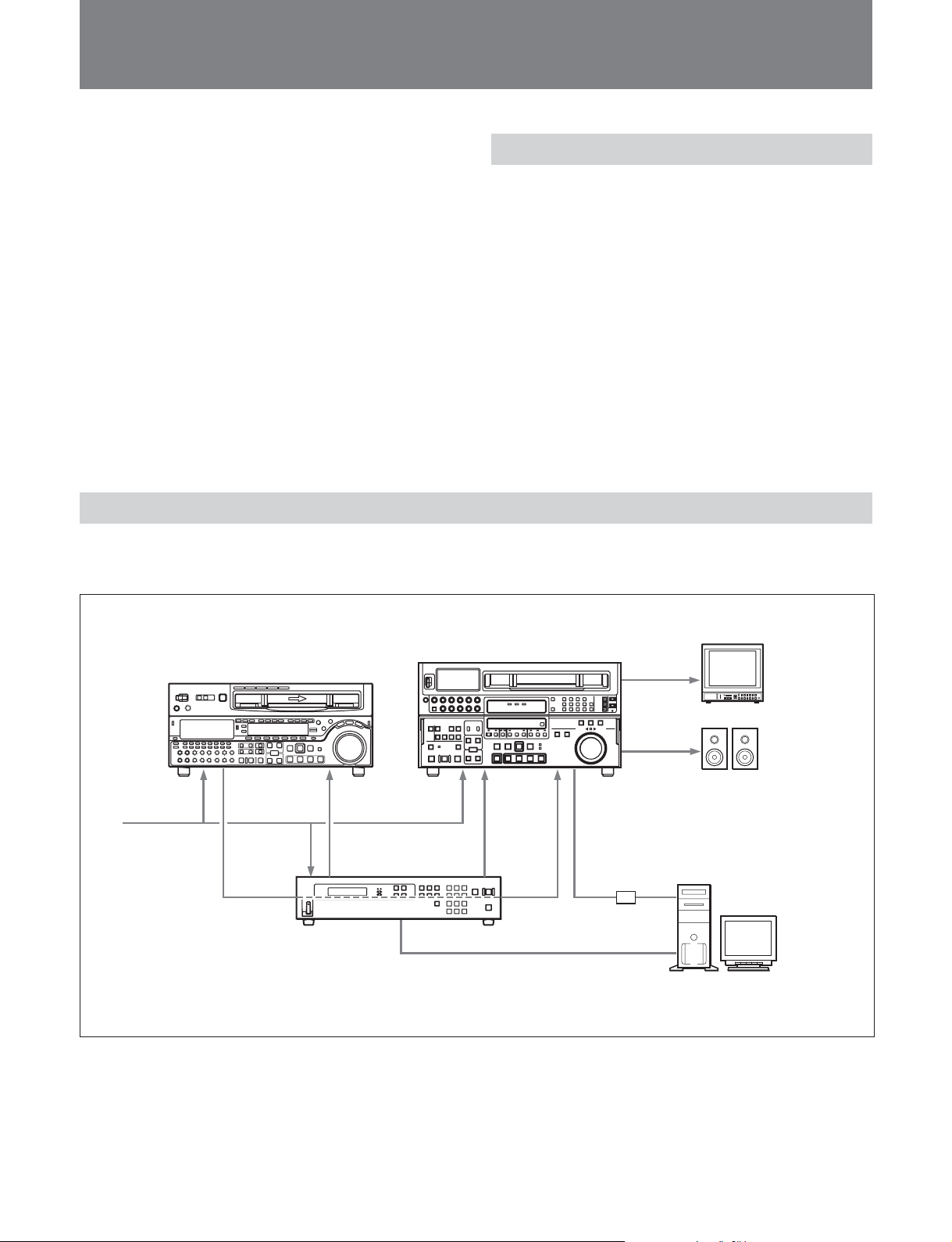
System Configuration
The following figure shows a system configured
around this unit.
Features
This unit has the following features.
•Time-adjusted tapes can be created using two VTRs.
Time-adjustment range: ±5%
Steps: 0.1%
•Time can be adjusted without impairing closed
caption data on material tapes.
•Audio can be output without changing pitch.
•The unit can be controlled from a computer using a
graphical interface. (It is necessary to install the
supplied Program Play Box Control Software.)
•The unit can be mounted in a standard EIA 19-inch
rack. (It is necessary to use the optional RMM-30
Rack Mount Rail and SXA-2U Rack Mount Bracket.)
Player
SDI
Reference video
signal
RM-PP1 Program
Play Box (this unit)
a) Use a convertional video capture unit.
Recorder
RS-422A RS-422A
RS-232C
Video capture unit
Video monitor
Audio monitor
a)
Computer (Program Play Box
Control Software installed)
1
Page 5
Names and Locations of Parts
Names and Locations of Parts
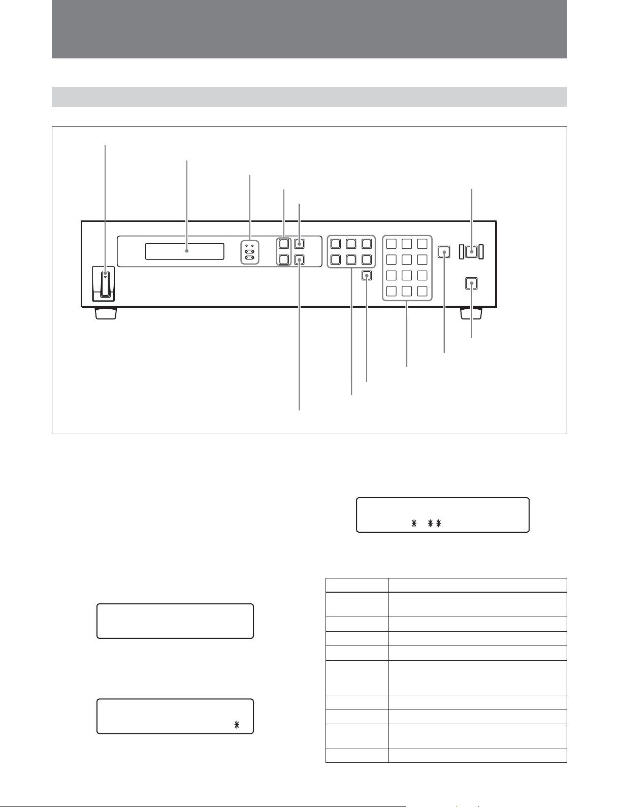
Front Panel
1 POWER switch
2 LCD display window
3 Status indicators
4 J/j buttons
5 MENU button
qs AUTO EDIT button
1 POWER switch
When pressed on the ON side, starts this unit and
lights the LCD display window.
2 LCD display window
Displays edit points, menus, the status information
(including the initialization message), the operation
mode, and error messages.
•Edit points display
Edit points set or being set are displayed as shown in
the figure below.
IN
OUT
00 : 00 :00 : 00
00 : 05 :00 : 00
<
•Menu display
The setup menu item set or being set is displayed as
shown in the figure below.
REF SELECT
REF I NPU
For more information about the setup menu, see page 12.
T
2
0 PREVIEW/REVIEW button
9 Keypad buttons
8 DELETE button
7 IN/OUT/DUR buttons
6 ENTER button
•Status information
A message informing the status of this unit is
displayed as shown in the figure below.
Program Play Box
Ver
The lower row shows the following messages
depending on the status.
Message Status
INITIALIZE The settings of this unit are being
Ver 1.00
ABORT Edit operation stops.
Edit During an edit
Ready Ready for an edit (The edit points,
Review During review
Preview During preview
OK Edit, review or preview operation
Error An error occurs.
a) System software version of the unit
a)
.
initialized.
Usual state
duration or time adjustment rate have
been set correctly.)
completes.
qa STOP button
Page 6

•Computer remote mode display
When this unit is under computer remote control, the
upper row in the LCD display shows the message as
shown in the figure below.
Remo t e Mode -R-S
(status
Communication states between this unit and the
computer are also shown at the right end of the upper
row as follows.
–R: receiving data from the computer
–S: sending data to the computer
•Error message
When an error occurs, the lower row shows “Error”.
Pressing the J or j button shows the error code and
message.
)
Progra m PlayBox
E111 CUEUP TIMEOU
For more information about error codes and messages, see
page 15.
3 Status indicators
Light under the following conditions.
ALARM: When an error occurs
ABORT: When an editing operation is aborted
(including aborts after errors)
DF (drop-frame): When the recorder timecode
setting is drop-frame mode
NDF (non-drop frame): When the recorder
timecode setting is non-drop frame mode
LOCAL: When this unit is being controlled from its
front panel
REMOTE: When this unit is being controlled from a
computer
T
7 IN (In point)/OUT (Out point)/DUR (duration)
buttons
Used to set In and Out edit points and durations. The
buttons in the upper row set player edit points and the
buttons in the bottom row set recorder edit points.
8 DELETE button
Deletes an edit point. Flashes when an invalid edit
point has been set.
9 Keypad buttons
Used to set edit points and make setup menu settings.
Numeric buttons (0 to 9): Enter edit point values
CLR (clear) button: Clears a value that has been
entered, and moves to a higher level in the setup
menu.
SET button: Confirms an edit point or setup menu
setting. When pressed after an error, clears the
display of the error message.
0 PREVIEW/REVIEW button
When pressed after edit points have been set or after
the completion of editing, executes a preview or
review of the results. Lights during the preview or
review.
qa STOP button
Stops and editing operation.
Lights, flashes, or goes out according to the state of
external synchronization.
For details, see page 6.
qs AUTO EDIT button
Flashes when edit points have been set correctly and
editing is possible. Starts the edit if pressed while
flashing. Lights while an edit is in progress.
4 J/j buttons
Used increment and decrement time adjustment rate
setting values. In the setup menu, used to move
between items and change setting values.
5 MENU button
Used to display the setup menu and change settings.
6 ENTER button
Used to move in the setup menu and to confirm setting
values.
3
Page 7
Names and Locations of Parts
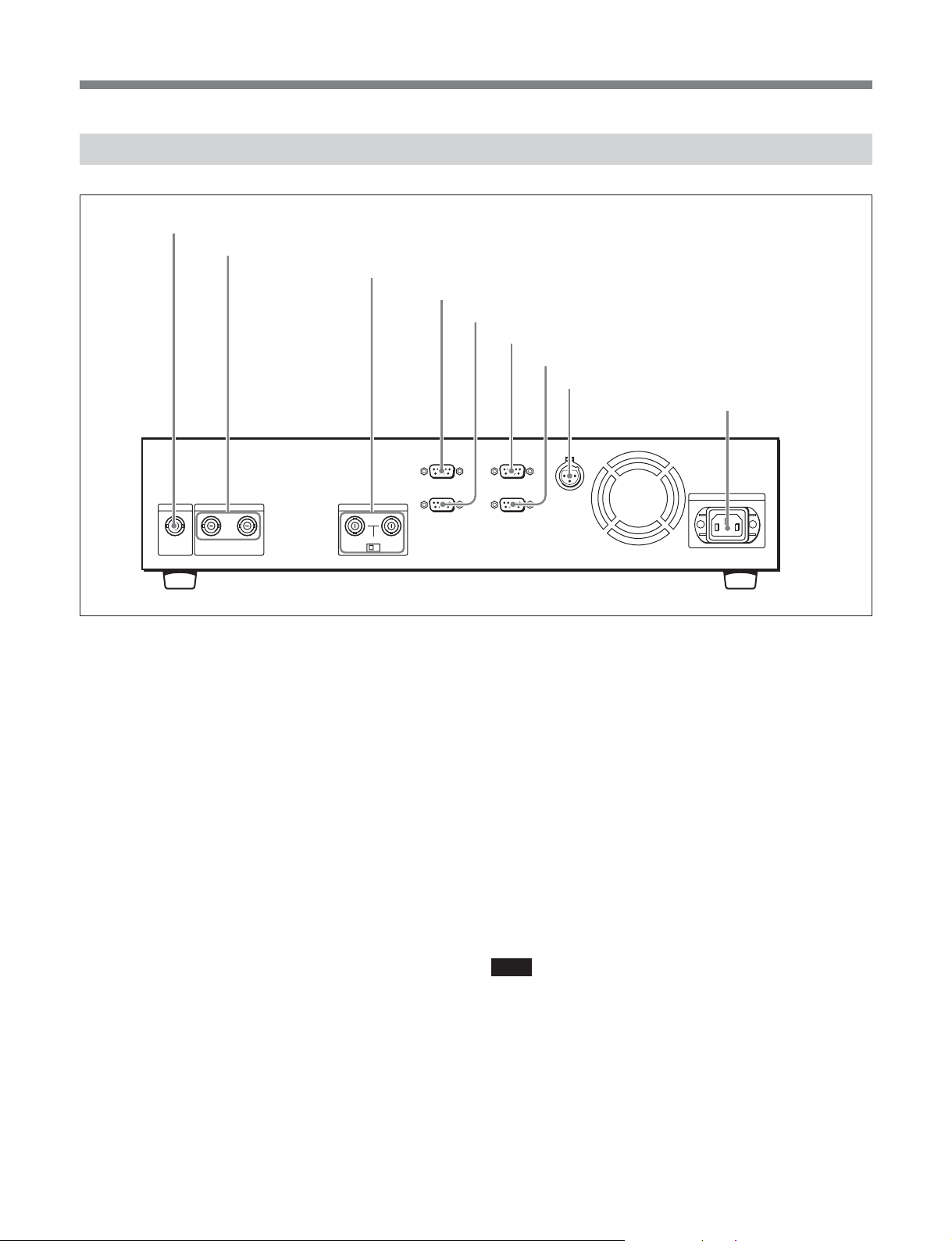
Rear Panel
1 SDI IN connector
2 SDI OUT 1 and 2 connectors
3 REF IN connectors and 75 Ω termination switch
4 PLAYER REMOTE connector
5 RECORDER REMOTE connector
6 REMOTE IN (RS-232C) connector
7 RS-232C connector
8 TC OUT connector
9 AC IN connector
1 SDI IN (SDI input) connector (BNC type)
Inputs SDI signals (D1 format) from the player.
2 SDI OUT (SDI output) 1 and 2 connectors (BNC
type)
Output SDI signals (D1 format) to the recorder.
Connectors 1 and 2 output the same signals.
3 REF IN (SD reference video signal input)
connectors (BNC type) and 75 Ω termination switch
As reference video signals, input video signals with
chroma burst or black and white video signals. Set the
75 Ω termination switch to OFF to bridge connect the
two connectors.
4 PLAYER REMOTE connector (D-sub 9-pin,
RS-422A)
Connect to the player’s 9-pin remote connector.
5 RECORDER REMOTE connector (D-sub 9-pin,
RS-422A)
Connect to the recorder’s 9-pin remote connector.
6 REMOTE IN (remote input) (RS-232C)
connector (D-sub 9-pin)
Use this connector to control this unit from a
computer.
7 RS-232C connector
Use this connector to connect this unit to a computer,
for example to perform self diagnostics.
8 TC OUT (timecode output) connector (XLR
3-pin, male)
When using a closed caption encoder as an external
device, connect it to this connector. This connector
does not need to be connected to the LTC input
connector of the VTR.
Note
Except during editing, this unit creates LTC timecode
from VITC included in the SDI input signal. There, if
VITC cannot be detected in the SDI input signal,
nothing is output from the TC OUT connector.
9 AC IN (AC power input) connector
Connect to AC power.
4
Page 8
Preparations
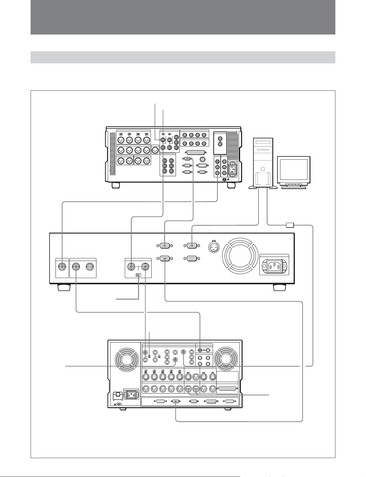
Connections to External Devices
The figure below illustrates example connections with
an MSW-A2000 (player) and a DVW-A500 (recorder).
Reference video signal
75 Ω termination switch: OFF
MSW-A2000 (player)
a)
SDI IN SD REF IN
SDI OUT
75 Ω termination
switch: OFF
a)
REF. VIDEO
INPUT
SD REF OUT
REF.VIDEO
INPUT
a)
PLAYER
REMOTE
RECORDER
a)
75 Ω termination
switch: ON
REMOTE
SERIAL V/A INPUT
REMOTE
1-IN(9P)
SDI OUT
RS-232C
b)
REMOTE IN(RS-232C)
Computer (Program
Play Box Control
Software installed)
d)
Video capture unit
(not supplied)
RM-PP1
(this unit)
a)
Video monitor
COMPOSITE3
VIDEO OUTPUT
REMOTE 1-IN(9P)
a) 75 Ω coaxial cable with BNC connectros
b) 9-pin remote control cable
c) XLR cable
d) 9-pin remote control cable (RS-232C, cross cable)
DVW-A500
(recorder)
COMPOSITE2
VIDEO OUTPUT
MONITOR
OUT PUT
c)
Audio monitor
b)
5
Page 9
Preparations
Connections to digital devices
Connections to a computer
This unit can be remotely controlled by a computer on
Connect this unit to a player equipped with an SDI
output connector and a 9-pin remote connector, and to
a recorder with an SDI input connector.
which the Program Play Box Control Software has
been installed.
Use a 9-pin remote control cable (RS-232C, cross
cable) to connect a computer to this unit.
Refer to the online help supplied with the Program Play Box
Control Software for more information about controlling
this unit from a computer.
Reference Video Signals
Internal reference video signal generator and external synchronization
SDI output signals synchronize with an external
reference video signal or with SDI signals.
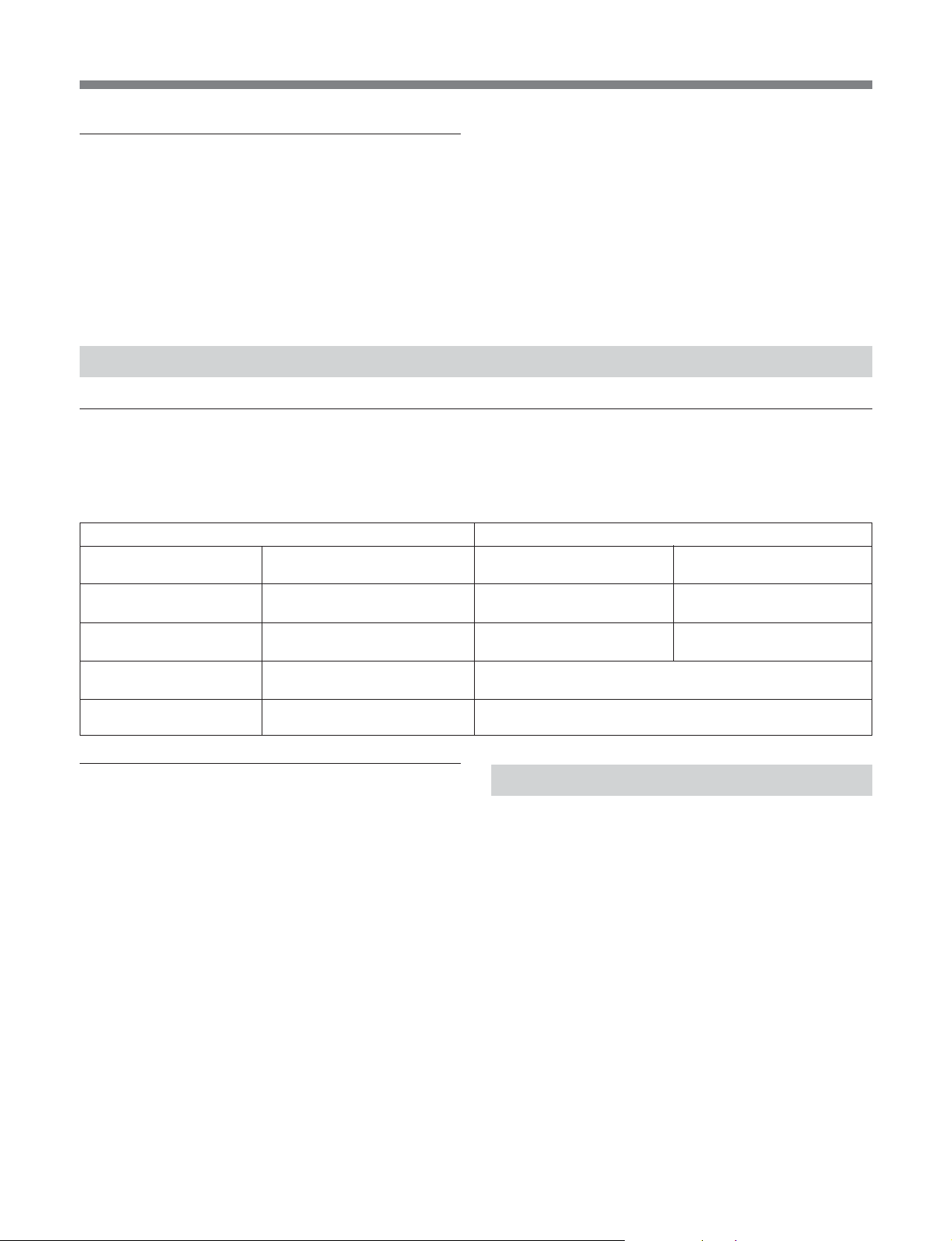
External synchronization is decided as follows,
Signal input REF SELECT setting
External reference video
input
Valid Valid Synchronized with the
None Valid Synchronized with the SDI
Valid None Synchronized with the external REF signal.
None None Not synchronized.
SDI video input When REF SELECT is set to
according to the setting of the setup menu REFSELECT item (see page 12) and the combination of
input signals.
REF INPUT
external REF signal
input signal
The RM-PP1 outputs a freeze picture and mute audio.
The RM-PP1 outputs a freeze picture and mute audio.
When REF SELECT is set to
SDI INPUT
Synchronized with the SDI
input signal
Synchronized with the SDI
input signal
Checking the status of external
synchronization
You can check the status of external synchronization
on this unit by checking the STOP button, which is lit,
not lit, or flashing as follows.
Lit: The SDI output signal is synchronized with the
external reference video signal.
Not Lit: The SDI output signal is synchronized with
the SDI input signal.
Flashing: No SDI input. or SDI output is invalid.
6
Setup
All settings on this unit can be made via the setup
menu. Setup menu settings are backed up in
nonvolatile memory.
The setup menu contains the following setting
categories.
•Settings related to synchronization
•Settings related to VTR connections
•Settings related to recording modes
•Settings related to time adjustment methods
•Settings related to SDI
•Settings related to the addition of ancillary data to
SDI output signals
•Settings related to limits on remote control by
computer
•Other settings
For details about the setup menu, see page 12.
Page 10
Time Adjustment Editing
Overview
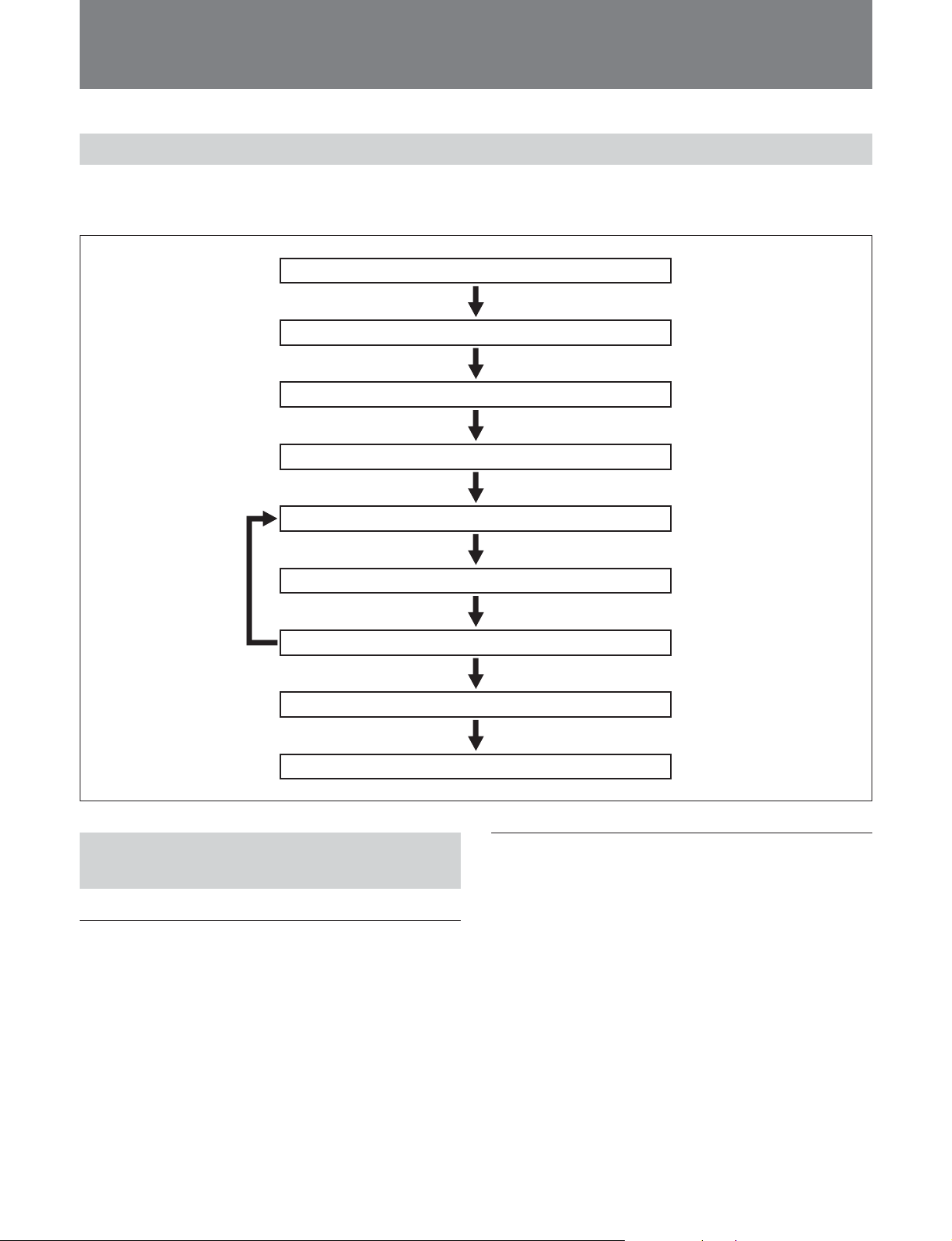
The following shows the flow of time adjustment
editing operations.
Set up equipment (see below)
Set parameters (see next page)
Select edit mode (see next page)
Select DF or NDF (see next page)
Set editing points and time adjustment rate (see next page)
Preview edit segments (see page 10)
Modify edit points and time adjustment rate (see page 10)
Execute auto edit (see page 10)
Check editing results (review) (see page 10)
Setting Up the Player and Recorder
Setting up the player
•Select DF (drop-frame) or NDF (non-drop frame),
according to the type of timecode recorded on the
tape.
•Put the player into 9-pin remote operation mode, so
that it can be controlled from this unit.
Setting up the recorder
•Select SDI as the input video signal
•Select DF or NDF as the type of timecode to be
recorded.
•Put the recorder into 9-pin remote operation mode, so
that it can be controlled from this unit.
7
Page 11
Time Adjustment Editing
Setting Time Adjustment Parameters
Make the following settings in the setup menu.
•Audio pitch correction reference channel
Under AUDIO LAG CALC (see page 13) select the
channel to use for audio pitch correction reference
(data to extract the pitch).
Note
If you make reference channels the same as audio
correction target channels (for example, by selecting
channel 1 as the reference channel for channel 1, and
channel 2 as the reference channel for channel 2), then
channels may be out of phase for data such as stereo
data. To prevent this, select the same reference channel
for all target channels (for example, by selecting
channel 1 as the reference channel for channels 1 to 4).
•VITC insertion line
Set the VITC insertion line for SDI signals output from
this unit to the recorder for VITC 1 and VITC 2 (VITC
POS-1 and VITC POS-2 on page 12).
•Blanking line
Turn vertical blanking on and off for each line in SDI
video signals output from this unit to the recorder
(BLANK LINE on page 13).
Selecting the Edit Mode and DF/ NDF
Under REC MODE in the setup menu, select assemble
mode or insert mode.
Under DROP FRAME MODE in the setup menu,
select drop-frame or non-drop frame for the timecode
read from the player and for the timecode of the
material.
Note
The DF or NDF setting affects the number of frames
inserted or removed in time adjustment editing as well
as time adjustment rate calculations. Editing cannot be
executed if the frame count mode selected here differs
from the frame count mode found on the tape in either
the player or the recorder.
Setting Edit Points
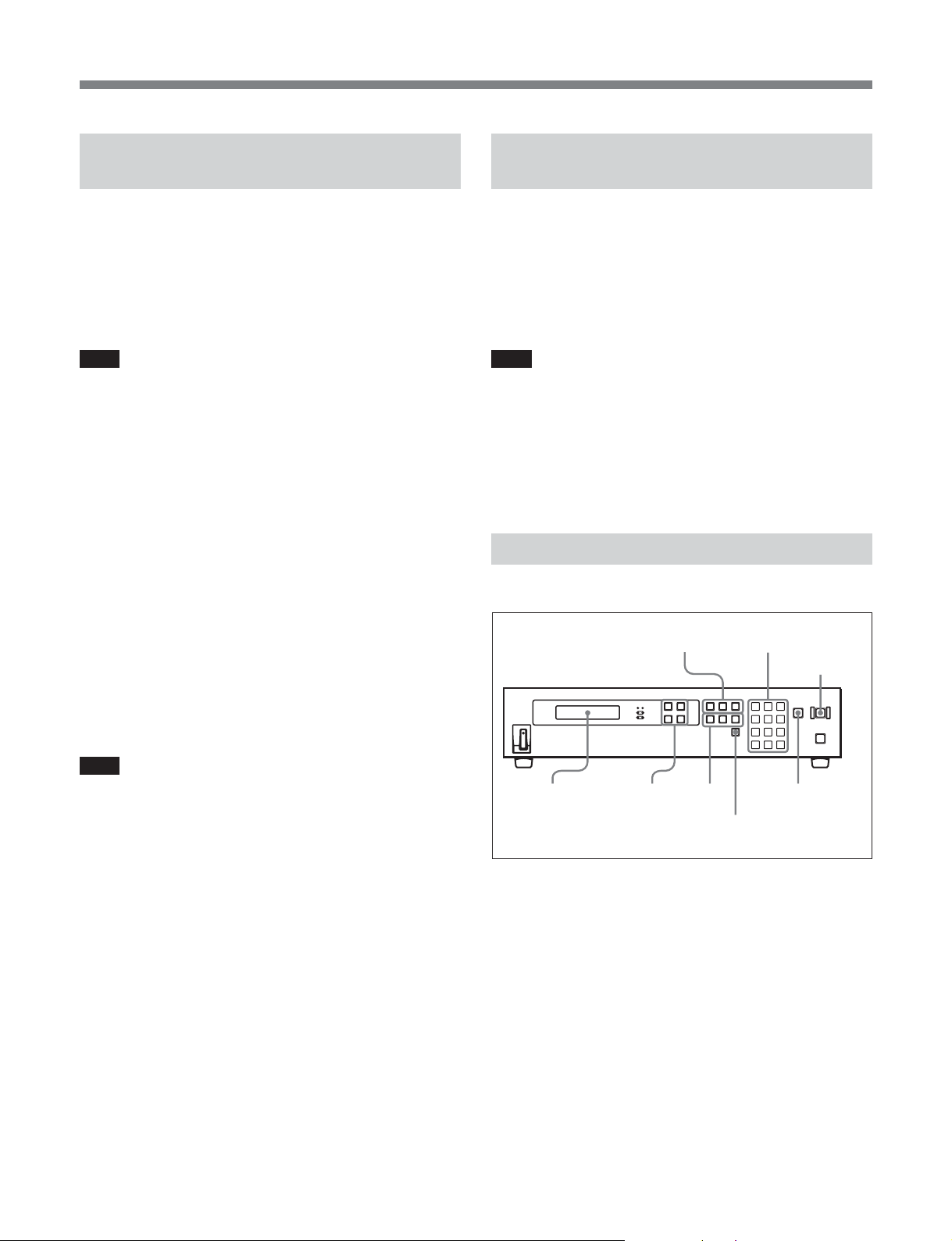
See also “To enter edit points in another way” on page 9.
3,4,5,62
AUTO
EDIT
button
Note
In the time adjustment processing performed by this
unit, signals are inserted and deleted in units of fields.
Therefore, when material which has inserted data into
vertical blanking intervals is compressed, data
dropouts and discontinuities will result. You need to
turn blanking on if you do not wish to leave
incomplete data after time adjustment processing. Note
that the processing performed by this unit does not
cause data dropouts or discontinuities for closed
captions and VITC recorded in the editing results.
8
1,2,3,5
1,4,6 6
DELETE
button
PREVIEW/
REVIEW button
1 Under the setup menu item DUR INPUT STYLE
(see page 12), set the time adjustment rate input
method as follows.
TIME: Specify the time adjustment rate by
specifying the timecode of the player and
recorder In and Out points.
RATE: Specify the time adjustment rate as a
numeric value (%).
Page 12
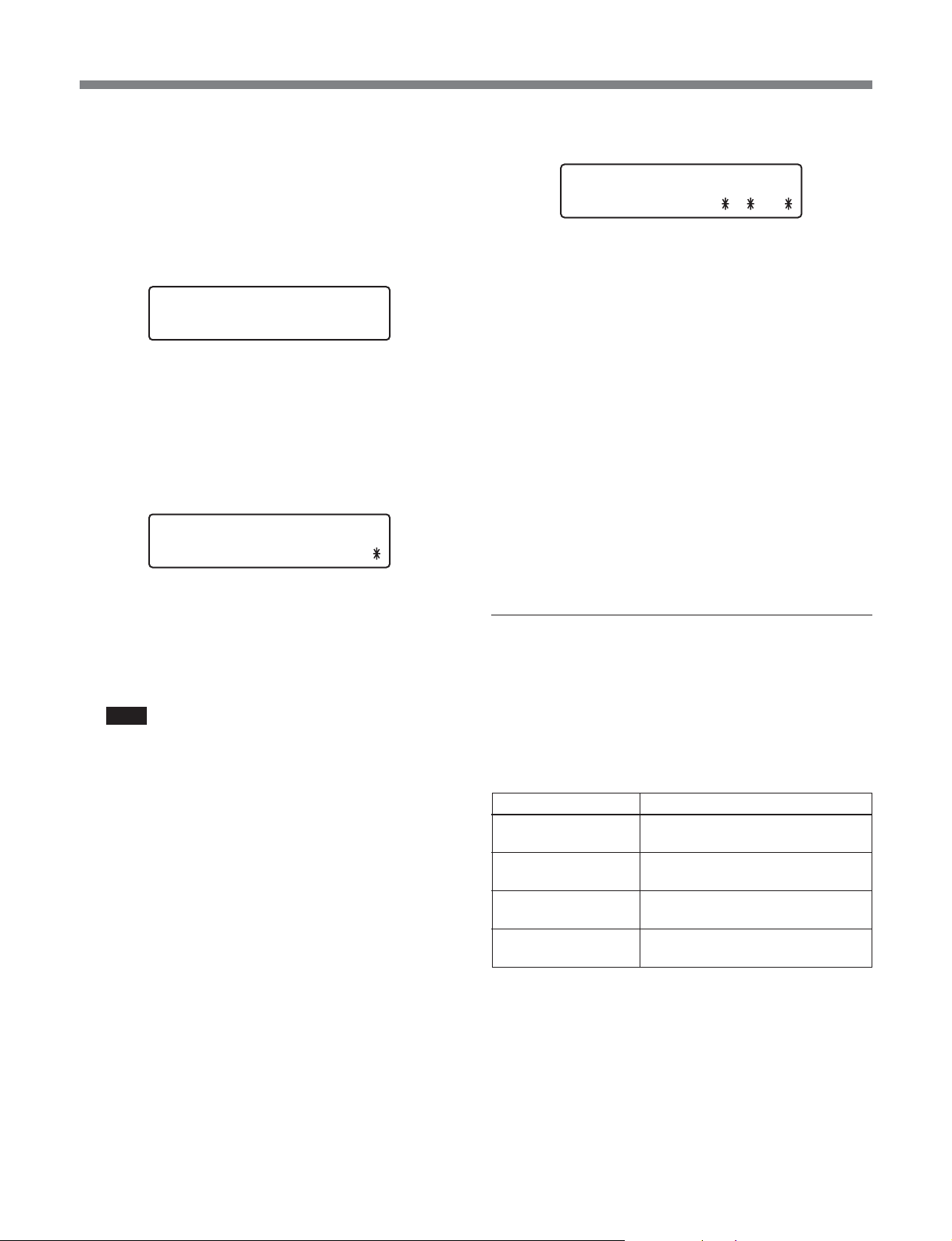
2 Press the IN, OUT, or DUR button for the player.
Example: when entering the time adjustment rate
The pressed button begins to flash, and “<”
appears in the upper row timecode display (for the
player) in the LCD display window.
Example: before entering a value
IN
IN
--:--:--:--
--:--:--:--
<
3 Enter a numeric value the numeric buttons in the
keypad.
While the value is being entered, the “<” in the
timecode display changes to “*”.
Example: when entering the recorder duration
IN
DUR
00 : 00 :00 : 00
--:05:00 : 00
4 Press the ENTER button or the keypad SET
button.
IN
R T
To enter the recorder duration as a time
adjustment rate
If you selected RATE in step 1, you can specify
the duration with a time adjustment rate.
Press the DUR button, enter + (add time) or –
(subtract time) with the J and j buttons, and enter
a time adjustment rate with the keypad numeric
buttons.
When the edit points and duration have been set
correctly, the IN, OUT, and DUR buttons for the
player and recorder all light, and the AUTO EDIT
button lights.
If there is an invalid setting
The DELETE button starts flashing. Delete or modify
the edit point setting (see next page).
00 : 00 :00 : 00
+.1
%
To enter edit points in another way
The value is confirmed and the button pressed in
step 2 lights.
Note
Depending on the DF/NDF setting for the player,
the specified timecode may not exist. Check that
the DF/NDF setting is correct by checking DROP
FRAME MODE in the setup menu.
5 Repeat steps 1 to 3 to set the other edit point or the
duration.
When two among the In point, Out point, and
duration are set, the remaining item is set
automatically.
6 If you selected TIME in step 1, use two buttons
from among the IN, OUT, and DUR buttons for
the recorder to set the recorder edit points or
duration. If you selected RATE in step 1, use the
DUR button for the recorder and either the IN or
OUT button to set a time adjustmnet rate (%) and
the recorder In or Out point.
By pressing an IN or OUT button with the ENTER
button held down, you can enter the current timecode
of the VTR as an edit point.
The IN and OUT buttons in the upper row are for the
player, and the IN and OUT buttons in the lower row
are for the recorder.
Edit point button Result
Player IN button The current player timecode is set
as a player In point.
Player OUT button The current player timecode is set
as a player Out point.
Recorder IN button The current recorder timecode is
set as a recorder In point.
Recorder OUT button The current recorder timecode is
set as a recorder Out point.
9
Page 13

Time Adjustment Editing
To check edit points on the VTR after
entering them
1 Load cassettes in the player and recorder, and set
their 9-pin remote control modes to on.
2 With an IN or OUT button held down, press the
PREVIEW/REVIEW button.
The VTRs are cued up to the entered edit points as
follows.
Player IN button pressed: The player is cued up
to the timecode position entered as a player In
point.
Player OUT button pressed: The player is cued
up to the timecode position entered as a player
Out point.
Recorder IN button pressed: The recorder is
cued up to the timecode position entered as a
recorder In point.
Recorder OUT button pressed: The recorder is
cued up to the timecode position entered as a
recorder Out point.
Deleting and Modifying Edit Points
Note
Settings that were entered automatically cannot be
deleted or modified.
Preview
After you have finished setting the edit points, and
with the AUTO EDIT button flashing, press the
PREVIEW/REVIEW button.
You can monitor the video and audio on the monitor
connected to the recorder.
To stop the preview, press the STOP button.
Note
Recorder OUT points cannot be previewed in assemble
mode (when REC MODE in the menu is set to
ASSEMBLE).
Executing an Auto Edit
Time-adjustment editing starts when you press the
flashing AUTO EDIT button.
The amount of memory required by this unit varies
depending on the number of frames added or removed.
If the memory requirements exceed the amount of
memory installed in the unit, the unit automatically
divides the segment by setting additional edit points.
Note
In compression editing, this unit first stores all of the
frames to be removed and then starts the recorder.
When the number of frames is large, considerable time
(up to about 90 seconds) may be required after the
player starts running until the recorder starts recording.
To delete edit point settings
With the DELETE button held down, press the IN,
OUT, or DUR button, depending on the setting that
you want to delete.
Depending on the button that you pressed, the In point,
Out point, or duration is deleted, along with any
automatically entered setting. The button for the
deleted edit point or duration goes out.
To modify edit point settings
Press the IN, OUT, or DUR button, depending on the
setting you want to modify.
The pressed button starts flashing, and you can reset
the edit point or duration.
10
Example: Reducing 30 minutes of material in non-
drop frame mode by 5%
The number of frames to be removed is 2700, so the
recorder remains on standby for 90 seconds until the
data for this number of frames has been stored.
To perform this edit without splitting the job, the
number of frames that can be added or removed should
be up to 2850.
To check edit result (review)
When editing finishes, press the PREVIEW/REVIEW
button. The edited segment is played back, and you
can monitor the editing results on the monitor
connected to the recorder.
Page 14
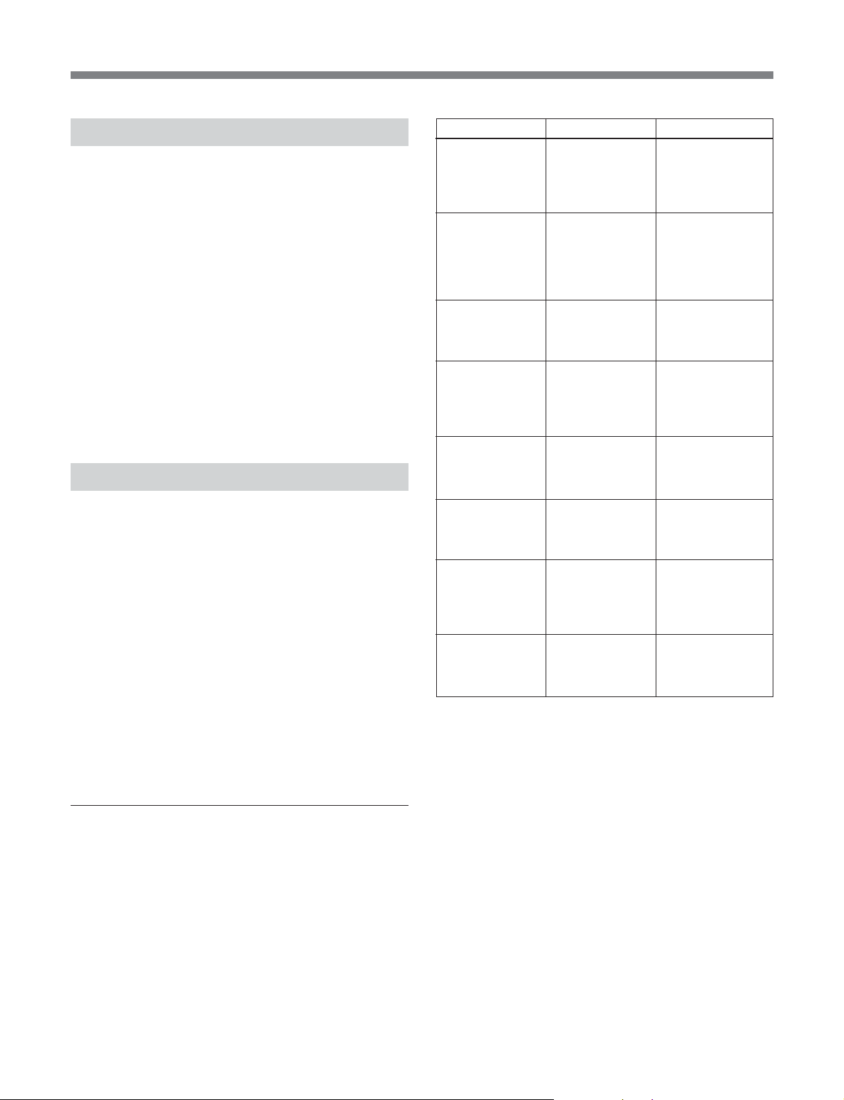
Control From a PC
By connecting this unit’s REMOTE IN (RS-232C)
connector to the RS-232C port on a PC with the
Program Play Box Control Software installed, you can
control editing on this unit from the PC.
During remote control from the PC, the LOCAL
indicator on the front panel of this unit goes out, and
the REMOTE indicator lights. By setting KEY
INHIBIT under REMOTE/LOCAL MODE in the
setup menu to ON (see page 13), you can disable
operations from the front panel while the unit is under
remote control.
For more information about using the Program Play Box
Control Software, refer to the online help supplied with the
software.
Editing Errors
Under the following conditions, editing may be
interrupted by errors. If an error occurs, determine the
probable cause, remedy it, and try again.
The following are common causes of errors.
•The drop-frame mode setting of this unit is not the
same as the drop-frame mode setting of the material
or the recording cassette.
•The player or recorder is not in 9-pin remote control
mode.
•This unit is not connected properly to other devices.
(Use menu item CONNECTION STATUS to check
signal connections. For details, see the next section
“To check signal connections”.)
Check item Status Steps to take
PLY-VTR
CONNECTION
(connection to
player)
REC-VTR
CONNECTION
(connection to
recorder)
SDI INPUT
SIGNAL
EXT REF INPUT NG!!, NO SIGNAL Check the external
REC-VTR
RECINHIBIT
PLY-VTR
9pinREMOTE
REC-VTR 9pin
REMOTE
REC-VTR REF
INPUT
NG Check the 9-pin
NG Check the 9-pin
NG!!, NO SIGNAL Check the SDI
NG!!, REC
INHIBIT
!!, LOCAL MODE Check the player 9-
!!, LOCAL MODE Check the recorder
NG!!, REF
MISSING
connection cable
from RM-PP1 and
the player POWER
ON switch.
connection cable
from RM-PP1, and
the recorder
POWER ON
switch.
input cable from
player SDI out to
RM-PP1 SDI input.
reference video
signal input and
cable connection to
RM-PP1.
Check the recorder
and cassette
RECINHIBIT
setting.
pin remote control
mode before edit,
preview, review.
9-pin remote
control mode
before edit,
preview, review.
Check the recorder
REF INPUT item
and REF input
connection.
See page 15 for more information about error messages.
To check signal connections
Use the CONNECTION STATUS item of the menu to
check the status of connections. If the status of a
connection is as shown below, take the indicated steps
to remedy it.
See the next page for more information about menu
operations.
11
Page 15
Setup Menu
Setup Menu Operations
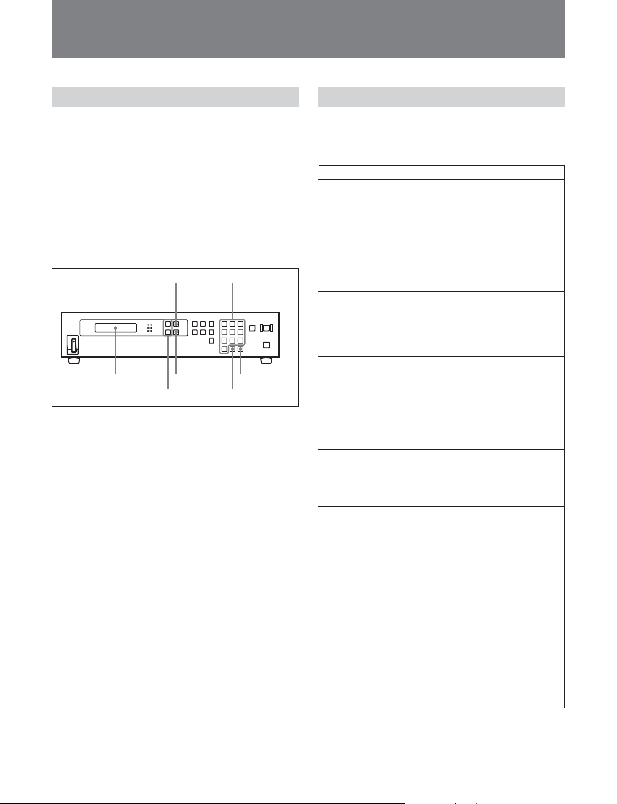
To display the setup menu
Press the MENU button. The button lights and the
menu appears in the LCD display window.
Operations in the setup menu
The upper row in the LCD display window shows the
menu item name, and the lower row shows the setting
of the item.
MENU button
LCD display window
ENTER button
J/j buttons
To display another item or setting
Press the J button to display the next item or setting.
Press the j button to display the previous item or
setting.
When you select a new setting for an item, an asterisk
(*) appears in the setting display. To return to the
original setting, press the CLR button in the keypad.
To enter a setting value directly
Use the numeric buttons in the keypad to enter settings
directly. To add a minus sign, press the J button. To
add a plus sign, press the j button.
To return to a higher level
If the setting has two levels, you can return from the
lower to the higher level by pressing the CLR button
on the keypad.
To confirm a setting
When the desired setting appears in the LCD display
window, confirm it by pressing the ENTER button or
the SET button on the keypad. The asterisk (*)
disappears from the setting display.
Numeric buttons
SET button
CLR button
Menu Items
The follow table shows the items in the setup menu.
Settings marked with asterisks (*) are the factory
defaults.
Item Setting
REF SELECT
Select sync signal
Y-ADD
Select Y-Add filter
operation mode
AUDIO CH5-CH8
Select whether or
not to add audio
data CH5 to CH8
in the SDI H-ANC
region
VITC POS-1
Select insert line
for VITC added to
output signal
VITC POS-2
Select insert line
for VITC added to
output signal
DUR INPUT
STYLE
Select recorder
side duration input
method
VTRPARASET
Select whether or
not to
automatically set
parameters (preroll
time, edit delay)
for the recorder
and player
PREROLL TIME
Preroll time setting
EDIT DELAY
Edit delay setting
ABORT BEEP
Select whether to
beep when a time
adjustment
operation is
aborted
*REF INPUT: Input signal to SD REF
IN connector.
VIDEO INPUT: Input signal to SDI IN
connector.
*ON: When even and odd fields are
reversed because of signal addition
or removal, perform Y-ADD filter
processing.
OFF: Do not perform Y-ADD filter
processing.
*ON: Add.
OFF: Do not add.
Setting value: *12 to 20
Setting value: *12 to 20
*TIME: Input time.
RATE: Input time adjustment rate (%),
relative to normal speed.
Up to 2 decimal places can be input
(Example: ±X.XX%).
*AUTO: Set automatically to the
default VTR parameters.
MANUAL: Set manually
Setting value: 30 to *150 to 270 frames
(30-frame units)
Setting value: 1 to *5 to 10 frames
*OFF: Do not beep.
ON: Beep until a button is pressed.
3SEC: Beep for 3 seconds.
To hide the setup menu
Press the MENU button again.
12
Page 16
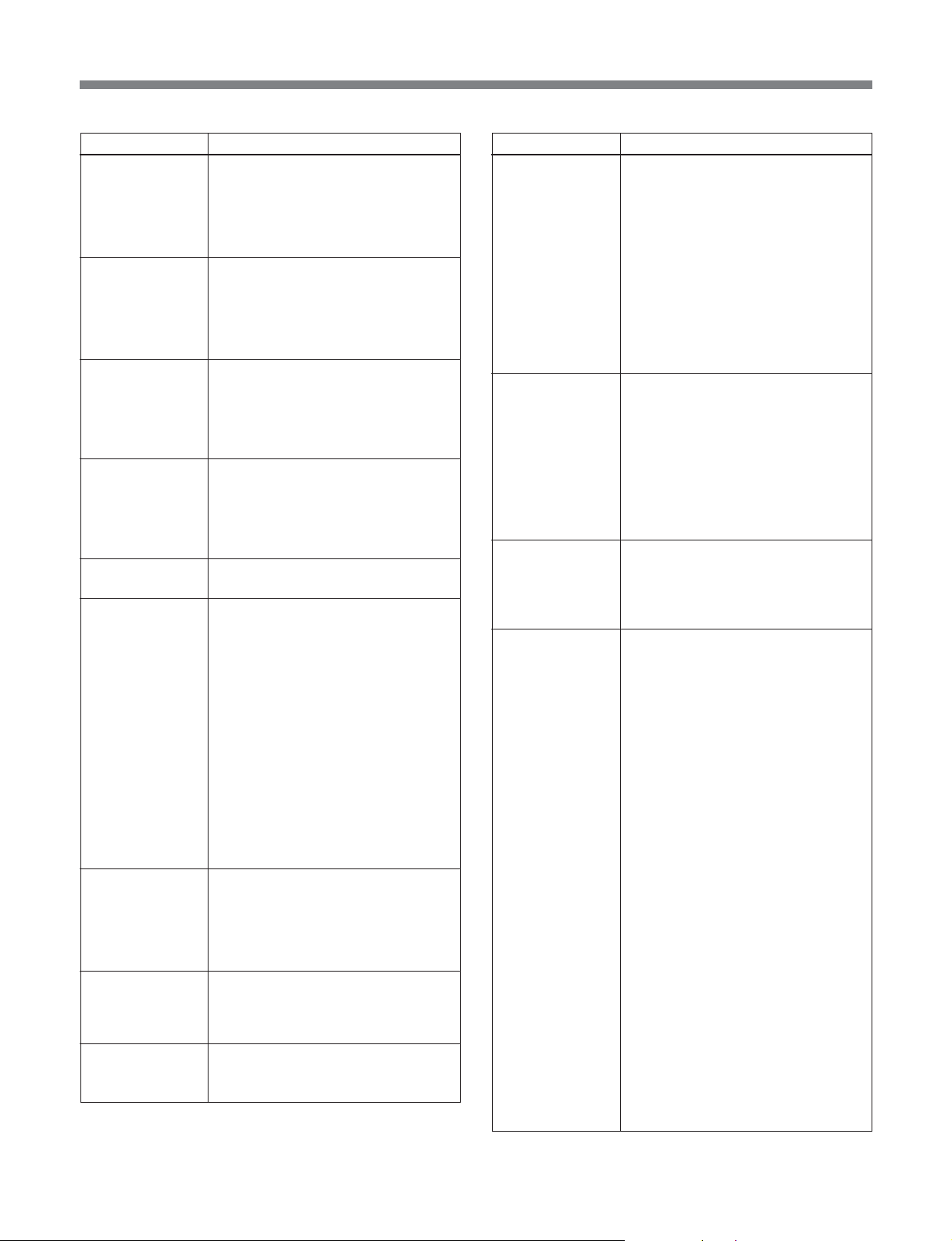
Item Setting
REM COM RATE
Set
communications
speed for
REMOTE IN (RS232C) connector
RS232C COM
RATE
Set
communications
speed for RS232C connector
PLAYER DF
MODE
Select the same
frame count mode
(DF or NDF) as
that of the material
RECORDER DF
MODE
Select the same
frame count mode
(DF or NDF) as
that of the material
REC MODE
Select edit mode
AUDIO LAG
CALC
Select reference
channel for pitch
correction (channel
from which to
extract pitch data)
CC READ
Select whether or
not to read closed
caption data
CC WRITE
Select where to
write closed
caption data
CC WRITE LINE
Select lines when
writing to VANC
Setting value: 9.6, 19.2, *38.4,
57.6 Kbps
Setting value: 9.6, 19.2, *38.4,
57.6 Kbps
Select *DF or NDF.
Select *DF or NDF.
*INSERT: Insert mode
ASSEMBLE: Assemble mode
LAG CALC CH1: Select one of *CH1,
CH2, CH3, CH4
LAG CALC CH2: Select one of CH1,
*CH2, CH3, CH4
LAG CALC CH3: Select one of CH1,
CH2, *CH3, CH4
LAG CALC CH4: Select one of CH1,
CH2, CH3, *CH4
LAG CALC CH5: Select one of *CH5,
CH6, CH7, CH8
LAG CALC CH6: Select one of CH5,
*CH6, CH7, CH8
LAG CALC CH7: Select one of CH5,
CH6, *CH7, CH8
LAG CALC CH8: Select one of CH5,
CH6, CH7, *CH8
*21Line: Detect closed caption data
added to line 21 and perform time
adjustment processing.
VANC: Detect closed caption data
added to VANC and perform time
adjustment processing.
*21line: Output to line 21.
VANC: Output to VANC.
21line&VANC: Output to line 21 and
VANC.
Setting value: *9 to 19
Item Setting
BLANK LINE
Turn video signal
vertical blanking
on and off
REMOTE/LOCAL
MODE
Enable or disable
remote control via
RS-232C, and
lock or do not lock
the front panel of
this unit while
under remote
control
VERSION
Software version
display (CPU,
programmable
devices, DSPs)
CONNECTION
STATUS
connection status
display
ALL LINE
- - -: Specify the blanking for each
line separately.
*BLANK: Blank all lines regardless of
the settings of LINE 9 ... LINE 21.
THROUGH: Turn off blanking for all
lines regardless of the settings of
LINE 9 ... LINE 21.
LINE 9 ... LINE 21
Specify blanking for lines 9 to 21
separately.
*BLANK: Blank on.
THROUGH: Turn off blanking.
KEY INHIBIT: Lock (*ON) or do not
lock (OFF) front panel of this unit
when unit is under remote control.
REMOTE CONTROLL: Enable (*ON)
or disable (OFF) remote control of
editing operations.
KEYINHIBIT MODE: Lock all panel
operations on this unit (ALL
DISABLE), or enable the STOP
button only (*STOP key ENABLE).
SYS: Display CPU software version
DSP: Display DSP software version
(DSP1 to 4)
PLD: Display PLD software version
(PLD1 to 2)
PLY-VTR CONNECTION
OK: 9-pin remote communication is
good.
NG: No 9-pin remote communication
to player.
REC-VTR CONNECTION
OK: 9-pin remote communication is
good.
NG: No 9-pin remote communication
to recorder.
SDI INPUT SIGNAL
OK: SDI input signal is valid.
NG!!: NO SIGNAL’ SDI input signal
is no or invalid.
EXT REF INPUT
OK: EXT-REF input video signal is
valid.
NG!!, NO SIGNAL: EXT-REF input
video signal is no or invalid.
REC-VTR RECINHIBIT
OK: Recorder can record.
NG!!: REC INHIBIT: Recorder
cannot record.
NG!!: No communication to recorder.
PLY-VTR 9pinREMOTE
OK, REMOTE MODE: Player 9-pin
remote mode is on.
!!, LOCAL MODE: Player 9-pin
remote mode is off.
NG!!: No communication to player.
13
Page 17

Setup Menu
Item Setting
CONNECTION
STATUS
connection status
display
RECALL SETUP
Reset all settings
to the factory
defaults
REC-VTR 9pinREMOTE
OK, REMOTE MODE: Recorder 9-
pin remote mode is on.
!!, LOCAL MODE: Recorder 9-pin
remote mode is off.
NG!!: No communication to recorder.
REC-VTR REF INPUT
OK, REF LOCK: Recorder reference
input is good.
NG!!, REF MISSING: No reference
input to recorder.
NG!!: No communication to recorder.
RESET: Reset settings to factory
defaults.
14
Page 18
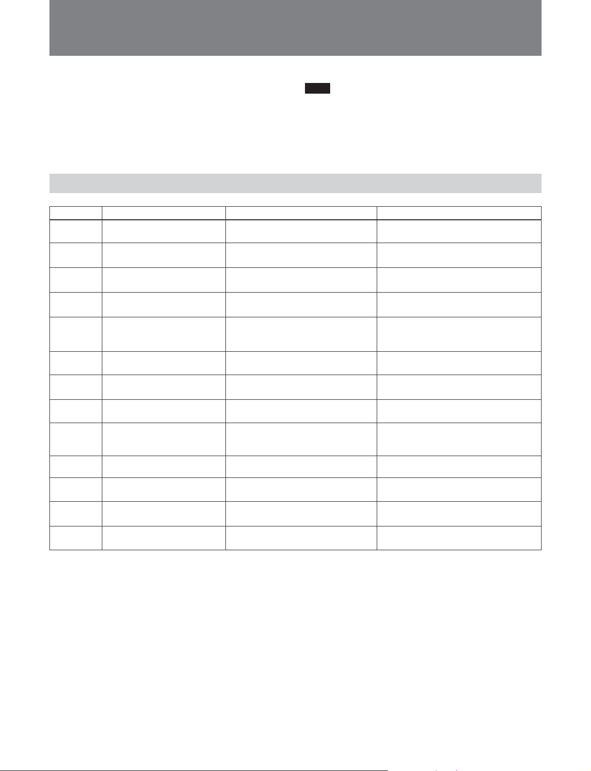
Error Messages
When an error occurs in this unit, “Error” appears in
the LCD display window. In this case, press the J or
j button to display the error code and message.
Pressing the CLR button in the keypad may recover
Note
Before contacting a Sony service representative, make
a note of the error code that appears at the start of the
error message.
from the error state.
Following is a list of error messages that may appear.
Hardware Errors
Error code Message Cause Steps to take
E001 MEMORY ERROR-1 CPU memory error The unit stops automatically. Contact a
Sony service representative.
E002 MEMORY ERROR-2 • Frame memory (SDRAM) error
• Invalid VIDEO memory setting
E003 LCD DEVICE ERROR • Harness unseated
• LCD device error
E004 SWITCH DEVICE ERROR • Harness unseated
• SWC board fault
E005 RS232 COMM ERROR • Cable fault
• Communications protocol setting
error
E006 RS232 DEVICE ERROR SIO device fault The unit stops automatically. Contact a
E007 RS422 COMM ERROR • Cable fault
• VTR RS-422 port fault
E008 RS422 DEVICE ERROR Fault in 9-pin control IC of this unit. The unit stops automatically. Contact a
E009 BackUP ROM ERROR EEPROM fault (power turned off
E010
E011 DSP DEVICE ERROR DSP fault The unit stops automatically. Contact a
E012 FAN SENSOR ERROR • Fan fault
E099 OTHER DEVICE ERROR — The unit stops automatically. Contact a
PLD DEVICE ERROR PLD fault The unit stops automatically. Contact a
during maintenance mode EEPROM
initialization processing)
• Fan stopped intentionally
The unit stops automatically. Contact a
Sony service representative.
The unit stops automatically. Contact a
Sony service representative.
The unit stops automatically. Contact a
Sony service representative.
Power the unit off and contact a Sony
service representative.
Sony service representative.
Power the unit off and contact a Sony
service representative.
Sony service representative.
Power the unit off and contact a Sony
service representative.
Sony service representative.
Sony service representative.
The unit stops automatically. Contact a
Sony service representative.
Sony service representative.
15
Page 19
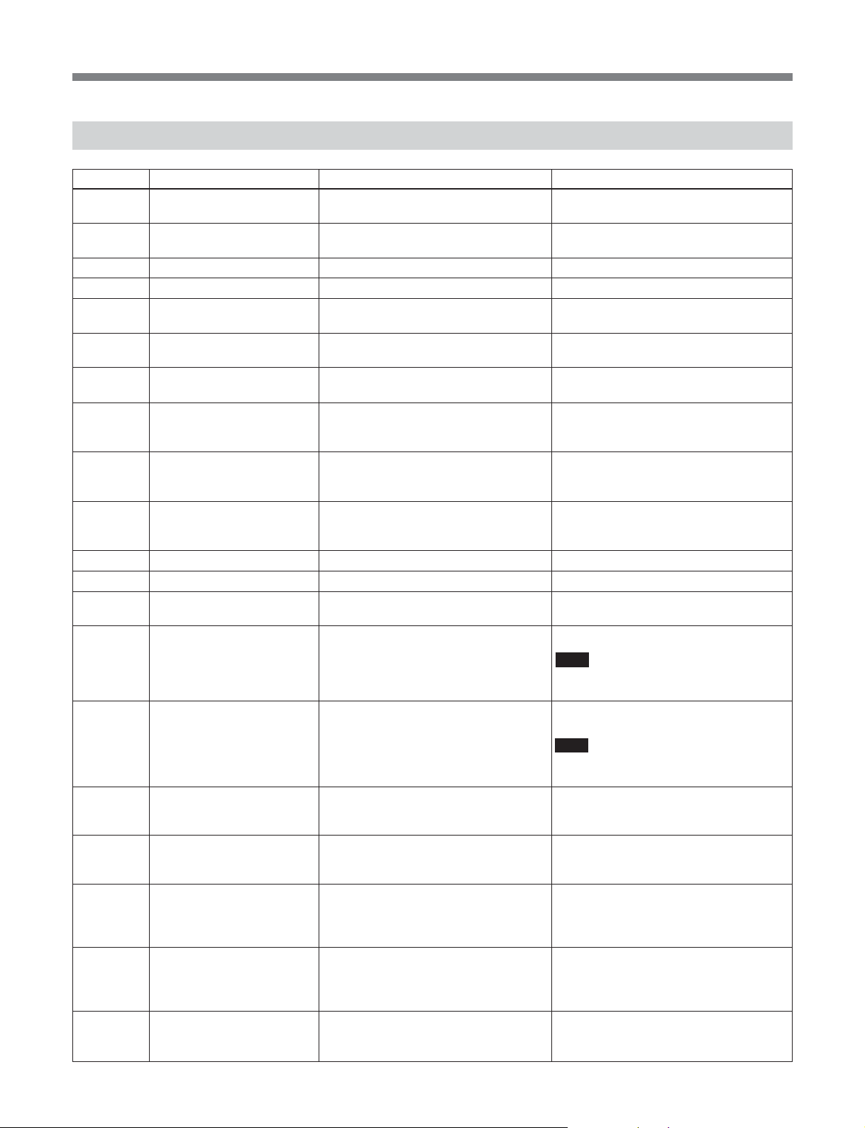
Error Messages
Editing Operation Errors
Error code Message Cause Steps to take
E101 P-REMOTE DISABLE Player 9-pin status sense data error.
Remote disable detected.
E121 R-REMOTE DISABLE Recorder 9-pin remote disabled. Check the recorder 9-pin remote control
E102 P-VTR HARD ERROR Player VTR hardware error detected. Check the player VTR state.
E122 R-VTR HARD ERROR Recorder VTR hardware error detected. Check the recorder VTR state.
E103 REF MISSING Reference signal connection trouble Check that reference video signals are
E123 R-REF MISSING Reference signal connection trouble Check that reference video signals are
E104 P-CASSETTE OUT
E124 R-CASSETTE OUT • Recorder 9-pin status sense data
E105 P-TAPE LENGTH SHORT • Player 9-pin status sense data
E125 R-TAPE LENGTH SHORT • Recorder 9-pin status sense data
E106 P-VTR CNTL T/O Player 9-pin control time out Check the player VTR.
E126 R-VTR CNTL T/O Recorder 9-pin control time out Check the recorder VTR.
E107 REC INHIBIT Recorder 9-pin status sense data
E108 PLY DEVICE TYPE ERR Player VTR device type error
E128 REC DEVICE TYPE ERR Recorder VTR device type error Check to make sure that the recorder
E109 P-DF MODE ERROR Operation error. Different DF mode
E129 R-DF MODE ERROR Operation error. Different DF mode
E110 P-SYNC PLAY MISS • VTR setting error
E130 R-SYNC PLAY MISS • VTR setting error
E111 P-CUEUP TIME OUT • VTR setting error
• Player 9-pin status sense data error.
• Cassette out detected.
error.
• Cassette out detected.
error.
• Invalid cassette type
error.
• Invalid cassette type
error, rec inhibit detected.
between menu setting and timecode
recorded on the cassette in player.
between menu setting and timecode
recorded on the cassette in recorder.
• VTR error
• 9-pin communications error
• VTR error
• 9-pin communications error
• VTR error
• 9-pin communications error
Check the player 9-pin remote control
mode.
mode.
connected to RM-PP1.
connected to recorder VTR.
Check the cassette in player VTR.
Check the cassette in recorder VTR.
Check the player VTR and tape length.
Check the recorder VTR and tape
length.
Check the REC INHIBIT setting of
recorder VTR and cassette.
Check the player VTR type.
Note
New VTRs may fail to be recognized in
the device type check.
VTR is a play-only device.
Note
New VTRs may fail to be recognized in
the device type check.
Check the player DF mode setting in
RM-PP1 menu.
Check the recorder DF mode setting in
RM-PP1 menu.
• Check the settings for preroll time, edit
delay, etc.
• Check that there is no trouble with the
VTR.
• Check the settings for preroll time, edit
delay, etc.
• Check that there is no trouble with the
VTR.
Check the player edit point timecode.
16
Page 20
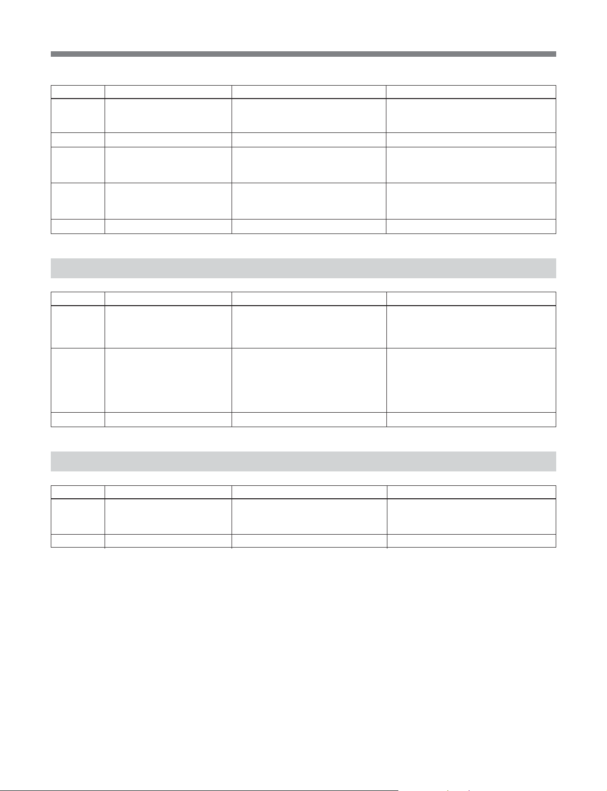
Error code Message Cause Steps to take
E131 R-CUEUP TIME OUT • VTR setting error
• VTR error
• 9-pin communications error
E112
E113 P-SERVO LOCK ERROR • VTR setting error
E133 R-SERVO LOCK ERROR • VTR setting error
E114 OTHER EDIT ERROR Undefined error —
ILLEGAL SOURCE TAPE
Operation error
• VTR error
• Cassette recording/playback error
• VTR error
• Cassette recording/playback error
Check the recorder edit point timecode.
—
• Check that the cassette is OK.
• Check that the VTR is OK.
• Check that the cassette is OK.
• Check that the VTR is OK.
Data Errors
Error code Message Cause Steps to take
E201
E202 CC LAG-SPEC OVR The delay in closed caption data
E299 OTHER DATA ERROR Undefined error —
CC DATA OVRFLW
At the end of the edit, there was
unwritten closed caption data
(delay with respect to the original
picture) exceeded specifications
(under 20 frames).
Set menu item CC WRITE to OFF or
select a frame containing no caption data
for the player Out point, and redo the
edit.
There is too much closed caption data to
perform compression editing at the
selected rate.
Set menu item CC WRITE to OFF or
change the compression rate, and redo
the edit.
Other Errors
Error code Message Cause Steps to take
E901 ILLEGAL FIELD ADRS Frame data address number for SDI
input and output are same or illegal
number by system timing failure.
E999 UNKNOWN ERROR Undefined error —
Check the system connections, VTR
state and REF signal.
17
Page 21

Specifications
General
Power requirements
100 V to 240 V AC, 50/60Hz
Power consumption
45 W
Operating temperature
5°C to 40°C (41°F to 104°F)
Storage temperature
–20°C to +60°C (–4°F to +140°F)
Humidity 20% to 90%
Mass 8 Kg (17 lb 10 oz)
Dimensions 424 × 100 × 533 mm (16
21 inches)
Input connectors
SDI INPUT BNC (1)
Serial digital (270 Mbits/sec)
SMPTE259M/ITU-R BT.656
REF.VIDEO INPUT
BNC (2, loop-through)
Black burst or composite sync
0.3 Vp-p, 75 Ω, sync minus
3
/4 × 4 ×
Accessories supplied
Rack mount screws +B4 × 8 (10)
Program Play Box Control Software and Operation
Manual (CD-ROM) (1)
Installation Manual (1)
Operation Guide (1)
Design and specifications are subject to change
without notice.
Output connectors
SDI OUTPUT BNC (2)
Serial digital (270 Mbits/sec)
SMPTE259M/ITU-R BT.656
TIME CODE OUT
XLR, 3-pin, male (1)
2.2 Vp-p, low impedance, balanced
Remote connectors
REMOTE IN (RS-232C)
D-sub 9-pin, male
RS-232C D-sub 9-pin, male
PLAYER REMOTE
D-sub 9-pin, female, RS-422A
RECORDER REMOTE
D-sub 9-pin, female, RS-422A
18
Page 22

The material contained in this manual consists of
information that is the property of Sony Corporation and is
intended solely for use by the purchasers of the equipment
described in this manual.
Sony Corporation expressly prohibits the duplication of any
portion of this manual or the use thereof for any purpose
other than the operation or maintenance of the equipment
described in this manual without the express written
permission of Sony Corporation.
Le matériel contenu dans ce manuel consiste en
informations qui sont la propriété de Sony Corporation et
sont destinées exclusivement à l’usage des acquéreurs de
l’équipement décrit dans ce manuel.
Sony Corporation interdit formellement la copie de quelque
partie que ce soit de ce manuel ou son emploi pour tout
autre but que des opérations ou entretiens de l’équipement
à moins d’une permission écrite de Sony Corporation.
Page 23

RM-PP1
(UC)
3-704-636-02(1)
Sony Corporation
B & P Company
2002
 Loading...