

Page 1
3-862-813-17(1)
MO Disk Unit RMO-S551
User’s Guide
Mode d’emploi
Bedienungsanleitung
Guía del usuario
Istruzioni per l’uso
Page 2
Safety Regulations
Owner’s Record
The model and serial numbers are located on the
bottom of the unit. Record the serial number in
the space provided below.
Refer to them whenever you call upon your Sony
dealer regarding this product.
Model No. RMO-S551
Serial No._________________________
Information
For the customer in the U.S.A.
You are cautioned that any changes or
modifications not expressly approved in this
manual could void your authority to operate this
equipment.
This equipment has been tested and found to
comply with the limits for a Class B digital
device, pursuant to Part 15 of the FCC Rules.
These limits are designed to provide reasonable
protection against harmful interference in a
residential installation. This equipment generates,
uses, and can radiate radio frequency energy and,
if not installed and used in accordance with the
instructions, may cause harmful interference to
radio communications. However, there is no
guarantee that interference will not occur in a
particular installation. If this equipment does
cause harmful interference to radio or television
reception, which can be determined by turning
the equipment off and on, the user is encouraged
to try to correct the interference by one or more
of the following measures:
–Reorient or relocate the receiving antenna.
–Increase the separation between the equipment
and receiver.
–Connect the equipment into an outlet on a
circuit different from that to which the receiver
is connected.
–Consult the dealer or an experienced radio/TV
technician for help.
WARNING
To reduce the risk of fire or
electric shock, do not expose this
apparatus to rain or moisture.
To avoid electrical shock, do not
open the cabinet. Refer servicing
to qualified personnel only.
CAUTION
As the laser beam used in the RMO-S551 is
harmful to the eyes, do not attempt to
disassemble the unit.
Refer servicing to qualified personnel only.
The use of controls or adjustments or
performance of procedures other than those
specified herein may result in hazardous
radiation exposure.
This label is affixed inside the unit.
CAUTION
ATTENTION
VORSICHT
ADVARSEL
ADVARSEL
VARNING
VARO!
This MO disk unit is classified as a CLASS 1
LASER PRODUCT.
The CLASS 1 LASER PRODUCT
label is located on the bottom exterior.
CLASS 1
LASER PRODUCT
LASER KLASSE 1
PRODUKT
LUOKAN 1 LASERLAITE
KLASS 1 LASER APPARAT
CLASS 3B LASER RADIATION WHEN OPEN.
AVOID DIRECT EXPOSURE TO THE BEAM.
RADIATIONS LASER DE CLASSE 3B EN CAS D'OUVERTURE.
EVITER TOUTE EXPOSITION DIRECTE AU FAISCEAU.
KLASSE 3B LASERSTRAHLUNG WENN GEÖFFNET.
DIREKTEN KONTAKT MIT DEM STRAHL VERMEIDEN.
LASERSTRÅLING AF KLASSE 3B VED ÅBNING.
UNDGÅ DIREKTE UDSÆTTELSE FOR STRÅLING.
LASERSTRÅLING I KLASSE 3B NÅR DEKSEL ÅPNES.
UNNGÅ DIREKTE EKSPONERING FOR STRÅLEN.
KLASS 3B LASERSTRÅLNING NÄR DENNA DEL ÄR ÖPPNAD.
UNDVIK ATT DIREKT EXPONERA DIG FÖR STRÅLNINGEN.
AVATTUNA LUOKAN 3B LASERSÄTEILYÄ.
VÄLTÄ SUORAA ALTISTUMISTA SÄTEELLE.
This device requires shielded interface cables to
comply with FCC emission limits.
2
Page 3
NOTICE
Use the power cord set approved by the
appropriate testing organization for the
specific countries where this unit is to be used.
CAUTION
The mains plug on this equipment must be
used to disconnect mains power.
Please ensure that the socket outlet is installed
near the equipment and shall be easily
accessible.
Table of Contents
Using this Guide........................................ 4
English
Chapter 1 Introduction
Overview .................................................... 5
Features....................................................... 5
Compatible Disks ....................................... 6
System Configuration ................................. 6
Location and Function of Parts ............... 7
Disposal of Old Electrical & Electronic
Equipment (Applicable in the European
Union and other European countries with
separate collection systems)
This symbol on the product or on its
packaging indicates that this product
shall not be treated as household
waste. Instead it shall be handed over
to the applicable collection point for
the recycling of electrical and
electronic equipment. By ensuring this product is
disposed of correctly, you will help prevent
potential negative consequences for the
environment and human health, which could
otherwise be caused by inappropriate waste
handling of this product. The recycling of
materials will help to conserve natural resources.
For more detailed information about recycling of
this product, please contact your local Civic
Office, your household waste disposal service or
the shop where you purchased the product.
According to the EU Directives related to
product safety, EMC and R&TTE the
manufacturer of this product is Sony
Corporation, 6-7-35 Kitashinagawa
Shinagawa-ku Tokyo, 141-0001 Japan.
The Authorised Representative is Sony
Deutschland GmbH, Hedelfinger Strasse
61,70327 Stuttgart, Germany.
For any service or guarantee matters please
refer to the addresses given in separate service
or guarantee documents.
Chapter 2 Getting Started
Component and Accessory Check List .. 8
Connecting the Disk Unit ......................... 9
Setting the SCSI ID.................................... 9
Setting the Disk Unit’s Functions .......... 10
Chapter 3 Using the Disk Unit
Inserting a Disk Cartridge ...................... 11
Ejecting a Disk Cartridge........................ 12
Chapter 4 Precautions
On the Disk Unit ...................................... 13
Safety Considerations ............................... 13
Damage Prevention .................................. 13
Other Points Requiring Attention ............. 14
On the Disk Cartridges ........................... 14
Protecting Your Data ................................ 15
Cleaning ................................................... 15
Cleaning a Disk ........................................ 15
Appendix
Specifications .......................................... 16
Disk Unit .................................................. 16
Optional Accessories ................................ 17
3
Page 4

Using this Guide
This guide covers the use and operation of the
RMO-S551 Magneto-Optical Disk Unit (called
the “disk unit” thereafter). Do not attempt to use
the disk unit without first carefully reading this
guide. When finished, keep it handy for future
reference.
The guide is divided into the following sections.
Chapter 1 Introduction
This chapter contains a general overview of the
RMO-S551 disk unit, touching upon its features,
system configuration, and the location and
function of its parts.
Chapter 2 Getting Started
This chapter explains how to connect the disk
unit to the host computer and other SCSI
peripheral devices. It also explains how to set the
disk unit’s functions and the SCSI ID. Refer to
this chapter when setting up the disk unit.
Chapter 3 Using the Disk Unit
In this chapter, you learn how to turn on the disk
unit, and how to insert and eject a disk cartridge.
Refer to this chapter when you are ready to
actually begin using the disk unit.
Notes
• The manufacturer disclaims all responsibility
for any losses incurred through malfunction or
use of this product.
• The manufacturer does not warrant the security
of data stored using this product. To guard
accidental data loss, frequent backup of
important data is highly recommended.
• Reproduction of the contents of this manual, in
whole or in part, is prohibited.
•Macintosh is a registered trademark of Apple
Computer, Inc.
•Microsoft and Windows are registered
trademarks of Microsoft Corporation.
Chapter 4 Precautions
This chapter contains precautions regarding the
use and operation of the disk unit and magnetooptical disk cartridges.
It also discusses cleaning of disks.
Be sure to refer to this chapter before using the
disk unit.
Appendix
The Appendix contains an explanation of the disk
unit’s main specifications.
4
Page 5

Chapter 1 Introduction
Overview
Features
The RMO-S551 Magneto-Optical Disk Unit has
the following features:
•Magneto-optical technology enables repeated
writing and erasing of data on the disk.
• The disk unit automatically senses the type of
disk being inserted, enabling the free use of
both 650 Mbytes (594 Mbytes), 1.3 Gbytes (1.2
Gbytes), 2.6 Gbytes (2.3 Gbytes), and 5.2
Gbytes (4.8 Gbytes, 4.1 Gbytes) disks
indifferently.
•A maximum of 5.2 Gbytes (2,048 bytes/sector),
4.8 Gbytes (1,024 bytes/sector), or 4.1 Gbytes
(512 bytes/sector) of data can be written on the
two sides of a 5.25-inch magneto-optical disk.
This is equivalent to about 2900–3700 times the
capacity of a conventional 3.5-inch floppy disk
(2HD).
• Any disk conforming to the internationally
accepted CCS (continuous/composite servo) or
CCW (continuous composite write-once) format
can be used in this disk unit.
• This disk unit employs SCSI-2 (Small
Computer System Interface-2).
• The 3,300 min
spindle motor enables data transfer rates of
2.48 – 5.07 Mbytes/s (2,048 bytes/sector),
2.31 – 4.79 Mbytes/s (1,024 bytes/sector), or
1.97 – 4.06 Mbytes/s (512 bytes/sector).
•With disk capacities under 2.6 Gbytes (2.3
Gbytes), the spindle motor rotates at 3600 min
(rpm).
• The low-profile, light-weight optical pick-up
yields average seek times of 25ms.
• Use of a highly reliable error correction code
(ECC) system keeps the error rate as low as
-12
10
.
• Optimum operation environment is provided
through use of a large, 4MB buffer and
optimized cache control algorithm. (Write cache
can be enabled or disabled. For details, see
“Setting the Disk Unit’s Functions” on page
10.)
-1
(3,300 rpm) high-speed
-1
Chapter 1 Introduction 5
Page 6

Compatible Disks
The RMO-S551 can use the following Sony 5.25-inch MO Disks:
Standard Sector format Type* Capacity Sony equivalent
ISO/IEC 15286 2048 bytes/sector R/W About 5.2 G bytes EDM-5200B
ISO/IEC 15286 1024 bytes/sector R/W About 4.8 G bytes EDM-4800B
ISO/IEC 15286 512 bytes/sector R/W About 4.1 G bytes EDM-4100B
ISO/IEC 14517 1024 bytes/sector R/W About 2.6 G bytes EDM-2600B
ISO/IEC 14517 512 bytes/sector R/W About 2.3 G bytes EDM-2300B
ISO/IEC 13549 1024 bytes/sector R About 1.3 G bytes EDM-1300B
ISO/IEC 13549 512 bytes/sector R About 1.2 G bytes EDM-1200B
ISO/IEC 10089 1024 bytes/sector R About 650 M bytes EDM-650B
ISO/IEC 10089 512 bytes/sector R About 600 M bytes EDM-600B
ISO/IEC 15286 2048 bytes/sector WO About 5.2 G bytes CWO-5200B
ISO/IEC 15286 1024 bytes/sector WO About 4.8 G bytes CWO-4800B
ISO/IEC 15286 512 bytes/sector WO About 4.1 G bytes CWO-4100B
ISO/IEC 14517 1024 bytes/sector WO About 2.6 G bytes CWO-2600B
ISO/IEC 14517 512 bytes/sector WO About 2.3 G bytes CWO-2300B
ISO/IEC 13549 1024 bytes/sector R About 1.3 G bytes CWO-1300B
ISO/IEC 13549 512 bytes/sector R About 1.2 G bytes CWO-1200B
ISO/IEC 11560 1024 bytes/sector R About 650 M bytes CWO-650B
ISO/IEC 11560 512 bytes/sector R About 600 M bytes CWO-600B
*R/W:Rewritable, R/W:Rewritable(MO), WO:Write Once, R:Read Only
System Configuration
The disk unit should be used with a host
A maximum of seven peripheral devices can be
linked in a daisy chain on the SCSI bus, and
controlled with SCSI-2 commands.
computer equipped with SCSI.
Host computer
SCSI cable
RMO-S551 disk unit SCSI peripheral devices
6 Chapter 1 Introduction
Page 7
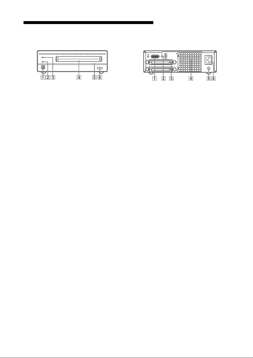
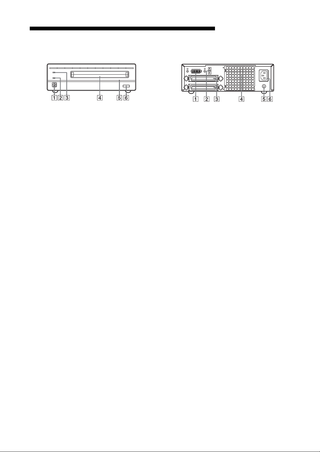
Location and Function of Parts
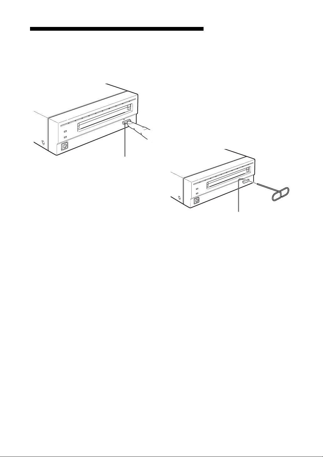
Front Panel
BUSY
POWER
EJECT
1 POWER switch
Push the button to turn the power on and off.
The power is on when the button is in the
depressed position, and off when fully
protruding.
2 POWER indicator
The green lamp lights up when the power is
turned on.
3 BUSY indicator
As this disk is inserted and the drive becomes
ready for read/write operation, the BUSY
indicator turns green. The orange lamp lights
up when the disk unit is accessing or writing
data. This lamp flashes on and off at about 2second intervals when the unit overheats,
regardless of whether or not a disk is being
accessed.
4 Disk insertion slot
Insert the disk cartridge into this slot. Refer
to the section “Inserting a Disk Cartridge” on
page 11 for more information.
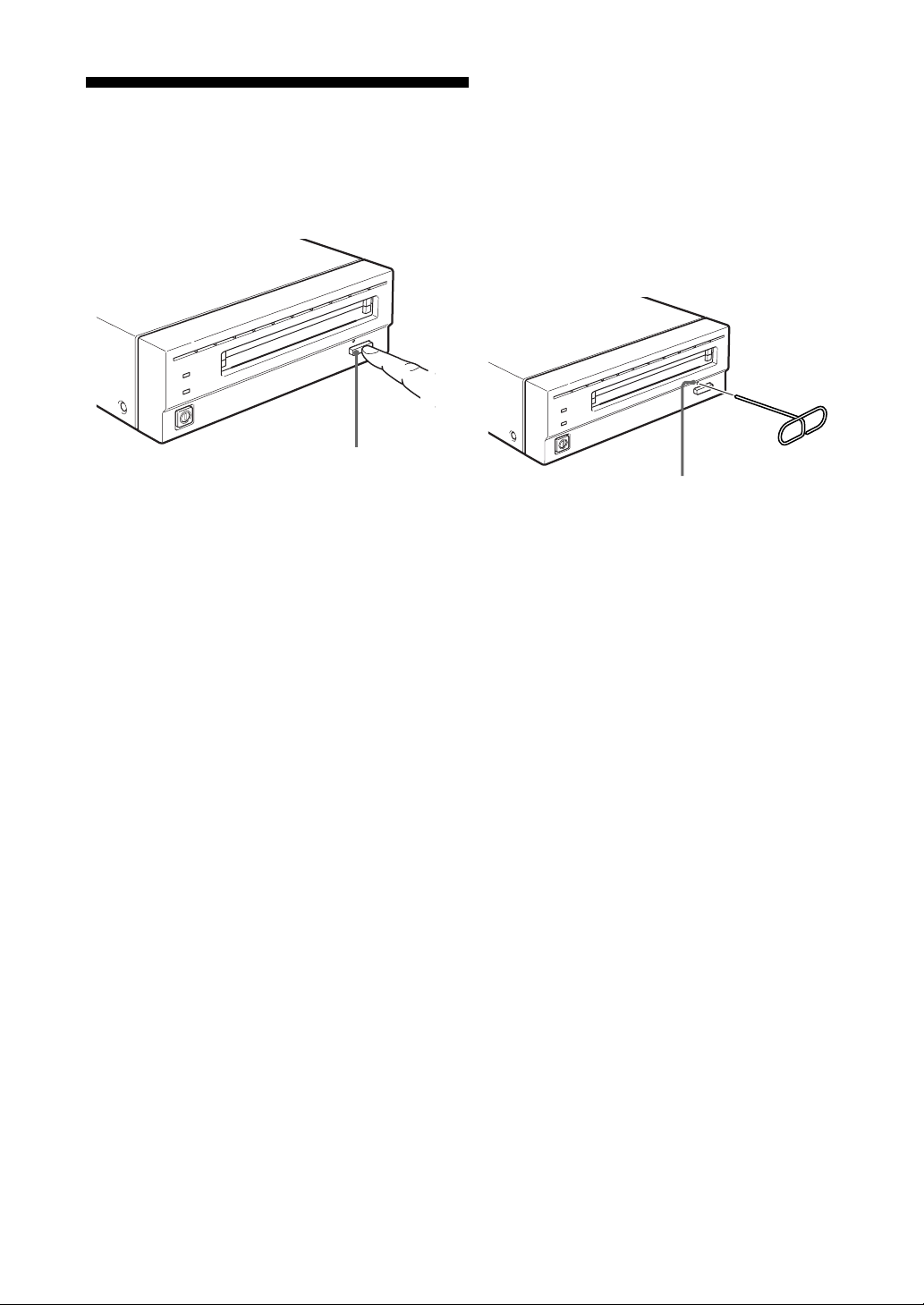
5 Emergency eject hole
If the disk cartridge cannot be ejected using
the EJECT button 6, turn off the power and
insert the supplied emergency eject tool into
this hole to trip the emergency eject
mechanism. Refer to the section “What to do
if the disk does not eject” on page 12 for
further details.
6 EJECT button
Press this button to eject the disk cartridge
from the disk unit. The EJECT button is
disabled with the function switch or software
settings prohibit ejection. When the write
cache is enabled, it may take a few moments
(up to 45 seconds) for the disk to eject
because data in the cache must first be
written to the disk.
Rear Panel
A1BCDEFGH
0
SCSI ID
SCSI CONNECTOR
AC IN
F.GND
1 Function switches
Use this switches to set the disk unit’s
functions in accordance with the host
computer and software being used. Refer to
the section“Setting the Disk Unit’s
Functions” on page 10 for more information.
2 SCSI ID switch
Use these switches to set the SCSI ID. Push
the “–” button to lower the ID number; push
the “+” button to raise the ID number. Refer
to the section“Setting the SCSI ID”on page 9
for more information.
3 SCSI connectors
Plug SCSI cables (sold separately) linking
the host computer and other SCSI peripherals
into these connectors.
Note
If the disk unit is the last device on the SCSI
chain, set function switch F to “1” to turn on
the internal terminator. When it is not the last
device, make sure that the terminator is off
(switch F is set to “0”).
4 Air duct
The air for cooling the disk unit flows
through this duct, so be careful not to block
its surface or impede the outflow.
5 F.GND (frame ground) terminal
Connect the ground terminals of other
devices to the disk unit’s frame ground.
6 AC IN (AC power) connector
Connect the supplied AC power cord to this
connector.
Chapter 1 Introduction 7
Page 8
Chapter 2 Getting Started
Before setting up your RMO-S551 MagnetoOptical Disk Unit, check to see that you have all
the required components and accessories. Then,
connect the disk unit to the host computer and
any other SCSI peripherals you may be using.
After checking to see that all the connections
have been properly made, set the SCSI ID using
the SCSI ID switch and the disk unit’s functions
using the function switches.
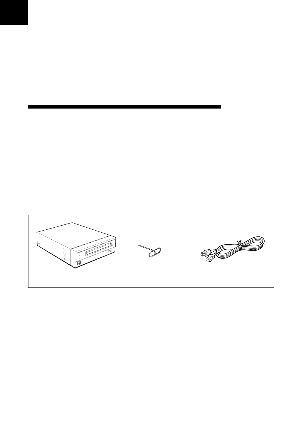
Component and Accessory Check List
Upon opening the carton, check to see that you
have all of the components and accessories listed
below. Contact your dealer immediately if you
find any missing or damaged items.
•RMO-S551 Magneto-Optical Disk Unit
• AC power cord
• Emergency eject tool
• User’s Guide
• Guide to Safe Use (Safety Precautions)
•1 Blank MO disk (EDM-5200B)
Note
Please refer to the installation manual included in
the device driver’s package for instructions when
using this device with a Macintosh® computer or
a computer running under Windows® system. For
questions concerning the device drivers, please
contact the device driver manufacturer as
indicated in the device driver package.
RMO-S551 Emergency eject tool AC Power cord
Magneto-Optical Disk Unit
8 Chapter 2 Getting Started
Page 9
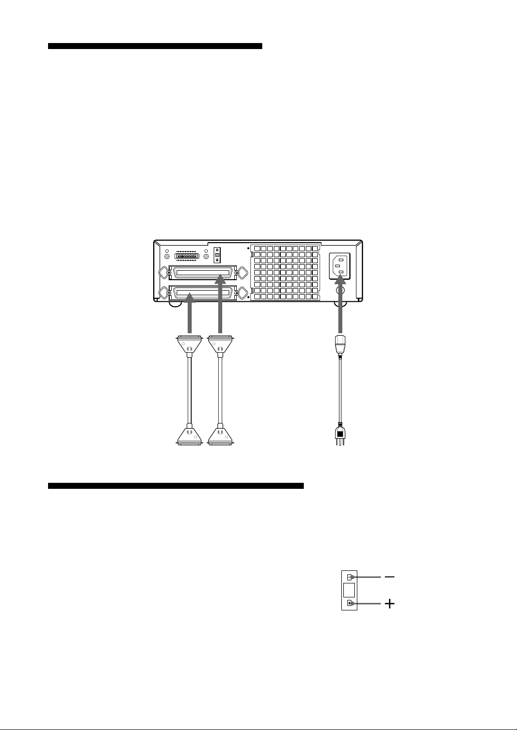
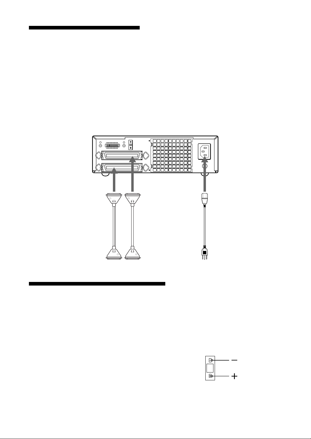
Connecting the Disk Unit
You can hook up a maximum of seven SCSI
peripheral devices to a single host computer
through its SCSI bus.
Use the following Sony SCSI cable to connect
the disk unit.
Notes
• Before connecting the disk unit, be sure to turn
off the disk unit and all other devices on the
SCSI chain.
RMO-S551 Magneto-Optical Disk Unit
A1BCDEFGH
0
SCSI CONNECTOR
SCSI ID
to SCSI connector
SCSI cableSCSI cable
• If the disk unit is the last device on the SCSI
chain, set the function switch F on the rear
panel to “1” to turn on the internal terminator.
When it is not the last device, make sure that the
terminator is off (function switch F is set to
“0”).
• The total length of the SCSI cables connected to
a SCSI chain must not exceed six meters (19
feet 8 1/4 inches).
AC IN
F.GND
to AC IN
connector
AC power cord
(supplied)
to another
SCSI device
to the host computer or
another SCSI device
Setting the SCSI ID
The factory default setting for the SCSI ID is “0.”
If necessary, this ID number can be changed
using the SCSI ID switch on the rear panel. Be
sure to turn off the power before making any
changes.
Pushing the “+” button raises the ID number;
pushing the “–” button lowers the ID number.
Notes
• The disk unit will not operate properly unless
the SCSI ID has been set correctly.
to an AC outlet
•Make sure to select a SCSI ID that has not been
assigned to another SCSI device.
0
Chapter 2 Getting Started 9
Page 10
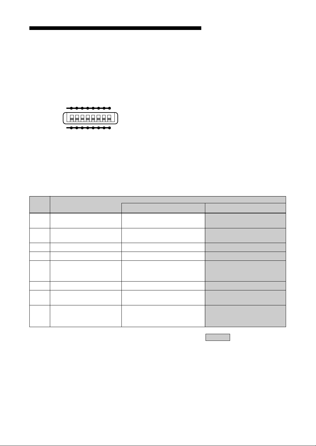
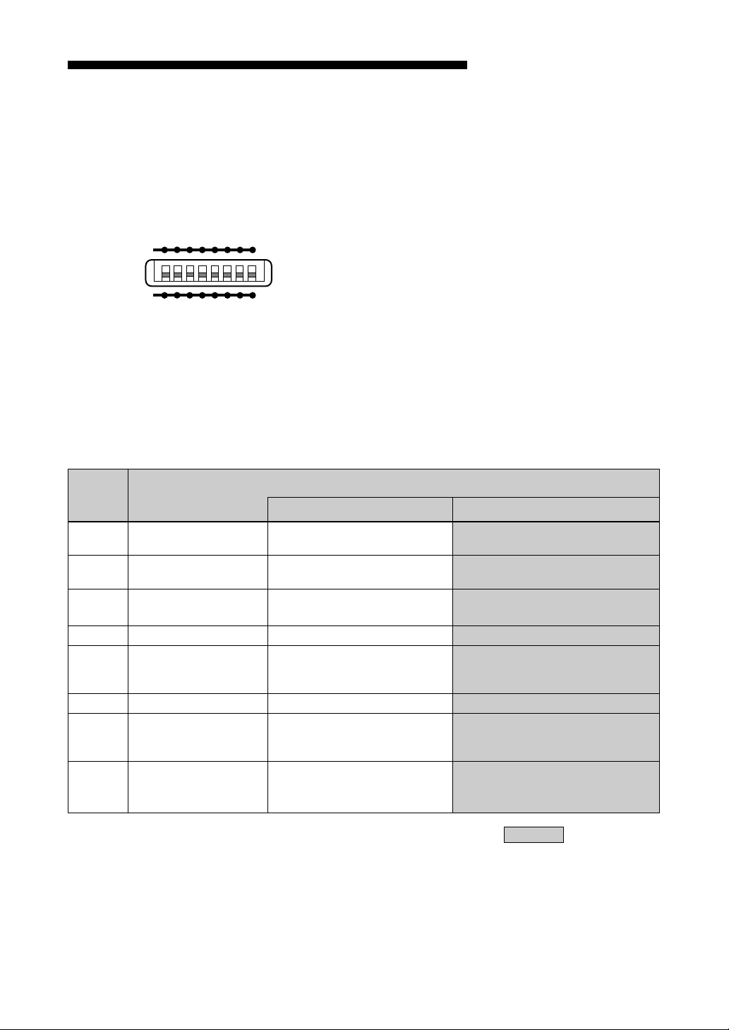
Setting the Disk Unit’s Functions
Use function switches (A – H) on the rear panel
to select the disk unit’s functions in accordance
with the host computer and software you are
using. Be sure to turn off the power before setting
the switches.
This disk unit is equipped with a write cache.
When the write cache is enabled, never turn off
the disk unit power without making sure that all
data has been written to the disk from cache
memory. Data will be lost if you turn off the
power before all data in cache memory has been
A1BCDEFGH
written to the disk.
Before powering off the disk unit, be sure to eject
the disk. Ejecting the disk writes data from cache
0
memory to the disk.
Note
Even though the drive will flush data periodically
to the disk, data may be lost in the case of a
power failure.
Function Switch Settings
Switch Function
A Parity check SCSI parity check is disabled. SCSI parity check is
B Device type Peripheral device type 00H Peripheral device type 07H
(Direct Access Device) (Optical Memory Device)
C Write cache control Disable write cache. Enable write cache.
D Fast SCSI control Fast SCSI compatible Not Fast SCSI compatible
E Force verify All write operations are verfied. All write operations are
(with a verify pass) (without a verify pass)
F Terminator The internal terminator is on. The internal terminator is off.
G Auto spin up Inserting a disk does not causes Inserting a disk causes
the spindle motor to rotate. the spindle motor to rotate.
H Manual eject Disk catridge cannot be ejected Disk cartridge can be
by pressing the EJECT button. ejected by pressing the
10
enabled.
normal operations.
EJECT button
10 Chapter 2 Getting Started
: Factory setting
Page 11
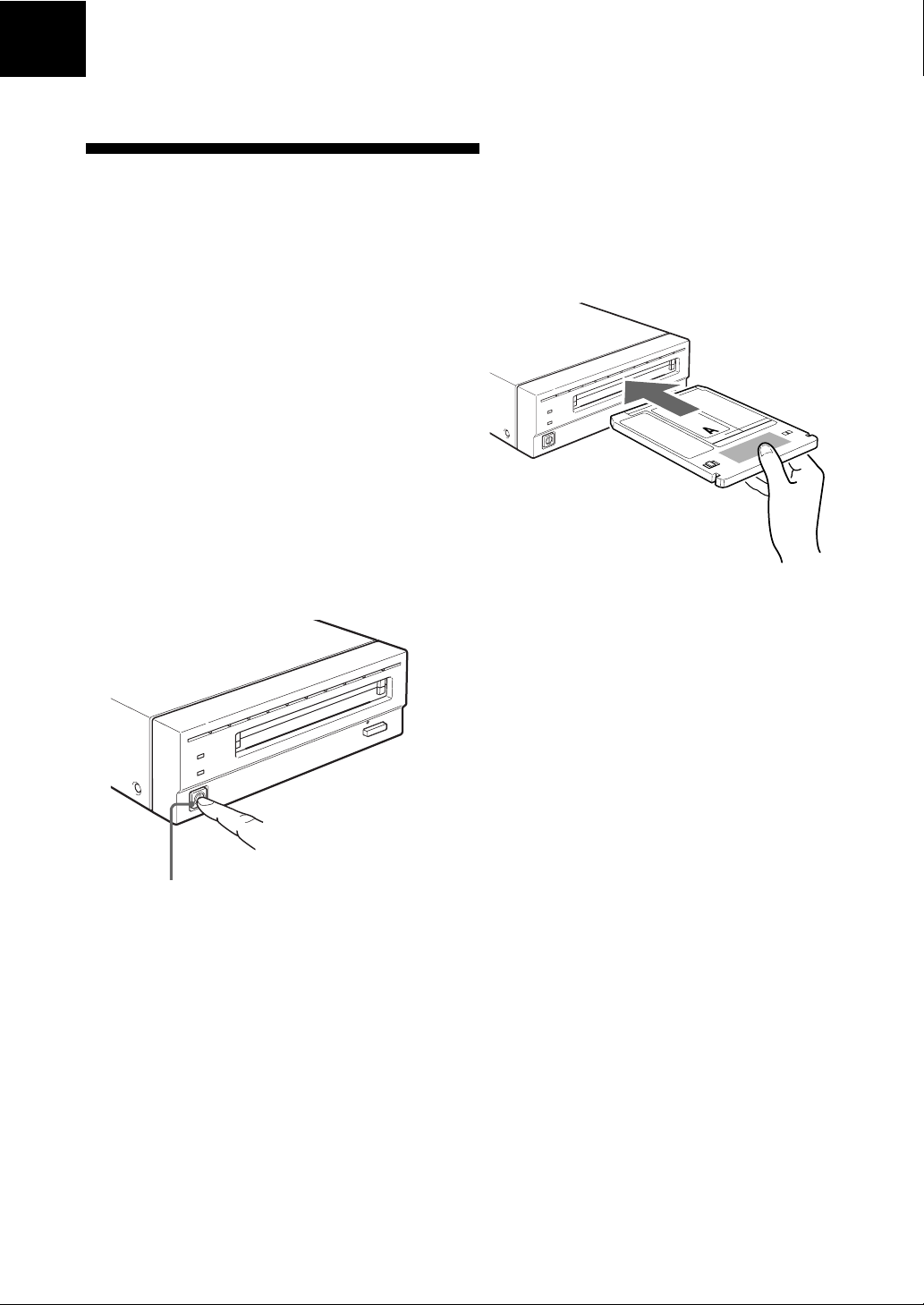
Chapter 3 Using the Disk Unit
Inserting a Disk Cartridge
Use the following Sony 5.25-inch MO disks in
your RMO-S551 disk unit.
• EDM-5200B (2,048 bytes/sector, 5.2 Gbytes)
• EDM-4800B (1,024 bytes/sector, 4.8 Gbytes)
• EDM-4100B (512 bytes/sector, 4.1 Gbytes)
• EDM-2600B (1,024 bytes/sector, 2.6 Gbytes)
• EDM-2300B (512 bytes/sector, 2.3 Gbytes)
•CWO-5200B (2,048 bytes/sector, 5.2 Gbytes )
•CWO-4800B (1,024 bytes/sector, 4.8 Gbytes)
•CWO-4100B (512 bytes/sector, 4.1 Gbytes)
•CWO-2600B (1,024 bytes/sector, 2.6 Gbytes )
•CWO-2300B (512 bytes/sector, 2.3 Gbytes)
1 Press the POWER switch located on the left
side of the front panel.
This turns on the disk unit and causes the
POWER indicator to light up.
3 Insert a disk cartridge with the side you want
to use facing upwards.
To use Side A, insert the
disk with “A” facing
upward.
4 Access or write data on the disk using
software commands on the host computer.
The BUSY indicator lights up while the unit
is accessing the disk.
■ What to do if the disk unit stops
operating
Press the POWER switch
2 Start up the host computer. Refer to the
manual supplied with the host computer for
the start up procedure.
When the temperature in the disk unit exceeds
the preset level, the BUSY indicator starts
flashing on and off at about 2-seconds intervals,
regardless of whether or not a disk is being
accessed, and the disk unit stops operating.
If this happens, you should improve the
ventilation of a setting area.
If the disk unit still refuses to operate, unplug the
unit and contact your dealer.
Chapter 3 Using the Disk Unit 11
Page 12
Ejecting a Disk Cartridge
Eject the disk cartridge either by using software
commands or by pressing the EJECT button.
EJECT button
Note
Do not attempt to eject a disk cartridge while the
BUSY indicator is lit orange (except when it is
flashing at about 2-second intervals due to
overheating). Ejecting the disk while it is being
accessed may cause data write errors or may
result in loss of data.
Also, it may take a few moments (up to 45
seconds) for the disk to eject when the write
cache is enabled, because data in the cache must
first be written to the disk.
1 Turn off the disk unit if the power is still on.
2 Insert the emergency eject tool (or a paper
clip) straight into the emergency eject hole to
trip the manual ejection mechanism.
Emergency
eject Tool
Insert into the
emergency eject hole.
This should cause the disk cartridge to eject.
Caution
The tip of the emergency eject tool is sharp.
When handling the tool, please be careful to
avoid injury.
■ What to do if the disk does not
eject
The disk cartridge may not come out, even when
you press the EJECT button or use a software
command, under the following conditions:
• The eject function has been disabled using the
function switch or a software command;
• The host computer is not functioning properly;
• The disk unit has been turned off (due to a
power failure, etc.); or
• Something is wrong with your disk unit itself.
When you cannot eject the disk cartridge using
the EJECT button or software commands,
remove it as follows.
12 Chapter 3 Using the Disk Unit
Page 13

Chapter 4 Precautions
On the Disk Unit
Safety Considerations
■ Power supply
• Be sure to use 100 - 240V AC.
• Do not share the AC outlet with any other
power-consuming equipment such as copying
machines or shredders.
■ AC power cord
• Be careful not to place or drop heavy object on
the power cord, or subject it to anything that
may damage it.
•When unplugging the cord from an AC outlet,
be sure to grasp the plug itself. Pulling on the
cord may cause damage to the internal wiring.
• Unplug the unit when not using it for long
period of time.
■ Handling the emergency eject tool
The tip of the emergency eject tool is sharp.
When handling the tool, please be careful to
avoid injury. Do not use the tool for any purpose
other than ejecting disks.
Damage Prevention
■ Do not subject the disk unit to
shock or vibration
Dropping the unit or subjecting it to strong
impact may damage the disk unit.
■ Setting position
■ Location requirements
Careful consideration should be given to the
following in selecting a site to install or store
your disk unit.
Avoid the following conditions:
• High humidity
• High temperatures
• Direct sunlight
• Dust
• Strong vibration
•Wide temperature fluctuations
■ Ventilation
Care should be exercised to prevent the internal
mechanisms of the disk unit from overheating.
Be careful not to clog or block the vent, or place
the unit in an area with poor ventilation. The disk
unit may stop operating altogether if the internal
temperature becomes too high.
■ Condensation
Avoid subjecting the disk unit to extremes in
temperature. If, for example, the disk unit is
moved suddenly from a very cold location to a
warm one, moisture from condensation may form
within the unit due to the quick rise in ambient
temperature. If a sudden change in the
temperature cannot be avoided, wait for an hour
or more before using the disk unit. Inserting a
disk cartridge into the mechanism when moisture
is present may cause damage to both the disk and
the disk unit. Remove the disk cartridge
immediately if you suspect any condensation
problems. The moisture should evaporate quickly
if the disk unit is left on without a disk inserted.
The disk unit is designed to be used in the
horizontal position. Do not position it at an angle.
Chapter 4 Precautions 13
Page 14

■ Moving the disk unit
Be sure to remove the disk cartridge when the
disk unit is not being used. Also never move or
transport the unit with the disk cartridge still
inserted.
While in operation, the disk rotates at a high
speed. Moving the disk unit at such a time may
disturb the spinning disk and cause it to be
damaged. Always remove the disk cartridge
before moving your disk unit.
Other Points Requiring Attention
■ Electrical noise
The high-frequency signal generated by the disk
unit may cause interference or static on other
electrical appliances such as radios, televisions
and audio tuners. If this should occur, move the
disk unit a little farther away from the affected
appliance.
■ If problems occur
If any problems occur, turn off the power and
unplug the disk unit, contact your dealer.
On the Disk Cartridges
• Do not drop the disk cartridge or subject it to
any violent shocks or vibration.
• Do not disassemble the disk cartridge. It is a
precision component and has been carefully
adjusted at the factory prior to shipment.
• Do not open the disk cartridge’s shutter
manually or touch the disk inside. The shutter is
designed to open automatically when the
cartridge is inserted into the disk unit.
• Do not use the cartridge under ambient
conditions of high humidity or wide
temperature fluctuations. Moisture from
condensation may make it impossible to read or
write data.
• Avoid inserting and ejecting the disk cartridge
more than is necessary.
• Always eject and remove the disk cartridge
from the disk unit after using it.
■ Maintenance
Clean the cabinet with a dry soft cloth, or with a
soft cloth lightly moistened with a mild detergent
solution. Do not use any type of solvent, such as
alcohol or benzine, which may damage the finish.
■ Storing disk cartridges
• Store the disk cartridges in their cases.
• Do not leave the cartridges exposed to direct
sunlight or excessive heat, like on the dashboard
or in the glove compartment of an automobile.
Do not store the disk cartridges under the
following conditions.
– Excessive dust and debris
– Exposure to direct sunlight
– Near a heat source
– High humidity
14 Chapter 4 Precautions
Page 15
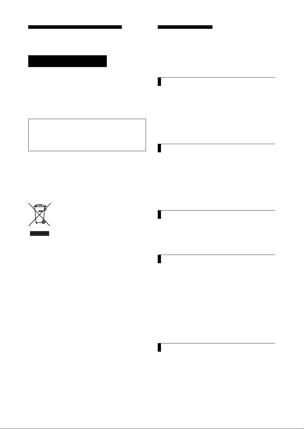
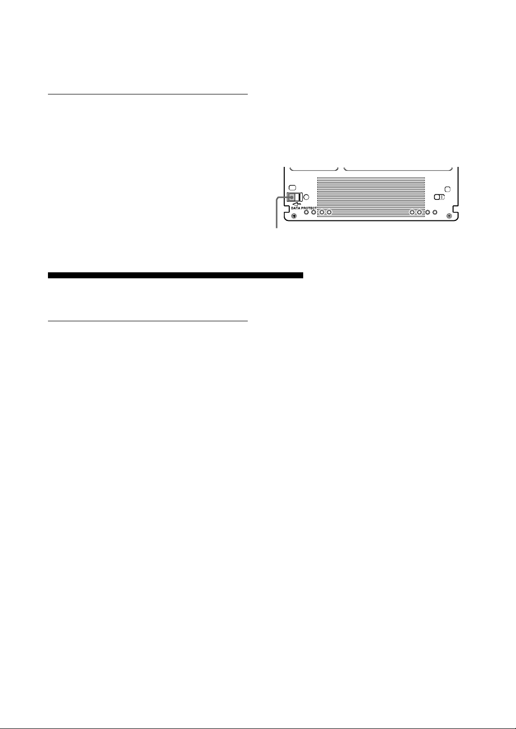
Protecting Your Data
The magneto-optical disk cartridges are equipped
with a DATA PROTECT switch (red tab) to
prevent accidental erasure of data on the disk or
inadvertent writing of unwanted data. Slide this
switch in the direction of the arrow as illustrated
below to enable the write protect function.
You can still read the data contained on the disk,
but will not be allowed to write on or erase the
disk. Return the switch to its original position to
disable the write protect.
Cleaning
Make it a practice to leave the write protection
enabled when you do not foresee the need to
write on the disk.
DATA PROTECT
switch
Cleaning a Disk
Dust and stains may accumulate on MO disks
when they are used for a long period of time. To
avoid resultant data read/write errors, use an
optional disk cleaner. To maintain the high
performance and prolong the useful life of your
MO disk, cleaning at least once every three
months is recommended.
■ Disk cleaning accessories
Use the following Sony disk cleaning kit or disk
cleaner (sold separately).
•MOA-D51 Disk Cleaning Kit
Do not use any other type of disk cleaner as it
may cause data read/write errors due to the
differences in disk surface characteristics. For
cleaning instructions, refer to the manual
supplied with each cleaning accessory
Attention
In the disk unit, preventive measures are taken to
guard against dust. It is unnecessary to clean the
optical lens of your disk unit. Using a lens
cleaning cartridge may damage the disk unit.
Chapter 4 Precautions 15
Page 16

Appendix
Specifications
Disk Unit
■ Performance
Capacity
Per disk
5.2 Gbytes (ZCAV 2,048 bytes/sector)
4.8 Gbytes (ZCAV 1,024 bytes/sector)
4.1 Gbytes (ZCAV 512 bytes/sector)
2.6 Gbytes (ZCAV 1,024 bytes/sector)
2.3 Gbytes (ZCAV 512 bytes/sector)
Rotation speed
3,300 min–1 (3,300 rpm)
3,600 min–1 (3,600 rpm)
Seek times (average)
25 ms (typical)
User data transfer rate
Continuous transfer rate
2.48 – 5.07 Mbytes/s
(2,048 bytes/sector)
2.31 – 4.79 Mbytes/s
(1,024 bytes/sector)
1.97 – 4.06 Mbytes/s
(512 bytes/sector)
Burst transfer rate
10 Mbytes/s (using Fast SCSI)
Host interface
SCSI-2 (Small Computer System Interface-2)
ANSI X3.131–1994
■ Laser
Type
Semiconductor AlGaInP laser
Wavelength
685 nm ± 10 nm
Maximum output
30 mW
■ Power supply and others
Power supply
100 – 240 V AC ±10%, 50/60 Hz ±5%
Current drain
0.60 – 0.35 A max
Maximum external dimensions (excluding
protruding parts and air duct)
211 × 70 × 293 mm (W/H/D)
(8 3/8 × 2 7/8 × 11 5/8 inches)
Weight
4.9 kg (10.9 lb.)
Accessories
AC power cord (1)
Emergency eject tool(1)
User’s Guide (1)
MO Disk (1)
Formatting Utility (1)
Design and specifications are subject to change
without notice.
■ Operating environment
Installation
Horizontal (±5°)
Temperature
Operating
5 °C to 40 °C (41 °F to 104 °F)
(gradient 10° C/h or 18 °F/h)
Non-operating
– 30 °C to 60 °C (– 22 °F to 140 °F)
Relative humidity
Operating
10 % to 85 % (no condensation)
Non-operating
10 % to 90 %
16 Appendix
Page 17

Optional Accessories
MO disks
EDM-5200B (2,048 bytes/sector, 5.2 Gbytes)
EDM-4800B (1,024 bytes/sector, 4.8 Gbytes)
EDM-4100B (512 bytes/sector, 4.1Gbytes)
EDM-2600B (1,024 bytes/sector, 2.6 Gbytes)
EDM-2300B (512 bytes/sector, 2.3 Gbytes)
Continuous composite write-once disks
CWO-5200B (2,048 bytes/sector, 5.2 Gbytes)
CWO-4800B (1,024 bytes/sector, 4.8 Gbytes)
CWO-4100B (512 bytes/sector, 4.1 Gbytes)
CWO-2600B (1,024 bytes/sector, 2.6 Gbytes)
CWO-2300B (512 bytes/sector, 2.3 Gbytes)
Disk Cleaning Kit
MOA-D51
Appendix 17
Page 18
Règles de sécurité
Sommaure
AVERTISSEMENT
Afin de réduire les risques d’incendie ou
de choc électrique, n’exposez pas cet
appareil à la pluie ni à l’humidité.
Pour éviter toute électrocution, ne pas
ouvrir le boîtier. Confier l’entretien à un
technicien qualifié uniquement.
NOTICE
Utiliser le cordon d’alimentation approuvé par
l’organisation de contrôle appropriée pour les
pays auxquels le produit est destiné.
Traitement des appareils électriques et
électroniques en fin de vie (Applicable
dans les pays de l’Union Européenne et
aux autres pays européens disposant de
systèmes de collecte sélective)
Ce symbole, apposé sur le produit ou
sur son emballage, indique que ce
produit ne doit pas être traité avec les
déchets ménagers. Il doit être remis à
un point de collecte approprié pour le
recyclage des équipements
électriques et électroniques. En s’assurant que ce
produit est bien mis au rebus de manière
appropriée, vous aiderez à prévenir les
conséquences négatives potentielles pour
l’environnement et la santé humaine. Le
recyclage des matériaux aidera à préserver les
ressources naturelles. Pour toute information
supplémentaire au sujet du recyclage de ce
produit, vous pouvez contacter votre
municipalité, votre déchetterie ou le magasin où
vous avez acheté le produit.
Comment utiliser ce Guide..................... 19
Chapitre 1 Introduction
Aperçu ...................................................... 20
Caractéristiques ........................................ 20
Disques compatibles ................................. 21
Configuration de système ......................... 21
Localisation et fonction des pièces ...... 22
Chapitre 2 Démarrage
Liste de contrôle des composants et
accessoires ...................................... 23
Connexion du lecteur ............................. 24
Réglage de l’adresse SCSI ..................... 24
Réglage des fonctions du lecteur.......... 25
Chapitre 3 Fonctionnement du lecteur
Insertion d’une cartouche disque.......... 26
Ejection d’une cartouche disque ........... 27
Chapitre 4 Précautions
A propos du lecteur ................................ 28
Sécurité ..................................................... 28
Prévention des dommages ........................ 28
Autres points à prendre en compte ........... 29
A propos des cartouches disques ........ 29
Protection des données ............................. 30
Entretien................................................... 30
Nettoyage des disques .............................. 30
18
Appendice
Spécifications .......................................... 31
Lecteur ...................................................... 31
Accessoires en option ............................... 32
Page 19

Comment utiliser ce Guide
Ce guide couvre l’emploi et le fonctionnement du
lecteur de disque magnéto-optique RMO-S551
(appelé par le suite le “lecteur”).
Ne pas essayer d’utiliser ce lecteur sans avoir
préalablement lu attentivement ce guide. La
lecture terminée, le garder à proximité pour toute
référence ultérieure.
Ce guide se divise comme suit:
Chapitre 1 Introduction
Ce chapitre contient un aperçu général du lecteur
RMO-S551, portant sur ses caractéristiques, la
configuration du système, ainsi que la
localisation et la fonction des pièces.
Chapitre 2 Démarrage
Ce chapitre explique comment raccorder ce
lecteur à l’ordinateur central et aux autres
périphériques SCSI. Il explique également le
réglage de l’adresse SCSI et des fonctions du
lecteur. Voir ce chapitre pour l’implantation du
lecteur.
Chapitre 3 Fonctionnement du lecteur
Ce chapitre indique comment mettre le lecteur
sous tension, et insérer et éjecter une cartouche
disque. Se reporter à ce chapitre quand on est prêt
à commencer à utiliser le lecteur.
Remarques:
• Le fabricant décline toute responsabilité pour
les pertes subies suite au mauvais
fonctionnement ou à l’utilisation de ce produit.
• Le fabricant ne garantit pas la sécurité des
données enregistrées en utilisant ce produit.
Pour éviter toute perte accidentelle de données,
une copie de sauvegarde fréquente est fortement
recommandée.
• La reproduction du contenu de ce mode
d’emploi, en totalité ou en partie, est interdite.
• Macintosh est une marque déposée de Apple
Computer, Inc.
• Microsoft et Windows sont des marques
déposées de Microsoft Corporation.
Français
Chapitre 4 Précautions
Ce chapitre contient les précautions concernant
l’utilisation et le fonctionnement du lecteur et des
cartouches disques magnéto-optiques.
Il couvre également le nettoyage des disques.
Se reporter à ce chapitre avant d’utiliser le
lecteur.
Appendice
L’appendice donne les spécifications principales
du lecteur.
19
Page 20

Chapitre 1 Introduction
Aperçu
Caractéristiques
Le lecteur de disque magnéto-optique RMOS551 possède les caractéristiques suivantes:
• La technologie magnéto-optique permet
l’écriture et l’effacement répétés de données sur
le disque.
• Le lecteur de disque détecte automatiquement le
type de disque en cours d’insertion, permettant
ainsi d’employer indifféremment des disques de
650 Mo (594 Mo), 1,3 Go (1,2 Go), 2,6 Go (2,3
Go) et 5,2 Go (4,8 Go, 4,1 Go).
• 5,2 Go (2.048 octets/secteur), 4,8 Go (1.024
octets/secteur), ou 4,1 Go (512 octets/secteur)
maximum de donneés peuvent être écrites sur
les deux côtés d’un disque magnéto-optique de
5,25 pouces, ce qui équivaut à environ 2900–
3700 fois la capacité d’une disquette
conventionnelle de 3,5 pouces (2HD).
• Toute disquette conforme au format
international CCS (servo continu/composite) ou
CCW (écriture unique continu/composite) peut
être utilisée dans cette unité de disquette.
• Ce lecteur de disque utilise SCSI-2 (Small
Computer System Interface-2).
• Le moteur à broche grande vitesse 3.300 min
(3.300 tr/min.) permet la transmission des
données à une vitesse de 2,48 - 5,07 Mo/s
(2.048 octets/secteur), 2,31 - 4,79 Mo/s (1.024
octets/secteur), ou 1,97 - 4,06 Mo/s (512 octets/
secteur).
• Avec une capacité de disque inférieure à 2,6
Gbytes (2,3 Gbytes), le moteur fusiforme
tourne à 3600 min-1 (tpm).
• Le lecteur optique profilé et léger offre un
temps de recherche moyen de 25 ms.
• L’emploi d’un système de correction d’erreur
hautement fiable (ECC) maintient les erreurs à
un taux faible de 10
• Un environnement de fonctionnement optimal
est fourni par l’utilisation d’une large mémoire
intermédiaire de 4 Mo et d’un algorithme de
contrôle de mémoire-cache optimal. (La
mémoire-cache d’écriture peut être activée ou
désactivée. Pour plus d’informations, voir le
réglage des fonctions du lecteur en page 25).
-12
.
-1
20 Chapitre 1 Introduction
Page 21
Disques compatibles
Le RMO-S551 peut utiliser les disques magnéto-optiques de 5,25 pouces Sony suivants.
Standard Format du secteur Type* Capacité Equivalent Sony
ISO/IEC 15286 2048 octets/secteur R/W Environ 5.2 Go EDM-5200B
ISO/IEC 15286 1024 octets/secteur R/W Environ 4.8 Go EDM-4800B
ISO/IEC 15286 512 octets/secteur R/W Environ 4.1 Go EDM-4100B
ISO/IEC 14517 1024 octets/secteur R/W Environ 2.6 Go EDM-2600B
ISO/IEC 14517 512 octets/secteur R/W Environ 2.3 Go EDM-2300B
ISO/IEC 13549 1024 octets/secteur R Environ 1.3 Go EDM-1300B
ISO/IEC 13549 512 octets/secteur R Environ 1.2 Go EDM-1200B
ISO/IEC 10089 1024 octets/secteur R Environ 650 Mo EDM-650B
ISO/IEC 10089 512 octets/secteur R Environ 600 Mo EDM-600B
ISO/IEC 15286 2048 octets/secteur WO Environ 5.2 Go CWO-5200B
ISO/IEC 15286 1024 octets/secteur WO Environ 4.8 Go CWO-4800B
ISO/IEC 15286 512 octets/secteur WO Environ 4.1 Go CWO-4100B
ISO/IEC 14517 1024 octets/secteur WO Environ 2.6 Go CWO-2600B
ISO/IEC 14517 512 octets/secteur WO Environ 2.3 Go CWO-2300B
ISO/IEC 13549 1024 octets/secteur R Environ 1.3 Go CWO-1300B
ISO/IEC 13549 512 octets/secteur R Environ 1.2 Go CWO-1200B
ISO/IEC 11560 1024 octets/secteur R Environ 650 Mo CWO-650B
ISO/IEC 11560 512 octets/secteur R Environ 600 Mo CWO-600B
* R/W : Réécriture possible, R/W: Ecriture multiple (MO), WO: Ecriture uniquement, R: Lecture uniquement
Configuration de système
Le lecteur doit être utilisé avec un ordinateur
Sept périphériques maximum peuvent être reliés en
chaîne sur le bus SCSI et contrôlés avec des
instructions SCSI-2.
central équipé d’un SCSI.
Ordinateur central
Câble SCSI
Lecteur RMO-S551 Péruphériques SCSI
Chapitre 1 Introduction 21
Page 22
Localisation et fonction des pièces
Panneau avant
BUSY
POWER
EJECT
1 Interrupteur d’alimentation (POWER)
Appuyer sur la touche pour mettre sous/hors
tension. L’appareil est sous tension quand la
touche est enfoncée, et hors tension quand
elle est sortie.
2 Témoin d’alimentation (POWER)
Le témoin vert s’allume à la mise sous
tension.
3 Témoin d’occupation (BUSY)
Lorsque le disque est inséré et le lecteur est
prêt pour l’opération de lecture/écriture, le
témoin BUSY devient vert. Le témoin orange
s’allume quand le lecteur accède au disque
ou à l’écriture de données. Ce témoin
clignotera à 2 secondes d’intervalle environ
en cas de surchauffe, indépendamment de
l’accès ou non à un disque.
4 Logement d’insertion de disque
Insérer la cartouche disque dans ce logement.
Voir la section “Insertion d’une cartouche
disque” à la page 26 pour de plus amples
informations.
5 Trou d’éjection de secours
Si la cartouche disque ne peut être éjectée en
utilisant la touche 6 EJECT, mettre
l’appareil hors tension et insérer l’outil
d’éjection de secours dans la fente pour
déclencher le mécanisme d’éjection de
secours. Se reporter à la section “Que faire si
la cartouche disque ne s’éjecte pas” en page
27 pour plus de détails.
6 Touche d’éjection (EJECT)
Appuyer sur cette touche pour éjecter la
cartouche disque du lecteur.
La touche d’éjection est inhibée avec les
sélecteurs de fonction ou un réglage logiciel
interdisant l’éjection.
Lorsque la mémoire-cache d’écriture est
activée, la disquette est éjectée après un
moment (jusqu’à 45 secondes) car les
données de la mémoire-cache doivent
d’abord être écrites sur la disquette.
Panneau arrière
A1BCDEFGH
0
SCSI ID
SCSI CONNECTOR
AC IN
F.GND
1 Sélecteurs de fonction
Les utiliser pour régler les fonctions du
lecteur selon l’ordinateur central et le logiciel
utilisés. Voir la section “Réglage des
fonctions du lecteur” à la page 25 pour de
plus amples informations.
2 Sélecteur d’adresse SCSI (SCSI ID)
L’utiliser pour poser l’adresse SCSI.
Appuyer sur la touche “–” pour réduire le
numéro ID, ou sur la touche “+” pour
l’augmenter. Voir la section “Réglage de
l’adresse SCSI” à la page 24 pour les détails.
3 Connecteurs SCSI
Brancher les câbles SCSI (vendus
séparément) reliant l’ordinateur central et les
autres périphériques dans ces connecteurs.
Remarque
Si le lecteur est le dernier appareil de la
chaîne SCSI, régler le sélecteur de fonctions
F sur “1” pour activer la terminaison interne.
Dans le cas contraire, vérifier que la
terminaison est désactivée (le sélecteur F est
réglé sur “0”).
4 Manche à air
L’air pour refroidir le lecteur de disque passe
dans cette manche. Faire très attention à ne
pas bloquer sa surface et entraver la
circulation.
5 Borne de terre de cadre (F.GND)
Connecter les bornes de mise à la terre des
autres appareils à la borne de terre de cadre
du lecteur.
6 Connecteur d’alimentation secteur
(AC IN)
Brancher le cordon d’alimentation secteur
fourni dans ce connecteur.
22 Chapitre 1 Introduction
Page 23
Chapitre 2 Démarrage
Avant l’implantation du lecteur de disque
magnéto-optique RMO-S551, vérifier que tous
les composants et accessoires requis sont
disponibles. Puis, connecter le lecteur à
l’ordinateur central et aux autres périphériques
SCSI utilisés. Après la vérification des
connexions, régler les fonctions du lecteur et son
adresse SCSI ID à l’aide des sélecteurs de
fonction.
Liste de contrôle des composants et accessoires
Ouvrir le carton et vérifier que tous les
composants et accessoires indiqués ci-dessous s’y
trouvent. Contacter immédiatement son
revendeur si l’un d’entre eux manque ou est
abîmé.
• Lecteur de disque magnéto-optique RMO-S551
• Cordon d’alimentation secteur
• Outil d’éjection de secours
•Mode d’emploi
• Guide d’utilisation de sécurité (Précautions de
sécurité)
•1 disque MO vierge (EDM-5200B)
Remarque
Prière de se reporter au manuel d’installation
inclu avec le gestionnaire de périphérique pour
les instructions lors de l’utilisation de ce
périphérique avec un ordinateur Macintosh® ou
un ordinateur avec le système Windows®. Pour
les questions concernant les gestionnaires de
périphériques, prière de contacter le fabricant du
gestionnaire de périphérique tel qu’indiqué dans
le paquet.
Lecteure de disque magnéto- Outil d’éjection de secour Cordon d’alimentation secteur
optique RMO-S551
Chapitre 2 Démarrage 23
Page 24
Connexion du lecteur
Sept périphériques SCSI maximum peuvent être
reliés à un ordinateur central via son bus SCSI.
Utiliser le câble SCSI de Sony suivant pour
raccorder le lecteur.
Remarques
• Couper le lecteur et tous les autres appareils de
la chaîne SCSI avant de connecter le lecteur.
Lecteur de disque magnéto-optique RMO-S551
A1BCDEFGH
0
SCSI CONNECTOR
Câble SCSI
SCSI ID
au connecteur SCSI
Câble SCSI
• Si le lecteur est le dernier appareil de la chaîne
SCSI, régler le sélecteur de fonction F du
panneau arrière à “1” pour activer la
terminaison interne. Si ce n’est pas le cas,
vérifier que la terminaison est désactivée
(sélecteur de fonction F réglé à “0”).
• La longueur totale des câbles SCSI connectés à
une chaîne SCSI ne doit pas dépasser 6
mètres(19 pieds 8 1/4 pouces).
AC IN
F.GND
au connecteur AC IN
Cordon d’alimentation
sevteur(fourni)
à un autre
appareil SCSI
à l’ordinateur central ou à
un autre appareil SCSI
Réglage de l’adresse SCSI
Régler l’adresse SCSI du lecteur.
Le réglage usine par défaut de l’adresse SCSI est
“0”. Si nécessaire, ce numéro ID peut être
modifié au sélecteur SCSI ID du panneau arrière.
Ne pas oublier de mettre l’appareil hors tension
avant d’effectuer toute modification.
La pression de la touche “+” augmente le numéro
ID, et celle de la touche
“–” le diminue.
à une prise
secteur
Remarques
• Le lecteur ne fonctionnera correctement que si
l’adresse SCSI a été réglée correctement.
• Vérifier que l’adresse SCSI sélectionnée n’a pas
été affectée à un autre appareil SCSI.
0
24 Chapitre 2 Démarrage
Page 25
Réglage des fonctions du lecteur
Sélectionner les fonctions du lecteur aux
sélecteurs de fonction (A – H) du panneau
arrière, selon l’ordinateur central et le logiciel
utilisés. Bien mettre l’appareil hors tension avant
d’effectuer ces réglages.
A1BCDEFGH
0
Réglages des sélecteurs de fonction
Sélecteur
de
fonction
A
B
C
D
E
F
G
H
Fonction
Contrôle de parité
Type de périphérique
Contrôle de mémoirecache d’écriture
Contrôle SCSI rapide
Vérification forcée.
Terminaison
Entraînement
automatique
Ejection manuelle
Contrôle de parité SCSI
invalide.
Type de périphérique 00H
(Périphérique à accès direct)
Mémoire-cache désactivée.
SCSI rapide compatible
Toutes les opérations
d’écriture sont vérifiées.
(avec un passe de vérification)
Terminaison interne activée.
L’insertion d’un disque ne
provoque pas la rotation du
moteur à broche.
La cartouche de disque ne
peut pas s’éjecter en appuyant
sur la touche EJECT.
L’unité de disquette est équipée d’une mémoirecache d’écriture. Lorsque la mémoire-cache
d’écriture est activée, ne jamais mettre l’unité de
disquette hors tension avant de s’assurer que
toutes les données ont été écrites de la mémoirecache sur la disquette. Toutes les données seront
perdues si l’unité est mise hors tension avant
l’écriture de la mémoire-cache sur la disquette.
S’assurer d’éjecter la disquette avant de mettre
l’unité de disquette hors tension. En éjectant la
disquette, les données sont écrites de la mémoirecache sur la disquette.
Remarque
Même si le lecteur envoie régulièrement les
données au disque, les données risquent d’être
perdues en cas de coupure de courant.
10
Contrôle de parité SCSI valide.
Type de périphérique 07H
(Périphérique à mémoire optique)
Mémoire-cache activée.
SCSI non rapide compatible
Toutes les opérations d’écriture
sont des opérations normales.
(sans passe de vérification)
Terminaison interne désactivée.
L’insertion d’un disque provoque la
rotation du moteur à broche.
La cartouche de disque peut
s’éjecter en appuyant sur la touche
EJECT.
: Réglages usine
Chapitre 2 Démarrage 25
Page 26

Chapitre 3 Fonctionnement du lecteur
Insertion d’une cartouche disque
Utiliser les disques magnéto-optiques de Sony
5,25 pouces suivants sur le lecteur RMO-S551.
• EDM-5200B (2.048 octets/secteur, 5,2 Go)
• EDM-4800B (1.024 octets/secteur, 4,8 Go)
• EDM-4100B (512 octets/secteur, 4,1 Go)
• EDM-2600B (1.024 octets/secteur, 2,6 Go)
• EDM-2300B (512 octets/secteur, 2,3 Go)
•CWO-5200B (2.048 octets/secteur, 5,2 Go)
•CWO-4800B (1.024 octets/secteur, 4,8 Go)
•CWO-4100B (512 octets/secteur, 4,1 Go)
•CWO-2600B (1.024 octets/secteur, 2,6 Go)
•CWO-2300B (512 octets/secteur, 2,3 Go)
1 Appuyer sur l’interrupteur POWER située
sur le côtée gauche du panneau avant. Cela
met le lecteur sous tension et provoque
l’illumination du témoin POWER.
3 Insérer une cartouche disque, la face à
utiliser dirigée vers le haut.
Pour utiliser la face A, inserer
le disque avec la face “A”
dirigée vers le haut.
4 Accéder ou écrire des données sur le disque
à l’aide d’instructions logicielles à
l’ordinateur central. Le témoin BUSY
s’allume durant l’accès au disque.
■ Que faire quand le lecteur s’arrête
de fonctionner
Appuyer sur
I’interrupteur POWER
2 Démarrer l’ordinateur central.
Voir le mode d’emploi fourni avec
l’ordinateur central pour la procédure de
démarrage.
26 Chapitre 3 Fonctionnement du lecteur
Quand la température du lecteur dépasse le
niveau préréglé, le témoin BUSY se met à
clignoter à 2 secondes d’intervalle environ
indépendamment de l’accès à un disque ou non,
et le lecteur s’arrête de fonctionner. Dans ce cas,
il faut améliorer la ventilation de la zone de
réglage.
Débrancher le lecteur s’il refuse toujours de
fonctionner, et contacter son revendeur.
Page 27
Ejection d’une cartouche disque
Ejecter la cartouche disque par instructions
logicielles ou en appuyant sur la touche EJECT.
Touch
EJECT
Remarque
Ne pas essayer d’éjecter une cartouche disque
quand le témoin BUSY est orange (sauf quand il
clignote à 2 secondes d’intervalle environ pour
cause de surchauffe). L’éjection du disque
pendant son accès peut provoquer des erreurs
d’écriture ou une perte de données.
La disquette est, aussi, éjectée après un moment
(jusqu’à 45 secondes) lorsque la mémoire-cache
d’écriture est activée, car les données de la
mémoire-cache doivent d’abord être écrites sur la
disquette.
■ Que faire si la cartouche disque ne
s’éjecte pas
Dans les conditions suivantes, la cartouche
disque peut ne pas être projetée en avant, même
si l’on appuie sur la touche EJECT ou si l’on
utilise des instructions logicielles:
• La fonction d’éjection a été invalidée par un
sélecteur de fonction ou une instruction
logicielle.
• L’ordinateur central ne fonctionne pas
correctement.
• Le lecteur a été coupé (par une panne
d’électricité, etc.),
• Le lecteur lui-même a un problème.
Procéder comme suit quand la cartouche disque
ne peut pas être ejectée en appuyant sur la touche
EJECT ou en utilisant des instructions logicielles.
1 Mettre le lecteur hors tension s’il est encore
sous tension.
2 Insérer l’outil d’éjection de secours (ou un
trombone) droit dans la fente d’éjection
d’urgence pour déclencher le mécanisme
d’éjection manuelle.
Outil d’éjection de
secours
Insérer dans le trou
d’éjection de secours
Ceci devrait provoquer l’éjection de la cartouche
disque.
Précaution
Le bout de l’outil d’éjection de secours est
pointu. Faire très attention pour éviter toute
blessure en manipulant l’outil.
Chapitre 3 Fonctionnement du lecteur 27
Page 28

Chapitre 4 Précautions
A propos du lecteur
Sécurité
■ Alimentation
• S’assurer d’utiliser du CA 100 - 240 V.
• Ne pas brancher cet appareil sur la même sortie
secteur qu’un autre appareil gros consommateur
de courant, un copieur ou un destructeur de
documents par exemple.
■ Cordon d’alimentation secteur
• Prendre garde de ne pas placer ni laisser tomber
d’objets lourds sur le cordon d’alimentation, ou
de l’endommager de quelque manière que ce
soit.
• Pour débrancher le cordon de la prise secteur,
bien le saisir par la fiche elle-même. Tirer sur le
cordon risque d’endommager le câblage interne.
• Débrancher l’appareil s’il doit rester inutilisé
durant une période prolongée.
■ Manipulation de l’outil d’éjection
de secours
Le bout de l’outil d’éjection de secours est
pointu. Faire très attention pour éviter toute
blessure en manipulant l’outil. N’utiliser l’outil
que pour l’éjection des disques.
Prévention des dommages
■ Ne pas soumettre le lecteur à des
chocs ou à la vibration
Le lecteur risque d’être endommagé s’il tombe ou
s’il est soumis à de forts impacts.
■ Position d’installation
Le lecteur est conçu pour être utilisé
horizontalement. Ne pas l’installer de biais.
■ Exigences concernant
l’emplacement
Tenir compte des points suivants lors de la
sélection de l’emplacement d’installation ou de
stockage du lecteur.
Eviter les conditions suivantes:
• Forte humidité
• Hautes températures
• En plein soleil
• Poussière
• Forte vibration
• Fluctuations de température importantes
■ Ventilation
Prendre les précautions nécessaires pour éviter la
surchauffe des mécanismes internes du lecteur.
Veiller à ne pas obstruer ni bloquer les trous
d’aération, ni placer l’appareil dans un endroit
mal aéré. Le lecteur de disque peut s’arrêter de
fonctionner si la température interne devient trop
élevée.
■ Condensation
Eviter de soumettre le lecteur à des températures
extrêmes. Ainsi, s’il est brusquement déplacé
d’un endroit froid à un endroit chaud, de
l’humidité peut se condenser à l’intérieur à cause
de la soudaine augmentation de la température
ambiante. Si un brusque changement de
température ne peut pas être évité, attendre une
heure au moins avant d’utiliser le lecteur.
L’insertion d’une cartouche disque dans le
mécanisme alors qu’il y a de l’humidité risque
d’endommager à la fois le disque et le lecteur.
Retirer immédiatement la cartouche disque si
l’on suspecte un problème de condensation.
L’humidité devrait s’évaporer rapidement si le
lecteur est laissé sous tension sans insertion de
disque.
28 Chapitre 4 Précautions
Page 29

■ Déplacement du lecteur
Ne pas oublier de retirer la cartouche disque
quand le lecteur n’est pas utilisé. Ne jamais
déplacer ou transporter l’appareil avec une
cassette disque à l’intérieur. En fonctionnement,
le disque tourne à grande vitesse. Le déplacement
du lecteur à ce moment-là risque de déranger le
disque en rotation et de l’endommager. Toujours
retirer la cartouche disque avant de déplacer le
lecteur.
Autres points à prendre en
compte
■ Parasites
Le signal de hautes fréquences produit par le
lecteur peut provoquer des interférences ou de
l’électricité statique sur d’autres appareils
électriques, tels que poste radio, téléviseur et
tuner audio. Dans ce cas, éloigner un peu plus le
lecteur de l’appareil affecté.
■ En cas de problème
En cas de problème, couper l’alimentation,
débrancher le lecteur, et contacter son revendeur.
■ Entretien
Nettoyer le coffret avec un chiffon doux et sec,
ou un chiffon doux légèrement humecté de
solution détergente douce. Ne pas utiliser de
solvant, tel que l’alcool ou la benzine; il
pourrait abîmer la finition.
A propos des cartouches disques
• Ne pas laisser tomber la cartouche disque ni la
soumettre à des chocs ou vibrations violents.
• Ne pas démonter la cartouche disque. C’est un
composant de précision, qui a été
minutieusement réglé à l’usine avant son
expédition.
• Ne pas ouvrir le volet de la cartouche disque à
la main ni toucher le disque à l’intérieur. Le
volet est conçu pour s’ouvrir automatiquement
à l’insertion de la cartouche dans le lecteur.
• Ne pas utiliser la cartouche dans des conditions
ambiantes de forte humidité ou d’importantes
fluctuations de température. L’humidité due à
la condensation peut rendre la lecture ou
l’écriture des données impossible.
• Eviter d’insérer et d’éjecter la cartouche disque
plus souvent que nécessaire.
• Toujours éjecter et retirer la cartouche disque
du lecteur après son utilisation.
■ Rangement des cartouches
disques
• Ranger les cartouches disques dans leur boîte.
• Ne pas les laisser en plein soleil ou sous une
chaleur excessive, sur le tableau de bord ou
dans la boîte à gants d’une voiture par exemple.
Ne pas ranger les cartouches disques dans les
conditions suivantes:
– Poussière excessive et débris
– En plein soleil
– Près d’une source de chaleur
– Forte humidité
Chapitre 4 Précautions 29
Page 30
Protection des données
Les cartouches disques magnéto-optiques sont
équipées d’un curseur DATA PROTECT (ergot
rouge) pour éviter tout effacement accidentel des
données du disque ou écriture par inadvertance
de données non souhaitées. Glisser ce curseur
vers la gauche comme le montre l’illustration cidessous pour valider la fonction de protection
contre l’écriture. Il sera toujours possible de lire
les données du disque, mais l’écriture ou
l’effacement du disque seront impossibles.
Entretien
Ramener le curseur à sa position d’origine pour
invalider la protection contre l’écriture.
S’habituer à laisser la protection contre l’écriture
validée quand on ne prévoit pas d’écrire sur le
disque.
Curseur
DATA PROTECT
Nettoyage des disques
La poussière et les taches peuvent s’accumuler
sur les disques magnéto-optiques quand ils sont
employés durant de longues périodes. Utiliser un
dispositif de nettoyage de disque en option pour
éviter les erreurs de lecture/écriture en résultant.
Il est recommandé de nettoyer les disques MO au
moins une fois tous les trois mois pour leur
conserver leurs bonnes performances et prolonger
leur longévité.
■ Accessoires de nettoyage de
disque
Utiliser le kit de nettoyage de disque ou le
dispositif de nettoyage de disque Sony (vendus
séparément) suivants:
• Kit de nettoyage de disque MOA-D51
Ne pas utiliser d’autre dispositif de nettoyage de
disque, cela pourrait provoquer des erreurs
d’écriture/lecture des données dues aux
différences de caractéristiques de la surface des
disques. Voir le mode d’emploi fourni avec
chaque accessoire de nettoyage pour les
instructions sur le nettoyage.
Attention:
Dans le lecteur de disque, des mesures
préventives sont prises pour le protéger de la
poussière. Il est nécessaire de nettoyer la lentille
optique du lecteur. L’utilisation d’une cassette de
nettoyage de lentille risque d’endommager le
lecteur de disque.
30 Chapitre 4 Précautions
Page 31

Appendice
Spécifications
Lecteur
■ Performances
Capacité
Par disque
5,2 Go (ZCAV 2.048 octets/secteur)
4,8 Go (ZCAV 1.024 octets/secteur)
4,1 Go (ZCAV 512 octets/secteur)
2,6 Go (ZCAV 1.024 octets/secteur)
2,3 Go (ZCAV 512 octets/secteur)
Vitesse de rotation
3.300 min-1 (3.300 tr/min.)
3.600 min-1 (3.600 tr/min.)
Temps de recherche (moyenne)
25 ms (typique)
Vitesse de transmission des données d’utilisateur
Vitesse de transmission continue
2,48 – 5,07 Mo/s
(2.048 octets/secteur)
2,31 – 4,79 Mo/s
(1.024 octets/secteur)
1,97 – 4,06 Mo/s
(512 octets/secteur)
Vitesse de transmission de salve
10 Mbytes/s
(en utilisant Fast SCSI)
Interface d’ordinateur central
SCSI-2 (Small Computer System Interface-2)
ANSI X3.131-1994
■ Laser
Type
Semi-conducteur A1GaInP
Longueur d’onde
685 nm ± 10 nm
Puissance maximale
30 mW
■ Alimentation et autres
Alimentation
Secteur de 100 – 240 V ± 10 %,
50/60 Hz ± 5 %
Consommation
0,60 – 0,35 A max.
Dimensions externes maximales
(projections et manche à air exclues)
211 × 70 × 293 mm
(8 3/8 × 2 7/8 × 11 5/8 po) (l/h/p)
Poids
4,9 kg (10,9 livres)
Accessoires
Cordon d’alimentation secteur (1)
Outil d’éjection de secours(1)
Mode d’emploi (1)
Disque MO (1)
Utilitaire de formatage (1)
Conception et spécifications sont sujettes à
modification sans préavis.
■ Environnement de fonctionnement
Installation
Horizontale (± 5°)
Température
Fonctionnement
5 à 40 °C (41 à 104 °F)
(gradient de 10 °C/h ou 18 °F/h)
Non fonctionnement
–30 à 60 °C (–22 à 140 °F)
Humidité relative
Fonctionnement
10 à 85 % (sans condensation)
Non fonctionnement
10 à 90 %
Appendice 31
Page 32

Accessoires en option
Disques magnéto-optiques
EDM-5200B (2.048 octets/secteur, 5,2 Go)
EDM-4800B (1.024 octets/secteurs, 4,8 Go)
EDM-4100B (512 octetssecteur, 4,1 Go)
EDM-2600B (1.024 octets/secteur, 2,6 Go)
EDM-2300B (512 octets/secteurs, 2,3 Go)
Disquettes d’écriture unique continue composite
CWO-5200B (2.048 octets/secteur, 5,2 Go)
CWO-4800B (1.024 octets/secteur, 4,8 Go)
CWO-4100B (512 octets/secteur, 4,1 Go)
CWO-2600B (1.024 octets/secteur, 2,6 Go)
CWO-2300B (512 octets/secteur, 2,3 Go)
Kit de nettoyage de disque
MOA-D51
32 Appendice
Page 33

Sicherheitsbestimmungen
VORSICHT
Um die Gefahr eines Brands oder
elektrischen Schlags zu
reduzieren, darf dieses Gerät
weder Regen noch Feuchtigkeit
ausgesetzt werden.
Um einen elektrischen Schlag zu
vermeiden, öffnen Sie das
Gehäuse nicht. Überlassen Sie
Wartungsarbeiten stets
qualifiziertem Fachpersonal.
GEFAHR
Bei geöffnetem Laufwerk und beschädigter
oder deaktivierter Verriegelung tritt ein
unsichtbarer Laserstrahl aus. Direkter Kontakt
mit dem Laserstrahl ist unbedingt zu
vermeiden.
Bei dieser MO-Disk-Einheit handelt es sich um
ein Laser-Produkt der Klasse 1.
Ein entsprechender Aufkleber mit der
Beschriftung CLASS 1 LASER PRODUCT
befindet sich an der Geräteunterseite.
Achtung
Zur Trennung vom Netz ist der Netzstecker aus
der Steckdose zu ziehen, welche sich in der Nähe
des Gerätes befinden muß und leicht zugänglich
sein soll.
Dieser Aufkleber befindet sich an der unt
Unterseite des Gehäuses.
CAUTION
ATTENTION
VORSICHT
ADVARSEL
ADVARSEL
VARNING
VARO!
CLASS 3B LASER RADIATION WHEN OPEN.
AVOID DIRECT EXPOSURE TO THE BEAM.
RADIATIONS LASER DE CLASSE 3B EN CAS D'OUVERTURE.
EVITER TOUTE EXPOSITION DIRECTE AU FAISCEAU.
KLASSE 3B LASERSTRAHLUNG WENN GEÖFFNET.
DIREKTEN KONTAKT MIT DEM STRAHL VERMEIDEN.
LASERSTRÅLING AF KLASSE 3B VED ÅBNING.
UNDGÅ DIREKTE UDSÆTTELSE FOR STRÅLING.
LASERSTRÅLING I KLASSE 3B NÅR DEKSEL ÅPNES.
UNNGÅ DIREKTE EKSPONERING FOR STRÅLEN.
KLASS 3B LASERSTRÅLNING NÄR DENNA DEL ÄR ÖPPNAD.
UNDVIK ATT DIREKT EXPONERA DIG FÖR STRÅLNINGEN.
AVATTUNA LUOKAN 3B LASERSÄTEILYÄ.
VÄLTÄ SUORAA ALTISTUMISTA SÄTEELLE.
Diese Ausrüstung erfüllt die Europäischen EMCBestimmungen für die Verwendung in folgender/
folgenden Umgebung(en):
• Wohngegenden
• Gewerbegebiete
•Leichtindustriegebiete
(Diese Ausrüstung erfüllt die Bestimmungen der
Norm EN55022, Klasse B.)
Deutsch
CLASS 1
LASER PRODUCT
LASER KLASSE 1
PRODUKT
Im Sinne der EU Richtlinien bezüglich
Produktsicherheit, EMV und R&TTE ist Sony
Corporation, 6-7-35 Kitashinagawa
Shinagawa-ku Tokyo, 141-0001 Japan der
Hersteller dieses Produktes.
Bevollmächtigter ist Sony Deutschland
GmbH, Hedelfinger Strasse 61, D-70327
Stuttgart.
Für Service oder Garantieangelegenheiten
wenden Sie sich bitte an die in separaten
Service oder Garantiedokumenten
angegebenen Adressen.
HINWEIS
Benutzen Sie das Netzkabel, das von der
zuständigen Testorganisation des Landes
zugelassen ist, in dem dieses Gerät benutzt
wird.
HINWEIS
Maschinenlärminformations-Verordnung - 3.
GPSGV, der höchste Schalldruckpegel beträgt
70 dB(A) oder weniger gemäß EN ISO 7779.
33
Page 34

Inhalt
Entsorgung von gebrauchten
elektrischen und elektronischen Geräten
(Anzuwenden in den Ländern der
Europäischen Union und anderen
europäischen Ländern mit einem
separaten Sammelsystem für diese
Geräte)
Das Symbol auf dem Produkt oder
seiner Verpackung weist darauf hin,
dass dieses Produkt nicht als normaler
Haushaltsabfall zu behandeln ist,
sondern an einer Annahmestelle für
das Recycling von elektrischen und
elektronischen Geräten abgegeben werden muss.
Durch Ihren Beitrag zum korrekten Entsorgen
dieses Produkts schützen Sie die Umwelt und die
Gesundheit Ihrer Mitmenschen. Umwelt und
Gesundheit werden durch falsches Entsorgen
gefährdet. Materialrecycling hilft den Verbrauch
von Rohstoffen zu verringern. Weitere
Informationen über das Recycling dieses
Produkts erhalten Sie von Ihrer Gemeinde, den
kommunalen Entsorgungsbetrieben oder dem
Geschäft, in dem Sie das Produkt gekauft haben.
Verwendung dieses Handbuchs ............ 35
Kapitel 1 Einführung
Überblick .................................................. 36
Merkmale .................................................. 36
Kompatible Disks ..................................... 37
Systemkonfiguration................................. 37
Lage und Funktion der Teile .................. 38
Kapitel 2 Betriebsvorbereitungen
Überprüfen des Verpackungsinhalts .... 39
Anschließen der Disk-Einheit ................ 40
Einstellen der SCSI-ID ............................ 40
Einstellen der Funktionen der Disk-
Einheit ............................................... 41
Kapitel 3 Bedienung
Einlegen einer MO-Disk .......................... 42
Auswerfen einer MO-Disk....................... 43
34
Kapitel 4 Zur besonderen Beachtung
Für die Disk-Einheit ................................ 44
Zur Betriebssicherheit............................... 44
Zur Vermeidung von Schäden .................. 44
Weitere wichtige Punkte........................... 45
Für die MO-Disks..................................... 45
Datenschutz .............................................. 46
Reinigung................................................. 46
Reinigen von MO-Disks ........................... 46
Anhang
Technische Daten ................................... 47
Disk-Einheit .............................................. 47
Sonderzubehör .......................................... 48
Page 35

Verwendung dieses Handbuchs
Dieses Handbuch beschreibt den Betrieb und die
Bedienung der MO-Disk-Einheit RMO-S551
(nachfolgend Disk-Einheit genannt). Lesen Sie
die Anleitungen bitte sorgfältig durch, bevor Sie
die Disk-Einheit das erste Mal in Betrieb
nehmen. Bewahren Sie dieses Handbuch bitte
griffbereit auf, um später jederzeit bestimmte
Kapitel nachschlagen zu können.
Dieses Handbuch setzt sich aus den folgenden
Abschnitten zusammen:
Kapitel 1 Einführung
Dieses Kapitel gibt einen Überblick über die
Disk-Einheit, schneidet kurz die verschiedenen
Merkmale und möglichen Systemkonfigurationen
an und erklärt die Funktionselemente.
Kapitel 2 Betriebsvorbereitungen
Dieses Kapitel beschreibt die Anschlüsse der
Disk-Einheit an den Host-Rechner und andere
SCSI-Ausrüstungen. Fernerhin werden die
Einstellung der SCSI-ID und die verschiedenen
Funktionen der Disk-Einheit erklärt.
Lesen Sie dieses Kapitel, bevor Sie die DiskEinheit in ein bestehendes System integrieren.
Zur Beachtung
• Der Hersteller übernimmt keine Haftung für
Verluste, die auf die Benutzung dieses Produkts
oder auf Funktionsstörungen zurückzuführen
sind.
• Der Hersteller garantiert nicht die Sicherheit der
mit diesem Produkt gespeicherten Daten. Um
einem eventuellen Verlust von Daten
vorzubeugen, ist es sehr ratsam, häufig
Sicherheitskopien von wichtigen Daten
anzufertigen.
• Kein Teil dieser Anleitung darf in irgendeiner
Form reproduziert werden.
•Macintosh ist ein eingetragenes Warenzeichen
von Apple Computer, Inc.
•Microsoft und Windows sind eingetragene
Warenzeichen der Microsoft Corporation.
Kapitel 3 Bedienung
Dieses Kapitel beschreibt die
Bedienungsverfahren für das Ein- und
Ausschalten der Disk-Einheit sowie das Einlegen
und Auswerfen von MO-Disks. Lesen Sie dieses
Kapitel, bevor Sie die angeschlossene DiskEinheit das erste Mal in Betrieb nehmen.
Kapitel 4 Zur besonderen Beachtung
Dieses Kapitel beschreibt Punkte, die für den
Betrieb und die Bedienung der Disk-Einheit
sowie für den korrekten Umgang mit MO-Disks
zu beachten sind.
Auch die Reinigung der Disks wird behandelt.
Lesen Sie dieses Kapitel, bevor Sie die DiskEinheit in Betrieb nehmen.
Anhang
Im Anhang finden Sie die technischen Daten der
Disk-Einheit.
35
Page 36

Kapitel 1 Einführung
Überblick
Merkmale
Die MO-Disk-Einheit RMO-S551 bietet die
folgenden Merkmale:
•Magnetooptische Technologie ermöglicht
wiederholtes Schreiben und Lesen von Daten.
• Die Disk-Einheit erkennt automatisch, welcher
Disk-Typ eingeschoben ist, wodurch Disks mit
650 MByte (594 MByte), 1,3 GByte (1,2
GByte), 2,6 GByte (2,3 GByte), und 5,2 GByte
(4,8 GByte, 4.1 GByte) uneingeschränkt benutzt
werden können.
• Bis zu 5,2 GByte (2048 Bytes/Sektor), 4,8
GByte (1024 Bytes/Sektor), oder 4,1 GByte
(512 Bytes/Sektor) an Daten lassen sich auf
einer 5,25-Zoll-MO-Disk (beidseitig
beschrieben) speichern. Das entspricht etwa
einer Kapazität von 2900–3700 herkömmlichen
3,5-Zoll-Disketten (2HD).
• Alle Disks, die dem international anerkannten
CCS- (Continuous/Composite Servo) oder
CCW-Format (Continous Composite WriteOnce) entsprechen, können von dieser DiskEinheit benutzt werden.
• Die Disk-Einheit benutzt SCSI-2 (Small
Computer System Interface-2).
• Ein schneller Spindelmotor mit einer Drehzahl
von 3300 min-1 ermöglicht
Datentransfergeschwindigkeiten von 2,48 bis
5,07 MByte/s (2048 Byte/Sektor), 2,31 bis 4,79
MByte/s (1024 Byte/Sektor), oder 1,97 bis 4,06
MByte/s (512 Byte/Sektor).
•Mit Disks, deren Kapazität unter 2,6 GByte (2,3
GByte) liegt, dreht sich der Spindelmotor mit
3600 min-1 (U/min).
• Die besonders kompakt und leicht konzipierte
Optik ermöglicht eine schnelle,
durchschnittliche Zugriffszeit von 25 ms.
• Ein hochzuverlässiges Fehlerkorrektursystem
gewährleistet Fehlerraten von 10
• Durch einen großen, 4 MB umfassenden Puffer
und einen optimierten CacheSteuerungsalgorithmus wird eine optimale
Betriebsumgebung erzielt. (Der Schreib-Cache
kann aktiviert oder deaktiviert werden.
Einzelheiten unter “Einstellen der Funktionen
der Disk-Einheit” auf Seite 41.)
-12
.
36 Kapitel 1 Einführung
Page 37

Kompatible Disks
Die Disk-Einheit arbeitet mit den folgenden 5,25-Zoll-MO-Disks von Sony:
Standard Sektorenformat Typ* Kapazität Sony gleichwertig
ISO/IEC 15826 2048 Bytes/Sektor R/W Etwa 5.2 GByte EDM-5200B
ISO/IEC 15826 1024 Bytes/Sektor R/W Etwa 4.8 GByte EDM-4800B
ISO/IEC 15826 512 Bytes/Sektor R/W Etwa 4.1 GByte EDM-4100B
ISO/IEC 14517 1024 Bytes/Sektor R/W Etwa 2.6 GByte EDM-2600B
ISO/IEC 14517 512 Bytes/Sektor R/W Etwa 2.3 GByte EDM-2300B
ISO/IEC 13549 1024 Bytes/Sektor R Etwa 1.3 GByte EDM-1300B
ISO/IEC 13549 512 Bytes/Sektor R Etwa 1.2 GByte EDM-1200B
ISO/IEC 10089 1024 Bytes/Sektor R Etwa 650 MByte EDM-650B
ISO/IEC 10089 512 Bytes/Sektor R Etwa 600 MByte EDM-600B
ISO/IEC 15826 2048 Bytes/Sektor WO Etwa 5.2 GByte CWO-5200B
ISO/IEC 15826 1024 Bytes/Sektor WO Etwa 4.8 GByte CWO-4800B
ISO/IEC 15826 512 Bytes/Sektor WO Etwa 4.1 GByte CWO-4100B
ISO/IEC 14517 1024 Bytes/Sektor WO Etwa 2.6 GByte CWO-2600B
ISO/IEC 14517 512 Bytes/Sektor WO Etwa 2.3 GByte CWO-2300B
ISO/IEC 13549 1024 Bytes/Sektor R Etwa 1.3 GByte CWO-1300B
ISO/IEC 13549 512 Bytes/Sektor R Etwa 1.2 GByte CWO-1200B
ISO/IEC 11560 1024 Bytes/Sektor R Etwa 650 MByte CWO-650B
ISO/IEC 11560 512 Bytes/Sektor R Etwa 600 MByte CWO-600B
* R/W : Wiederbeschreibbar, R/W: wiederbeschreibbar (MO), WO: einmal beschreibbar, R: nur lesbar
Systemkonfiguration
Schließen Sie die Disk-Einheit an einen HostRechner mit SCSI-Interface an.
Host-Rechner
Disk-Einheit RMO-S551 SCSI-Ausrüstung
Bis zu sieben Peripheriegeräte können durch
Anschluß an den SCSI-Bus miteinander
verkettet und anschließend über SCSI-2
Kommandos gesteuert werden.
SCSI-Kable
Kapitel 1 Einführung 37
Page 38

Lage und Funktion der Teile
Frontplatte
BUSY
POWER
EJECT
1 POWER-Schalter
Zum Ein- und Ausschalten der Disk-Einheit.
In eingedrückter Schalterstellung ist die
Stromversorgung zur Disk-Einheit
eingeschaltet; in ausgerückter Stellung
ausgeschaltet.
2 POWER-Indikator
Dieser grüne Indikator leuchtet bei
eingeschalteter Stromversorgung.
3 BUSY-Indikator
Nachdem die Disk eingeschoben und die
Disk-Einheit zum Lesen/Schreiben bereit ist,
beginnt der BUSY-Indikator grün zu
leuchten.
Dieser orangefarbene Indikator leuchtet,
wann immer Daten von der eingelegten MODisk gelesen bzw. auf diese geschrieben
werden. Ein Blinken dieses Indikators in 2Sekunden-Intervallen warnt vor einer
Überhitzung der Disk-Einheit, und zwar
ungeachtet, ob eine Disk eingeschoben ist
oder nicht.
4 Einschubschlitz
Schieben Sie hier eine MO-Disk ein. Weitere
Einzelheiten entnehmen Sie bitte dem
Abschnitt ”Einlegen einer MO-Disk“ auf
Seite 46.
5 Not-Auswerf-Öffnung
Läßt sich die Disk-Kassette mit der EJECTTaste 6 nicht auswerfen, schalten Sie das
Gerät aus und schieben den mitgelieferten
Not-Auswerf-Stift in diese Öffnung, um den
Notauswurfmechanismus auszulösen.
Einzelheiten dazu entnehmen Sie bitte dem
Abschnitt “Wenn kein normales Auswerfen
der MO-Disk möglich ist” auf Seite 43.
6 EJECT-Taste
Drücken Sie diese Taste, um eine eingelegte
MO-Disk auszuwerfen.
Die Funktion dieser Taste läßt sich
wunschgemäß über Funktionsschalter oder
Software außer Kraft setzen.
Ist der Schreib-Cache aktiviert, kann es
einige Momente dauern (bis zu 45
38 Kapitel 1 Einführung
Sekunden), bis die Disk ausgeworfen wird,
weil die Daten im Cache zuerst auf die Disk
geschrieben werden müssen.
Rückwand
A1BCDEFGH
0
SCSI ID
SCSI CONNECTOR
AC IN
F.GND
1 Funktionsschalter
Stellen Sie mit diesen Schaltern die
Funktionen der Disk-Einheit auf den HostRechner und die jeweils verwendete
Software ein. Nähere Einzelheiten
entnehmen Sie bitte dem Abschnitt
”Einstellen der Funktionen der Disk-Einheit“
auf Seite 41.
2 SCSI ID-Schalter
Stellen Sie mit diesem Schalter die SCSI-ID
ein. Zum Erhöhen der SCSI-ID-Nummer die
Plusseite (+) drücken, zum Verringern der
SCSI-ID-Nummer die Minusseite (–)
drücken. Nähere Einzelheiten entnehmen Sie
bitte dem Abschnitt ”Einstellen der SCSIID“ auf Seite 40.
3 SCSI-Schnittstellen
Schließen Sie hier SCSI-Kabel (nicht im
Lieferumfang der Disk-Einheit) an, um die
Verbindung mit dem Host-Rechner und
anderen SCSI-Ausrüstungen herzustellen.
Zur Beachtung
Ist die Disk-Einheit die letzte Ausrüstung in
der SCSI-Kette, stellen Sie den
Funktionsschalter F auf “1”, um den internen
Abschluß (Terminator) einzuschalten. Ist sie
nicht die letzte Ausrüstung, muß der
Abschluß ausgeschaltet sein (Schalter F auf
“0” stellen).
4 Belüftungsöffnung
Durch diese Öffnung fließt die Luft zum
Kühlen der Disk-Einheit, weshalb Sie darauf
achten sollte, die Öffnung nicht zu
blockieren oder den Luftstrom zu behindern.
5 Masseklemme (F.GND)
Erden Sie die Massekabel anderer
Ausrüstungen am Gehäuse der Disk-Einheit.
6 Netzeingang (AC IN)
Schließen Sie hier das mitgelieferte
Netzkabel an.
Page 39

Kapitel 2 Betriebsvorbereitungen
Bevor Sie mit dem Anschluß der MO-DiskEinheit RMO-S551 beginnen, vergewissern Sie
sich bitte davon, daß sämtliche erforderlichen
Komponenten und Zubehörteile bereitliegen.
Schließen Sie dann die Disk-Einheit an den HostRechner bzw. andere SCSI-Ausrüstungen
innerhalb Ihres Systems an. Vergewissern Sie
sich von der Korrektheit aller Anschlüsse und
stellen Sie danach die Funktionen und die SCSIID der Disk-Einheit über und die
Funktionsschalter den SCSI ID-Schalter ein.
Überprüfen des Verpackungsinhalts
Überprüfen Sie nach dem Auspacken als erstes
den Inhalt anhand der Liste weiter unten. Wenn
Komponenten fehlen oder beschädigt sind,
benachrichtigen Sie bitte sofort Ihren
Fachhändler.
• RMO-S551 MO-Disk-Disk-Einheit
• Netzkabel
• Not-Ausewrf-Stift
• Bedienungsanleitung
• Anleitung zur sicheren Benutzung
(Sicherheitsmaßnahmen)
•1 leere MO-Disk (EDM-5200B)
Zur Beachtung
Informationen über den Gebrauch dieses Geräts
mit einem Macintosh® Computer oder einem
unter Windows® laufenden Computer finden Sie
in der Installationsanleitung, die dem
Gerätetreiber beigelegt ist. Bei Fragen zu den
Gerätetreibern wenden Sie sich bitte an den auf
der Verpackung des betreffenden Gerätetreibers
angegebenen Hersteller.
MO-Disk-Einheit ot-Auswerf-Stift Netzkable
RMO-S551
Kapitel 2 Betriebsvorbereitungen 39
Page 40

Anschließen der Disk-Einheit
Sie können bis zu sieben SCSI-Ausrüstungen
über den SCSI-Bus an einen einzigen HostRechner anschließen.
Verwenden Sie zum Anschluß der Disk-Einheit
das folgende Sony-SCSI-Kabel :
Zur Beachtung
• Schalten Sie vor dem Anschluß die Stromversorgung
der Disk-Einheit und aller anderen
Ausrüstungen in der SCSI-Verkettung aus.
MO-Disk-Einheit RMO-S551
A1BCDEFGH
0
SCSI CONNECTOR
SCSI-Kable SCSI-Kable
SCSI ID
an SCSI-Interface
•Wenn die Disk-Einheit die letzte Ausrüstung in
der SCSI-Verkettung des Systems ist, stellen
Sie den Funktionsschalter F an der Rückwand
auf ”1“, um die Disk-Einheit intern
abzuschließen. Wenn sie nicht die letzte
Ausrüstung im System ist, muß der
Funktionsschalter F auf ”0“ stehen.
• Die Gesamtlänge aller SCSI-Kabel in der SCSIVerkettung darf 6 Meter nicht überschreiten.
AC IN
F.GND
an AC IN-Netzeingang
Netzkabel
(im Lieferumfang)
an ein andere
SCSI-Ausrüstung
an Host-Rechner
order eine andere
SCSI-Ausrüstung
Einstellen der SCSI-ID
Die SCSI-ID der Disk-Einheit ist herstellerseitig
auf ”0” eingestellt. Diese ID-Nummer kann je
nach Systemanforderungen wunschgemäß
geändert werden. Schalten Sie die
Stromversorgung der Disk-Einheit aus, bevor Sie
eine Einstellung/Änderung der SCSI-ID
vornehmen.
Zum Erhöhen der SCSI-ID-Nummer die Plusseite
(+) des SCSI ID-Schalters drücken, zum
Verringern der SCSI-ID-Nummer die Minusseite
(–) drücken.
40 Kapitel 2 Betriebsvorbereitungen
an Netzsteckdose
Zur Beachtung
• Ein einwandfreier Betrieb der Disk-Einheit ist
nur dann möglich, wenn deren SCSI-ID korrekt
eingestellt wurde.
• Vergewissern Sie sich davon, daß Sie eine
SCSI-ID-Nummer für die Disk-Einheit wählen,
die nicht bereits von einer anderen SCSIAusrüstung oder vom Host-Rechner belegt ist.
0
Page 41

Einstellen der Funktionen der Disk-Einheit
Mit den Funktionsschaltern A bis H an der
Rückwand lassen sich die Funktionen der DiskEinheit auf den Host-Rechner und die jeweils
verwendete Software einstellen. Schalten Sie die
Stromversorgung der Disk-Einheit aus, bevor Sie
eine Einstellung/Änderung der Funktionen
vornehmen.
A1BCDEFGH
0
Einstellungen mit den Funktionsschaltern
Schalter
A
B
C
D
E
F
G
H
Paritätsprüfung
Geräteklasse
Steuerung des SchreibCache
Fast-SCSI-Steuerung
Prüflesen erzwingen
Abschlußwiderstand
Automatischer Motorstart
Manueller Auswurf
Funktion
SCSI-Paritätsprüfung
ausgeschaltet
Peripheriegerät der Klasse
00H (Gerät mit direktem
Zugriff)
Schreib-Cache ausgeschaltet
Mit Fast-SCSI kompatibel
Alle Schreibvorgänge werden
überprüft (mit einem
Prüfdurchlauf).
Interner Abschlußwiderstand
eingeschaltet.
Spindelmotor läuft bei
Einschieben einer Disk nicht
an.
Disk-Kassette kann durch
Drücken der EJECT-Taste
nicht ausgeworfen werden.
Diese Disk-Einheit ist mit einem Schreib-Cache
ausgestattet. Ist der Schreib-Cache aktiviert,
müssen Sie sich vor dem Ausschalten der DiskEinheit unbedingt vergewissern, daß alle Daten
im Schreib-Cache auf die Disk geschrieben sind.
Wird das Gerät ausgeschaltet bevor alle Daten im
Cache-Speicher auf die Disk geschrieben sind,
verlieren Sie diese Daten.
Bevor Sie die Disk-Einheit ausschalten, werfen
Sie unbedingt die Disk aus. Beim Auswerfen
werden die Daten im Cache-Speicher auf die
Disk geschrieben.
Hinweis
Obwohl die Disk-Einheit in Abständen Daten auf
die Disk schreibt, kann ein Stromausfall zum
Verlust von Daten führen.
1
SCSI-Paritätsprüfung
eingeschaltet
Peripheriegerät der Klasse 07H
(Optisches Speichergerät)
Schreib-Cache eingeschaltet
Mit Fast-SCSI nicht kompatibel
Alle Schreibvorgänge laufen
normal ab (kein Prüfdurchlauf).
Interner Abschlußwiderstand
ausgeschaltet.
Spindelmotor läuft bei
Einschieben einer Disk an.
Disk-Kassette kann durch
Drücken der EJECT-Taste
ausgeworfen werden.
0
: Herstellerseitige Einstellungen
Kapitel 2 Betriebsvorbereitungen 41
Page 42

Kapitel 3 Bedienung
Einlegen einer MO-Disk
Die Disk-Einheit RMO-S551 ist für das Arbeiten
mit den folgenden 5,25-Zoll-MO-Disk-Modellen
von Sony ausgelegt:
• EDM-5200B (2048 Bytes/Sektor, 5,2 GByte)
• EDM-4800B (1024 Bytes/Sektor, 4,8 GByte)
• EDM-4100B (512 Bytes/Sektor, 4,1 GByte)
• EDM-2600B (1024 Bytes/Sektor, 2,6 GByte)
• EDM-2300B (512 Bytes/Sektor, 2,3 GByte)
•CWO-5200B(2048 Bytes/sektor, 5,2 GByte )
•CWO-4800B(1024 Bytes/sektor, 4,8 GByte)
•CWO-4100B(512 Bytes/sektor, 4.1 GByte)
•CWO-2600B(1024 Bytes/sektor, 2,6 GByte )
•CWO-2300B(512 Bytes/sektor, 2,3 GByte)
1 Drücken Sie den POWER-Schalter.
Daraufhin leuchtet der POWER-Indikator zur
Anzeige, daß die Disk-Einheit eingeschaltet
ist.
3 Legen Sie eine MO-Disk mit der zu
verwendenden Seite nach oben ein.
Um mit Seite A zu
arbeiten, die MO-Disk mit
dem A nach oben
einlegen
4 Veranlassen Sie das Lesen und Schreiben
von Daten über den Host-Rechner.
Der orangefarbene BUSY-Indikator leuchtet
zur Anzeige, daß gegenwärtig auf die MODisk zugegriffen wird.
■ Wenn die Disk-Einheit stoppt
Power-Schalter
drüken
2 Starten Sie den Host-Rechner.
Lesen Sie hierzu bitte die
Bedienungsanleitung des Host-Rechners.
42 Kapitel 3 Bedienung
Bei zu hoher Temperatur im Innern der DiskEinheit fängt der orangefarbene BUSY-Indikator
in 2-Sekunden-Intervallen an zu blinken, und der
Betrieb der Disk-Einheit stoppt. Sorgen Sie in
diesem Fall für eine bessere Luftzirkulation am
Aufstellungsort.
Wenn dies nichts hilft, benachrichtigen Sie bitte
Ihren Sony-Fachhändler.
Page 43

Auswerfen einer MO-Disk
Werfen Sie die MO-Disk entweder über
Softwarebefehl aus oder drücken Sie die EJECTTaste.
Eject-Taste
Zur Beachtung
Versuchen Sie niemals die MO-Disk
auszuwerfen, während der BUSY-Indikator
orange leuchtet. Andernfalls sind Schreibfehler
und/oder Datenverluste die Folge.
Für den Fall, daß der BUSY-Indikator zur
Anzeige einer Überhitzung der Disk-Einheit in 2Sekunden-Intervallen blinkt, dürfen und sollten
Sie allerdings die MO-Disk auswerfen.
Wenn der Schreib-Cache aktiviert ist, kann es
außerdem einige Momente dauern (bis zu 45
Sekunden), bis die Disk ausgeworfen wird, weil
die Daten im Cache zuerst auf die Disk
geschrieben werden müssen.
Wenn sich die MO-Disk nicht durch Drücken der
EJECT-Taste oder über Softwarebefehle
auswerfen läßt, gehen Sie wie folgt vor:
1 Sorgen Sie dafür, daß die Disk-Einheit
ausgeschaltet ist.
2 Stecken Sie den Not-Auswerf-Stift (oder
eine Büroklammer) gerade in die
Notauswurf-Öffnung, um den manuellen
Auswurfmechanismus auszulösen.
Not-Auswert-Stiff
In die Not-AuswerfÖffnug stecken
Die MO-Disk wird daraufhin ausgeworfen.
Vorsicht
Die Spitze des Not-Auswerf-Stifts ist scharf.
Bitte achten Sie beim Benutzen des Stifts darauf
sich nicht zu verletzen.
■ Wenn kein normales Auswerfen
der MO-Disk möglich ist
In den folgenden Fällen läßt sich die MO-Disk
möglicherweise weder durch Drücken der
EJECT-Taste noch über Softwarebefehle
auswerfen:
• Die Auswerffunktion wurde über
Funktionsschalter oder Softwarebefehle
deaktiviert.
• Am Host-Rechner liegt eine Störung vor.
• Die Disk-Einheit hat keine Stromversorgung
(Spannungsausfall etc.).
• Die Disk-Einheit ist defekt.
Kapitel 3 Bedienung 43
Page 44

Kapitel 4 Zur besonderen Beachtung
Für die Disk-Einheit
Zur Betriebssicherheit
■ Netzversorgung
• Nur 100 - 240 V Wechselstrom benutzen.
• Vermeiden Sie den Anschluß an eine
Netzsteckdose, an der bereits andere hohe
Stromverbraucher angeschlossen sind, wie z.B.
Kopiergeräte oder Aktenvernichter.
■ Netzkabel
• Stellen Sie keine Gegenstände auf das
Netzkabel, und schützen Sie das Kabel vor
Beschädigungen.
• Zum Abziehen des Netzkabels ziehen Sie stets
am Stecker, niemals am Kabel selbst.
• Trennen Sie das Netzkabel ab, wenn die Disk-
Einheit längere Zeit unbenutzt bleiben soll.
■ Handhabung des Not-AuswerfStifts
Die Spitze des Not-Auswerf-Stifts ist scharf.
Bitte achten Sie beim Benutzen des Stifts darauf
sich nicht zu verletzen. Benutzen Sie den Stift für
keine anderen Zwecke als zum Auswerfen von
Disks.
Zur Vermeidung von Schäden
■ Stöße und Erschütterungen
vermeiden
Lassen Sie die Disk-Einheit nicht fallen, und
schützen Sie sie vor Stößen.
■ Betriebsposition
Die Disk-Einheit darf nur in waagerechter
Stellung betrieben werden. Der Betrieb in
angewinkelter Stellung ist nicht zulässig.
■ Zum Aufstellplatz
Wählen Sie sowohl für den Betrieb als auch für
die Aufbewahrung/Lagerung der Disk-Einheit
geeignete Plätze.
Vermeiden Sie insbesondere Plätze, an denen die
folgenden Bedingungen herrschen:
• Hohe Feuchtigkeit
• Hohe Temperaturen
• Direkte Sonneneinstrahlung
• Hohe Staubbildung
• Erschütterungen
• Hohe Temperaturschwankungen.
■ Belüftung
Vermeiden Sie eine Überhitzung des internen
Mechanismus der Disk-Einheit. Achten Sie
darauf, die Belüftungsöffnung durch nichts zu
verstopfen oder zu blockieren und vermeiden Sie
Aufstellplätze mit unzureichender
Luftzirkulation. Bei zu hoher Innentemperatur
kann es sein, daß die Disk-Einheit ihren Betrieb
einstellt.
■ Kondensatbildung
Vermeiden Sie extreme Temperaturen. Wenn die
Disk-Einheit von einem kalten an einen warmen
Ort gebracht wird, müssen Sie mit
Kondensatbildung im Innern des Gehäuses
rechnen. Warten Sie in einem solchen Fall ca.
eine Stunde, bevor Sie die Disk-Einheit
betreiben. Wenn bei vorhandener
Kondensatbildung eine MO-Disk eingelegt wird,
kann sowohl die MO-Disk als auch die DiskEinheit beschädigt werden. Entfernen Sie
unverzüglich die MO-Disk aus der Disk-Einheit,
wenn Sie Kondensatbildung vermuten. Sie
können das Verdunsten des Kondensats
beschleunigen, indem Sie die Disk-Einheit ohne
eingelegte MO-Disk eingeschaltet lassen.
44 Kapitel 4 Zur besonderen Beachtung
Page 45

■ Standortwechsel
Entfernen Sie stets die MO-Disk aus einer nicht
verwendeten Disk-Einheit und/oder bevor Sie die
Disk-Einheit an einen anderen Aufstellplatz
bewegen oder sonstwie transportieren. Eine
eingelegte MO-Disk wird mit hoher Drehzahl
gedreht. Die Disk-Einheit darf in einem solchen
Fall unter keinen Umständen bewegt werden,
weil ansonsten die MO-Disk beschädigt wird.
Weitere wichtige Punkte
■ Elektromagnetische Störfelder
Die Disk-Einheit erzeugt HF-Strahlen, die
möglicherweise den Rundfunk- und
Fernsehempfang beeinträchtigen. Wenn dies der
Fall ist, stellen Sie die Disk-Einheit so weit wie
möglich von den betroffenen Geräten entfernt
auf.
■ Im Störungsfalle
Im Störungsfalle schalten Sie bitte die DiskEinheit aus, trennen Sie das Netzkabel und
benachrichtigen Sie Ihren Fachhändler.
Für die MO-Disks
• Lassen Sie MO-Disks nicht fallen, und schützen
Sie sie vor Stößen und Erschütterungen.
• Versuchen Sie unter keinen Umständen, die
Cartridge zu öffnen oder auseinanderzubauen.
• Öffnen Sie das Shutter der Cartridge niemals
mit der Hand, und berühren Sie unter keinen
Umständen die Disk-Oberfläche. Das Shutter
wird bei Einlegen in die Disk-Einheit
automatisch geöffnet.
• Schützen Sie Ihre MO-Disks vor starker
Feuchtigkeit und hohen
Temperaturschwankungen. Kondensatbildung
auf der Diskoberfläche kann das Lesen und
Schreiben unmöglich machen.
•Werfen Sie Ihre MO-Disks nicht unnötig häufig
aus.
• Entfernen Sie Ihre MO-Disks stets nach dem
Gebrauch aus der Disk-Einheit.
■ Wartung
Reinigen Sie das Gehäuse mit einem weichen,
trockenen Tuch oder mit einem leicht mit milder
Reinigungslösung angefeuchteten Tuch.
Verwenden Sie unter keinen Umständen starke
Lösungsmittel wie Verdünner oder Bezin, da
diese das Finish angreifen.
■ Aufbewahrung
• Bewahren Sie die MO-Disk-Cartridges stets in
ihren Schutzbehältern auf.
• Schützen Sie die MO-Disks vor direkter
Sonneneinstrahlung und übermäßiger Hitze, wie
sie beispielsweise auf dem Armaturenbrett eines
in der Sonne geparkten Autos vorkommen.
Vermeiden Sie insbesondere Plätze, an denen
die folgenden Bedingungen herrschen:
– Übermäßige Staubbildung
– Direkte Sonneneinstrahlung
– Die Nähe von Wärmequellen
– Hohe Feuchtigkeit.
Kapitel 4 Zur besonderen Beachtung 45
Page 46

Datenschutz
Die MO-Disk-Cartridges verfügen über einen
roten Schieber (DATA PROTECT), um ein
unbeabsichtigtes Löschen oder Überschreiben
von Daten zu verhindern. Verstellen Sie diesen
Schieber nach links (siehe Abbildung), um den
Schreibschutz zu aktivieren. Ein Lesen der auf
der MO-Disk enthaltenen Daten ist dann
weiterhin möglich, ein Schreiben oder Löschen
von Daten ist dann jedoch gesperrt. Um wieder
Daten auf die MO-Disk schreiben zu können,
setzen Sie den Schieber in seine
Ausgangsstellung zurück.
Reinigung
Reinigen von MO-Disks
Machen Sie es sich zur Regel, stets den
Schreibschutz zu aktivieren, wenn Sie in
absehbarer Zeit kein Schreiben mit der
betreffenden MO-Disk beabsichtigen.
SchreibschutzSchieber
Nach längerem Gebrauch sammeln sich Staubund Schmutzteilchen auf den Oberflächen von
MO-Disks. Um Fehler beim Lesen/Schreiben
aufgrund einer verschmutzten MO-Disk zu
vermeiden, reinigen Sie Ihre MO-Disks bitte
regelmäßig.
Für optimale Zuverlässigkeit, Leistung und
Lebensdauer sollten Sie Ihre MO-Disks
mindestens alle drei Monate einmal reinigen.
■ Disk-Reinigungs-Zubehör
Verwenden Sie die folgenden Sony-Produkte
(Sonderzubehör) zum Reinigen von MO-Disks:
•MOA-D51 Disk-Reinigungs-Kit
Verwenden Sie keine anderen
Reinigungsprodukte. Die speziellen DiskOberflächen der Sony-MO-Disks lassen sich nur
mit den obigen Sony-Reinigungsprodukten sicher
und zuverlässig reinigen. Der Gebrauch anderer
Reiniger kann Lese- und Schreibfehler
verursachen.
Lesen Sie bitte die Gebrauchsanleitung(en) des
Disk-Reinigungs-Zubehörs, bevor Sie mit der
Reinigung beginnen.
Achtung
Die Disk-Einheit ist gegen Staub geschützt. Es ist
nicht nötig, die optische Linse der Disk-Einheit
zu reinigen. Die Verwendung einer LinsenReinigungskassette kann zur Beschädigung der
Disk-Einheit führen.
46 Kapitel 4 Zur besonderen Beachtung
Page 47

Anhang
Technische Daten
Disk-Einheit
■ Leistungswerte
Speicherkapazität
Je Disk
5,2 GByte (ZCAV 2048 Bytes/Sektor)
4,8 GByte (ZCAV 1024 Bytes/Sektor)
4,1 GByte (ZCAV 512 Bytes/Sektor)
2,6 GByte (ZCAV 1024 Bytes/Sektor)
2,3 GByte (ZCAV 512 Bytes/Sektor)
Motordrehzahl
3.300 min-1 (U/min)
3.600 min-1 (U/min)
Mittlere Zugriffszeit
25 ms (typisch)
Datentransfergeschwindigkeit
Dauertransfer
2,48 - 5,07 MByte/s
(2024 Bytes/Sektor)
2,31 - 4,79 MByte/s
(1024 Bytes/Sektor)
1,97 - 4,06 MByte/s
(512 Bytes/Sektor)
Burst-Transfer
10 MByte/S (mit Fast SCSI)
Host-Interface
SCSI-2 ANSI X3,131-1994
■ Umgebungsbedingungen
■ Laser
Typ
Halbleiter AlGaInP-Laser
Wellenlänge
685 nm ± 10 nm
Max. Leistung
30 mW
■ Anschlußwerte usw.
Spannungsversorgung
100 - 240 V Wechselstrom ± 10 %,
50/60 Hz ± 5 %
Stromaufnahme
0,60 – 0,35 A max.
Maximale Außenabmessungen (außer
hervorstehende Teile und Belüftungsöffnung)
211 × 70 × 293 mm (B/H/T)
Gewicht
4,9 kg
Im Lieferumfang
Netzkabel (1)
Not-Auswerf-Stift (1)
Bedienungsanleitung (1)
MO-Disk (1)
Formatierungsprogramm (1)
Änderungen, die dem technischen Fortschritt
dienen, bleiben vorbehalten.
Aufstellung
Waagerecht (± 5°)
Temperatur
Betrieb
5 °C bis 40 °C (Anstieg 10 °C/Std.)
Nichtbetrieb
– 30 °C bis 60 °CFeuchtigkeit
Betrieb
10 % bis 85 % (ohne Kondensierung)
Nichtbetrieb
10 % bis 90 %
Anhang 47
Page 48

Sonderzubehör
MO-Disks
EDM-5200B (2048 Bytes/Sektor, 5,2 GByte)
EDM-4800B (1024 Bytes/Sektor, 4,8 GByte)
EDM-4100B (512 Bytes/Sektor, 4,1 GByte)
EDM-2600B (1024 Bytes/Sektor, 2,6 GByte)
EDM-2300B (512 Bytes/Sektor, 2,3 GByte)
Continous Composite Write-Once Disks
CWO-5200B (2048 Byte/Sektor, 5,2 GByte)
CWO-4800B (1024 Byte/Sektor, 4,8 GByte)
CWO-4100B (512 Byte/Sektor, 4,1 GByte)
CWO-2600B (1024 Byte/Sektor, 2,6 GByte)
CWO-2300B (512 Byte/Sektor, 2,3 GByte)
Disk-Reinigungs-Kit
MOA-D51
48 Anhang
Page 49

Indice
Utilización de esta guía .......................... 50
Capítulo 1 Introducción
Resumen .................................................. 51
Características........................................... 51
Discos compatibles ................................... 52
Configuración del sistema ........................ 52
Ubicación y función de las partes ......... 53
Capítulo 2 Preparativos
Lista de componentes y accesorios ..... 54
Conexión de la unidad de disco ............ 55
Fijación de la identificación SCSI .......... 55
Fijación de las funciones de la unidad de
disco.................................................. 56
Español
Capítulo 3 Utilización de la unidad de
disco
Inserción de un cartucho de disco ........ 57
Expulsión de un cartucho de disco....... 58
Capítulo 4 Precauciones
En la unidad de disco ............................. 59
Seguridad .................................................. 59
Prevención de averías ............................... 59
Otros puntos que requieren atención ........ 60
En los cartuchos de disco...................... 60
Protección de sus datos ............................. 61
Limpieza ................................................... 61
Limpieza de un disco ................................ 61
Apéndice
Especificaciones ..................................... 62
Unidad de disco ........................................ 62
Accesorios opcionales .............................. 63
49
Page 50
Utilización de esta guía
ADVERTENCIA
Para reducir el riesgo de incendios o
electrocución, no exponga el aparato a la
lluvia ni a la humedad.
Para evitar descargas eléctricas, no abra
la unidad. Solicite servicio técnico
únicamente a personal cualificado.
Esta guía explica la utilización y el funcionamiento
de la unidad de disco magnetoóptico RMO-S551
(a partir de ahora llamada “unidad de disco”). No
intente utilizar esta unidad de disco sin haber leído
antes atentamente esta guía. Cuando termine de
leerla, guárdela a mano para utilizarla como
referencia en el futuro.
La guía se divide en las secciones siguientes:
Capítulo 1 Introducción
Este capítulo contiene un resumen general de la
unidad de disco RMO-S551, ocupándose
brevemente de sus características, configuración
del sistema, y ubicación y función de sus partes.
Capítulo 2 Preparativos
Este capítulo explica cómo conectar la unidad de
disco al ordenador principal y a otros dispositivos
periféricos SCSI. También explica cómo fijar las
funciones de la unidad de disco y la
identificación SCSI. Consulte este capítulo
cuando prepare la unidad de disco.
Capítulo 3 Utilización de la unidad de
disco
En este capítulo aprenderá cómo encender la
unidad de disco y cómo insertar y expulsar un
cartucho de disco. Consulte este capítulo cuando
esté listo para empezar a utilizar la unidad de
disco.
Capítulo 4 Precauciones
Este capítulo contiene medidas de precaución
relacionadas con la utilización y el
funcionamiento de la unidad de disco y de los
cartuchos de disco magnetoóptico.
También explica la limpieza de los discos.
Asegúrese de consultar este capítulo antes de
utilizar la unidad de disco.
Apéndice
El apéndice contiene una explicación de las
especificaciones principales de la unidad de
disco.
Notas:
• El fabricante no se hace responsable de
ninguna pérdida debida al mal funcionamiento
de este aparato.
• El fabricante no garantiza la seguridad de los
datos almacenados usando este aparato. Para
evitar perder datos por accidente se
recomienda hacer copias de reserva de los
datos importantes.
• La reproducción total o parcial del contenido
de este manual está prohibida.
• Macintosh es una marca de fábrica registrada
de Apple Computer, Inc.
• Microsoft y Windows son marcas de fábrica
registradas de Microsoft Corporation.
Tratamiento de los equipos eléctricos y
electrónicos al final de su vida útil
(Aplicable en la Unión Europea y en
países europeos con sistemas de
recogida selectiva de residuos)
Este símbolo en su equipo o su
embalaje indica que el presente
producto no puede ser tratado como
residuos domésticos normales, sino
que deben entregarse en el
correspondiente punto de recogida de
equipos eléctricos y electrónicos. Asegurándose
de que este producto es desechado correctamente,
Ud. está ayudando a prevenir las consecuencias
negativas para el medio ambiente y la salud
humana que podrían derivarse de la incorrecta
manipulación de este producto. El reciclaje de
materiales ayuda a conservar las reservas
naturales. Para recibir información detallada
sobre el reciclaje de este producto, por favor,
contacte con su ayuntamiento, su punto de
recogida más cercano o el distribuidor donde
adquirió el producto.
50
Page 51

Capítulo 1 Introducción
Resumen
Características
La unidad de disco magnetoóptico RMO-S551
tiene las características siguientes:
• Tecnología magnetoóptica que permite la
escritura y la borradura repetidas de los datos
del disco.
• La unidad de disco detecta automáticamente el
tipo de disco que está siendo insertado,
permitiendo la libre utilización de discos de 650
Mbytes (594 Mbytes), de 1,3 Gbytes (1,2
Gbytes), de 2,6 Gbytes (2,3 Gbytes), y de 5,2
Gbytes (4,8 Gbytes, 4,1 Gbytes).
• En las dos caras de un disco magnetoóptico de
5,25 pulgadas se puede escribir un máximo de
5,2 Gbytes (2.048 bytes/sector) 4,8 Gbytes
(1.024 bytes/sector), o 4,1 Gbytes (512 bytes/
sector) de datos. Esto equivale a una capacidad
2900–3700 veces superior a la de un disco
floppy convencional de 3,5 pulgadas (2HD).
• En esta unidad de disco se podrá utilizar
cualquier disco que cumpla con el formato
internacionalmente aceptado CCS
(servocontinuo/servocompuesto) o CCW
(escritura única compuesta continua).
• Esta unidad de disco emplea SCSI-2 (Interfaz 2
para Sistemas de Pequeños Ordenadores).
• El motor de husillo de alta velocidad (3.600
rpm) permite velocidades de transferencia de
datos de 2,48-5,07 Mbytes/s (2.048 bytes/
sector), de 2,31-4,79 Mbytes/s (1.024 bytes/
sector), o 1,97 -4,06 Mbytes/s (512 bytes/
sector).
• Con discos cuya capacidad es inferior a 2,6
Gbytes (2,3 Gbytes), el motor del husillo gira a
3.600 rpm.
• El captor óptico delgado y ligero tiene un
promedio de tiempo de búsqueda de 25 ms.
• La utilización de un confiable sistema de código
de corrección de errores (ECC) mantiene una
tasa de errores tan baja como 10
• El entorno de funcionamiento óptimo se
suministra mediante la utilización de una
memoria intermedia de 4 MB y algoritmo de
control de memoria caché optimizado. (La
memoria caché de escritura se puede activar o
desactivar. Para tener detalles, consulte
“Fijación de las funciones de la unidad de
disco” en la página 56.)
-12
.
Capítulo 1 Introducción 51
Page 52

Discos compatibles
La RMO-S551 puede utilizar los discos MO Sony de 5,25 pulgadas siguientes:
Estándar Formato de sector Tipo* Capacidad Equivalente Sony
ISO/IEC 15286 2048 bytes/sector R/W Más o menos 5.2 G bytes EDM-5200B
ISO/IEC 15286 1024 bytes/sector R/W Más o menos 4.8 G bytes EDM-4800B
ISO/IEC 15286 512 bytes/sector R/W Más o menos 4.1 G bytes EDM-4100B
ISO/IEC 14517 1024 bytes/sector R/W Más o menos 2.6 G bytes EDM-2600B
ISO/IEC 14517 512 bytes/sector R/W Más o menos 2.3 G bytes EDM-2300B
ISO/IEC 13549 1024 bytes/sector R Más o menos 1.3 G bytes EDM-1300B
ISO/IEC 13549 512 bytes/sector R Más o menos 1.2 G bytes EDM-1200B
ISO/IEC 10089 1024 bytes/sector R Más o menos 650 M bytes EDM-650B
ISO/IEC 10089 512 bytes/sector R Más o menos 600 M bytes EDM-600B
ISO/IEC 15286 2048 bytes/sector WO Más o menos 5.2 G bytes CWO-5200B
ISO/IEC 15286 1024 bytes/sector WO Más o menos 4.8 G bytes CWO-4800B
ISO/IEC 15286 512 bytes/sector WO Más o menos 4.1 G bytes CWO-4100B
ISO/IEC 14517 1024 bytes/sector WO Más o menos 2.6 G bytes CWO-2600B
ISO/IEC 14517 512 bytes/sector WO Más o menos 2.3 G bytes CWO-2300B
ISO/IEC 13549 1024 bytes/sector R Más o menos 1.3 G bytes CWO-1300B
ISO/IEC 13549 512 bytes/sector R Más o menos 1.2 G bytes CWO-1200B
ISO/IEC 11560 1024 bytes/sector R Más o menos 650 M bytes CWO-650B
ISO/IEC 11560 512 bytes/sector R Más o menos 600 M bytes CWO-600B
* R/W : Reescribible. R/W: Escritura múltiple (MO). WO: Escritura única. R: Lectura solamente
Configuración del sistema
La unidad de disco deberá utilizarse con un
periféricos en una cadena de margaritas en el bus
SCSI, y ésta podrá ser controlada con comandos
SCSI-2.
ordenador principal equipado con SCSI. Puede
conectarse un máximo de siete dispositivos
Ordenador principal
Cable SCSI
Unidad de disco RMO-S551 Dispositivos periféricos SCSI
52 Capítulo 1 Introducción
Page 53

Ubicación y función de las partes
Panel delantero
BUSY
POWER
EJECT
1 Interruptor POWER
Púlselo para conectar y desconectar la
alimentación. La alimentación estará
conectada cuando el botón esté pulsado y
desconectada cuando el botón no esté
pulsado.
2 Indicador POWER
Cuando se conecte la alimentación, la
lámpara verde se encenderá.
3 Indicador BUSY
Al insertar el disco y prepararse la unidad
para la operación de lectura/escritura, el
indicador BUSY cambia a color verde.
Cuando la unidad de disco esté accediendo a
los datos o los esté escribiendo, la lámpara
anaranjada se encenderá. Esta lámpara
parpadeará a intervalos de 2 segundos más o
menos cuando la unidad se caliente en
exceso, sin tenerse en cuenta si está
accediendo a un disco o no.
4 Ranura de inserción del disco
Inserte el cartucho del disco en esta ranura.
Consulte la sección “Inserción de un
cartucho de disco” en la página 57 para tener
más información.
5 Agujero de expulsión de emergencia
Si el cartucho de disco no se puede expulsar
utilizando el botón EJECT 6, desconecte la
alimentación e inserte la herramienta de
expulsión de emergencia suministrada en
este agujero para activar así el mecanismo de
expulsión de emergencia. Consulte la
sección “Qué hacer si el disco no sale
expulsado” en la página 58 para tener más
detalles.
6 Botón EJECT
Pulse este botón para expulsar el cartucho de
disco de la unidad de disco. El botón EJECT
se desactiva con el conmutador de función o
con las fijaciones del software que prohiben
la expulsión. Cuando la memoria caché esté
activada, el disco tal vez tarde en salir
expulsado unos pocos momentos (hasta 45
segundos) porque los datos de la memoria
caché deberán escribirse primero en el disco.
Panel trasero
A1BCDEFGH
0
SCSI ID
SCSI CONNECTOR
AC IN
F.GND
1 Conmutadores de función
Utilice estos conmutadores para fijar las
funciones de la unidad de disco de acuerdo
con el ordenador principal y el software que
estén siendo utilizados. Consulte la sección
“Fijación de las funciones de la unidad de
disco” en la página 56 para tener más
información.
2 Conmutador de identificación SCSI
Utilice este conmutador para fijar la
identificación SCSI. Pulse el botón “–” para
reducir el número de identificación y pulse el
botón “+” para aumentarlo. Consulte la
sección “Fijación de la identificación SCSI”
en la página 55 para tener más información.
3 Conectores SCSI
Enchufe en estos conectores los cables SCSI
(vendidos por separado) que enlazan el
ordenador personal y otros periféricos SCSI.
Nota
Si la unidad de disco es el último dispositivo
de la cadena SCSI, ponga el conmutador de
función F en “1” para activar el terminador
interior. Cuando no sea el último
dispositivo, asegúrese de que el terminador
esté desactivado (conmutador F en “0”).
4 Conducto de aire
El aire de enfriamiento de la unidad de disco
pasa a través de este conducto, así que tenga
cuidado para no tapar su superficie o impedir
la salida de aire.
5 Terminal F.GND (masa del bastidor)
Conecte los terminales de masa de otros
dispositivos a la masa del bastidor de la
unidad de disco.
6 Conector AC IN (alimentación de CA)
Conecte el cable de alimentación de CA
suministrado a este conector.
Capítulo 1 Introducción 53
Page 54

Capítulo 2 Preparativos
Antes de instalar su unidad de disco
magnetoóptico RMO-S551, compruebe si tiene
todos los componentes y accesorios necesarios.
Luego, conecte la unidad de disco al ordenador
principal y a cualquier otro periférico SCSI que
esté utilizando. Después de comprobar que
todas las conexiones estén bien hechas, fije la
identificación SCSI con el conmutador de
identificación SCSI y las funciones de la
unidad de disco con los conmutadores de
función.
Lista de componentes y accesorios
Al abrir la caja de cartón, compruebe si tiene
todos los componentes y accesorios indicados en
la lista de abajo. Póngase inmediatamente en
contacto con su concesionario si le falta algo o
alguno de los artículos está estropeado.
• Unidad de disco magnetoóptico RMO-S551
• Cable de alimentación de CA
• Heramienta de expulsión de emergencia
• Guía del usuario
• Guía para realizar una utilización segura
(Normas de seguridad)
•1 disco MO virgen (EDM-5200B)
Nota
Consulte por favor el manual de instalación
incluido en el paquete del controlador del
dispositivo para obtener instrucciones cuando
utilice este dispositivo con un ordenador
Macintosh® o un ordenador que funcione bajo el
sistema Windows®. En cuanto a las preguntas
relacionadas con los controladores de
dispositivos, póngase en contacto con el
fabricante del controlador del dispositivo como
se indica en el paquete del controlador del
dispositivo.
Unidad de disco magnetoóptico Heramienta de expulsión Cable de alimentación de CA
RMO-S551 de emergencia
54 Capítulo 2 Preparativos
Page 55

Conexión de la unidad de disco
Podrá conectar un máximo de siete dispositivos
periféricos SCSI a un solo ordenador mediante su
bus SCSI.
Para conectar la unidad de disco utilice el cable
Sony SCSI siguiente:
Notas
• Antes de conectar la unidad de disco asegúrese
de apagar la unidad de disco y todos los demás
dispositivos de la cadena SCSI.
Unidad de disco magnetóptico
A1BCDEFGH
0
SCSI CONNECTOR
SCSI ID
Al conector SCSI
Cable SCSICable SCSI
• Si la unidad de disco es el último dispositivo de
la cadena SCSI, ponga el conmutador de
función F en “1” para activar el terminador
interior. Cuando no sea el último dispositivo,
asegúrese de que el terminador esté desactivado
(conmutador F en “0”).
• La longitud total de los cables SCSI conectados
a una cadena SCSI no deberá superar los seis
metros.
AC IN
F.GND
Al conector AC IN
Cable de alimentación
de CA(suministrado)
SCSI
Al ordenador principal
o a otro dispositivo
Fijación de la identificación SCSI
La fijación por omisión hecha en fábrica para la
identificación SCSI es “0”. De ser necesario,
este número de identificación se podrá cambiar
utilizando el conmutador de identificación SCSI
del panel trasero. Asegúrese de desconectar la
alimentación antes de realizar cualquier cambio.
Al pulsar el botón “+” aumenta el número de
identificación y al pulsar el botón “–” el número
de identificación disminuye.
Notas
• La unidad de disco no funcionará bien a menos
que la identificación se fije correctamente.
• Asegúrese de seleccionar una identificación
SCSI que no haya sido asignada a otro
dispositivo SCSI.
A una toma de CAA otro dispositivo
0
Capítulo 2 Preparativos 55
Page 56

Fijación de las funciones de la unidad de disco
Utilice los conmutadores de función (A–H) del
panel trasero para seleccionar las funciones de la
unidad de disco de acuerdo con el ordenador
principal y el software que esté utilizando.
Asegúrese de desconectar la alimentación antes
de fijar los conmutadores.
A1BCDEFGH
0
Fijaciones de los conmutadores de función
Conmutador
A
B
C
D
E
F
G
H
Función
Comprobación de paridad
Tipo de dispositivo
Control de memoria
caché de escritura
Control Fast SCSI
Verificación de fuerza
Terminador
Rotación automática
Expulsión manual
Comprobación de paridad
SCSI desactivada.
Dispositivo periférico 00H
(Dispositivo de acceso directo)
Memoria caché de escritura
desactivada.
Compatible con Fast SCSI
Se verifican todas las
operaciones de escritura. (Con
un pasada de verificación)
El terminador interior está
activado.
Insertar un disco no hace que
gire el motor de husillo.
El cartucho de disco no se
puede expulsar pulsando el
botón EJECT.
Esta unidad de disco está equipada con una
memoria caché de escritura. Cuando la memoria
caché de escritura esté activada, nunca
desconecte la alimentación de la unidad de disco
sin asegurarse antes de que todos los datos de la
memoria caché hayan sido escritos en el disco.
Los datos se perderán si desconecta la
alimentación antes de que todos los datos de la
memoria caché se hayan escrito en el disco.
Antes de desconectar la alimentación de la
unidad de disco, asegúrese de expulsar el disco.
La expulsión del disco hace que los datos de la
memoria caché se escriban en el disco.
Nota
Aunque la unidad de disco descargue
periódicamente datos al disco, éstos tal vez se
pierdan en el caso de producirse un fallo en la
alimentación.
1
Comprobación de paridad
SCSI activada.
Dispositivo periférico 07H
(Dispositivo de memoria
óptica)
Memoria caché de escritura
activada.
No compatible con Fast SCSI
Todas las operaciones de
escritura son operaciones
normales.
(Sin un pasada de verificación)
El terminador interior está
desactivado.
Insertar un disco hace que gire
el motor de husillo.
El cartucho de disco se puede
expulsar pulsando el botón
EJECT.
0
: Ajuste de fábrica
56 Capítulo 2 Preparativos
Page 57

Capítulo 3 Utilización de la unidad de disco
Inserción de un cartucho de disco
En su unidad de disco RMO-S551 utilice los
discos MO Sony de 5,25 pulgadas siguientes:
• EDM-5200B (2.048 bytes/sector, 5,2 G bytes)
• EDM-4800B (1.024 bytes/sector, 4,8 G bytes)
• EDM-4100B (512 bytes/sector, 4,1 G bytes)
• EDM-2600B (1.024 bytes/sector, 2,6 G bytes)
• EDM-2300B (512 bytes/sector, 2,3 G bytes)
•CWO-5200B(2.048 bytes/sector, 5,2 G bytes )
•CWO-4800B(1.024 bytes/sector, 4,8 G bytes )
•CWO-4100B(512 bytes/sector, 4,1 G bytes)
•CWO-2600B(1.024 bytes/sector, 2,6 G bytes )
•CWO-2300B(512 bytes/sector, 2,3 G bytes)
1 Pulse el interruptor POWER ubicado en el
lado izquierdo del panel delantero. Esto
encenderá la unidad de disco y hará que se
encienda el indicador POWER.
3 Inserte un cartucho de disco con la cara que
desee utilizar hacia arriba.
Para utilizar la cara A,
inserte el disco con la “A”
hacia arriba.
4 Acceda a los datos del disco o escríbalos
utilizando los comandos de software del
ordenador principal. El indicador BUSY se
encenderá mientras la unidad esté accediendo
al disco.
■ Qué hacer si la unidad de disco
deja de funcionar
Pulse el interruptor
POWER.
2 Ponga en funcionamiento el ordenador
principal. Consulte el manual suministrado
con el ordenador principal para seguir el
procedimiento de puesta en funcionamiento.
Cuando la temperatura del disco exceda el nivel
preajustado, el indicador BUSY empezará a
parpadear a intervalos de 2 segundos más o
menos, sin tenerse en cuenta si se está teniendo
acceso a un disco o no, y la unidad de disco
dejará de funcionar. Si pasa esto, usted deberá
mejorar la ventilación de un área de fijación. Si la
unidad de disco sigue sin funcionar, desenchúfela
y póngase en contacto con su concesionario.
Capítulo 3 Utilización de la unidad de disco 57
Page 58

Expulsión de un cartucho de disco
Expulse el cartucho de disco utilizando los
comandos de software o pulsando el botón
EJECT.
Botón EJECT
Nota
No intente expulsar un cartucho de disco
mientras el indicador BUSY esté encendido en
anaranjado (excepto cuando parpadee a intervalos
de 2 segundo más o menos debido a un exceso de
calentamiento). La expulsión del disco mientras
se esté teniendo acceso a él tal vez cause errores
en la escritura de los datos o la pérdida de ellos.
Además, cuando la memoria caché esté activada,
el disco tal vez tarde en salir expulsado unos
pocos momentos (hasta 45 segundos) porque los
datos de la memoria caché deberán escribirse
primero en el disco.
■ Qué hacer si el disco no sale
expulsado
Cuando no pueda expulsar el cartucho de disco
utilizando el botón EJECT ni los comandos de
software, sáquela de la forma siguiente:
1 Apague la unidad de disco si la alimentación
está aún conectada.
2 Inserte derecha la herramienta de expulsión
de emergencia (o un clip para papel) en el
agujero de expulsión de emergencia para
activar el mecanismo de expulsión manual.
Herramienta de
expulsión
de emergenica
Inserte en el agujero de
expulsión de emergenicia.
Esto hará que el cartucho de disco salga
expulsado.
Precaución
La punta de la herramienta de expulsión de
emergencia es muy puntiaguda. Cuando maneje
la herramienta, tenga cuidado para no herirse.
El cartucho de disco tal vez no salga al exterior, a
pesar de pulsar el botón EJECT o utilizar un
comando de software, bajo las condiciones
siguientes:
• La función de expulsión ha sido desactivada con
el conmutador de función o con un comando de
software.
• El ordenador principal no está funcionando
bien.
• La unidad de disco ha sido apagada (debido a
un fallo en la alimentación, etc.).
• La propia unidad de disco no funciona bien.
58 Capítulo 3 Utilización de la unidad de disco
Page 59

Capítulo 4 Precauciones
En la unidad de disco
Seguridad
■ Alimentación
• Asegúrese de utilizar 100 - 240 V CA.
• No comparta la toma de CA con ningún otro
equipo que consuma energía como, por
ejemplo, una copiadora o trituradora de papel.
■ Cable de alimentación de CA
• Tenga cuidado para no poner ni dejar caer
objetos pesados sobre el cable de alimentación,
y no lo someta a nada que pueda estropearlo.
• Cuando desenchufe el cable de una toma de CA,
sujete siempre el enchufe. Si tira del cable tal
vez estropee los conductores interiores.
• Desenchufe la unidad cuando no piense
utilizarla durante mucho tiempo.
■ Manejo de la herramienta de
expulsión de emergencia
La punta de la herramienta de expulsión de
emergencia es muy puntiaguda. Cuando maneje
la herramienta, tenga cuidado para no herirse.
No utilice la herramienta con ningún otro
propósito que no sea el de expulsar los discos.
Prevención de averías
■ No someta la unidad de disco a
golpes o vibraciones
La unidad de disco tal vez se estropee si la deja
caer o la somete a golpes intensos.
■ Posición de instalación
■ Requisitos de la ubicación
Al seleccionar un lugar para instalar o guardar la
unidad deberá tenerse en consideración lo
siguiente.
Evite las condiciones siguientes:
• Alta humedad
• Altas temperaturas
• Luz directa del sol
• Polvo
• Vibraciones intensas
• Fluctuaciones excesivas de la temperatura
■ Ventilación
Deberá tenerse cuidado para evitar que los
mecanismos interiores de la unidad de disco se
calienten excesivamente. Tenga cuidado para no
tapar ni bloquear los orificios de ventilación, y no
ponga la unidad en lugares con mala ventilación.
La unidad de disco tal vez deje de funcionar si la
temperatura interior se eleva excesivamente.
■ Condensación
Evite exponer la unidad de disco a temperaturas
extremas. Si, por ejemplo, la unidad de disco se
pasa repentinamente de un lugar muy frío a otro
caliente, tal vez se forme humedad de la
condensación en el interior de la unidad debido al
rápido aumento en la temperatura ambiental. Si
no se puede evitar un cambio repentino en la
temperatura, espere una hora o más antes de
utilizar la unidad de disco. El disco y la unidad
de disco tal vez se estropeen si inserta un
cartucho de disco en la unidad habiendo humedad
en ella. Quite inmediatamente el cartucho de
disco si sospecha de cualquier problema de
condensación. La humedad deberá desaparecer
rápidamente si se deja la unidad de disco
encendida sin tener insertado un disco.
La unidad de disco ha sido diseñada para ser
utilizada en posición horizontal. No la ponga en
posición inclinada.
Capítulo 4 Precauciones 59
Page 60

■ Movimiento de la unidad de disco
Asegúrese de quitar el cartucho de disco cuando
no utilice la unidad de disco. Además, nunca
mueva o transporte la unidad habiendo un
cartucho de disco en su interior. Durante el
funcionamiento, el disco gira a alta velocidad.
Mover la unidad de disco en ese momento
alterará el giro del disco y éste podría
estropearse. Quite siempre el cartucho de disco
antes de mover su unidad de disco.
Otros puntos que requieren
atención
■ Ruido eléctrico
La señal de alta frecuencia generada por la
unidad de disco quizá cause interferencias o
ruidos de estática en otros aparatos eléctricos
tales como radios, televisores y sintonizadores.
En este caso, separe la unidad de disco un poco
más del aparato afectado.
■ Si se producen problemas
Si se produce cualquier tipo de problema,
desconecte la alimentación, desenchufe la unidad
de disco y póngase en contacto con su
concesionario.
En los cartuchos de disco
• No deje caer el cartucho de disco ni lo someta a
vibraciones o golpes violentos.
• No desmonte el cartucho de disco. Éste es un
componente de precisión que ha sido ajustado
cuidadosamente en fábrica antes de ser enviado
a su destino.
• No abra manualmente el cierre del cartucho de
disco ni toque el interior del disco. El cierre ha
sido diseñado para que se abra automáticamente
al introducir el cartucho en la unidad de disco.
• No utilice el cartucho bajo condiciones
ambientales de alta humedad o grandes cambios
de temperatura. La humedad de la
condensación quizá haga imposible poder leer o
escribir datos.
• Evite insertar y expulsar el cartucho de disco
más de lo necesario.
• Expulse y quite el cartucho de disco de la
unidad de disco después de haberlo utilizado.
■ Mantenimiento
Limpie la caja con un paño seco y suave, o con
un paño suave humedecido un poco en una
solución de detergente suave. No utilice ningún
tipo de disolvente, tal como alcohol o bencina,
porque tal vez estropee el acabado.
■ Para guardar cartuchos de disco
• Guarde los cartuchos de disco en sus cajas.
• No deje los cartuchos expuestos a la luz directa
del sol ni a un calor excesivo, como el que
pueda producirse sobre el salpicadero o la
guantera de un automóvil. No guarde los
cartuchos de disco bajo las condiciones
siguientes:
– Polvo y suciedad excesivos
– Expuestos a la luz directa del sol
– Cerca de una fuente de calor
– Alta humedad
60 Capítulo 4 Precauciones
Page 61

Protección de sus datos
Los cartuchos de disco magnetoóptico están
equipados con un conmutador DATA PROTECT
(lengüeta roja) para evitar la borradura accidental
de los datos del disco o para evitar escribir sin
darse cuenta datos innecesarios. Deslice este
conmutador en el sentido de la flecha ilustrada
abajo para activar la función de protección contra
escritura. Aún podrá leer los datos del disco,
pero no podrá escribir en él ni borrarlo. Vuelva a
poner el conmutador en su posición original para
desactivar la función de protección contra
escritura.
Limpieza
Limpieza de un disco
Cuando no prevea la necesidad de escribir en el
disco, acostúmbrese a dejar activada la función
de protección contra escritura.
Conmutador
DATA PROTECT
Cuando los discos MO se utilicen durante mucho
tiempo tal vez acumulen polvo y manchas. Para
evitar los errores de lectura/escritura de datos,
utilice un limpiador de discos opcional. Para
mantener las altas prestaciones y prolongar la
vida útil de su disco MO se recomienda
limpiarlo, como mínimo, una vez cada tres
meses.
■ Accesorios de limpieza de discos
Utilice el juego de limpieza de discos o el
limpiador de discos Sony (vendidos por
separado).
• Juego de limpieza de discos MOA-D51
No utilice ningún otro tipo de limpiador de discos
porque esto tal vez cause errores de lectura/
escritura de datos debido a las diferencias en las
características de la superficie del disco. Para
conocer las instrucciones de limpieza, consulte el
manual suministrado con cada accesorio de
limpieza.
Atención
En la unidad de disco se han tomado medidas
preventivas contra el polvo. No es necesario
limpiar la lente óptica de sus unidad de disco.
Usar un cartucho de limpieza de lentes podría
estropear la unidad de disco.
Capítulo 4 Precauciones 61
Page 62

Apéndice
Especificaciones
Unidad de disco
■ Prestaciones
Capacidad
Por disco
5,2 Gbytes (ZCAV 2.048 bytes/sector)
4,8 Gbytes (ZCAV 1.024 bytes/sector)
4,1 Gbytes (ZCAV 512 bytes/sector)
2,6 Gbytes (ZCAV 1.024 bytes/sector)
2,3 Gbytes (ZCAV 512 bytes/sector)
Velocidad de rotación
3.300 min
3.600 min
Tiempo de búsqueda (promedio)
25 ms (típico)
Velocidad de transferencia de datos del usuario
Velocidad de transferencia continua
2,48-5,07 Mbytes/s
(2.048 bytes/sector)
2,31-4,06 Mbytes/s
(1.024 bytes/sector)
1,97-4,06 Mbytes/s
(512 bytes/sector)
Velocidad de transferencia en ráfaga
10 Mbytes (utilizando Fast SCSI)
Interfaz principal
SCSI-2 (Interfaz para Sistemas de Pequeños
-1
(3.300 rpm)
-1
(3.600 rpm)
Ordenadores-2)
ANSI X3.131-1994
■ Láser
Tipo
Láser A1GaInP de semiconductor
Longitud de onda
685 nm ±10 nm
Potencia máxima
30 mW
■ Alimentación y demás
Alimentación
100-240 V CA ±10%, 50/60 Hz ±5%
Consumo de corriente
0,60 – 0,35 A máx.
Dimensiones exteriores máximas (excluyendo las
partes sobresalientes y el conducto de aire)
211 × 70 × 293 (An. × Al. × Prof.)
Peso
4,9 kg
Accesorios
1 Cable de alimentación
1 Herramienta de expulsión de emergencia
1 Guía del usuario
1 Disco MO
1 Utilidad de formateado
El diseño y las especificaciones están sujetos a
cambios sin previo aviso.
■ Ambiente de funcionamiento
Instalación
Horizontal (±5°)
Temperaturas
Funcionando
5°C a 40°C (gradiente de 10°/h)
Sin funcionar
-30°C a 60°C
Humedad relativa
Funcionando
10% a 85% (sin condensación)
Sin funcionar
10% a 90%
62 Apéndice
Page 63

Accesorios opcionales
Discos MO
EDM-5200B (2.048 bytes/sector, 5,2 Gbytes)
EDM-4800B (1.024 bytes/sector, 4,8 Gbytes)
EDM-4100B (512 bytes/sector, 4,1 Gbytes)
EDM-2600B (1.024 bytes/sector, 2,6 Gbytes)
EDM-2300B (512 bytes/sector, 2,3 Gbytes)
Discos de escritura única compuesta continua
CWO-5200B (2.048 bytes/sector, 5,2 Gbytes)
CWO-4800B (1.024 bytes/sector, 4,8 Gbytes)
CWO-4100B (512 bytes/sector, 4,1 Gbytes)
CWO-2600B (1.024 bytes/sector, 2,6 Gbytes)
CWO-2300B (512 bytes/sector, 2,3 Gbytes)
Juego de limpieza de disco
MOA-D51
Apéndice 63
Page 64

Indice
Uso di questa guida ................................ 65
Capitolo 1 Introduzione
Descrizione generale .............................. 66
Caratteristiche ........................................... 66
Dischi MO compatibili ............................. 67
Configurazione del sistema ...................... 67
Posizione e funzione delle varie parti ... 68
Capitolo 2 Per cominciare
Lista componenti ed accessori.............. 69
Collegamento del drive MO .................... 70
Impostazione del numero SCSI ............. 70
Impostazione delle funzioni del drive ... 71
Capitolo 3 Uso del drive
Inserimento di una cartuccia ................. 72
Espulsione di una cartuccia................... 73
Capitolo 4 Precauzioni
Il drive....................................................... 74
Norme di sicurezza ................................... 74
Prevenzione danni .................................... 74
Altri punti da tenere presente.................... 75
Le cartucce .............................................. 75
Protezione dei dati .................................... 76
Pulizia ....................................................... 76
Pulizia di un disco .................................... 76
Appendice
Dati tecnici ............................................... 77
Drive MO.................................................. 77
Opzionali .................................................. 78
64
Page 65

Uso di questa guida
AVVERTENZA
Per ridurre il rischio di incendi o scosse
elettriche, non esporre questo
apparecchio alla pioggia o all’umidità.
Onde evitare scosse elettriche, non aprire
l’apparecchio. Rivolgersi esclusivamente
a personale qualificato.
Questa guida riguarda l’uso e la manutenzione
del drive magneto-ottico RMO-S551, d’ora in poi
chiamato semplicemente “il drive MO”. Non
tentare l’uso del drive senza prima aver letto e
ben capito questo manuale. Conservarlo poi per
poterlo usare ancora in caso di necessità.
Il manuale è diviso nelle seguenti parti.
Capitolo 1 Introduzione
Questo capitolo contiene una descrizione
generale del drive RMO-S551 e delle sue
funzioni, della configurazione necessaria del
sistema e della collocazione e della funzione
delle sue parti.
Capitolo 2 Per cominciare
Questo capitolo invece spiega come collegare il
drive al computer e ad altri dispositivi SCSI.
Spiega anche come predisporre le funzioni del
drive ed il suo numero SCSI. Consultarlo prima
di installare il drive.
Capitolo 3 Uso del drive
Questo capitolo spiega come accendere il drive e
come inserire o togliere le cartucce. Consultarlo
subito prima di usare l’unità per la prima volta.
Capitolo 4 Precauzioni
Questo capitolo contiene precauzioni riguardanti
l’uso del drive e delle cartucce magneto ottiche.
Spiega inoltre come pulire i dischi. prima di
usare l’unità, non mancare di leggerlo sino in
fondo.
Appendice
L’appendice contiene i dati tecnici del drive.
Nota
• Il fabbricante non si assume alcuna
responsabilità per perdite dovute all’anormale
funzionamento o all’uso di questo apparecchio.
• Il fabbricante non garantisce l’integrità dei dati
memorizzati in questo dispositivo. Per
salvaguardare la sicurezza di dati importanti, si
consiglia la produzione frequente di copie di
scorta.
• La riproduzione anche parziale di questo
manuale è proibita.
•Macintosh è un marchio registrato della Apple
Computer, Inc.
•Microsoft e Windows sono marchi registrati
della Microsoft Corporation.
Trattamento del dispositivo elettrico od
elettronico a fine vita (applicabile in tutti i
paesi dell’Unione Europea e in altri paesi
europei con sistema di raccolta
differenziata)
Questo simbolo sul prodotto o sulla
confezione indica che il prodotto non
deve essere considerato come un
normale rifiuto domestico, ma deve
invece essere consegnato ad un punto
di raccolta appropriato per il riciclo di
apparecchi elettrici ed elettronici. Assicurandovi
che questo prodotto sia smaltito correttamente,
voi contribuirete a prevenire potenziali
conseguenze negative per l’ambiente e per la
salute che potrebbero altrimenti essere causate
dal suo smaltimento inadeguato. Il riciclaggio dei
materiali aiuta a conservare le risorse naturali.
Per informazioni più dettagliate circa il
riciclaggio di questo prodotto, potete contattare
l’ufficio comunale, il servizio locale di
smaltimento rifiuti oppure il negozio dove l’avete
acquistato.
Italiano
65
Page 66

Capitolo 1 Introduzione
Descrizione generale
Caratteristiche
Il drive magneto-ottico RMO-S551 possiede le
seguenti caratteristiche:
• La tecnologia magneto-ottica permette la
scrittura e lettura ripetute sullo stesso disco.
• Il drive rileva automaticamente il tipo di
cartuccia usato, permettendo l’uso
indifferenziato di cartucce da 650 Mbyte (549
Mbyte), 1,3 Gbyte (1,2 Gbyte), 2,6 Gbyte (2,3
Gbyte), e 5,2 Gbyte (4,8 Gbyte, 4.1 Gbyte).
• Sui due lati di un disco MO da 5,25 pollici si
possono memorizzare 5,2 Gbyte (2048 byte/
settore), 4,8 Gbyte (1024 byte/settore), o 4,1
Gbyte (512 byte/settore). Ciò equivale alla
capacità di circa 2900–3700 floppy disk da 3,5
pollici (2HD).
• Con quest’unità si può usare qualsiasi disco
conforme agli standard internazionali CCS
(continuous/composite servo in inglese) o CCW
(continuous composite write once).
• Questo è un drive SCSI-2 (Small Computer
System Interface-2).
• Il motore ad alta velocità da 3300 min-1 (3300
gpm) permette il trasferimento di dati a velocità
comprese fra gli 2,48 ed i 5,07 Mbyte/s (2048
byte/settore), gli 2,31 ed i 4,79 Mbyte/s (1024
byte/settore), o fra 1,97 e gli 4,06 Mbyte/s (512
byte/settore).
• Con dischi da meno di 2.6 Gbyte (2.3 Gbyte),
l’alberino del motore gira a 3600 min-1 (gpm).
• La testina ottica leggera e di basso profilo
permette tempi medi di posizionamento da 25
ms.
• L’unità impiega un codice di correzione errori
molto affidabile (ECC) che mantiene gli errori
ad un livello di 10
• Attraverso l’uso di un buffer da ben 4 MB ed un
algoritmo di controllo della memoria cache
ottimizzato si produce un ottimo ambiente di
lavoro per il drive. la memoria cache di scrittura
può venire attivata e disattivata a piacere. Per
dettagli, consultare la sezione “Impostazione
delle funzioni del drive” a pagina 71.
-12
sull’intero disco.
66 Capitolo 1 Introduzione
Page 67

Dischi MO compatibili
L’RMO-S551 può usare i seguenti dischi MO Sony da 5,25 pollici.
Standard Formato settori Tipo* Capacità Equivalente Sony
ISO/IEC 15286 2048 byte/settore R/W Circa 5.2 Gbyte EDM-5200B
ISO/IEC 15286 1024 byte/settore R/W Circa 4.8 Gbyte EDM-4800B
ISO/IEC 15286 512 byte/settore R/W Circa 4.1 Gbyte EDM-4100B
ISO/IEC 14517 1024 byte/settore R/W Circa 2.6 Gbyte EDM-2600B
ISO/IEC 14517 512 byte/settore R/W Circa 2.3 Gbyte EDM-2300B
ISO/IEC 13549 1024 byte/settore R Circa 1.3 Gbyte EDM-1300B
ISO/IEC 13549 512 byte/settore R Circa 1.2 Gbyte EDM-1200B
ISO/IEC 10089 1024 byte/settore R Circa 650 Mbyte EDM-650B
ISO/IEC 10089 512 byte/settore R Circa 600 Mbyte EDM-600B
ISO/IEC 15286 2048 byte/settore WO Circa 5.2Gbyte CWO-5200B
ISO/IEC 15286 1024 byte/settore WO Circa 4.8Gbyte CWO-4800B
ISO/IEC 15286 512 byte/settore WO Circa 4.1 Gbyte CWO-4100B
ISO/IEC 14517 1024 byte/settore WO Circa 2.6Gbyte CWO-2600B
ISO/IEC 14517 512 byte/settore WO Circa 2.3 Gbyte CWO-2300B
ISO/IEC 13549 1024 byte/settore R Circa 1.3 Gbyte CWO-1300B
ISO/IEC 13549 512 byte/settore R Circa 1.2 Gbyte CWO-1200B
ISO/IEC 11560 1024 byte/settore R Circa 650 Mbyte CWO-650B
ISO/IEC 11560 512 byte/settore R Circa 600 Mbyte CWO-600B
* R/W : riscrittibile; R/W: Riscrittibile (MO); W/O: Scrittibile solo una volta; R: solo lettura
Configurazione del sistema
venire collegati e quindi controllati con comandi
SCSI-2 al massimo sette dispositivi.
Il drive deve venire usato con un computer
dotato di una porta SCSI. Al bus SCSI possono
Computer
Cavo SCSI
Drive RMO-S551 Dispositivi SCSI
Capitolo 1 Introduzione 67
Page 68

Posizione e funzione delle varie parti
Pannello anteriore
BUSY
POWER
EJECT
1 Tasto di alimentazione
Premere questo tasto per accendere e
spegnere il drive MO. A tasto premuto il
drive MO è acceso e a tasto sollevato esso è
spento.
2 Indicatore di alimentazione
Se l’unità è accesa, si illumina di luce verde.
3 Indicatore di macchina al lavoro
Inserito il disco, quando il drive è pronto per
la lettura/scrittura, l’indicatore di macchina al
lavoro diventa verde. La spia arancione si
illumina quando il drive MO sta accendendo
o scrivendo dati. Questa spia lampeggia ad
intervalli da 2 secondi se l’unità surriscalda,
a prescindere dal fatto che un disco sia in uso
o meno.
4 Fessura caricamento cartuccia disco
Inserire la cartuccia del disco in questa
fessura. Per maggiori dettagli, consultare in
proposito la sezione del manuale
“Inserimento di una cartuccia” a pagina 72.
5 Foro di espulsione di emergenza
Se non si riesce ad espellere una cartuccia
premendo il tasto di espulsione 6, spegnere
il drive ed inserire l’utensile di espulsione di
emergenza in dotazione o semplicemente un
fermaglio per carta per fare scattare il
dispositivo di espulsione di emergenza.
Consultare la sezione “Se il disco non esce” a
pagina 73 di questo manuale.
6 Tasto di espulsione
Per espellere la cartuccia, premere questo
tasto. il tasto di espulsione viene disattivato
quando il comando di attivazione o la
regolazione effettuata col software proibisce
l’espulsione. Se la memoria cache di scrittura
è attivata, ci possono volere sino a 45
secondi per l’espulsione del disco, dato che i
dati che questa devono prima venire scritti su
di esso.
Pannello posteriore
A1BCDEFGH
0
SCSI ID
SCSI CONNECTOR
AC IN
F.GND
1 Interruttori di funzione DIP
Regolare la posizione di questi interruttori a
seconda del computer posseduto e del
software che si desidera usare. Consultare in
proposito la sezione “Impostazione delle
funzioni del drive” a pagina 71 di questo
manuale.
2 Selettori numero SCSI
Usare questi tasti per scegliere un numero
SCSI per il drive MO. Premere il tasto - per
abbassarlo e quello + per aumentarlo.
Consultare in proposito la sezione
“Impostazione del numero SCSI” a pagina 70
di questo manuale.
3 Connettori SCSI
Collegare a questi connettori i cavi SCSI (in
vendita separatamente) fra il computer e gli
altri componenti della vostra catena SCSI.
Nota
Se il drive MO è l’ultimo elemento della
catena SCSI, portare l’interruttore di
funzione F su “1” così da attivare il
terminatore interno. Se non lo è, portare F1
sulla posizione “0” (disattivando il
terminatore).
4 Dotto aria
L’aria che raffredda il disco passa per questo
dotto ed è quindi necessario non impedirne
l’acceso.
5 Terminale F.GND (messa a terra sul
telaio)
Collegare i terminali di messa a terra di altri
dispositivi alla massa del telaio del drive
MO.
6 Connettore di alimentazione
Collegare a questa presa il cavo di
alimentazione in dotazione.
68 Capitolo 1 Introduzione
Page 69

Capitolo 2 Per cominciare
Prima di installare il vostro nuovo drive MO
RMO-S551, controllare di possedere tutti i
componenti ed accessori necessari. Collegare
quindi il drive MO al computer e ad altre unità
SCSI che possedete. Controllato che i
collegamenti siano ben fatti, scegliete un numero
SCSI per il drive MO coi selettori appositi e gli
interruttori DIP.
Lista componenti ed accessori
Aperto l’imballaggio, controllare che tutti i
componenti elencati di seguito siano presenti. Se
ne mancasse qualcuno, entrare in contatto
immediatamente col proprio negoziante di
fiducia.
• Drive MO RMO-S551
• Cavo di alimentazione
• Utensil espulsione disco
• Istruzioni per l’uso (questo manuale)
• Guida all’uso dei dischi (norme di sicurezza)
• Disco MO vuoto (EDM-5200B)
Nota
Se si usa questo prodotto con un computer
Macintosh® o un computer che faccia uso di
Microsoft Windows®, consultare il libretto di
istruzioni accluso al device driver per tutte le
istruzioni necessarie. Per domande concernenti i
device driver, entrare in contatto col loro
fabbricante nel modo suggerito sulla confezione
dei device driver stessi.
Utensile espulsione disco Utensil espulsione disco Cavo di alimentazione
Drive MO RMO-S551
Capitolo 2 Per cominciare 69
Page 70

Collegamento del drive MO
Al bus SCSI di un computer potete collegare un
massimo di sette periferiche SCSI.
Per il collegamento del drive, usate il seguente
cavo SCSI Sony.
Nota
• Prima di collegare il drive MO, spegnere tutte le
unità interessate.
Drive MO RMO-S551
A1BCDEFGH
0
SCSI CONNECTOR
Cavo SCSI Cavo di alimentazione
SCSI ID
Ad un connettore SCSI Al connettore di alimentazione
Cavo SCSI
• Se il drive MO è l’ultimo elemento della catena,
portare sulla posizione “1” l’interruttore DIP F1
così da attivare il terminatore interno. Se non lo
è, portare F1 sulla posizione “0” (disattivando il
terminatore).
• La lunghezza totale dei cavi di una catena SCSI
non può superare i sei metri.
AC IN
F.GND
(in dotazione)
Ad un altro
dispositivo SCSI
Al computer o a un
dispositivo SCSI
Impostazione del numero SCSI
Il numero SCSI impostato in fabbrica è lo zero.
Se necessario, esso deve venire cambiato con i
selettori appositi del pannello posteriore. prima di
cambiarlo è necessario spegnere il drive MO.
Premendo il tasto +, il numero aumenta.
Premendo quello - esso diminuisce.
70 Capitolo 2 Per cominciare
Nota
• Se il numero SCSI è uguale a quello di un’altra
unità, il drive MO non funziona affatto.
• Scegliere quindi un numero unico.
Ad una presa
di corrente
0
Page 71

Impostazione delle funzioni del drive
Gli interruttori DIP da A a H del pannello
posteriore permettono di scegliere le funzioni
dell’unità in accordo con il tipo di computer e di
software usati. Prima di regolarli è sempre
necessario spegnere tutte le unità interessate.
A1BCDEFGH
0
Interruttori DIP
Interruttore
A
B
C
D
E
F
G
H
Funzione
Controllo parità
Tipo di dispositivo
Controllo scrittura cache
Controllo Fast SCSI
Verifica forzata
Terminatore
Rotazione automatica
disco
Espulsione manuale
Controllo parità SCSI attivato
Unità periferica tipo 00H
(dispositivo ad accesso
diretto)
Disattivazione scrittura cache
Fast SCSI compatibile
Verifica di tutte le operazioni
(con un passaggio di verifica)
Terminazione interna attivata
Inserito un disco, esso non
inizia a ruotare.
La cartuccia non può venire
espulsa premendo il tasto
EJECT.
Quest’unità possiede una memoria cache di
scrittura. Se questa viene attivata, non si deve
spegnere mai il drive MO senza controllare che
tutti i dati nella memoria cache siano stati scritti
sul disco. Altrimenti, si potrebbero verificare
perdite di dati. Prima di spegnere il drive MO,
espellere il disco. Ciò fa sì che i dati della
memoria cache vengano scritti su disco.
Nota
Anche se il drive manda periodicamente i dati al
disco, questi possono ugualmente venire perduti
in caso di cadute di tensione.
10
Controllo parità SCSI
disattivato
Unità periferica tipo 07H
(dispositivo di memoria di
massa ottico)
Attivazione scrittura cache
Non Fast SCSI compatibile
La scrittura è sempre normale
(senza verifica)
Terminazione interna
disattivata
Inserito un disco, esso inizia a
ruotare.
La cartuccia può venire
espulsa premendo il tasto
EJECT.
: Regolazione di fabbrica
Capitolo 2 Per cominciare 71
Page 72

Capitolo 3 Uso del drive
Inserimento di una cartuccia
Questo drive può usare cartucce dei seguenti tipi:
• EDM-5200B (2048 byte/settore, 5,2 Gbyte)
• EDM-4800B (1024 byte/settore, 4,8 Gbyte)
• EDM-4100B (512 byte/settore, 4,1 Gbyte)
• EDM-2600B (1024 byte/settore, 2,6 Gbyte)
• EDM-2300B (512 byte/settore, 2,3 Gbyte)
•CWO-5200B(2048 byte/settore, 5,2 Gbyte )
•CWO-4800B(1024 byte/settore, 4,8 Gbyte)
•CWO-4100B(512 byte/settore, 4,1 Gbyte)
•CWO-2600B(1024 byte/settore, 2,6 Gbyte )
•CWO-2300B(512 byte/settore, 2,3 Gbyte)
1 Premere il tasto di accensione sul lato
sinistro del pannello anteriore. Il drive MO si
accende e l’indicatore di accensione si
illumina.
3 Inserire una cartuccia col lato da leggere
rivolto in alto.
Pre poter leggere il lato A,
esso deve esser rivolto in
alto.
4 La scrittura o lettura di dati sul disco MO
viene fatta con comandi software dal
computer. Mentre una di queste due
operazioni è in corso, l’indicatore di
macchina al lavoro è acceso.
■ Se il drive MO smettesse di
funzionare
Premere il tasto di
accensione.
2 Avviare il computer. Per quanto riguarda
quest’operazione, consultare il manuale del
computer.
72 Capitolo 3 Uso del drive
Se la temperatura nel drive MO supera un certo
livello, l’indicatore di macchina al lavoro inizia a
lampeggiare ad intervalli di 2 secondi che il disco
venga letto o meno ed il drive si ferma. Se ciò
accade, migliorare la ventilazione del luogo di
installazione. Se il drive MO continua a non
funzionare, scollegare il cavo di alimentazione ed
entrare in contatto con il proprio negoziante di
fiducia.
Page 73

Espulsione di una cartuccia
La cartuccia può venire espulsa sia attraverso
comandi software che premendo il tasto apposito
del pannello anteriore.
Tasto di espulsione
Nota
Non tentare di estrarre il disco mentre
l’indicatore di macchina al lavoro è acceso di
luce arancione (salvo nel caso in cui lampeggia
circa ad intervalli di 2 secondi per
surriscaldamento). Espellendolo mentre viene
letto o scritto può causare errori di scrittura o
perdite di dati.
Inoltre, se la memoria cache di scrittura è
attivata, l’espulsione potrebbe richiedere sino a
45 secondi, dato che i dati che essa contiene
devono venire scritti su disco.
Se il disco non può venire espulso, fare quanto
segue.
1 Se fosse acceso, spegnere il drive MO.
2 Inserire l’utensile di espulsione di emergenza
in dotazione o semplicemente un fermaglio
per carta per fare scattare il dispositivo di
espulsione di emergenza.
Utensile di
espulsione di
emergenza
Inserire l’utensile nel foro di
espulsione di emergenza.
Il disco dovrebbe uscire.
Attenzione
L’utensile di espulsione d’emergenza è appuntito
e deve quindi venire maneggiato con
precauzione.
■ Se il disco non esce
Nelle seguenti circostanze, il disco potrebbe non
uscire anche dopo l’uso di un comando software
o del tasto di espulsione del pannello anteriore.
• La funzione di espulsione è stata disattivata con
gli interruttori DIP.
• Il computer non funziona bene.
• Il drive MO è stato spento (la corrente elettrica
è venuta a mancare o altro).
• Il drive MO stesso è guasto.
Capitolo 3 Uso del drive 73
Page 74

Capitolo 4 Precauzioni
Il drive
Norme di sicurezza
■ Alimentazione
• Usare solo corrente alternata di tensione
compresa fra i 100 ed i 240 V.
• Non dividere una stessa presa fra quest’unità ed
un altro apparecchio che consumi molta energia,
ad esempio copiatrici.
■ Cavo di alimentazione
• Non far cadere oggetti pesanti sul cavo e
proteggerlo da altri danni.
• Per scollegare il cavo da una presa di corrente
alternata, tirarne la spina e non direttamente il
cavo. Questo per evitare danni interni al cavo
stesso.
• Se si ritiene di non dover usare l’unità per
qualche tempo, scollegare il cavo di
collegamento dell’unità dalla presa di corrente.
■ Uso dell’utensile di espulsione
d’emergenza
L’utensile di espulsione d’emergenza è appuntito
e deve quindi venire maneggiato con
precauzione. Usare l’utensile solo per la sua
funzione originaria.
Prevenzione danni
■ Proteggere il drive MO da urti e
vibrazioni
■ Condizioni ambientali richieste
L’ambiente di lavoro ha una grande importanza
per il funzionamento dell’unità.
Evitare le seguenti condizioni.
• Grande umidità
• Alte temperature
• Luce solare diretta
• Polvere
• Vibrazioni forti
• Forti variazioni di temperatura
■ Ventilazione
E’necessario prendere ogni precauzione per
evitare il surriscaldamento dell’unità. La sua
ventilazione non deve venire impedita. Se la
temperatura interna sale tropppo, l’unità può
smettere di funzionare del tutto.
■ Condensa
Evitare di sottoporre il drive MO a grandi
variazioni di temperatura. Se ad esempio esso
viene portato improvvisamente da una stanza
fredda ad una calda, al suo interno si condensa
vapore acqueo. Se il cambiamento di ambiente
fosse inevitabile, attendere un’ora o due prima di
usare il drive MO. Inserendo una cartuccia in
esso in presenza di condensa si può danneggiare
sia il drive MO che la cartuccia. Se si sospetta la
presenza di condensa nel drive MO, togliere
subito la cartuccia. Se l’unità non contiene un
disco, la condensa evapora rapidamente.
Facendolo cadere o esponendolo ad urti violenti,
esso può venire danneggiato.
■ Posizione di installazione
Il drive MO è disegnato per funzionare in
posizione orizzontale. Non installarlo su superfici
non perfettamente orizzontali.
74 Capitolo 4 Precauzioni
Page 75

■ Spostamento del drive MO
Se il drive MO non è in uso, toglierte sempre il
disco dal drive MO stesso. Non trasportare mai il
drive MO a cartuccia inserita. Il disco, quando è
caricato, gira ad alta velocità e spostandolo lo si
potrebbe danneggiare gravemente.
Prima di muovere il drive MO, estrarre sempre la
cartuccia.
Altri punti da tenere presente
■ Disturbi elettrici
Il segnale ad alta frequenza generato dal drive
MO può causare interferenze o scariche statiche
in apparecchi come radio, televisori e
sintonizzatori audio. Se ciò dovesse accadere,
allontanare il drive dall’apparecchio.
■ In caso di problemi
Spegnere subito il drive MO e scollegarne la
spina di alimentazione, quindi entrare in contatto
col negozio di acquisto.
Le cartucce
• Non far cadere le cartucce e non esporle a
vibrazioni o urti violenti.
• Non smontare la cartuccia. E’ un componente di
precisione ed è stata tarata con estrema cura
prima della spedizione.
• Non aprire a mano la finestrella della cartuccia
e non toccare il disco al suo interno. Essa è
disegnata per aprirsi automaticamente al
momento dell’inserimento del disco nel drive.
• Non usare la cartuccia in ambienti di elevata
umidità o dalla temperatura molto variabile. La
condensa può rendere impossibile il
funzionamento corretto del drive.
• Evitare di caricare ed espellere le cartucce
inutilmente.
• Dopo averla usata, togliere sempre la cartuccia
dal drive.
■ Manutenzione
Pulire l’esterno del drive MO con un panno
soffice ed asciutto o leggermente inumidito con
una soluzione detergente neutra. Non usare
solventi di alcun tipo, ad esempio alcool o
benzina, dato che danneggiano le finiture del
drive.
■ Conservazione delle cartucce
• Rimettere sempre le cartucce nella loro
custodia.
• Non esporre le cartucce a luce solare diretta o
calore eccessivo, lasciandole ad esempio in
un’automobile d’estate. Non conservarle in
condizioni come le seguenti.
– In presenza di polvere e sporco.
– In presenza di luce solare diretta
– Vicino a sorgenti di calore
– In presenza di umidità
Capitolo 4 Precauzioni 75
Page 76

Protezione dei dati
Le cartucce magneto-ottiche possiedono un
dispositivo di inibizione della scrittura
(interruttore rosso) che rende impossibile la
modifica del contenuto della cartuccia stessa.
Per attivare la funzione di protezione dei dati,
spostare l’interruttore nella direzione indicata
dalla freccia. I dati possono quindi venire letti
normalmente, ma non modificati. Riportare
l’interruttore nella sua posizione originale per
disattivare la funzione di protezione dei dati.
Pulizia
Prendere l’abitudine di attivare la funzione nel
caso di tutti i dischi sui quali non si prevede di
dover scrivere dati nel prossimo futuro.
Interruttore
protezione dati
Pulizia di un disco
A lungo andare, sulle cartucce MO si può
accumulare della polvere. Per evitare i
conseguenti errori di scrittura e lettura dei dati,
pulire i dischi con un pulitore apposito opzionale.
Per mantenere al massimo le prestazioni del disco
MO e allungarne la durata, pulirlo una volta ogni
tre mesi.
■ Accessori di pulizia dei dischi MO
Usare i corredi di pulizia dischi Sony seguenti:
•MOA-D51 Corredo di pulizia dischi
Non usare pulitori di altri tipo, dato che essi
possono causare danni al disco e quindi errori di
lettura o scrittura dati. Per le istruzioni
necessarie, consultare il manuale in dotazione a
ciascuno degli accessori menzionati.
Attenzione:
Il drive è protetto dalla polvere. La pulizia della
testina ottica non è quindi necessaria. Usando una
cartuccia del tipo per la pulizia delle testine si
possono causare danni.
76 Capitolo 4 Precauzioni
Page 77

Appendice
Dati tecnici
Drive MO
■ Prestazioni
Capacità
Per disco
5,2 Gbyte (ZCAV, 2048 byte/settore)
4,8 Gbyte (ZCAV, 1024 byte/settore)
4,1 Gbyte (ZCAV, 512 byte/settore)
2,6 Gbyte (ZCAV, 1024 byte/settore)
2,3 Gbyte (ZCAV, 512 byte/settore)
Velocità di rotazione
3300 min-1 (3300 gpm)
3600 min-1 (3600 gpm)
Tempo medio di posizionamento
25ms (tipico)
Velocità trasferimento dati
Continua
2,48 - 5,07 Mbyte/sec.
(2048 byte/settore)
2,31 - 4,79 Mbyte/sec.
(1024 byte/settore)
1,97 - 4,06 Mbyte/sec.
(512 byte/settore)
Velocità trasferimento momentanea
10 Mbyte/s (usando Fast SCSI)
Interfaccia computer
SCSI-2 (Small Computer System Interface-2)
ANSI X3.131-1994
■ Raggio laser
Tipo
A semiconduttori AlGaInP
Lunghezza d’onda
685 nm± 10 nm
Uscita massima
30 mW
■ Alimentazione ed altri dati
Da 100 a 240 V di c.a. ±10%, 50/60Hz±5%
Consumo
0,60 – 0,35 A max.
Dimensioni esterne (escluse protrusioni e dotto
aria)
211 × 70 × 293 mm (L × A × P)
Peso 4,9 kg
Accessori
Cavo di alimentazione (1)
Utensile espulsione disco(1)
Istruzioni per l’uso (1)
Disco magneto ottico (1)
Utility di formattazione (1)
Design e dati tecnici soggetti a modifiche senza
preavviso.
■ Ambiente di lavoro
Installazione
Orizzontale (±5°)
Temperatura
Di lavoro
Da 5° C a 40° C (gradiente 10° C/h)
Di riposo
Da -30° C a 60° C
Umidità relativa
Di lavoro
Dal 10% all’85% (senza condensa)
Di riposo
Dal 10% al 90%
Appendice 77
Page 78

Opzionali
Dischi MO
EDM-5200B (2048 byte/settore, 5,2 Gbyte)
EDM-4800B (1024 byte/settore, 4,8 Gbyte)
EDM-4100B (512 byte/settore, 4,1 Gbyte)
EDM-2600B (1024 byte/settore, 2,6 Gbyte)
EDM-2300B (512 byte/settore, 2,3 Gbyte)
Dischi CCW
CWO-5200B (2048 byte/settore, 5,2 Gbyte)
CWO-4800B (1024 byte/settore, 4,8 Gbyte)
CWO-4100B (512 byte/settore, 4,1 Gbyte)
CWO-2600B (1024 byte/settore, 2,6 Gbyte)
CWO-2300B (512 byte/settore, 2,3 Gbyte)
Corredo pulizia disco
MOA-D51
78 Appendice
Page 79

安全规定
目录
警告
为减少火灾或触电的危险,请勿将本装置暴露
在雨中或潮湿环境中。
为防止触电,请勿打开机盖。维修只能由有资
格的人员进行。
警告
RMO-S551中使用的激光束会对眼睛造成伤
害,因此请不要拆开本产品。
维修服务只能由有资格人士进行。
如果使用这里指定以外的控制器、调节器或
者操作步骤,可能会受到激光辐射。
这个标签贴在产品内部。
CAUTION
ATTENTION
VORSICHT
ADVARSEL
ADVARSEL
VARNING
VARO!
MO 盘装置为1类激光产品。
CLASS 3B LASER RADIATION WHEN OPEN.
AVOID DIRECT EXPOSURE TO THE BEAM.
RADIATIONS LASER DE CLASSE 3B EN CAS D'OUVERTURE.
EVITER TOUTE EXPOSITION DIRECTE AU FAISCEAU.
KLASSE 3B LASERSTRAHLUNG WENN GEÖFFNET.
DIREKTEN KONTAKT MIT DEM STRAHL VERMEIDEN.
LASERSTRÅLING AF KLASSE 3B VED ÅBNING.
UNDGÅ DIREKTE UDSÆTTELSE FOR STRÅLING.
LASERSTRÅLING I KLASSE 3B NÅR DEKSEL ÅPNES.
UNNGÅ DIREKTE EKSPONERING FOR STRÅLEN.
KLASS 3B LASERSTRÅLNING NÄR DENNA DEL ÄR ÖPPNAD.
UNDVIK ATT DIREKT EXPONERA DIG FÖR STRÅLNINGEN.
AVATTUNA LUOKAN 3B LASERSÄTEILYÄ.
VÄLTÄ SUORAA ALTISTUMISTA SÄTEELLE.
安全规定 .............................................. 79
本指南的使用方法 ................................. 80
第 1 章 简介
总论 ..................................................... 81
特性 ...................................................... 81
兼容磁光盘 ........................................... 82
系统配置............................................... 82
部件的位置和功能 ................................. 83
第 2 章 准备开始
组件以及配件明细单 .............................. 84
磁光盘装置的连接 ................................. 85
SCSI ID 的设定.................................... 85
磁光盘装置的功能设定 ........................... 86
第 3 章 磁光盘装置的使用方法
磁光盘的插入 ........................................ 87
磁光盘的退盘 ........................................ 88
“1类激光产品”标签贴在驱动器的底部。
CLASS 1
LASER PRODUCT
LASER KLASSE 1
PRODUKT
注意
应用该产品时,请使用由各国相应测试机构
认可的电源线。
警告
必须拔下电源插头才能断开电源。
请保证电源插座被安装在设备附近以便插/拔
电源。
MO 盘装置
RMO-S551
索尼公司
日本东京都品川区北品川6-7-35
原产国:日本
第 4 章 预防措施
关于磁光盘装置 .................................... 89
安全事项............................................... 89
防止损坏............................................... 89
其它注意点 ........................................... 90
关于磁光盘 ........................................... 90
数据的保护 ........................................... 91
清洁方法 .............................................. 91
磁光盘的清洁 ....................................... 91
附件
规格 ..................................................... 92
磁光盘装置 ........................................... 92
选择附件............................................... 93
79
中国语(简体)
Page 80

本指南的使用方法
本指南包括 RMO-S551 磁性光盘(MO)
装置(此后称之为“磁光盘装置”)的使用和
操作,切勿在详细阅读此指南之前使用此磁光
盘装置。阅读完后请将其保存好以备后用。
本指南分为下列几部分。
第 1 章 简介
本章包括本 RMO-S551 磁光盘装置的总
括说明,涉及其特性、系统配置以及部件的位
置和功能。
第 2 章 准备开始
本章说明了将磁光盘连接到电脑主机以及
其它 SCSI 外围设备的方法。并且说明了设定
磁光盘装置的功能和 SCSI ID 的方法。组装磁
光盘装置时请参见本章说明。
第 3 章 磁光盘装置的使用方法
在本章中,您能了解到如何启动本磁光
盘装置以及怎样插入和退出磁光盘。请在您
真正准备好开始使用本磁光盘装置时参见本
章说明。
第 4 章 预防措施
本章包括有关本磁光盘装置和磁光盘预防
措施的说明。
它也介绍如何清理磁光盘。
在开始使用磁光盘装置之前,请一定要参
考本章。
注释
• 制造商对此产品的使用或故障所引起的损失
表明一概不负责。
• 制造商对通过此产品储存的资料的安全不作
任何保正。为了预防资料意外地被遗失,经
常将重要的资料作备用保存是制造商所推荐
的措施。
• 禁止复制此说明书的一部分或全部内容。
• Macintosh 是 Apple Computer 公司的注册商
标。
• Microsoft 及 Windows 皆是 Microsoft
Corporation 的注册商标。
附件
本附件包括磁光盘装置的主规格说明。
80
Page 81

第 1 章 简介
总论
特性
本 RMO-S551 磁光盘装置具有如下特性:
• 磁光盘装置技术可重复写入和消除磁光盘上
的数据。
• 本磁光盘装置可自动读出装入磁光盘的种
类,并可随意使用 650 兆字节(594 兆字
节),1.3 千兆字节(1.2 千兆字节),2.6 千
兆字节(2.3 千兆字节)以及 5.2 千兆字节
(4.8 千兆字节,4.1 千兆字节)磁光盘。
• 含量高达 5.2 千兆字节(2,048 字节/区),
4.8 千兆字节(1,024 字节/区)或 4.1 千兆
字节(572 字节/区)的数据可写入一张 5.25
英寸大小两面用光磁光盘。此种磁光盘相当
于 3.5 英寸软盘 (2HD) 的大约 2900~3700
倍。
• 任何可以符合国际 CCS(连续/合成伺服)
或 CCW(连续合成一次写入)格式化的磁光
盘均可用于本磁光盘。
• 本磁光盘装置采用 SCSI-2(微型电脑系统接
口 2)。
• 本 3,300 min-1(3,300 转/分)高速转轴电
机可达到 2.48-5.07 兆字节/秒(2,048 字节
/区),2.31-4.79 兆字节/秒(1,024 字节
/区)或 1.97-4.06 兆字节/秒(512 字节/
区)的数据转换率。
• 2.6 干兆字节以下(2.3 干兆字节)容量的磁光
盘被操用时,转轴电机的速度是 3,600 min-1(转
/分)。
• 体积小、重量轻光读取区域的平均探寻时间
为 25 毫秒。
• 采用高可靠性故障校正编码系统 (ECC) 将故
障率保持在 10
• 通过使用大型、4-兆字节冲器和最佳存储器
控制算法提供最佳操作环境。(可或不可写
入存储器。详见第 86 页的“磁光盘装置的功
能设定”。)
-12
以下。
第 1 章 简介
81
Page 82

兼容磁光盘
RMO-S551 可使用下列索尼 5.25 英寸的 MO 磁光盘:
标准 区位格式化 形式* 容量 索尼类同品
ISO/IEC 15286 2048 字节/区 R/W 约 5.2 千兆字节 EDM-5200B
ISO/IEC 15286 1024 字节/区 R/W 约 4.8 千兆字节 EDM-4800B
ISO/IEC 15286 512 字节/区 R/W 约 4.1 千兆字节 EDM-4100B
ISO/IEC 14517 1024 字节/区 R/W 约 2 .6 千兆字节 EDM-2600B
ISO/IEC 14517 512 字节/区 R/W 约 2.3 千兆字节 EDM-2300B
ISO/IEC 13549 1024 字节/区 R 约 1.3 千兆字节 EDM-1300B
ISO/IEC 13549 512 字节/区 R 约 1.2 千兆字节 EDM-1200B
ISO/IEC 10089 1024 字节/区 R 约 650 兆字节 EDM-650B
ISO/IEC 10089 512 字节/区 R 约 600 兆字节 EDM-600B
ISO/IEC 15286 2048 字节/区 WO 约 5.2 千兆字节 CWO-5200B
ISO/IEC 15286 1024 字节/区 WO 约 4.8 千兆字节 CWO-4800B
ISO/IEC 15286 512 字节/区 WO 约 4.1 千兆字节 CWO-4100B
ISO/IEC 14517 1024 字节/区 WO 约 2.6 千兆字节 CWO-2600B
ISO/IEC 14517 512b 字节/区 WO 约 2.3 千兆字节 CWO-2300B
ISO/IEC 13549 1024 字节/区 R 约 1.3 千兆字节 CWO-1300B
ISO/IEC 13549 512 字节/区 R 约 1.2 千兆字节 CWO-1200B
ISO/IEC 11560 1024 字节/区 R 约 650 兆字节 CWO-650B
ISO/IEC 11560 512 字节/区 R 约 600 兆字节 CWO-600B
*R/W:可写入,R/W:可写入(MO),WO:一次性写入,R:只读
系统配置
在 SCSI 总线上最多可串联 7 台外围设
备,并且用 SCSI-2 控制。
本磁光盘装置应用于主机上备有 SCSI 的
电脑。
主电脑
SCSI 电缆
RMO-S551 磁光盘装置
82
第 1 章 简介
SCSI 外围装置
Page 83

部件的位置和功能
前视图
BUSY
POWER
EJECT
1
23
456
1 电源 (POWER) 开关
按压该按钮将电源打开和关闭。电源在处
于压下位置时为打开,在完全弹起时为关
闭。
2 电源 (POWER) 显示灯
电源打开时,绿色灯点亮。
3 繁忙 (BUSY) 显示器
在磁光盘播入,磁光盘装置进入读/写操
作状态时,“BUSY”(繁忙)显示器显示
绿色。在磁光盘装置处于接续中或数据写
入状态时,桔黄色灯将点亮。该灯在装置
过热时,每隔 2 秒闪亮一次,但这与天气
冷热或有没有磁光盘正在使用无关。
4 磁光盘插入口
将磁光盘插入该口。详见第 87 页的“磁
光盘的插入”。
5 紧急退盘孔
如果磁光盘不能用 EJECT(退盘)按钮
6 退出,关闭电源并将紧急退盘工具插入
该孔启动紧急退出机构。详见第 88 页的
“如何处理磁光盘不能退出的情况”详细说
明。
6 EJECT(退盘)按钮
按压本按钮将磁光盘从磁光盘装置中退
出。该 EJECT(退盘)按钮不能使用功能
开关或软件设定禁止退出。在可以写入主
记忆装置状态下,因主记忆装置中的数据
必须在先写入磁光盘后才能退出,所以大
概需要一会儿(最多 45 秒)的时间。
后盘图
A1BCDEFGH
0
123 4 56
SCSI ID
SCSI CONNECTOR
AC IN
F.GND
1 功能开关
根据主机电脑及使用的软件采用此开关设
定磁光盘装置的功能。详见第 86 页“磁
光盘装置的功能设定”部分。
2 SCSI ID 开关
使用这些开关设定“SCSI ID”。用“–”按
钮降低 ID 号数;用“+”按钮升高 ID 号
数。详见第 85 页“SCSI ID 的设定”的说
明。
3 SCSI 连接件
将 SCSI 电缆(另售)插头插入将电脑主
机以及其它 SCSI 外围设备的连接器上。
注释
如果本磁光盘装置为 SCSI 链上的最后一
个装置,将功能开关从下 F 设定至“1”。
如果不是最后一个装置时,确保该端子处
于关闭状态(开关 F 设定至“0”)。
4 通风口
冷却磁光盘装置的空气是通过此通道流入
的,所以要注意不能封闭通风口或阻碍散
热。
5 F.GND(接地点)端子
将其它装置的接地点接至磁光盘装置的框
接地点上。
6 交流电源(AC 电源)插座
将备有的 AC 电源线接至此插座。
第 1 章 简介
83
Page 84

第 2 章 准备开始
在组合您的 RMO-S551 磁光盘装置前,
检查您所需的组件和配件是否齐全。然后将磁
光盘装置接至您将使用的电脑主机以及 SCSI
组件以及配件明细单
打开盒子检查如下所列组件和配件是否齐
全。如发现有遗漏或损坏件请速与销售商店联
系。
• RMO-S551 磁光盘装置
• AC 电源线
• 紧急退盘工具
• 用户指南
• 使用安全指南(安全上的注意事项)
• 一片空 MO(磁光)盘 (EDM-5200B)
外围设备上。在检查各组件均连接正常后,用
SCSI ID 开关设定 SCSI ID,并用功能开关设
定磁光盘装置的功能。
注释
把此机与 Macintosh 电脑或使用着
Windows 系统的电脑连接使用时,请参阅器
件推动程序包装内的装置说明书。有关器件推
动程序的疑问,请与器件推动程序包装内所显
示的器件推动程序制造商联络。
RMO-S551 磁光盘装置
84 第 2 章 准备开始
紧急退盘工具 AC 电源线
Page 85

磁光盘装置的连接
您可通过一台单个主电脑的 SCSI 母线最
多连接七台 SCSI 外围设备。
使用下列 Sony SCSI 电缆将其与磁光盘
装置连接。
注释
• 在连接该磁光盘装置之前,确保磁光盘装置
以及 SCSI 上串联的其它装置处于关闭状态。
RMO-S551 磁光盘装置
A1BCDEFGH
0
SCSI CONNECTOR
SCSI 电缆
SCSI ID
至 SCSI 接口
SCSI 电缆
• 如果磁光盘装置为 SCSI 链上的最后一个装
置,将后盘上的功能开关 F 设定在“1”上,
打开内部端子。在不是最后的装置时,确保该
端子处于关闭状态(功能开关 F 设定在“0”
上)。
• 接至 SCSI 链的 SCSI 电缆总长度必须短于六
米(19 英尺 8 1/4 英寸)。
AC IN
F.GND
至 AC IN 接口
AC 交流电源线(备有)
至另一台 SCSI
装置
至电脑主机或另一台
SCSI 装置
SCSI ID 的设定
制造厂不负责 SCSI ID 的设定,使其号数
处于“0”。需要时可用后盘上的 SCSI ID 开
关调整 ID 的号数。在进行变号前要保证电源
关闭。
按压“+”按钮升高 ID 号数;按压“–”
按钮降低 ID 号数。
注释
• 本磁光盘装置只有在 SCSI ID 正确设定的情
况下才能正常工作。
至 AC 交流电源插座
• 确证选择 SCSI ID 是没有用于其它 SCSI 装
置。
0
第 2 章 准备开始 85
Page 86

磁光盘装置的功能设定
根据所使用的主电脑和软件用后盘上的功
能开关 (A-H) 选定功能。保证在设定该开关前
电源关闭。
此磁光盘装置装有一个写入式高速缓冲存
储器。在写入式高速缓冲存储器被启动时,切
勿在没有确认数据完全从写入式高速缓冲存储
器的记忆中写入磁光盘的情况下,不得关闭磁
A1BCDE FGH
光盘装置电源。如果在写入式高速缓冲存储器
中所有数据没有全部写入磁光盘之前关闭电
源,数据将会消失。
0
在关闭磁光盘装置之前,要保证取出磁光
盘在磁光盘将数据从写入式高速缓冲存储器记
忆写入该磁光盘后取出磁光盘。
注释
即使驱动器周期性将数据冲入磁光盘,在
停电时数据也会消失。
功能开关的设定
开关 功能
10
A 奇偶性检查 无法进行 SCSI 奇偶性检查。 可进行 SCSI 奇偶性检查。
B 装置型号 外围装置型号 00H 外围装置型号 07H
C 写入式存储器控制 无法写入存储器。 可写入存储器。
D快速 SCSI 控制 快速 SCSI 兼容。 非快速 SCSI 兼容。
E 人工转移程序校验 所有写入操作经校验。 所有写入运作都被当成正常操
F端子 内部端子打开。 内部端子关闭。
G 自动旋起 插入一个不使轴 插入一个不使轴电
H 手动取出 按压 EJECT 退出按钮不能 按压 EJECT 退出按
(直接接入装置) (光储存装置)
(常用校验通道) 作。(无校验通道)
电机旋转的磁光盘。 机旋转的磁光盘。
使磁光盘装置退出。 钮能使磁光盘装置退出。
86 第 2 章 准备开始
:出厂设定
Page 87

第 3 章 磁光盘装置的使用方法
磁光盘的插入
在您的 RMO-S551 磁光盘装置中使用以
下索尼 5.25 英寸的磁光盘。
• EDM-5200B(2,048 字节/区,5.2 千兆字节)
• EDM-4800B(1,024 字节/区,4.8 千兆字节)
• EDM-4100B(512 字节/区,4.1 千兆字节)
• EDM-2600B(1,024 字节/区,2.6 千兆字节)
• EDM-2300B(512 字节/区,2.3 千兆字节)
• CWO-5200B(2,048 字节/区,5.2 千兆字节)
• CWO-4800B(1,024 字节/区,4.8 千兆字节)
• CWO-4100B(512 字节/区,4.1 千兆字节)
• CWO-2600B(1,024 字节/区,2.6 千兆字节)
• CWO-2300B(512 字节/区,2.3 千兆字节)
1 按压装在前盘左边的 POWER 电源开关。
这可将磁光盘装置启动并使电源显示灯点
亮。
3 将磁光盘欲用一面向上插入磁光盘装置。
若用 A 面,则将“A”
朝上插入。
4 使用电脑主机的软件命令接通和将数据写
入磁光盘。本 BUSY(繁忙)显示灯在本
装置与磁光盘接续时闪亮。
■ 如何处理磁光盘装置停止工作的情况
在磁光盘装置的温度超过预设定值的时
候,BUSY(繁忙)显示灯开始每隔 2 秒闪动
一次,但磁光盘装置停止工作与天气温度或没
有磁光盘插入无关。
如果是这样,请改善以下通风条件。
如果磁光盘装置还是不能进行正常工作,
请拔掉电源插头并与厂商联系。
按压电源开关 POWER 开关
2 启动电脑主机。参见电脑主机备有的说明
书的启动规程。
第 3 章 磁光盘装置的使用方法 87
Page 88

磁光盘的退盘
使用软件命令或按压 EJECT(退盘)按
钮的方法退出磁光盘。
EJECT(退盘)按钮
注释
在 BUSY(繁忙)显示灯点亮桔黄色时,
切勿退出磁光盘(过热导致每隔 2 秒闪一次除
外)。正在接续退出磁光盘会导致数据写入的
故障或导致数据的遗失。
并且因为存储器中的数据必须先写入磁光
盘,所以正在写入存储器启动时,需要灯一会
儿(最多 45 秒)。
1 如果磁光盘装置还处于打开状态时,将其
关闭。
2 用紧急退盘工具(或纸别针)直接插入紧
急退出孔启动手动退盘机构。
紧急退盘工具
插入紧急退盘孔
这应导致磁光盘退出。
注意
因紧急退盘工具头部尖锐,使用时请注意
避免损坏设备。
■ 如何处理磁光盘不能退出的情况
即使按压 EJECT(退盘)按钮或使用软
件的命令,磁光盘也有不能退出的情况,有如
下几种:
• 使用功能开关或软件的指令使退出功能失灵。
• 电脑主机工作不正常。
• 磁光盘装置被关闭(导致电源故障等情况)
• 您的磁光盘装置出故障。
在按压 EJECT(退盘)按钮或使用软件
的指令也不能退出磁光盘时,按如下方法退
出。
88 第 3 章 磁光盘装置的使用方法
Page 89

第 4 章 预防措施
关于磁光盘装置
安全事项
■电源
• 确保使用 100-240 伏交流。
• 切勿与复印机或切碎机等其它耗电设备共用
一个 AC 交流电源。
■ AC 交流电源线
• 小心不要将重物放置或掉落在电源线上,有
导致其损坏的可能。
• 在从 AC 交流电源上拔出插头时,一定要抓
住插头本身。拉拽电源线会导致内部线芯损
坏。
• 在长时间不用时,要拔掉电源。
■ 紧急退盘工具的使用方法
因紧急退盘工具头部尖锐,使用时请注意
避免损坏设备,切勿将具用予其它用途。
防止损坏
■ 切勿使磁光盘装置遭受撞击或振动
掉落该装置或使其受到强烈冲撞会导致磁
光盘装置的损坏。
■ 位置的设定
■ 位置要求
在选择安装位置或摆放位置时,应仔细考
虑以下几点。
避免下列条件:
• 湿度高
• 温度高
• 直接受阳光照射
• 尘埃
• 强烈振组件以及配件明细单动
• 温度升降范围大
■ 通风口
应对磁光盘装置进行检查以防过热。注意
切勿遮挡或封闭通风口,或者将其放置在通风
恶劣的地方。磁光盘装置可能会因内部温度过
高导致停止工作。
■ 冷凝作用
为避免磁光盘装置的温度过高。例如如果
磁光盘装置突然从极冷的地方挪至温暖的地
方,磁光盘装置会因为室温升高过快在内部产
生潮气。如果不能避免突然升高温度,在使用
前请等一个小时以上。如果在潮气存在时将磁
光盘插入本装置不仅会导致磁光盘损坏,而且
会导致磁光盘装置损坏。如果发现有潮气的征
兆,请迅速磁光盘退出。没有磁光盘装在磁光
盘装置内,机器通着电潮气会散发得快些。
磁光盘装置为横式摆放的设计。切勿将其
倾斜放置。
第 4 章 预防措施 89
Page 90

■ 磁光盘装置的移动
当磁光盘装置不被使用时,务请将里面的
磁光盘取出。请勿将里面装有磁光盘的机器移
动或搬运。
在运作中,磁光盘以高速度旋转。此时将
磁光盘装置移动的话可能干扰磁光盘的旋转损
环磁光盘。在搬动磁光盘装置前务必将磁光盘
取出。
其它注意点
■ 电气噪音
因磁光盘装置产生高频信号会导致诸如收
音机、电视机和音响调谐器等电器的干扰或静
电。如果发生此种情况,可将磁光盘装置挪得
离受影响的电器远一点。
■ 若出现任何问题
若出现任何问题,请将电源失掉,把插头
拨下,然后与您的经销商联系。
关于磁光盘
• 切勿将磁光盘掉落或使其受到强烈撞击和振
动。
• 切勿拆卸磁光盘。因为它是一个精密的元
件,在出厂前已经过精密调整。
• 切勿用手打开磁光盘封盖,触摸磁光盘装置
内侧。封盖设计为装入磁光盘装置内自动打
开。
• 切勿在高温或温差变化大的环境下使用磁光
盘。冷凝潮气会导致数据无法读出或写入。
• 避免磁光盘更多不需要的装入和取出。
• 养成使用后退出或取出磁光盘的习惯。
■ 维修保养
用清洁柔软的干布清洁磁光盘装置箱,或
者浸用微量无反应清洗剂的软布轻轻擦扶。切
勿使用任何诸如含酒精、苯醇的溶液,以免导
致腐蚀表面。
■ 储存磁光盘
• 将磁光盘保存在盒子里。
• 切勿将磁光盘放在受阳光直射或过热的地
方、如仪表盘或在机动机械的暖室内。
切勿将磁光盘存放在下列条件下。
— 尘埃和碎片过多
— 暴露在阳光下直射
— 离热源过近
— 湿度过高
90 第 4 章 预防措施
Page 91

数据的保护
此种磁光盘装有一个 DATA PROTECT
(数据保护)开关(红色标记)以防意外的数据
删除或不注意写入不想写入的数据。按如下所
示箭头方向拨动开关启动写入保护功能。
即使您处于保护状态,您还是可以读出磁
盘内的数据,只是不能往磁光盘内写入和删除
数据。将开关反回其原位,取削写入保护。
清洁方法
磁光盘的清洁
在磁光盘用过一段时间,MO 磁光盘上会
带有灰尘和玷污。为避免数据出现读出或写入
故障,请使用磁光盘清洁剂。为维持 MO 磁光
盘的正常工作和延长寿命,建议至少每三个月
清理一次。
当磁光盘不需作任何写入时,应当常常将
写入保护功能保持打开,亦是个好羽惯。
数据保护开关
注意
在此种磁光盘装置内,采用保护方法防止
灰尘进入。不需清理磁光盘装置的光镜头。使
用镜头清理盘会损坏磁光盘装置。
■ 磁光盘清理配件
使用系列索尼磁光盘清洁用具套或磁光盘
清洁剂(另售)。
• MOA-D51 磁光盘清洁剂用具
切勿使用任何由于磁光盘表面特征不同会
导致数据读出/写入故障的清洁剂。关于清洁
说明参见各清洁辅件所带说明书。
第 4 章 预防措施 91
Page 92

附件
规格
■ 操作环境
磁光盘装置
■性能
容量
各磁光盘
5.2 千兆字节(ZCAV 2,048 字节/区)
4.8 千兆字节(ZCAV 1,024 字节/区)
4.1 千兆字节(ZCAV 512 字节/区)
2.6 千兆字节(ZCAV 1,024 字节/区)
2.3 千兆字节(ZCAV 512 字节/区)
旋转速度
3,300 min-1(3,300 转/分)
3,600 min-1(3,600 转/分)
探寻时间
25 毫秒(典型)
利用者数据转送速度
连续传送率
2.48-5.70 兆字节/秒
(2,048 字节/区)
2.31-4.79 兆字节/秒
(1,024 字节/区)
1.97-4.06 兆字节/秒
(512 字节/区)
脉冲传送速度
10 兆字节/秒(使用 Fast(快速)
SCSI)
主机接口
SCSI-2(小型电脑系统接口-2)
ANSI X3.131-1994
安装
横向放置(±5°)
温度
操作时
5℃ 至 40℃(41°F至 104°F)
(温度升降率 10℃/小时或 18℃/小
时)
非操作时
-30℃ 至 60℃(-22°F 至 140°F)
有关湿度
操作时
10% 至 85%(不会凝结)
非操作时
10% 至 90%
■激光
类型
半导体 AlGaInP 激光
波长
685 nm ± 10 nm
最大输出
30 mW
■ 电源及其它
电源
100-240 V AC ±10%,50/60 Hz
±5%
漏电
0.60-0.35 安最大
最大外部尺寸(不含伸出部分和排气口)
211×70×293 mm(W/H/D)
(8 3/8×2 7/8×11 5/8 英寸)
重量
4.9 公斤(10.9 磅)
附件
AC 电源线(1)
紧急退出工具(1)
顾客指南(1)
MO(磁光)盘(1)
格式化应用软件(1)
92 附件
设计和规格以变更为准,恕不另行通知。
Page 93

选择附件
MO 磁光盘
EDM-5200B(2,048 字节/区,5.2 千兆字节)
EDM-4800B(1,024 字节/区,4.8 千兆字节)
EDM-4100B(512 字节/区,4.1 千兆字节)
EDM-2600B(1,024 字节/区,2.6 千兆字节)
EDM-2300B(512 字节/区,2.3 千兆字节)
连续合成写入一次磁光盘
CWO-5200B(2,048 字节/区,5.2 千兆字节)
CWO-4800B(1,024 字节/区,4.8 千兆字节)
CWO-4100B(512 字节/区,4.1 千兆字节)
CWO-2600B(1,024 字节/区,2.6 千兆字节)
CWO-2300B(512 字节/区,2.3 千兆字节)
磁光盘清洁用具
MOA-D51
附件 93
Page 94

安全規範 目錄
警告
為減少火災或觸電的危險,請勿將本裝置暴露
在雨中或潮濕環境中。
為防止觸電,請勿打開機蓋。維修只能由有資
格的人員進行。
注意
因雷射光對眼睛有所傷害,請勿嘗試拆開外殼。
若需服務,請通知合格維修人員。
進行控制或調整以及執行步驟如超出此處的
指定範圍,可能導致曝露於有害輻射之下。
下列標籤固定於本產品內部。
CAUTION
ATTENTION
VORSICHT
ADVARSEL
ADVARSEL
VARNING
VARO!
本產品屬於CLASS 1等級的雷射產品。
CLASS 1等級的雷射產品標籤標示在本體外觀
底部。
CLASS 1
LASER PRODUCT
LASER KLASSE 1
PRODUKT
注意
請使用經過當地測試組織所認可的電源線組。
警告
必須拔下電源插頭才能切斷電源。
請保證電源插座被安裝在設備附近以便插/拔
電源。
產品名稱 MO存儲裝置
型 號 RMO-S551
生產國別 日本
進口代理店 台灣新力國際股份有限公司
CLASS 3B LASER RADIATION WHEN OPEN.
AVOID DIRECT EXPOSURE TO THE BEAM.
RADIATIONS LASER DE CLASSE 3B EN CAS D'OUVERTURE.
EVITER TOUTE EXPOSITION DIRECTE AU FAISCEAU.
KLASSE 3B LASERSTRAHLUNG WENN GEÖFFNET.
DIREKTEN KONTAKT MIT DEM STRAHL VERMEIDEN.
LASERSTRÅLING AF KLASSE 3B VED ÅBNING.
UNDGÅ DIREKTE UDSÆTTELSE FOR STRÅLING.
LASERSTRÅLING I KLASSE 3B NÅR DEKSEL ÅPNES.
UNNGÅ DIREKTE EKSPONERING FOR STRÅLEN.
KLASS 3B LASERSTRÅLNING NÄR DENNA DEL ÄR ÖPPNAD.
UNDVIK ATT DIREKT EXPONERA DIG FÖR STRÅLNINGEN.
AVATTUNA LUOKAN 3B LASERSÄTEILYÄ.
VÄLTÄ SUORAA ALTISTUMISTA SÄTEELLE.
台北市長春路145號5F
(02)2522-8546
安全規範 ............................ 94
說明書的使用方法 .................... 95
第 1 章 簡介
概要 ................................ 96
特性 ............................ 96
相容的碟片 ...................... 97
系統結構 ........................ 97
部件的位置及功能 .................... 98
第 2 章 準備開始
零件及配件明細單 .................... 99
連接存儲裝置 ....................... 100
設定SCSI ID ........................ 100
設定存儲裝置的功能 ................. 101
第 3 章 使用存儲裝置
插入碟片匣 ......................... 102
退出碟片匣 ......................... 103
第 4 章 預防措施
關於存儲裝置 ....................... 104
安全事項 ....................... 104
預防損壞 ....................... 104
其他注意事項 ................... 105
關於碟片匣 ......................... 105
保護您的資料 ................... 106
清潔 ............................... 106
碟片的清潔 ..................... 106
附錄
規格 ............................... 107
光碟裝置 ....................... 107
選擇配件 ....................... 108
94
Page 95

說明書的使用方法
本指南包括RMO-S551 MO存儲裝置(此後稱
之為茈郋壧)的使用及操作,請勿在詳細閱讀
本指南之前使用此存儲裝置。閱讀完後請將其
保存以備日後使用。
本指南分成下列幾個部份。
第 1 章 簡介
本章節包括RMO-S551存儲裝置的概括說
明,包含其特性、系統結構以及各部件的位置
及功能。
第 2 章 準備開始
本章節說明如何連接存儲裝置到電腦主機
以及其他SCSI外接週邊的方法。 並且說明如
何設定存儲裝置的功能及SCSI ID。若要進行
設定時,請參考本章說明。
第 3 章 使用存儲裝置
在本章節內您可以學習到如何啟動存儲
裝置,以及如何插入及退出碟片匣。請在您
準備要開始使用本裝置前閱讀本章節。
第 4 章 預防措施
本章節包含使用及操作存儲裝置及碟片匣
的預防措施說明。
對於清潔碟片亦有介紹。
使用本裝置前請務必要參考本章節。
備註
• 製造商對本裝置的使用或故障所引起的損失
聲明一概不負責。
• 製造商對本裝置所儲存資料的安全性不做任
何保證,在此建議,為了避免資料的意外遺
失,請經常性地將重要資料備份保存。
• 禁止複製本說明書的一部份或全部內容。
• Macintosh是Apple Computer Inc.的註冊商
標。
• Microsoft及Windows是Microsoft
Corporation的註冊商標。
附錄
本附錄包含存儲裝置的主要規格說明。
中國語(繁体)
95
Page 96

第 1 章 簡介
概要
特性
本RMO-S551 MO存儲裝置有如下特性:
• 磁光碟技術可重複寫入和消除碟片上的資
料。
• 存儲裝置可自動讀出所插入的碟片種類,可
隨意使用650 Mbytes(594 Mbytes),1.3
Gbytes(1.2 Gbytes),2.6 Gbytes (2.3
Gbytes)以及5.2 Gbytes(4.8 Gbytes, 4.1
Gbytes)碟片。
• 最大容量可將5.2 Gbytes(2,048 bytes/區),
4.8 Gbytes(1,024 bytes/區),或4.1 Gbytes
(512 bytes/區)的資料寫入一片5.25英吋大
小兩面用的MO碟片,此碟片相當於3.5英吋軟
碟機(2HD)的大約29003700倍。
• 任何可以符合國際CCS(連續/合成伺服)或CCW
( 連續合成一次寫入) 格式化的碟片均可使
用。
• 本存儲裝置使用SCSI-2(小型電腦系統介面-
2)。
• 3.300 min-1(3,300 rpm)高速轉軸馬達可達資
料傳輸速率2.48-5.07 Mbytes/秒(2,048
bytes/區),2.31-4.79 Mbytes/秒(1,024
bytes/區)或1.97-4.06 Mbytes/秒(512 bytes/
區)。
• 使用低於2.6 Gbytes(2.3 Gbytes)容量時,
轉軸馬達的速度是3,600min-1(rpm)。
• 體積小、重量輕的光學讀寫區域的平均搜尋
時間為25ms。
• 使用高可靠性故障校正編碼系統(EEC),可將
故障率保持在10
• 透過使用最大4MB緩衝器和最佳儲存器控制算
法提供最佳操作環境。(關於可否寫入儲存
器,詳見第1 0 1 頁的“設定存儲裝置功
能”。)
-12
以下。
96
第 1 章 簡介
Page 97

相容的碟片
RMO-S551可以使用下列SONY 5.25英吋的MO碟片:
標準 區位格式化 型式* 容量 等同SONY
ISO/IEC 15286 2048 bytes/sector R/W About 5.2 G bytes EDM-5200B
ISO/IEC 15286 1024 bytes/sector R/W About 4.8 G bytes EDM-4800B
ISO/IEC 15286 512 bytes/sector R/W About 4.1 G bytes EDM-4100B
ISO/IEC 14517 1024 bytes/sector R/W About 2.6 G bytes EDM-2600B
ISO/IEC 14517 512 bytes/sector R/W About 2.3 G bytes EDM-2300B
ISO/IEC 13549 1024 bytes/sector R About 1.3 G bytes EDM-1300B
ISO/IEC 13549 512 bytes/sector R About 1.2 G bytes EDM-1200B
ISO/IEC 10089 1024 bytes/sector R About 650 M bytes EDM-650B
ISO/IEC 10089 512 bytes/sector R About 600 M bytes EDM-600B
ISO/IEC 15286 2048 bytes/sector WO About 5.2 G bytes CWO-5200B
ISO/IEC 15286 1024 bytes/sector WO About 4.8 G bytes CWO-4800B
ISO/IEC 15286 512 bytes/sector WO About 4.1 G bytes CWO-4100B
ISO/IEC 14517 1024 bytes/sector WO About 2.6 G bytes CWO-2600B
ISO/IEC 14517 512b bytes/sector WO About 2.3 G bytes CWO-2300B
ISO/IEC 13549 1024 bytes/sector R About 1.3 G bytes CWO-1300B
ISO/IEC 13549 512 bytes/sector R About 1.2 G bytes CWO-1200B
ISO/IEC 11560 1024 bytes/sector R About 650 M bytes CWO-650B
ISO/IEC 11560 512 bytes/sector R About 600 M bytes CWO-600B
* R/W:可寫入,R/W:可寫入(MO),WO:一次性寫入,R:只讀
系統結構
本存儲裝置需用於主機上備有SCSI的電
腦。
主電腦
RMO-S551存儲裝置
在SCSI介面上最多可以串聯7台週邊設備,
並使用SCSI-2指令控制。
SCSI信號線
SCSI其他週邊
第 1 章 簡介
97
Page 98

部件的位置及功能
前面板
BUSY
POWER
EJECT
1
23
456
1 電源開關
按下此鍵可以打開及關閉電源。電源鍵處
於壓下位置時為打開,當完全彈起時則為
關閉。
2 電源指示燈
當電源開啟時,綠色燈亮起。
3 運轉指示燈
當插入碟片且存儲裝置處於準備讀取/寫入
狀態時,運轉指示燈顯示綠色。當存儲裝
置正在處理或寫入資料時,運轉指示燈顯
示橘色。若本裝置過熱時,會顯示每隔兩
秒閃爍一次,這與天氣或有沒有碟片正在
處理無關。
4 碟片插槽
將碟片匣插入此插槽,詳細內容請參考第
102頁關於“插入碟片匣”。
5 緊急退片孔
如果碟片匣無法使用退出鍵6退出時,請
關閉電源並將緊急退出工具插入該孔啟動
緊急退出機構,詳細內容請參考第103頁關
於“當碟片無法退出時”。
後面板
A1BCDEFGH
0
123 4 56
SCSI ID
SCSI CONNECTOR
AC IN
F.GND
1 功能開關
依據主電腦及使用的軟體可使用此開關設
定存儲裝置的功能,詳細內容請參考第101
頁關於“設定存儲裝置功能”。
2 SCSI ID開關
使用這些開關來設定SCSI ID。按下“-”
鍵來降低ID號數,按下“+”鍵來增加ID號
數,詳細內容請參考第100頁關於“設定
SCSI ID”。
3 SCSI連接埠
使用SCSI信號線(另售)連接主電腦及其他
SCSI週邊到這些連接埠。
備註
如果本存儲裝置是SCSI鍊上的最後一個裝
置,請設定功能開關F為“1”來啟動內部
終端器,若不是的話請確認終端器是關閉
的(開關F設定為0)。
4 通風孔
冷卻存儲裝置的空氣是通過此通風孔流入
的,所以請小心不要封閉通風孔或阻塞散
熱。
6 退出鍵
按下此鍵可將碟片匣從存儲裝置中退出,
此按鍵無法使用功能開關或軟體設定禁止
退出。在可以寫入主記憶體狀態下,因主
記憶體裝置內的資料必須先寫入碟片,所
以需要一會兒時間(最多45秒)才能退片。
98
第 1 章 簡介
5 接地端子
將其他裝置的接地點連接到存儲裝置的接
地上。
6 AC電源連接埠鍵
將AC電源線連接到此連接埠。
Page 99

第 2 章 準備開始
在設定您的RMO-S551存儲裝置前,請檢查
您的零配件是否齊全,然後將存儲裝置連接到
主電腦及您會使用的任何SCSI週邊。
零件及配件明細單
打開包裝盒後,請檢查您的零配件是否如
下所列。如發現有任何遺漏或損壞,請儘速聯
繫經銷商。
• RMO-S551 MO存儲裝置
• AC電源線
• 緊急退片工具
• 使用說明書
• 使用安全指南(安全注意事項)
• 一片空白MO碟片(EDM-5200B)
當檢查所有連接正常後,使用SCSI開關來
設定SCSI ID,並使用功能開關來設定存儲裝
置功能。
備註
當本裝置與Macintosh®電腦或使用Windows
系統的電腦連接使用時,請參閱隨裝置所檢附
的驅動程式包裝內的說明書。有關於設備驅動
的問題,請聯繫在驅動程式包裝上的製造商。
®
RMO-S551 MO 存儲裝置
緊急退出工具 AC電源線
第 2 章 準備開始
99
Page 100

連接存儲裝置
您可以透過一台主電腦的SCSI介面,最多
連接七台SCSI設備。
使用下列SONY SCSI信號線來連接存儲裝
置。
備註
• 在連接存儲裝置前,請確認關閉存儲裝置及
所有在SCSI上串聯的其他設備電源。
RMO-S551 MO 存儲裝置
A1BCDEFGH
0
SCSI CONNECTOR
SCSI信號線
SCSI ID
連接SCSI連接埠
SCSI信號線
• 如果存儲裝置是SCSI串聯的最後一個裝置,請
將存儲裝置後面的功能開關F設定為“1”,來
啟動內部終端器。若不是最後的裝置,請確認
關閉終端器(功能開關F設定“0”)。
• 連接SCSI鍊的SCSI信號線總長度不得超過六
米(19英8 1/4英吋)。
AC IN
F.GND
連接AC電源
連接埠
AC電源線
(附件)
連接到其他SCSI
週邊
連接到主電腦或其他
SCSI週邊
設定SCSI ID
SCSI ID的出廠設定為“0”,需要時可使
用裝置後面的SCSI ID開關來更改,做任何變
更之前請記得先關閉電源。
按“+”鍵來增加ID號數;
按“-”鍵來減少ID號數。
備註
• 本裝置只有在SCSI ID正確設定下才能正常
操。
100
第 2 章 準備開始
連接AC插座
• 請確認所選擇的SCSI ID是沒有用於其他SCSI
裝置。
0
 Loading...