

Page 1

4-129-925-11(1)
Theatre Stand System
Operating Instructions
RHT-G950
©2009 Sony Corporation
Page 2
3
WARNING
To reduce the risk of fire or electric
shock, do not expose this apparatus to
rain or moisture.
Do not install the appliance in a confined space, such as
a bookcase or built-in cabinet.
To reduce the risk of fire, do not cover the ventilation
opening of the apparatus with newspapers, tablecloths,
curtains, etc. Do not place the na ked flame sources such
as lighted candles on the apparatus.
To reduce the risk of fire or electric shock, do not
expose this apparatus to dripping or splashing, and do
not place objects filled with liquids, such as vases, on
the apparatus.
Do not expose batteries or apparatus with batteryinstalled to excessive heat such as sunshine, fire or the
like.
Disposal of Old Electrical
& Electronic Equipment
(Applicable in the
European Union and
other European
countries with separate
collection systems)
This symbol on the product or
on its packaging indicates that
this product shall not be treated as household
waste. Instead it shall be handed over to the
applicable collection point for the recycling of
electrical and electronic equipment. By ensuring
this product is disposed of correctly, you will
help prevent potential negative consequences for
the environment and human health, which could
otherwise be caused by inappropriate waste
handling of this product. The recycling of
materials will help to conserve natural resources.
For more detailed information about recycling of
this product, please contact your local Civic
Office, your household waste disposal service or
the shop where you purchased the product.
Disposal of waste
batteries (applicable in
the European Union and
other European
countries with separate
collection systems)
This symbol on the battery or on the packaging
indicates that the battery provided with this
product shall not be treated as household waste.
By ensuring these batteries are disposed of
correctly, you will help prevent potentially
negative consequences for the environment and
human health which could otherwise be caused
by inappropriate waste handling of the battery.
The recycling of the materials will help to
conserve natural resources. In case of products
that for safety, performance or data integrity
reasons require a permanent connection with an
incorporated battery, this battery should be
replaced by qualified service staff only. To
ensure that the battery will be treated properly,
hand over the product at end-of-life to the
applicable collection point for the recycling of
electrical and electronic equipment. For all other
batteries, please view the section on how to
remove the battery from the product safely. Hand
the battery over to the applicable collection point
for the recycling of waste batteries. For more
detailed information about recycling of this
product or battery, please contact your local
Civic Office, your household waste disposal
service or the shop where you purchased the
product.
Notice for customers: the following
information is only applicable to
equipment sold in countries applying EU
directives.
The manufacturer of this product is Sony Corporation,
1-7-1 Konan Minato-ku Tokyo, 108-0075 Japan. The
Authorized Representa tive for EMC and product safety
is Sony Deutschland GmbH, Hedelfinger Strasse 61,
70327 Stuttgart, Germany. F or any service or guarantee
matters, please refer to the addresses given in separate
service or guarantee documents.
GB
2
Page 3

Table of Contents
WARNING ..............................................4
CAUTION................................................5
Precautions...............................................6
Main features ...........................................7
Getting Started
Supplied accessories ................................8
Setting this stand......................................9
Connecting components with HDMI
jacks .................................................13
Connecting components without HDMI
jacks .................................................15
Setting up the sound output of the
connected component ......................16
Connecting the DIGITAL MEDIA PORT
adapter .............................................17
Playback Options
Index to parts and controls.....................18
Enjoying TV...........................................21
Enjoying other components ...................21
Tuner Functions
Presetting radio stations.........................23
Listening to the radio .............................24
Naming preset stations...........................25
Using the Radio Data System (RDS).....26
Surround Function
Enjoying the surround effect..................27
“BRAVIA” Sync Features
What is “BRAVIA” Sync?.....................30
Preparing for the “BRAVIA” Sync........30
Enjoying Blu-ray Disc/DVD..................32
(One-Touch Play)
Enjoying the TV sound from the
stand.................................................33
(System Audio Control)
Turning off the stand, TV and the
connected compornents ...................34
(System Power Off)
Using the power saving function ...........34
Advanced Settings
Settings and adjustments using the
amplifier menu................................ 36
Additional Information
Troubleshooting .................................... 40
Specifications........................................ 42
Glossary................................................. 44
Index...................................................... 46
GB
3
Page 4
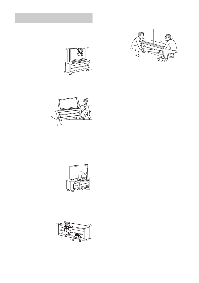
WARNING
Do not lean on or hang from the
TV when the TV is placed on the
stand.
The TV may fall from the
stand causing an accident
resulting in serious injury or
death.
Do not move the stand with the
TV or other equipment installed
on it.
Be sure to remove
the TV and other
equipment when
moving the stand. If
you fail to do so, the
stand may lose
balance and topple
over resulting in serious injury.
Do not allow the AC power cord
(mains lead) or the connecting
cable to be pinched between the
TV and the stand.
• The AC power cord (mains lead)
or the connecting cable may be
damaged resulting in fire or
electric shock.
• When moving the stand, be
careful not to trap the AC power
cord (mains lead) or the
connecting cable under the stand.
Do not allow children to climb on
the stand or crawl between the
shelves.
If children climb on the
stand or get between
the shelves, serious
injury or death can
result if the gla ss breaks
or the stand topples
over.
Do not hold the base when
moving the stand.
When you move
the stand, hold
the lower pa rt of
the top shelf. If
you hold the
base as in the
illusration, there
is a risk that the
plinth section
may detach and the stand may fall.
Top shelf
GB
4
Page 5
CAUTION
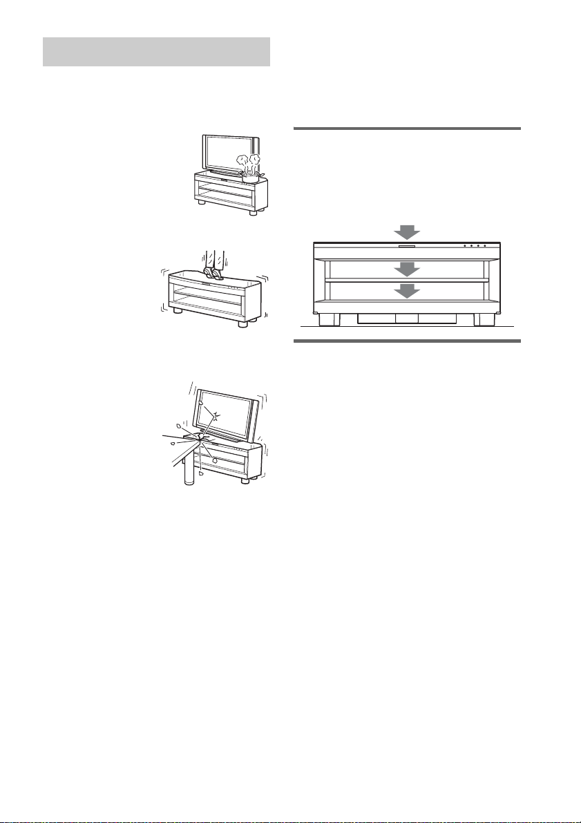
Do not place any heated objects
such as a hot pan or a kettle on
the stand.
A top glass panel may break
and cause injury. Or, it may
cause damage to the stand.
Do not step on the stand.
You may fall, or break
the glass and cause
injury.
This stand is only for the
specified TV.
Confirm whether this stand is mentioned as a
supported product in the operating instructions
of the TV.
Note on load capacity
Do not place any equipment exceeding the
specified maximum weight on the stand, as
indicated in the illustration below. Otherwise, it
may fall or break.
50 kg
14 kg
25 kg
Do not subject the top glass panel
to excessive shock.
This stand uses glass
with an anti-scatter
film, but care should
still be taken. If the
glass breaks, glass
fragments could cause
injury, so observe the
precautions below.
• Do not hit the glass or
drop sharp-pointed objects on the glass. Avoid
excessive shock.
• Do not scratch or poke the glass with sharp-pointed
objects.
• Do not hit a compon ent on the upper side of a top glass
panel when installing the component.
Do not use the top glass panel if it
is cracked.
Do not use the top glass panel when it is cracked.
The top glass panel may break and cause severe
injury.
Notes on installation
• Be careful not to pinch your hand or fingers between
the TV and the stand.
• To prevent the stand from distorting, observe the
following:
– Install the stand on a solid and flat surface.
– If you install the stand on a soft surface such as a
mat, first lay a board under the stand.
– Do not install the stand in a place subject to direct
sunlight or near a heater.
– Do not install the stand in a hot or humid place, or
outdoors.
• Moving the stand requires two people or more. Move
the stand only after removing the TV. If you fail to do
so, the TV may fall from the stand resulting in serious
injury. Do not hold the grille as it may detac h from the
stand resulting in serious injury. Be careful not to
pinch your fingers when moving the stand.
GB
5
Page 6

Precautions
On safety
• Do not place unspecified objects, such as a flower
vase or pottery on the stand.
• Do not make alterations to the stand.
• Should any solid object or liquid fall into the stand,
unplug the stand and have it checked by qualified
personnel before operating it any further.
On power sources
• Before operating the stand, check that the operating
voltage is identical to your local power supply. The
operating voltage is indicated on the nameplate at the
rear of the stand.
• The stand is not disconnected from the AC power
source (mains) as long as it is connected to the wall
outlet (mains), even if the stand itself has been turned
off.
• If you are not going to use the stand for a long time,
be sure to disconnect the stand from the wall outlet
(mains). To disconnect the AC power cord (mains
lead), grasp the plug itself; never pull the cord.
• One blade of the plug is wider than the other for the
purpose of safety and will fit into the wall outlet
(mains) only one way. If you are unable to insert the
plug fully into the outlet, contact your dealer.
• AC power cord (mains lead) must be changed only at
the qualified service shop.
• As the main plug is used to disconnect the unit from
the mains, connect the unit to an easily accessible AC
outlet. Should you notice an abnormality in the unit,
disconnect the main plug from the AC outlet
immediately.
On placement
• Place the stand in a location with adequate ventilation
to prevent heat buildup and prolong the life of the
stand.
• Use caution when placing the stand on surfaces that
have been specially treated (with wax, oil, polish, etc.)
as staining or discoloration of the surface may result.
• The floor may be damaged if sand, trash, etc., gets
caught under the legs of the stand.
On operation
Before connecting other compon ents, be sure to turn off
and unplug the stand.
On cleaning
Clean the stand, panel and controls with a soft cloth
slightly moistened with a mild detergent solution. Do
not use any type of abrasive pad, scouring powder or
solvent such as alcohol or benzine.
If you have any question or problem concerning your
stand, please consult your nearest Sony dealer.
Copyrights
This stand incorporates Dolby* Digital and Pro Logic
Surround and the DTS** Digital Surround System.
* Manufactured under license from Dolby
Laboratories.
Dolby, Pro Logic and the double-D symbol are
trademarks of Dolby Laboratories.
** Manufactured under license under U.S. Patent #'s:
5,451,942; 5,956,674; 5,974,380; 5,978,762;
6,487,535 & other U.S. and worldwide patents
issued & pending. DTS and DTS Digital Surround
are registered trademarks and the DTS logos and
Symbol are trademarks of DTS, Inc. © 1996-2008
DTS, Inc. All Rights Reserved.
This stand incorporates High-Definition Multimedia
Interface (HDMI™) technology.
HDMI, the HDMI logo and High-Definition
Multimedia Interface are trademarks or registered
trademarks of HDMI Licensing LLC.
“BRAVIA” is a trademark of Sony Corporation.
“PlayStation” is a trademark of Sony Computer
Entertainment Inc.
GB
6
Page 7
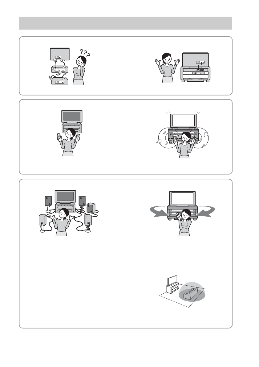
Main features
B Easy connection with HDMI
b
The cords are all tangled up. Neat connections (page 13).
B Easy operation with only one TV remote (“BRAVIA” Sync)
b
Separate remotes for each component. Consolidate operations on one remote
(page 30).
B Easy Surround settings
b
I need lots of cords and speakers. Easy set-up with S-Force PRO Front
Surround.
About S-Force PRO Front Surround
Sony’s long-term involvement in surround
technology (and the vast amounts of acoustic data
accumulated as a result) has led to the
development of all-new processing method and
advanced DSP to handle this task effectively,
which we call S-Force PRO Front Surround.
Compared with previous front surround
technologies, S-Force PRO Front Surround
reproduces a more convincing sense of distance
and space, resulting in a true surround sound
experience without the need for rear speakers.
Recommended surround-sound area
You can enjoy surround sound in the areas in
which sound is spread as illustrated.
GB
7
Page 8
Getting Started
Supplied accessories
Please check the following accessories in the
package.
Optical cable (1)
Remote commander (RM-ANU032) (1)
Size AA (R6) batteries (2)
Screw for the support belt (1)
Cable ties (2)
Shelf board (1)
Shelf support pins (4)
FM wire antenna (aerial) (1)
AM loop antenna (aerial) (1)
Operating Instructions (1)
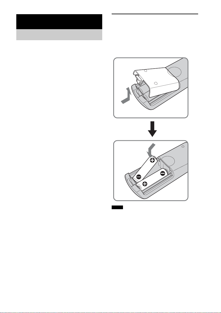
Inserting batteries into the
remote
You can control the stand using the supplied
remote. Insert two size AA (R6) batteries by
matching the + and – ends on the batteries to the
markings inside the compartment.
Notes
• Do not leave the remote in an extremely hot or humid
place.
• Do not use a new battery with an old one.
• Do not drop any foreign object into the remote casing,
particularly when replacing the batteries.
• Do not expose the remote sensor to direct light from
the sun or lighting apparatus. Doing so may cause a
malfunction.
• If you do not intend to use the remote for an extended
period of time, remove the batteries to avoid possible
damage from battery leakage and corrosion.
GB
8
Page 9
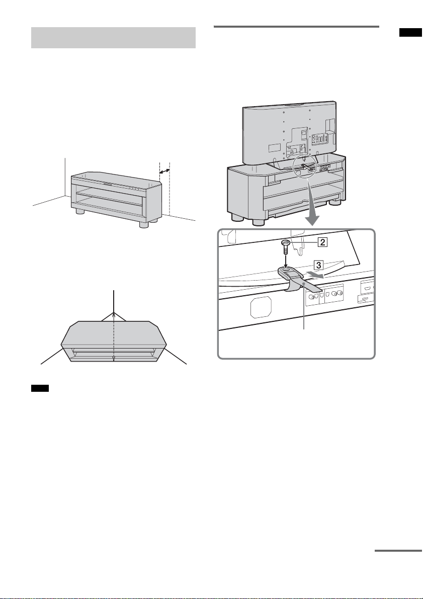
Setting this stand
About the installation position
Install the stand after connecting all the
components to the stand.
Install the stand after allowing for a space of
more than 5 cm from the wall. This is to allow
for heat dissipation and to prevent the TV from
falling.
More than
5cm
The stand has a back corner cut to fit in the
corner of a room. If you install the stand in a
corner of your room, it requires a space of about
86 cm from the corner of the room to the front of
the stand.
Preventing the TV from
toppling over
As a protective measure, secure the TV.
Perform following steps as a protective measure
if you have a Sony LCD TV.
Getting Started
86 cm
Note
• Be careful not to pinch your fingers when setting up
the stand.
Support belt
1 Place the TV on the stand.
The TV should be placed in the centre of the
stand, aligning the rear edge of the TV’s
base with the stand’s rear edge.
2 Fix the support belt to the TV firmly.
The support belt is attached on the rear of
the stand. Place the tip of the support belt on
the TV, then insert and tighten the screw for
the support belt (supplied), using a coin, etc.
3 Pull the support belt against the TV to
secure the TV firmly to the stand.
continued
9
GB
Page 10
Installing the shelf board
1 Insert the attaching shelf support pins
(supplied) into the holes in the stand.
2 Fit the shelf board onto the shelf
support pins horizontally.
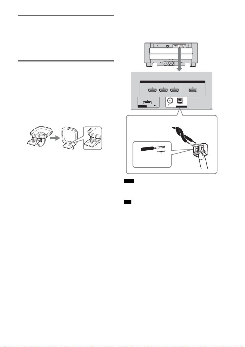
Connecting the AM loop
antenna (aerial)
The shape and the length of the antenna (aerial)
are designed to receive AM signals. Do not
dismantle or roll up the antenna (aerial).
1 Remove only the loop part from the
plastic stand.
2 Set up the AM loop antenna (aerial).
3 Connect the cords to the AM antenna
(aerial) terminals.
The cords can be connected to either
terminal.
HDMI
SAT/CATV
IN
DC 5V
DMPORT
0.7A MAX
Insert the cords by pushing down the terminal
clamp.
Insert until this
part.
Note
75 COAXIAL
FM
BD IN
• Do not place the AM loop antenna (aerial) near the
system or other AV component, as noise may result.
Tip
• Adjust the direction of the AM loop antenna (aerial)
for best AM broadcast sound.
AM
ANTENNA
TV OUTDVD I N
4 Make sure the AM loop antenna (aerial)
is connected firmly by pulling softly.
10
GB
Page 11
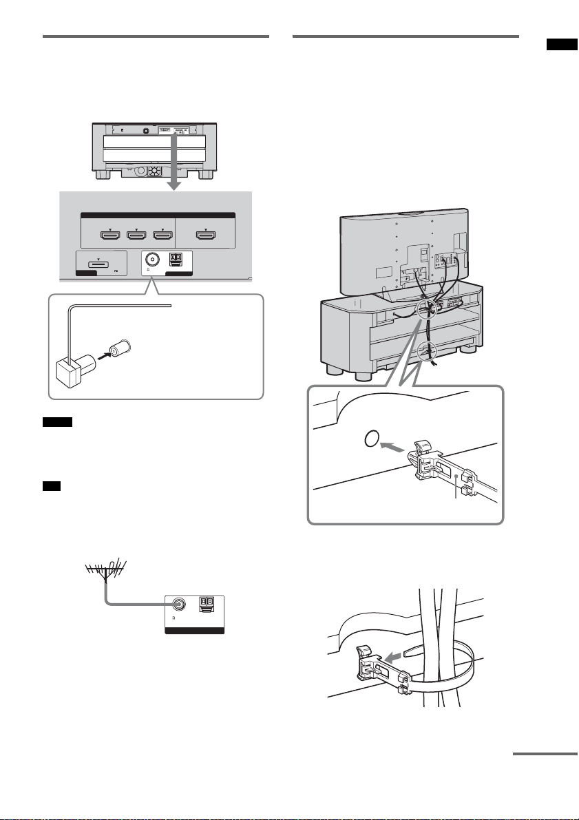
Connecting the FM wire
antenna (aerial)
Connect the FM wire antenna (aerial) to the
75 Ω COAXIAL jack.
HDMI
Bundling the cables
You can bundle all connecting cables of the
stand and other components, using the cable ties
(supplied).
1 Connect the components to the stand.
For details, refer to pages 13 to 17.
2 Insert a cable tie (supplied) into each of
the two holes at the rear of the stand
until they click.
Getting Started
DMPORT
SAT/CATV
DC 5V
0.7A MAX
75 COAXIAL
FM
BD IN
IN
AM
ANTENNA
TV OUTDVD I N
FM wire antenna (aerial)
(supplied)
75 Ω COAXIAL jack
Notes
• Be sure to fully extend the FM wire antenna (aerial).
• After connecting the FM wire antenna (aerial), keep it
as horizontal as possible.
Tip
• If you have poor FM reception, use a 75-ohm coaxial
cable (not supplied) to connect the control unit to an
outdoor FM antenna (aerial) as shown below.
Outdoor FM antenna (aerial)
75 COAXIAL
FM AM
ANTENNA
Rear of the stand
Cable tie
3 Bundle the cables, and then insert the
end of the cable tie through the slit of
the cable tie.
continued
11
GB
Page 12
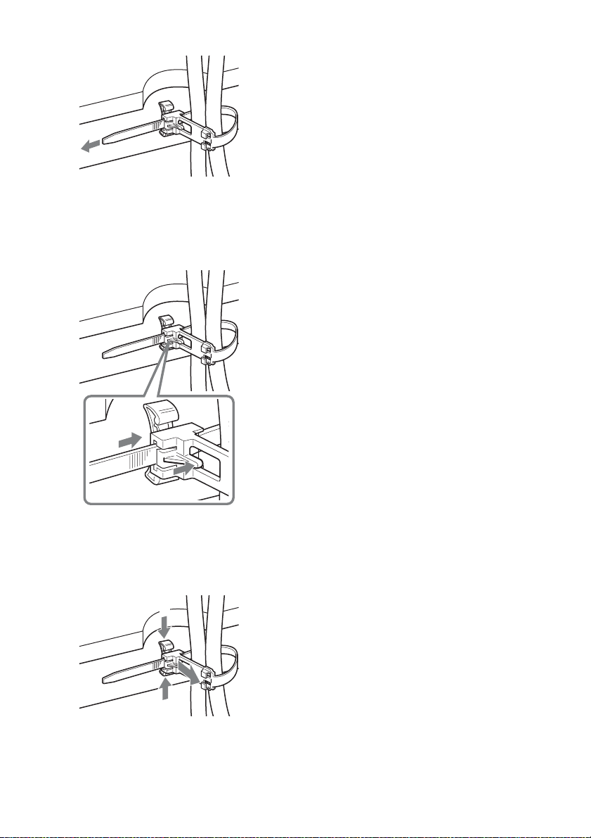
4 Tighten the cable tie by pulling its end.
To unbind the cable tie
1 Push the lever of the cable tie.
2 While pushing the lever, pull the cable tie
from the slit.
2
1
To remove the cable tie from the
rear of the stand
1 Pinch the two tabs of the cable tie.
2 While pinching the tabs, pull off the cable tie.
1
2
1
GB
12
Page 13
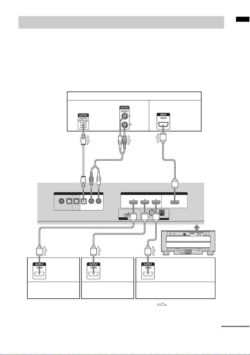
Connecting components with HDMI jacks
We recommend that you connect components to
the stand using an HDMI cable.
With HDMI, you can easily enjoy both high
quality sound and high quality images.
However, you cannot enjoy the TV’s sound
from the stand only with HDMI connection. It
is necessary to connect the audio output of the
TV to the audio input of the stand using an
optical cable or an audio cord in order listen
Audio signal
or
to the TV’s sound from the stand.
By connecting Sony “BRAVIA” Synccompatible components using HDMI cables,
““BRAVIA” Sync Features” makes
operations simpler (page 30).
Connect the AC power cord (mains lead) after
you have finished connecting all components to
the stand.
TV monitor, projector, etc.
Getting Started
Audio/video signal
SAT/CATV
DVD
Audio/video
signal
Satellite tuner,
cable television tuner, etc.
A HDMI cable (not supplied)
B Optical cable (supplied)
C Audio cord (not supplied)
CB
ANALOG
OPTOPTOPTCOAX
RL
TV
DMPORT
Audio/video
signal
DVD player (recorder), etc.
SAT/CATV
IN
DC 5V
0.7A MAX
A
HDMIINPUT
AM
ANTENNA
TV OUTDVD I N
75 COAXIAL
FM
BD IN
AAA
Audio/video
signal
Blu-ray Disc player (recorder),
“PlayStation 3,” etc.
: Signal flow
continued
13
GB
Page 14

Tip
• Even if the stand is turned off (active standby mode),
the HDMI signal will be sent from the connected
component to the TV via the HDMI connection. You
can enjoy image and sound of the component on the
TV.
Notes
• The HDMI jack has priority when you connect the
component to the stand using INPUT OPT, INPUT
COAX and HDMI together.
• The INPUT OPT jack has priority when you connect
both the audio output of the TV to the INPUT OPT
and INPUT ANALOG jack of the stand.
Notes on HDMI connections
• You can enjoy high quality images using an
HDMI cable with an HDMI logo. We
recommend that you use a Sony HDMI cable.
• Check the setup of the connected component if
an image is poor or the sound does not come
out of a component connected via the HDMI
cable.
• Audio signals (sampling frequency, bit length,
etc.) transmitted from an HDMI jack may be
suppressed by the connected component.
• Sound may be interrupted when the sampling
frequency or the number of channels of audio
output signals from the playback component is
switched.
• When the connected component is not
compatible with copyright protection
technology (HDCP), the image and/or the
sound from the HDMI TV OUT jack may be
distorted or may be not output.
In this case, check the specification of the
connected component.
• We do not recommend using an HDMI-DVI
conversion cable.
• When “TV,” “FM,” “AM,” or “DMPORT” is
selected for the input source of the stand, video
signals via the HDMI input jack (SAT/CATV,
DVD, BD) that was selected last time are
output from the HDMI TV OUT jack.
14
GB
Page 15
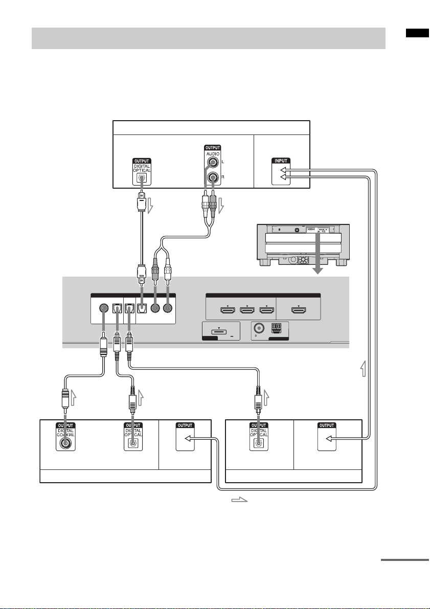
Connecting components without HDMI jacks
When you connect a DVD player (recorder),
satellite tuner, “PlayStation 2,” etc., that has no
HDMI jacks, connect its video signal jack
directly to the TV, and its audio signal jack to the
stand using the INPUT OPT jack or INPUT
COAX jack.
TV monitor, projector, etc.
It is not necessary to connect all the cables.
Connect the audio cords according to the jacks of
your components.
Connect the AC power cord (mains lead) last.
Getting Started
Audio signal
Video signal
or
CB
75 COAXIAL
FM
HDMIINPUT
BD IN
AM
ANTENNA
TV OUTDVD I N
SAT/CATV
ANALOG
OPTOPTOPTCOAX
DMPORT
SAT/CATV
IN
DC 5V
0.7A MAX
RL
DVD
TV
Video signal
D
AA
or
Satellite tuner, cable television tuner, etc.
A Optical cable (not supplied)
B Optical cable (supplied)
C Audio cord (not supplied)
D Coaxial digital cord (not supplied)
Video signalAudio signal
Video signalAudio signal
DVD player (recorder), “PlayStation 2,” etc.
: Signal flow
continued
GB
15
Page 16

Notes
• Set “CTRL: HDMI” to “OFF” in the AMP menu of
the stand when connecting components without
HDMI jacks (page 32).
Even if “CTRL: HDMI” is set to “ON,” you can enjoy
a video cassette recorder, etc., that does not have
surround channels by connecting its audio and video
output jacks directly to the TV instead of the stand.
• The INPUT OPT jack has priority when you connect
both the audio output of the TV to the INPUT OPT
and INPUT ANALOG jack of the stand.
Setting up the sound output of the connected component
Depending on the audio output settings of the
connected component, the sound may output in 2
channel sound format only. In this case, set the
connected component to output the sound in
multi channel sound format (PCM, DTS, Dolby
Digital). For details on audio output settings,
refer to the operating instructions supplied with
the connected component.
16
GB
Page 17

Connecting the DIGITAL MEDIA PORT adapter
Getting Started
You can enjoy sound from the connected
component on the stand by connecting the
DIGITAL MEDIA PORT adapter.
ANALOG
OPTOPTOPTCOAX
SAT/CATV
: Signal flow
DIGITAL MEDIA PORT adapter
Notes
• Do not connect or disconnect the DIGITAL MEDIA
PORT adapter while the stand is turned on.
• When you connect the DIGITAL MEDIA PORT
adapter, be sure the connector is inserted with the
arrow mark facing toward the arrow mark on the
DMPORT jack. To detach the DIGITAL MEDIA
PORT adapter, press and hold
connector.
RL
DVD
TV
A and then pull out the
Connect the AC power cord (mains lead) last.
HDMIINPUT
DMPORT
SAT/CATV
DC 5V
0.7A MAX
75 COAXIAL
FM
BD IN
IN
AM
ANTENNA
TV OUTDVD I N
A
GB
17
Page 18

Playback Options
Index to parts and controls
For more information, refer to the pages indicated in parentheses.
Front panel display Front panel buttons and indicator
Front panel buttons and indicator
POWER/
ACTIVE STANDBY
A POWER/ACTIVE STANDBY indicator
Lights as follows:
Green: The stand is turned on.
Amber: Control for HDMI function is
working while the stand is turned
off.
Off: The stand is turned off, and the
Control for HDMI function is not
working.
GB
18
INPUT SELECTOR
B ?/1 (on/standby)
VOLUME
Press to turn the stand on or off.
C INPUT SELECTOR
Press to select the input source to play back.
Each time you press the button, the input
source changes cyclically as follows:
TV t BD t DVD t SAT/CATV t FM
t AM t DMPORT t TV …..
D VOLUME +/–
Press to adjust the volume.
Page 19

Front panel display
About the indications in the front panel display
A Audio format indicators
Light up according to the audio format that
is being decoded.
B SLEEP (39)
Flashes when the Sleep Timer function is
active.
C TUNED (23)
Lights up when a radio station is received.
D HDMI (13, 41)
Lights up when an HDMI equipment is
being used.
E ST/MONO (23)
Lights up according to the stereo or
monaural status of the radio.
F COAX/OPT
Lights up according to the cable which you
are using.
G (remote sensor) (41)
Point the remote commander towards here.
H MUTING
Lights up when the sound is turned off.
I Message display area
Displays volume, selected input source,
audio input signal, etc.
J NIGHT (29)
Lights up in NIGHT mode.
Playback Options
continued
19
GB
Page 20

Remote control
INPUT SELECTOR
CENTER SUBWOOFER
LEVEL
DISPLAY
RETURN
PRESET-NIGHT
TUNING
MUTING
VOLUME
Buttons for the operation of this
stand
A ?/1 (on/standby)
Press to turn the stand on or off.
B LEVEL
Press to adjust the level of the center speaker
and subwoofer. This setting is applied to all
sound fields.
C AMP MENU
Press to display the menu of the stand
(page 36).
D C, X, x, c or
Press C, X, x or c to select the settings.
Then press to enter the selection.
E MENU
Press to preset a radio station or name the
preset station (page 23, 25).
F DIMMER
Press to select the brightness of the front
panel display. It can be set to one of two
levels.
G TUNING +/–
Press to select a radio station (page 23, 24).
-
AMP MENU
PRESET+
DIMMER
TUNING
SOUND FIELD
MENU
+
I SOUND FIELD +/–
Press to select the sound field (page 27).
J VOLUME +/–
Press to adjust the volume.
K MUTING
Press to turn off the sound.
L NIGHT
Press to activate the NIGHT mode function
(page 29).
M PRESET +/–
Press to select a preset radio station
(page 24).
N O RETURN
Press to return to the previous menu.
O DISPLAY
Press to switch the information in the front
panel display.
P INPUT SELECTOR +/–
Press to select an input source, such as the
tuner, or other connected component.
Each time you press the button, the input
source changes cyclically as follows:
TV y BD y DVD y SAT/CATV y
FM y AM y DMPORT y TV …..
Buttons for the operation of a
connected component through
DMPORT connection
D C, X, x, c or
Press to select a menu item and enter the
selection.
E MENU
Press to display the MENU.
G m/M
Press to fast reverse or to fast forward the
disc when pressed during playback.
H N (playback)/X (pause)/x (stop)
Play mode buttons.
M ./>
Press to skip chapters.
N O RETURN
Press to return to the previous menu.
O DISPLAY
Press to select the setting of the front panel
display.
20
GB
Page 21

Enjoying TV
Enjoying other
INPUT
SELECTOR
+/–
INPUT SELECTOR
CENTER SUBWOOFER
LEVEL
DISPLAY
RETURN
PRESET-NIGHT
-
TUNING
MUTING
VOLUME
AMP MENU
PRESET+
DIMMER
TUNING
SOUND FIELD
MENU
?/1
+
VOLUME
+/–
1 Turn on the TV and choose a program.
Refer to the operating instructions of your
TV for details.
2 Turn the stand on.
3 Press INPUT SELECTOR + or –
repeatedly until “TV” appears in the
front panel display.
4 Adjust the volume by pressing
VOLUME +/–.
Tip
• The sound may be output from the TV’s speaker. In
this case, turn the volume of the TV’s speaker down
to the minimum.
components
INPUT SELECTOR
INPUT
SELECTOR
+/–
CENTER SUBWOOFER
DISPLAY
RETURN
PRESET-NIGHT
-
TUNING
MUTING
VOLUME
LEVEL
DIMMER
SOUND FIELD
AMP MENU
MENU
PRESET+
TUNING
VOLUME
+/–
Enjoying a satellite tuner or
cable television tuner
?/1
+
1 Turn on the TV.
Refer to the operating instructions of your
TV for details.
2
Turn the satellite/cable television tuner
and stand on.
3 Press INPUT SELECTOR + or –
repeatedly until “SAT/CATV” appears
in the front panel display.
4 Change the TV input.
Refer to the operating instructions of your
TV for details.
5 Adjust the volume by pressing
VOLUME +/–.
Playback Options
continued
21
GB
Page 22

Tip
• The sound may be output from the TV’s speaker. In
this case, turn the volume of the TV’s speaker down
to the minimum.
Enjoying Blu-ray Disc, DVD,
“PlayStation 2” or
“PlayStation 3”
1 Turn on the TV.
2 Turn the Blu-ray Disc/DVD player
(recorder), “PlayStation 2” or
“PlayStation 3” and the stand on.
3 Press INPUT SELECTOR + or –
repeatedly until “BD” or “DVD” appears
in the front panel display.
4 Change the TV input.
Refer to the operating instructions of your
TV for details.
5 Play back the disc.
Tip
• Even if you playback Dolby True HD, Dolby Digital
Plus or DTS HD with a connected component
compatible with these sound formats, the stand
accepts as Dolby Digital or DTS. When you playback
these high-quality sound formats, set the connected
component to output the sound in multi channel PCM,
if possible.
Notes
• When you connect the video output jack of the
DIGITAL MEDIA PORT adapter to the video input
jack of the TV, set “CTRL: HDMI” to “OFF” in the
AMP menu of the stand (page 32). The images of a
component connected to the DIGITAL MEDIA
PORT adapter will not be played on the TV if “CTRL:
HDMI” is set to “ON.”
• To enjoy the sound of a component without
displaying the images when “CTRL: HDMI” is set to
“ON,” turn off the TV first and then reset the power of
the stand.
If you turn on this stand first and then turn off the TV,
all components connected to the TV will be turned off
because of the Control for HDMI function.
Enjoying a connected
component through DMPORT
connection
1 Press INPUT SELECTOR + or –
repeatedly until “DMPORT” appears in
the front panel display.
2 Start playback of the connected
component.
Tip
• You can enjoy optimum sound quality from portable
audio components in any sound field except for
“STANDARD,” joining the effect of Portable Audio
Enhancer.
GB
22
Page 23

Tuner Functions
Presetting radio stations
5 Press .
A preset number appears in the front panel
display.
You can preset 20 FM stations and 10 AM
stations. Before tuning, make sure to turn down
the volume to minimum.
INPUT SELECTOR
INPUT
SELECTOR
+/–
C, X, x, c,
CENTER SUBWOOFER
LEVEL
DISPLAY
RETURN
PRESET-NIGHT
-
TUNING
MUTING
VOLUME
AMP MENU
PRESET+
DIMMER
TUNING
SOUND FIELD
MENU
MENU
+
TUNING
+/–
1 Press INPUT SELECTOR + or –
repeatedly until “FM” or “AM” appears
in the front panel display.
2 Press and hold TUNING + or – until the
auto scanning starts.
Scanning stops when the system tunes in a
station. “TUNED” and “ST” (for stereo
program) light up in the front panel display.
“MONO” lights up for a monaural program.
3 Press MENU.
4 Press X/x repeatedly until “Memory?”
appears in the front panel display.
6 Press X/x to select the preset number
you want.
7 Press .
“Complete!” appears in the front panel
display, and the station is stored.
8 Press MENU.
9 Repeat 2 to 8 to store other stations.
To change the preset number
Restart from step 3.
Tuner Functions
23
GB
Page 24

Listening to the radio
Preset radio stations in the stand’s memory first
(see “Presetting radio stations” (page 23)).
INPUT
SELECTOR
+/–
DISPLAY
C, X, x , c,
VOLUME
+/–
INPUT SELECTOR
CENTER SUBWOOFER
LEVEL
DISPLAY
RETURN
PRESET-NIGHT
-
TUNING
MUTING
VOLUME
AMP MENU
PRESET+
DIMMER
TUNING
SOUND FIELD
MENU
?/1
MENU
PRESET
+
+/–
TUNING
+/–
1 Press INPUT SELECTOR + or –
repeatedly until “FM” or “AM” appears
in the front panel display.
The last received station is tuned in.
2 Press PRESET + or – repeatedly to
select the preset station.
Each time you press the button, the stand
tunes in one preset station.
3 Adjust the volume by pressing
VOLUME +/–.
To turn off the radio
Press "/1 to turn off the stand.
To change to another function, press INPUT
SELECTOR + or –.
To listen to non-preset radio
stations
Use manual or automatic tuning in step 2.
For manual tuning, press TUNING + or –
repeatedly.
For automatic tuning, press and hold TUNING +
or –. The automatic tuning stops when the stand
tunes in a station. To stop the automatic tuning
manually, press TUNING + or –.
If an FM program is noisy
If an FM program is noisy, you can select
monaural reception. There will be no stereo
effect, but reception will improve.
1 Press MENU.
2 Press X/x repeatedly until “FM Mode?”
appears in the front panel display, then press
or c.
3 Press X/x to select “MONO.”
• STEREO: Stereo reception.
• MONO: Monaural reception.
4 Press .
The setting is made.
5 Press MENU.
Tip
• To improve reception, reorient the FM wire antenna
(aerial) (supplied).
24
GB
Page 25

Naming preset stations
You can enter a name for preset stations. These
names (for example, “XYZ”) appear in the front
panel display when a station is selected.
Note that no more than one name can be entered
for each preset station.
1 Press INPUT SELECTOR + or –
repeatedly until “FM” or “AM” appears
in the front panel display.
The last received station is tuned in.
2 Press PRESET + or – repeatedly to
select the preset station you want to
create an index name for.
3 Press MENU.
4 Press X/x repeatedly until “Name In?”
appears in the front panel display.
5 Press .
6 Create a name by using C/X/x/c.
Press X/x to select a character, then press c
to move the cursor to the next position.
Letters, numbers, and other symbols can be
input for a radio station name.
If you enter a wrong character
Press C/c repeatedly until the character to
be changed flashes, then press X/x to select
the desired character.
7 Press .
“Complete!” appears in the front panel
display, and the station name is stored.
Viewing the station name or
frequency in the front panel
display
When the stand is set to “FM” or “AM,” you can
check the frequency using the front panel
display.
Press DISPLAY.
Each time you press DISPLAY, the station name
and the frequency alternate in the front panel
display.
Tips
• The station name is displayed if you have entered a
name for a preset station.
• The frequency in the front panel display switches to
the station name after several seconds.
Tuner Functions
8 Press MENU.
Tip
• You can check th e frequency in the front panel display
by pressing DISPLAY repeatedly (page 25).
25
GB
Page 26

Using the Radio Data System (RDS)
What is the Radio Data
System?
The Radio Data System (RDS) is a broadcasting
service that allows radio stations to send
additional information along with the regular
program signal. This tuner offers convenient
RDS features, such as station name display. RDS
is available only for FM stations.*
Note
• RDS may not work properly if the station you are
tuned to is not transmitting the RDS signal properly,
or if the signal strength is weak.
* Not all FM stations provide RDS service, nor do
they provide the same type of services. If you are not
familiar with the RDS system, check with your local
radio stations for details on RDS services in your
area.
Receiving RDS broadcasts
Simply select a station from the FM band.
When you tune in a station that provides RDS
services, the frequency in the front panel display
switches to the station name*.
* If an RDS broadcast is not received, a station name
will not appear in the front panel display.
Tip
• When a station name is displayed, you can check the
frequency by pressing DISPLAY repeatedly.
26
GB
Page 27

Surround Function
Enjoying the surround effect
Selecting the sound field
This stand can create multi channel surround sound. You can select one of stand’s optimized preprogrammed sound fields.
INPUT SELECTOR
CENTER SUBWOOFER
LEVEL
DISPLAY
AMP MENU
Surround Function
RETURN
PRESET-NIGHT
-
TUNING
MUTING
VOLUME
PRESET+
DIMMER
TUNING
SOUND FIELD
MENU
+
SOUND
FIELD +/–
Press SOUND FIELD +/–.
The present sound field appears in the front panel display.
Each time you press the SOUND FIELD +/– button, the display changes cyclically as follows:
STANDARD y MOVIE y DRAMA y NEWS y SPORTS y GAME y MUSIC y JAZZ
y CLASSIC y ROCK y POP y LIVE y FLAT y STANDARD …..
continued
27
GB
Page 28

Available sound fields
Suitable source Sound field Effect
All STANDARD Suits various sources.
Video source MOVIE * Recreates powerful and realistic sound, along with clear dialog.
DRAMA * Best suited for TV dramas.
NEWS * Produces the announcer’s voice clearly.
SPORTS * Produces the play-by-play commentary clearly and realistic
GAME * Produces powerful and realistic sound, best suited for playing
MUSIC* Best suited for music programs or music videos on Blu-ray Discs/
Music source JAZZ Recreates the atmosphere of a jazz club.
CLASSIC Recreates the atmosphere of a classical concert.
ROCK Produces powerful sound, best suited for listening to rock music.
POP Produces uplifting sound, best suited for listening to pop music.
LIVE Recreates the atmosphere of a live performance.
FLAT Plays all music in stereo without any effects.
* These sound fields are not available when “DMPORT” is selected by pressing INPUT SELECTOR.
Tips
• You can set a different sound field for each input source.
• The sound field default setting for “DMPORT” is “FLAT,” and for other sources “STANDARD”.
• When “DMPORT” is selected by pressing INPUT SELECTOR, the center speaker produces no sound.
• Some speakers will not produce sound depending on the input signal, such as monaural programmes.
• The center speaker produces no sound in any sound field suitable for a music source.
• If you press the THEATRE button on a Sony TV remote when “CTRL: HDMI” is set to “ON,” the sound field
changes to “MOVIE” (some Sony TVs excluded).
sound with surround effects, such as cheering, etc.
video games.
DVDs.
28
GB
Page 29

Enjoying the sound at low
volume (NIGHT mode)
You can enjoy sound effects and to hear the
dialog clearly even at a low volume level using
this function. This function is useful for enjoying
sound at night.
INPUT SELECTOR
CENTER SUBWOOFER
LEVEL
NIGHT
DISPLAY
RETURN
PRESET-NIGHT
TUNING
MUTING
VOLUME
-
AMP MENU
PRESET+
DIMMER
TUNING
SOUND FIELD
MENU
+
Press NIGHT.
To cancel the night mode, press NIGHT again.
Tip
• You can listen to Dolby Digital sound at low volume
by using AUDIO DRC (page 38).
Surround Function
29
GB
Page 30

“BRAVIA” Sync Features
What is “BRAVIA” Sync?
By connecting Sony components that are
compatible with the “BRAVIA” Sync with an
HDMI cable (not supplied), operation is
simplified as below:
• One-Touch Play: When you play back a
component such as a Blu-ray Disc/DVD player
(recorder), the TV turns on automatically and
switches to the appropriate HDMI input.
• System Audio Control: While watching TV,
you can select to output the sound from the TV
speaker or the speakers of the stand.
• System Power Off: When you turn off the TV,
the stand and the connected components are
also turned off simultaneously.
“BRAVIA” Sync is compatible with a Sony TV,
Blu-ray Disc/DVD player, AV amplifier, etc.,
with the Control for HDMI function.
CONTROL FOR HDMI is a mutual control
function standard used by CEC (Consumer
Electronics Control) for HDMI (High-Definition
Multimedia Interface).
The Control for HDMI function will
not operate correctly in the
following cases:
• When you connect this stand to a component
which is not correspond with Control for
HDMI function.
• When you connect the stand and components
using other than HDMI connection.
We recommend that you connect this stand to
products featuring “BRAVIA” Sync.
Note
• Depending on the connected component, the Control
for HDMI function may not work. See the operating
instructions of the component.
Preparing for the “BRAVIA” Sync
To use the “BRAVIA” Sync, set the Control for
HDMI function to on for the connected
component.
When you connect a Sony TV with the Control
for HDMI function, the Control for HDMI
function for the stand and the connected
component can be set simultaneously by setting
Control for HDMI function of the TV.
C, X, x, c,
INPUT SELECTOR
CENTER SUBWOOFER
DISPLAY
RETURN
PRESET-NIGHT
-
TUNING
MUTING
VOLUME
LEVEL
DIMMER
SOUND FIELD
AMP MENU
MENU
PRESET+
TUNING
?/1
AMP
MENU
+
1 Make sure that the stand is connected
to the TV and the connected
components (which should be
compatible with the Control for HDMI
function) using HDMI cables (not
supplied).
2 Turn on the stand, the TV and the
connected components.
3 Select the input of the stand connected
to the component you want to watch
(SAT/CATV, DVD, BD), and switch the
HDMI input of the TV, so that an image
from the connected component is
displayed.
30
GB
Page 31

4 Display the list of the HDMI
components on the TV menu, and set
the Control for HDMI function to on for
connected components.
The Control for HDMI function for the
stand and the connected component is
simultaneously set to on.
During the setting, “SCANNING” appears
in the front panel display. After you finish
the setting, “COMPLETE” appears in the
front panel display. Wait until the setting is
complete.
Note
• For details on setting the TV and the connected
components, refer to their operating instructions.
If “SCANNING” or “COMPLETE”
does not appear after performing
the steps above
Set the Control for HDMI function to on for the
stand and the connected component individually.
1 Press AMP MENU.
2 Press X/x repeatedly until “SET HDMI”
appears, then press or c.
3 Press X/x repeatedly until “CTRL:
HDMI” appears, then press or c.
4 Press X/x to select “ON.”
5 Press AMP MENU.
The AMP menu turns off. The Control for
HDMI function is set to on.
6 Set the Control for HDMI function of the
connected component to on.
For details on setting the connected
component, refer to its operating
instructions.
7 Select the input of the stand connected
to the component you want to use the
Control for HDMI function for (SAT/
CATV, DVD, BD), and repeat step 6.
If you add or reconnect the
component
Perform steps of “Preparing for the “BRAVIA”
Sync” and “If “SCANNING” or “COMPLETE”
does not appear after performing the steps
above” again.
Notes
• During the setting of the Control for HDMI function
for the stand, the System Audio Control function does
not work.
• If the Control for HDMI function for the connected
component cannot be set simultaneously by setting
“CONTROL FOR HDMI” of the TV, set the Control
for HDMI function using the menu of the connected
component.
• For details on setting the TV and the connected
components, refer to their operating instructions.
Tip
• The default setting of the Control for HDMI function
of the stand is “ON.”
“BRAVIA” Sync Features
continued
31
GB
Page 32

Setting the Control for HDMI
function to off
Set the Control for HDMI function to off when
you connect components not compatible with the
“BRAVIA” Sync, or that do not have HDMI
jacks, etc.
INPUT SELECTOR
CENTER SUBWOOFER
LEVEL
DISPLAY
RETURN
PRESET-NIGHT
TUNING
MUTING
VOLUME
-
AMP MENU
PRESET+
DIMMER
TUNING
SOUND FIELD
MENU
AMP
MENU
C, X, x, c,
+
Enjoying Blu-ray Disc/DVD
(One-Touch Play)
Play back a connected component.
The TV turns on automatically and switches to
the appropriate HDMI input.
Tip
• Even if the stand is turned off (active standby mode),
the HDMI signal will be sent from the connected
component to the TV via the HDMI connection. You
can enjoy image and sound of the component on the
TV.
Note
• Depending on the TV, the start of the content may not
be output.
1 Press AMP MENU.
2 Press X/x repeatedly until “SET HDMI”
appears, then press or c.
3 Press X/x to select “CTRL: HDMI,” then
press or c.
4 Press X/x to select “OFF.”
5 Press AMP MENU.
The AMP menu turns off.
GB
32
Page 33

Enjoying the TV sound from the stand
(System Audio Control)
You can enjoy the TV sound from the speakers
of the stand by means of a simple operation. For
details, see the operating instructions of the TV.
INPUT SELECTOR
CENTER SUBWOOFER
LEVEL
DISPLAY
C, X, x, c,
RETURN
PRESET-NIGHT
TUNING
MUTING
VOLUME
-
AMP MENU
PRESET+
DIMMER
TUNING
SOUND FIELD
MENU
Press ?/1 to turn on the stand.
The sound is output from the speaker of the
stand. The sound is output from the TV's speaker
when you turn the stand off.
Notes
• When the TV is turned on before this stand is turned
on, the TV sound will not be output for a moment.
• When you connect a TV that does not have System
Audio Control function, the System Audio Control
function does not work.
Tip
• You can adjust the volume and turn off the sound of
the stand using the TV remote.
?/1
AMP
MENU
+
Using the Volume Limit
function
When the System Audio Control function is
active, and the output method changes from the
TV speaker to the stand speaker automatically,
loud sound may be output depending on the
volume level of the stand. You can prevent this
by limiting the maximum volume level.
1 Press AMP MENU.
2 Press X/x repeatedly until “SET HDMI”
appears, then press or c.
3 Press X/x repeatedly until “VOL LIMIT”
appears, then press or c.
4 Press X/x to select the maximum
volume level you want.
The maximum volume level changes as
follows:
MAX y 49 y 48 ….. 2 y 1 y MIN
5 Press AMP MENU.
The AMP menu turns off.
Notes
• This function is available only when the Control for
HDMI function is set to on.
• This function is not available when the output method
changes from the stand speaker to the TV speaker.
Tips
• We recommend that you set the maximum volume
level to a little lower than the volume you usually
listen to.
• Regardless of the maximum volume level you set, the
VOLUME +/– button of the stand and the remote is
operable.
• If you do not want to limit the maximum volume
level, select “MAX.”
“BRAVIA” Sync Features
33
GB
Page 34

Turning off the stand, TV
Using the power saving
and the connected
compornents
(System Power Off)
When you turn the TV off by using the POWER
button on the TV’s remote, the stand and the
connected components turns off automatically.
Tip
• If the TV is turned off and enters standby mode, the
power consumption of the stand will be reduced when
the power saving function is on.
Note
• Depending on the status, the connected components
may not be turned off. For details, see operating
instructions supplied with the connected components.
function
If a “BRAVIA” Sync-compatible TV is
connected to the stand, and the stand is in active
standby mode, if the TV is turned off, HDMI
signal transmission stops, and power
consumption is reduced.
INPUT SELECTOR
CENTER SUBWOOFER
LEVEL
DISPLAY
RETURN
PRESET-NIGHT
TUNING
MUTING
VOLUME
-
AMP MENU
PRESET+
DIMMER
TUNING
SOUND FIELD
MENU
AMP
MENU
C, X, x, c,
+
34
1 Press AMP MENU.
2 Press X/x repeatedly until “SET HDMI”
appears, then press or c.
3 Press X/x to select “POWER SAVE,”
then press or c.
4 Press X/x to select the setting.
• ON: Reduces power consumption in
active standby mode. HDMI signal
transmission occurs only when the
TV is on.
• OFF: No reduction. HDMI signal
transmission occurs continuously
even if the stand is turned off (active
standby mode).
5 Press AMP MENU.
The AMP menu turns off.
GB
Page 35

Notes
• The power saving function may not work for some
TVs compatible with the “BRAVIA” Sync. In this
case, set “POWER SAVE” to “OFF.”
• Depending on your components, it may take time
before image or sound is output.
“BRAVIA” Sync Features
35
GB
Page 36

Advanced Settings
Settings and adjustments using the amplifier menu
Using the AMP menu
You can set the following items with AMP
MENU on the remote.
The default settings are underlined.
AMP MENU
SET
HDMI
CTRL:
*
HDMI
VOL
**
LIMIT
POWER
**
SAVE
ON
OFF
MAX, 49, 48, .....
2, 1, MIN
ON
OFF
3 Press AMP MENU to turn off the AMP
menu.
Tip
• These settings are retained even if you disconnect the
AC power cord (mains lead).
The following pages show details for each
setting.
DUAL
MONO
A/V SYNC
AUDIO
DRC
DISPLAY
SLEEP
* Refer to ““BRAVIA” Sync Features” (page 30).
** This setting appears only when “CTRL: HDMI” is
set to “ON.”
MAIN
SUB
MAIN/SUB
ON
OFF
MAX
STD
OFF
ON
OFF
OFF, 10M, 20M, …..
80M, 90M
1 Press AMP MENU to turn on the AMP
menu.
2 Press C/X/x/c repeatedly to select the
item and the setting.
GB
36
Page 37

Enjoying multiplex broadcast
sound (DUAL MONO)
You can enjoy multiplex broadcast sound when
the stand receives an AC-3 multiplex broadcast
signal.
Note
• To receive AC-3 signal, you need to connect a digital
satellite tuner to the stand with an optical cable or
coaxial cable, and set the digital output mode of the
digital satellite tuner to AC-3.
INPUT SELECTOR
CENTER SUBWOOFER
LEVEL
DISPLAY
RETURN
PRESET-NIGHT
TUNING
MUTING
VOLUME
-
AMP MENU
PRESET+
DIMMER
TUNING
SOUND FIELD
AMP
MENU
C, X, x, c,
MENU
+
1 Press AMP MENU.
2 Press X/x repeatedly until “DUAL
MONO” appears, then press or c.
3 Press X/x to select the sound you want.
• MAIN: Plays back only the main
channel.
• SUB: Plays back only the sub
channel.
• MAIN/SUB: Main sound is output from
the left speaker and sub
sound is output from the
right speaker.
4 Press AMP MENU.
The AMP menu turns off.
Adjusting the delay between
the sound and the image (A/V
SYNC)
You can delay the sound using this function
when the image is slower than the sound.
INPUT SELECTOR
CENTER SUBWOOFER
LEVEL
DISPLAY
RETURN
PRESET-NIGHT
TUNING
MUTING
VOLUME
-
AMP MENU
PRESET+
DIMMER
TUNING
SOUND FIELD
MENU
AMP
MENU
C, X, x, c,
+
1 Press AMP MENU.
2 Press X/x repeatedly until “A/V SYNC”
appears, then press or c.
3 Press X/x to select the setting.
• OFF: Does not adjust.
• ON: Adjusts the difference between
picture and sound.
4 Press AMP MENU.
The AMP menu turns off.
Notes
• You may not be able to adjust the delay between
sound and image perfectly using this function.
• This function is useful only for Dolby Digital, DTS
and Linear PCM (2ch) input by coaxial (audio),
optical (audio) or HDMI.
continued
37
Advanced Settings
GB
Page 38

Enjoying Dolby Digital sound
at low volume (AUDIO DRC)
Narrows the dynamic range of the sound track.
Useful for enjoying movies at low volume.
AUDIO DRC only applies to Dolby Digital
sources.
INPUT SELECTOR
CENTER SUBWOOFER
LEVEL
DISPLAY
RETURN
PRESET-NIGHT
TUNING
MUTING
VOLUME
-
AMP MENU
PRESET+
DIMMER
TUNING
SOUND FIELD
MENU
AMP
MENU
C, X, x, c,
+
1 Press AMP MENU.
2 Press X/x repeatedly until “AUDIO
DRC” appears, then press or c.
3 Press X/x to select the setting.
• OFF: No compression of dynamic range.
• STD: Reproduces the sound track with
the kind of dynamic range that the
recording engineer intended.
• MAX: Compresses dynamic range fully.
4 Press AMP MENU.
The AMP menu turns off.
Changing the display setting
(DISPLAY)
You can change the display setting.
INPUT SELECTOR
CENTER SUBWOOFER
LEVEL
DISPLAY
RETURN
PRESET-NIGHT
TUNING
MUTING
VOLUME
-
AMP MENU
PRESET+
DIMMER
TUNING
SOUND FIELD
AMP
MENU
C, X, x, c,
MENU
+
1 Press AMP MENU.
2 Press X/x repeatedly until “DISPLAY”
appears, then press or c.
3 Press X/x to select the setting of the
front panel display.
• ON: The display appears all the time.
• OFF: The display appears for a few
seconds when you operate the stand.
Note
• The display a ppears all the time when the muting
or protection function is working, even if you set
the “DISPLAY” to “OFF.”
4 Press AMP MENU.
The AMP menu turns off.
38
GB
Page 39

Using the sleep timer
You can set the stand to turn off at a preset time
when you sleep listening to music. You can
preset the time in 10 minutes decrements.
INPUT SELECTOR
CENTER SUBWOOFER
LEVEL
DISPLAY
RETURN
PRESET-NIGHT
TUNING
MUTING
VOLUME
-
AMP MENU
PRESET+
DIMMER
TUNING
SOUND FIELD
AMP
MENU
C, X, x, c,
MENU
+
1 Press AMP MENU.
2 Press X/x repeatedly until “SLEEP”
appears, then press or c.
3 Press X/x to select the preset time you
want.
The minutes display (remaining time)
changes as follows:
Advanced Settings
OFF y 10M y 20M
YY
90M y 80M ..... 30M
Note
• This function is only for this stand, not for the
connected TV or other components.
39
GB
Page 40

Additional Information
Troubleshooting
If you experience any of the following
difficulties while using the stand, use this
troubleshooting guide to help remedy the
problem before requesting repairs. Should any
problem persist, consult your nearest Sony
dealer.
General
The power is not turned on.
• Check that the AC power cord (mains lead)
is connected securely.
If “PROTECTOR” and “PUSH POWER”
appears alternately in the front panel display.
Press ?/1 to turn off the stand, and check the
following item after “STANDBY” disappears.
• Is anything blocking the ventilation holes of
the stand?
After checking the above item and fixing
any problems, turn on the stand. If the cause
of the problem cannot be found even after
checking the above item, consult your
nearest Sony dealer.
Dolby Digital or DTS multi-channel sound is
not reproduced.
• Check that the playing Blu-ray Disc, DVD,
etc., is recorded in Dolby Digital or DTS
format.
• When connecting the Blu-ray Disc, DVD
player, etc., to the digital input jacks of this
stand, check that audio setting (settings for
the audio output) of the connected
component.
The surround effect cannot be obtained.
• Depending on the digital signal, the
surround processing may not work
(page 27).
No sound or only a very low-level sound is
heard from the speakers.
• Press VOLUME + and check the volume
level.
• Press MUTING or VOLUME + to cancel the
muting function.
• Press SOUND FIELD +/– and check the
selected sound field.
• Depending on the source, the sound effect of
the speakers may be less noticeable.
Sound lags behind the TV image.
• Set “A/V SYNC” to “OFF” when “A/V
SYNC” is set to “ON.”
Connected components
There is no sound or only a very low-level
sound no matter which component is selected.
• Check that this stand and components are
connected correctly and securely.
• Check that both this stand and the selected
component are turned on.
There is no sound from the selected
component.
• Check that the component is connected
correctly to the audio input jacks for that
component.
• Check that the cords are fully inserted into
the jacks on both the component and this
stand.
• Check that the component is selected
correctly.
Sound is interrupted or there is noise.
• Check “Formats supported by this stand”
(page 43).
No image appears on the TV.
• Check that the TV is selected correctly.
• Set the TV to the appropriate input mode.
• Check the HDMI connection.
• Check that the cords are fully inserted into
the jacks on both the component and this
stand.
40
GB
Page 41

Control for HDMI
If you experience any of the following
difficulties while using the “BRAVIA” Sync,
use this troubleshooting guide to help you
remedy the problem.
The Control for HDMI function does not work.
• Check the HDMI connection (page 13).
• Make sure “CTRL: HDMI” is set to “ON” in
AMP menu.
• Make sure the connected component is
compatible with the Control for HDMI
function.
• Check the Control for HDMI settings on the
connected component. See the operating
instructions supplied of the connected
component.
• If you change the HDMI connection,
connect/disconnect the AC power cord
(mains lead), or there is a power failure,
repeat the procedures of ““BRAVIA” Sync
Features” (page 30).
• The stand may not work correctly if you
select a component that is not compatible
with the Control for HDMI function on the
TV side.
No sound is output from the stand and TV
speaker.
• Check the volume of the stand and the TV.
• Select the input of the stand correctly.
The sound is output from both the stand and
the TV.
• If the Control for HDMI function is set to
off, or the selected component is not
compatible with the Control for HDMI
function, turn off the sound of the stand or
the TV.
The System Power Off function does not work.
• Change the setting of the TV to turn
connected components off automatically
when you turn off the TV. For details, refer
to the operating instructions of the TV.
The stand is turned off when you turn off the
TV.
• When the Control for HDMI function is on,
the System Power Off function is active, and
the stand is turned off when you turn off the
TV.
An image does not appear on the TV.
• Check whether HDMI IN and HDMI OUT
are connected in reverse.
When the stand is in standby mode, there is no
image or sound on the TV.
• When the stand is in standby mode, image
and sound are output from the HDMI
component selected the last time you turned
off the stand. If you are enjoying other
component, play the component and
perform the One-Touch Play operation, or
turn on the stand to select the HDMI
component you want to enjoy.
• Make sure “POWER SAVE” is set to “OFF”
in the AMP menu if you connect
components not compatible with the
“BRAVIA” Sync to the stand (page 34).
OTHER
The remote does not function.
• Point the remote at the remote sensor on
the stand.
• Remove any obstacles in the path between
the remote and the stand.
• Replace both batteries in the remote with
new ones, if they are weak.
• Make sure you select the correct input on the
remote.
The volume turns down when the output
method changes from the TV speaker to the
stand speaker.
• The Volume Limit function is working. For
details, refer to “Using the Volume Limit
function” (page 33).
Additional Information
continued
41
GB
Page 42

If the stand still does not operate
properly after performing the
above measures, reset the stand
as follows:
Use buttons on the stand for the operation.
1 Press ?/1 to turn on the power.
2 Press ?/1 while pressing INPUT
SELECTOR and VOLUME –.
“COLD RESET” appears and the stand is
reset. AMP menu, sound field etc., return to
the default settings.
Specifications
42
Dimensions:
mm (approx.)
Adjustable shelf
dimensions*:
mm (approx.)
Mass: kg 49
* The shelf board can be installed at three levels (1,
2 or 3).
GB
A 1,115
B 400
C 500
123
D 86 104 122
E 123 105 87
Page 43

Formats supported by this
stand
Digital input formats supported by this stand are
as follows.
Format Supported/Not supported
Dolby Digital a
DTS a
Linear PCM-2ch* a
Linear PCM-7.1ch
48k* (Only on HDMI)
Linear PCM-7.1ch
96k
Dolby Digital Plus ×
Dolby True HD ×
DTS-HD ×
* Linear PCM accepts sampling frequencies of no
more than 48 kHz.
Amplifier section
Rated Output Power
Stereo mode 50 W + 50 W, 6 ohms,
1 kHz, THD less than 1 %
Reference Output Power
Surround mode Front: 70 W/ch, 6 ohms,
(per channel) 1 kHz, THD 10 %
Center*: 70 W, 3 ohms,
1 kHz, THD 10 %
Surround*: 70 W/ch,
6 ohms, 1 kHz, THD 10 %
Subwoofer: 120 W,
3 ohms, 100 Hz ,THD 10 %
* Depending on the sound field settings and the source,
there may be no sound output.
Inputs (Analog)
TV Sensitivity: 450 mV
Impedance: 30 kohms
Inputs (Digital)
TV, DVD Optical
SAT/CATV Coaxial, optical
a
×
FM tuner section
Tuning range 87.5 – 108.0 MHz
(50 kHz step)
Antenna (aerial) FM wire antenna (aerial)
Antenna (aerial) terminals 75 ohms, unbalanced
Intermediate frequency 10.7 MHz
AM tuner section
Tuning range 531 kHz – 1,602 kHz (with
the interval set at 9 kHz)
Antenna (aerial) AM loop antenna (aerial)
Intermediate frequency 450 kHz
HDMI section
Connector HDMI 19pin-standard
connector
Video inputs/outputs SAT/CATV, DVD, BD:
640 × 480p@60 Hz
720 × 480p@59.94/60 Hz
1280 × 720p@59.94/60 Hz
1920 × 1080i@59.94/60
Hz
1920 × 1080p@59.94/60
Hz
720 × 576p@50 Hz
1280 × 720p@50 Hz
1920 × 1080i@50 Hz
1920 × 1080p@50 Hz
1920 × 1080p@24 Hz
Audio inputs SAT/CATV, DVD, BD:
Linear PCM 7.1ch/
Dolby Digital/DTS
Speakers
Front speaker unit
Speaker system Full range, Bass reflex
Speaker unit 50 mm, cone type
Center speaker unit
Speaker system Full range, Acoustic
suspension
Speaker unit 35 mm, cone type × 3
Surround speaker unit
Speaker system Full range, Bass reflex
Speaker unit 50 mm, cone type
Additional Information
Tuner section
System PLL quartz-locked digital
synthesizer
Subwoofer unit
Speaker system Subwoofer, Bass reflex
Speaker unit 100 mm, cone type × 2
continued
43
GB
Page 44

General
Power requirements 220 – 240 V, 50/60 Hz
Glossary
Power consumption
On: 110 W
Active Standby (power saving function is on
and the TV connected to the stand is in standby
mode): 0.5 W or less
Standby (Control for HDMI is off): 0.3 W or
less
Dimensions (approx.) 1,115 × 500 × 400 mm
(w/h/d)
Mass (approx.) 49 kg
Supplied accessories
Optical cable (1)
Remote commander (RM-ANU032) (1)
Size AA (R6) batteries (2)
Screw for the support belt (1)
Cable ties (2)
Shelf board (1)
Shelf support pins (4)
FM wire antenna (aerial) (1)
AM loop antenna (aerial) (1)
Operating Instructions (1)
Design and specifications a re subject to change without
notice.
• Standby power consumption 0.3 W.
• Halogenated flame retardants are not
used in the certain printed wiring
boards.
• Over 85 % power efficiency of amplifier block is
achieved with the full digital amplifier, S-Master.
Dolby Digital
This movie theater sound format is more
advanced than Dolby Surround Pro Logic. In this
format, the surround speakers output stereo
sound with an expanded frequency range, and a
subwoofer channel for deep bass is
independently provided. This format is also
called “5.1” with the subwoofer channel
designed as the 0.1 channel (since it functions
only when a deep bass effect is needed). All six
channels in this format are recorded separately
for superior channel separation. Furthermore,
since all the signals are processed digitally, less
signal degradation occurs.
Dolby Pro Logic II
Dolby Pro Logic II creates five full-bandwidth
output channels from 2 channel sources. This is
done using an advanced, high-purity matrix
surround decoder that extracts the spatial
properties of the original recording without
adding any new sounds or tonal colorations.
DTS
Digital audio compression technology
developed by Digital Theater Systems, Inc. This
technology conforms to 5.1-channel surround.
This format comprises of stereo rear channel and
there is discrete subwoofer channel in this
format. DTS provides the same 5.1 discrete
channels of high quality digital audio. The good
channel separation is realized due to the all
channel data being recorded discretely and
processed in digitally.
HDMI
HDMI (High-Definition Multimedia Interface)
is an interface that supports both video and audio
on a single digital connection, allowing you to
enjoy high quality digital picture and sound. The
HDMI specification supports HDCP (Highbandwidth Digital Contents Protection), a copy
protection technology that incorporates coding
technology for digital video signals.
44
GB
Page 45

PCM (Pulse Code Modulation)
A method of converting analog audio to digital
audio for easy enjoyment of digital sound.
S-Force PRO Front Surround
Sony’s long-term involvement in surround
technology (and the vast amounts of acoustic
data accumulated as a result) has led to the
development of all-new processing method and
advanced DSP to handle this task effectively,
which we call S-Force PRO Front Surround.
Compared with previous front surround
technologies, S-Force PRO Front Surround
reproduces a more convincing sense of distance
and space, resulting in a true surround sound
experience without the need for rear speakers.
S-Master
S-Master is an all-digital amplifier technology
developed by Sony, which effectively minimizes
the occurrence of sound fragmentation and jitter,
delivering superb dialog clarity and faithful
reproduction of the original sound. The compact
amplifier section supports a higher power
efficiency and improved thermal performance.
x.v.Colour
“x.v.Colour” enables the more faithful
reproduction of various colors such as the
brilliant colors of flowers and the turquoise blue
of the southern ocean.
Additional Information
45
GB
Page 46

Index
A
A/V SYNC 37
AMP menu
AUDIO DRC
36
38
B
Blu-ray Disc player (recorder)
connecting
13
D
DIGITAL MEDIA PORT
connecting
DISPLAY
DUAL MONO
DVD player (recorder)
connecting
17
25, 38
37
13, 15
N
NIGHT mode 29
P
“PlayStation 3”
connecting
13
R
Radio 24
Radio stations
Remote
before use 8
operating
23
20
S
Satellite tuner
connecting
Setting
S-Force PRO Front Surround
Sleep timer
Sound field
13, 15
9
39
27
7
46
GB
Page 47

Page 48

(1)
Sony Corporation Printed in Malaysia
 Loading...