

Page 1
Theatre Stand
System
Operating Instructions
2-651-468-11(2)
This system has the following instructions:
• Quick Setup Guide
Describe the basic connections, settings and operations.
• Operating Instructions (this book)
Describe more details on settings and operations.
RHT-G2000
© 2005 Sony Corporation
© 2005 Sony Corporation
Page 2
3
WARNING
To reduce the risk of fire or electric shock, do not
expose this apparatus to rain or moisture.
For customers in the U.S.A
CAUTION
You are cautioned that any changes or modifications not expressly
approved in this manual could void your authority to operate this
equipment.
For customers in Canada
CAUTION
TO PREVENT ELECTRIC SHOCK, MATCH WIDE BLADE OF
PLUG TO WIDE SLOT, FULLY INSERT.
®
ENERGY STAR
As an ENERGY STAR
has determined that this product meets the
ENERGY STAR
is a U.S. registered mark.
®
partner, Sony Corporation
®
guidelines for energy efficiency.
This symbol is intended to alert the user to the presence of
uninsulated “dangerous voltage” within the product’s
enclosure that may be of sufficient magnitude to constitute
a risk of electric shock to persons.
This symbol is intended to alert the user to the presence of
important operating and maintenance (servicing)
instructions in the literature accompanying the appliance.
Owner’s Record
The model and serial numbers are located at the rear of the unit. Record the
serial numbers in the spaces provided below. Refer to them whenever you
call upon your Sony dealer regarding this product.
Model No. RHT-G2000
Serial No.
WARNING
This equipment has been tested and found to comply with the limits
for a Class B digital device, pursuant to Part 15 of the FCC Rules.
These limits are designed to provide reasonable protection against
harmful interference in a residential installation. This equipment
generates, uses, and can radiate radio frequency energy and, if not
installed and used in accordance with the instructions, may cause
harmful interference to radio communications. However, there is no
guarantee that interference will not occur in a particular installation.
If this equipment does cause harmful interference to radio or
television reception, which can be determined by turning the
equipment off and on, the user is encouraged to try to correct the
interference by one or more of the following measures:
– Reorient or relocate the receiving antenna.
– Increase the separation between the equipment and receiver.
– Connect the equipment into an outlet on a circuit different from that
to which the receiver is connected.
– Consult the dealer or an experienced radio/TV technician for help.
This system incorporates Dolby* Digital and Pro Logic Surround and
the DTS** Digital Surround System.
* Manufactured under license from Dolby Laboratories.
“Dolby”, “Pro Logic” and the double-D symbol are trademarks of
Dolby Laboratories.
** “DTS” and “DTS Digital Surround” are registered trademarks of
Digital Theater Systems, Inc.
Thank you for purchasing this product. This stand is designed
for use with KDF-E42A10/KDF-E50A10/KDS-R50XBR1/
KDS-R60XBR1, and can accommodate a VCR, DVD player,
etc. Please read the following instructions thoroughly and
follow them carefully when installing the TV. Retain this
manual for future reference.
US
2
Page 3
IMPORTANT
SAFEGUARDS
For your protection, please read these safety instructions
completely before operating the appliance, and keep this
manual for future reference.
Carefully observe all warnings, precautions and instructions
on the appliance and in the operating instructions, and adhere
to them.
INSTALLATION
Water and Moisture
Do not use powerline operated
appliances near water – for
example, near a bathtub,
washbowl, kitchen sink, or
laundry tub, in a wet basement,
or near a swimming pool, etc.
Heat
Do not place the appliance near or
over a radiator or heat register, or
where it is exposed to direct sunlight.
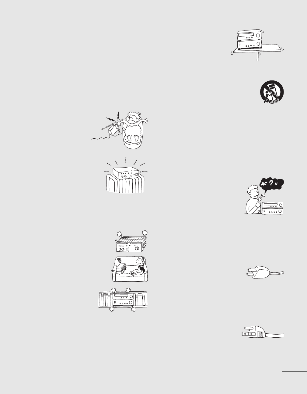
Ventilation
The slots and openings in the cabinet are provided for
necessary ventilation. To ensure reliable operation of the
appliance, and to protect it from overheating, these slots and
openings must never be blocked or covered.
– Never cover the slots and openings with
a cloth or other materials.
– Never block the slots and openings by
placing the appliance on a bed, sofa, rug
or other similar surface.
– Never place the appliance in a
confined space, such as a
bookcase, or built-in cabinet,
unless proper ventilation is
provided.
Accessories
Do not place the appliance on an
unstable cart, stand, tripod,
bracket, or table. The appliance
may fall, causing serious injury
to a child or an adult, and serious
damage to the appliance. Use
only a cart, stand, tripod, bracket, or table recommended by
Sony.
– An appliance and cart combination should be
moved with care. Quick stops, excessive force,
and uneven surfaces may cause the appliance
and cart combination to overturn.
S3125A
Wall or Ceiling Mounting
If your appliance can be mounted to a wall or ceiling, mount
it only as recommended by Sony.
USE
Power Source
This appliance should be operated only from the type of
power source indicated on the marking label. If you are not
sure of the type of electrical power supplied to your home,
consult your dealer or local power company.
For those appliances designed to
operate from battery power, or other
sources, refer to the operating
instructions.
Grounding or Polarization
This appliance is equipped with a polarized AC power cord
plug (a plug having one blade wider than the other), or with a
three-wire grounding type plug (a plug having a third pin for
grounding). Follow the instructions below:
- For the appliance with a polarized AC power
cord plug:
This plug will fit into the power outlet
only one way. This is a safety feature. If
you are unable to insert the plug fully
into the outlet, try reversing the plug. If the plug should still
fail to fit, contact your electrician to have a suitable outlet
installed. Do not defeat the safety purpose of the polarized
plug by forcing it in.
- For the appliance with a three-wire grounding
type AC plug:
This plug will only fit into a
grounding-type power outlet. This is a
safety feature. If you are unable to
insert the plug into the outlet, contact your electrician to have
a suitable outlet installed. Do not defeat the safety purpose, of
the grounding plug.
continued
US
3
Page 4
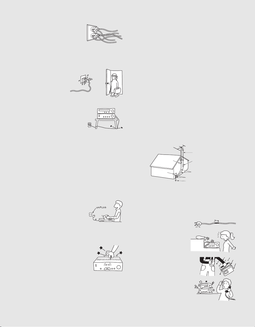
Overloading
Do not overload wall outlets,
extension cords or convenience
receptacles beyond their capacity,
since this can result in fire or electric
shock.
When not in use
Unplug the power cord of the appliance from the outlet when
left unused for a long period of time.
To disconnect the cord, pull
it out by grasping the plug.
Never pull the plug out by
the cord.
Power-Cord Protection
Route the power cord so that it is not
likely to be walked on or pinched by
items placed upon or against them,
paying particular attention to the
plugs, receptacles, and the point where
the cord exits from the appliance.
Attachments
Do not use attachments not recommended by Sony, as they
may cause hazards.
Lightning
For added protection for this appliance during a lightning
storm, or when it is left unattended and unused for long
periods of time, unplug it from the wall outlet and disconnect
the antenna or cable system. This will prevent damage to the
appliance due to lightning and powerline surges.
Cleaning
Unplug the appliance from the wall
outlet before cleaning or polishing it.
Do not use liquid cleaners or aerosol
cleaners. Use a cloth lightly dampened
with water for cleaning the exterior of
the appliance. Clean the appliance only
as recommended by Sony.
Object and Liquid Entry
Never push objects of any kind into the
appliance through openings as they may
touch dangerous voltage points or short
out parts that could result in a fire or
electric shock. Never spill liquid of any
kind on the appliance.
ANTENNAS
Outdoor Antenna Grounding
If an outdoor antenna or cable system is installed, follow the
precautions below.
An outdoor antenna system should not be located in the
vicinity of overhead power lines or other electric light or
power circuits, or where it can come in contact with such
power lines or circuits.
WHEN INSTALLING AN OUTDOOR ANTENNA
SYSTEM, EXTREME CARE SHOULD BE TAKEN TO
KEEP FROM CONTACTING SUCH POWER LINES OR
CIRCUITS AS CONTACT WITH THEM IS ALMOST
INVARIABLY FATAL.
Be sure the antenna system is grounded so as to provide some
protection against voltage surges and built-up static charges.
Section 810 of the National Electrical Code provides
information with respect to proper grounding of the mast and
supporting structure, grounding of the lead-in wire to an
antenna discharge unit, size of grounding conductors,
location of antenna-discharge unit, connection to grounding
electrodes, and requirements for the grounding electrode.
Antenna Grounding According to the National
Electrical Code
Antenna Lead-in Wire
Ground Clamp
Electric Service
Equipment
NEC -NATIONAL ELECTRICAL CODE
Antenna Discharge Unit
(NEC Section 810-20)
Grounding Conductors
(NEC Section 810-21)
Ground Clamps
Power Service Grounding
Electrode System
(NEC Art 250 Part H)
SERVICE
Damage Requiring Service
Unplug the appliance from the wall outlet and refer servicing
to qualified service personnel under the following conditions:
– When the power cord or plug is
damaged or frayed.
– If liquid has been spilled or
objects have fallen into the
appliance.
– If the appliance has been exposed to
rain or water.
– The appliance does not appear to
operate normally or exhibits a
marked change in performance. –
This indicates a need for service.
US
4
Page 5
– If the appliance does not operate
normally when following the operating
instructions, adjust only those controls
that are specified in the operating
instructions. Improper adjustment of
other controls may result in damage and
will often require extensive work by a
qualified technician to restore the
appliance to normal operation.
– If the appliance has been subject to
excessive shock by being dropped, or
the cabinet has been damaged.
Servicing
Do not attempt to service the
appliance yourself as opening or
removing covers may expose you
to dangerous voltage or other
hazards. Refer all servicing to
qualified service personnel.
Replacement parts
When replacement parts are required, be sure the service
technician has used replacement parts specified by Sony that
have the same characteristics as the original parts.
Unauthorized substitutions may result in fire, electric shock,
or other hazards.
Safety Check
Upon completion of any service or repairs to
the appliance, ask the service technician to
perform routine safety checks (as specified
by Sony) to determine that the appliance is
in safe operating condition.
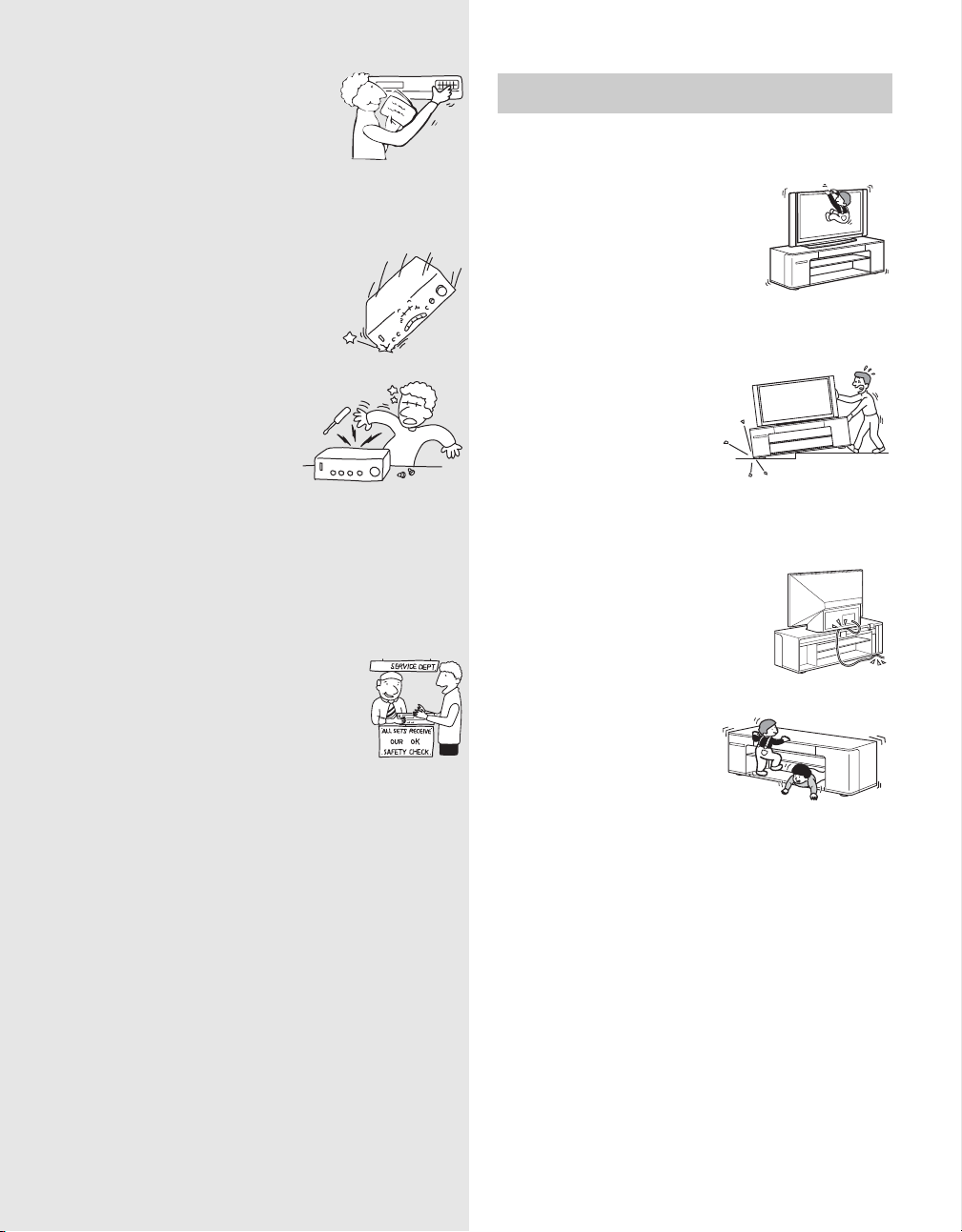
WARNING
Do not lean on or hang from the TV when
the TV is placed on the stand.
The TV may fall from the stand causing
an accident resulting in serious injury
or death.
Do not move the stand with the TV or other
equipment installed on it.
Be sure to remove the TV and
other equipment when moving
the stand. If you fail to do so, the
stand may lose balance and
topple over resulting in serious
injury.
Do not allow the AC power cord or the
connecting cable to be pinched between
the TV and the stand.
• The AC power cord or the connecting cable
may be damaged resulting in fire or electric
shock.
• When moving the stand, be careful not to
trap the AC power cord or the connecting
cable under the stand.
Do not climb on the stand.
The top front cover may become
loose and may fall from the
stand causing an accident
resulting in serious injury.
US
5
Page 6
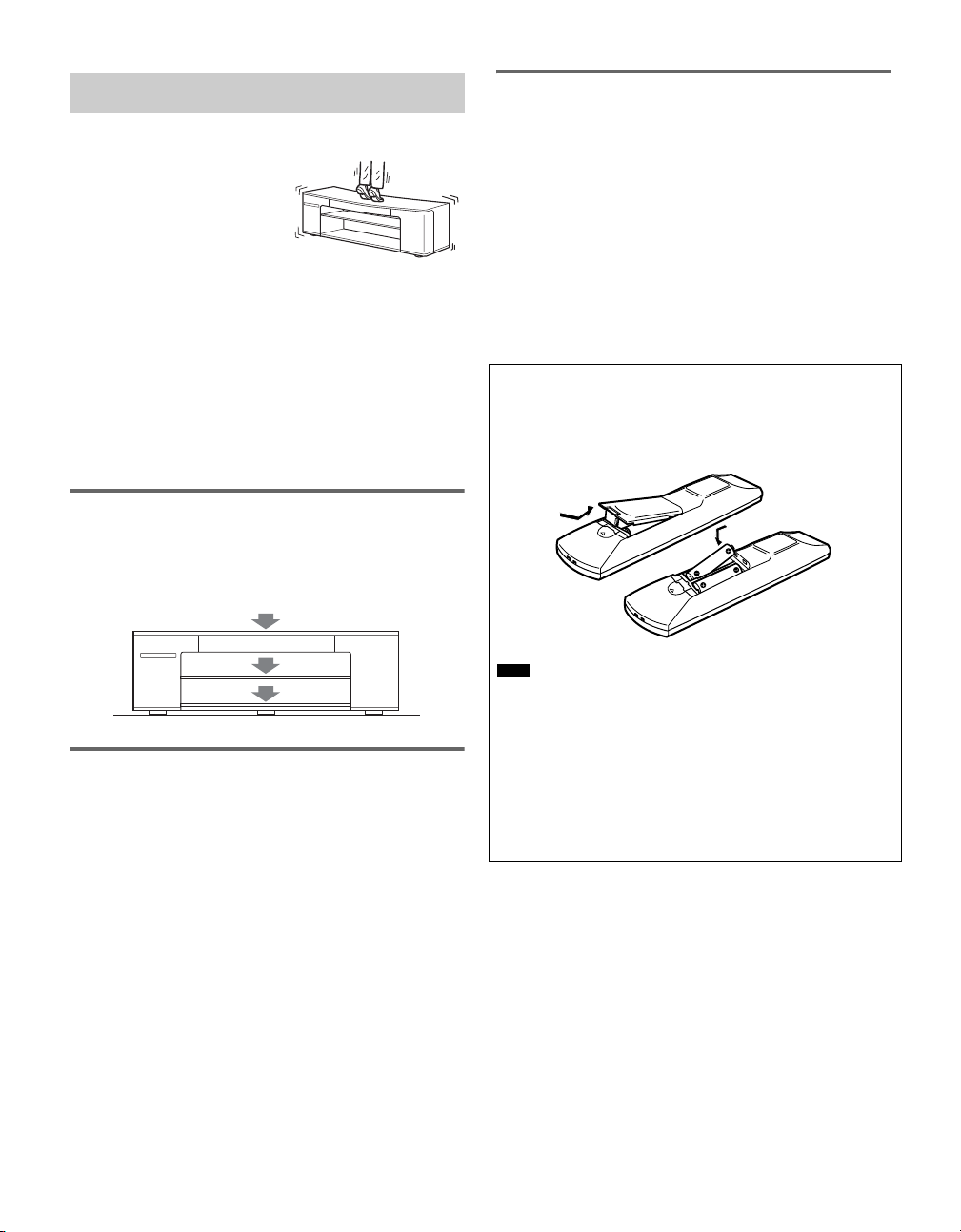
CAUTION
Do not step on the stand.
If you do so, you may fall from
the stand resulting in injury.
This stand is only for the specified TV.
• Do not place unspecified objects, such as a flower vase or pottery on
the stand.
• Do not make alterations to the stand.
Secure the TV to the stand.
If you fail to do so, the TV may fall or the stand may topple
over. This may cause injury. Following the instructions in this
manual, place the TV legs into the stopper and use the support
belt to prevent the TV from toppling over.
Note on load capacity
Do not place any equipment exceeding the specified
maximum weight on the stand, as indicated in the illustration
below. Otherwise, it may fall or break.
65 kg (143 lb 5 oz)
Notes on use
• Do n ot place any hot objects on the stand . If you do so, the stand may
discolor or distort.
• To keep the stand clean, occasionally wipe the stand gently with a
dry, soft cloth. Stubborn stains may be removed with a cloth slightly
dampened with diluted detergent, followed by a soft dry cloth. Do
not use any type of chemicals, such as thinner or benzine, as they
may damage the finish of the stand.
• When placing the top front cover on the floor after removing it from
the stand, cover the floor with a cloth, etc., beforehand to protect the
floor from damage.
Inserting batteries into the remote
You can control the system using the supplied remote. Insert
two size AA (R6) batteries by matching the + and − ends on
the batteries to the markings inside the compartment.
16 kg (35 lb 5 oz)
25 kg (55 lb 2 oz)
Notes on installation
• Be careful not to pinch your hand or fingers between the TV and the
stand.
• To prevent the stand from distorting, observe the following:
– Install the stand on a solid and flat surface.
– If you install the stand on a soft surface such as a mat, first lay a
board under the stand.
– Do not install the stand in a place subject to direct sunlight or near
a heater.
– Do not install the stand in a hot or humid place, or outdoors.
• Moving the stand requires four people or more. Move the stand only
after removing the TV. If you fail to do so, the TV may fall from the
stand resulting in serious injury. Do not hold the grille as it may
detach from the stand resulting in serious injury. Be careful not to
pinch your fingers when moving the stand.
US
6
Note
• Do not leave the remote in an extremely hot or humid place.
• Do not use a new battery with an old one.
• Do not drop any foreign object into the remote casing, particularly
when replacing the batteries.
• Do not expose the remote sensor to direct light from the sun or
lighting apparatus. Doing so may cause a malfunction.
• If you do not intend to use the remote for an extended period of time,
remove the batteries to avoid possible damage from battery leakage
and corrosion.
Page 7

Precautions
On safety
Should any solid object or liquid fall into the cabinet, unplug the
receiver and have it checked by qualified personnel before operating
it any further.
On power sources
• Before operating the receiver, check that the operating voltage is
identical to your local power supply. The operating voltage is
indicated on the nameplate at the rear of the receiver.
• The receiver is not disconnected from the AC power source as long
as it is connected to the wall outlet, even if the receiver itself has
been turned off.
• If you are not going to use the receiver for a long time, be sure to
disconnect the receiver from the wall outlet. To disconnect the AC
power cord, grasp the plug itself; never pull the cord.
• One blade of the plug is wider than the other for the purpose of
safety and will fit into the wall outlet only one way. If you are
unable to insert the plug fully into the outlet, contact your dealer.
• AC power cord must be changed only at the qualified service shop.
On heat buildup
Although the receiver heats up during operation, this is not a
malfunction. If you continuously use this receiver at a large volume,
the cabinet temperature of the top, side and bottom rises considerably.
To avoid burning yourself, do not touch the cabinet.
On placement
• Place the unit in a location with adequate ventilation to prevent heat
buildup and prolong the life of the unit.
• Do not place the unit near heat sources, or in a place subject to direct
sunlight, excessive dust or mechanical shock.
• Do not place anything on top of the cabinet that might block the
ventilation holes and cause malfunctions.
• Use caution when placing the unit on surfaces that have been
specially treated (with wax, oil, polish, etc.) as staining or
discoloration of the surface may result.
On operation
• Before connecting other components, be sure to turn off and unplug
the receiver.
• The sound fields memorized for each input and the preset stations
are retained for about a day even if you disconnect the AC power
cord.
On cleaning
Clean the cabinet, panel and controls with a soft cloth slightly
moistened with a mild detergent solution. Do not use any type of
abrasive pad, scouring powder or solvent such as alcohol or benzine.
If you have any question or problem concerning your receiver, please
consult your nearest Sony dealer.
US
7
Page 8

Table of Contents
WARNING.................................................................5
CAUTION..................................................................6
Precautions .................................................................7
Controlling the connected
components
Programming the remote for TV operation
(Sony TV only) ....................................................9
(Input SYNC)
Programming the remote.......................................... 10
Controlling the connected components....................12
Settings and Adjustments
Using the AMP menu............................................... 14
Setting up the speakers .............................................14
Enjoying the sound at low volume...........................15
(AUDIO DRC)
Enjoying Multiplex Broadcast Sound ...................... 15
(DUAL MONO)
Adjusting the Delay Between the Picture and
Sound..................................................................16
(A/V SYNC)
Changing the Brightness of the Front Panel
Display ............................................................... 16
(DIMMER)
Selecting the sound field ..........................................17
Other operations
Listening to the radio................................................19
Using the Sleep Timer..............................................20
Using optional speakers in 5.1CH
mode
Positioning optional speakers...................................21
Connecting the speakers...........................................21
Setting up the surround speakers..............................22
Selecting the sound field ..........................................23
Additional Information
Troubleshooting........................................................ 25
Specifications ...........................................................27
Glossary....................................................................28
Index to Parts and Controls ...................................... 29
US
8
Page 9
Controlling the connected components
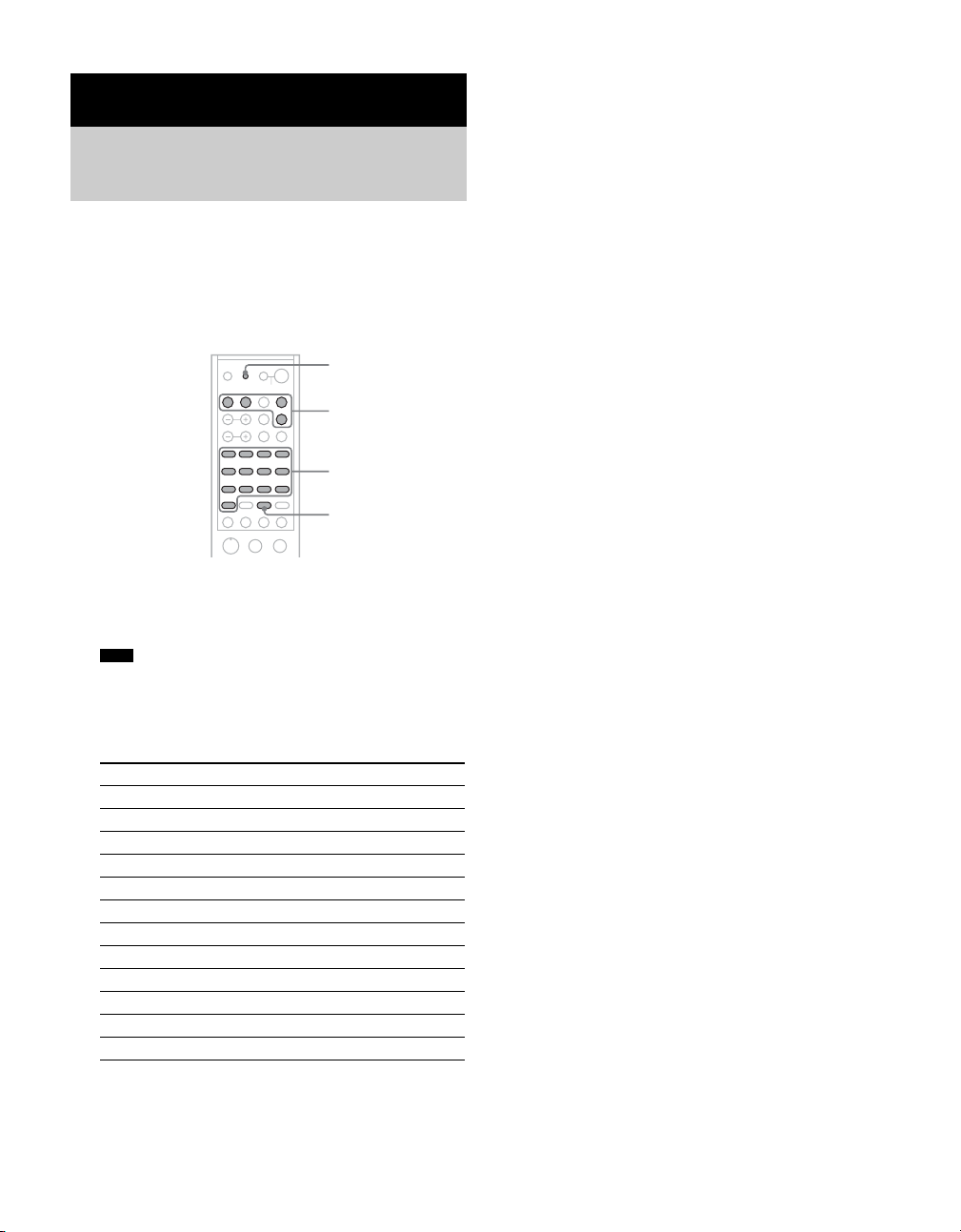
Programming the remote for TV operation (Sony TV only)
(Input SYNC)
If you connect your TV by jacks other than VIDEO IN 1 or
HD/DVD IN 5 (see the supplied “Quick Setup Guide”),
follow the steps below to program the remote. The TV input
will be selected automatically (Input SYNC).
RM SETUP
Input buttons
Numeric buttons, etc.
ENTERCLEAR
-
Mm.
H
>
X
x
ENTER
1 Press the input button for the component you want
to change while holding down RM SETUP.
The indicator lights up.
Note
• Press the RM SETUP button using a pointed object.
2 See the table below for the remote button
corresponding to the TV input jack you have
connected to, and press the button.
TV input jack* Remote Button
VIDEO 1 1
VIDEO 2 2
VIDEO 3 3
VIDEO 4 4
VIDEO 5 5
VIDEO 6 6
VIDEO 7 7
VIDEO 8 8
COMPONENT 1 9
COMPONENT 2 AUDIO
COMPONENT 3 SUBTITLE
COMPONENT 4 ANGLE
* TV input jack name may differ depending on your TV model.
3 Press ENTER.
The indicator slowly flashes twice and the remote
automatically exits the programming mode.
To disable this function
Press ENTER while holding down 0 in step 2. The TV input
will not be selected automatically even if you press the input
buttons.
US
9
Page 10
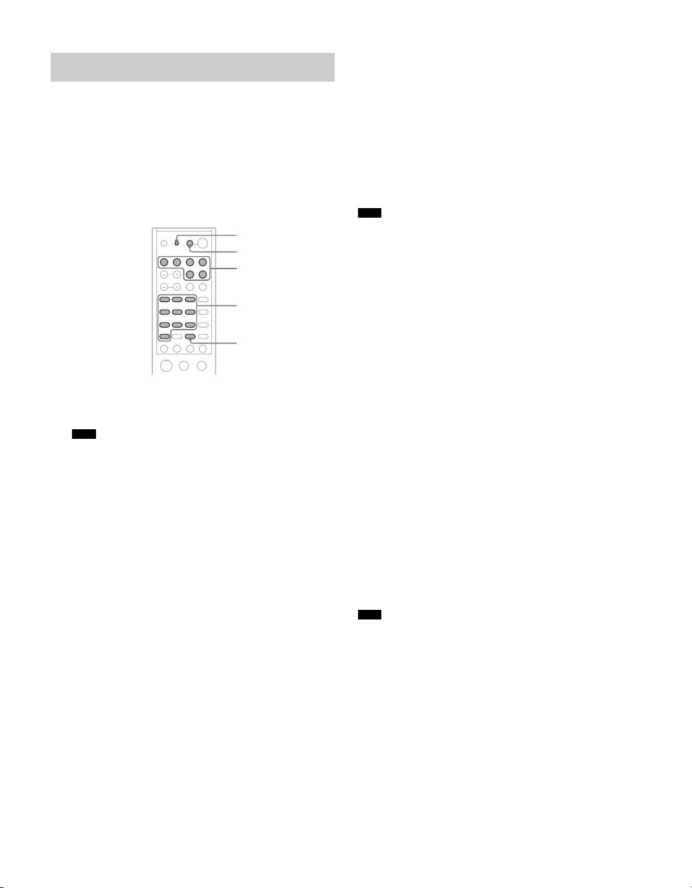
Programming the remote
You can program the remote to control non-Sony components
by changing the code. Once the control signals have been
memorized, you can use those components as part of your
system.
Furthermore, you can also program the remote for Sony
components that the remote is unable to control. Note that the
remote can only control components that accept infrared
wireless control signals.
RM SETUP
AV ?/1
Input buttons
Numeric buttons
ENTERCLEAR
-
Mm.
H
>
X
x
ENTER
1 Press AV ?/1 while holding down RM SETUP.
The indicator lights up.
Note
• Press the RM SETUP button using a pointed object.
2 Press the input button for the component you want
to control.
For example, if you are going to control a DVD player,
press DVD.
3 Press the numeric buttons to enter the numeric
code (or one of the codes if more than one code
exists) corresponding to the component and the
maker of the component you want to control.
See the tables on pages 11–12 for information on the
numeric code(s) corresponding to the component and the
maker of the component (the first digit and the last two
digits of the numeric code correspond to the category and
the maker’s code respectively).
4 Press ENTER.
Once the numeric code has been verified, the indicator
slowly flashes twice and the remote automatically exits
the programming mode.
5 Repeat steps 1 to 4 to control other components.
To cancel programming
Press RM SETUP during any step. The remote automatically
exits the programming mode.
To activate the input after programming
Press the programmed button to activate the input you want.
If programming is unsuccessful, check the
following:
• If the indicator does not light up in step 1, the batteries are
weak. Replace both batteries.
• If the indicator flashes 4 times in quick succession while
entering the numeric code, an error has occurred. Start
again from step 1.
Note
• The indicator turns off while a valid button is pressed.
• In step 2, if several input buttons are pressed, only the last pressed
button is valid.
• In step 2, if you press TV ?/1, only TV VOL +/– , TV CH +/–, TV/
VIDEO and WIDE buttons are reprogrammed.
• In step 3, if an input button is pressed, the new input is selected and
the programming procedure returns to the beginning of step 3.
• For the numeric codes, only the first three numbers entered are
valid.
To clear the memory of the remote
To clear all programmes, do the following to reset the remote
to factory settings.
Press VOLUME –, ?/1 and AV ?/1 at the same time.
The indicator flashes 3 times, then goes off.
The numeric codes corresponding to the
component and the maker of the
component
Use the numeric codes in the tables below to control nonSony components and also Sony components that the remote
is normally unable to control. Since the remote signal that a
component accepts differs depending on the model and year
of the component, more than one numeric code may be
assigned to a component. If you fail to program your remote
using one of the codes, try using other codes.
Note
• The numeric codes are based on the latest information available for
each brand. There is a chance, however, that your component will
not respond to some or all of the codes.
• All of the input buttons on this remote may not be available when
used with your particular component.
10
US
Page 11

To control a CD player
Maker Code(s)
SONY 101, 102, 103
DENON 104, 123
JVC 105, 106, 107
KENWOOD 108, 109, 110
MARANTZ 116
ONKYO 112, 113, 114
PIONEER 117
YAMAHA 120, 121, 122
To control a DAT deck
Maker Code(s)
SONY 203
PIONEER 219
To control an MD deck
Maker Code(s)
SONY 301
To control a tape deck
Maker Code(s)
SONY 201, 202
DENON 204, 205
NAKAMICHI 210
PIONEER 213, 214
YAMAHA 217, 218
To control a VCR
Maker Code(s)
SONY 701, 702, 703, 704, 705, 706
AKAI 707, 708, 709, 759
EMERSON 711, 712, 713, 714, 715, 716, 750
FISHER 717, 718, 719, 720
GENERAL ELECTRIC 721, 722, 730
GOLDSTAR/LG 723, 753
HITACHI 722, 725, 729, 741
JVC 726, 727, 728, 736
MAGNAVOX 730, 731, 738
MITSUBISHI/MGA 732, 733, 734, 735
PANASONIC 729, 730, 737, 738, 739, 740
PHILIPS 729, 730, 731
PIONEER 729
RCA/PROSCAN 722, 729, 730, 731, 741, 747
SAMSUNG 742, 743, 744, 745
SANYO 717, 720, 746
SHARP 748, 749
TOSHIBA 747, 755, 756
ZENITH 754
To control a DVD player
Maker Code(s)
SONY 401, 402, 403
PANASONIC 406, 408
PHILIPS 407
PIONEER 409
TOSHIBA 404
DENON 405
11
US
Page 12

To control a TV
Maker Code(s)
SONY 501
DAEWOO 504, 505, 506, 515, 544
FISHER 508
GOLDSTAR/LG 503, 511, 512, 515, 534, 544
HITACHI 513, 514, 515, 544
JVC 516
MAGNAVOX 503, 518, 544
MITSUBISHI/MGA 503, 519, 544
NEC 503, 520, 544
PANASONIC 509, 524
PHILIPS 515, 518
PIONEER 509, 525, 526
RCA/PROSCAN 510, 527, 529, 544
SAMSUNG 503, 515, 531, 532, 533, 534, 544
SANYO 508, 545, 547
SHARP 535
THOMSON 530, 537, 547
TOSHIBA 535, 541
ZENITH 542, 543
To control a satellite tuner or cable box
Maker Code(s)
SONY 801, 802, 803, 804, 821, 822,
823, 824, 825
JERROLD/G.I. 806, 807, 808, 809, 810, 811,
812, 813, 814
PANASONIC 818
RCA 805, 819
S. ATLANTA 815, 816, 817
To control a tuner
Maker Code(s)
SONY 001, 004, 005
Controlling the connected components
You can control connected components with the remote of
this system.
1
qk
2
qj
ENTERCLEAR
-
qh
qg
Mm.
H
>
X
x
qf
qd
qs
*
qa
O
3
4
5
6
7
8
9
0
*
To control a hard disc recorder
Maker Code(s)
SONY 307, 308, 309
To control a blu-ray disc recorder
Maker Code(s)
SONY 310, 311, 312
US
12
* The H, TV VOL+, and TV CH+ buttons have a tactile dot. Use
the tactile dot as a reference when operating the system and other
audio/video components.
Page 13

Common operations
Remote Button Function
1 AV \/1 Turns the audio and video
1 SYSTEM STANDBY (Press
AV \/1 and \/1 at the same
time)
7 AV MENU Displays menu.
components on or off.
Turns off this system and other
Sony audio/video components.
To control the DVD recorder/DVD player
Remote Button Function
2 AUDIO Changes the sound to Multiplex
3 SUBTITLE Changes the subtitles.
4 ANGLE Selects viewing angle or
5 ./> Skips chapters.
6 Play mode buttons H (playback)/X (pause)/x
8 DISPLAY Selects information displayed on
qs RETURNO/EXIT Returns to the previous menu.
qd C/X/x/c/ENTER Selects a menu item and enters
qf TOP MENU Displays DVD title.
qg m/M Searches chapters in a forward
qh CLEAR Clears a mistake when you press
qk DISC SKIP Skips discs (multi-disc changer
or Bilingual Sound.
changes the angles.
(stop)
the TV screen.
the selection.
or backward direction.
incorrect numeric buttons or
returns to continuous playback.
only).
To control the TV
Remote Button Function
1 TV \/1 Turns the TV on or off.
2 AUDIO Changes the sound to Multiplex,
8 DISPLAY Selects information displayed on
qa TV/VIDEO Selects input signal: TV input or
qa TV CH +/– Selects preset TV channels.
qa TV VOL +/– Adjusts the volume of the TV.
qa WIDE Selects the wide picture mode.
qj Numeric buttons Selects channel numbers.
qk CH +/– Selects preset channels.
Bilingual or Multi channel TV
Sound.
the TV screen.
video input.
To control the SAT
Remote Button Function
0 JUMP Toggles between the previous
and the current channels.
qs EXIT Exits the menu.
qd C/X/x/c/ENTER Selects a menu item and enters
the selection.
qf GUIDE Displays guide menu.
qj Numeric buttons Selects channel numbers.
qk CH +/– Selects preset channels.
To control the VCR
Remote Button Function
2 AUDIO Changes the sound to Multiplex
or Bilingual Sound.
6 Play mode buttons H (playback)/X (pause)/
x (stop)
8 DISPLAY Selects information displaye d on
the TV screen.
9 ANT Selects output signal from the
antenna terminal: TV signal or
VCR program.
qd C/X/x/c/ENTER Selects a menu item and enters
the selection.
qg m/M Fast forwards or rewinds.
qk CH +/– Selects preset channels.
To control the audio components
Remote Button Function
5 ./> Skips tracks.
6 Play mode buttons H (playback)/X (pause)/
x (stop)
qg m/M Searches tracks in a forward or
backward direction.
qj Numeric buttons Selects track numbers.
0/10 selects track 10.
qk DISC SKIP Skips discs (multi-disc changer
only).
Note
• The above explanations are intended to serve as an example only.
Depending on the component, the above operations may not be
possible, or may operate differently than described.
• Before you press C/X/x/c to operate this system, press AMP
MENU first; to operate other components, press input buttons and
AV MENU or TOP MENU/GUIDE first.
13
US
Page 14

Settings and Adjustments
Using the AMP menu
In FRONT mode, you can set the following items with AMP
MENU on the remote.
The default settings are underlined.
Setting up the speakers
You can adjust the level of the center speaker and the
subwoofer. This setting is applied to all sound fields.
AMP MENU
LEVEL
CUSTOMIZE
CEN LEVEL
(center speaker
level)
SW LEVEL
(subwoofer level)
AUDIO DRC
DUAL MONO
A/V SYNC SYNC OFF
DIMMER
-6 dB – +6 dB (0 dB)
-6 dB – +6 dB (0 dB
DRC OFF
DRC STD
DRC MAX
MAIN
SUB
MAIN+SUB
MAIN/SUB
SYNC ON
DIMMER OFF
DIMMER ON
1 Press AMP MENU to turn on the AMP menu.
2 Press C/X/x/c repeatedly to select the item and the
setting.
3 Press AMP MENU to turn off the AMP menu.
The following pages show details for each setting.
AMP MENU
ENTERCLEAR
-
>
)
X/x/c
ENTER
Mm.
H
O
X
x
1 Start playing a source encoded with multi channel
surround effects (DVD, etc.).
2 Press AMP MENU.
3 Press x/X repeatedly until “LEVEL” appears, then
press ENTER or c.
4 Press x/X repeatedly to select “CEN LEVEL” or
“SW LEVEL”, then press ENTER or c.
5 While monitoring the sound, press x/X repeatedly
to select the setting you want.
• CEN LEVEL (center speaker level)
• SW LEVEL (subwoofer level)
Default setting: 0 dB
You can adjust from -6 dB to +6 dB in 1 dB steps.
6 Press ENTER or AMP MENU.
The AMP menu turns off.
14
US
Page 15

Enjoying the sound at low volume
Enjoying Multiplex Broadcast
(AUDIO DRC)
Narrows the dynamic range of the sound track. Useful for
watching movies at low volume late at night.
AMP MENU
ENTERCLEAR
-
>
Mm.
X
x
H
X/x/c
ENTER
O
1 Press AMP MENU.
2 Press x/X repeatedly until “CUSTOMIZE” appears,
then press ENTER or c.
3 Press x/X repeatedly until “AUDIO DRC” appears,
then press ENTER or c.
4 Press x/X to select the setting.
• DRC OFF : no compression of dynamic range.
• DRC STD : reproduces the sound track with the kind of
dynamic range that the recording engineer intended.
• DRC MAX : compresses dynamic range fully.
5 Press ENTER or AMP MENU.
The AMP menu turns off.
Note
• AUDIO DRC only applies to Dolby Digital sources.
Sound
(DUAL MONO)
You can enjoy multiplex broadcast sound when the system
receives an AC-3 multiplex broadcast signal.
Note
• To receive AC-3 signal, you need to connect a digital satellite tuner
to the system with an optical cable or coaxial cable, and set the
digital output mode of the digital satellite tuner to AC-3.
AMP MENU
ENTERCLEAR
-
>
Mm.
X
x
H
X/x/c
ENTER
O
1 Press AMP MENU.
2 Press x/X repeatedly until “CUSTOMIZE” appears,
then press ENTER or c.
3 Press x/X repeatedly until “DUAL MONO”
appears, then press ENTER or c.
4 Press x/X to select the sound you want.
• MAIN: plays back only the main channel.
• SUB: plays back only the sub channel.
• MAIN+SUB: mixed playback of the main and sub
channels.
• MAIN/SUB: main sound is output from the left speaker
and sub sound is output from the right speaker.
5 Press ENTER or AMP MENU.
The AMP menu turns off.
15
US
Page 16

Adjusting the Delay Between the
Changing the Brightness of the
Picture and Sound
(A/V SYNC)
If picture and sound are not synchronized, you can adjust the
delay between picture and sound.
AMP MENU
ENTERCLEAR
-
>
Mm.
X
x
H
X/x/c
ENTER
O
1 Press AMP MENU.
2 Press x/X repeatedly until “CUSTOMIZE” appears,
then press ENTER or c.
3 Press X/x repeatedly until “A/V SYNC” appears,
then press ENTER or c.
4 Press X/x to select the setting.
• SYNC OFF: does not adjust.
• SYNC ON: adjusts the difference between picture and
sound.
5 Press ENTER or AMP MENU.
The AMP menu turns off.
Note
• Depending on the input stream, this function may not be effective.
Front Panel Display
(DIMMER)
The brightness of the front panel display can be set to one of
2 levels.
AMP MENU
ENTERCLEAR
-
>
Mm.
X
x
H
X/x/c
ENTER
O
1 Press AMP MENU.
2 Press x/X repeatedly until “CUSTOMIZE” appears,
then press ENTER or c.
3 Press X/x repeatedly until “DIMMER” appears,
then press ENTER or c.
4 Press X/x to select the brightness of the front
panel display.
• DIMMER OFF: bright lighting.
• DIMMER ON: low lighting. Turns off the lighting
when the power is off.
5 Press ENTER or AMP MENU.
The AMP menu turns off.
16
US
Page 17

Selecting the sound field
Sound field indicator
?/1
This system can create 5.1 channel surround sound. You can
take advantage of this front surround sound simply by
selecting one of system's preprogrammed sound fields. They
bring the exciting and powerful sound of movie theaters into
your home.
SOUND
FIELD +/–
ENTERCLEAR
-
>
Mm.
X
x
H
O
About S-Force PRO Front Surround
Sony’s long-term involvement in surround technology (and
the vast amounts of acoustic data accumulated as a result) has
led to the development of all-new processing method and
advanced DSP to handle this task effectively, which we call
S-Force PRO Front Surround. Compared with previous front
surround technologies, S-Force PRO Front Surround
reproduces a more convincing sense of distance and space,
resulting in a true surround sound experience without the
need for rear speakers.
Automatic outputting of the original
sound
x AUTO
This mode selects the sound field automatically, according to
the type of audio signal being input.
Enjoying the Front Surround Sound
System
x FRONT SURROUND
You can enjoy surround sound in FRONT SURROUND area
as illustrated below.
TV
Theatre Stand
Enjoying Front Surround Sound Using
Sound Field
Press SOUND FIELD +/–.
The present sound field appears.
Press SOUND FIELD +/– repeatedly until the sound field
you want appears. The selected sound field indicator on the
front panel lights up*.
* When you press SOUND FIELD +/– and the selected field is
AUTO, AUTO and the selected sound field indicator (FRONT
SURROUND or 2CH STEREO) light up.
Available sound fields
Sound field Display
AUTO AUTO MODE
FRONT SURROUND FRONT SURR
2CH STEREO 2CH STEREO
NEWS NEWS
* Using S-Force PRO Front Surround technology.
*
3 m (10 ft)
FRONT SURROUND area
Outputting 2 channel sources
x 2CH STEREO
This mode outputs 2 channel sound regardless of the audio
signal type being input.
continued
17
US
Page 18

Outputting sound sources from TV
x NEWS
This mode clearly reproduces human voice in TV programs,
such as news programs or dramas.
Tip
• The system memorizes the last sound field selected for each input.
In TUNER function mode, the same sound field is memorized for
both FM and AM.
18
US
Page 19

Other operations
Listening to the radio
TUNER/BAND
6 Press ENTER.
The station is stored.
TUNED ST
7 Repeat 1 to 6 to store other stations.
To change the preset number
Restart from Step 1.
FM MODE
TUNER MENU
CLEAR
TUNING +/–
C/X/x/c
ENTER
Mm.
H
O
ENTERCLEAR
-
PRESET +/–
>
X
x
VOLUME +/–
DISPLAY
Presetting radio stations
You can preset 20 FM stations, and 10 AM stations. Before
tuning, make sure to turn down the volume to minimum.
1 Press TUNER/BAND repeatedly until the band you
want appears.
2 Press and hold TUNING + or – until the auto
scanning starts.
Scanning stops when the system tunes in a station.
“TUNED” and “ST” (for stereo program) appear.
TUNED ST
3 Press TUNER MENU repeatedly until “Memory?”
appears.
4 Press ENTER.
A preset number appears.
Listening to the radio
Preset radio stations in the system’s memory first (see
“Presetting radio stations” (page 19)).
1 Press TUNER/BAND repeatedly until “FM” or “AM”
appears.
The last received station is tuned in.
TUNED ST
2 Press PRESET + or – repeatedly to select the
preset station you want.
Each time you press the button, the system tunes in one
preset station.
3 Adjust the volume by pressing VOLUME +/–.
To turn off the radio
Press "/1.
To listen to non-preset radio stations
Use manual or automatic tuning in Step 2.
For manual tuning, press TUNING + or – repeatedly.
For automatic tuning, press and hold TUNING + or –. Press
TUNING + or – to stop the automatic tuning.
Tip
• If an FM program is noisy, press FM MODE so that “MONO”
appears. There will be no stereo effect, but the reception will
improve. Press the button again to restore the stereo effect.
• To improve reception, reorient the supplied antennas.
TUNED ST
5 Press X/x to select the preset number you want.
TUNED ST
continued
19
US
Page 20

Naming preset stations
You can enter a name for preset station. The name (for
example, “XYZ”) appears when the station is selected.
Note that no more than one name can be entered for each
preset station.
1 Press TUNER/BAND repeatedly until “FM” or “AM”
appears.
The last station you received is tuned in.
2 Press PRESET + or – repeatedly to select the
preset station you want to create an index name
for.
3 Press TUNER MENU.
4 Press C/X/x/c repeatedly until “Name In?”
appears.
5 Press ENTER.
6 Create a name by using the cursor buttons.
Press X/x to select a character, then press c to move the
cursor to the next position.
Letters, numbers, and other symbols can be input for a
radio station name.
If you make a mistake
Press C/c repeatedly until the character to be changed
flashes, then press X/x to select the desired character.
To erase the character, press C/c repeatedly until the
character to be erased flashes, then press CLEAR.
7 Press ENTER.
The station name is stored.
Tip
• You can check the frequency by pressing DISPLAY repeatedly.
To change the AM tuning interval
The AM tuning interval can be set to either 10 kHz or 9 kHz.
To change the AM tuning interval, first tune in any AM
station, then turn off the system by pressing "/1 on the
system. While holding down INPUT SELECTOR, press "/1
on the system to turn on the power. If you change the interval,
AM preset stations will be erased.
To reset the interval, repeat the same procedure.
Using the Sleep Timer
You can set the system to turn off at a preset time, so you can
fall asleep listening to music. You can preset the time in 10
minutes decrements.
SLEEP
ENTERCLEAR
-
>
Mm.
X
x
H
O
Press SLEEP.
Each time you press this button, the minutes display (the
remaining time) changes as follows:
SLEEP 90M t SLEEP 80M t SLEEP 70M
Rr
SLEEP OFF T SLEEP 10M ..... SLEEP 60M
To check the remaining time
Press SLEEP once.
To change the remaining time
Press SLEEP repeatedly to select the desired time.
To cancel the Sleep Timer function
Press SLEEP repeatedly until “SLEEP OFF” appears.
Note
• This function is only for this system, not for the connected TV or
other components.
20
US
Page 21

Using optional speakers in 5.1CH mode
Connecting the speakers
Positioning optional speakers
You can connect your optional speakers to this system as
surround speakers.
The optional speakers should be placed up to 5.0 m (16 ft)
from the listening position.
Place the optional speakers as illustrated below.
TV
Theatre Stand
5.0 m
(16 ft)
Surround speakers
Connecting the speakers
SPEAKERS
-
+
L
R
+
L
R
-
Switching from FRONT mode to 5.1CH
mode
1 Slide the 5.1CH/FRONT mode switch on the rear
panel.
MODE
5.1CH
FRONT
2 Turn off the power and turn on again. “5.1CH
MODE” appears.
To switch from 5.1CH mode to FRONT
mode
1 Slide the 5.1CH/FRONT mode switch on the rear
panel.
2 Turn off the power and turn on again. “FRONT
MODE” appears.
21
US
Page 22

Setting up the surround speakers
To obtain the best possible surround sound, set for the size of
the speakers you have connected and their distance from your
listening position.
Default settings are underlined.
AMP MENU
ENTERCLEAR
-
>
Mm.
X
x
H
X/x/c
ENTER
O
1 Press AMP MENU.
2 Press X/x repeatedly until “SP SETUP” or
“LEVEL” appears, then press ENTER or c.
3 Select an item using X/x, then press ENTER or c.
4 Select a setting using X/x, then press ENTER.
The setting is selected and setup is complete.
LEVEL menu parameters
You can adjust the level of the speakers. Use the test tone for
easy adjustment (see “To set the speaker level by using the
test tone” on page 23).
x TEST TONE
[T.TONE OFF] Emits no test tone.
[T.TONE ON] Emits test tone from the speakers in turn.
x FL LEVEL (front left speaker level)
Default setting: 0 dB
You can set in 1 dB increments from -6 dB to 0 dB.
x CEN LEVEL (center speaker level)
Default setting: 0 dB
You can set in 1 dB increments from -6 dB to +6 dB.
x FR LEVEL (front right speaker level)
Default setting: 0 dB
You can set in 1 dB increments from -6 dB to 0 dB.
x SR LEVEL (surround right speaker level)
Default setting: 0 dB
You can set in 1 dB increments from -6 dB to +6 dB.
x SL LEVEL (surround left speaker level)
Default setting: 0 dB
You can set in 1 dB increments from -6 dB to +6 dB.
x SW LEVEL (subwoofer level)
Default setting: 0 dB
You can set in 1 dB increments from -6 dB to +6 dB.
SP SETUP menu parameters
x SURR SP (surround speakers)
[SURR YES] Select this if surround speakers are connected.
[SURR NO] Select this if no surround speakers are connected.
x FRONT DIST (front speaker distance)
Default setting: 3.0 meters (10 ft)
You can set in 0.2 meter (1 ft) increments from 1.0 to 7.0
meters (4 to 23 ft).
x SURR DIST (surround speaker distance)
Default setting: 3.0 meters (10 ft)
You can set in 0.2 meter (1 ft) increments from 0.0 to 7.0
meters (0 to 23 ft).
Note
• The value you can set for SURR DIST differs depending on the
value you have set for FRONT DIST.
US
22
Page 23

To set the speaker level by using the test
tone
1 Press AMP MENU.
2 Press x/X repeatedly until “LEVEL” appears, then
press ENTER or c.
3 Press x/X to select “TEST TONE”, and press
ENTER or c.
4 Press x/X to select “T.TONE ON”.
The speakers emit the test tone in turn.
5 Press C to return, and then press x/X to select a
speaker:
“FL LEVEL” (front left speaker level)
“CEN LEVEL” (center speaker level)
“FR LEVEL” (front right speaker level)
“SR LEVEL” (surround right speaker level)
“SL LEVEL” (surround left speaker level)
“SW LEVEL” (subwoofer level).
6 Press ENTER or c.
The selected speaker emits the test tone.
7 From your listening position, adjust the speaker
level by pressing x/X.
8 Repeat steps 5 to 7 to adjust the other speaker
levels.
9 When you finish adjusting levels, press C to return.
10 Press x/X to select “TEST TONE”, and press
ENTER or c.
11 Press x/X to select “T.TONE OFF”, and press AMP
MENU to turn off the AMP menu.
Selecting the sound field
You can take advantage of surround sound simply by
selecting one of system’s preprogrammed sound fields. They
bring the exciting and powerful sound of movie theaters into
your home.
SOUND
FIELD +/–
ENTERCLEAR
-
>
Mm.
X
x
H
O
Press SOUND FIELD +/–.
The present sound field appears.
Press SOUND FIELD +/– repeatedly until the sound field
you want appears. The selected sound field indicator on the
front panel lights up.
All sound fields in 5.1CH mode
Sound field Display
AUTO FORMAT DIRECT AUTO A.F.D. AUTO
Dolby Pro Logic PRO LOGIC
Dolby Pro Logic II MOVIE PLII MOVIE
Dolby Pro Logic II MUSIC PLII MUSIC
2CH STEREO 2CH STEREO
NEWS NEWS
MULTI ST. MULTI ST.
continued
23
US
Page 24

Automatic outputting of the original
sound
x AUTO FORMAT DIRECT AUTO
The auto decoding function automatically detects the type of
audio signal being input (Dolby Digital, DTS, or standard 2
channel stereo) and performs the proper decoding if
necessary. This mode presents the sound as it was recorded/
encoded, without adding any effects (e.g. reverberation).
However, if there are no low frequency sign als (Dolby Digital
LFE, etc.), it will generate a low frequency signal for output
to the subwoofer.
Outputting 2 channel sources like CDs
by 5.1channel
x Dolby Pro Logic
Dolby Pro Logic produces five output channels from 2
channel sources. This mode performs Pro Logic decoding to
the input signal and output to front, center, and surround
speakers. Meanwhile, the surround channel becomes
monaural.
x Dolby Pro Logic II MOVIE/MUSIC
Dolby Pro Logic II produces five full-bandwidth output
channels from 2 channel sources. This is done using an
advanced, high-purity matrix surround decoder that extracts
the spatial properties of the original recording without adding
any new sounds or tonal colorations.
Note
• When the input signal is multi channel source, Dolby Pro Logic and
Dolby Pro Logic II MOVIE/MUSIC are canceled and the multi
channel source is output directly.
• When the bilingual broadcast sound is input, Dolby Pro Logic and
Dolby Pro Logic II MOVIE/MUSIC are not effective.
Outputting 2 channel sources from the
front, center, and surround speakers
x MULTI ST.
This mode outputs 2 channel sources from the front, center,
and surround speakers simultaneously. The sound that is
output from the surround speakers is same as the sound that is
output from the front speakers.
Tip
• The system memorizes the last sound field selected for each input.
In TUNER function mode, the same sound field is memorized for
both FM and AM.
Using only the front speaker and
subwoofer
x 2CH STEREO
This mode outputs 2 channel sound regardless of the audio
signal type being input.
Outputting sound sources from TV
x NEWS
This mode clearly reproduces human voice in TV programs,
such as news programs or dramas.
US
24
Page 25

Additional Information
Troubleshooting
If you experience any of the following difficulties while using
the system, use this troubleshooting guide to help remedy the
problem before requesting repairs. Should any problem
persist, consult your nearest Sony dealer.
General
The power is not turned on.
• Check that the AC power cord is connected securely.
If “PROTECT” and “UNPLUG” appears alternately.
Immediately unplug the AC power cord and check the
following items.
• Check that the speaker cords of the optional speakers are
not short-circuited.
• Is anything blocking the ventilation holes of the system?
After checking the above items and fixing any problems,
connect the AC power cord again and turn on the system.
If the cause of the problem cannot be found even after
checking all the above items, consult your nearest Sony
dealer.
Dolby Digital or DTS multi channel sound is not
reproduced.
• Check that the playing DVD, etc, is recorded in Dolby
Digital or DTS format.
• When connecting the DVD player, etc, to the digital input
jacks of this system, check that audio setting (settings for
the audio output) of the connected component.
• Check that the DVD player selects the correct settings.
(Check the sound from DVD menu.)
The surround effect cannot be obtained.
• Press SOUND FIELD +/–, make sure the sound field
function is on.
• Depending on the digital signal, the sound field may not
function.
There is no sound from one of the front speakers.
• Check that the component is connected correctly to the
audio input jacks for that component.
• Check that the cords are fully inserted into the jacks on
both the component and this system.
The left and right sounds are unbalanced or reversed.
• Check that the components are connected correctly and
securely.
• Adjust balance parameters in the LEVEL menu.
There is no sound from the center speaker.
• Press SOUND FIELD +/– and check the selected sound
field.
• Depending on the source, the sound effect from the center
speaker may be less noticeable.
• Adjust the level of the speaker.
No sound or only a very low-level sound is heard from the
surround speakers in FRONT mode.
• Press SOUND FIELD +/– and check the selected sound
field.
• Check that the 5.1CH/FRONT mode switch is switched
over FRONT mode.
• Turn off the system power, and turn it on after sliding the
5.1CH/FRONT mode switch.
• Depending on the source, the sound effect of the surround
speakers may be less noticeable.
No sound is heard from the surround speakers when
connected in 5.1CH mode.
• Check the settings of the surround speakers.
• Press SOUND FIELD +/– and check the selected sound
field.
• Check that the 5.1CH/FRONT mode switch is switched
over 5.1CH mode.
• Turn off the system power, and turn it on after sliding the
5.1CH/FRONT mode switch.
• Depending on the source, the sound effect of the surround
speakers may be less noticeable.
Connected components
There is no sound or only a very low-level sound no matter
which component is selected.
• Check that the speakers and components are connected
correctly and securely.
• Check that both this system and the selected component
are turned on.
• Check that the volume is not set to the minimum level.
• Press MUTING to cancel the muting function.
There is no sound from the selected component
• Check that the component is connected correctly to the
audio input jacks for that component.
• Check that the cords are fully inserted into the jacks on
both the component and this system.
• Check that the component is selected correctly.
• If you resume play a disc when volume is maximum,
there may be no sound. In this case, turn down the
volume, turn off the system and turn on again.
continued
25
US
Page 26

Sound is interrupted or there is noise.
• Check that you are not inputting PCM 96 kHz audio
signals; this system cannot output PCM 96 kHz audio
signals.
There is no picture or an unclear picture appears on the TV
screen.
• You have set progressive format on your DVD player but
your TV cannot accept the signal in progressive format.
In this case, return the setting to interlace format on your
DVD player. For details, refer to the operating
instructions supplied with your DVD player.
• Even if your TV is compatible with progressive format
(525p/625p) signals, the image may be affected when
you set progressive format on your DVD player. In this
case, return the setting to interlace format on your DVD
player. For details, refer to the operating instructions
supplied with your DVD player.
• Check that the TV is selected correctly.
• Set the TV to the appropriate input mode.
TUNER
Radio stations cannot be tuned in.
• Check that the antennas are connected securely.
• Adjust the angles of the antennas.
• Connect an external antenna if necessary.
• Use manual tuning.
• No stations have been preset or the preset stations have
been cleared (when tuning by scanning preset stations).
Preset the stations.
FM reception is poor.
• Use a 75-ohm coaxial cable (not supplied) to connect the
receiver to an outdoor FM antenna as shown below. If
you connect the receiver to an outdoor antenna, ground it
against lightning. To prevent a gas explosion, do not
connect the ground wire to a gas pipe.
OTHER
The remote does not function.
• Point the remote at the remote sensor on the system.
• Remove any obstacles in the path between the remote and
the system.
• Replace both batteries in the remote with new ones, if
they are weak.
• Make sure you select the correct input on the remote.
If the system still does not operate
properly after performing the above
measures, reset the system as follows:
Use buttons on the unit for the operation.
1 Press ?/1 to turn on the power.
2 Press INPUT SELECTOR, VOLUME –, ?/1 at the
same time.
“COLD RESET” appears and the system is reset. AMP
menu, sound field and the preset radio stations, etc.,
return to the default settings.
26
ANTENNA
AM
US
COAXIAL
FM 75
Page 27

Specifications
A
B
C
B
C
Dimensions:
mm (inch)
Weight: kg (oz) 79 (174 lb 3 oz)
AUDIO POWER SPECIFICATIONS
POWER OUTPUT AND TOTAL HARMONIC DISTORTION:
With 4 ohm loads, both channels driven, from 200 – 20,000 Hz; rated
40 watts per channel minimum RMS power, with no more than 0.7 %
total harmonic distortion from 250 milli watts to rated output.
A 1,570 (61 7/8)
B 500 (19
C 500 (19
3
/4)
3
/4)
Amplifier section
Surround mode (reference) power output
Front: 100 W + 100 W 4 ohms
Center*: 100 W 4 ohms
Surround*: 100 W + 100 W 4 ohms
Subwoofer*: 200 W 2 ohms
* Depending on the sound field settings and the source, there may be no
sound output.
Inputs (Analog)
TV, SAT, DVD,
VIDEO 1, VIDEO 2 Sensitivity: 610 mV
Impedance: 25 kilohms
Inputs (Digital)
TV, SAT, DVD, VIDEO 1,
VIDEO 2 (Coaxial) Impedance: 75 ohms
Tuner section
System PLL quartz-locked digital synthesizer
system
FM tuner section
Tuning range 87.5 – 108.0 MHz
(100 kHz step)
Antenna FM wire antenna
Antenna terminals 75 ohms, unbalanced
Intermediate frequency 10.7 MHz
AM tuner section
Tuning range 530 – 1,710 kHz (with the interval set at
10 kHz)
531 – 1,710 kHz (with the interval set at
9kHz)
Antenna AM loop antenna
Intermediate frequency 450 kHz
Video section
Inputs/Outputs Video: 1 Vp-p 75 ohms
COMPONENT:
Y: 1 Vp-p 75 ohms
PB/CB, PR/CR: 0.7 Vp-p 75 ohms
Accepts 480i/480p/720p/1080i
continued
27
US
Page 28

Speakers
Front
Speaker system Bass reflex, magnetically shielded
Speaker unit 65 mm (2
5
/8 inches) cone type
Center
Speaker system Bass reflex, magnetically shielded
Speaker unit 65 mm (2
5
/8 inches) cone type
Surround
Speaker system Bass reflex, magnetically shielded
Speaker unit 65 mm (2
5
/8 inches) cone type × 2
Subwoofer
Speaker system Bass reflex, magnetically shielded
Speaker unit 160 mm (6
3
/8 inches) cone type × 2
General
Power requirements 120 V AC, 60 Hz
Power consumption On: 120 W
Dimensions (approx.) 1,570 × 500 × 570 mm
Mass (approx.) 79 kg (174 lb 3 oz)
Supplied accessories AM loop antenna (1)
Optional passive speaker*
Rated impedance 4 ~ 16 ohms
* SS-MB150H is recommended as optional passive speakers.
Design and specifications are subject to change without notice.
Standby: 0.3 W (at the Power Saving
Mode)
7
/8 × 19 3/4 × 22 1/2 inches) (w/h/d)
(61
incl. projecting parts
FM wire antenna (1)
Input Box (4)
System cable (4)
Optical cable (1)
Video cord (blue/green/red) (1)
Video cord (yellow) (1)
Remote commander (remote) (1)
Size AA (R6) batteries (2)
Operating Instructions (1)
Quick Setup Guide (card) (1)
Glossary
Dolby Digital
This movie theater sound format is more advanced than
Dolby Surround Pro Logic. In this format, the surround
speakers output stereo sound with an expanded frequency
range, and a subwoofer channel for deep bass is
independently provided. This format is also called “5.1” with
the subwoofer channel designed as the 0.1 channel (since it
functions only when a deep bass effect is needed). All six
channels in this format are recorded separately for superior
channel separation. Furthermore, since all the signals are
processed digitally, less signal degradation occurs.
Dolby Pro Logic II
Dolby Pro Logic II creates five full-bandwidth output
channels from 2 channel sources. This is done using an
advanced, high-purity matrix surround decoder that extracts
the spatial properties of the original recording without adding
any new sounds or tonal colorations.
DTS
Digital audio compression technology developed by Digital
Theater Systems, Inc. This technology conforms to 5.1channel surround. This format comprises of stereo rear
channel and there is discrete subwoofer channel in this
format. DTS provides the same 5.1 discrete channels of high
quality digital audio. The good channel separation is realized
due to the all channel data being recorded discretely and
processed in digitally.
S-Force PRO Front Surround
Sony’s long-term involvement in surround technology (and
the vast amounts of acoustic data accumulated as a result) has
led to the development of all-new processing method and
advanced DSP to handle this task effectively, which we call
S-Force PRO Front Surround. Compared with previous front
surround technologies, S-Force PRO Front Surround
reproduces a more convincing sense of distance and space,
resulting in a true surround sound experience without the
need for rear speakers.
S-Master
S-Master is an all-digital amplifier technology developed by
Sony, which effectively minimizes the occurrence of sound
fragmentation and jitter, delivering superb dialog clarity and
faithful reproduction of the original sound. The compact
amplifier section supports a higher power efficiency and
improved thermal performance.
28
US
Page 29

Index to Parts and Controls
12
6
4 35
For more information, refer to the pages indicated in parentheses.
Front panel
?/1
A Front panel display (30)
B Sound field indicator (17)
C VOLUME +/– (26)
D INPUT SELECTOR (20, 26)
E (remote sensor) (26)
F "/1 (on/standby) (20, 26)
continued
29
US
Page 30

Front panel display
About the indications in the front panel display
SLEEP
A/V SYNC
A Current surround format
B Lights up in SLEEP mode. (20)
C Lights up when A/V SYNC is functioning. (16)
TUNED ST MONO
D Lights up when a radio station is tuned. (19)
E Lights up when a stereo broadcast is tuned. (19)
F Lights up when listening to the radio in monaural
effect. (19)
30
US
Page 31

Rear panel
5
ANTENNA
SPEAKERS
+
L
R
+
SURROUND
SAT
DVD
VIDEO 1
A COAXIAL FM 75Ω jack
B SPEAKERS jacks (21)
COAXIAL
75
FM
AM
1
-
L
2
R
-
MODE
5.1CH
3
FRONT
C 5.1CH/FRONT mode switch (21)
D AUDIO VIDEO INPUT jacks
E AM terminal
4
VIDEO 2
AUDIO VIDEO
INPUT
continued
31
US
Page 32

Remote control
Here describes the buttons for amplifier operation only. See
page 12 for the buttons for operation of the connected
components.
P
12/SET>10/110/10
ENTERCLEAR
X
AV MENU
DISPLAY
TV/
VIDEO
?/1
SAT
AMP
MENU
FM MODE
AUDIO
TUNER MENU
SUBTITLE
ANGLE
-
>
x
MUTING
VOLUME
ANT
1
2
3
4
5
6
7
qa
0
9
8
TV ?/1 AV ?/1
RM SETUP
SYSTEM STANDBY
VIDEO1 VIDEO2 TV DVD
SOUND FIELD TUNER/BAND
CH/DISC SKIP SLEEP
13
2
46
5
7
89
- TUNING + - PRESET +
Mm.
H
TOP MENU/
GUIDE
O
RETURN/EXIT
TV VOL TV CH
A "/1 (on/standby)
B Input buttons
C AMP MENU (14, 15, 16, 22)
D TUNER MENU (19)
E PRESET +/– (19)
F MUTING
G VOLUME +/– (19)
The VOLUME + button has a tactile dot.*
H DISPLAY (19)
I C/X/x/c/ENTER (14, 15, 16, 19, 22)
J TUNING +/– (19)
K SOUND FIELD +/– (17, 23)
* Use the tactile dot as a reference when operating the system.
32
JUMPWIDE
US
Page 33

Page 34

Page 35

Page 36

Sony Corporation Printed in Malaysia
 Loading...