


2-629-955-T1(3)
DVD Recorder
Operating Instructions
RDR-HX910
© 2005 Sony Corporation
WARNING
To prevent fire or shock hazard, do not
expose the unit to rain or moisture.
To avoid electrical shock, do not open
the cabinet. Refer servi cing to qualified
personnel only.
The AC power cord must be changed
only at a qualified service shop.
CAUTION
The use of optical instruments with this
product will increase eye hazard. As
the laser beam used in this DVD
recorder is harmful to eyes, do not
attempt to disassemble the cabinet.
Refer servicing to qualified personnel
only.
This label is located on the laser
protective housing inside the
enclosure.
CAUTION
You are cautioned that any change or
modifications not expressly approved
in this manual could void your
authority to operate this equipment.
G-CODE is a registered trademark of
Gemstar Development Corporation.
The G-CODE system is manufactured
under license from Gemstar
Development Corporation.
Precautions
This equipment has been tested and
found to comply with the limits set
out in the EMC Directive using a
connection cable shorter than
3 meters.
On safety
Should any solid object or liquid fall
into the cabinet, unplug the recorder
and have it checked by qualified
personnel before operating it any
further.
About the hard disc drive
The hard disc has a high storage
density, which enables long
recording durations and quick
access to the written data. However,
it can easily be damaged by shock,
vibration or dust, and should be kept
away from magnets. To avoid losing
important data, observe the
following precautions.
• Do not apply a strong shock to the
recorder.
• Do not place the recorder in a
location subject to mechanical
vibrations or in an unstable
location.
• Do not place the recorder on top of
a hot surface, such as a VCR or
amplifier (receiver).
• Do not use the recorder in a place
subject to extreme changes in
temperature (temperature gradient
less than 10 °C/hour).
• Do not move the recorder with its
AC power cord connected.
• Do not disconnect the AC power
cord while the power is on.
• When disconnecting the AC
power cord, turn off the power and
make sure that the hard disc drive
is not operating (the clock is
displayed in the front panel
display and all recording or
dubbing has stopped).
• Do not move the recorder for one
minute after you have unplugged
the AC power cord.
• Do not attempt to replace or
upgrade the hard disc by yourself,
as this may result in malfunction.
2

If the hard disc drive should
malfunction, you cannot recover lost
data. The hard disc drive is only a
temporary storage space.
About repairing the hard disc
drive
• The contents of the hard disc drive
may be checked in case of repair
or inspection during a malfunction
or modification. However, the
contents will not be backed up or
saved by Sony.
• If the hard disc needs to be
formatted or replaced, it will be
done at the discretion of Sony. All
contents of the hard disc drive will
be erased, including contents that
violate copyright laws.
On power sources
• The recorder is not disconnected
from the AC power source as long
as it is connected to the wall outlet,
even if the recorder itself has been
turned off.
• If you are not going to use the
recorder for a long time, be sure to
disconnect the recorder from the
wall outlet. To disconnect the AC
power cord, grasp the plug itself;
never pull the cord.
• Before disconnecting the AC
power cord, check that the
recorder’s hard disc is not
operating (recording or dubbing)
on the front panel display.
On placement
• Place the recorder in a location with
adequate ventilation to prevent heat
build-up in the recorder.
• Do not place the recorder on a soft
surface such as a rug that might
block the ventilation holes.
• Do not place the recorder in a
confined space such as a bookshelf
or similar unit.
• Do not place the recorder in a
location near heat sources, or in a
place subject to direct sunlight,
excessive dust, or mechanical
shock.
• Do not place the recorder in an
inclined position. It is designed to
be operated in a horizontal
position only.
• Keep the recorder and discs away
from equipment with strong
magnets, such as microwave
ovens, or large loudspeakers.
• Do not place heavy objects on the
recorder.
• To prevent fire or shock hazard, do
not place objects filled with
liquids, such as vases, on the
apparatus.
On recording
• Note that the contents of the
recording cannot be compensated
for under any and all conditions,
including conditions that may
arise due to a malfunction of this
unit.
• Make trial recordings before
making the actual recording.
Copyrights
• Television programs, films, video
tapes, discs, and other materials
may be copyrighted. Unauthoriz ed
recording of such material may be
contrary to the provisions of the
copyright laws. Also, use of this
recorder with cable television
transmission may require
authorization from the cable
television transmitter and/or
program owner.
• This product incorporates
copyright protection technology
that is protected by U.S. patents
and other intellectual property
rights. Use of this copyright
protection technology must be
authorized by Macrovision, and is
intended for home and other
limited viewing uses only unless
otherwise authorized by
Macrovision. Reverse engi neering
or disassembly is prohibited.
Copy guard function
Since the recorder has a copy guard
function, programs rec eived through
an external tuner (not supplied) may
contain copy protection signals
(copy guard function) and as such
may not be recordable, depending
on the type of signal.
IMPORTANT NOTICE
Caution: This recorder is capable
of holding a still video image or
on-screen display image on your
television screen indefinitely. If
you leave the still video image or
on-screen display image
displayed on your TV for an
extended period of time you risk
permanent damage to your
television screen. Plasma display
panels and projection televisions
are especially susceptible to this.
If you have any questions or
problems concerning your recorder,
please consult your nearest Sony
dealer.
About this manual
• In this manual, the internal hard
disc drive is written as “HDD,”
and “disc” is used as a general
reference for the HDD, DVDs, or
CDs unless otherwise specified by
the text or illustrations.
• Instructions in this manual
describe the controls on the
remote. You can also use the
controls on the recorder if they
have the same or similar names as
those on the remote.
• The on-screen display illus trations
used in this manual may not match
the graphics displayed on your TV
screen.
• The explanations regarding DVDs
in this manual refer to DVDs
created on this recorder. The
explanations do not apply to
DVDs that are created on other
recorders and played back on this
recorder.
3

Table of Contents
WARNING . . . . . . . . . . . . . . . . . . . . . . . . . . . . . . . . . . . . . . . . . . . . . . . . . . . . . . . . . . . 2
Precautions . . . . . . . . . . . . . . . . . . . . . . . . . . . . . . . . . . . . . . . . . . . . . . . . . . . . . . . . . .2
Ways to Use Your DVD Recorder . . . . . . . . . . . . . . . . . . . . . . . . . . . . . . . . . . . . . . . . .7
Quick Guide to Disc Types . . . . . . . . . . . . . . . . . . . . . . . . . . . . . . . . . . . . . . . . . . . . . .8
Recordable and playable discs . . . . . . . . . . . . . . . . . . . . . . . . . . . . . . . . . . . . . . . .8
Playable discs . . . . . . . . . . . . . . . . . . . . . . . . . . . . . . . . . . . . . . . . . . . . . . . . . . . . 10
Hookups and Settings . . . . . . . . . . . . . . . . . . . . . . . . . . . . . . . . . . . . . 12
Hooking Up the Recorder . . . . . . . . . . . . . . . . . . . . . . . . . . . . . . . . . . . . . . . . . . . . . . 12
Step 1: Unpacking . . . . . . . . . . . . . . . . . . . . . . . . . . . . . . . . . . . . . . . . . . . . . . . . . . . .12
Step 2: Connecting the Antenna Cable . . . . . . . . . . . . . . . . . . . . . . . . . . . . . . . . . . . .12
A: Cable box or satellite receiver with a video/audio output . . . . . . . . . . . . . . . . .13
B: Cable box with an antenna output only . . . . . . . . . . . . . . . . . . . . . . . . . . . . . . . 14
C: Cable without cable box, or antenna only (no cable TV). . . . . . . . . . . . . . . . . . 15
Step 3: Connecting the Video Cords . . . . . . . . . . . . . . . . . . . . . . . . . . . . . . . . . . . . . .16
Using the PROGRESSIVE button . . . . . . . . . . . . . . . . . . . . . . . . . . . . . . . . . . . . . 17
Step 4: Connecting the Audio Cords . . . . . . . . . . . . . . . . . . . . . . . . . . . . . . . . . . . . . .18
Step 5: Connecting the Power Cord . . . . . . . . . . . . . . . . . . . . . . . . . . . . . . . . . . . . . . 19
Step 6: Preparing the Remote . . . . . . . . . . . . . . . . . . . . . . . . . . . . . . . . . . . . . . . . . .20
Controlling TVs with the remote. . . . . . . . . . . . . . . . . . . . . . . . . . . . . . . . . . . . . . . 20
Controlling the volume of your AV amplifier (receiver) with the remote. . . . . . . . . 22
If you have a Sony DVD player or more than one Sony DVD recorder . . . . . . . . .22
Step 7: Easy Setup . . . . . . . . . . . . . . . . . . . . . . . . . . . . . . . . . . . . . . . . . . . . . . . . . . .23
Setting Up the G-Code
Connecting a VCR or Similar Device . . . . . . . . . . . . . . . . . . . . . . . . . . . . . . . . . . . . . 26
Connecting to the LINE IN 1 or 3 jacks . . . . . . . . . . . . . . . . . . . . . . . . . . . . . . . . .26
Connecting to the LINE 2 IN jacks on the front panel . . . . . . . . . . . . . . . . . . . . . . 27
Connecting to a Satellite or Digital Tuner . . . . . . . . . . . . . . . . . . . . . . . . . . . . . . . . . . 28
®
System . . . . . . . . . . . . . . . . . . . . . . . . . . . . . . . . . . . . . . . .24
Seven Basic Operations — Getting to Know Your DVD Recorder
1. Inserting and Formatting a DVD Disc (Disc Info) . . . . . . . . . . . . . . . . . . . . . . . . . .29
Inserting a Disc . . . . . . . . . . . . . . . . . . . . . . . . . . . . . . . . . . . . . . . . . . . . . . . . . . .29
Formatting a DVD disc (Disc Info) . . . . . . . . . . . . . . . . . . . . . . . . . . . . . . . . . . . . . 29
2. Recording a Program . . . . . . . . . . . . . . . . . . . . . . . . . . . . . . . . . . . . . . . . . . . . . . .31
Checking the disc status while recording. . . . . . . . . . . . . . . . . . . . . . . . . . . . . . . .32
3. Playing the Recorded Program (Title List) . . . . . . . . . . . . . . . . . . . . . . . . . . . . . . . 32
4. Displaying the Playing Time and Play Information . . . . . . . . . . . . . . . . . . . . . . . . .34
Checking the playing/remaining time. . . . . . . . . . . . . . . . . . . . . . . . . . . . . . . . . . . 35
5. Changing the Name of a Recorded Program . . . . . . . . . . . . . . . . . . . . . . . . . . . . .36
6. Labeling and Protecting a Disc . . . . . . . . . . . . . . . . . . . . . . . . . . . . . . . . . . . . . . . .37
Labeling a disc. . . . . . . . . . . . . . . . . . . . . . . . . . . . . . . . . . . . . . . . . . . . . . . . . . . .37
Protecting a disc . . . . . . . . . . . . . . . . . . . . . . . . . . . . . . . . . . . . . . . . . . . . . . . . . . 38
7. Playing the Disc on Other DVD Equipment (Finalize) . . . . . . . . . . . . . . . . . . . . . . . 38
Unfinalizing a disc . . . . . . . . . . . . . . . . . . . . . . . . . . . . . . . . . . . . . . . . . . . . . . . . . 39
4

Timer Recording . . . . . . . . . . . . . . . . . . . . . . . . . . . . . . . . . . . . . . . . . 40
Before Recording . . . . . . . . . . . . . . . . . . . . . . . . . . . . . . . . . . . . . . . . . . . . . . . . . . . . 40
Recording mode . . . . . . . . . . . . . . . . . . . . . . . . . . . . . . . . . . . . . . . . . . . . . . . . . . 40
Recording a stereo/SAP program . . . . . . . . . . . . . . . . . . . . . . . . . . . . . . . . . . . . . 41
Unrecordable pictures . . . . . . . . . . . . . . . . . . . . . . . . . . . . . . . . . . . . . . . . . . . . . . 41
Timer Recording (Standard/G-Code) . . . . . . . . . . . . . . . . . . . . . . . . . . . . . . . . . . . . . 41
Setting the timer manually (Standard). . . . . . . . . . . . . . . . . . . . . . . . . . . . . . . . . . 41
Recording TV programs using the G-Code system. . . . . . . . . . . . . . . . . . . . . . . . 43
Using the Quick Timer function . . . . . . . . . . . . . . . . . . . . . . . . . . . . . . . . . . . . . . . 44
Adjusting the recording picture quality and size . . . . . . . . . . . . . . . . . . . . . . . . . . 44
Creating chapters in a title. . . . . . . . . . . . . . . . . . . . . . . . . . . . . . . . . . . . . . . . . . . 45
Checking/Changing/Canceling Timer Settings (Timer List) . . . . . . . . . . . . . . . . . . . . 46
Changing the priority of overlapped settings . . . . . . . . . . . . . . . . . . . . . . . . . . . . . 47
Automatically erasing old titles (Auto Title Erase) . . . . . . . . . . . . . . . . . . . . . . . . . 48
Recording From Connected Equipment . . . . . . . . . . . . . . . . . . . . . . . . . . . . . . . . . . . 49
Recording from connected equipment with a timer (Synchro Rec). . . . . . . . . . . . 49
Recording from connected equipment without a timer . . . . . . . . . . . . . . . . . . . . . 50
Playback . . . . . . . . . . . . . . . . . . . . . . . . . . . . . . . . . . . . . . . . . . . . . . 51
Playing . . . . . . . . . . . . . . . . . . . . . . . . . . . . . . . . . . . . . . . . . . . . . . . . . . . . . . . . . . . .51
Playback options . . . . . . . . . . . . . . . . . . . . . . . . . . . . . . . . . . . . . . . . . . . . . . . . . . 53
Adjusting the picture quality. . . . . . . . . . . . . . . . . . . . . . . . . . . . . . . . . . . . . . . . . . 55
Adjusting the sound quality . . . . . . . . . . . . . . . . . . . . . . . . . . . . . . . . . . . . . . . . . . 55
Pausing a TV Broadcast (TV Pause). . . . . . . . . . . . . . . . . . . . . . . . . . . . . . . . . . . 56
Playing from the beginning of the program you are recording
(Chasing Playback) . . . . . . . . . . . . . . . . . . . . . . . . . . . . . . . . . . . . . . . . . . . . . 56
Playing a previous recording while making another
(Simultaneous Rec and Play) . . . . . . . . . . . . . . . . . . . . . . . . . . . . . . . . . . . . . 57
Searching for a Title/Chapter/Track, etc. . . . . . . . . . . . . . . . . . . . . . . . . . . . . . . . . . . 58
Searching by Thumbnail (Visual Search) . . . . . . . . . . . . . . . . . . . . . . . . . . . . . . . 58
Searching by title number or time code. . . . . . . . . . . . . . . . . . . . . . . . . . . . . . . . . 58
Playing MP3 Audio Tracks or JPEG Image Files . . . . . . . . . . . . . . . . . . . . . . . . . . . . 59
Selecting an MP3 album or track. . . . . . . . . . . . . . . . . . . . . . . . . . . . . . . . . . . . . . 59
Selecting a JPEG album or image. . . . . . . . . . . . . . . . . . . . . . . . . . . . . . . . . . . . . 60
About MP3 audio tracks and JPEG image files. . . . . . . . . . . . . . . . . . . . . . . . . . . 61
MP3 audio tracks or JPEG image files that the recorder can play . . . . . . . . . . . . 61
About playback order of albums, tracks, and files. . . . . . . . . . . . . . . . . . . . . . . . . 62
Erasing and Editing . . . . . . . . . . . . . . . . . . . . . . . . . . . . . . . . . . . . . . . 63
Before Editing . . . . . . . . . . . . . . . . . . . . . . . . . . . . . . . . . . . . . . . . . . . . . . . . . . . . . . . 63
Edit options for the HDD and DVD-RWs (VR mode). . . . . . . . . . . . . . . . . . . . . . . 63
Edit options for DVD+RWs/DVD-RWs (Video mode)/DVD+Rs/DVD-Rs. . . . . . . . 64
Erasing and Editing a Title . . . . . . . . . . . . . . . . . . . . . . . . . . . . . . . . . . . . . . . . . . . . . 64
Erasing a chapter (Delete Chapter). . . . . . . . . . . . . . . . . . . . . . . . . . . . . . . . . . . . 65
Erasing a section of a title (A-B Erase) . . . . . . . . . . . . . . . . . . . . . . . . . . . . . . . . . 65
Erasing multiple titles (Erase Titles) . . . . . . . . . . . . . . . . . . . . . . . . . . . . . . . . . . . 66
Dividing a title (Divide Title). . . . . . . . . . . . . . . . . . . . . . . . . . . . . . . . . . . . . . . . . . 66
Erasing all titles on the disc . . . . . . . . . . . . . . . . . . . . . . . . . . . . . . . . . . . . . . . . . . 67
Erasing titles to open up disc space (Disc Map) . . . . . . . . . . . . . . . . . . . . . . . . . . 67
Creating chapters manually. . . . . . . . . . . . . . . . . . . . . . . . . . . . . . . . . . . . . . . . . . 67
,continued
5

Creating and Editing a Playlist . . . . . . . . . . . . . . . . . . . . . . . . . . . . . . . . . . . . . . . . . .68
Moving a Playlist title (Change Order) . . . . . . . . . . . . . . . . . . . . . . . . . . . . . . . . . .69
Combining multiple Playlist titles (Combine Titles) . . . . . . . . . . . . . . . . . . . . . . . . 69
Dividing a Playlist title (Divide Title). . . . . . . . . . . . . . . . . . . . . . . . . . . . . . . . . . . . 69
Dubbing (HDD y DVD) . . . . . . . . . . . . . . . . . . . . . . . . . . . . . . . . . . . 70
Before Dubbing . . . . . . . . . . . . . . . . . . . . . . . . . . . . . . . . . . . . . . . . . . . . . . . . . . . . . .70
About “Dub Mode” . . . . . . . . . . . . . . . . . . . . . . . . . . . . . . . . . . . . . . . . . . . . . . . . . 70
Dubbing . . . . . . . . . . . . . . . . . . . . . . . . . . . . . . . . . . . . . . . . . . . . . . . . . . . . . . . . . . . . 72
Dubbing a single title (Title Dub) . . . . . . . . . . . . . . . . . . . . . . . . . . . . . . . . . . . . . . 72
Dubbing multiple titles (Dub Selected Titles) . . . . . . . . . . . . . . . . . . . . . . . . . . . . . 73
DV/Digital8 Dubbing . . . . . . . . . . . . . . . . . . . . . . . . . . . . . . . . . . . . . . 75
Before DV/Digital8 Dubbing . . . . . . . . . . . . . . . . . . . . . . . . . . . . . . . . . . . . . . . . . . . .75
Preparing for DV/Digital8 dubbing . . . . . . . . . . . . . . . . . . . . . . . . . . . . . . . . . . . . .75
Recording an Entire DV/Digital8 Format Tape (One Touch Dubbing) . . . . . . . . . . . .76
Program Edit . . . . . . . . . . . . . . . . . . . . . . . . . . . . . . . . . . . . . . . . . . . . . . . . . . . . . . . .77
Settings and Adjustments . . . . . . . . . . . . . . . . . . . . . . . . . . . . . . . . . . 79
Antenna Reception and Language Settings (Settings) . . . . . . . . . . . . . . . . . . . . . . . .79
Tuner Preset . . . . . . . . . . . . . . . . . . . . . . . . . . . . . . . . . . . . . . . . . . . . . . . . . . . . .79
Set G-Code Channels . . . . . . . . . . . . . . . . . . . . . . . . . . . . . . . . . . . . . . . . . . . . . . 80
Clock . . . . . . . . . . . . . . . . . . . . . . . . . . . . . . . . . . . . . . . . . . . . . . . . . . . . . . . . . . .80
Language. . . . . . . . . . . . . . . . . . . . . . . . . . . . . . . . . . . . . . . . . . . . . . . . . . . . . . . .80
Video Settings (Video) . . . . . . . . . . . . . . . . . . . . . . . . . . . . . . . . . . . . . . . . . . . . . . . .81
Audio Settings (Audio) . . . . . . . . . . . . . . . . . . . . . . . . . . . . . . . . . . . . . . . . . . . . . . . .83
Recording and Parental Control Settings (Features) . . . . . . . . . . . . . . . . . . . . . . . . .85
Disc and Remote Control Settings/Factory Settings (Options) . . . . . . . . . . . . . . . . . .87
Easy Setup (Resetting the Recorder) . . . . . . . . . . . . . . . . . . . . . . . . . . . . . . . . . . . . .88
Additional Information . . . . . . . . . . . . . . . . . . . . . . . . . . . . . . . . . . . . . 89
Troubleshooting . . . . . . . . . . . . . . . . . . . . . . . . . . . . . . . . . . . . . . . . . . . . . . . . . . . . .89
Self-diagnosis Function (When letters/numbers appear in the display) . . . . . . . . . . . 94
Notes About This Recorder . . . . . . . . . . . . . . . . . . . . . . . . . . . . . . . . . . . . . . . . . . . . .95
Specifications . . . . . . . . . . . . . . . . . . . . . . . . . . . . . . . . . . . . . . . . . . . . . . . . . . . . . . .96
About i.LINK . . . . . . . . . . . . . . . . . . . . . . . . . . . . . . . . . . . . . . . . . . . . . . . . . . . . . . . .97
Guide to Parts and Controls . . . . . . . . . . . . . . . . . . . . . . . . . . . . . . . . . . . . . . . . . . . . 98
Glossary . . . . . . . . . . . . . . . . . . . . . . . . . . . . . . . . . . . . . . . . . . . . . . . . . . . . . . . . . .102
Language Code List . . . . . . . . . . . . . . . . . . . . . . . . . . . . . . . . . . . . . . . . . . . . . . . . .104
Area Code . . . . . . . . . . . . . . . . . . . . . . . . . . . . . . . . . . . . . . . . . . . . . . . . . . . . . . . . . 104
Index . . . . . . . . . . . . . . . . . . . . . . . . . . . . . . . . . . . . . . . . . . . . . . . . . . . . . . . . . . . . .105
6
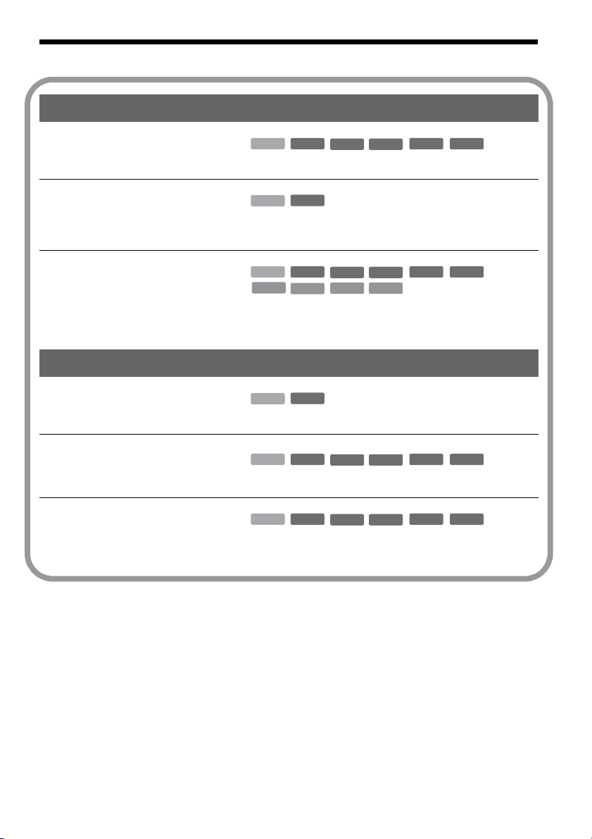
Ways to Use Your DVD Recorder
Ali
Recording/Playback Compatible media and reference pages
Quick access to recorded titles
– Title List
Play the beginning of a title
while it is being recorded
– Chasing Playback
Watching one title while
recording another
– Simultaneous Rec and Play
,
,
,
HDD
+
RW
-
RWVR-RW
Video
+
R
“3. Playing the Recorded Program (Title List)” on page 32
-
HDD
RWVR
“Playing from the beginning of the program you are
recording (Chasing Playback)” on page 56
HDD
VCD
+
RW
CD
-
RWVR-RW
DATA DVD
DATA CD
Video
+
R
“Playing a previous recording while making another
(Simultaneous Rec and Play)” on page 57
Dubbing/Editing Compatible media and reference pages
Creating your own program
– Playlist
Copying a recorded title to and
from the HDD
– Dubbing (HDD y DVD)
Automatic dubbing of DV tapes
– DV/Digital8 Dubbing
,
,
,
-
HDD
RWVR
“Creating and Editing a Playlist” on page 68
HDD
+
RW
-
RWVR-RW
Video
+
R
“Dubbing (HDD y DVD)” on page 70
HDD
+
RW
-
RWVR-RW
Video
+
R
“DV/Digital8 Dubbing” on page 75
-
R
-
R
-
R
-
R
st of recordable and playablediscs is on page 8.
7
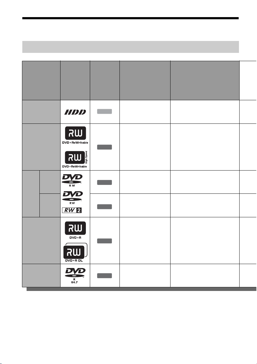
Quick Guide to Disc Types
Recordable and playable discs
Type Disc Logo
Hard disc drive
(internal)
DVD+RW
VR
mode
DVDRW
Video
mode
DVD+R
DVD+R DL
Icon used in
this manual
*2
HDD
+
RW
-
RWVR
-
RW
+
Formatting
(new discs)
(Formatting
unnecessary)
Automatically
formatted in +VR
mode
Format in VR mode
(page 29)
Format in Video mode
Video
(page 29)
R
Automatically
formatted
Compatibility with other DVD
players (finalizing)
Dub HDD contents to a DVD to
play on other DVD players
Playable on DVD+RW
compatible players
(automatically finalized)
Playable only on VR mode
compatible players (finalization
unnecessary)
Playable on most DVD players
(finalization necessary)
(page 38)
Playable on most DVD players
(finalization necessary)
(page 38)
DVD-R
-
R
Usable disc versions (as of March 2005)
• 8x-speed or slower DVD+RWs
• 6x-speed or slower DVD-RWs (Ver.1.1, Ver.1.2
with CPRM
*1
)
• 16x-speed or slower DVD+Rs
• 16x-speed or slower DVD-Rs (Ver.2.0, Ver.2.1)
• 2.4x-speed DVD+R DL (Double Layer) discs
8
Automatically
formatted
“DVD+RW,” “DVD-RW,” “DVD+R,” “DVD+R DL,”
and “DVD-R” are trademarks.
*1
CPRM (Content Protection for Recordable Media) is
a coding technology that protects copyrights for
images.
*2
This logo applies to 4x and 6x speed DVD-RW discs.
Playable on most DVD players
(finalization necessary)
(page 38)

Recording Features Editing Features
Rewrite
(page 40)
Auto
Chapter
(page 85)
Manual
Chapter
(page 67)
Record
16:9 sizes
(page 44)
Change
title name
(page 64)
Delete
title
(page 66)
A-B Erase
(page 65)
Yes Yes Yes Yes Yes Yes Yes Yes
Yes Yes No No Yes Yes Yes No
Yes Yes Yes Yes Yes Yes Yes Yes
Yes Yes No Yes
No Yes No No Yes Yes
*3
Yes Yes No No
*4
No No
Playlist
(page 68)
No Yes No Yes
*3
Discs that cannot be recorded on
• 8 cm discs
• DVD-Rs in VR mode (Video Recording format)
Yes Yes
*3
Only if the recording mode is LSP, SP, HSP, or HQ,
and “DVD Rec. Picture Size” is set to “16:9.”
*4
Erasing titles does not free up disc space.
*4
No No
,continued
9
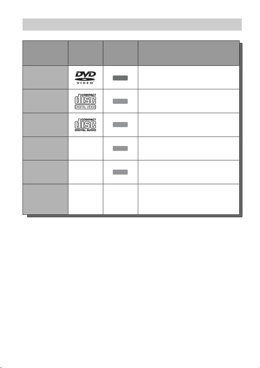
Playable discs
Type Disc Logo
DVD VIDEO
VIDEO CD
CD
DATA DVD —
DATA CD —
8 cm DVD+RW/
DVD-RW/DVD-R
——
Icon used
in this
manual
DVD
VCD
CD
DATA DVD
DATA CD
Characteristics
Discs such as movies that can be purchased or
rented
VIDEO CDs or CD-Rs/CD-RWs in VIDEO
CD/Super VIDEO CD format
Music CDs or CD-Rs/CD-RWs in music CD
format that can be purchased
DVD+RWs/DVD+Rs/DVD-RWs/DVD-Rs/
DVD-ROMs containing JPEG image files
CD-ROMs/CD-Rs/CD-RWs containing MP3
audio tracks or JPEG image files
8 cm DVD+RW, DVD-RW, and DVD-R
recorded with a DVD video camera.
(Still images recorded with a DVD video
camera cannot be played.)
“DVD VIDEO” and “CD” are trademarks.
Discs that cannot be played
•PHOTO CDs
• CD-ROMs/CD-Rs/CD-RWs that are not
recorded in music CD or Video CD format, or do
not contain MP3 or JPEG files
• Data part of CD-Extras
• DVD-ROMs that do not contain JPEG files or
are not in DVD Video format
• DVD Audio discs
• DVD-RAMs
• HD layer on Super Audio CDs
• DVD VIDEOs with a different region code
(page 11)
• DVD-Rs recorded in VR mode (Video
Recording format)
• A disc recorded in a color system other than
NTSC, such as PAL
10
Maximum recordable number of titles
Disc Number of titles*
HDD 300
DVD-RW/DVD-R 99
DVD+RW/DVD+R 49
DVD+R DL 49
* The maximum length for each title is eight hours.
Note on playback operations of DVD VIDEOs/
VIDEO CDs
Some playback operations of DVD VIDEOs/
VIDEO CDs may be intentionally set by software
producers. Since this recorder plays DVD
VIDEOs/VIDEO CDs according to the disc
contents the software producers designed, some
playback features may not be available. Also, see
the instructions supplied with the DVD VIDEOs/
VIDEO CDs.
Region code (DVD VIDEO only)
Your recorder has a region code printed on the rear
of the unit and will only play DVD VIDEOs
(playback only) labeled with identical region
codes. This system is used to protect copyrights.
DVD VIDEOs labeled will also play on this
ALL
recorder.
If you try to play any other DVD VIDEO, the
message “Playback prohibited by region code.”
will appear on the TV screen. Depending on the
DVD VIDEO, no region code indication may be
labeled even though playing the DVD VIDEO is
prohibited by area restrictions.
X
RDR–XXXX
00V 00Hz
NO.
00W
Region code
0-000-000-00
Music discs encoded with copyright protection
technologies
This product is designed to play back discs that
conform to the Compact Disc (CD) standard.
Recently, various music discs encoded with
copyright protection technologies are being
marketed by some record companies. Please be
aware that among those discs, there are some that
do not conform to the CD standard and may not be
playable by this product.
Note on DualDiscs
A DualDisc is a two sided disc product which
mates DVD recorded material on one side with
digital audio material on the other side.
However, since the audio material side does not
conform to the Compact Disc (CD) standard,
playback on this product is not guaranteed.
b Notes
• Some DVD+RWs/DVD+Rs, DVD-RWs/DVD-Rs, or
CD-RWs/CD-Rs cannot be played on this recorder due
to the recording quality or physical condition of the
disc, or the characteristics of the recording device and
authoring software. The disc will not play if it has not
been correctly finalized. For more information, see the
operating instructions for the recording device.
• You cannot mix VR mode and Video mode o n the same
DVD-RW. To change the disc’s format, reformat the
disc (page 29). Note that the disc’s contents will be
erased after reformatting.
• You cannot shorten the time required for recording
even with high-speed discs.
• It is recommended that you use discs with “For Video”
printed on their packaging.
• You cannot add new recordings to DVD+Rs, DVD-Rs,
or DVD-RWs (Video mode) that contain recordings
made on other DVD equipment.
• In some cases, you may not be able to add new
recordings to DVD+RWs that contain recordings made
on other DVD equipment. If you do add a new
recording, note that this recorder will rewrite the DVD
menu.
• You cannot edit recordings on DVD+RWs, DVD-RWs
(Video mode), DVD+Rs, or DVD-Rs that are made on
other DVD equipment.
• If the disc contains PC data unrecognizable by this
recorder, the data may be erased.
• You may not be able to record on some recordable
discs, depending on the disc.
11

Hookups and Settings
Hooking Up the Recorder
Follow steps 1 to 7 to hook up and adjust the
settings of the recorder.
b Notes
• Plug cords securely to prevent unwanted noise.
• Refer to the instructions supplied with the components
to be connected.
• You cannot connect this recorder to a TV that does not
have a video input jack.
• Be sure to disconnect the power cord of each
component before connecting.
Step 1: Unpacking
Check that you have the following items:
• Audio/video cord (phono plug × 3 y phono
plug × 3) (1)
• Power cord (1)
• Antenna cable (1)
• Remote commander (remote) (1)
• Size AA (R6) batteries (2)
Step 2: Connecting the Antenna Cable
Select one of the following antenna hookups. Do
not connect the power cord until you reach
“Step 5: Connecting the Power Cord” on page 19.
If you have Hookup
A: Cable box or satellite receiver
with a video/audio output
B: Cable box with an antenna output
only
C: Cable without cable box, or
antenna only (no cable TV)
b Notes
• If your antenna is a flat cable (300-ohm twin lead
cable), use an external antenna connector (not
supplied) to connect the antenna to the recorder.
• If you have separate cables for VHF and UHF
antennas, use a UHF/VHF band mixer (not supplied) to
connect the antenna to the recorder.
A (page 13)
B (page 14)
C (page 15)
12
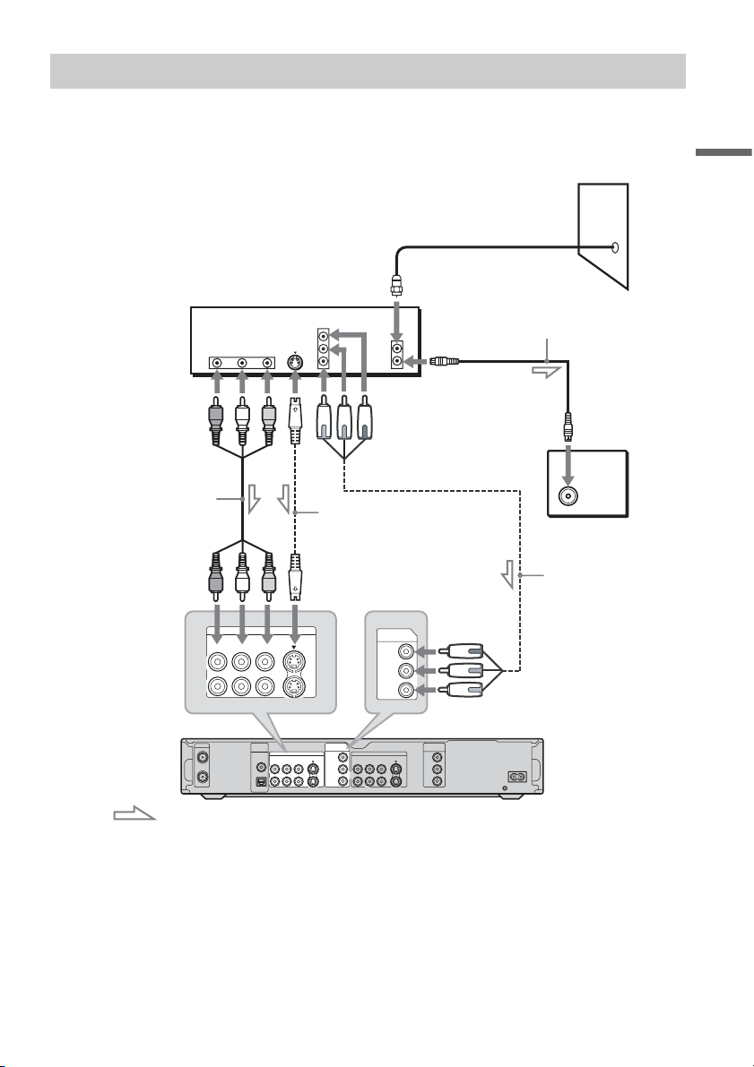
A: Cable box or satellite receiver with a video/audio output
With this hookup, you can record any channel on the cable box or satellite receiver. Be sure that the
satellite receiver or cable box is turned on.
To watch cable or satellite programs, you need to match the channel on the recorder (L1 or L3) to the
input jack connected to the cable box or satellite receiver (LINE IN 1 or 3).
Wall
Hookups and Settings
Cable box/satellite receiver
Audio/video cord
(not supplied)
to LINE IN 1 or 3
VHF/UHF
IN
OUT
AUDIO
OUT
RL
LINE IN
DIGITAL
PCM/DTS/
DOLBY DIGITAL
VIDEO
OUT
VIDEO S VIDEOR-AUDIO-L
OUT
COAXIAL
OPTICAL
S VIDEO
LINE IN
VIDEO S VIDEOR-AUDIO-L
COMPONENT
VIDEO OUT
S-video cord
(not supplied)
1
3
COMPONENT
VIDEO IN
Y
1
PB/ CB
3
R/ CR
P
ANT IN
TO TV
LINE OUT
VIDEO S VIDEOR-AUDIO-L
COMPONENT
VIDEO IN
Y
PB/ CB
P
R/ CR
Antenna cable
(supplied)
to antenna input
TV
Component video cord
(not supplied)
to COMPONENT VIDEO IN
DVD recorder
COMPONENT
VIDEO OUT
Y
1
PB/ C
B
2
PR/ C
R
~AC IN
: Signal flow
b Note
Do not connect a hi-definition tuner using the component video cords. This recorder only accepts standard definition
interlace signals.
z Hints
• If your cable box or satellite receiver has an S-video jack, you can use an S-video cord (not supplied) instead of the
audio/video cord.
• If you connect an S-video cord to the LINE IN 1 jack, set “Line1 Input” in “Video” setup to “S Video” (page 82). If
you connect an S-video cord to the LINE IN 3 jack, set “Line3 Input” in “Video” setup to “S Video” (page 82).
,continued
13
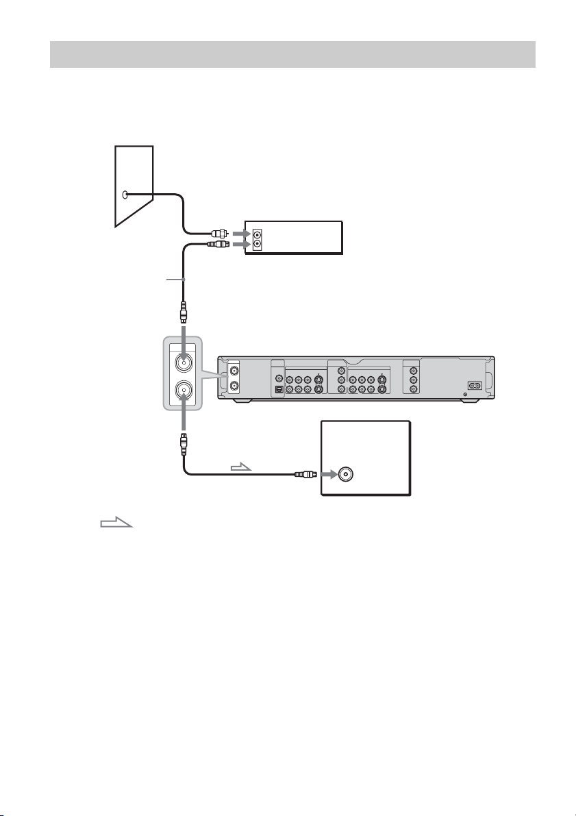
B: Cable box with an antenna output only
With this hookup, you can record any channel on the satellite receiver or cable box. Be sure that the
satellite receiver or cable box is turned on.
To watch cable programs, you need to match the channel on the recorder to the antenna output channel
on the cable box.
Wall
Cable box
ANT IN
TO TV
Antenna cable
(supplied)
to VHF/UHF IN
VHF/UHF
IN
OUT
to VHF/UHF OUT
VHF/UHF
IN
OUT
DIGITAL
OUT
PCM/DTS/
DOLBY DIGITAL
COAXIAL
OPTICAL
COMPONENT
VIDEO IN
LINE IN
VIDEO S VIDEOR-AUDIO-L
LINE OUT
Y
VIDEO S VIDEOR-AUDIO-L
1
PB/ CB
3
R/ CR
P
1
2
TV
COMPONENT
VIDEO OUT
Y
PB/ C
PR/ C
B
R
DVD recorder
~AC IN
to antenna input
: Signal flow
b Note
When using this connection, set “Antenna/Cable” under “Tuner Preset” in “Settings” setup to “Antenna” (page 79).
14
.
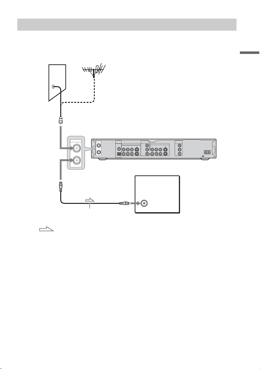
C: Cable without cable box, or antenna only (no cable TV)
Use this hookup if you watch cable channels without a cable box. Also use this hookup if you are using
a VHF/UHF antenna or separate VHF and UHF antennas.
With this hookup, you can record any channel by selecting the channel on the recorder.
Wall
to VHF/UHF IN
VHF/UHF
IN
OUT
to VHF/UHF OUT
VHF/UHF
IN
OUT
DIGITAL
OUT
PCM/DTS/
DOLBY DIGITAL
COAXIAL
OPTICAL
to antenna input
COMPONENT
VIDEO IN
LINE IN
VIDEO S VIDEOR-AUDIO-L
LINE OUT
Y
VIDEO S VIDEOR-AUDIO-L
1
PB/ CB
3
R/ CR
P
1
2
TV
COMPONENT
VIDEO OUT
Y
PB/ C
PR/ C
B
R
DVD recorder
~AC IN
Hookups and Settings
Antenna cable (supplied)
: Signal flow
15
Step 3: Connecting the Video Cords
Select one of the following patterns A through C, according to the input jack on your TV monitor,
projector, or AV amplifier (receiver). This will enable you to view pictures.
A Connecting to a video input jack
You will enjoy standard quality images.
B Connecting to an S VIDEO input jack
You will enjoy high quality images.
C Connecting to component video input jacks (Y, PB/CB, PR/CR)
You will enjoy accurate color reproduction and high quality images.
If your TV accepts progressive 525p format signals, you must use this connection and then press
PROGRESSIVE on the remote to send progressive video signals. For details, see “Using the
PROGRESSIVE button” on page 17.
A
INPUT
VIDEO
L
AUDIO
R
TV, projector, or AV
amplifier (receiver)
VHF/UHF
IN
OUT
Audio/video
cord (supplied)
to LINE OUT (VIDEO) 1 or 2
DIGITAL
PCM/DTS/
DOLBY DIGITAL
OUT
COAXIAL
OPTICAL
COMPONENT
VIDEO IN
LINE IN
Y
VIDEO S VIDEOR-AUDIO-L
1
PB/ CB
3
R/ CR
P
(red)
(yellow)
LINE OUT
VIDEO S VIDEOR-AUDIO-L
Component video
cord (not supplied)
S-video cord
(not supplied)
to LINE OUT (S VIDEO) 1 or 2
DVD recorder
COMPONENT
VIDEO OUT
Y
1
PB/ CB
2
R/ CR
P
(blue)
(green)
~AC IN
INPUT
S VIDEO
B
TV, projector, or AV
amplifier (receiver)
to COMPONENT VIDEO
OUT
COMPONENT
VIDEO IN
C
Y
(green)
PB/CB
(blue)
PR/CR
(red)
TV, projector, or AV
amplifier (receiver)
16
: Signal flow

When playing “wide screen” images
Some recorded images may not fit your TV
screen. To change the picture size, see page 81.
If you are connecting to a VCR
Connect your VCR to the LINE IN jack on the
recorder (page 26).
b Notes
• Do not connect more than one type of video cord
between the recorder and your TV at the same time.
• You cannot use the PROGRESSIVE button with the
connections A and B.
Using the PROGRESSIVE button
By using the PROGRESSIVE button, you can
select the signal format in which the recorder
outputs video signals: interlace or progressive.
1 Connect the recorder using the
COMPONENT VIDEO OUT jacks (pattern
C on page 16).
2 Press the PROGRESSIVE button repeatedly.
“PROGRESSIVE” appears in the front panel
display when the recorder outputs progressive
signals.
Progressive
Select this when:
– your TV accepts progressive signals, and,
– the TV is connected to the COMPONENT
VIDEO OUT jacks.
Note that the pictures will not be clear or no
picture will appear if you select progressive signal
output when either of the above conditions is not
met.
Interlace
Set to this position when:
– your TV does not accept progressive signals, or,
– your TV is connected to jacks other than the
COMPONENT VIDEO OUT jacks (LINE OUT
(VIDEO or S VIDEO)).
Hookups and Settings
z Hint
When you select progressive signal output, you can finetune the signal according to the type of software you are
watching (page 82).
17
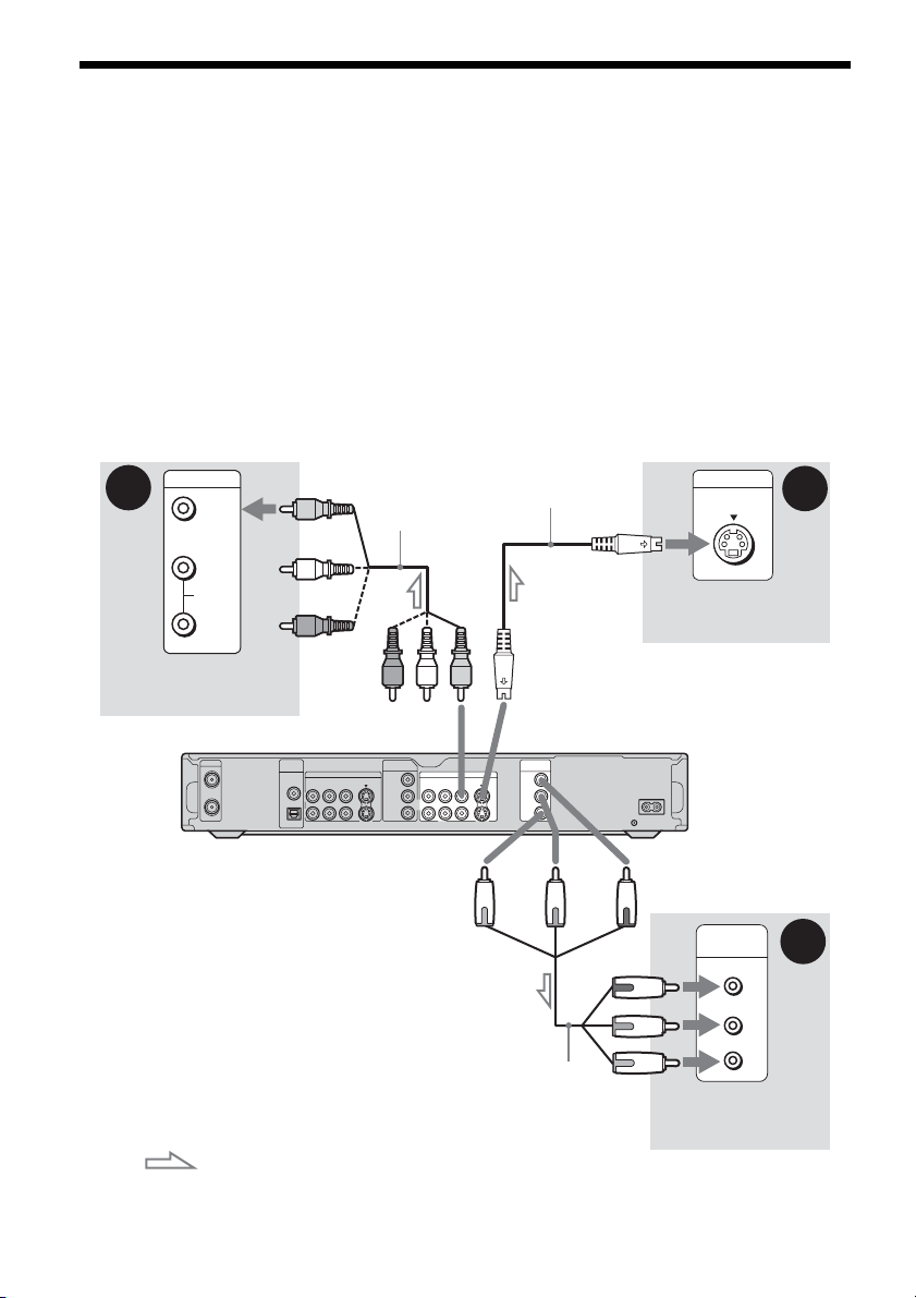
Step 4: Connecting the Audio Cords
Select one of the following patterns A or B, according to the input jack on your TV monitor, projector,
or AV amplifier (receiver). This will enable you to listen to sound.
A Connecting to audio L/R (left/right) input jacks
This connection will use your TV’s or stereo amplifier’s (receiver’s) two speakers for sound. You can
enjoy the following surround effects (page 53).
• TV: Dynamic, Wide, Night
• Stereo amplifier (receiver): Standard, Night
B Connecting to a digital audio input jack
If your AV amplifier (receiver) has a Dolby*1 Digital or DTS*2 decoder and a digital input jack, use this
connection. You can enjoy Dolby Digital (5.1ch) and DTS (5.1ch) surround effects.
(red)
(white)
(yellow)*
LINE OUT
VIDEO S VIDEOR-AUDIO-L
1
2
VHF/UHF
IN
OUT
DIGITAL
OUT
PCM/DTS/
DOLBY DIGITAL
COAXIAL
OPTICAL
DIGITAL
OUT
PCM/DTS/
LINE IN
DOLBY DIGITAL
VIDEO S VIDEOR-AUDIO-L
COAXIAL
OPTICAL
to DIGITAL OUT (COAXIAL or OPTICAL)
Optical digital cord (not supplied)
[Speakers]
to optical digital
input
Rear (L)
Audio/video cord
(yellow)
(supplied)
(white)
(red)
to LINE OUT (R-AUDIO-L) 1 or 2
COMPONENT
VIDEO OUT
VIDEO S VIDEOR-AUDIO-L
Y
1
PB/ CB
2
R/ CR
P
1
3
COMPONENT
VIDEO IN
Y
PB/ CB
R/ CR
P
LINE OUT
or
Coaxial digital cord (not supplied)
to coaxial digital
input
INPUT
VIDEO
L
AUDIO
R
TV, projector, or AV
amplifier (receiver)
DVD recorder
~AC I N
[Speakers]
Rear (R)
A
B
Front (L)
: Signal flow
* The yellow plug is used for video signals (page 16).
18
AV amplifier (re ceiver)
with a decoder
Front (R)
SubwooferCenter

z Hint
For correct speaker location, see the operating
instructions supplied with the connected components.
b Notes
• Do not connect your TV’s audio output jacks to the
LINE IN (R-AUDIO-L) jacks at the same time. This
will cause unwanted noise to come from your TV’s
speakers.
• In the connection A, do not connect the LINE IN (RAUDIO-L) and LINE OUT (R-AUDIO-L) jacks to
your TV’s audio output jacks at the same time. This
will cause unwanted noise to come from your TV’s
speakers.
• In the connection B, after you have completed the
connection, make the appropriate settings under
“Audio Connection” in “Easy Setup” (page 23).
Otherwise, no sound or a loud noise will come from
your speakers.
• With the connection B, the surround sound effects of
this recorder cannot be used.
*1
Manufactured under license from Dolby Laboratories.
“Dolby,” and the double-D symbol are trademarks of
Dolby Laboratories.
*2
“DTS” and “DTS Digital Out” are trademarks of
Digital Theater Systems, Inc.
Step 5: Connecting the Power Cord
Connect the supplied power cord to the AC IN
terminal of the recorder. Then plug the recorder
and TV power cords into an AC outlet. After you
connect the power cord, you must wait for a
short while before operating the recorder.
You can operate the recorder once the front panel
display lights up and the recorder enters standby
mode.
If you connect additional equipment to this
recorder (page 26), be sure to connect the power
cord only after all connections are complete.
~AC I N
1
to AC IN
2
to AC outlet
Hookups and Settings
19

Step 6: Preparing the Remote
You can control the recorder using the supplied
remote. Insert two size AA (R6) batteries by
matching the 3 and # ends on the batteries to the
markings inside the battery compartment. When
using the remote, point it at the remote sensor
on the recorder.
b Notes
• If the supplied remote interferes your other Sony DVD
recorder or player, change the command mode number
for this recorder (page 22).
• Use the batteries correctly to avoid possible leakage
and corrosion. Do not touch the liquid with bare hands
should leakage occur. Observe the following:
– Do not use a new battery with an old battery, or
batteries of different manufacturers.
– Do not attempt to recharge the batteries.
– If you do not intend to use the remote for an extended
period of time, remove the batteries.
– If battery leakage occurs, wipe out any liquid inside
the battery compartment, and insert new batteries.
• Do not expose the remote sensor (marked on the
front panel) to strong light, such as direct sunlight or
lighting apparatus. The recorder may not respond to the
remote.
Controlling TVs with the remote
You can adjust the remote’s signal to control your
TV.
If you connected the recorder to an AV amplifier
(receiver), you can use the supplied remote to
control the AV amplifier’s (receiver’s) volume.
b Notes
• Depending on the connected unit, you may not be able
to control your TV or AV amplifier (receiver) with
some or all of the buttons below.
• If you enter a new code number, the code number
previously entered will be erased.
• When you replace the batteries of the remote, the code
number may be reset to the default setting. Set the
appropriate code number again.
Number
buttons, SET
1 2 3
4 6
5
7 8 9
0
TV/DVD switch
[/1
CH +/–
VOL +/–
TV/VIDEO
WIDE MODE
1 Slide the TV/DVD switch to TV.
2 Hold down [/1.
3 Enter your TV’s manufacturer code (see
“Code numbers of controllable TVs”
below) using the number buttons.
20

4 Release [/1.
When the TV/DVD switch is set to TV, the
remote performs the following:
Buttons Operations
[/1 Turns your TV on or off
VOL +/– Adjusts the volume of
CH +/– Selects the channel on
WIDE MODE Switches to or from the
TV/VIDEO Switches your TV’s
Number buttons
and SET
Code numbers of controllable TVs
If more than one code number is listed, try
entering them one at a time until you find the one
that works with your TV.
Manufacturer Code number
Sony 01 (default)
Akai 04
AOC 04
Centurion 12
Coronado 03
Curtis-Mathes 12, 14
Daewoo 04, 22
Daytron 03, 12
Fisher 11
General Electric 04, 06, 10
Gold Star/LG 03, 04, 17
Hitachi 02, 03, 04
J.C.Penney 04, 10, 12
JVC 09
KMC 03
Magnavox 03, 04, 08, 12, 21
Marantz 04, 13
MGA/Mitsubishi 04, 12, 13, 17
NEC 04, 12
Panasonic 06, 19
your TV
your TV
wide mode of a Sony
wide-screen TV
input source
Selects the channel on
your TV
Manufacturer Code number
Philco 02, 03, 04, 08
Philips 08, 21
Pioneer 06, 16
Portland 03
Proscan 10
Quasar 06, 18
Radio Shack 05, 10, 14
RCA 04, 10
Sampo 12
Samsung 03, 04, 12, 20
Sanyo 11, 14
Scott 12
Sears 07, 10, 11
Sharp 03, 05, 18
Sylvania 08, 12
Teknika 03, 08, 14
Toshiba 07, 18
Wards 03, 04, 12
Yorx 12
Zenith 14, 15
,continued
Hookups and Settings
21

Controlling the volume of your AV amplifier (receiver) with the remote
TV/DVD switch
[/1
1 2 3
4 6
Number buttons
5
7 8 9
0
VOL +/–
1 Slide the TV/DVD switch to DVD.
2 Hold down [/1, and enter the
manufacturer code (see the table below)
for your AV amplifier (receiver) using the
number buttons.
3 Release [/1.
The VOL +/– buttons control the AV
amplifier’s volume.
If you want to control the TV’s volume, slide
the TV/DVD switch to TV.
If you have a Sony DVD player or more than one Sony DVD recorder
If the supplied remote interferes with your other
Sony DVD recorder or player, set the command
mode number for this recorder and the supplied
remote to one that differs from the other Sony
DVD recorder or player.
The default command mode setting for this
recorder and the supplied remote is DVD3.
1 2 3
4 6
5
7 8 9
0
SYSTEM
MENU
M/m,
O RETURN
ENTER
z Hint
If you want to control the TV’s volume even when the
TV/DVD switch is set to DVD, repeat the steps above
and enter the code number 90 (default).
Code numbers of controllable AV amplifiers
(receivers)
If more than one code number is listed, try
entering them one at a time until you find the one
that works with your AV amplifier (receiver).
Manufacturer Code number
Sony 78, 79, 80, 91
Denon 84, 85, 86
Kenwood 92, 93
Onkyo 81, 82, 83
Pioneer 99
Sansui 87
Technics 97, 98
Yamaha 94, 95, 96
22
COMMAND
MODE
switch
1 Press SYSTEM MENU.
The System Menu appears.
2 Select “SETUP,” and press ENTER.
SETUP
Settings
Video
Audio
Features
Options
Easy Setup
Tuner Preset
Set G-Code Channels
Clock
Language

3 Select “Options,” and press ENTER.
SETUP
Format DVD-RW : VR
Settings
Video
Audio
Features
Options
Easy Setup
Dimmer :
Power Save :
Auto Display :
Auto Stereo :
Tuner Audio :
Command Mode :
Factory Setup
Normal
Off
On
On
Main
DVD3
4 Select “Command Mode,” and press
ENTER.
SETUP
Format DVD-RW : VR
Settings
Video
Audio
Features
Options
Easy Setup
Dimmer :
Power Save :
Auto Display :
Auto Stereo :
Tuner Audio :
Command Mode :
Factory Setup
DVD1
DVD2
DVD3
Normal
Off
On
Off
On
DVD3
5 Select the Command mode (DVD1, DVD2,
or DVD3), and press ENTER.
6 Slide the COMMAND MODE switch on the
remote so it matches the mode you
selected above.
To return to the previous step
Press O RETURN.
Check that the command mode switch on the
remote is set to the default setting of DVD3
before you try to change the command mode for
the recorder. If the command mode for the remote
is changed to DVD1 or DVD2, you may be
unable to operate this recorder.
Step 7: Easy Setup
Make the basic adjustments by following the onscreen instructions in “Easy Setup.”
[/1
O RETURN
1 2 3
4 6
5
7 8 9
0
CH +/–
</M/m/,,
ENTER
1 Turn on the recorder and switch the input
selector on your TV so that the signal from
the recorder appears on your TV screen.
The message about the initial settings appears.
• If this message does not appear, select “Easy
Setup” from “SETUP” in the System Menu
to run “Easy Setup” function (“Settings and
Adjustments” on page 79).
2 Press ENTER.
Follow the on-screen instructions to make the
following settings.
Language
Select the language for the on-screen displays.
Clock
Select “Manual,” and set the clock using
, and press ENTER. Do not select
m/,
“Auto.” This setting cannot be used in your
area.
Tuner Preset
Select whether or not you have a cable
connection.
The Tuner Preset function automatically
searches for all of the receivable channels and
presets them.
To set the channels manually, see page 79.
</M/
Hookups and Settings
,continued
23

TV Type
If you have a wide-screen TV, select “16:9.”
If you have a standard TV, select either “4:3
Letter Box” (shrink to fit) or “4:3 Pan Scan”
(stretch to fit). This will determine how
“wide-screen” images are displayed on your
TV.
Audio Connection
If you connected an AV amplifier (receiver)
using either a digital optical or coaxial cord,
select “Yes: DIGITAL OUT” and set the
digital output signal (page 84).
3 Press ENTER when “Finish” appears.
“Easy Setup” is finished.
To return to the previous step
Press O RETURN.
z Hint
If you want to run “Easy Setup” again, select “Easy
Setup” from “SETUP” in the System Menu (page 88).
Setting Up the G-Code
®
System
Setting up your recorder involves coordinating the
TV channel number (the number you turn to on
your TV or recorder to watch a program) with the
guide channel (the number that’s assigned to that
channel in your TV program guide). Note that this
feature may not be available in some areas.
To find the guide channel numbers, look at the
“Channel Line-up Chart” in the program guide for
your area that features G-Code numbers.
Use the Channel Line-up Chart to coordinate the
guide channel number with the TV channel
number. For example, if HBO is listed in the
Channel Line-up Chart as channel 33, and the
recorder receives HBO on channel 5, coordinate
these numbers using the following procedure.
b Note
If you use an S-video cord to connect your cable box or
satellite receiver, set “Line1 Input” or “Line3 Input” in
“Video” setup to “S Video” (page 82).
Number
buttons, SET
SYSTEM MENU
O RETURN
1 2 3
4 6
5
7 8 9
0
</M/m/,,
ENTER
1 Press SYSTEM MENU while the recorder is
stopped.
2 Select “SETUP,” and press ENTER.
SETUP
Settings
Video
Audio
Features
Options
Easy Setup
Tuner Preset
Set G-Code Channels
Clock
Language
24

3 Select “Settings,” and press ENTER.
4 Select “Set G-Code Channels,” and press
ENTER.
Settings - Set G-Code Channels
Guide CH TV CH
- -
Channel list
- -
----
5 Select “Guide CH – TV CH,” and press
ENTER.
Settings - Set G-Code Channels
Guide CH TV CH
- -
- - ----
- -
- -
6 Enter the guide channel number assigned
in the program guide using the number
buttons, and press SET.
Settings - Set G-Code Channels
Guide CH TV CH
33
- - ----
- -
33
7 Enter the TV channel number using the
number buttons, and press SET.
Settings - Set G-Code Channels
Guide CH TV CH
33
- - ----
- -
5
To return to the previous step
Press O RETURN.
To check the channel settings
When displaying the “Set G-Code Channels”
menu, select “Channel List,” then press ENTER.
The display lists the channels for which the guide
channel number does not match the TV channel
number.
Settings - G-Code Channel List
Guide CH TV CH
2
-
4
-
6
-
10
-
11
-
25
-
28
-
21
32
9
121
13
36
2
Guide CH TV CH
Close
45
53
- -
- -
- -
- -
- -
Page1
-
18
-
5
-
- -
-
- -
-
- -
-
- -
-
- -
To go to the next page, press m.
To return to the previous page, press M.
Hookups and Settings
If you made Hookup A (page 13) or Hookup
C (page 15), enter the TV channel number on
your cable box.
If you made Hookup B (page 14), enter the
cable box output channel. See the instructions
supplied with your cable box to confirm the
cable box’s output channel.
8 Repeat steps 5 to 7 for each guide channel
number that does not match the TV channel
number.
9 Press SYSTEM MENU repeatedly to exit the
menu.
25
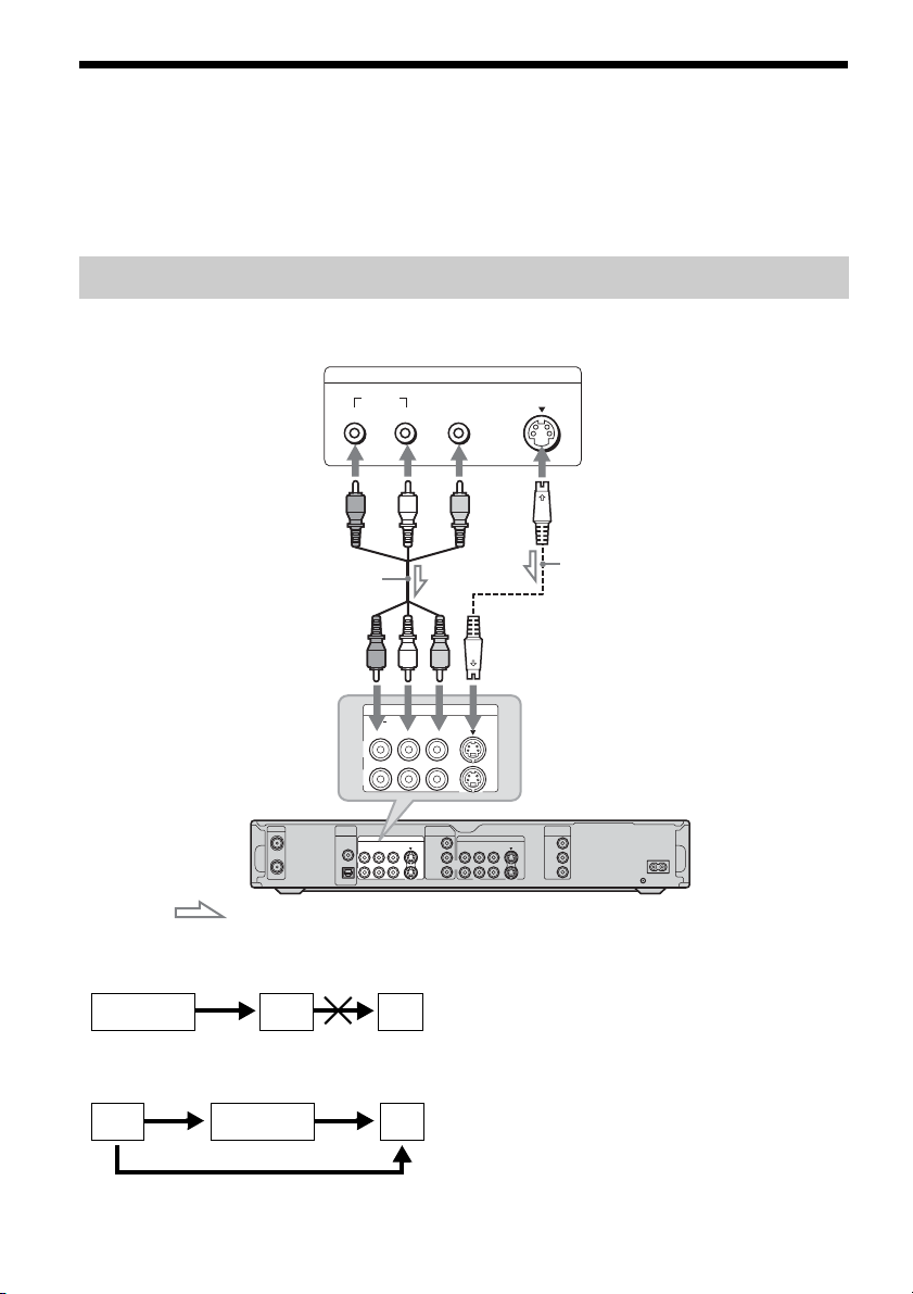
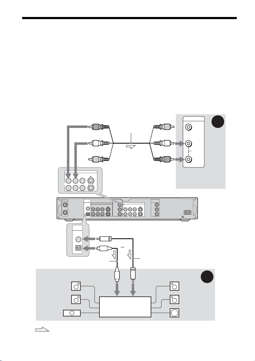
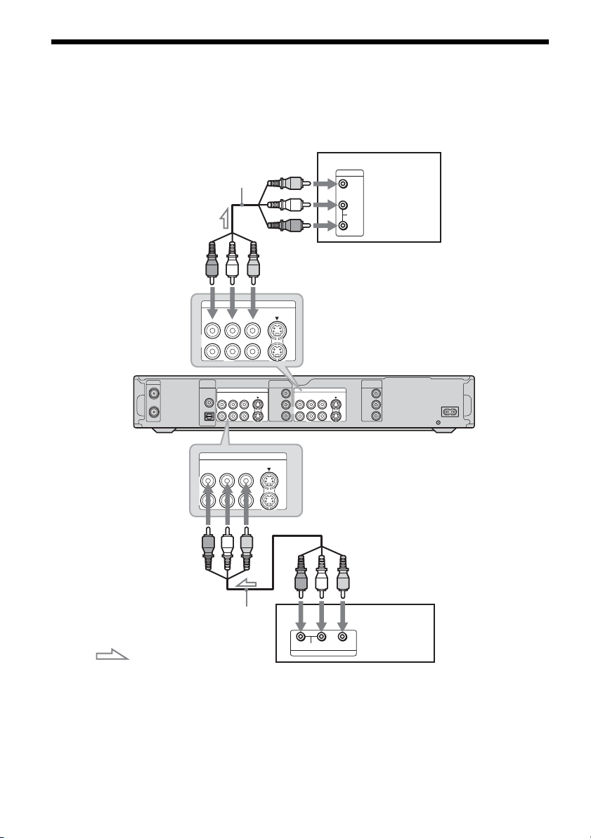
Connecting a VCR or Similar Device
After disconnecting the recorder’s power cord from an AC outlet, connect a VCR or similar recording
device to the LINE IN jacks of this recorder.
Use the DV IN jack on the front panel if the equipment has a DV output jack (i.LINK jack) (page 75).
See also the instruction manual supplied with the connected equipment.
To record on this recorder, see “Recording from connected equipment without a timer” on page 50.
Connecting to the LINE IN 1 or 3 jacks
Connect a VCR or similar recording device to the LINE IN 1 or 3 of this recorder. If the equipment has
an S-video jack, you can use an S-video cord instead of an audio/video cord.
LINE OUTPUT
AUDIO
RL
VIDEO
VCR, etc.
S Video
Audio/video cord
(not supplied)
S-video cord
(not supplied)
to LINE IN 1 or 3
LINE IN
S VIDEO
VIDEO
AUDIORL
1
3
VHF/UHF
IN
OUT
DIGITAL
OUT
PCM/DTS/
DOLBY DIGITAL
COAXIAL
OPTICAL
COMPONENT
VIDEO IN
LINE IN
VIDEO S VIDEOR-AUDIO-L
LINE OUT
Y
VIDEO S VIDEOR-AUDIO-L
1
PB/ CB
3
R/ CR
P
1
2
COMPONENT
VIDEO OUT
Y
PB/ CB
R/ CR
P
DVD recorder
~AC IN
: Signal flow
b Notes
• Pictures containing copy protection signals that prohibit any copying cannot be recorded.
• If you pass the recorder signals via the VCR, you may not receive a clear image on your TV screen.
VCRDVD recorder TV
Be sure to connect your VCR to the DVD recorder and your TV in the order shown below. To watch video tapes,
watch the tapes through a second line input on your TV.
Line input 1
VCR DVD recorder TV
Line input 2
• If you disconnect the recorder’s power cord, you will not be able to view the signals from the connected VCR.
26
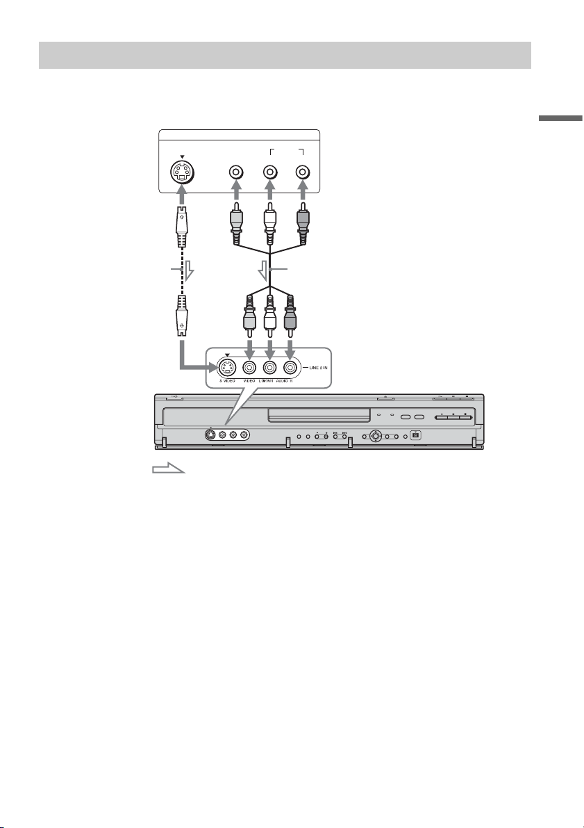
Connecting to the LINE 2 IN jacks on the front panel
Connect a VCR or similar recording device to the LINE 2 IN jacks of this recorder. If the equipment has
an S-video jack, you can use an S-video cord instead of an audio/video cord.
VCR, etc.
OUTPUT
S VIDEO
VIDEO
AUDIO
LR
Hookups and Settings
S-video cord
(not supplied)
to LINE 2 IN DVD recorder
: Signal flow
Audio/video cord
(not supplied)
z Hint
When the connected equipment outputs only monaural sound, connect to just the L (MONO) and VIDEO input jacks
on the front of the recorder. Do not connect the R input jack.
b Notes
• Do not connect the yellow LINE IN (VIDEO) jack when using an S-video cord.
• Do not connect the output jack of this recorder to another equipment’s input jack with the other equipment’s output
jack connected to the input jack of this recorder. Noise (feedback) may result.
• Do not connect more than one type of video cord between the recorder and your TV at the same time.
27
Connecting to a Satellite or Digital Tuner
Connect a satellite or digital tuner to this recorder using the LINE IN 1 jacks. Disconnect the recorder’s
power cord from an AC outlet when connecting the tuner.
To use the Synchro-Rec function, see below.
TV
VHF/UHF
IN
OUT
to LINE IN 1
Audio/video cord
(supplied)
LINE OUT
VIDEO S VIDEOR-AUDIO-L
DIGITAL
OUT
PCM/DTS/
LINE IN
DOLBY DIGITAL
VIDEO S VIDEOR-AUDIO-L
COAXIAL
OPTICAL
LINE IN
VIDEO S VIDEOR-AUDIO-L
1
3
COMPONENT
VIDEO IN
Y
PB/ CB
R/ CR
P
1
2
1
3
INPUT
VIDEO
L
AUDIO
R
to LINE OUT
LINE OUT
VIDEO S VIDEOR-AUDIO-L
1
2
COMPONENT
VIDEO OUT
Y
PB/ CB
R/ CR
P
DVD recorder
~AC I N
Audio/video cord
(not supplied)
: Signal flow
If you want to use the Synchro Rec function
This connection is necessary to use the SynchroRecording function. See “Recording from
connected equipment with a timer (Synchro Rec)”
on page 49.
28
Satellite tuner, etc.
VIDEO
L
R
AUDIO
OUTPUT
b Notes
• Synchro-Recording does not work with some tuners.
For details, see the tuner’s operating instructions.
• If you disconnect the recorder’s power cord, you will
not be able to view the signals from the connected
tuner.
Seven Basic Operations
— Getting to Know Your DVD Recorder
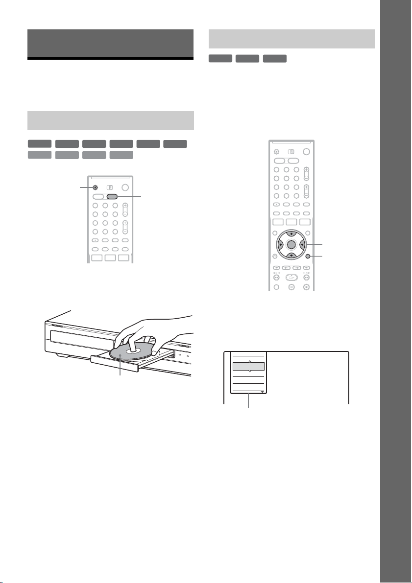
1. Inserting and Formatting a DVD Disc (Disc Info)
Inserting a Disc
Formatting a DVD disc (Disc Info)
+
-
RWVR-RW
RW
New discs are automatically formatted when
inserted. If necessary, you can manually re-format
a DVD+RW or DVD-RW disc to make a blank
disc. For DVD-RWs, you can select a recording
format (VR mode or Video mode) according to
your needs (page 8).
Video
Seven Basic Operations — Getting to Know Your DVD Recorder
+
RW
VCD
Press DVD.
1
-
RWVR-RW
CD
Z OPEN/
CLOSE
DATA DVD
Video
1 2 3
4 6
5
7 8 9
0
+
R
DATA CD
-
R
DVD
DVD
2 Press Z OPEN/CLOSE, and place a disc on
the disc tray.
With the recording/playing side facing down
3 Press Z OPEN/CLOSE to close the disc
tray.
Wait until “LOAD” disappears from the front
panel display.
Unused DVDs are formatted automatically.
1 2 3
4 6
5
7 8 9
0
</M/m/,,
ENTER
TOOLS
1 Insert a disc.
See “Inserting a Disc” on page 29.
2 Press TOOLS.
The TOOLS menu appears.
Close
Stop
Erase Title
Protect Title
Dubbing
Options for the disc or picture
The TOOLS menu displays options
applicable to the entire disc (e.g. disc
protection), recorder (e.g. audio settings
during recording), or multiple items on a list
menu (e.g. erasing multiple titles). The
displayed options differ depending on the
situation and disc type.
,continued
29
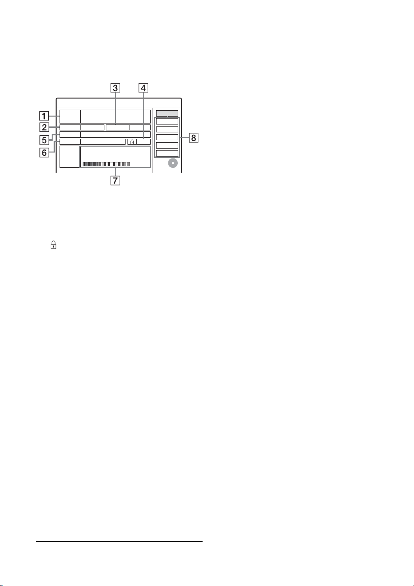
3 Move the cursor down the TOOLS menu
until “Disc Info” is selected, and press
ENTER.
Example: When a DVD-RW (VR mode) is
inserted.
Disc Information
DiscName Movie
Media DVD-RW Format VR
Original 3 / Playlist
Title no. 2
10/13/2005 ~ 10/28/2005
Date Off
HQ : 0H30M HSP : 0H45M SP : 1H00M
Remainder
LSP : 1H15M LP : 1H30M EP : 2H00M
SLP : 3H00M SEP : 4H00M
1 “Disc Name” (DVD only)
2 “Media”: Disc type
3 “Format”: Recording format type (DVD-
RW only)
4 “On”/“Off”: Indicates whether
protection is set (DVD-RW in VR mode
only)
5 “Title no.”: Total number of titles
6 “Date”: Dates of when the oldest and the
most recent titles were recorded (DVD
only)
7 “Continuous Rem. Time”/“Remainder”
(approximate)
• The remaining recording time in each of the
recording modes
• Disc space bar
• Remaining disc space/total disc space
8 Disc setting buttons
“Disc Name” (page 37)
“Protect Disc” (page 38)
“Finalize”/“Unfinalize” (page 38)
“Erase All” (page 67)
“Format”
2. 3 / 4. 7
GB
Close
Disc Name
Protect Disc
Finalize
Erase All
Format
z Hints
• By reformatting, you can change the recording format
on DVD-RWs, or record again on DVD-RWs that have
been finalized.
• For DVD+RWs and DVD-RWs (Video mode), you can
check free space and title location on the disc using the
Disc Map display (page 67).
b Note
On this model, 1 GB (read “gigabyte”) is equivalent to 1
billion bytes. The larger the number, the larger the disc
space.
Available settings differ depending on the
disc type.
4 Select “Format,” and press ENTER.
5 Select “OK,” and press ENTER.
For DVD-RWs, select “VR” or “Video,” and
press ENTER.
All contents on the disc are erased.
30
 Loading...