

Page 1

Remote Contr ol
P anel
3-859-859-13(1)
Operating Instructions
Before operating the unit, please read this manual
thoroughly and retain it for future reference.
RCP-TX7
1997 by Sony Corporation
Page 2

For the customers in the USA
This equipment has been tested and found to comply with the
limits for a Class A digital device, pursuant to Part 15 of the
FCC Rules. These limits are designed to provide reasonable
protection against harmful interference when the equipment
is operated in a commercial environment. This equipment
generates, uses, and can radiate radio frequency energy
and, if not installed and used in accordance with the
instruction manual, may cause harmful interference to radio
communications. Operation of this equipment in a residential
area is likely to cause harmful interference in which case the
user will be required to correct the interference at his own
expense.
You are cautioned that any changes or modifications not
expressly approved in this manual could void your authority
to operate this equipment.
This device requires shielded interface cables to comply with
FCC emission limits.
2
Page 3

Table of Contents
Overview ............................................................................4
Location and Function of Parts .......................................5
Operation Panel and Connector........................................... 5
1 Main Operation Section................................................ 5
2 Menu Operation/Setting Display Section..................... 7
3 Paint section and CALL button .................................... 8
Menu Operations.............................................................12
Displaying menus.............................................................. 12
Basic Menu Operations ..................................................... 14
Menu Contents .................................................................. 15
File Operations ................................................................21
Operating Scene Files........................................................ 23
Operating Setup Files (for DXC-D30/D30P Only)........... 24
Skin Detail Correction/Skin Matrix Adjustment
(for DXC-D30/D30P Only) ...........................................25
Multi-Camera Control......................................................26
Operating Multiple Cameras from One RCP Unit
— Command Link........................................................ 26
Adjusting the Iris and Master Black of Multiple Cameras
at One Time.................................................................. 27
Data Transfer Among Multiple Cameras .......................... 27
Specifications..................................................................28
3
Page 4

Overview
Overview
The RCP-TX7 Remote Control Panel enables remote
operation of the DXC-D30/D30P or DXC-637 series
Color Video Camera.
This unit’s features are described below.
Connectable to camera control unit or
camera head
When a CCU (CCU-TX7/TX7P Camera Control Unit)
has been connected to a CA (CA-TX7/TX7P Camera
Adaptor) that is docked with a camera head, this unit
can be connected to the CCU to enable remote
operation of the camera via the CCU.
When the DXC-D30/D30P is docked with a CA-537/
537P Camera Adaptor or VCR, this unit can be
connected to the DXC-D30/D30P to enable direct
operation of the camera.
Full control of shooting operations
Besides controlling camera adjustments and settings,
this unit can control tripod operations (pan and tilt) and
lens settings (focus and zoom).
High-precision and high-speed control
Commands can be issued at high speed, which means
that remote operation with the unit’s knobs can be
performed more smoothly than with previous remote
control devices. Also, high-precision data transfer
raises control precision.
Confirmation of camera conditions and
operation status
This unit’s LCD panel indicates camera conditions
such as the optical filter position, value, and lens
extender setting. The results of the camera’s selfdiagnosis tests are also displayed on the LCD panel.
Scene file
The unit provides memory to hold data on shooting
conditions for 16 different scenes, to enable easy
readjustment of the camera for any memorized scenes.
Coordination of settings among several
cameras
In a system that includes several cameras that are
connected via CCUs, connecting the CCUs allows this
unit to set up all of the cameras into the same color
condition.
4
Page 5
Location and Function of Parts
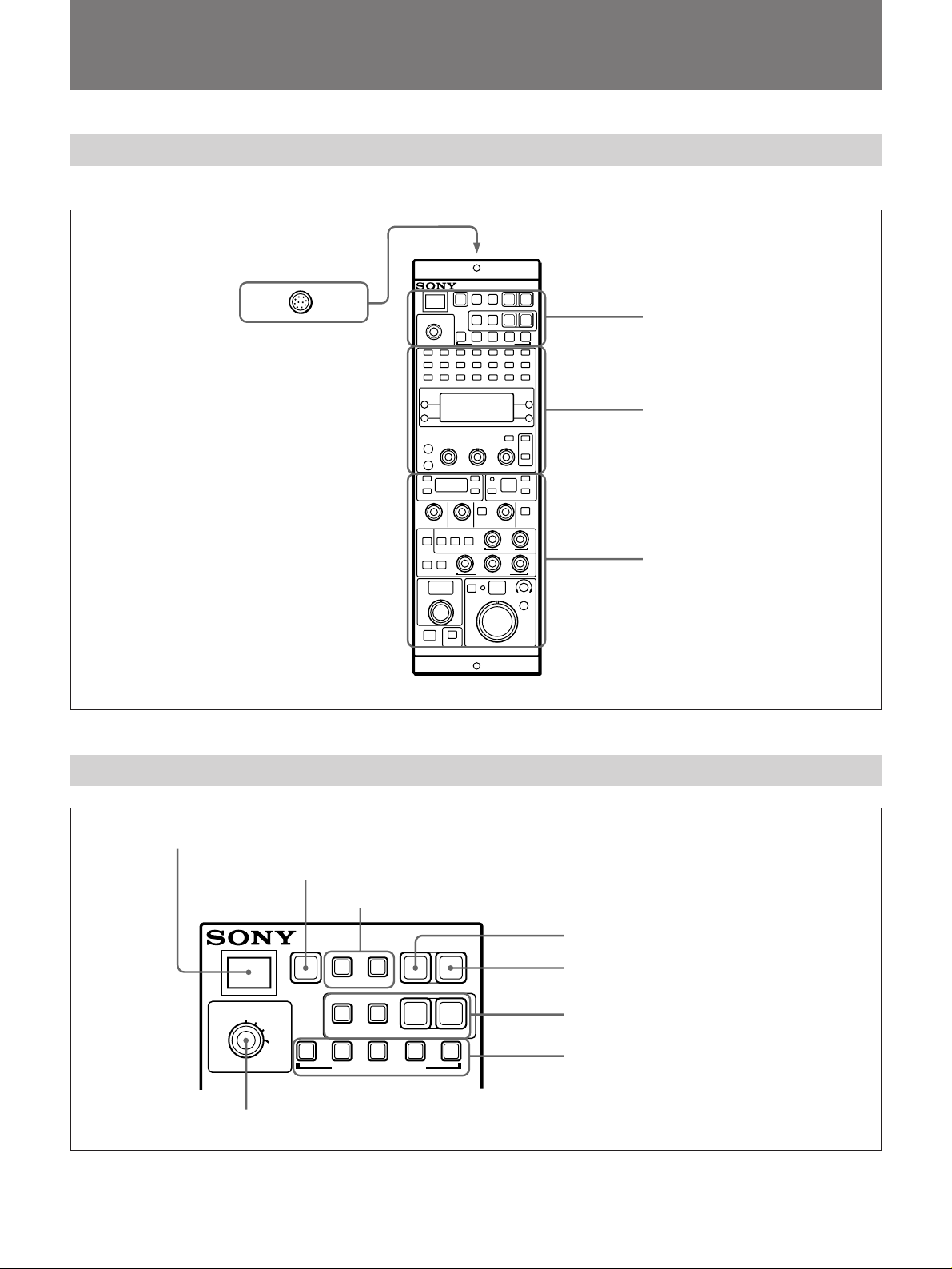
Operation Panel and Connector
The following figure shows external views of this unit.
CCU/camera connector
(10-pin): Use the
supplied cable to connect
this unit to a CCU or
camera head. The power
supply to this unit and the
signal exchange are both
carried out via this
connector.
1 Main operation section
2 Menu operation/setting display
section (see page 7)
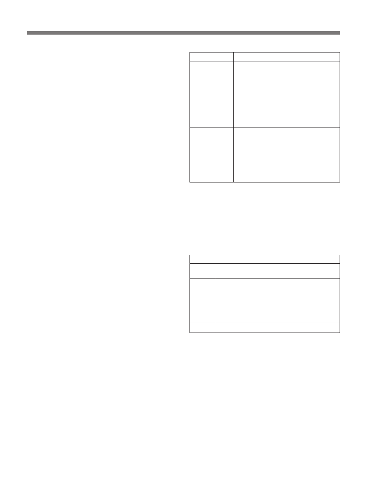
1 Main Operation Section
1 TALLY indicator
2 STANDARD button
3 MASTER and SLAVE buttons
MASTER SLAVE
STANDARD
PULL
OPERATE
PAINT
IRIS/M.
BLACK
LOCK
AUTO SETUP
SKIN
DETAIL
RGB
MONITOR SELECT
LEVEL
Operation panel
CAM POWER
WHITE BLACK
SEQ
REMOTE CONTROL PANEL
BARS
ENC
3 Paint section and CALL button
(see page 8)
4 CAM POWER switch
5 BARS button
6 AUTO SETUP buttons
7 MONITOR SELECT buttons
8 OPERATE knob
5
Page 6
Location and Function of Parts
1 TALLY indicator
Lights in red when a red tally signal from the CA or
CCU is received and lights in green when a green tally
signal is received.
2 STANDARD button
Press to automatically set up the camera for use under
standard shooting conditions.
3 MASTER and SLAVE buttons (only when this
unit is connected to CCU)
When using several remote control panels connected to
CCUs, press the MASTER button on the unit to be
used as the master unit and press the SLAVE button on
all other units (slave units). Both buttons light when
pressed.
Once a unit has been set as the master unit, the
MASTER button on any other unit cannot be operated.
To select other unit for master unit, press the
MASTER button on the current master unit again.
(The button goes out.)
For details, see “Multi-Camera Control” on page 26.
4 CAM (camera) POWER switch (only when this
unit is connected to CCU)
When the power supply is on for the CCU, CA and
camera head, this switch lights. You can then turn the
power supply for the camera on or off by pressing the
switch. The switch lights when the power is on, and
goes out when the power is off. It takes a moment
until the power is being turned on or off after the
switch is pressed. (The switch blinks meanwhile.)
5 BARS (color bars) button
Press to output color bars from the camera when this
unit has been connected to a camera. When this unit
has been connected to a CCU, press this button to
output color bars from the CCU’s internal color bar
generator.
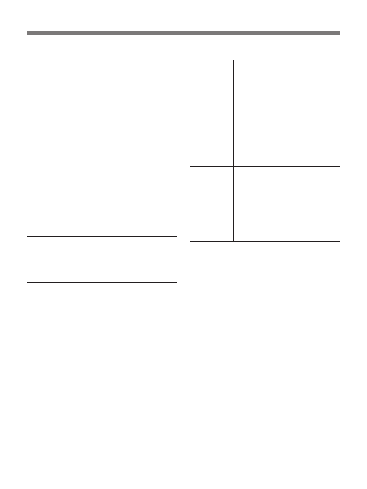
6 AUTO SETUP buttons
Press one of these buttons to set up the camera
automatically for the corresponding item. The buttons
will blink when pressed.
Operations of the button are as follows:.
Button Operation
SKIN DETAIL
(only for DXCD30/D30P)
LEVEL Performs auto white balance or auto
WHITE Performs auto white balance adjustment.
BLACK Performs auto black balance adjustment.
a)Skin gate area: target color range of skin detail correction
or skin matrix adjustment
Recalls the AUTO SKIN menu and
performs automatic designation of the
skin gate area.
black balance adjustments. (During
adjustment, indications appear on the
LCD panel in the menu operation/setting
display 2.) When using a DXC-D30/
D30P, the R/B gamma is set to the
standard value.
(During adjustment, indications appear on
the LCD panel in the menu operation/
setting display 2.)
(During adjustment, indications appear on
the LCD panel in the menu operation/
setting display 2.)
a)
7 MONITOR SELECT buttons (only when this
unit is connected to CCU)
Press one of these buttons to select the type of signal
output via the PIX and WFM connectors on the CCU’s
rear panel. The buttons will light when pressed.
The following signals can be selected.
Button Output signal
R R signal (The G and B signals can be selected at
G
B B signal (The R and G signals can be selected at
SEQ
ENC
the same time.)
G signal (The R and B signals can be selected
at the same time.)
the same time.)
WFM connector: R, G and B sequence signal
PIX connector: signal selected last
Composite video signal
8 OPERATE knob
Locks some of the buttons and knobs on the control
panel.
FULL: No locking.
PAINT: Locks the buttons and knobs except for
those in the paint section 3, CALL button 3,
AUTO SETUP buttons 6 (excluding LEVEL
button) and MONITOR SELECT buttons 7.
IRIS/M.BLACK: Locks the buttons and knobs
except for those in the iris adjustment block and
master black adjustment block in the paint section
3, CALL button 3, and MONITOR SELECT
buttons 7.
LOCK: Locks the buttons and knobs except for the
CALL button 3 and MONITOR SELECT
buttons 7.
6
Page 7
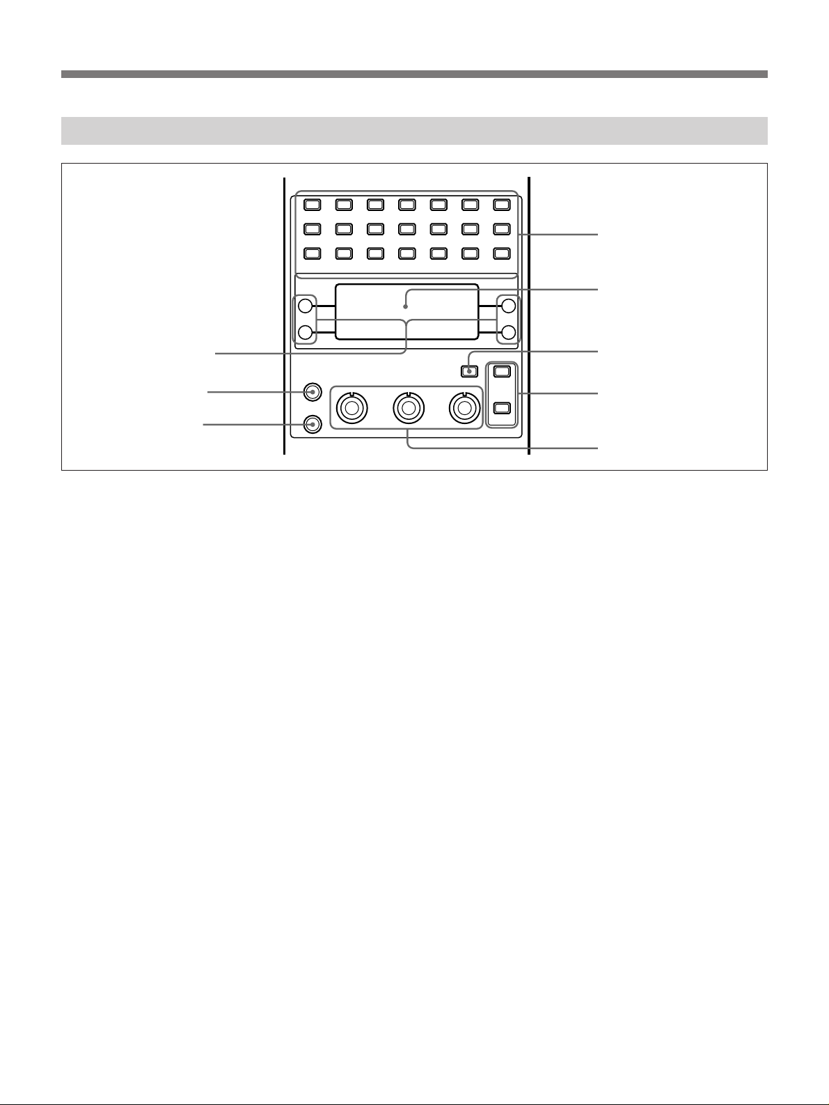
2 Menu Operation/Setting Display Section
8 Setting buttons
7 BRIGHT knob
6 CONTR knob
DETAIL GAMMA
SHADING MATRIX FILTER
DYNA
LATITUDE
BRIGHT
CONTR
KNEE FLARE RECALL STORE
BLACK
TLCS
STRETCH
1 Menu selection buttons
Press one of these buttons to have the corresponding
menu displayed on the LCD panel 2.
For details, see “Basic Menu Operations” page 14.
2 LCD panel
Displays menus, messages reporting the progress or
results of operations, current settings, etc.
3 INDICATION button
Press this button to change indications on the LCD
panel in the following order:
Current settings of detail level, gamma and knee n
Current setting of white balance n Current setting of
black balance n Current setting of flare (when the
FLARE button in the black balance adjustment/flare
correction block is lit) n No indications and back to
current settings of detail level, gamma and knee
If you press this button while a menu is indicated, the
menu indication disappears and then current settings of
detail level, gamma and knee appear.
LENSE PAN/TILT
AUTO
FUNCTION
SKIN
GATE
DIAG OTHERS
INDICATION
SKIN
DETAIL
PAGE
PREV
NEXT
1 Menu selection buttons
2 LCD panel
3 INDICATION button
4 PAGE buttons
5 Setting knobs
5 Setting knobs
Use these knobs to change the settings in various
menus.
For details, see “Basic Menu Operations” on page 14.
6 CONTR (contrast) knob
Adjusts the contrast of the LCD panel 2 display.
7 BRIGHT (brightness) knob
Adjusts the brightness of the LCD panel 2 display.
8 Setting buttons
Use these buttons to select functions or settings in
various menus.
For details, see “Basic Menu Operations” on page 14.
4 PAGE buttons
Press the PREV button to display the previous menu
page or the NEXT button to display the next menu
page. (Each press goes back or forward one page.)
Pressing both buttons simultaneously displays the first
menu page.
For details, see “Basic Menu Operations” on page 14.
7
Page 8
Location and Function of Parts
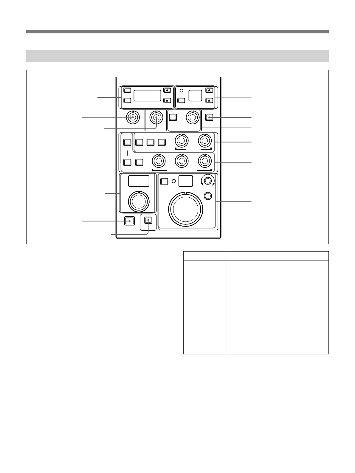
3 Paint section and CALL button
!™ Shutter setting block
!¡ DETAIL knob
0 MASTER GAMMA knob
9 Master black adjustment
block
8 CALL button
7 IRIS/M.BLACK LINK button
C.SCAN
ON/OFF
SHUTTER
AUTO
FLARE
IRIS/M.BLACK
MASTER
PRESET MANUAL
LINK
DETAIL
BLACK
AUTO
MANUAL
MASTER BLACK
CALL
GAMMA
AUTO
REMOTE CONTROL PANEL
1 Master gain setting block
Includes the buttons, a display window, and a DPR
indicator described below.
The setting that can be performed via this block differ
according to the connected camera.
When using a DXC-D30/D30P: Select the gain
value from –3, 0, +3, +6, +9, +12, +18, +24 dB,
and HYPER GAIN. (HYPER GAIN equals 30 dB
+ DPR, but the DPR indicator will not light if it is
selected.)
When using a DXC-637 series camera: Select the
gain level from LOW, MID and HIGH. The gain
value corresponding to each value is set by
camera.
DPR
MASTER GAIN
AUTO
KNEE
WHITE
BLACK/FLARE
EXT
IRIS
SKIN
DETAIL
CLOSE OPEN
COARSE
SENS
1 Master gain setting block
2 SKIN DETAIL button
3 Knee correction block
4 White balance adjustment
block
5 Black balance adjustment/
flare correction block
6 Iris adjustment block
Name Operation
4 (up) button Each press of this button raises the
setting value by one step.
When using the DXC-D30/D30P, press
the up and down buttons simultaneously
to set the master gain to 0 dB.
$ (down) button Each press of this button lowers the
setting value by one step.
When using the DXC-D30/D30P, press
the up and down buttons simultaneously
to set the master gain to 0 dB.
DPR button and
indicator
When the master gain is set at 18 or 24
dB, press this button to activate DPR
function
a)
.
Display window Displays the current master gain value.
a)DPR (Dual Pixel Readout) function: When this function is
active, CCD output signal readout is performed one pair
of two adjacent pixels after another instead of one pixel
after another. Sensitivity increases (but resolution
decreases) as signal readout take place at a time for the
two pixels in each pair.
2 SKIN DETAIL button (only when using DXCD30/D30P)
Press to perform skin detail correction. (The button
will light when pressed.)
For details, see “Skin Detail Correction/Skin Matrix
Adjustment (for DXC-D30/D30P Only) ”on page 25.
8
Page 9
3 Knee correction block
Press the AUTO button to activate the auto knee
circuit. The button will light when pressed. However,
when the DynaLatitude function is set to on (see
DYNA LATITUDE on page 16), the auto knee circuit
automatically activates and the AUTO button lights.
When the AUTO button is not lit and “VARIABLE” is
selected in the KNEE menu, you can use the knob in
this block to manually adjust the knee point value.
To use the preset value, select “PRESET” in the
KNEE menu.
For details of the KNEE menu, see page 15 (for DXC-D30/
D30P) or 19 (for DXC-637 series).
4 White balance adjustment block
Use the following buttons and knobs to automatically
or manually adjust the white balance. The buttons and
knobs operate differently according to the connected
camera.
When using the DXC-D30/D30P:
Name Operation
AUTO (auto
adjust) button
PRESET
button
MANUAL button When this button is pressed and lit, the
WHITE (white
balance) R
knob
WHITE (white
balance) B knob
a)ATW (Auto Tracing White balance) function: This
function automatically adjusts the white balance when
lighting conditions change.
Press this button (which lights when
pressed) to perform automatic white
balance adjustment.
This button does not operate while the
ATW function
ATW in the AUTO FUNCTION menu on
page 16.)
Press this button (which lights when
pressed) to use the preset white balance
settings.
This button does not operate while the
ATW function is operating.
in the AUTO FUNCTION menu on page
16.)
white balance can be manually adjusted.
This button does not operate while the
ATW function is operating.
in the AUTO FUNCTION menu on page
16.)
When the MANUAL button is lit, use this
knob to adjust the R signal gain.
When the MANUAL button is lit, use this
knob to adjust the B signal gain.
a)
is operating.
(See the
(See the ATW
(See the ATW
When using the DXC-637 series:
Name Operation
AUTO (auto
adjust) button
PRESET button Press this button (which lights when
MANUAL button When this button is pressed and lit, the
WHITE (white
balance) R
knob
WHITE (white
balance) B knob
a)To manually adjust the black balance, use the BLACK/
FLARE R, G, and B knobs. See “5 Black balance
adjustment/flare correction block” on next page.
Press this button (which lights when
pressed) to perform automatic white and
black balance adjustments.
While the ATW function is operating
the ATW in the AUTO FUNCTION menu
on page 20)
balance adjustment is performed.
pressed) to perform automatic black
balance adjustment with using the preset
white balance settings.
While the ATW function is operating
the ATW in the AUTO FUNCTION menu
on page 20)
balance adjustment is performed.
white and black balance can be manually
adjusted.
manually adjusted while the ATW
function is operating
AUTO FUNCTION menu on page 20)
When the MANUAL button is lit, use this
knob to adjust the R signal gain.
When the MANUAL button is lit, use this
knob to adjust the B signal gain.
, only automatic black
, only automatic black
a)
The white balance cannot be
(see the ATW in the
(see
(see
.
9
Page 10

Location and Function of Parts
5 Black balance adjustment/flare correction block
Use the buttons and knobs described below to perform
automatic or manual adjustment of black balance and
to perform flare correction.
The buttons and knobs operate differently according to
the connected camera.
When using the DXC-D30/D30P:
Name Operation
FLARE button Press this button (which lights when
BLACK AUTO
(black balance
auto adjust)
button
BLACK
MANUAL (black
balance manual
adjust) button
BLACK FLARE
R knob
BLACK FLARE
B knob
BLACK FLARE
G knob
pressed) to perform flare correction using
the BLACK/FLARE knobs when it is
allowed in the FLARE menu
.
15)
Press this button (which lights when
pressed) to perform automatic black
balance adjustments.
When this button is pressed and lit, the
black balance can be manually adjusted.
When the BLACK MANUAL button is lit,
use this knob to adjust the R signal level.
When the FLARE button is lit, use this
knob to perform flare correction of the R
signal.
When the BLACK MANUAL button is lit,
use this knob to adjust the B signal level.
When the FLARE button is lit, use this
knob to perform flare correction of the B
signal.
When the BLACK MANUAL button is lit,
use this knob to adjust the G signal level.
When the FLARE button is lit, use this
knob to perform flare correction of the G
signal.
(see page
When using the DXC-637 series:
Name Operation
FLARE button
BLACK AUTO
(black balance
auto
adjustment)
button
BLACK
MANUAL (black
balance manual
adjustment)
button
BLACK FLARE
R knob
BLACK FLARE
B knob
BLACK FLARE
G knob
This button does not operate (because
manual flare correction is disallowed on
the DXC-637 series).
This button does not operate.
This button does not operate.
When the MANUAL button in the white
balance adjustment block 4 is lit, use
this knob to adjust the R signal level.
When the MANUAL button in the white
balance adjustment block 4 is lit, use
this knob to adjust the B signal level.
When the MANUAL button in the white
balance adjustment block 4 is lit, use
this knob to adjust the G signal level.
6 Iris adjustment block
Use the following buttons and knobs to automatically
or manually adjust the iris setting.
Name Operation
AUTO (auto
adjust) button
EXT (extender)
indicator
Display window The current F-stop value is shown in this
IRIS knob Use this knob to manually adjust the iris
COARSE (iris
coarse adjust)
knob
SENS
(sensitivity
adjust) knob
Press this button (which lights when
pressed) to activate auto iris function.
Lights when a lens extender is used.
(This indicator does not operate when
using the DXC-637 series).
window. (When using the DXC-637
series, only manual adjustment values
are shown.)
when the AUTO button is not lit. When
the AUTO button is lit, use this knob to
manually adjust the iris override.
Use this knob to coarsely adjust the iris
when the AUTO button is not lit. If the
AUTO button is lit, use this knob to
manually adjust the iris override.
Use this knob to adjust how many
rotations of the IRIS knob are required to
set the full iris range from open to closed.
MIN: About four rotations
CENTER: About one rotation
MAX: About 1/2 rotation
10
Page 11

7 IRIS/M.BLACK LINK (iris/master black
adjustment link) button
Press this button (which lights when pressed) to
perform linked adjustments of iris and master black for
several cameras.
For details, see “Adjusting the Iris and Master Black of
Multiple Cameras at One Time” on page 27.
8 CALL button
Press this button (which lights when pressed) to light
the CALL button and red tally indicator on the camera,
CA, and CCU. This button lights when the unit
receives a tally signal from the CA or CCU.
9 Master black adjustment block
Use the knob to adjust the master black. During
adjustment, adjustment value is shown in the display
window here.
0 MASTER GAMMA knob
Use this knob to adjust the master gamma. During
adjustment, adjustment value is shown on the LCD
panel in the menu operation/setting display section 2.
!¡ DETAIL knob
Use this knob to adjust the master detail. During
adjustment, adjustment value is shown on the LCD
panel in the menu operation/setting display section 2.
!™ Shutter setting block
Use the buttons described below to set the shutter’s
operation mode, speed, and CLS (clear scan)
frequency.
Name Operation
C. SCAN (clear
scan) button
SHUTTER ON/
OFF button
4 (up) button Each press of this button raises the CLS
$ (down) button Each press of this button lowers the CLS
Display window Displays the current CLS frequency when
Press this button (which lights when
pressed) to set the CLS frequency. This
button does not operate when the TLCS
(total level control system) is operating.
Press this button (which lights when
pressed) to set the shutter speed. This
button does not operate when the
camera’s TLCS is operating.
frequency or shutter speed setting value
by one step. (The CLS frequency value
changes continuously while the button is
being pressed.)
Press the up and down buttons
simultaneously to select the minimum
value.
frequency or shutter speed setting value
by one step. (The CLS frequency value
changes continuously while the button is
being pressed.)
Press the up and down buttons
simultaneously to select the minimum
value.
the C.SCAN button is lit.
Displays the current shutter speed when
the ON button is lit.
11
Page 12

Location and Function of Parts
Menu Operations
Displaying menus
Press one of the menu selection buttons to have the
corresponding menu displayed in the LCD panel. To
access the AUTO SKIN menu (see peges 17 and 19),
however, press the AUTO SETUP SKIN DETAIL
button (see page 6).
The menus that correspond to the buttons are listed
below.
Most of menus consist of several pages which are
divided into two types: normal setting pages and
advanced setting pages. This unit is allowed to access
only normal setting pages when it is powered on.
To access advanced setting pages, follow the
procedure described below and set the unit to the
advanced setting mode.
Setting the unit to the advanced setting
mode
1,2
OPERATION
PAINT
ADV>
2
1 Set the OPERATE knob to “PAINT”.
“ADV>” appears on the LCD panel.
2 Set the OPERATE knob to “FULL” while pressing
down the setting button on the right of the
“ADV>” indication.
Note
During menu operations, the message “ITEM NOT
AVAILABLE” appears on the LCD panel under the
following situations. Wait until the message
disappears and perform correct operations.
•When using the DXC-D30/D30P, trying to access a
menu consisting of only advanced setting pages (such
as the GAMMA or SHADING menu) without setting
the unit to the advanced setting mode
•When using the DXC-637 series, pressing a menu
selection button which does not operate for the DXC637 series (such as the DETAIL button)
12
Page 13

Button/menu title Principle settings
When using DXC-637 series
When using DXC-D30/D30P
Normal settings
a)
Advanced settings
DETAIL Detail correction-1 (page 15) • Detail correction-2 (page 17)
a)
–
• Aperture correction (page
17)
GAMMA – Gamma correction (page 18) –
KNEE Knee correction (page 15) White clip circuit on/off (page
Knee correction (page 19)
18)
FLARE Flare correction (page 15) – –
RECALL Recall scene file/setup file
– Recall scene file (page 19)
(page 15)
STORE Store scene file/setup file
– Store scene file (page 19)
(page 15)
SHADING – Shading correction (page 18) –
MATRIX • Matrix adjustment-1
Matrix adjustment-2 (page 18) Matrix adjustment mode (page 19)
(page 16)
• Skin matrix adjustment
(page 16)
FILTER Filter position indication (page
––
16)
LENS Focus/zoom control (page 16) – Focus/zoom control (page 20)
PAN/TILT Pan/tilt operation (page 16) – Pan/tilt operation (page 20)
SKIN GATE Skin gate setting-1 (page 16) Skin gate setting-2 (page 18) –
SKIN DETAIL Skin detail correction (page
––
16)
DYNA LATITUDE DynaLatitude function (page
––
16)
BLACK STRETCH
TLCS (total level
b)
Black stretch/compress-1
(page 16)
Black stretch/compress-2
(page 18)
TLCS function (page 16) – –
–
control system)
AUTO FUNCTION • Auto iris mode (page 16)
• ATW function (page 16)
DIAG (diagnosis) – Displaying camera self-
– • Auto iris mode (page 20)
• ATW function (page 20)
–
diagnosis results (page 18)
OTHERS • EVS/ECS (page 16)
• Camera ID (page 16)
• Clock indication (page 17)
• Center marker (page 17)
• Safety zone marker (page
17)
• Data transfer (page 18)
• 1 kHz-tone signal (page 18)
• Color bars type (page 18)
• Screen mode display
(page 18)
• Items set by command link
operation (page 19)
• EVS (page 20)
• Title (page 20)
• Clock indication (page 20)
Advanced settings
a)
• Data transfer (page 20)
• Items set by command link
operation (page 20)
AUTO SETUP SKIN
DETAIL
C)
• Automatic designation of the
skin gate (page 17)
Skin gate setting-2 (page 19) –
• Skin gate setting-1 (page 17)
a) When the unit is set to the advanced setting mode, both the normal and advanced settings can be performed.
b) The menu title is “BLACK STR”.
c) This button is not a menu selection button (see 6 AUTO SETUP buttons on page 6). The menu title is “AUTO SKIN”.
13
Page 14

Menu Operations
Basic Menu Operations
Changing pages
Press a menu selection button to display the first page
of the corresponding menu.
Menu title
MENU TITLE
<A B>
<C D>
If your desired item is not on the first page, press the
NEXT button to go to the next page. You can also
change the pages by pressing the menu selection
button repeatedly.
To go back one page, press the PREV button.
Pressing both buttons simultaneously recalls the first
menu page.
When the unit is set to the advance setting mode (see
page 12), the advanced setting pages can be displayed
in addition to the normal setting pages.
Example: KNEE menu (KNEE MODE setting
page)
Setting buttons
KNEE
<PRESET
MANUAL KNEE
<VARIABLE
VARIABLE button: Not lit
PRESET button: Lit
In this case, the upper left button operates as PRESET
button, and the lower left button operates as
VARIABLE button. The PRESET button is lit because
the preset mode is currently selected.
Press the VARIABLE button to select the variable
mode.
How to use the knobs
Functions of the knobs vary according to menu.
Using the knobs and buttons
Three knobs and four buttons are used to make settings
via menu operations.
The following figure shows how these knobs and
buttons are used.
How to use the buttons
Functions of the buttons vary according to menu.
Example: DETAIL menu
Adjustment value set
by FREQ knob
Adjustment value set
by H/V knob
DETAIL
FREQ H/V
M +01
FREQ knob
H/V knob
In this case, the left knob operates as FREQ
(frequency) knob, and the right knob operates as H/V
knob.
To set the frequency, turn the FREQ knob. To set the
H/V, turn the H/V knob.
14
Page 15

Note
When using the DXC-D30/D30P
The adjustment values displayed on the LCD panel
may be relative values (not real values). Slight turn of
a knob sometimes causes undesirable sudden change
The list for the case of using the DXC-637 series is on page
19.
of values.
Even in the case that they are real values, values may
change while they are transferred to the camera.
Normal setting pages
Underlined values or settings are selected at the
shipping of the camera.
See page 17 for advanced setting pages.
Menu Contents
The contents of each menu, which vary according to
the camera, are listed in the table below.
Menu title Knob/button Setting or operation
DETAIL FREQ knob: LL/M/H/HH Boost frequency for the detail correction
H/V knob: –99 to 00 to 99 Ratio of V (vertical) detail to H (horizontal) detail (As the
value becomes larger, the V detail ratio increases.)
KNEE (1/2) PRESET button Setting the knee point (level at which the knee correction
VARIABLE button Setting the knee point and knee slope manually
KNEE (2/2) POINT knob: –99 to 00 to 99 Knee point (As the value becomes larger, the start level
SLOPE knob: –99 to 00 to 99 Knee slope
FLARE ON/OFF buttons Select whether or not you will perform flare correction.
RED/GREEN/BLUE knobs: –99 to 00 to99Amounts of flare correction for R, G and B signals.
RECALL (1/2)
See page 23 for
details.
RECALL (2/2)
See page 24 for
details.
STORE (1/2)
See page 23 for
details.
STORE (2/2)
See page 24 for
details.
SCENE F. RECALL button Press to recall a scene file stored in this unit’s memory.
SEL knob: USR01 to USR16 Select a scene file that you will recall.
SETUP F. RECALL button
SEL knob: PRE1 to PRE5 and USR1 to
USR3
SCENE F. STORE button Press to store a scene file onto this unit’s memory. Use
CUR knob Move the cursor to enter a file name (eight characters).
SEL knob: USR01 to USR16 Select a number for the file that you will store.
CHR knob: Select characters to enter a file name.
SETUP F. STORE button Press to store a setup file onto the camera’s memory. Use
CUR knob Move the cursor to enter a file name (eight characters).
SEL knob: USR1 to USR3 Select a number for the file that you will store.
CHR knob: Select characters to enter a file name.
starts) and knee slope (amount of the knee correction)
manually using the preset values
Values can be set by the knob in the knee correction
9).
block or the POINT and SLOPE knobs on page 2/2 of the
KNEE menu.
lowers, which enhances the knee correction effect.)
Press to recall a setup file stored in the camera’s memory.
Select a setup file that you will recall.
the SEL knob to number the file.
the SEL knob to number the file.
(see page 9).
(see page
(continued)
15
Page 16

Menu Operations
Menu title Knob/button Setting or operation
MATRIX (1/2) ON/OFF buttons Select whether or not you will perform linear matrix
SAT/HUE knobs: –99 to 00 to +99 Saturation and hue
MATRIX (2/2: SKIN) ON/OFF buttons Select whether or not you will perform matrix adjustment of
SAT/HUE knob: –99 to 00 to +99 Saturation and hue of the skin gate area
FILTER – Displays the current filter position (1, 2, 3, or 4).
a)
LENS
PAN/TILT
SKIN GATE (1/2) ON/OFF buttons Select whether or not you will display the skin gate area
SKIN GATE (2/2:
SIZE)
SKIN DETAIL LEVEL knob: –99 to 00 to +99 Amount of skin detail correction (As the value becomes
DYNA LATITUDE OFF button Do not use the DynaLatitude function.
BLACK STR LEVEL knob: –99 to 00 to +99 Black stretch level
TLCS ON/OFF button Select whether or not you will use the TLCS (total level
AUTO FUNCTION
(1/2: ATW)
AUTO FUNCTION
(2/2: A.IRIS MODE)
OTHERS (1/6:
SHUTTER)
OTHERS (2/6: CAM ID
SET)
OTHERS (3/6: CAM ID
IND)
b)
ON/OFF buttons Activate optional control function 1 or not.
FOCUS knob:
ZOOM knob: –99 to 00 to +99 Zoom
ON/OFF buttons Activate optional control function 2 or not.
PAN knob: –99 to 00 to +99 Rotation of the tripod head
TILT knob: –99 to 00 to +99 Tilt of the tripod head
GATE SIZE knob: –99 to 00 to +99 R–Y and B–Y ranges of the skin gate area (for setting
R-Y knob: –99 to
B-Y knob: –99 to 00 to +99 B–Y range of the skin gate area
LOW/MID/HI buttons Select the DynaLatitude level.
AGC knob: F5.6/F4/F2.8/F1.8 F-stop value at which the auto iris control is switched to the
GAIN knob: 0/3/6/9/12dB Upper limit value for the AGC
AE knob: F5.6/F8/F11/F16 F-stop value at which the auto iris control is switched to the
ON/OFF buttons Select whether or not you will use the ATW (auto tracing
STD button Standard auto iris mode
SPOT.L button Auto iris mode for shooting spot-lit subjects
AI button Intelligent auto iris mode
BACK.L button Auto iris mode for shooting back-lit subjects
EVS button Set the shutter to the EVS mode. If you do not use the EVS
CUR knob Move the cursor to enter a camera ID (eight characters).
CHR knob Select characters to enter a camera ID (alphanumerics,
ON/OFF buttons Select whether or not you will display a camera ID.
–99 to 00 to +99 Focus
00 to +99 R–Y range of the skin gate area
adjustment.
the skin gate area.
(color range designated as skin tone) using the PIX output
from the CCU-TX7/7P.
each range to the same value at the same time)
larger, the detail level lowers.)
control system) function.
AGC (auto gain control)
AE (auto exposure).
white balance) function.
mode, set the C.SCAN button or SHUTTER ON/OFF button
to ON in the shutter setting block !™
symbols, and space).
(see page 11).
16
Page 17

Menu title Knob/button Setting or operation
OTHERS (4/6: CLOCK
IND)
OTHERS (5/6:
CENTER MARKER)
OTHERS (6/6:
SAFETY ZONE)
AUTO SKIN
c)
CAM button Display the date/time.
OFF button Do not display the date/time.
BARS button Display the date/time only when camera color bars are
ON/OFF buttons Select whether or not you will display the center marker.
80%/90% buttons Select safety zone marker size.
OFF button Do not display the safety zone marker.
GATE SIZE knob: –99 to
00 to +99 R–Y and B–Y ranges of the skin gate area (for setting
displayed.
each range to the same value at the same time)
a) Lens control requires a focus and zoom servo interface unit (not supplied) and camera adaptor interface unit for lens control
(not supplied).
b) Use an electrical tripod head for remote pan/tilt operation. A camera adaptor interface unit for tripod head control (not
supplied) is required.
c) This menu is recalled with the AUTO SETUP SKIN DETAIL button on page 6.
Advanced setting pages
For each menu, the advanced setting pages as
described below are displayed in addtition to the
normal setting pages (listed on page 15). In this menu
display mode, the page numbering system is serial,
Menu title Knob/button Setting or operation
DETAIL (2/8)
DETAIL (3/8) CRISP knob: –99 to 00 to +99
DETAIL (4/8)
DETAIL (5/8:
APERTURE)
DETAIL (6/8: KNEE
APERTURE)
DETAIL (7/8: CROSS
COLOR SUPPRESS)
DETAIL (8/8: COMB
FILTER)
GAMMA (1/2) ON/OFF buttons Select whether or not you will perform gamma correction.
ON/OFF buttons Select whether or not you will perform detail correction.
(Factory setting: –96)
LEV DEP knob: –99 to 00 to +99
(Factory setting: 63)
V-DTL LIMIT knob: –99 to 00 to +99
(Factory setting: –71)
HIGHLIGHT knob: –99 to 00 to +99
AFTER GAMMA knob: –99 to 00 to +99
(Factory setting: –71)
ON/OFF buttons Select whether or not you will perform aperture correction.
LEVEL knob: –99 to
ON/OFF buttons Select whether or not you will perform detail correction to
LEVEL knob: –99 to 00 to +99
(Factory setting: 51)
CROSS COLOR SUPPRESS knob:
–99 to 00 to +99
RED ON/OFF buttons Select whether or not you will activate the red comb filter in
GRN ON/OFF buttons Select whether or not you will activate the green comb filter
RED/BLUE knobs: –99 to 00 to +99
MAST knob: –99 to 00 to +99
00 to +99 Amount of aperture correction
that is, the total number refers to the sum of both
normal and advanced setting pages.
Underlined values or settings are selected as factory
settings for the camera. (Factory settings are otherwise
indicated in some menus.)
Crispening level (at which details of noise signals are
removed)
Level dependence (level at which the detail signal starts
being suppressed.)
Limit value of the vertical detail
Highlight detail (amount of detail suppression to highlight
areas)
Amount of detail added after gamma correction
the levels higher than the knee point.
Amount of the detail correction to the levels higher than the
knee point.
Amount of cross color suppression
the detail circuit. If you select OFF, clarity improves but
cross color increases.
in the detail circuit. If you select OFF, clarity improves but
cross color increases.
Amount of R and B gamma
Amount of master gamma
(continued)
17
Page 18

Menu Operations
Menu title Knob/button Setting or operation
GAMMA (2/2: GAMMA
INIT GAIN)
KNEE (3/3: WHITE
CLIP)
SHADING (WHITE V
SAW)
MATRIX (3/4) R–G level of the linear matrix
MATRIX (4/4)
SKIN GATE (3/3) POSI R-Y/B-Y knobs: –99 to 00 to +99 R–Y and B–Y levels of the skin gate
BLACK STR (2/3:
STRETCH LEVEL)
BLACK STR (3/3:
COMPRESS LEVEL)
DIAG
OTHERS (2/11: COPY
TO SLAVES)
For details, see page
27.
OTHERS (8/11: TONE/
BARS TYPE)
OTHERS (9/11:
SCREEN MODE)
3.5/4.0 buttons Select the slope of the initial part of the gamma curve for
ON/OFF buttons
LEVEL knob: –99 to 00 to +99 Amount of white clip (As the value becomes larger, the
RED/GREEN/BLUE knobs: –99 to 00 to
+99
R-G knob: –99 to 00 to +99
(Factory setting: +65 for DXC-D30 or
+38 for DXC-D30P )
B-G knob: –99 to 00 to +99
(Factory setting: +28 for DXC-D30 or
+22 for DXC-D30P )
G-R knob: –99 to 00 to +99
(Factory setting: +31 for DXC-D30 or
+12 for DXC-D30P )
G-B knob: –99 to 00 to +99
(Factory setting: +32 for DXC-D30 or
+15 for DXC-D30P )
B-R knob: –99 to 00 to +99
(Factory setting: +22 for DXC-D30 or
+12 for DXC-D30P )
B-G knob: –99 to 00 to +99
(Factory setting: +6 for DXC-D30 or
+15 for DXC-D30P )
POINT 1 knob: –99 to 00 to +99
(Factory setting: –39)
POINT 2 knob: –99 to 00 to +99
(Factory setting: –41)
POINT 1 knob: –99 to 00 to +99
(Factory setting: –77)
POINT 2 knob: –99 to 00 to +99 Upper limit of the signal levels which activate the black
RESET button
REQ button Press to request camera’s self-diagnosis data. If an
COPY TO SLAVES button Copy the settings of the master unit to the slave units.
ON/OFF buttons Select whether or not you will allow the camera to output a
BARS TYPE knob: SMPTE/SNG/FULL
FIELD 75%/FULL FIELD 100%(For
DXC-D30) or SPLIT/SNG/
EBU 100% (For DXC-D30P)
– Display the screen mode (4:3).
EBU 75%/
low-brightness.
Select whether or not you will activate the white clip circuit.
output level lowers.)
Amount of vertical white shading for R, G and B signals
R–B level of the linear matrix
G–R level of the linear matrix
G–B level of the linear matrix
B–R level of the linear matrix
B–G level of the linear matrix
Lower limit of the signal levels which activate the black
stretch function
Upper limit of the signal levels which activate the black
stretch function
Lower limit of the signal levels which activate the black
compress function
compress function
Reset (erase) the camera’s self-diagnosis data.
abnormality has been detected, the data will be transferred
to the RCP and displayed. Change the menu page to
change data indications. (If there is no abnormality, no data
will be displayed.)
1-kHz audio signal when color bars are displayed.
Select color bars output from the camera (not from the
CCU-TX7/7P).
18
Page 19

Menu title Knob/button Setting or operation
OTHERS (10/11:
COMM LINK ITEM-1)
For details, see page
27.
OTHERS (11/11:
COMM LINK ITEM-2)
For details, see page
27.
AUTO SKIN (2/3)
AUTO SKIN (3/3)
GAIN button Activate command link operation of gain setting among
SHUTTER button Activate command link operation of shutter setting among
WHITE button Activate command link operation of manual white balance
BLACK button Activate command link operation of manual black balance
FLARE button Activate command link operation of manual flare correction
a)
ON/OFF buttons Select whether or not you will display the window specifying
HI-POSI knob: –99 to
V-POSI knob: –99 to
a)
ON/OFF buttons Select whether or not you will display the window specifying
WIDTH knob: –99 to
HEIGHT knob: –99 to 00 +99
00 +99 Horizontal position of the window
00 +99 Vertical position of the window
00 +99 Width of the window
several cameras.
several cameras.
adjustment among several cameras.
adjustment among several cameras.
among several cameras.
the skin gate on the viewfinder screen. (When the AUTO
SKIN menu is recalled, the ON button is automatically
selected.)
the skin gate on the viewfinder screen. (When the AUTO
SKIN menu is recalled, the ON button is automatically
selected.)
Height of the window
a) This menu is recalled with the AUTO SETUP SKIN DETAIL button on page 6.
When using the DXC-637 series
Only the OTHERS menu contains the advanced setting
pages.
Menu title Knob/button Setting or operation
KNEE (1/2) PRESET button Setting the knee point (level at which the knee correction
VARIABLE button Setting the knee point manually
KNEE (2/2) MANUAL KNEE knob:
00 to +99
–99 to
RECALL
See page 23 for
details.
STORE
See page 23 for
details.
MATRIX STD/FL/H.SAT buttons Select color matrix adjustment mode.
SCENE F. RECALL button
SEL knob: USR01 to USR16 Select a scene file that you will recall.
SCENE F. STORE button Press to store a scene file onto this unit’s memory. Use the
CUR knob Move the cursor to enter a file name (eight characters).
SEL knob: USR01 to USR16 Select a number for the file that you will store.
CHR knob: Select characters to enter a file name.
Underlined values or settings are selected at the
shipping of the camera.
starts) manually using the preset values
(see page 9)
be set by the knob in the knee correction block or the
MANUAL KNEE knob on page 2/2 of the KNEE menu.
Knee point (As the value becomes larger, the start level
lowers, which enhances the knee correction effect.)
Press to recall a scene file stored in this unit’s memory.
SEL knob to number the file.
STD: standard
FL: for shooting under fluorescent lighting
H.SAT: high saturation (increasing the saturation of primary
colors)
(see page 9).
. A value can
(continued)
19
Page 20

Menu Operations
Menu title Knob/button Setting or operation
a)
LENS
PAN/TILT
AUTO FUNCTION
(1/2: ATW)
AUTO FUNCTION
(2/2: A.IRIS MODE)
OTHERS (1/3: EVS) EVS button Set the shutter to the EVS mode. If you do not use the EVS
OTHERS (2/3: TITLE
IND)
OTHERS (3/3: CLOCK
IND)
b)
a)Lens control requires a focus and zoom servo interface unit (not supplied) and camera adaptor interface unit for lens contrtol
(not supplied).
b)Use an electrical tripod head for remote pan/tilt operation. A camera adaptor interface unit for tripod head control (not
supplied) is required.
ON/OFF buttons Activate optional control function 1 or not.
FOCUS knob: –99 to 00 to +99 Focus
ZOOM knob: –99 to 00 to +99 Zoom
ON/OFF buttons Activate optional control function 2 or not.
PAN knob: –99 to 00 to +99 Rotation of the tripod head
TILT knob: –99 to 00 to +99 Tilt of the tripod head
ON/OFF buttons Select whether or not you will use the ATW (auto tracing
STD button Standard auto iris mode
SPOT.L button Auto iris mode for shooting spot-lit subjects
BACK.L button Auto iris mode for shooting back-lit subjects
ON/OFF buttons Select whether or not you will display the title set on the
ON/OFF buttons Select whether or not you will display the date and time.
white balance) function.
mode, set the C.SCAN button or SHUTTER ON/OFF button
to ON in the shutter setting block !™
camera.
(see page 11).
Advanced setting pages (OTHERS menu)
The following advanced setting pages are displayed in
addition to the normal setting pages. In this menu
Menu title Knob/button Setting or operation
OTHERS (4/6: COPY
TO SLAVES)
For details, see page
27.
OTHERS (5/6: COMM
LINK ITEM-1)
For details, see page
27.
OTHERS (6/6: COMM
LINK ITEM-2)
For details, see page
27.
COPY TO SLAVES button Copy the settings of the master unit to the slave units.
GAIN button Activate command link operation of gain setting among
SHUTTER button Activate command link operation of shutter setting among
WHITE button Activate command link operation of manual white balance
BLACK button Activate command link operation of manual black balance
display mode, the page numbering system is serial,
that is, the total number refers to the sum of both
normal and advanced setting pages.
several cameras.
several cameras.
adjustment among several cameras.
adjustment among several cameras.
20
Page 21

File Operations
This unit can operate two types of files: scene files and
setup files.
Setting data of cameras can be registered as scene files
637 series camera, only scene files are available.)
The table below shows the setting items which can be
registered as either of the files.
or setup files and recalled as required. (For the DXC-
Setting item DXC-D30/D30P
Setup file Scene file Scene file
Selecting shooting picture or color bars OK OK
Master black OK OK OK
Iris OK OK
Auto iris mode OK OK
Master gain OK OK
TLCS OK
Upper limit value for AGC OK
Initial F-stop value for AGC OK
Initial F-stop value for AE OK
Shutter/Clear scan OK OK
Shutter speed OK OK
Clear scan frequency OK OK
Filter position OK
Selecting white balance or black balance adjustment OK OK
ATW on/off OK OK
R/B white balance adjustment OK OK
R/B black balance adjustment OK OK
Flare correction on/off OK
R/G/B flare correction OK
Detail correction on/off OK
Detail level OK OK OK
Detail boost frequency OK OK
Crispening level OK OK
Level dependence value OK OK
Detail H/V OK OK
V-detail limit value OK OK
Highlight detail OK OK
After gamma detail OK OK
Aperture correction on/off OK
Aperture correction value OK OK
Knee aperture correction on/off OK
Knee aperture correction value OK OK
Cross color suppress value OK OK
R/G comb filter on/off OK OK
Knee correction mode OK OK
Master knee point OK OK OK
Master knee slope OK OK
White clip circuit on/off OK
White clip value OK
Gamma correction on/off OK
DXC-637 series
(continued)
21
Page 22

File Operations
Setting item DXC-D30/D30P DXC-637 series
Setup file Scene file Scene file
Master gamma OK OK
R/B gamma OK
Gamma initial gain OK OK
Black stretch level OK OK
Upper/lower limit value for black stretch OK OK
Upper/lower limit value for black compress OK OK
DynaLatitude effect OK
Matrix adjustment on/off OK
Saturation/hue OK OK
Matrix adjustment mode OK
Matrix parameter (R-G, R-B, G-R, G-B, B-R, B-G) OK OK
Skin detail level OK
Skin matrix saturation/hue OK OK
Skin gate position/size OK
Position/size of skin gate detect window OK
Focus/zoom OK OK
Pan/tilt OK OK
On/off selection of optional control 1 or 2 OK OK
22
Page 23

Operating Scene Files
Storing a scene file
Scene files are stored in the memory of the RCP.
Perform the following procedure to recall or store
scene files.
Recalling a scene file
Use the RECALL menu in the following way.
File number
File name
a)
1
RECALL
SCENE F. RECALL>
USR03 file name
SEL
3
2
a) File names are displayed only for registered files.
Use the STORE menu in the following way.
File number
Cursor
1
STORE
SCENE F. STORE>
USR03
CUR SEL CHR
4
3
2
1 Press the STORE button to access the STORE
menu.
2 Turn the SEL knob and select a file number
(USR01 to USR16) which you will apply to the
current settings of the camera.
1 Press the RECALL button to access the RECALL
menu.
2 Turn the SEL knob to search the number (USR01
to USR16) of the file which you will recall.
If the selected file is one of the registered files, the
file name appears on the right of the file number.
3 Press the SCENE F. RECALL button.
The settings of the camera are replaced by the data
of the recalled file.
Note
If you recall an unregistered file, it is impossible to
assure whether the camera will be set up correctly or
not. Recall a file once registered.
A cursor appears on the right of the number. If the
selected number has already been used for another
data, a file name also appears.
3 Enter a file name (eight characters).
Moving the cursor: Turn the CUR knob until the
cursor comes to the position where you will
enter a character.
Selecting a character: Turn the CHR knob until a
character which you will enter appears.
4 Press the SCENE F. STORE button.
The current settings of the camera are stored as a
scene file.
23
Page 24

File Operations
Operating Setup Files (for DXCD30/D30P only)
Setup files are stored in the memory of the camera.
Perform the following procedure to recall or store
setup files.
Recalling a setup file
Use the RECALL menu in the following way.
File number
File name
a)
1
RECALL 2/2
SETUP F. RECALL>
USR3 file name
SEL
3
2
Storing a setup file
Use the STORE menu in the following way.
File number
Cursor
1
STORE 2/2
SETUP F. STORE>
USR3
CUR SEL CHR
4
3
2
1 Press the STORE button to access the STORE
menu (page 2/2).
2 Turn the SEL knob and select a file number (USR1
to USR3) which you will apply to the current
settings of the camera.
a) For files numbered PRE1 to PRE5, no file names are
displayed until step 3 is performed.
1 Press the RECALL button to access the RECALL
menu (page 2/2).
2 Turn the SEL knob to search the number and name
of the file which you will recall. Preset files 1 to 5
(PRE1 to PRE5) and user setup files 1 to 3 (USR1
to USR3) are available.
3 Press the SETUP F. RECALL button.
The settings of the camera are replaced by the data
of the recalled file.
A cursor appears on the right of the number. If the
selected number has already been used for another
data, a file name also appears.
3 Enter a file name (eight characters).
Moving the cursor: Turn the CUR knob until the
cursor comes to the position where you will
enter a character.
Selecting a character: Turn the CHR knob until a
character which you will enter appears.
4 Press the SETUP F. STORE button.
The current settings of the camera are stored as a
setup file.
24
Page 25

Skin Detail Correction/Skin Matrix Adjustment (for
DXC-D30/D30P Only)
The skin detail and skin matrix functions can adjust
detail level and matrix (saturation and hue) of a
selected skin gate area (area designated by color
range).
Once a skin gate area has been selected, it can be used
as a target for both skin detail correction and skin
matrix adjustment, and activation of each function can
be performed independently.
Selecting the skin gate area
Normally, use the AUTO SETUP SKIN DETAIL
button (see page 6) to designate the skin gate position
(target color) automatically.
1 Press and set the AUTO SETUP SKIN DETAIL
button to on.
The AUTO SKIN menu appears on the LCD panel,
and the window which shows the skin gate and
target area appears in the camera’s viewfinder.
You can see the skin gate with a picture output
from the CCU’s PIX connector.
2 Press the AUTO SETUP SKIN DETAIL button
again.
The skin gate is designated automatically.
You can manually adjust the position of the
designated skin gate in the SKIN GATE menu
(page 3/3, advanced setting page)
3 Set the size of the skin gate area (target color
range) manually using the SKIN GATE menus if
necessary.
Using page 1/3 of the AUTO SKIN or of the
SKIN GATE menu: You can adjust the R–Y
and B–Y ranges to the same value at the same
time.
Using page 2/3 of the SKIN GATE menu: You
can adjust the R–Y and B–Y ranges
independently.
1 Press and set the SKIN DETAIL button to on (see
page 8).
2 Use the LEVEL knob in the SKIN DETAIL menu
to set the detail correction level.
Setting the level to the max. value (+99): The
detail level of the area is set to the lowest level.
Setting the level to the min. value (–99): The
detail level of the area is set to the same level
with the outside of the area. (The same situation
as the skin detail function is set to off.)
If you power off the unit or store the current
settings as a scene file while setting the detail level
to –99, the skin detail function will be set to off
when you power on the unit or recall the scene file
next time.
To store the skin detail settings
Set the SKIN DETAIL button on before powering off
the unit or storing the settings as a scene file. If the
button is off, the skin detail settings will not be stored.
Performing skin matrix adjustment
Follow the procedure described below to adjust the
matrix (saturation and hue) of the skin gate area.
1 Select the ON button on both pages 1/2 and 2/2 of
the MATRIX menu.
(Be sure to activate the matrix adjustment function
on page 1/2.)
2 Use the SATURATION and HUE knobs in page
2/2 of the MATRIX menu to adjust the saturation
and hue.
Selecting 00 causes the same situation as the skin
matrix function is set off.
If you power off the unit or store the current
settings as a scene file while selecting 00, the skin
matrix function will be set to off when you power
on the unit or recall the scene file next time.
Performing skin detail correction
By skin detail correction, you can lower the detail
level of the skin gate area to the detail level outside of
the area.
To store the skin matrix settings
Activate both the matrix adjustment and skin matrix
adjustment functions before powering off the unit or
storing the settings as a scene file. Otherwise, the skin
matrix settings will not be stored.
25
Page 26

Skin Detail Correction/Skin Matrix Adjustment (for DXC-D30/D30P)
Multi-Camera Control
In a multi-camera system, connecting all the CCUs via
the RS232C connectors allows one RCP unit selected
from all the RCP units in the system to control the
multiple cameras.
If the selected unit is set as the master unit and the rest
are set as slave units, the setting data of the camera
connected to the master unit can be transferred to other
cameras.
To make connections among the CCUs
Connect RS-232C cross (or reverse) cables with D-sub
25-pin plugs (not supplied) to the RS232C connectors
on each CCU to make a daisy chain of the CCUs.
For more information about cables which can be used,
consult your Sony dealer.
Notes
•It is impossible to assure that all the cameras can be
set up to the same conditions under the multi-camera
control. Setting purposes and the current condition of
each camera may cause variation of the setting
condition.
•In a system which contains more than two types of
cameras, the setting items, adjustment range and
adjustment accuracy available at the multi-camera
operation are determined depending on the efficiency
of the camera connected to the master unit.
•There are two setting modes: Absolute mode and
relative mode.
•Settings performed on a slave unit are valid only to
the connected camera.
Operating Multiple Cameras from
One RCP Unit —Command Link
Command link allows one RCP selected as the master
unit to control the adjustments or settings of the
cameras connected to the slave units.
To perform command link adjustments/
settings
The following table shows the adjustments or settings
which can be performed by command link. Perform a
listed operation before the desired adjustment or
setting on the master unit.
Other than the adjustment or setting listed in the table,
iris and master black can be adjusted by command link
in a different way.
For iris and master black adjustments, see “Adjusting the
Iris and Master Black of Multiple Cameras at One Time” on
next page.
Setting a unit to the master unit or a slave
unit
Note
Perform the following procedure after making sure all
the cameras in the system are powered on. Note that
executing the procedure when there is any cameras
powered off may result in failure.
1 Select one RCP unit for the master unit, and press
the MASTER button. (The button lights when
pressed.)
2 Select one RCP unit (or more) for a slave unit, and
press the SLAVE button. (The button lights when
pressed.)
26
Page 27

Adjustments/Settings To perform command link operation
Gain settinga) (absolute mode) Select the GAIN button on the COMM LINK ITEM-1 page in the OTHERS menu
on the master unit.
Shutter setting (absolute mode)
• Shutter on/off
• Clear scan mode on/off
• Shutter speed
• Clear scan frequency
R/B manual white balance adjustment
(relative mode)
R/B manual black balance adjustment
(relative mode)
R/G/B manual flare correctionb)
(relative mode)
a)Do not perform command link operation in a system containing both the DXC-D30/D30P and DXC-637 series. If the
camera connected to a slave unit is different in type from the camera connected to the master unit, changing the gain value
on the master unit will set the gain value of the camera connected to the slave unit to 0 dB or the LOW position.
b)Select the manual adjustment mode also on slave units.
c)For DXC-D30/D30P only
b), c)
Select the SHUTTER button on the COMM LINK ITEM-1 page in the OTHERS
menu on the master unit.
b)
Select the WHITE button on the COMM LINK ITEM-2 page in the OTHERS menu
on the master unit.
b)
Select the BLACK button on the COMM LINK ITEM-2 page in the OTHERS menu
on the master unit.
Select the FLARE button on the COMM LINK ITEM-2 page in the OTHERS menu
on the master unit.
Adjusting the Iris and Master
Black of Multiple Cameras at
One Time
For iris and master black adjustments, you can use any
one of the RCP units (whether it is the master unit or a
slave unit) specified with the IRIS/M.BLACK LINK
button.
1 Select the cameras for which you will adjust the
iris or master black by pressing the IRIS/
M.BLACK LINK buttons on the connected RCP
units. (The buttons light when pressed.)
2 Adjust the iris or master black on one RCP unit
whose IRIS/M.BLACK LINK button lights.
On the cameras connected to the RCP units whose
IRIS/M.BLACK LINK buttons light, the iris or
master black adjustments are performed by the
same amount and at the same time (on relative
mode).
Data Transfer Among Multiple
Cameras
The settings made on the master unit can be transferred
to the cameras connected to the slave units, if they can
be registered as a scene file (see page 21).
Perform as follows.
Press the COPY TO SLAVES button on the COPY TO
SLAVES page in the OTHERS menu on the master
unit.
Data transfer begins.
Meanwhile, on all the linked RCP units (including
units selected as neither the master unit nor slave
units), the message “COPY IN PROGRESS” is
displayed on the LCD panels and all buttons and knobs
are locked.
When the data transfer completes, the message “COPY
COMPLETED” appears on the LCD panels. The LCD
panel soon returns to the original status.
27
Page 28

Multi-Camera Control by Command Link
Specifications
Power supply 10 to 17 V (supplied from camera
or CCU)
Power consumption
4.0 W
Operating temperature
–10°C to +45°C (14°F to 113°F)
Storage temperature
–20°C to +55°C (–4°F to +131°F)
External dimensions
100 × 300 × 50 mm (4 × 11
2 inches)
Weight 1.1 kg (2 lb 6 oz)
Maximum cable length
50 m (164 feet)
Data transfer method
New protocol complied with RS-
232C
Accessories Number plates (1 set)
Screws (+4 × 8, 2)
Washers (2)
Cable (1)
Operating instructions (1)
7
/8 ×
Design and specifications are subject to change
without notice.
Sony Corporation Printed in Japan
28
 Loading...