

Sony RCP-1500, RCP-1501, RCP-1530 Operation Manual

REMOTE CONTROL PANEL
RCP-1500
RCP-1501
RCP-1530
*4-169-285-02*
OPERATION MANUAL [English]
1st Edition (Revised 1)
安全のために
ソニー製品は安全に充分配慮して設計されています。しかし、電気製品はまちがっ
た使い方をすると、火災や感電などにより死亡や大けがなど人身事故につながるこ
とがあり、危険です。
事故を防ぐために次のことを必ずお守りください。
安全のための注意事項を守る
3 ページの注意事項をよくお読みください。
定期点検を実施する
長期間安全に使用していただくために、定期点検を実施することをおすすめしま
す。点検の内容や費用については、ソニーのサービス担当者または営業担当者にご
相談ください。
故障したら使用を中止する
ソニーのサービス担当者、または営業担当者にご連絡ください。
万一、異常が起きたら
異常な音、におい、煙が出たら
m
a 接続ケーブルを抜く。
b ソニーのサービス担当者、または営業担当者に修理を依頼する。
警告表示の意味
オペレーションマニュアルおよび
製品では、次のような表示をして
います。表示の内容をよく理解し
てから本文をお読みください。
この表示の注意事項を守らないと、
火災や感電などにより死亡や大け
がなど人身事故につながることが
あります。
この表示の注意事項を守らないと、
感電やその他の事故によりけがを
したり周辺の物品に損害を与えた
りすることがあります。
注意を促す記号
炎が出たら
m
すぐに接続ケーブルを抜き、消火する。
行為を禁止する記号
2
2
安全のために
下記の注意を守らないと、 火災や感電により死亡や大
けが
につながることがあります。
下記の注意を守らないと、 けがをしたり周辺の物品に
損害を与えることがあります。
外装をはずさない、改造しない
外装をはずしたり、改造したりすると、
感電の原因となります。
内部の調整や設定および点検を行う必要
がある場合は、必ずサービストレーニン
グを受けた技術者にご依頼ください。
内部に水や異物を入れない
水や異物が入ると火災や感電の原因とな
ることがあります。
万一、水や異物が入ったときは、すぐに
接続ケーブルを抜いて、ソニーのサービ
ス担当者または営業担当者にご相談くだ
さい。
油煙、湯気、湿気、ほこりの多い
場所では設置・使用しない
上記のような場所で設置・使用すると、
火災や感電の原因となります。
メモリースティックスロット
に異物を入れない
指定のメモリースティック以外のも
のを入れると、火災や感電の原因となる
ことがあります。
警告/ 注意
/
3
3

Before operating the unit, please read this manual thoroughly
and retain it for future reference.
For the customers in the U.S.A.
This equipment has been tested and found to comply with the
limits for a Class A digital device, pursuant to Part 15 of the
FCC Rules. These limits are designed to provide reasonable
protection against harmful interference when the equipment is
operated in a commercial environment. This equipment
generates, uses, and can radiate radio frequency energy and,
if not installed and used in accordance with the instruction
manual, may cause harmful interference to radio
communications. Operation of this equipment in a residential
area is likely to cause harmful interference in which case the
user will be required to correct the interference at his own
expense.
You are cautioned that any changes or modifications not
expressly approved in this manual could void your authority to
operate this equipment.
All interface cables used to connect peripherals must be
shielded in order to comply with the limits for a digital device
pursuant to Subpart B of Part 15 of FCC Rules.
This device complies with Part 15 of the FCC Rules. Operation
is subject to the following two conditions: (1) this device may
not cause harmful interference, and (2) this device must
accept any interference received, including interference that
may cause undesired operation.
For the customers in Canada
This Class A digital apparatus complies with Canadian
ICES-003.
Pour les clients au Canada
Cet appareil numérique de la classe A est conforme à la
norme NMB-003 du Canada.
For the customers in Europe
This product with the CE marking complies with the EMC
Directive issued by the Commission of the European
Community.
Compliance with this directive implies conformity to the
following European standards:
• EN55103-1: Electromagnetic Interference (Emission)
• EN55103-2: Electromagnetic Susceptibility (Immunity)
This product is intended for use in the following
Electromagnetic Environment: E4 (controlled EMC
environment, ex. TV studio).
Pour les clients en Europe
Ce produit portant la marque CE est conforme à la Directive
sur la compatibilité électromagnétique (EMC) émise par la
Commission de la Communauté européenne.
La conformité à cette directive implique la conformité aux
normes européennes suivantes:
• EN55103-1: Interférences électromagnétiques (émission)
• EN55103-2: Sensibilité électromagnétique (immunité)
Ce produit est prévu pour être utilisé dans l’environnement
électromagnétique suivant: E4 (environnement EMC contrôlé,
ex. studio de télévision).
Für Kunden in Europa
Dieses Produkt besitzt die CE-Kennzeichnung und erfüllt die
EMV-Richtlinie der EG-Kommission.
Angewandte Normen:
• EN55103-1: Elektromagnetische Verträglichkeit
(Störaussendung)
• EN55103-2: Elektromagnetische Verträglichkeit
(Störfestigkeit)
Für die folgende elektromagnetische Umgebung: E4
(kontrollierter EMV-Bereich, z.B. Fernsehstudio).
For the customers in Europe, Australia and New Zealand
WARNING
This is a Class A product. In a domestic environment, this
product may cause radio interference in which case the user
may be required to take adequate measures.
Pour les clients en Europe, Australie et Nouvelle-Zélande
AVERTISSEMENT
Il s’agit d’un produit de Classe A. Dans un environnement
domestique, cet appareil peut provoquer des interférences
radio, dans ce cas l’utilisateur peut être amené à prendre des
mesures appropriées.
Für Kunden in Europa, Australien und Neuseeland
WARNUNG
Dies ist eine Einrichtung, welche die Funk-Entstörung nach
Klasse A besitzt. Diese Einrichtung kann im Wohnbereich
Funkstörungen verursachen; in diesem Fall kann vom
Betreiber verlangt werden, angemessene Maßnahmen
durchzuführen und dafür aufzukommen.
For the customers in Europe
The manufacturer of this product is Sony Corporation, 1-7-1
Konan, Minato-ku, Tokyo, Japan.
The Authorized Representative for EMC and product safety is
Sony Deutschland GmbH, Hedelfinger Strasse 61, 70327
Stuttgart, Germany. For any service or guarantee matters
please refer to the addresses given in separate service or
guarantee documents.
This apparatus shall not be used in the residential area.
Pour les clients en Europe
Le fabricant de ce produit est Sony Corporation, 1-7-1 Konan,
Minato-ku, Tokyo, Japon.
Le représentant autorisé pour EMC et la sécurité des produits
est Sony Deutschland GmbH, Hedelfinger Strasse 61, 70327
Stuttgart, Allemagne. Pour toute question concernant le
service ou la garantie, veuillez consulter les adresses
indiquées dans les documents de service ou de garantie
séparés.
Ne pas utiliser cet appareil dans une zone résidentielle.
Für Kunden in Europa
Der Hersteller dieses Produkts ist Sony Corporation, 1-7-1
Konan, Minato-ku, Tokyo, Japan.
Der autorisierte Repräsentant für EMV und Produktsicherheit
ist Sony Deutschland GmbH, Hedelfinger Strasse 61, 70327
Stuttgart, Deutschland. Bei jeglichen Angelegenheiten in
Bezug auf Kundendienst oder Garantie wenden Sie sich bitte
an die in den separaten Kundendienst- oder
Garantiedokumenten aufgeführten Anschriften.
Dieser Apparat darf nicht im Wohnbereich verwendet werden.
4

For the State of California, USA only
Perchlorate Material - special handling may apply, See
www.dtsc.ca.gov/hazardouswaste/perchlorate
Perchlorate Material : Lithium battery contains perchlorate.
For the customers in Taiwan only
Table of Contents
Precautions................................................................ 6
Overview .................................................................... 7
Features ......................................................................... 7
Examples of System Configurations ............................... 8
Supported devices ........................................................ 10
Operating Cameras ...................................................... 10
Names and Functions of Parts .............................. 11
Operation Panel ........................................................... 11
Connector Panel ........................................................... 29
Installation ............................................................... 30
Connection Precautions ............................................... 30
Setting the Status Screen Display ................................ 30
Setting the Clock .......................................................... 31
Setting the LAN Connection ......................................... 32
Setting LEGACY Mode ................................................. 32
Setting BRIDGE Mode .................................................. 33
Setting Multi-Camera System (MCS) Mode ................. 34
Changing the Output Destination for Previews ............. 35
Settings .................................................................... 36
Setting the User Interface ............................................. 36
To set the sounds ................................................... 36
To set the brightness of the LEDs .......................... 37
To adjust the LCD ................................................... 37
To change the sensitivity of the adjustment
knobs ................................................................... 39
To set the screen saver .......................................... 39
To perform RPN correction ..................................... 40
Setting Security Restrictions ......................................... 41
To set the security level .......................................... 41
To protect operations with a security code ............. 42
Operation Settings ........................................................ 44
To set PIX/WF operation ........................................ 44
Customization ............................................................... 45
To assign functions to assignable buttons .............. 45
To assign functions to assignable adjustment
knobs ................................................................... 46
To set the custom paint menu ................................ 47
To assign menus to custom buttons ....................... 48
Saving and Initializing Settings ..................................... 49
To save changed setting values to a “Memory Stick
Duo” ..................................................................... 49
Menus....................................................................... 51
Menu Operations .......................................................... 51
Menu Tree .................................................................... 53
Status Screen ............................................................... 54
Paint Menu ................................................................... 54
File Menu ...................................................................... 63
Maintenance Menu ....................................................... 64
Config Menu ................................................................. 71
Multi Menu .................................................................... 77
Function Menu .............................................................. 77
Scene Menu ................................................................. 78
Table of Contents
5

About “Memory Stick Duo” .................................... 79
Inserting a “Memory Stick Duo” .................................... 79
Protecting Saved Data .................................................. 79
Precautions ................................................................... 79
Specifications.......................................................... 80
Precautions
Note on faulty pixels on the LCD panel
The LCD panel fitted to this unit is manufactured with high
precision technology, giving a functioning pixel ratio of at least
99.99%. Thus a very small proportion of pixels may be “stuck,”
either always off (black), always on (red, green, or blue), or
flashing. In addition, over a long period of use, because of the
physical characteristics of the liquid crystal display, such
“stuck” pixels may appear spontaneously. These problems are
not a malfunction.
Cleaning the touch panel
When cleaning the touch panel display, use a soft cloth and
some ethanol to gently wipe only the area that is dirty. Using
too much ethanol or broad wiping may result in smearing.
You can also use a soft, dry cloth such as that used for
cleaning glasses to gently wipe off the dirt.
Notes
• Do not clean the touch panel with water or any chemical
substances other than ethanol.
• When wiping the touch panel, take proper care to prevent
any liquid from entering between the touch panel and the
body of the unit.
• Using excessive force when wiping may result in scratches
on the touch panel.
Note on interference
Do not place mobile phones or similar devices on the control
panel. Doing so may result in malfunction of the unit.
6
Precautions

Overview
Features
The MSU-1000 series and RCP-1000 series are remote
control panels for configuring and controlling Sony’s studio
and broadcast cameras.
This section describes the features that are common between
the MSU-1000 series and RCP-1000 series.
Remote control panels
The RCP-1000 series of remote control panels is designed
mainly for operation. Use a remote control panel with a camera
on a one-to-one basis.
• The RCP-1530 incorporates an LCD display with a touch
panel, and a variety of settings are available to make this
remote control panel compare favorably with the MSU. It is
multifunctional while at the same time having a slim body
that is just 80 mm wide, which allows you to mount up to five
units in a 19-inch EIA rack. The iris and master black
adjustment block employs joystick type control.
• The RCP-1500 incorporates an LCD display with direct
operation switches and a touch panel, which makes it a
remote control panel that offers both ease of operation and
multifunctionality that compares favorably with the MSU.
The iris and master black adjustment block employs joystick
type control. Up to four units can be mounted in a 19-inch
EIA rack.
• The RCP-1501 incorporates an LCD display with direct
operation switches and a touch panel, which makes it a
remote control panel that offers both ease of operation and
multifunctionality that compares favorably with the MSU.
The iris and master black adjustment block employs dial
(knob) type control. Up to four units can be mounted in a 19inch EIA rack.
Operability suitable for basic camera
operations
This remote control panel is provided with the control functions
required to perform the basic operations of cameras to enable
the simple and accurate operation of various functions. The
operation buttons, adjustment knobs, and other controls are
arranged on the panel according to function and frequency of
use. Guard frames are provided around buttons that are vital
to the operation and setup of cameras to prevent the buttons
from being unintentionally operated.
Illuminated buttons with high visibility flash and light to notify
you of the operation status to enable operation even in dark
locations. Likewise, an illuminated panel surface is employed
to allow you to confirm function names even when the
surroundings are dark.
Building of a variety of control systems
It is possible to connect by LAN cable in addition to connecting
using CCA-5 cable. Therefore, when setting up a multi-camera
control system, not only can a system be built using the
CNU-700 as previously, but a system can also be built using a
LAN. In a system that uses CNU-700s, two camera command
network units (CNUs) can be used to control a camera system
of up to 24 cameras. In a system that uses a LAN, a camera
system of up to 96 cameras can be controlled.
Support for operating multiple cameras
Various operations are made possible by using multiple
camera systems that support multiple cameras.
The following functions are provided to control the connected
cameras.
• Panel active function
This function always enables one control panel for one
camera to prevent unintentional operation. Even with a
control panel that does not have the panel active
permission, a camera can be operated using the parallel
function, with the exception of iris and master black
operations.
• RCP assignment function
This function changes the combination of an RCP and
camera system.
• Master/subordinate function
This function makes changes in conjunction with the color
temperature of the specified camera system.
1)
1) 2)
Customizable functions
Various settings can be configured according to the operation
configuration and the frequency with which functions are used.
• Menus
You can create a custom paint menu, and change the contents
and order of a menu.
• Function restriction
You can restrict access to items of a certain level or above to
restrict the operators that can configure settings.
•Switches
You can assign any function to a spare switch.
• Adjustment knobs
You can assign any function to a spare adjustment knob.
• Operation and call sounds
You can mute and adjust the volume of the operation and call
sounds if necessary.
• Exporting and importing of settings
You can save the settings to a “Memory Stick Duo”, and then
export them to another remote control panel.
1) If multiple CNUs exist in the system, this only works for cameras
connected to the same CNU.
2) This does not work when connected to a network.
3) Customization of the adjustment knobs is only possible with the
RCP-1500/1501.
3)
Overview
7
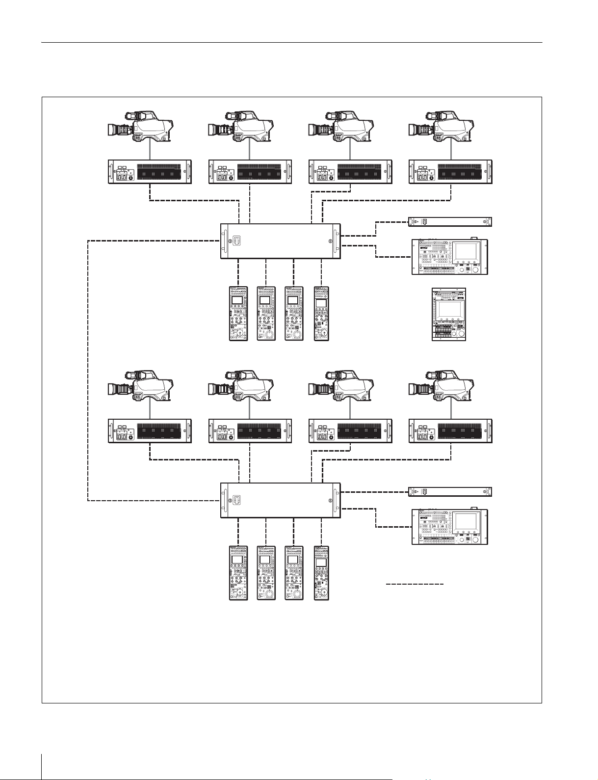
Examples of System Configurations
Connection example for LEGACY mode
Camera heads
CCU
CCU (1 to 6)
CNU-700
CCU/CNU
REMOTE
RCP (1 to 6)
RCP-1500/1501/1530
MSU-1000/1500
VCS
MSU
VCS-700
CCA-5 cable
• The maximum cable length for from a CCU (camera control unit) to an RCP is 200 m.
• Up to six systems can be connected to a CNU-700 as standard. In such a case, connect one MSU and one VCS.
Up to 12 systems can be connected if you install BKP-7930 in the CNU-700. In such a case, connect two MSUs and two
VCSs.
• Up to 24 systems can be connected if you connect a pair of CNU-700s. In such a case, you can connect four MSUs and
four VCSs, but ALL, RCP assignment, and master/subordinate cannot be executed for cameras connected to a different
CNU.
Overview
8
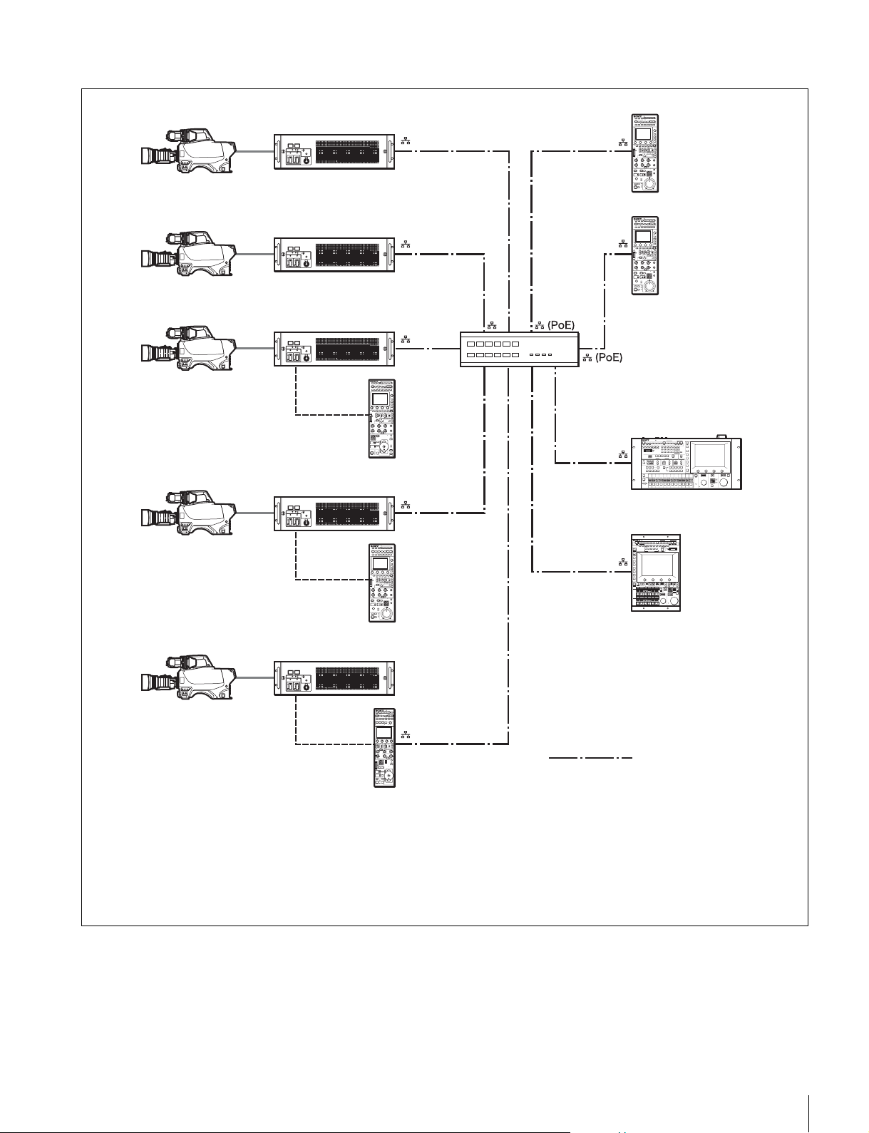
Connection example for MCS mode
Camera heads
CCU
PoE compatible switching hub
RCP-1500
MSU-1000/1500
RCP-1501
LAN straight cable
RCP-1530
(category 5 or above)
• In MCS mode, be sure to set one of the multiple MSUs as the master. Not to turn off the power or disconnect the cable of
the master MSU during operation.
• The maximum number of devices that can be directly connected to the network is 96 excluding the master MSU. This
maximum number does not include any RCP connected by CCA cable to a CCU connected to the network or any CCU
connected by CCA cable to a RCP connected to the network. A client MSU is counted as one unit.
• A CNU and VCS cannot be connected to a system that will be used in MCS mode.
Regarding the power supply of a switching hub
The power consumption of the PoE of this control panel is 7 W.
Use a hub capable of supplying enough power for all
connected RCPs.
Overview
9

Supported devices
Operating Cameras
This unit supports connection to the following devices.
• BVP-E30 series
• CCU-590/790 series
• HDC-1000(R)/1500(R)/3300(R) series
• HDCU-1000/1500/3300(R) series
• HSC-300/HSCU-300 series
• HXC-100/HXCU-100 series
• HDC-P1
• F23/F35
• SRW-9000
• PDW-700/740/F800
Notes
• Proper functioning may not be possible depending on the
firmware version. Be sure to update to the latest version
before use.
• The functions that are available on the control panel may be
limited depending on the connected camera. Some controls
may not function with certain cameras, but this is not a
malfunction.
Camera control permissions (panel active,
IRIS/MB active, and PARA)
By combining an MSU and RCP, you can operate one camera
device from multiple control panels, and multiple cameras from
one MSU. This is called a “multi-camera system.” A multicamera system can be implemented by introducing a CNU or
by establishing a LAN connection in MCS mode.
To prevent unintentional operation in a multi-camera system,
permission is granted to operate the cameras for only either
the connected MSU or RCP. There are three types of
permission.
• Panel active
Even if multiple control panels are connected to one camera,
only one control panel has the control permission. This
panel is referred to as “active.”
An inactive control panel can only be used to display the
status.
• PARA (parallel control)
By enabling the PARA function on an inactive control panel,
you can control cameras. The PARA function is enabled
from an inactive control panel, but can be disabled from any
control panel.
• IRIS/MB active
To prevent unintentional operation of IRIS and master black,
you can choose the control panels on which to activate
IRIS/MB. The PARA function does not operate.
Operating an inactive control panel on which PARA is
disabled will not change the state of the camera.
White balance link (master/subordinate mode)
The color temperature of light shining on the subject varies
moment by moment when you shoot outdoors. When
correcting for this, you can link the cameras within the system
and then control them. When you do this, set the camera that
is to be controlled directly to “Master,” and the cameras that
are to be linked to “Subordinate.”
When you change the white balance of the control panel to
which the master camera is connected, the subordinate
cameras are corrected by the same correction amount.
However, adjusting a subordinate camera does not affect any
of the other cameras.
The white balance link function is only enabled when there is
a connection to a CNU (LEGACY mode).
Note
The functions that are available on the control panel may be
limited depending on the connected camera. Some controls
may not function with certain cameras, but this is not a
malfunction.
10
Overview
Names and Functions of Parts
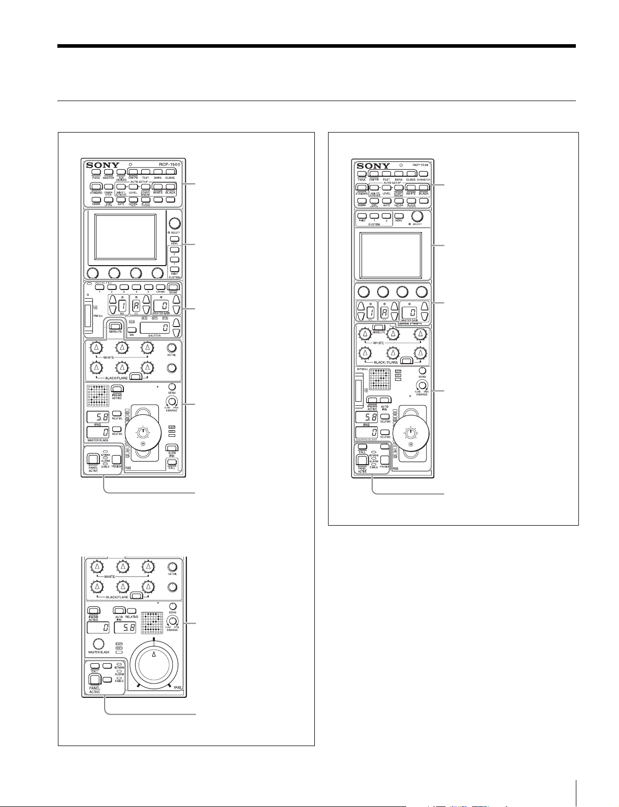
Operation Panel
RCP-1500
Camera/panel control block
(RCP-1500/1501) (page 12)
Menu operation block
(page 16)
Function control block
(RCP-1500/1501) (page 17)
Adjustment block (RCP-1500)
(page 20)
RCP-1530
Camera/panel control block
(RCP-1530) (page 14)
Menu operation block
(page 16)
Function control block
(RCP-1530) (page 19)
Adjustment block (RCP-1530)
(page 24)
RCP-1501
Panel control/status display
block (RCP-1500) (page 26)
Adjustment block (RCP-1501)
(page 22)
Panel control/status display
block (RCP-1501) (page 27)
Panel control/status display
block (RCP-1530) (page 28)
Names and Functions of Parts
11
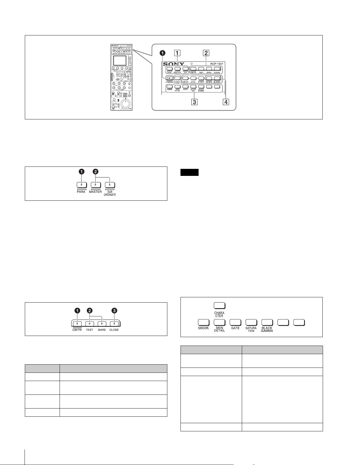
Camera/panel control block (RCP-1500/1501)
a STANDARD button
This button is for accessing the standard state of the camera.
After the standard state is accessed, you can cancel access by
pressing the STANDARD button again while it is lit.
1 Control selection block
a PARA (parallel control) button
This is the PARA function button. It allows you to
simultaneously control the control panels that are active.
However, IRIS and master black are only enabled on control
panels on which IRIS/MB is active, and cannot be controlled
simultaneously.
b MASTER and SUBORDINATE buttons
These are the master/subordinate function buttons. A
subordinate device is linked to the white balance adjustment
of the master device. If both are set to ON, the setting of the
master device takes priority.
These were formerly the master/slave function buttons.
2 Power/output signal selection block
b Test signal output selection buttons
These buttons light when pressed and are for operating the
test signal generator of the camera to output the
corresponding signal.
TEST: Camera test signal
BARS (color bars): Color bar signal
Note
When the BARS button is lit, the function of the BARS button
takes priority for CCU output. When you select TEST, press
the BARS button to turn its light off.
c CLOSE (iris close) button
This button is for closing the iris of the lens connected to the
camera. Pressing it when the auto iris is on changes the iris
indication to CLS. Pressing it when the auto iris is off displays
the iris value, and the state of that iris value is restored when
the close mode is cancelled.
3 Camera/CCU function ON/OFF buttons
These buttons are for various functions. A function is enabled
when its button is lit. A function with an OFF indication is off
when the button is lit. Functions can be assigned to the spare
buttons.
For details on assigning functions to spare buttons, see “To
assign functions to assignable buttons” (page 45).
a CAM PW (camera power) button
This button is for supplying power from the CCU to the camera
heads.
Lighting state Meaning
On The power is being supplied.
Off The power is disconnected. It is not supplied even
Slow flashing The power is disconnected. It is supplied when the
Fast flashing The camera is starting up.
Names and Functions of Parts
12
if the button is pressed.
button is pressed.
Button Description
5600K Electric color temperature correction
function
SKIN DETAIL Skin detail function
GATE Gate function
Displays the active area of the
function on the screen (corresponds
to Skin DTL and Multi matrix gate).
For details on for what kind of image
output a gate signal is displayed, refer
to the operation manual of the device
of the connection destination.
SATURATION Saturation function

Button Description
BLACK GAMMA Black gamma function
CHARACTER CCU character button
Turns ON/OFF character output of
the CCU and switches to the next
page. When this function is ON, each
press of the button switches to the
next page (holding the button
switches to the last page and stops
the function in the OFF state). For
details on for what kind of image
output characters are displayed, refer
to the operation manual of the device
of the connection destination.
4 AUTO SETUP block
These buttons are for automatically adjusting the camera.
a AUTO SETUP buttons and START/BREAK button
Pressing one of the following buttons and then pressing the
START/BREAK button runs the corresponding automatic
adjustment function.
SKIN DTL AUTO HUE: Automatically sets the skin detail to an
effective hue.
LEVEL: Runs the auto level setup.
Pressing the START/BREAK button while this function is
running stops auto adjustment. The button flashes to indicate
that this function is stopped, and pressing the button again
stops the flashing indication.
b WHITE (auto white balance) button
This button is for starting auto white balance adjustment. The
button is lit while this function is running and goes out when
adjustment is finished. Pressing it again or pressing the
START/BREAK button while this function is running stops
automatic adjustment. The button flashes to indicate that this
function is stopped, and pressing the button again stops the
flashing indication.
c BLACK (auto black balance) button
This button is for starting auto black balance adjustment. The
button is lit while this function is running and goes out when
adjustment is finished. Pressing it again or pressing the
START/BREAK button while this function is running stops
automatic adjustment. The button flashes to indicate that this
function is stopped, and pressing the button again stops the
flashing indication.
Names and Functions of Parts
13
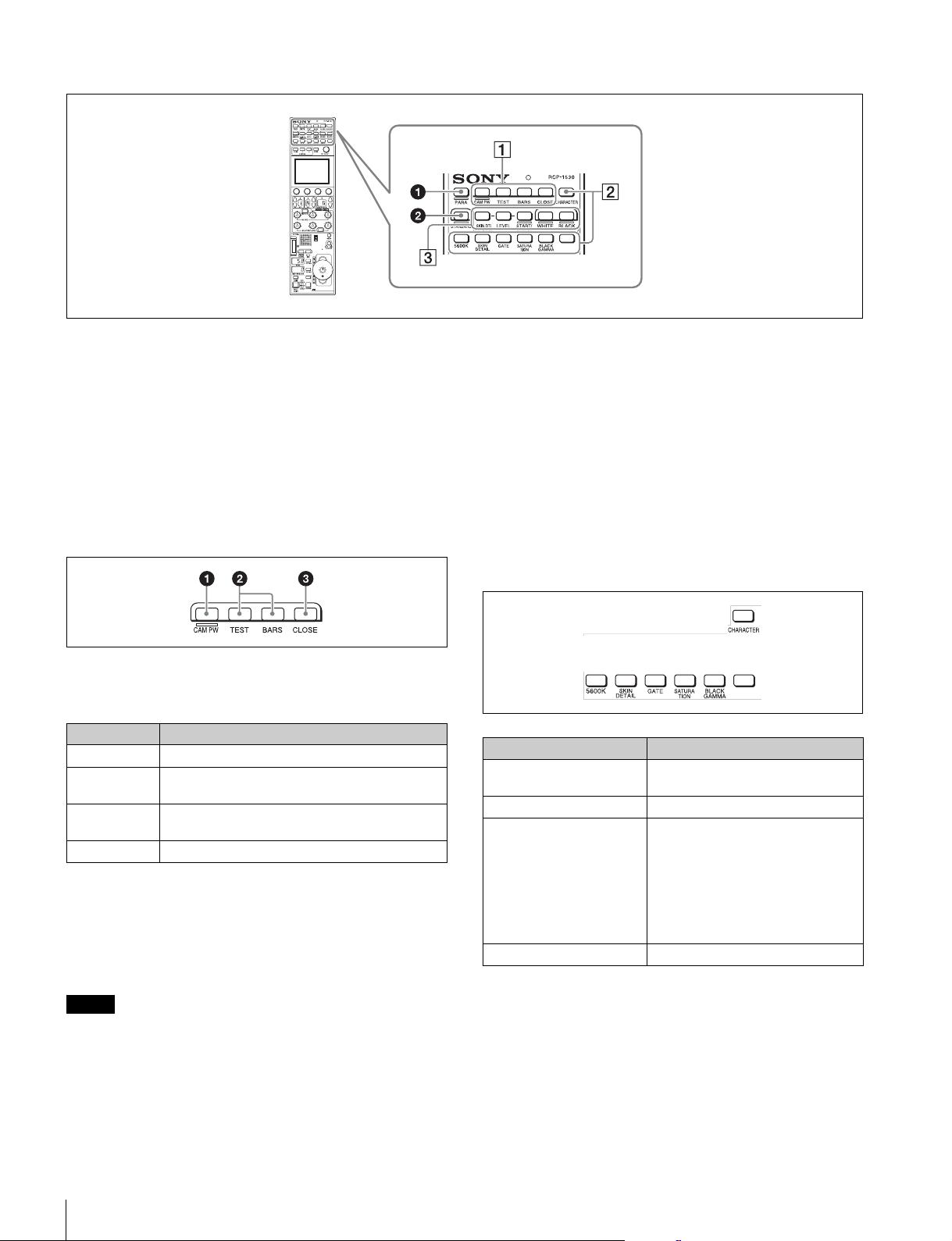
Camera/panel control block (RCP-1530)
a PARA (parallel control) button
This is the PARA function button. It allows you to
simultaneously control the control panels that are active.
However, IRIS and master black are only enabled on control
panels on which IRIS/MB is active, and cannot be controlled
simultaneously.
b STANDARD button
This button is for accessing the standard state of the camera.
After the standard state is accessed, you can cancel access by
pressing the STANDARD button again while it is lit.
1 Power/output signal selection block
a CAM PW (camera power) button
This button is for supplying power from the CCU to the camera
heads.
Lighting state Meaning
On The power is being supplied.
Off The power is disconnected. It is not supplied even
if the button is pressed.
Slow flashing The power is disconnected. It is supplied when the
button is pressed.
Fast flashing The camera is starting up.
b Test signal output selection buttons
These buttons light when pressed and are for operating the
test signal generator of the camera to output the
corresponding signal.
TEST: Camera test signal
BARS (color bars): Color bar signal
c CLOSE (iris close) button
This button is for closing the iris of the lens connected to the
camera. Pressing it when the auto iris is on changes the iris
indication to CLS. Pressing it when the auto iris is off displays
the iris value, and this value is redisplayed when the close
mode is cancelled.
2 Camera/CCU function ON/OFF buttons
These buttons are for various functions. A function is enabled
when its button is lit. A function with an OFF indication is off
when the button is lit. Functions can be assigned to the spare
buttons.
For details on assigning functions to spare buttons, see
page 45.
Button Description
5600K Electric color temperature correction
function
SKIN DETAIL Skin detail function
GATE Gate function
Displays the active area of the
function on the screen (corresponds
to Skin DTL and Multi matrix gate).
For details on for what kind of image
output a gate signal is displayed, refer
to the operation manual of the device
of the connection destination.
SATURATION Saturation function
Note
When the BARS button is lit, the function of the BARS button
takes priority. When you select TEST, press the BARS button
to turn its light off.
Names and Functions of Parts
14
Button Description
BLACK GAMMA Black gamma function
CHARACTER CCU character button
Turns ON/OFF character output of
the CCU and switches to the next
page. When this function is ON, each
press of the button switches to the
next page (a long press switches to
the last page and stops the function
in the OFF state). For details on for
what kind of image output characters
are displayed, refer to the operation
manual of the device of the
connection destination.
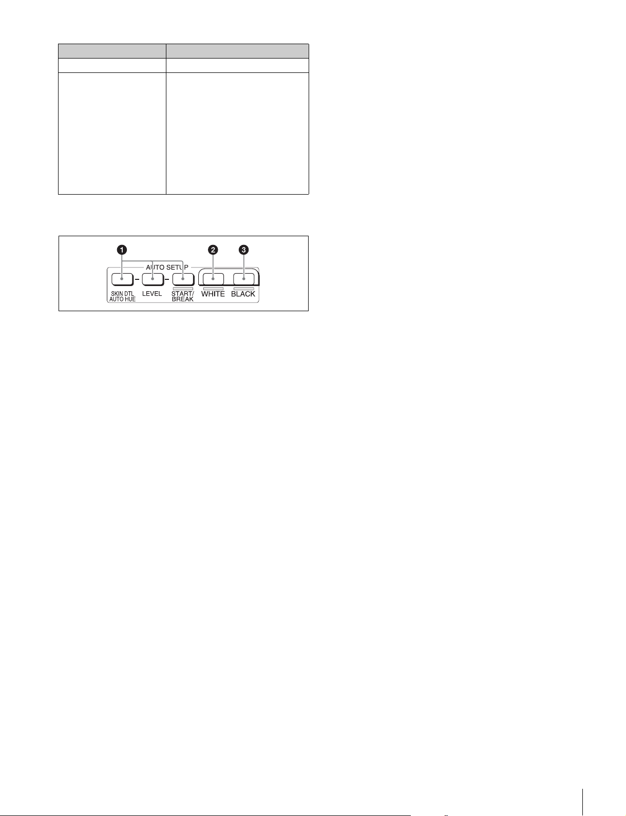
3 AUTO SETUP block
These buttons are for automatically adjusting the camera.
a AUTO SETUP buttons and START/BREAK button
Pressing one of the following buttons and then pressing the
START/BREAK button runs the corresponding automatic
adjustment function.
SKIN DTL AUTO HUE: Automatically sets the skin detail to an
effective hue.
LEVEL: Runs the auto level setup.
Pressing the START/BREAK button while this function is
running stops auto adjustment. The button flashes to indicate
that this function is stopped, and pressing the button again
stops the flashing indication.
b WHITE (auto white balance) button
This button is for starting auto white balance. The button is lit
while this function is running and goes out when adjustment is
finished. Pressing it again or pressing the START/BREAK
button while this function is running stops automatic
adjustment. The button flashes to indicate that this function is
stopped, and pressing the button again stops the flashing
indication.
c BLACK (auto black balance) button
This button is for starting auto black balance. The button is lit
while this function is running and goes out when adjustment is
finished. Pressing it again or pressing the START/BREAK
button while this function is running stops automatic
adjustment. The button flashes to indicate that this function is
stopped, and pressing the button again stops the flashing
indication.
Names and Functions of Parts
15
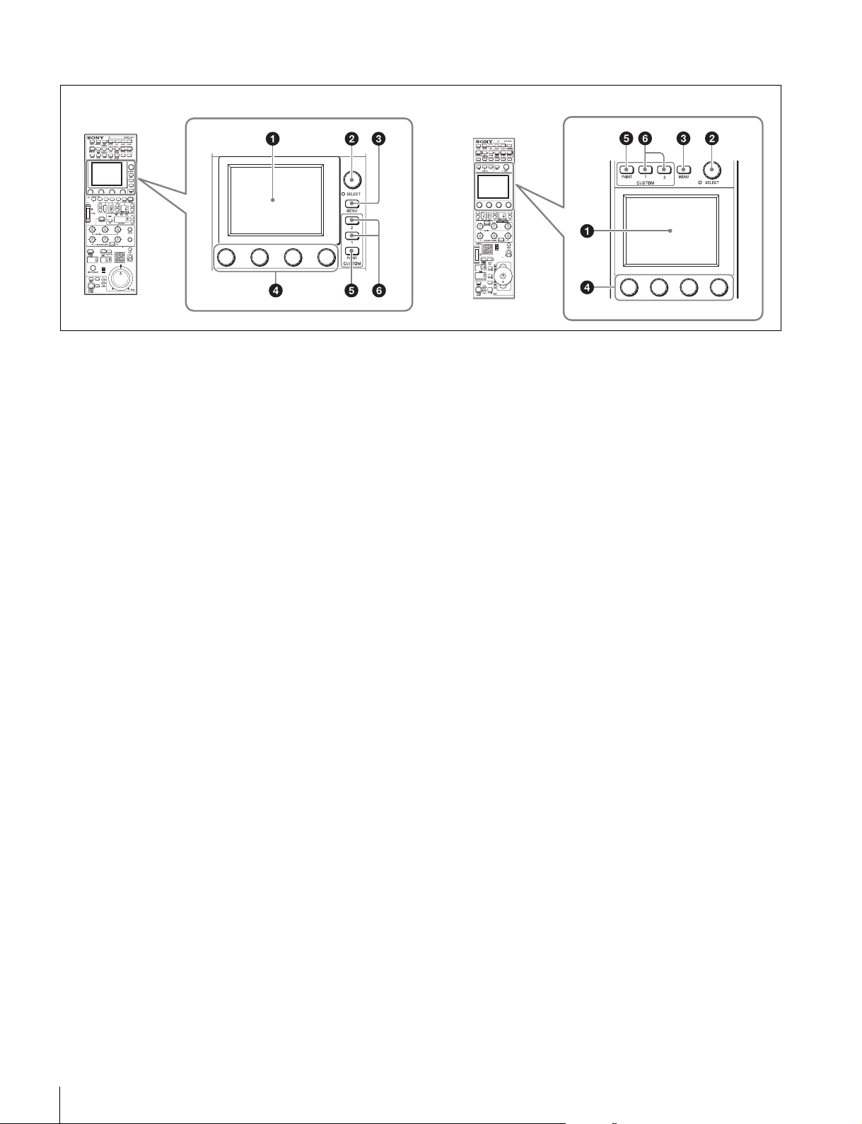
Menu operation block
RCP-1500/1501 RCP-1530
Menu operation is performed on the LCD.
Operation is performed by touching the buttons and tabs that
are displayed on the LCD. Use the adjustment knobs to
change numbers and select items.
To change menus, press a menu button or custom button and
then use the buttons in the menu to navigate through the
menu. When you reach the lowest level in the menu, the LED
of the SELECT knob lights. You can display the desired page
by turning the SELECT knob to forward through the menus in
order or by pressing the SELECT button and then accessing
the page from the selection screen.
For details on menu operations, see “Menu Tree” (page 53).
a LCD/touch panel
This is for displaying menus and performing operations.
b SELECT knob
Turning the knob while the LED is lit allows you to select
menus. Also, pressing in the knob allows you to switch to the
desired menu from the selection screen.
c MENU button
This button is for accessing the menu screen.
d Adjustment knobs (rotary encoders)
These knobs are for adjusting or selecting items in menus.
e CUSTOM PAINT button
This button is for accessing the CUSTOM PAINT menu. You
can set the contents and order of the CUSTOM PAINT menu.
f CUSTOM buttons
These buttons are for directly accessing preset menus. The
CUSTOM1 and CUSTOM2 buttons are available.
Names and Functions of Parts
16
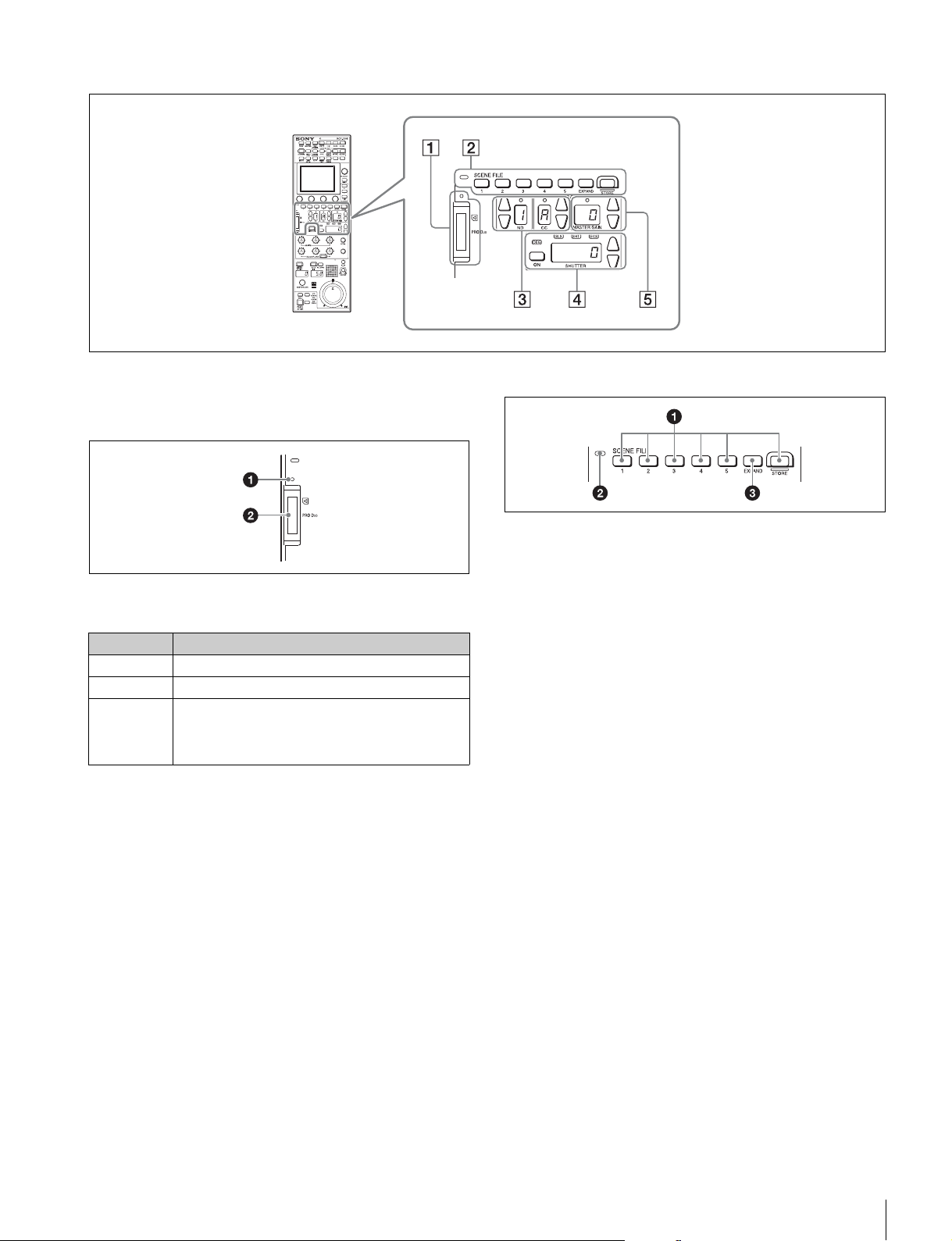
Function control block (RCP-1500/1501)
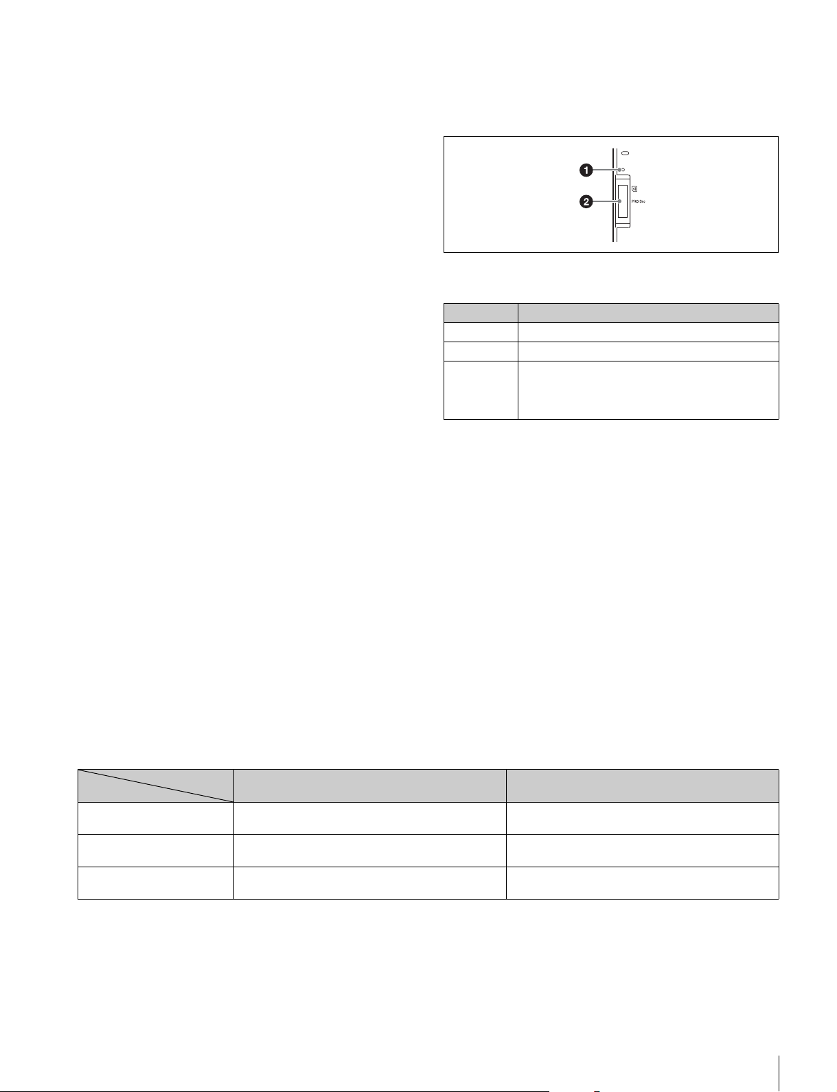
1 “Memory Stick Duo” insertion block
For details on a “Memory Stick Duo,” see “About “Memory
Stick Duo”” (page 79).
a Access indicator
This indicates the status of a “Memory Stick Duo.”
Indication Meaning or measure
Off A “Memory Stick Duo” is not inserted.
Lit in green A “Memory Stick Duo” is inserted.
Lit in red Data is being read or written. The data cannot be
guaranteed if you eject the “Memory Stick Duo” in
this state (be careful because all of the data may be
lost).
b “Memory Stick Duo” slot
This slot allows you to use a “Memory Stick Duo.” You can save
or read various files.
2 Scene file control block
a SCENE FILE selection buttons and STORE button
These buttons are for registering and reading scene files.
To register a scene file, press the STORE button to start it
flashing and then press the SCENE FILE button with the
corresponding number. When file registration is finished, the
STORE button goes out. To stop registration part way through,
press the STORE button again before pressing the SCENE
FILE button.
To read a scene file, press the SCENE FILE button with the
corresponding number while the STORE button is not flashing.
The items that can be stored to a scene file differ depending
on the connected camera.
b Scene file indicator
This lights when a scene file is read. While the any of scenes
1 to 5 is being read, the button with the corresponding number
is lit. While any of scenes 6 and above are read, only the LED
of SCENE FILE is lit.
c EXPAND button
This button is for accessing the Scene File menu to perform
various operations. Press this button to use the 32-scene file
function.
Names and Functions of Parts
17
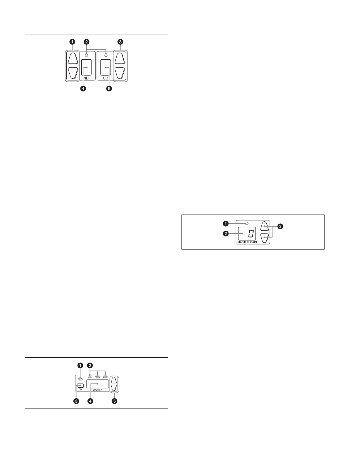
3 Filter control block
34 5
a ND filter selection buttons
These buttons are lit when the RCP has the filter servo control
permission. When they are not lit, the camera side has the
control permission. Pressing either the top or bottom button
once switches the control permission to the RCP. If there is no
filter servo or the camera does not have a filter, these buttons
do not light and the control permission can also not be
switched.
The v button changes the ND filters in order in the forward
direction. The V button changes them in the opposite
direction. Pressing and holding one of the buttons changes the
ND filters continuously.
b Standard value indicators
These light when standard values are set in the Standard Ind
menu. The indicators light in green when values are in their
standard state, and in amber when values are not in their
standard state.
a DEG indicator
This indicator is lit when the shutter display is indicating an
angle value. Configure the setting with the switches in Shutter
of the Paint menu.
b SLS/SHUTTER/ESC indicators
The indicator corresponding to the selected function is lit.
Select a function in the menu.
SLS: Slow shutter mode
SHT: Shutter mode
ECS: ECS (Extended Clear Scan) mode
c ON button
This button is for turning ON/OFF the camera’s SLS, shutter,
or ECS function. Pressing the button causes it to light and
turns ON the function, and pressing it again causes the button
to go out and turns OFF the function.
d Shutter speed display window
This window is for displaying the shutter speed that is currently
set. If the DEG indicator is lit while in shutter mode (the SHT
indicator is also lit), this window displays an angle value. If the
DEG indicator is not lit, the shutter speed is displayed in
seconds.
e Shutter speed selection buttons
These buttons are for setting the shutter speed. Each press of
the v (up) button increases the shutter speed, and each press
of the V (down) button decreases it.
5 Master gain control block
c CC (color temperature conversion) filter selection
buttons
These buttons are lit when the RCP has the filter servo control
permission. When they are not lit, the camera side has the
control permission. Pressing either the top or bottom button
once switches the control permission to the RCP. If there is no
filter servo or the camera does not have a filter, these buttons
do not light and the control permission can also not be
switched.
The v button changes the CC filters in order in the forward
direction. The V button changes them in the opposite
direction. Pressing and holding one of the buttons changes the
ND filters continuously.
d ND filter display window
This window displays the ND filter that is currently selected.
e CC (color temperature conversion) filter display
window
This window displays the CC filter that is currently selected.
4 Shutter control block
12
a Standard value indicator
This lights when standard values are set in the Standard Ind
menu. The indicator lights in green when values are in their
standard state, and in amber when values are not in their
standard state.
b Master gain display window
This window displays the master gain that is currently set.
c Master gain selection buttons
This block is for setting the sensitivity of the camera. Each
press of the v (up) button increases the sensitivity, and each
press of the V (down) button decreases it. Pressing and
holding one of the buttons changes the sensitivity
continuously. The setting value (unit: dB) is displayed in the
display window.
Names and Functions of Parts
18
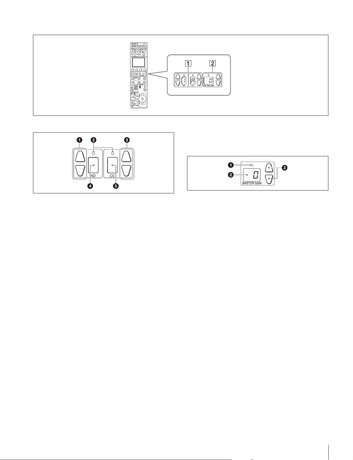
Function control block (RCP-1530)
1 Filter control block
a ND filter selection buttons
These buttons are lit when the RCP has the filter servo control
permission. When they are not lit, the camera side has the
control permission. Pressing either the top or bottom button
once switches the control permission to the RCP. If there is no
filter servo or the camera does not have a filter, these buttons
do not light and the control permission can also not be
switched.
The v button changes the ND filters in order in the forward
direction. The V button changes them in the opposite
direction. Pressing and holding one of the buttons changes the
ND filters continuously.
b Standard value indicators
These light when standard values are set in the Standard Ind
menu. The indicators light in green when values are in their
standard state, and in amber when values are not in their
standard state.
c CC (color temperature conversion) filter selection
buttons
These buttons are lit when the RCP has the filter servo control
permission. When they are not lit, the camera side has the
control permission. Pressing either the top or bottom button
once switches the control permission to the RCP. If there is no
filter servo or the camera does not have a filter, these buttons
do not light and the control permission can also not be
switched.
The v button changes the CC filters in order in the forward
direction. The V button changes them in the opposite
direction. Pressing and holding one of the buttons changes the
ND filters continuously.
e CC (color temperature conversion) filter display
window
This window displays the CC filter that is currently selected.
2 Master gain control block
a Standard value indicator
This lights when standard values are set in the Standard Ind
menu. The indicator lights in green when values are in their
standard state, and in amber when values are not in their
standard state.
b Master gain display window
This window displays the master gain that is currently set.
c Master gain selection buttons
This block is for setting the sensitivity of the camera. Each
press of the v (up) button increases the sensitivity, and each
press of the V (down) button decreases it. Pressing and
holding one of the buttons changes the sensitivity
continuously. The setting value (unit: dB) is displayed in the
displayed in the display window.
d ND filter display window
This window displays the ND filter that is currently selected.
Names and Functions of Parts
19
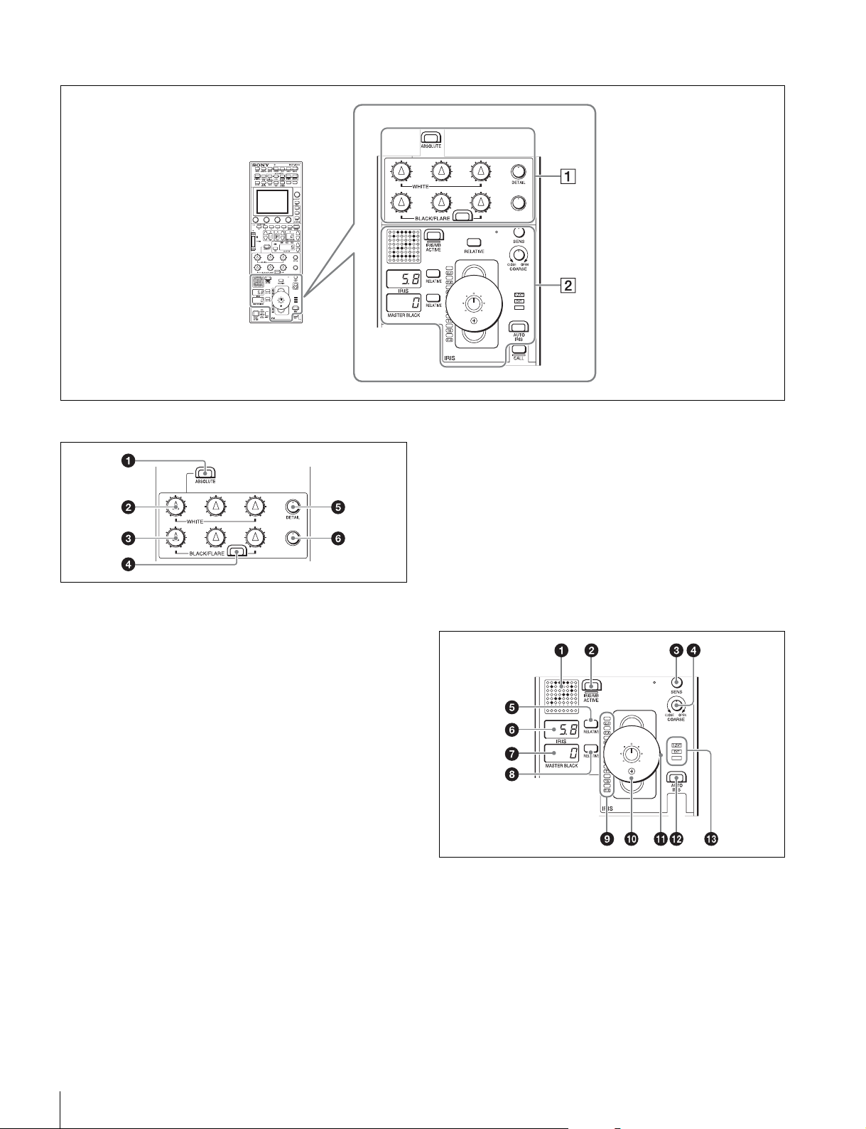
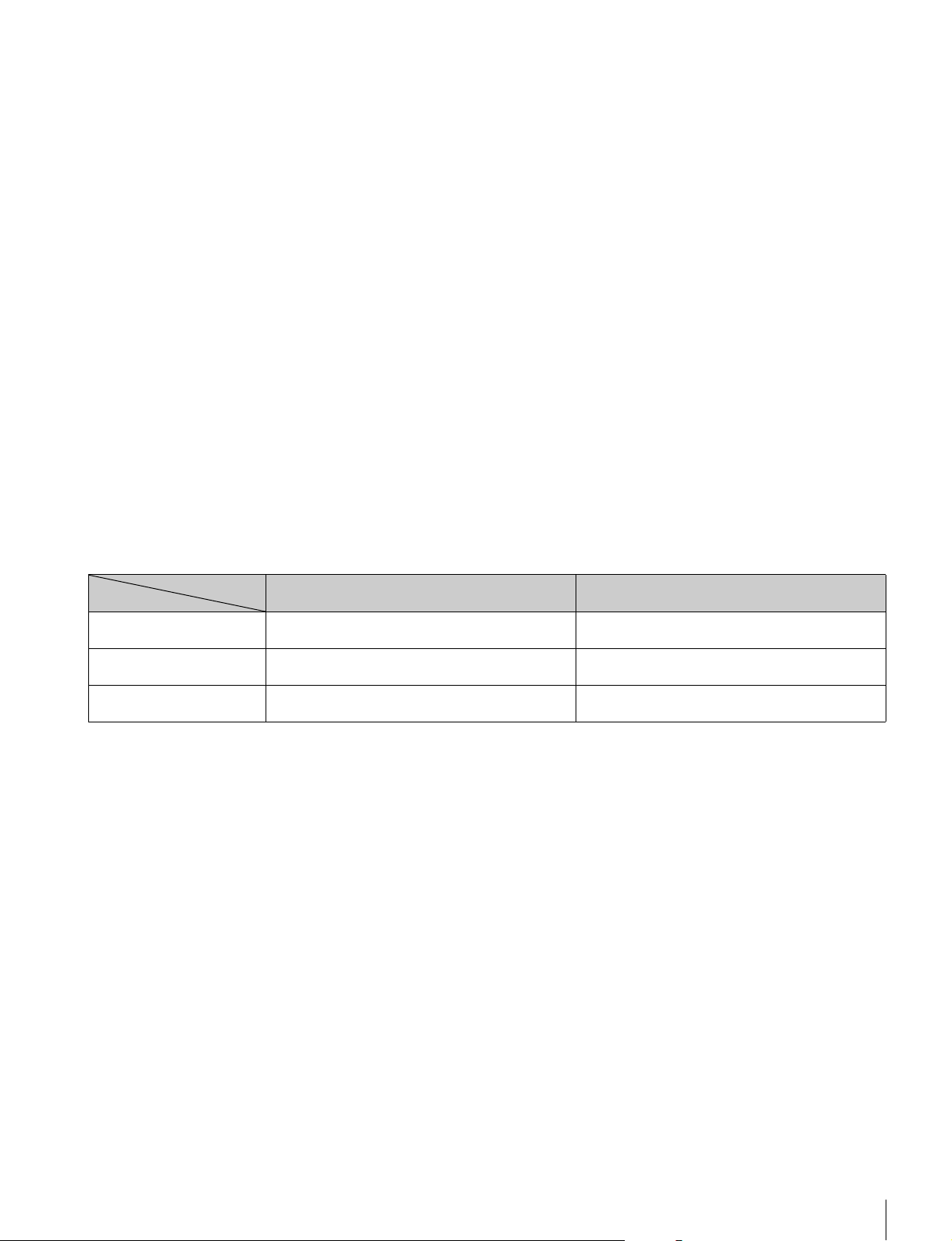
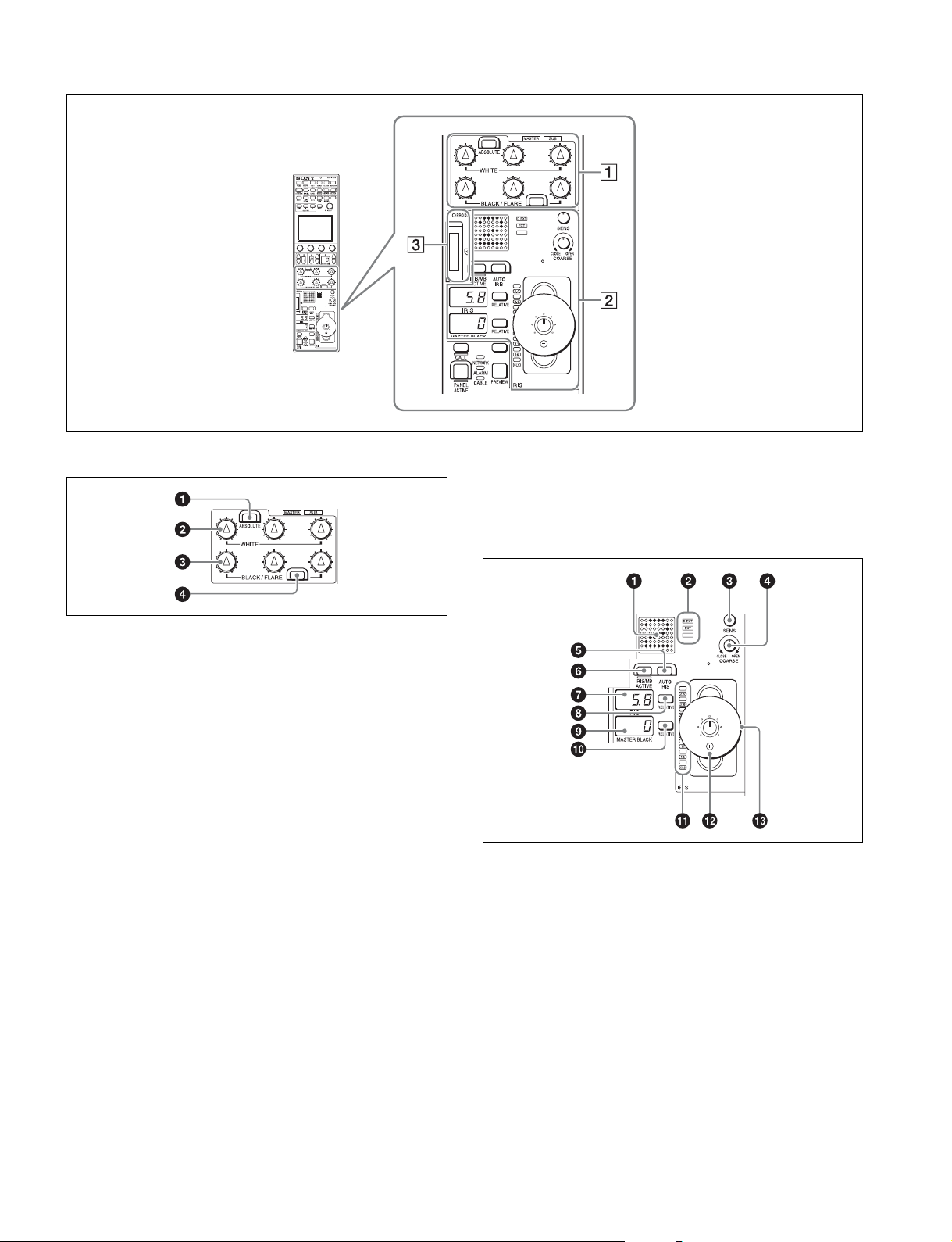
Adjustment block (RCP-1500)
1 White balance/black balance adjustment block
a ABSOLUTE button
This button changes the mode for manual adjustment using
the WHITE, BLACK, FLARE, DETAIL, and assignable knobs
between absolute value mode (lit) and relative value mode
(not lit). In absolute value mode, a knob indication value
becomes that setting value. In relative value mode, a knob
indication angle and the setting value do not match.
The relative value mode is selected automatically in the
following cases.
• During power up
• When the active status of the panel has changed
• When in PARA or master/subordinate mode
• When auto setup (level, white, and black) finishes
• When a scene file is read
• When the adjustment mode is switched between flare
balance and black balance by pressing the FLARE button
• When the controlled CCU/HDCU is changed with the RCP
Assign settings
b WHITE (manual white balance) knobs
These knobs allow you to adjust the R, G, and B signals in
order from left to right.
c BLACK/FLARE (manual black balance/flare balance)
knobs
These knobs adjust the black balance when the FLARE button
is not lit, and the flare balance when the FLARE button is lit.
They adjust the R, G, and B signals in order from left to right.
d FLARE (flare balance mode) button
This button changes the adjustment mode of the BLACK/
FLARE knobs. The knobs adjust the flare balance when the
button is lit, and the black balance when the button is not lit.
e DETAIL knob
This knob adjusts the detail level.
f Assignable adjustment knob
This knob adjusts a preselected item.
For details on selecting the item of the assignable adjustment
knob, see page 46.
2 Iris/master control black adjustment block
a Camera number/tally display window
This window displays an amber number for the camera
controlled by the control panel.
When a red tally signal is sent to the camera, a black number
is displayed and the background of the number lights in red.
When a green tally signal is sent to the camera, a black
number is displayed and the background of the number lights
in green.
When both red and green tally signals are simultaneously
sent, the left half of the background lights in red, and the right
half lights in green.
Names and Functions of Parts
20
b IRIS/MB ACTIVE (iris/master black active) button
This button is for the iris and master black control permission.
The iris and master black can only be adjusted when this
button is lit. Pressing the PANEL ACTIVE button also causes
this button to light.
c SENS (iris adjustment range) knob
This knob is for manually adjusting the iris in absolute value
mode. It does not work in relative value mode.
d COARSE (iris coarse adjustment) knob
This knob is for manually adjusting the iris.
Also see the table “Iris Adjustment Functions”, (page 23).
e IRIS RELATIVE button
This button changes the manual adjustment mode of the IRIS
control lever. Relative value mode is enabled when the button
is lit, and absolute value mode is enabled when the button is
not lit.
f IRIS display window
This window displays the iris setting as an F number. If the lens
is closed, “CLS” is displayed.
g Master black display window
This window displays the master black setting value.
h MASTER BLACK RELATIVE button
This button changes the manual adjustment mode of the
master black control ring. Relative value mode is enabled
when the button is lit, and absolute value mode is enabled
when the button is not lit.
i Iris indicators
The corresponding LED lights according to the iris setting.
When the IRIS RELATIVE button is not lit, the indicators light
dimly to display the upper and lower limits of manual
adjustment.
j IRIS control lever
This lever is for manually adjusting the iris of the lens when the
AUTO IRIS button is not lit. When the AUTO IRIS button is lit,
you can finely adjust the reference value for auto adjustment
of the iris.
Also see the table “Iris Adjustment Functions”, (page 23).
k Master black control ring
This ring is for manually adjusting the master black. The
setting value is displayed in the master black display window.
l AUTO IRIS button
This button is for adjusting the iris automatically.
m EXT (lens extender) indicators
EXT: Lights when the lens extender is used.
D EXT: Lights when the digital extender function is turned ON.
Iris Adjustment Functions
Relative value mode
(IRIS RELATIVE button lit)
IRIS knob Adjusts the iris in relative values.
A variable amount can be set. (See page 39)
COARSE knob Adjusts the iris in relative values within the full range
from OPEN to CLOSE.
SENS knob Does not function. Sets the upper limit for OPEN, referenced to the
Adjusts the iris within the variable range set by the
SENS and COARSE knobs.
Sets the lower limit for the CLOSE side.
CLOSE value set by the COARSE knob.
Absolute value mode
(IRIS RELATIVE button not lit)
Names and Functions of Parts
21
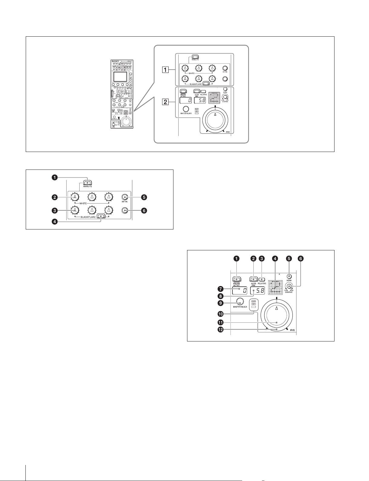
Adjustment block (RCP-1501)
1 White balance/black balance adjustment block
a ABSOLUTE button
This button changes the mode for manual adjustment using
the WHITE, BLACK, FLARE, DETAIL, and assignable knobs
between absolute value mode (lit) and relative value mode
(not lit). In absolute value mode, a knob indication value
becomes that setting value. In relative value mode, a knob
indication angle and the setting value do not match.
The relative value mode is selected automatically in the
following cases.
• During power up
• When the active status of the panel has changed
• When in PARA or master/subordinate mode
• When auto setup (level, white, and black) finishes
• When a scene file is read
• When the adjustment mode is switched between flare
balance and black balance by pressing the FLARE button
• When the controlled CCU/HDCU is changed with the RCP
Assign settings
b WHITE (manual white balance) knobs
These knobs allow you to adjust the R, G, and B signals in
order from left to right.
c BLACK/FLARE (manual black balance/flare balance)
knobs
These knobs adjust the black balance when the FLARE button
is not lit, and the flare balance when the FLARE button is lit.
They adjust the R, G, and B signals in order from left to right.
d FLARE (flare balance mode) button
This button changes the adjustment mode of the BLACK/
FLARE knobs. The knobs adjust the flare balance when the
button is lit, and the black balance when the button is not lit.
e DETAIL knob
This knob adjusts the detail level.
f Assignable adjustment knob
This knob adjusts a preselected item.
For details on selecting the item of the assignable adjustment
knob, see page 46.
2 Iris/master control black adjustment block
a IRIS/MB ACTIVE (iris/master black active) button
This button is for the iris and master black control permission.
The iris and master black can only be adjusted when this
button is lit. Pressing the PANEL ACTIVE button also causes
this button to light.
b AUTO IRIS button
This button is for adjusting the iris automatically.
c IRIS RELATIVE button
This button changes the manual adjustment mode of the IRIS
knob. Relative value mode is enabled when the button is lit,
and absolute value mode is enabled when the button is not lit.
Names and Functions of Parts
22
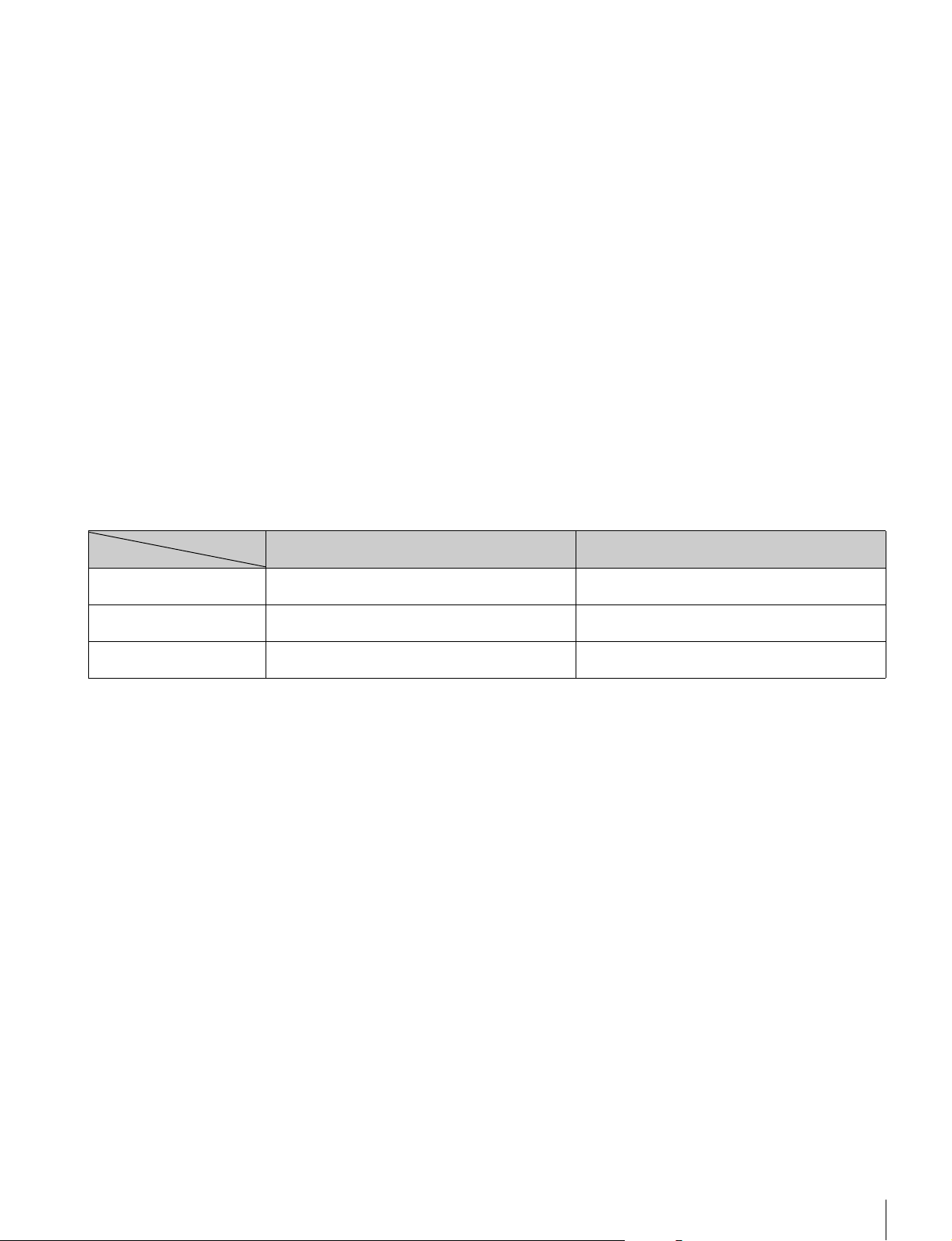
d Camera number/tally display window
This window displays an amber number for the camera
controlled by the control panel.
When a red tally signal is sent to the camera, a black number
is displayed and the background of the number lights in red.
When a green tally signal is sent to the camera, a black
number is displayed and the background of the number lights
in green.
When both red and green tally signals are simultaneously
sent, the left half of the background lights in red, and the right
half lights in green.
e SENS (iris adjustment range) knob
This knob is for manually adjusting the iris in absolute value
mode. It does not work in relative value mode.
f COARSE (iris coarse adjustment) knob
This knob is for manually adjusting the iris.
Also see the table “Iris Adjustment Functions”, (page 23).
g Master black display window
This window displays the master black setting value.
h IRIS display window
This window displays the iris setting as an F number. If the lens
is closed, “CLS” is displayed.
Iris Adjustment Functions
i MASTER BLACK knob
This knob is for manually adjusting the master black. The
setting value is displayed in the master black display window.
j EXT (lens extender) indicators
EXT: Lights when the lens extender is used.
D EXT: Lights when the digital extender function is turned ON.
k IRIS knob
This knob is for manually adjusting the iris of the lens when the
AUTO button is not lit. When the AUTO IRIS button is lit, you
can finely adjust the reference value for auto adjustment of the
iris.
Also see the table “Iris Adjustment Functions”, (page 23).
l Iris gauge
The white marker line on the gauge provides a click position
for the IRIS knob. If you turn the gauge to align the marker line
with the most frequently used iris position, it can be used as a
setting reference for the IRIS knob.
The gauge rotates 360, so set the marker line so that it is
outside the rotation range of the knob if you do not need a click
position.
Relative value mode
(IRIS RELATIVE button lit)
IRIS knob Adjusts the iris in relative values.
A variable amount can be set. (See page 39)
COARSE knob Adjusts the iris in relative values within the full range
from OPEN to CLOSE.
SENS knob Does not function. Sets the upper limit for OPEN, referenced to the
Adjusts the iris within the variable range set by the
SENS and COARSE knobs.
Sets the lower limit for the CLOSE side.
CLOSE value set by the COARSE knob.
Absolute value mode
(IRIS RELATIVE button not lit)
Names and Functions of Parts
23
Adjustment block (RCP-1530)
1 White balance/black balance adjustment block
a ABSOLUTE button
This button changes the mode for manual adjustment using
the WHITE, BLACK, FLARE, DETAIL, and assignable knobs
between absolute value mode (lit) and relative value mode
(not lit). In absolute value mode, a knob indication value
becomes that setting value. In relative value mode, a knob
indication angle and the setting value do not match.
The relative value mode is selected automatically in the
following cases.
• During power up
• When the active status of the panel has changed
• When in PARA or master/subordinate mode
• When auto setup (level, white, and black) finishes
• When a scene file is read
• When the adjustment mode is switched between flare
balance and black balance by pressing the FLARE button
• When the controlled CCU/HDCU is changed with the RCP
Assign settings
b WHITE (manual white balance) knobs
These knobs allow you to adjust the R, G, and B signals in
order from left to right.
c BLACK/FLARE (manual black balance/flare balance)
knobs
These knobs adjust the black balance when the FLARE button
is not lit, and the flare balance when the FLARE button is lit.
They adjust the R, G, and B signals in order from left to right.
d FLARE (flare balance mode) button
This button changes the adjustment mode of the BLACK/
FLARE knobs. The knobs adjust the flare balance when the
button is lit, and the black balance when the button is not lit.
2 Iris/master control black adjustment block
a Camera number/tally display window
This window displays an amber number for the camera
controlled by the control panel.
When a red tally signal is sent to the camera, a black number
is displayed and the background of the number lights in red.
When a green tally signal is sent to the camera, a black
number is displayed and the background of the number lights
in green.
When both red and green tally signals are simultaneously
sent, the left half of the background lights in red, and the right
half lights in green.
b EXT (lens extender) indicators
EXT: Lights when the lens extender is used.
D EXT: Lights when the digital extender function is turned ON.
Names and Functions of Parts
24
c SENS (iris adjustment range) knob
This knob is for manually adjusting the iris in absolute value
mode. It does not work in relative value mode.
m Master black control ring
This ring is for manually adjusting the master black. The
setting value is displayed in the master black display window.
d COARSE (iris coarse adjustment) knob
This knob is for manually adjusting the iris.
Also see the table “Iris Adjustment Functions”, (page 23).
e AUTO IRIS button
This button is for adjusting the iris automatically.
f IRIS/MB ACTIVE (iris/master black active) button
This button is for the iris and master black control permission.
The iris and master black can only be adjusted when this
button is lit. Pressing the PANEL ACTIVE button also causes
this button to light.
g IRIS display window
This window displays the iris setting as an F number. If the lens
is closed, “CLS” is displayed.
h IRIS RELATIVE button
This button changes the manual adjustment mode of the IRIS
control lever. Relative value mode is enabled when the button
is lit, and absolute value mode is enabled when the button is
not lit.
i Master black display window
This window displays the master black setting value.
j MASTER BLACK RELATIVE button
This button changes the manual adjustment mode of the
master black control ring. Relative value mode is enabled
when the button is lit, and absolute value mode is enabled
when the button is not lit.
3 “Memory Stick Duo” insertion block
a Access indicator
This indicates the status of a “Memory Stick Duo.”
Indication Meaning or measure
Off A “Memory Stick Duo” is not inserted.
Lit in green A “Memory Stick Duo” is inserted.
Lit in red Data is being read or written. The data cannot be
guaranteed if you eject the “Memory Stick Duo” in
this state (be careful because all of the data may be
lost).
b “Memory Stick Duo” slot
This slot allows you to use a “Memory Stick Duo.” You can save
or read various files.
For details on handling a “Memory Stick Duo,” see “About
“Memory Stick Duo”” (page 79).
k Iris indicators
The corresponding LED lights according to the iris setting.
When the IRIS RELATIVE button is not lit, the indicators light
dimly to display the upper and lower limits of manual
adjustment.
l IRIS control lever
This lever is for manually adjusting the iris of the lens when the
AUTO IRIS button is not lit. When the AUTO IRIS button is lit,
you can finely adjust the reference value for auto adjustment
of the iris.
Also see the table “Iris Adjustment Functions”, (page 25).
Iris Adjustment Functions
Relative value mode
(IRIS RELATIVE button lit)
IRIS knob Adjusts the iris in relative values.
A variable amount can be set. (See page 39)
COARSE knob Adjusts the iris in relative values within the full range
from OPEN to CLOSE.
SENS knob Does not function. Sets the upper limit for OPEN, referenced to the
Adjusts the iris within the variable range set by the
SENS and COARSE knobs.
Sets the lower limit for the CLOSE side.
CLOSE value set by the COARSE knob.
Absolute value mode
(IRIS RELATIVE button not lit)
Names and Functions of Parts
25
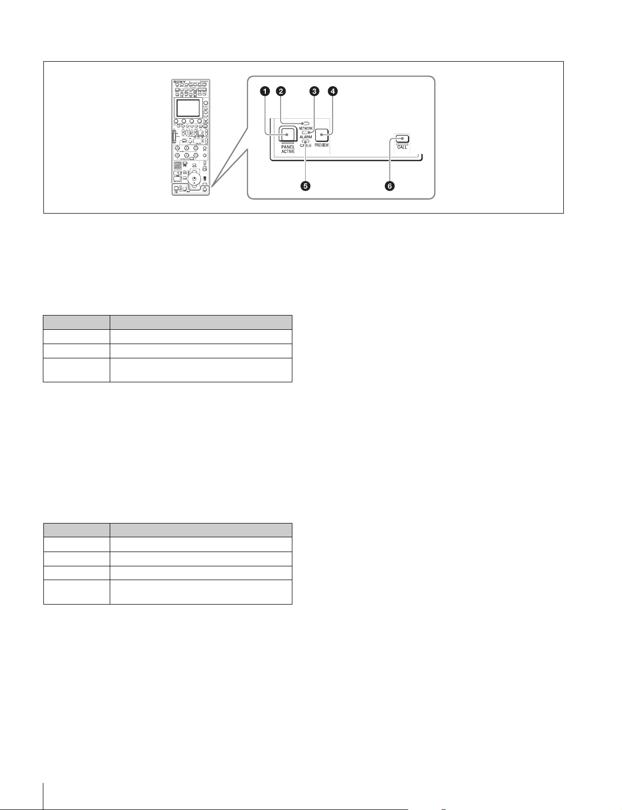
Panel control/status display block (RCP-1500)
a PANEL ACTIVE button
This button is for the control permission. It also serves as a
function for preventing unintentional operation because a
camera cannot be controlled from this control panel when this
button and the PARA button are not lit.
b NETWORK indicator
This indicates the status of the network connection.
Lighting state Meaning
On Connected to a control device.
Flashing A control device cannot be found.
Off Cannot connect to the camera network.
Alternatively, the mode is LEGACY.
c ALARM indicator
This lights red when a system error occurs and the selfdiagnosis function is operating on the camera head or CCU/
HDCU.
d PREVIEW button
This button is for outputting preview key signals from the EXT
I/O connector.
e CABLE indicator
This indicates the communication state of the camera head
and CCU.
Lighting state Meaning
On (green) The reception state is good.
On (yellow) The reception level is low.
On (red) The reception level is extremely low.
Off The power of the camera is off. Alternatively, a
communication error occurred.
f CALL button
This button is for communication. If it is pressed, the tally state
for the camera or CCU changes, and a call signal is sent.
Likewise, a call signal can be received from another device.
When a call signal is sent (or received), this button lights and
the call sound plays. The call sound can be selected in the
menu.
Names and Functions of Parts
26
 Loading...