

Sony RCP-1001, RCP-1000 Operation Manual

REMOTE CONTROL PANEL
RCP-1000
RCP-1001
OPERATION MANUAL [English]
1st Edition (Revised 3)

Table of Contents
Precautions
Precautions................................................................ 2
Overview .................................................................... 3
Features .......................................................................... 3
Examples of System Configurations ............................... 4
Supported devices .......................................................... 6
Operating Cameras ........................................................ 6
Names and Functions of Parts ................................ 7
Operation Panel .............................................................. 7
Connector Panel ........................................................... 12
Settings .................................................................... 13
Setting the Control Panel .............................................. 13
Adjusting the Brightness of the LED ............................. 13
Setting Display Characters to Light-up in Dark
Locations ................................................................... 13
To set the brightness of display characters when they
are unlit ................................................................ 13
Adjusting the Click Sound Level of the Buttons ............ 14
Setting the Call Sound .................................................. 14
Setting Functions to Assign to the DETAIL Knob ......... 14
Initializing Settings ........................................................14
Assigning Functions to the Assignable Button .............. 15
Specifications .......................................................... 15
Note on interference
Do not place mobile phones or similar devices on the control
panel. Doing so may result in malfunction of the unit.
Precautions / Precautions
2

Overview
Features
The MSU-1000 series and RCP-1000 series are remote
control panels for configuring and controlling Sony’s studio
and broadcast cameras.
This section describes the features that are common between
the MSU-1000 series and RCP-1000 series.
Remote control panels
The RCP-1000 series of remote control panels is designed
mainly for operation. Use a remote control panel with a camera
on a one-to-one basis.
• The RCP-1000 is a compact control panel with specialized
basic operations. The iris and master black adjustment block
employs joystick type control. Up to six units can be
mounted in a 19-inch EIA rack.
• The RCP-1001 is a compact control panel with specialized
basic operations. The iris and master black adjustment block
employs dial (knob) type control. Up to six units can be
mounted in a 19-inch EIA rack.
Operability suitable for basic camera
operations
This remote control panel is provided with the control functions
required to perform the basic operations of cameras to enable
the simple and accurate operation of various functions. The
operation buttons, adjustment knobs, and other controls are
arranged on the panel according to function and frequency of
use. Guard frames are provided around buttons that are vital
to the operation and setup of cameras to prevent the buttons
from being unintentionally operated.
Illuminated buttons with high visibility flash and light to notify
you of the operation status to enable operation even in dark
locations. Likewise, an illuminated panel surface is employed
to allow you to confirm function names even when the
surroundings are dark.
Support for operating multiple cameras
Various operations are made possible by using multiple
camera systems that support multiple cameras.
The following functions are provided to control the connected
cameras.
• Panel active function
This function always enables one control panel for one
camera to prevent unintentional operation. Even with a
control panel that does not have the panel active
permission, a camera can be operated using the parallel
function, with the exception of iris and master black
operations.
• ALL function
This function simultaneously turns on and off the functions
of all connected camera systems.
• RCP assignment function
This function changes the combination of an RCP and
camera system.
• Master/subordinate function
This function makes changes in conjunction with the color
temperature of the specified camera system.
1)
1)
1) 2) 3)
Customizable functions
Various settings can be configured according to the operation
configuration and the frequency with which functions are used.
•Switches
You can assign any function to a spare switch.
• Operation and call sounds
You can mute and adjust the volume of the operation and
call sounds if necessary.
1) If multiple CNUs exist in the system, this only works for cameras
connected to the same CNU.
2) This does not work when connected to a network.
3) This unit does not include a master/subordinate switching
mechanism. Switching between master and subordinate mode
must be performed from another control panel.
Building of a variety of control systems
You can build a multi-camera control system through use of
the CNU-700. In a system that uses CNU-700s, two CNUs can
be used to control a camera system of up to 24 cameras. A
system that uses a LAN can also be built by connecting to a
LAN-compatible CCU.
Overview
3
Examples of System Configurations
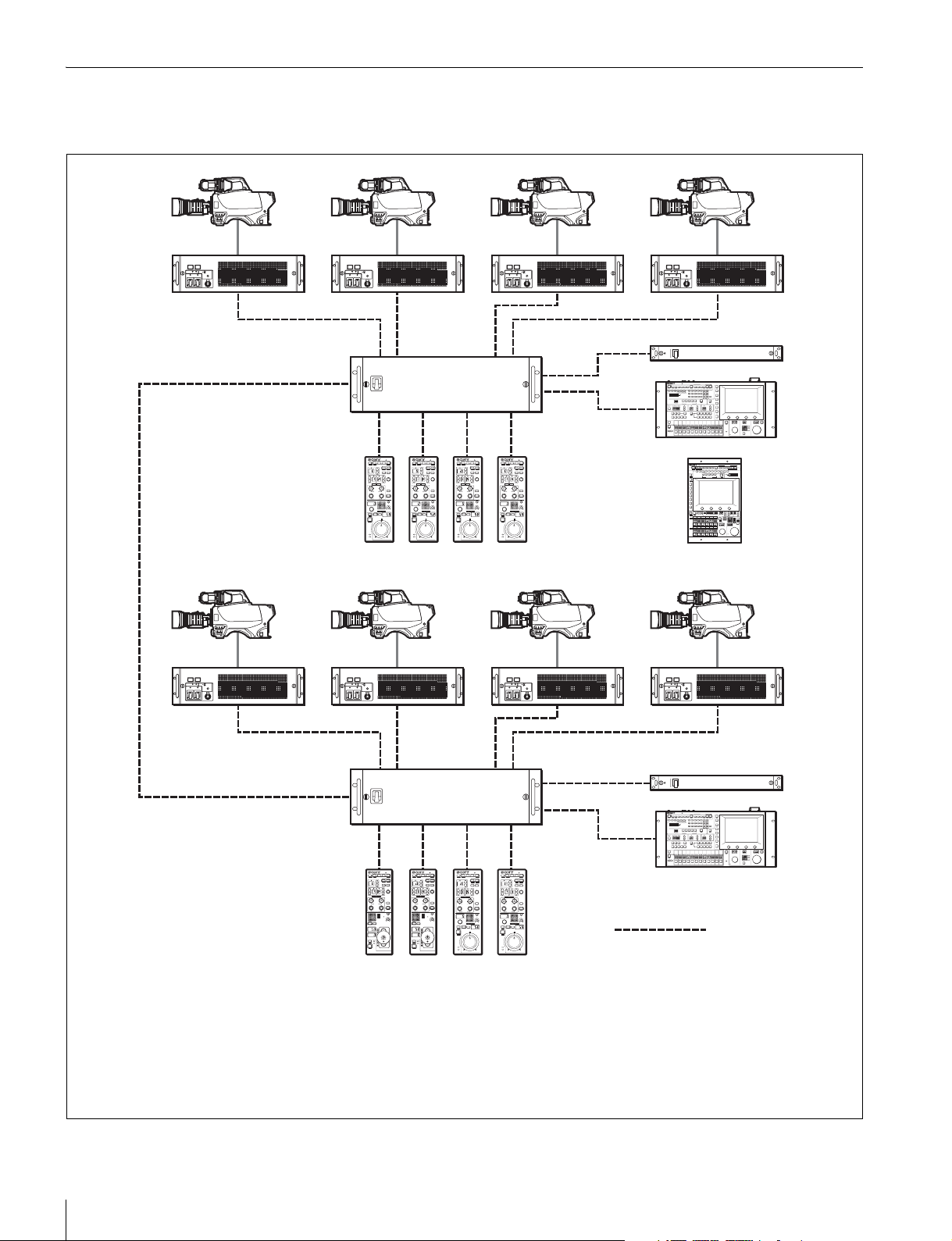
Connection example for LEGACY mode
Camera heads
CCU
CCU (1 to 6)
CNU-700
CCU/CNU
REMOTE
RCP (1 to 6)
RCP-1000/1001
VCS
MSU
MSU-1000/1500
VCS-700
CCA-5 cable
• The maximum cable length for from a CCU (camera control unit) to an RCP is 200 m.
• Up to six systems can be connected to a CNU-700 as standard. In such a case, connect one MSU and one VCS.
Up to 12 systems can be connected if you install BKP-7930 in the CNU-700. In such a case, connect two MSUs and two
VCSs.
• Up to 24 systems can be connected if you connect a pair of CNU-700s. In such a case, you can connect four MSUs and
four VCSs, but ALL, RCP assignment, and master/subordinate cannot be executed for cameras connected to a different
CNU.
Overview
4
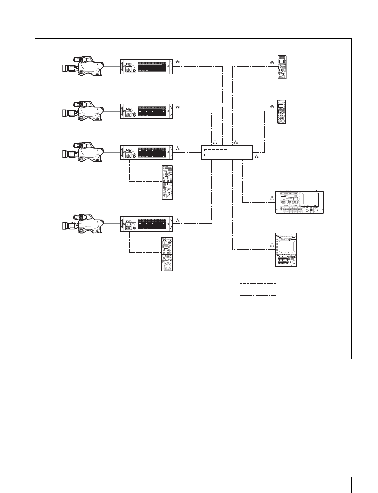
Connection example for MCS mode
Camera heads
CCU
RCP-1000
MSU-1000/1500
RCP-1001
CCA-5 cable
LAN straight cable
(category 5 or above)
• In MCS mode, be sure to set one of the multiple MSUs as the master. Not to turn off the power or disconnect the cable of
the master MSU during operation.
• The maximum number of devices that can be directly connected to the network is 96 excluding the master MSU. This
maximum number does not include any RCP connected by CCA cable to a CCU connected to the network or any CCU
connected by CCA cable to a RCP connected to the network. A client MSU is counted as one unit.
• A CNU and VCS cannot be connected to a system that will be used in MCS mode.
Overview
5

Supported devices
Operating Cameras
This unit supports connection to the following devices.
• BVP-E30 series
• CCU-590/790 series
• HDC-1000(R)/1500(R)/3300(R) series
• HDCU-1000/1500/3300(R) series
• HSC-300/HSCU-300 series
• HXC-100/HXCU-100 series
• HDC-P1
• F23/F35
• SRW-9000
• PDW-700/740/F800
• HSC300RF/300R/100RF/100R
• HSCU300RF/300R
•CA4000
• BPU8000/4000
Notes
• Proper functioning may not be possible depending on the
firmware version. Be sure to update to the latest version
before use.
• The functions that are available on the control panel may be
limited depending on the connected camera. Some controls
may not function with certain cameras, but this is not a
malfunction.
Camera control permissions (panel active,
IRIS/MB active, and PARA)
By combining an MSU and RCP, you can operate one camera
device from multiple control panels, and multiple cameras from
one MSU. This is called a “multi-camera system.” A multicamera system can be implemented by introducing a CNU or
by establishing a LAN connection in MCS mode.
To prevent unintentional operation in a multi-camera system,
permission is granted to operate the cameras for only either
the connected MSU or RCP. There are three types of
permission.
• Panel active
Even if multiple control panels are connected to one camera,
only one control panel has the control permission. This
panel is referred to as “active.”
An inactive control panel can only be used to display the
status.
• PARA (parallel control)
By enabling the PARA function on an inactive control panel,
you can control cameras. The PARA function is enabled
from an inactive control panel, but can be disabled from any
control panel.
• IRIS/MB active
To prevent unintentional operation of IRIS and master black,
you can choose the control panels on which to activate
IRIS/MB. The PARA function does not operate.
Operating an inactive control panel on which PARA is
disabled will not change the state of the camera.
White balance link (master/subordinate mode)
The color temperature of light shining on the subject varies
moment by moment when you shoot outdoors. When
correcting for this, you can link the cameras within the system
and then control them. When you do this, set the camera that
is to be controlled directly to “Master,” and the cameras that
are to be linked to “Subordinate.”
When you change the white balance of the control panel to
which the master camera is connected, the subordinate
cameras are corrected by the same correction amount.
However, adjusting a subordinate camera does not affect any
of the other cameras.
The white balance link function is only enabled when there is
a connection to a CNU (LEGACY mode).
Note
The functions that are available on the control panel may be
limited depending on the connected camera. Some controls
may not function with certain cameras, but this is not a
malfunction.
6
Overview
 Loading...