

Page 1
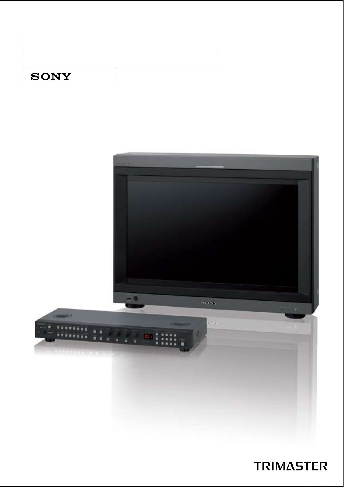
PVM-L2300 Trimaster Monitor.
LCD Broadcast Monitor
Page 2
Contents
4 > Main Features
9 > Operational convenience
15 > Easy setup and adjustment
15 > Other Features
16 > Specifications
18 > Dimensions
19 > Optional Accessories
2
Page 3
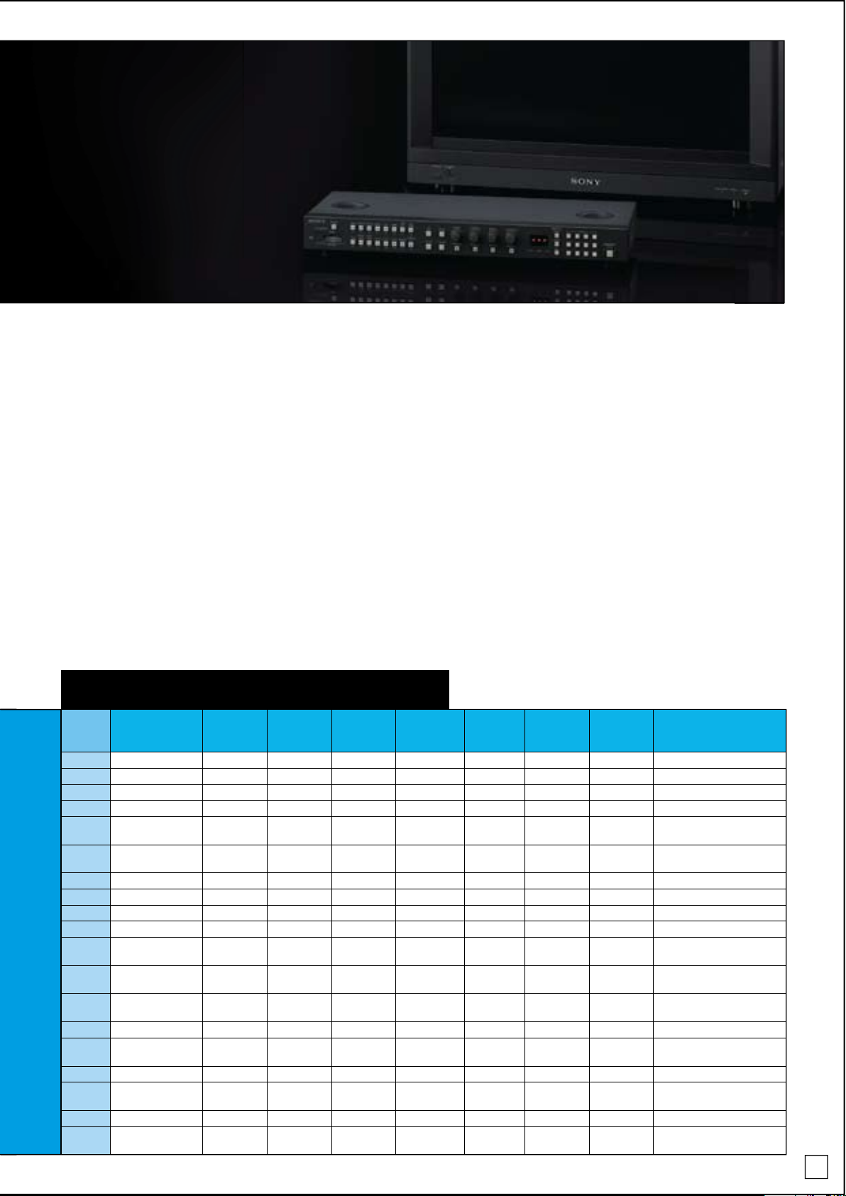
PVM-L2300
Sony Extends its TRIMASTER Series With the PVM-L2300 TRIMASTER
Broadcast Monitor
Since its introduction in 2006, Sony’s TRIMASTER™ technology
has been widely adopted for high-end picture-monitoring
applications, and acclaimed for its high picture quality,
operability, and reliability. Sony now introduces a new
TRIMASTER monitor for broadcast applications.
The PVM-L2300 is a 23-inch1 LCD
monitor with a customized WCG-CCFL
(Wide Colour Gamut CCFL) backlight
system designed for use in broadcast
applications. Built on the TRIMASTER
design concept, the PVM-L2300
monitor can reproduce images
consistent with the BVM-L231 TRIMASTER
master monitor. By incorporating the
same processing-engine technology
of the BVM-L231 master monitor, the
PVM-L2300 offers the superb picture
performance and sophisticated
features required by today’s broadcast
and critical picture-monitoring
applications. Also, the
PVM-L2300 can accept almost any
type of video and PC signal, both
analog and digital. The video interface
accepts analog composite signals up
2
to 3G SDI
signals from VGA to WUXGA.
, as well as HDMI™ and DVI
In addition, the PVM-L2300 offers great
affinity between Sony’s professional
CRT monitors in terms of system
configuration, installation, physical
size, functionality, and operational
convenience.
The PVM-L2300 is the ideal choice
for the next level of digital broadcast
system that requires smooth migration
– from CRT to LCD, SD to HD, and/or
interlace to progressive.
1 22.5-inch viewable area measured diagonally.
2 The optional BKM-250TG board is required.
3
Page 4
The PVM-L2300 incorporates the professional display engine used in Sony’s BVM-L231 master
monitor. In addition, it also features a unique high-grade 23-inch
1
full resolution LCD panel and a
high-quality WCG-CCFL (Wide Colour Gamut CCFL) backlight system. What is great about the
PVM-L2300 monitor is that it conforms to broadcast-standard colour gamuts unlike some wide
CCFL backlight system LCD monitors. As a result of all this, the PVM-L2300 offers a high level of
picture quality, accuracy, and reliability.
1 22.5-inch viewable area measured diagonally.
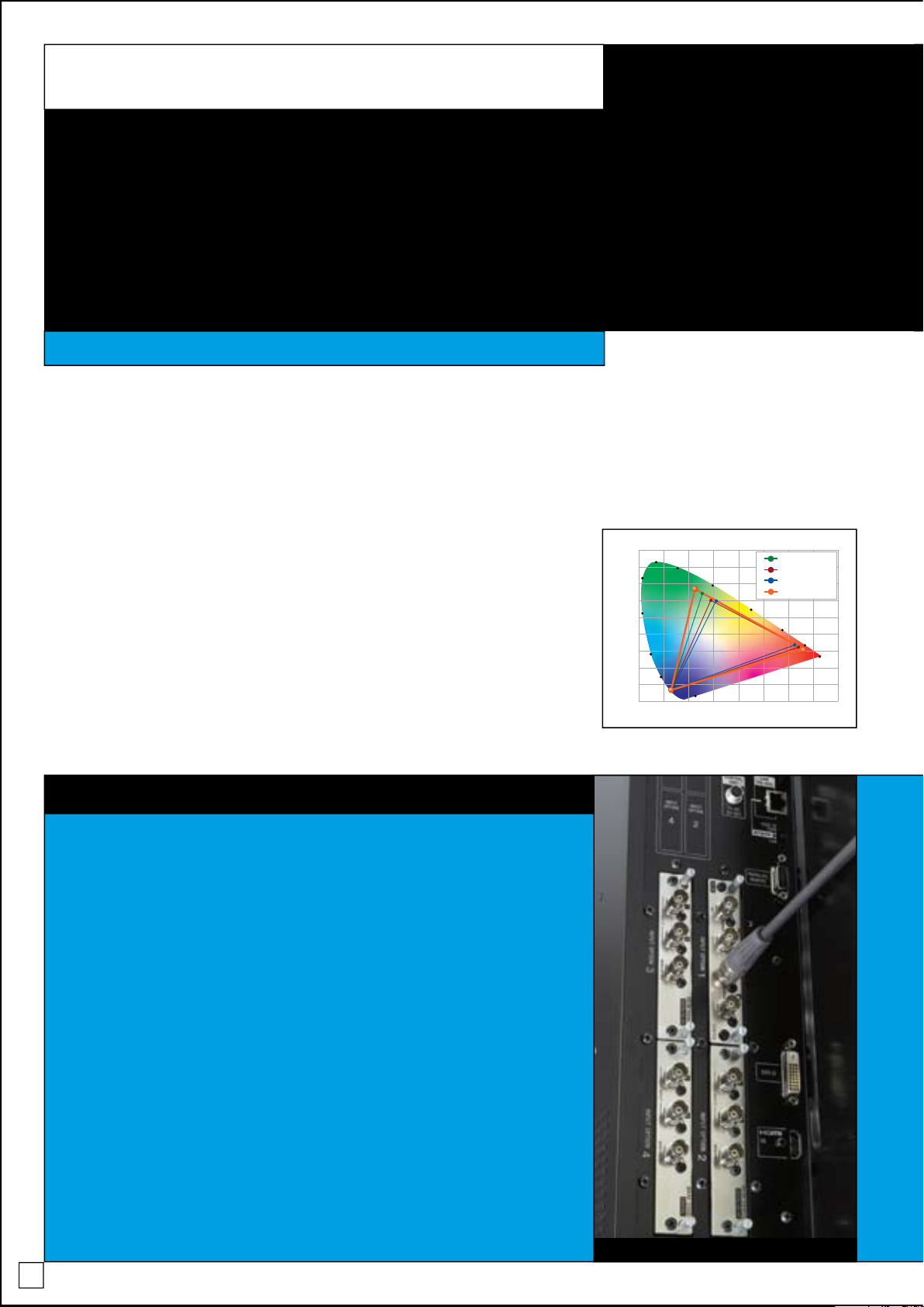
Multiple Colour Gamuts
(SMPTE-C, EBU, ITU-R BT.709)
2
The PVM-L2300 incorporates the same
colour conversion system as the
BVM-L231 master monitor – the nonlinear
cubic conversion colour management
system – which uses a unique 3-D LUT
(look-up table) to reproduce precise
colour gamuts throughout the entire
grayscale. Also, while wide CCFL
backlights can in general reproduce
wider colour gamuts than conventional
CCFL backlights,
not all wide CCFLs are compatible
with broadcast colour gamuts. The
WCG-CCFL backlight of the PVM-L2300
is designed to emulate BVM-CRT colour
gamuts. And combined with its unique
0.900
0.800
0.700
0.600
0.500
0.400
0.300
0.200
0.100
0.000
0.100 0.200 0.300 0.400 0.500 0.600 0.700 0.800
520
510
500
490
480
470
530
550
570
590
610
700~
780
380~410
SMPTE-C
EBU
L230 NATIVE
D-Cine
colour management system, this
enables the PVM-L2300 to accurately
reproduce colour gamuts that emulate
2
broadcast standards such as ITU-R
BT.709, and EBU and SMPTE-C phosphor
standards. Compared to past CRT
monitors, which offer only one colour
gamut per model, the PVM-L2300 allows
these colour gamuts to be selected and
reproduced on the same monitor – a
feature only made possible by Sony’s
unique monitor technologies.
2 The PVM-L2300 conforms to these colour standards.
Main features
Input Versatility
The PVM-L2300 can accept almost any SD or HD video format, both analog and
digital, plus PC signals from VGA to WUXGA (1920 x 1200). In addition to a DVI-D
and an HDMI interface equipped as standard, four option board slots are offered
to confi gure the PVM-L2300 according to different user needs. The optional analog
interfaces accept composite, Y/C, Y/PB/PR, and RGB. Digital interfaces accept SDSDI, HD-SDI, Dual-Link HD-SDI, and 3G SDI inputs. Acceptable signal formats include:
525/60i, 625/50i, 525/60P, 625/50P, 720/50P and 720/60P, 10-bit/
12-bit RGB 4:4:4 1080/24PsF, 1080/24P, 1080/25PsF, 1080/25P, 1080/50i, 1080/30PsF,
1080/30P and 1080/60i, 10-bit 4:2:2 1080/50P and 1080/60P.
3G SDI Interface (V1.1 Feature)
The PVM-L2300 can be equipped with an optional 3G SDI interface. The
BKM-250TG 3G SDI interface board is compliant with the SMPTE 425 standard
and requires only one single SDI cable to transmit up to 10-bit 4:2:2 1080/60P video
signals. This optional 3G SDI interface offers a simple cabling solution for groups of
video equipment rack-mounted behind a sub-control room.
PVM-L2300 with BKM-250TG 3G SDI board
Superb Picture Quality and Stable Colour Reproduction
Multi-format Signal Support up to 3G SDI
4
Page 5
depth using the Wide Colour Gamut
CCFL backlight system.
Professional Display Engine
The PVM-L2300 incorporates the display
engine used in the BVM-L231 master
monitor. This unique nonlinear cubic
conversion colour management
system, plus exclusively developed
I/P conversion technology, enables
the PVM-L2300 to reproduce images
faithfully.
Consistent Picture Quality
Each and every PVM-L2300 monitor
is carefully calibrated at the factory
on an individual basis, providing a
high level of accuracy and stability for
characteristics such as gamma and
uniformity. Also, a feedback system
supports this stability by constantly
detecting both the luminance level
and white balance.
PVM-L2300 Acceptable Signal Formats
NO
System
Nomenclature
Samples
per active
line
Active lines
per frame
Frame Rate
fV (Hz)
Interface
sampling freq
(MHz)
Samples
per active
line
Total lines
per frame
Line
Frequency
fH (kHz)
Standard
1 525/59.94i 720 487 59.94 13. 5 858 525 15.73 Rec.ITU- R BT.601
2 625/50i 720 576 50 13. 5 864 625 15. 63 Rec.ITU-R BT.601
3 525/59.94P 720 483 59.94 27 858 525 31.47
SMPTE 293M/Rec.ITU-R BT.1358
4 625/50P 720 576 50 27 864 625 31. 25 Rec.ITU-R BT.1358
5 1920 x 1080/24PsF
3
192 0 1080 48/47.95
74.25
74.25/1.001
2750
2750
112 5 2 7.0 0 SMPTE RP 211
6 1920 x 1080/24P
3
192 0 1080 24/23.97
74.25
74.25/1.001
2750 112 5 2 7.0 0 SMPTE 274M
7 1920 x 1080/25PsF 192 0 1080 50 112 5 28 .13 R P 2 11
8 1920 x 1080/25P 192 0 1080 25 74.25 2640 112 5 2 8.13 SMPTE 274M
9 1920 x 1080/50i 1920 1080 50 74.25 2640 112 5 28 .13 SMPTE 274M
10 1920 x 1080/30PsF
3
192 0 1080 60/59.94 112 5 3 3.75 R P 2 11
11 1920 x 1080/30P
3
192 0 1080 30/29.97
74.25
74.25/1.001
2200 112 5 33.75 SMPTE 274M
12 1920 x 1080/60 i
3
192 0 1080 6/59.94
74.25
74.250/1.001
2200
2200
112 5 3 3.75 SMPTE 274M
13 1280 x 720/24P
3
128 0 720 24/23.97
74.25
74.25/1.001
4125 750 18. 00 SMPTE 296M
14 1280 x 720/25 P 128 0 720 25 74.25 3960 750 18 .75 SMPTE 296M
15 1280 x 720/30 P
3
128 0 720 30/29.97
74.25
74.25/1.001
3300 75 0 22.5 0 SMPTE 296M
16 1280 x 720/50P 12 80 720 50 74.25 198 0 750 3 7.5 0 SMPTE 296M
17 1280 x 720/60P
3
128 0 720 60/59.94
74.25
74.250/1.001
165 0
165 0
750 45.0 0 SMPTE 296M
18 1920 x 1080/50 P 192 0 1080 50 14 8.5 2640 11 25 56.25 SMPTE 274M
19 1920 x 1080/60P
3
192 0 1080 60/59.94
148 .5
148.5/1.001
2200 112 5 67. 50 SMPTE 274M
3 Also compati ble with 1/1.001 fram e rates.
Digital Uniformity Correction
Typically, LCD monitors exhibit poor
uniformity performance. With the
PVM-L2300, white can be reproduced
uniformly right across the screen. At the
factory, grayscale levels are precisely
measured at each area of the panel
and if differences are detected
between areas, they are accurately
corrected by electrical means.
1920 x 1200 Panel With
10-bit LCD Driver
The PVM-L2300 incorporates the latest
10-bit LCD driver and can achieve both
high resolution and stunning colour
5
Page 6
Main features
Multi-format Signal Support up to 3G SDI
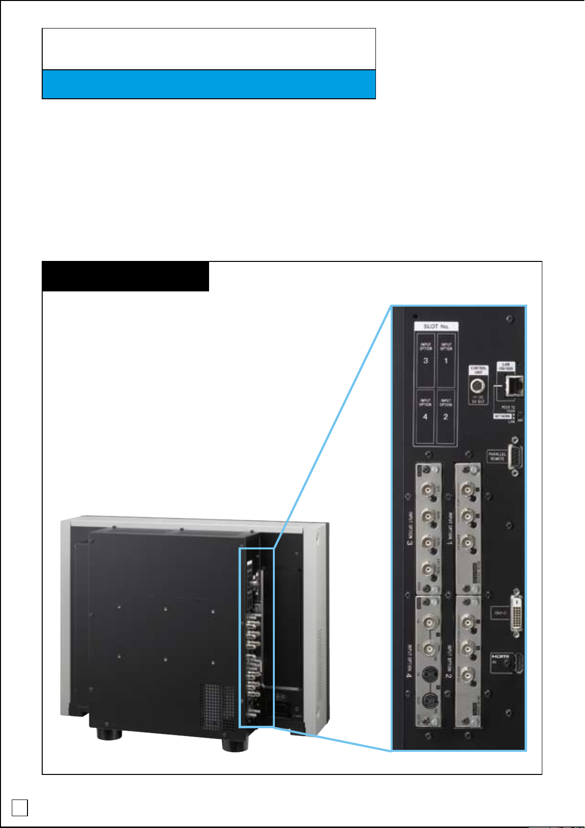
Flexible Input Configuration
Like both the BVM CRT and LCD master monitor series, the PVM-L2300 uses a modular
slot design so inputs can be configured according to individual needs. Four input
board slots are available. Optional input boards
and in almost any combination, allowing easier configuration and better cost-perinput value. These option boards utilize only one slot each, so up
to four cards can be installed for maximum flexibility.
1 The PVM-L2300 input boards are compatible with the BVM-L Series LCD master monitors.
Input Board Slots
1
can be installed in any board slot,
6
Page 7

Interface Chart by Input Boards
Board
Input Signal
System Nomenclature S ignal Format
525/59.94i
625/50i
Compos ite, Y/C
(NT SC/PAL/ PAL-M /SEC AM)
Compos ite, Y/C
(NT SC/PAL/ PAL-M /SEC AM)
525/59.94i Y/PB/PR, GBR
B/PR
, GBR
B/PR
Y/P
, GBR
Y/PB/PR, GBR
B/PR
, GBR
B/PR
, GBR
Analog Input
625/50i Y/P
1080/24Psf
1080/24P
2
2
1080/50i (25PsF) Y/ P
1080/25P Y/P
625/50P Y/PB/PR, GBR
SD-SDI
HD-SDI
525/59.94P Y/PB/PR, GBR
1080/60i (30PsF)
1080/30P
720/50P Y/PB/PR, GBR
720/60P
525/59.94i Y/PB/P
625/50i Y/PB/P
1080/24PsF
1080/25PsF 10bit 4:2:2 Y/PB/P
1080/30PsF
1080/50i 10bit 4:2:2 Y/PB/P
1080/60i
1280 x 720/60P
1280 x 720/50P 10bit 4:2:2 Y/PB/P
1080/24PsF
1080/24P
2
2
2
2
2
2
2
2
2
B/PR
Y/P
, GBR
B/PR
Y/P
, GBR
Y/PB/PR, GBR
R
R
10bit 4:2:2 Y/PB/P
10bit 4:2:2 Y/PB/P
10bit 4:2:2 Y/PB/P
10bit 4:2:2 Y/PB/P
10bit 4:4:4 Y/PB/PR, GBR
12bit 4:4:4 GBR
10bit 4:4:4 Y/PB/PR, GBR
12bit 4:4:4 GBR
R
R
R
R
R
R
R
1080/25PsF 10bit 4:4:4 Y/PB/PR, GBR
1080/25P 12bit 4:4:4 GBR
2, 4
4
2, 4
4
2, 4
10bit 4:4:4 Y/PB/PR, GBR
12bit 4:4:4 GBR
12bit 4:4:4 GBR
10bit 4:4:4 Y/PB/PR, GBR
12bit 4:4:4 GBR
10bit 4:4:4 Y/PB/PR, GBR
12bit 4:4:4 GBR
10bit 4:2:2 Y/PB/P
10bit 4:4:4 Y/PB/PR, GBR
12bit 4:4:4 Y/PB/PR, GBR
10bit 4:4:4 Y/PB/PR, GBR
12bit 4:4:4 Y/PB/PR, GBR
10bit 4:4:4 Y/PB/PR, GBR
12bit 4:4:4 Y/PB/PR, GBR
10bit 4:4:4 Y/PB/PR, GBR
12bit 4:4:4 Y/PB/PR, GBR
10bit 4:4:4 Y/PB/PR, GBR
12bit 4:4:4 Y/PB/PR, GBR
10bit 4:4:4 Y/PB/PR, GBR
12bit 4:4:4 Y/PB/PR, GBR
10bit 4:4:4 Y/PB/PR, GBR
12bit 4:4:4 Y/PB/PR, GBR
10bit 4:4:4 Y/PB/PR, GBR
12bit 4:4:4 Y/PB/PR, GBR
10bit 4:2:2 Y/PB/P
R
R
R
R
10bit 4:4:4 Y/PB/PR, GBR
10bit 4:4:4 Y/PB/PR, GBR
10bit 4:4:4 Y/PB/PR, GBR
10bit 4:4:4 Y/PB/PR, GBR
10bit 4:4:4 Y/PB/PR, GBR
Dual- Link HD -SDI
3G SDI
1080/30PsF
1080/30P
2
2
1080/50i
2
1080/60i
1080/50P 10bit 4:2:2 Y/PB/P
2
1080/60P
1080/24PsF
1080/25PsF
1080/30PsF
1080/24P
1080/25P
1080/30P
1080/50i
1080/60i
1080/50P 10bit 4:2:2 Y/PB/P
1080/60P
2, 4
4
2, 4
2, 4
4
2, 4
4
4
2
1280 x 720/24P
1280 x 720/25P
1280 x 720/30P
1280 x 720/50P
1280 x 720/60P
Number of digi tal inputs
Number of analog input s
1 Two BKM-243HS or BKM-244CC, or one BKM-250TG optional boards are used.
2 Also compatible with 1/1.001 frame rates.
3 BKM-243HS, BKM-244CC and BKM-250TG automatically detect SD-SDI and HD-SDI input signals.
4 Untested
BKM-220D BKM-227W BKM-229X BKM-243HS3BKM-244CC3BKM-250TG
●
●
●
●
●
●
●
●
●
●
●
●
●
●
● ● ● ●
● ● ● ●
● ● ●
● ● ●
● ● ●
● ● ●
● ● ●
● ● ●
● ● ●
1 •
●
1 •
●
1 •
●
1 •
●
1 •
●
1 •
●
1 •
●
1 •
●
1 •
●
1 •
●
2
_
_ _
1 1
2 2 2
_ _ _
1 •
●
1 •
●
1 •
●
1 •
●
1 •
●
1 •
●
1 •
●
1 •
●
1 •
●
1 •
●
3
1 •
●
1 •
●
1 •
●
1 •
●
1 •
●
1 •
●
1 •
●
1 •
●
1 •
●
1 •
●
●
●
●
●
●
●
●
●
●
●
●
●
●
●
●
7
Page 8

BKM-250TG, 3G/HD/SD-SDI Input Adaptor
1
> 3G/HD/SD-SDI signal input (x2)
> 3G/HD/SD-SDI monitor output (x2)
> Power consumption: Approx. 4 W
1 3G-SDI, HD-SDI and SD-SDI signals are detected automatically
BKM-243HS, HD-SDI/SD-SDI Input Adaptor
2
> HD-SDI/SD-SDI signal input (x2)
> HD-SDI/SD-SDI monitor output (x1)
> Power consumption: 2.0 W
2 HD-SDI and SD-SDI signals are detected automatically
BKM-227W, NTSC/PAL Input Adaptor
> Composite input/output (x1)
> Y/C input/output (x1)
> Power consumption: 1.8 W
BKM-244CC, HD/SD-SDI Closed Caption Adaptor
3
> HD-SDI/SD-SDI signal input (x2)
> HD-SDI/SD-SDI monitor output (x1)
> Power consumption: 3.8 W
3 HD-SDI and SD-SDI signals are detected automatically,
Closed-caption decoders (EIA 608 and EIA 708) are equipped
BKM-229X, Analog Component Adaptor
> RGB,Y/PB/PR input (x1)
> EXT SYNC (x1)
> Power consumption: 4.0 W
BKM-220D, SD-SDI 4:2:2 Input Adaptor
> SD-SDI signal input (x2)
> SD-SDI monitor output (x1)
> Power consumption: 1.5 W
3G-SDI/HD-SDI/SD-SDI
signal input (x2)
HD-SDI/SD-SDI signal
input (x2)
RGB/ Y/PB/PR input (x1)
SD-SDI signal input (x2)
HD-SDI/SD-SDI signal
input (x2)
Composite input/
output (x1)
3G-SDI/HD-SDI/SD-SDI
signal output (x2)
HD-SDI/SD-SDI monitor
output (x1)
EXT SYNC (x1)
SD-SDI monitor
output (x1)
HD-SDI/SD-SDI monitor
output (x1)
Y/C input/output (x1)
Signal-interface Options
Main features
8
Page 9

The PVM-L2300 monitor and the
BKM-16R controller attached with
the BKM-38H attachment stand.
The monitor and control panel are provided as separate units, allowing greater
fl exibility for system integration. Like the BVM-L231 master monitor, the PVM-L2300
incorporates the BKM-16R Monitor Control Unit, which can be attached below
the monitor using an optional Controller Attachment Stand (either the BKM-37H or
BKM-38H), or connected remotely via an Ethernet cable.
The PVM-L2300 monitor and BKM-16R Monitor Control Unit are equipped with
an Ethernet port, allowing remote control of monitor settings across a standard
Ethernet connection. One BKM-16R Monitor Control Unit can control up to thirty-two
(32) monitors
4
.
4 BVM-A CRT monitors and both BVM-L and PVM-L LCD monitors.
Front Panel
BKM-16R Monitor Control Unit
Rear Panel
Operational convenience
The PVM-L2300 is equipped with the same acclaimed
functions and operational conveniences of the BVM CRT and
BVM LCD master monitors. It also has some additional unique
features, which are only made possible by Sony’s fl at-panel
technology.
Modular Monitor Control Unit (BKM-16R)
Ethernet-based Remote Control
9
Page 10

Operational convenience
Copy function
The optional BKM-16R control unit has a Memory Stick® slot1 to save and load
monitor setup and adjustment data. This is useful for multiple monitor systems,
allowing the same setup and adjustment data to be loaded onto each unit
This data can also be transferred via the BVM’s Ethernet connection.
1 Both standard-size Memor y Stick media and the smaller Memory Stick Duo®/Memory Stick PRO Duo® media can be used. A
Memory Stick Duo adaptor is not required.
2 Data can be moved between the BVM-A monitors, BVM-L monitors, and PVM-L monitors, respectively.
Picture & Picture (Side by Side)
The Picture & Picture function allows simultaneous display of two input signals
on the PVM-L2300’s LCD screen. The two picture images are downscaled and
displayed side by side. This function comes in handy for adjustments between
two cameras, special-effects creation, time-lapse shooting, and computergenerated graphics work, since there is no need to individually adjust the different
characteristics of two monitors. This feature offers greater convenience when
making white balance adjustments and/or determining shooting angles between
two cameras.
2
.
Pixel Zoom
The Pixel Zoom function of the
PVM-L2300 is a function for magnifying
images. A selected area of the displayed
picture can be enlarged on a pixel
basis, up to eight times both vertically
and horizontally. Because the function
does not use scaling, the desired picture
content is magnified and displayed
faithfully to the raw input signal. This
function is useful when evaluating precise
picture edges, such as for chroma keying.
3 This function is effective when the input signal is displayed by
the “Native Scan” mode.
Error Signal
10
Page 11

Aspect Correction Mode
A major difference between CRT and LCD monitors is the shape of their respective pixel arrays. CRT monitors use a
non-square array, while LCD displays adopt a square-shaped array. Aspect Correction Mode is a technique used by LCD
displays to overcome this difference and emulate the look of a CRT image. Using a scaling technique, this function arranges
the SD input signal to emulate the CRT’s non-square pixel array in a horizontal direction. It also applies the appropriate
scaling algorithm depending on the video format, NTSC or PAL. An interlace display mode can also be applied when
necessary, enabling the monitor to reproduce familiar-looking SD images.
Normal Scan Native Scan (x2) Aspect Correction
2
x
SD 4:3
SD 16:9
(Squeeze)
487
2
x
487
Example of NTSC signal on the 16:10
aspect panel - PVM-L2300
Native Scan (pixel-to-pixel display)
Conventional flat panel monitors reproduce images using scaling and I/P conversion due to their fixed pixel counts and
progressive scanning processes. The Native Scan function equipped on the PVM-L2300 is a unique display mode that reproduces
images without changing the input signal’s pixel count. For example, when an SD signal is input, the PVM-L2300 will reproduce the
image at a picture size of 720 x 487
to be doubled to 1440 x 974
4 525/59.94i signal specified by Rec. ITU-R BT.601
1920 x 1080 Native Scan 720 x 487 Native Scan 1440 x 974 Native Scan (720 x 487) x 2
4
pixels. For SD input in particular, the Native Scan function also allows the image’s display size
4
by duplicating and doubling each pixel both horizontally and vertically.
Scan Switch
The Scan Switch of the PVM-L2300 allows switching between 5%
blanking (or 95% area display), and 0% and -3% Under Scan
mode.
The PVM-L2300 with
the optional BKM-23M Protection Panel
11
Page 12

Operational convenience
Variety of Display Modes
Most flat-panel monitors can only display progressive images at the input signal’s
frame rate. However, the PVM-L2300 has two additional and unique display modes
– Black Frame Insertion Display and Interlace Display:
Black Frame Insertion Display
Combining its high frame-rate operation with a unique Black Frame Insertion technology,
the PVM-L2300 dramatically reduces motion blur, an artifact that is inherent to LCD
devices. Black Frame Insertion technology generates a “black” frame and inserts this in
every other picture frame. As a result, all of the panel’s LCD molecules are reset to their
default alignments, before the next picture frame is displayed.
This effectively eliminates the image lag caused by inconsistencies in the speed at which
LCD molecules are realigned in accordance with the video signal change. Because the
number of frames is doubled, Black Frame Insertion Display reproduces the combined
picture content at twice the speed of the input signal’s frame rate
1 Supports 120-Hz and 100-Hz frame rates.
100/120Hz Black Frame Insertion Display
1
.
Interlace Display
The Interlace Display mode of the
PVM-L2300 can display interlace input
signals as interlace fields. As with the
Native Scan function, the Interlace
Display mode offers faithful reproduction
of the input signal and the displayed
interlace fields are free from the picture
degradation that can occur as a result
of the monitor’s I/P conversion process.
100/120Hz Interlace Display
12
“HD Frame capture”
The HD Frame Capture function of the PVM-L2300
allows a picture frame from the HD-SDI input to be
captured and saved as a picture file on Memory Stick
2
media
. This picture file can be used as a reference for
various purposes, such as for picture-tone adjustments
between past images and for camera-framing
adjustments.
2 Both standard-size Memory Stick media and smaller Memory Stick Duo/Memory
Stick PRO Duo media can be used. A Memory Stick Duo adaptor is not required.
Page 13

Black Detail Mode
Due to the mechanism of an LCD panel, backlight leakage from the panel surface
is unavoidable. Black Detail Mode is a function that provides more accurate
monitoring of black details in dark, low-APL images. With the PVM-L2300, utilizing a
sophisticated backlight system and a unique signal-processing algorithm, the black
region of the video level is effectively enhanced
an auxiliary function.
1 Video levels higher than 75% are clipped for display. This function can indicate the clipped areas with the zebra pattern.
1
. This function is recommended as
“+12dB Chroma Up” Function
A “Chroma UP” button located on the
front panel of the BKM-16R allows the
Chroma Level to be boosted by +12
dB. This is a convenient feature for
adjusting camera white balance with
a higher degree of accuracy.
60%
down
Factory Preset
-
Backlight Luminance -60%
-
Black Detail Mode
-
cd/m2
1.00
Normal Mode Black Detail Mode
cd/m2
120
100
Brightness
Contrast
80
60
40
Black Det ail
Mode
20
75%
Video Level
100 % 109 %0
Zebra
Pattern
13
Page 14

Screen Size: 16:9
Aspect Mode: 4:3
Aspect Marker Colour: Magenta
Marker Bright: 90IRE
Width: THICK
Safe Area: Shape A
Area Size: 80%
Centre Marker: Short
Aspect Blanking: Off
Screen Size: 16:9,
Aspect Mode: 4:3,
Aspect Marker Colour: Green,
Marker Bright: 90IRE,
Width: THICK,
Safe Area: SHAPE C,
Area Size: 80%,
Centre Marker: LONG,
Aspect Blanking: BLACK
Screen Size: 16:9,
Aspect Mode: 4:3,
Aspect Marker Colour: Yellow,
Marker Bright: 40IRE,
Width: THIN,
Safe Area: Shape B,
Area Size: 80%,
Centre Marker: Short,
Aspect Blanking: HALF
Safe Area Marker
Aspect Marker
% Dot (Pixel)
Selectable
Markers
80%, 88%, 90%, 93%,
or vari-
able
Flexible
16:9, 4:3
Line Colours
White, Red, Green, Blue, Yellow, Cyan, or Magenta
Line Width
Thick or Thin
Line Luminance
90 IRE or 40 IRE
Marker Variation
Marker Settings
Operational convenience
Like the earlier BVM Series CRT monitors
and BVM-L Series LCD monitors, the
PVM-L2300 monitor can display
various markers, including an aspect
marker, safe area marker, and centre
marker. In addition to this fl exible
selection of marker types, detailed
display settings of each marker are
offered. For example, the colour,
brightness, horizontal/vertical position,
and width of aspect markers can all
be controlled, while the height and
width of safe area markers can be
adjusted. What’s more, users can
also choose to display two safe area
markers, each selectable between
three marker variations. These fl exible
marker controls, together with the
choice of many different marker types
such as aspect marker types (lines or
aspect blanking) and centre marker
types (long or short), make the
PVM-L2300 monitor the perfect allround display device for a variety of
shooting scenarios.
Marker Examples
14
Page 15

Other Features
Auto white balance
The colour temperature and white
balance of the PVM-L2300 monitor
can be automatically adjusted by the
Auto White Balance function using the
specifi ed colour temperature probes
1
,
such as the Konica Minolta CA-210,
DK-Technologies PM5639/06, and X-Rite
i1 (Eye-One) Pro.
1 A connector is required for each colour analyzer.
Auto Chroma/Phase
Adjustment
2
An Auto Chroma/Phase/Matrix setup
function is provided on the PVM-L2300,
which automatically adjusts the monitor’s
chroma, phase, and matrix using external
colour bars.
2 Supports analog signal input only.
Internal Test Signal and
SMPTE Colour
The PVM-L2300 incorporates a builtin test signal generator for: 100%
white signal, 20% gray signal, 0%
black signal, PLUGE (Picture Line Up
Generating Equipment) signal, colourbar signals, 5-step grayscale signal, and
ramp signal.
“Character Off” Button
(BKM-16R)
To facilitate manual adjustments, the
On-Screen Menu indication can be
taken off the screen, while the Menu
mode is still active. The On-Screen
Menu indication can be toggled on or
off simply by the press of a button on
the BKM-16R’s front panel.
Colour Temperature
Selection
The Colour Temperature can be
selected from D65, D93, or User1
to User5. A “Colour Temp” (Colour
Temperature) button located on the
BKM-16R’s front panel enables instant
access to the “Colour Temp menu”
without using the On-Screen menu.
Aspect Switch
The aspect ratio of the PVM-L2300 can
be switched between 4:3 and 16:9
depending on the input signal.
> VESA
TM
Mounting (200 x 100 mm pitch)
> Blue Only
> Mono
> H Delay/V Delay
> NTSC Setup Level (0%, 7.5%)
> Component Level (SMPTE/EBU-N10 or
Betacam)
> Aperture
> Serial Remote (Ethernet)
> Parallel Remote (D-sub 9-pin)
> Tally Lamp (Amber)
> EXT Sync (for RGB/YUV)
> Remote Maintenance
PVM-L2300 with the BKM-38H Controller Attachment Stand
Easy setup and adjustment
15
Page 16

Specifications
PVM-L2300
PICTURE PERFORMANCE
Type
Picture Size
(Viewable Area)
Aspect
Resolution (H x V)
Pixel Efficiency
Backlight
Preset Brightness
Panel drive
Panel frame rate
Viewing angle
INPUT/OUTPUT
Video Input/Output
PC input
Control
DC 5V Out
GENERAL
Power Requirements
Power consumption
Operating Temperature
Operating Humidity
Operating Pressure
Storage and Trans. Temperature
Storage and Trans. Humidity
Storage and Trans. Pressure
Dimensions (W x H x D)
Mass
Supplied Accessories
(H x V)
(Diagonal)
LAN
Parallel Remote
Option A
Option B
a-Si TFT Active Matrix LCD
Approx. 484 x 303 mm (Approx. 19 1/8 x 12 inches)
571 mm (22 1/2 inches)
16 :10
1920 x 1200 pixels (WUXGA)
99.99 %
Wide CCFL
100 cd/m2 (when 100 % white signal is input)
RGB 10 bit
96/100/120 Hz
85°/85°/85°/85° (up/down/left/right contrast > 10:1)
Four (4) slots
DVI-D (HDCP correspondence) x 1,
HDMI x 1 HDCP correspondence, Deep colour correspondence
Ethernet (10 BASE-T/100 BASE-TX), RJ-45 x 1
D-sub 9-pin (female) x 1
Mini-DIN 8-pin (female) x 1
USB (Type A) x 1 (used for future expansion)
Circle 4-pin (female) x 1
100 to 240 V AC, 50/60 Hz
Approx. 140 W (at maximum load)
Approx. 80 W (with 1 x BKM-243HS)
0 °C to 35 °C (32 °F to 95 °F) (Recommended operation temperature 20 °C to 30 °C (68 °F to 86 °F))
0 % to 90 % (no condensation)
700 hPa to 1060 hPa
-20 °C to +60 °C (-4 °F to +140 °F)
0 % to 90 %
700 hPa to 1060 hPa
565.5 x 435.2 x 243.1 mm (22 3/8 x 19 x 9 5/8 inches)
Approx. 16 kg (Approx. 35 lb 4 oz)
AC power cord (1), AC plug holder (1), Bracket (1),
Operation Manual (Japanese, English, each 1),
Connection Cable for Colour Temperature Probe (1), CD-ROM (1), Using the CD-ROM Manual (1)
16
BKM-16R
INPUT/OUTPUT
LAN
DC 5V/12V IN
GENERAL
Power Requirements
Current Consumption
Power Consumption
Operating Temperature
Operating Humidity
Operating Pressure
Storage and Trans. Temperature
Storage and Trans. Humidity
Storage and Trans. Pressure
Dimensions (W x H x D)
Mass
Supplied Accessories
10BASE-T/100BASE-TX connector: RJ-45 x 1
Circle 4-pin (male) x 1
DC IN: 5 V, 1.1 A (supplied by the connected monitor)
DC IN: 12 V, 0.5 A (supplied by the connected AC adaptor)
AC adaptor: AC IN: 100 to 240 V, 50/60 Hz, DC OUT: 12 V, 3 A
5 V DC, 1.1 A/12 V DC, 0.5 A
Approx. 6 W
0 °C to 35 °C (32 °F to 95 °F) (Recommended operating temprature 20 °C to 30 °C (68 °F to 86 °F))
0 % to 90 % (no condensation)
700 hPa to 1060 hPa
-10 °C to + 40 °C (14 °F to 104 °F)
0 % to 90 %
700 hPa to 1060 hPa
424 x 58.8 x 174.9 mm (16 3/4 x 2 3/8 x 7 inches)
Approx. 2.1 kg (4 lb 10 oz)
AC adaptor (1), AC power cord (parts number: 1-757-562-1x1 for USA and Canada,
1-575-131-8x for Europe) (1), Rack mount brackets (2), Rack mount attachment screws (4),
Function labels (2), Operation manual (1)
Page 17

Specifications
BKM-250TG
INPUT/OUTPUT
BNC x 2,
Serial Digital Interface
Monitor Out
Transmission Distance
Digita l component s ignals S ampling f requency
3G-SD I: Y/Cb/Cr: 148.5 MHz/74.25 MHz/74.25 MHz,
G/B/R: 148.5 MHz/148.5 MHz/148.5 MHz
HD-S DI: Y/Cb/Cr: 74.25 MHz/37.125 MHz/37.125 MHz,
SD-S DI: Y/Cb/Cr: 13.5 MHz/6.75 MHz/6.75 MHz
BNC x 1, Output s ignal amp litude: 80 0 mVp-p ± 10 %
Output i mpedanc e: 75 Ω unbalanced
3G-SD I: 50 m (approx. 164 ft) max . (When us ing 5C-FB
coaxia l cables (Fuji kura. Inc.) or equ ivalent.)
HD-S DI: 100 m (approx. 328 ft) ma x. (When u sing 5C-FB
coaxia l cables (Fuji kura. Inc.) or equ ivalent.)
SD-S DI:200 m (approx . 656 ft) max. (W hen usin g 5C-2V
coaxia l cables (Fuji kura. Inc.) or equ ivalent.)
GENERAL
Volta ge +5 V, +3.3 V (supp lied from the m ain unit)
Power Consumption Approx. 4 W
Operating Temperature
Operating Humidity 0 % to 90 % (no conde nsation)
Operating Pressure 700 hPa to 1060 hPa
Storage and Trans. Temperature -20 °C to +60 ° C (14 °F to 104 °F)
Storage and Trans. Humidity 0 % to 90 %
Storage and Trans. Pressure 700 hPa to 1060 hPa
Dimen sions (W x H x D) 100 x 20 x 162 mm (4 x 13/16 x 6 1/2 inches)
Mass Approx. 270 g (9.5 oz)
Supplied Accessories O perating I nstructi ons (1)
(Optimum t emperatu re 20 °C to 30 °C (68 °F to 86 °F))
0 °C to 35 °C (32 °F to 95 °F)
BKM-243HS
INPUT/OUTPUT
BNC x 2, Dig ital Compon ent Signa ls
Serial Digital Interface
Monitor Out
Transmission Distance
Sampli ng Frequenc y: SD-SD I: Y/R-Y/B-Y: 13.5 MHz,
HD-S DI: Y/Pb/Pr: 74.25 MHz
Quanti zation: 10 bits/sa mple
Output s ignal am plitude: 80 0 mVp-p ± 10 %
Output i mpedanc e: 75 Ω unbalanced
SD-S DI: 200 m (appro x. 656 ft) max. (wh en using
5C-2V coaxia l calbes (Fuj ikura) or equ ivalent)
HD-S DI: 100 m (approx. 328 ft) ma x. (when usi ng
5C-FB coax ial cable s (Fujikura) or eq uivalent)
BNC x 1,
GENERAL
Volta ge +3.3 V (supplied fro m the main un it)
Power Consumption Approx. 2 W
Operating Temperature
Operating Humidity 0 % to 90 % (no conde nsation)
Operating Pressure 700 hPa to 1060 hPa
Storage and Trans. Temperature
Storage and Trans. Humidity 0 % to 90 %
Storage and Trans. Pressure 700 hPa to 1060 hPa
Dimen sions (W x H x D) 100 x 20 x 162 mm (4 x 13/16 x 6 1/2 inches)
Mass Approx. 250 g (9 oz)
Supplied Accessories O perating I nstructi ons (1)
0 °C to 35 °C (32 °F to 95 °F) (Re commende d
operati on temperat ure 20 °C to 30 °C (68 °F to 86 ° F))
-
10 °C to 40 °C (14 °F to 104 °F)
BKM-227W
INPUT/OUTPUT
Composite Input
Y/C I nput
Monitor Out
C: 0.286 Vp-p ± 3 dB (NT SC burst si gnal level),
0.3 Vp-p ± 3 dB (PAL b urst sign al level) (SECA M, PAL-M)
BNC x 1, Loop-thro ugh, with 75 Ω automat ic termina tion
Loop-th rough, with 75 Ω automat ic termina tion
BNC x 1,
1 Vp-p ± 3 dB sy nc negati ve
4-pin mi ni DIN x 1
Y: 1 Vp-p ± 3 dB syn c negative
4-pin mi ni DIN x 1,
GENERAL
Volta ge +3.3 V (supplied fro m the main un it)
Power Consumption Approx. 1.8 W
Operating Temperature
Operating Humidity 0 % to 90 % (no conde nsation)
Operating Pressure 700 hPa to 1060 hPa
Storage and Trans. Temperature
Storage and Trans. Humidity 0 % to 90 %
Storage and Trans. Pressure 700 hPa to 1060 hPa
Dimen sions (W x H x D) 100 x 20 x 162 mm (4 x 13/16 x 6 1/2 inches)
Mass Approx. 240 g (8 oz)
Supplied Accessories O perating I nstructi ons (1)
0 °C to 35 °C (32 °F to 95 °F) (Re commende d
operati on temperat ure 20 °C to 30 °C (68 °F to 86 ° F))
-
10 °C to 40 °C (14 °F to 104 °F)
BKM-244CC
INPUT/OUTPUT
BNC x 2,
Serial Digital Interface
Monitor Out
Transmission Distance
Digita l Componen t Signals
Sampli ng Frequenc y: SD-SD I: Y/R-Y/B-Y: 13.5 MHz,
HD-S DI: Y/Pb/Pr: 74.25 MHz
Quanti zation: 10 bits/sa mple
Output s ignal am plitude: 80 0 mVp-p ± 10 %
Output i mpedanc e: 75 Ω unbalanced
SD-S DI: 200 m (appro x. 656 ft) max. (wh en using
5C-2V coaxia l calbes (Fuj ikura) or equ ivalent)
HD-S DI: 100 m (approx. 328 ft) ma x. (when usi ng
5C-FB coax ial cable s (Fujikura) or eq uivalent)
BNC x 1,
GENERAL
Volta ge +5 V, +3.3 V (supp lied from the m ain unit)
Power Consumption Approx. 3.8 W
Operating Temperature
Operating Humidity 0 % to 90 % (no conde nsation)
Operating Pressure 700 hPa to 1060 hPa
Storage and Trans. Temperature
Storage and Trans. Humidity 0 % to 90 %
Storage and Trans. Pressure 700 hPa to 1060 hPa
Dimen sions (W x H x D) 100 x 20 x 162 mm (4 x 13/16 x 6 1/2 inches)
Mass Approx. 250 g (9 oz)
Supplied Accessories O perating I nstructi ons (1)
0 °C to 35 °C (32 °F to 95 °F) (Re commende d
operati on temperat ure 20 °C to 30 °C (68 °F to 86 ° F))
-
10 °C to 40 °C (14 °F to 104 °F)
BKM-229X
INPUT/OUTPUT
RGB Inpu t
Component Input
0.7 Vp-p ± 3 dB
BNC x 1,
4-pin mi ni DIN x 1,
BNC x 3
External Sync Input
0.7 Vp-p ± 3 dB (Sy nc on Green, 0.3 Vp -p sync neg ative)
0.3 to 4 Vp-p ± bip olarit y ternar y or negati ve polarit y binar y
Loop-th rough, with 75 Ω automat ic termina tion
GENERAL
Volta ge +3.3 V, +5 V (supp lied from the m ain unit)
Power Consumption Approx. 4 W
Operating Temperature
Operating Humidity 0 % to 90 % (no conde nsation)
Operating Pressure 700 hPa to 1060 hPa
Storage and Trans. Temperature
Storage and Trans. Humidity 0 % to 90 %
Storage and Trans. Pressure 700 hPa to 1060 hPa
Dimen sions (W x H x D) 100 x 20 x 162 mm (4 x 13/16 x 6 1/2 inches)
Mass Approx. 250 g (9 oz)
Supplied Accessories O perating I nstructi ons (1)
0 °C to 35 °C (32 °F to 95 °F) (Re commende d
operati on temperat ure 20 °C to 30 °C (68 °F to 86 ° F))
-
10 °C to 40 °C (14 °F to 104 °F)
BKM-220D
INPUT/OUTPUT
BNC x 2,
Serial Digital Interface
Monitor Out
Transmission Distance
Digita l Componen t Signals
Sampli ng Frequenc y: Y/R-Y/B-Y: 13.5 MHz
Quanti zation: 10 bits/sa mple
Output s ignal am plitude: 80 0 mVp-p ±10 %
Output i mpedanc e: 75 Ω unbalanced
200 m (approx . 656 ft) max. (wh en using
5C-2V coaxia l calbes (Fuj ikura) or equ ivalent)
BNC x 1,
GENERAL
Volta ge +5 V (supplied f rom the main u nit)
Power Consumption Approx. 1.5 W
Operating Temperature
Operating Humidity 0 % to 90 % (no conde nsation)
Operating Pressure 700 hPa to 1060 hPa
Storage and Trans. Temperature
Storage and Trans. Humidity 0 % to 90 %
Storage and Trans. Pressure 700 hPa to 1060 hPa
Dimen sions (W x H x D) 100 x 20 x 162 mm (4 x 13/16 x 6 1/2 inches)
Mass Approx. 250 g (9 oz)
Supplied Accessories O perating I nstructi ons (1)
0 °C to 35 °C (68 °F to 95 °F) (R ecommend ed
operati on temperat ure 20 °C to 30 °C (68 °F to 86 ° F))
-
10 °C to 40 °C (14 °F to 104 °F)
17
Page 18

Dimensions
PVM-L2300
18
BKM-16R
Page 19

Optional Accessories
BKM-16R
Monitor Control Unit
BKM-220D
SD-SDI 4:2:2 Input Adaptor
BKM-37H
Controller Attachment Stand
1
BKM-250TG
3G/HD/SD-SDI Input Adaptor
BKM-229X
Analogue Component
Adaptor
BKM-38H
Controller Attachment Stand
BKM-244CC
HD/SD-SDI Closed Caption
Adaptor
BKM-227W
NTSC/PAL Input Adaptor
SMF-700
Monitor Interface Cable
BKM-243HS
HD-SDI/SD-SDI Input Adaptor
BKM-23M
Protection Panel
2
1 Tilt function is avail able
2 Can a lso be u sed for the BVM- L231 monitor.
19
Page 20

At Sony Professional
we believe images have
immeasurable power
Images nurture life
connect cultures
grow economies
deliver justice
inspire education
energise entertainment
advance science
liberate imagination
capture history
even promote peace
We use the power of images
to increase business value
We turn images into assets
This is Visual Wealth
Distributed by
PVM-L2300_UK_Brochure_xx/xx/2009
©2009 Sony Corporation. All rights reserved. Reproduction in whole or in part without
permission is prohibited. Features and specifications are subject to change without notice.
All non-metric weights and measurements are approximate. Images on monitors are
simulated.
Sony, TRIMASTER, and Memory Stick are trademarks of Sony Corporation. All other
trademarks are the property of their respective owners.
 Loading...