

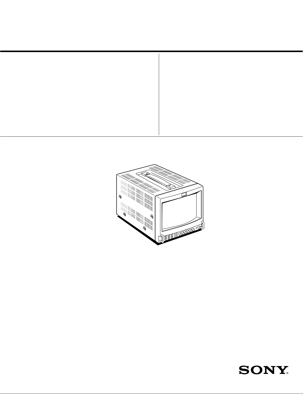
Sony PVM-8042Q, PVM-8045Q, PVM-9042QM, PVM-9045QM, PVM-9045PM Service Manual
SERVICE MANUAL
S MIC
CHASSIS
MODEL
…………… ……… …………………
PVM-8042Q
PVM-8045Q
DEST . CHASSIS NO.
US/CND SCC-E96H-A
US/CND SCC-E96J-A
MODEL
…………… ……… …………………
PVM-9042QM
PVM-9042QM
PVM-9045QM
PVM-9045QM
PVM-9045PM
DEST . CHASSIS NO.
AEP SCC-F09H-A
AUS SCC-F90F-A
AEP SCC-F09J-A
AUS SCC-F90G-A
BRZ SCC-F31B-A
TRINITRON® COLOR VIDEO MONITOR

! WARNING
This manual is intended for qualified service personnel
only .
T o reduce the risk of electric shock, fire or injury , do not
perform any servicing other than that contained in the
operating instructions unless you are qualified to do so.
Refer all servicing to qualified service personnel.
WARNING!!
AN ISOLATION TRANSFORMER SHOULD BE USED DURING ANY
SERVICE TO AVOID POSSIBLE SHOCK HAZARD, BECAUSE OF
LIVE CHASSIS.
THE CHASSIS OF THIS RECEIVER IS DIRECTL Y CONNECTED TO
THE AC POWER LINE.
SAFETY-RELATED COMPONENT WARNING!!
COMPONENTS IDENTIFIED BY MARK
DIAGRAMS, EXPLODED VIEWS AND IN THE PARTS
LIST ARE CRITICAL T O SAFE OPERATION. REPLACE THESE
COMPONENTS WITH SONY PARTS WHOSE PART NUMBERS
APPEAR AS SHOWN IN THIS MANUAL OR IN SUPPLEMENTS
PUBLISHED BY SONY. CIRCUIT ADJUSTMENTS THAT ARE
CRITICAL TO SAFE OPERATION ARE IDENTIFIED IN THIS
MANUAL. FOLLO W THESE PR OCEDURES WHENEVER CRITICAL
COMPONENTS ARE REPLACED OR IMPROPER OPERATION IS
SUSPECTED.
!!
! ON THE SCHEMATIC
!!
ATTENTION!!
AFIN D’EVITER T OUT RISQUE D’ELECTROCUTION PR OVENANT
D’UN CHÁSSIS SOUS TENSION, UN TRANSFORMATEUR
D’ISOLEMENT DOIT ETRE UTILISÉ LORS DE TOUT DÉPANNAGE.
LE CHÁSSIS DE CE RÉCEPTEUR EST DIRECTEMENT
RACCORDÉ À L’ALIMENTATION SECTEUR.
A TTENTION AUX COMPOSANTS RELATIFS À LA
SÉCURITÉ!!
LES COMPOSANTS IDENTIFIÈS PAR UNE TRAME ET PAR UNE
MARPUE
EXPLOSÉES ET LES LISTES DE PIECES CONT D’UNE
IMPORTANCE CRITIQUE PUR LA SÉCURITÉ DU
FONCTIONNEMENT. NE LES REMPLACER QUE PAR DES
COMPOSANTS SONY DONT LE NUMÉRO DE PIÉCE EST INDIQUÉ
DANS LE PRÉSENT MANUEL OU DANS DES SUPPLÉMENTS
PUBLIÉS PAR SONY. LES RÉGLAGES DE CIRCUIT DONT
L’IMPORTANCE EST CRITIQUE POUR LA SÉCURITÉ DU
FONCTIONNEMENT SONT IDENTIFIES DANS LE PRÉSENT
MANUEL. SUIVRE CES PROCÉDURES LORS DE CHAQUE
REMPLACEMENT DE COMPOSANTS CRITIQUES, OU
LORSQU’UN MAUVAIS FONCTIONNEMENT EST SUSPECTÉ.
!!
! SUR LES SCHÉMAS DE PRINCIPE, LES VUES
!!

TABLE OF CONTENTS
1. OPERATING INSTRUCTIONS
2. SERVICE INFORMATION
2-1. CIRCUIT BOARDS LOCATION ................................................................. 2-1
2-2. DISASSEMBLY ............................................................................................2-2
2-2-1. Cabinet Removal .................................................................................... 2-2
2-2-2. B Board Removal ................................................................................... 2-2
2-2-3. Switching Regulator Removal................................................................ 2-3
2-2-4. D Board Removal ................................................................................... 2-3
2-2-5. P Board Removal.................................................................................... 2-4
2-2-6. Rear Assembly Removal ........................................................................ 2-4
2-2-7. HA Board Removal................................................................................. 2-5
2-2-8. CRT Removal ......................................................................................... 2-5
2-2-9. Removal of Anode-cap........................................................................... 2-6
2-2-10. Equipment Required ............................................................................... 2-7
3. SET-UP ADJUSTMENTS
3-1. PREPARATIONS ..........................................................................................3-1
3-2. LANDING ADJUSTMENT........................................................................... 3-2
3-2-1. Preparations ............................................................................................ 3-2
3-2-2. Landing Adjustment ............................................................................... 3-2
3-3. CONVERGENCE ADJUSTMENT ............................................................... 3-3
3-3-1. Horizontal and Vertical Convergence Adjustment on the
Center of Screen ..................................................................................... 3-3
3-3-2. Horizontal and Vertical Dynamic Convergence Adjustment in the
Vicinity of Screen................................................................................... 3-4
3-4. FOCUS ADJUSTMENT ................................................................................ 3-5
3-5. WHITE BALANCE ADJUSTMENT ............................................................ 3-5
3-5-1. Screen Voltage Adjustment .................................................................... 3-5
3-5-2. White Balance Adjustment..................................................................... 3-5
4. SAFETY RELATED ADJUSTMENTS
4-1. B+ VOLTAGE CHECK ................................................................................ 4-1
4-1-1. B+ Voltage Check in AC Operation ...................................................... 4-1
4-1-2. B+ Voltage Check in DC Operation ...................................................... 4-2
4-2. PROTECTION CIRCUIT (HOLD-DOWN CIRCUIT) CHECK .................. 4-2
4-2-1. Shutdown Voltage Adjustment...............................................................4-2
4-2-2. Protection Circuit Operation Check .......................................................4-2
S MIC Chassis
1

5. CIRCUIT ADJUSTMENTS
5-1. D BOARD ADJUSTMENTS.........................................................................5-1
5-1-1. Horizontal Oscillating Frequency Adjustment (RV503)........................5-1
5-1-2. Video Phase Adjustment (RV512, RV516, RV502) ..............................5-1
5-1-3. Vertical Blanking Adjustment (RV501).................................................5-2
5-1-4. Horizontal Blanking Adjustment (RV516) ............................................5-2
5-1-5. Vertical Deflection System Adjustment
(RV505, RV507, RV504, RV518) ......................................................... 5-2
5-1-6. Horizontal Deflection System Adjustment
(RV508, RV509, RV511, RV514, RV515, and RV801/P Board) ......... 5-3
5-1-7. Under Scan Adjustment (RV517, RV512) ............................................. 5-3
5-1-8. Horizontal/Vertical Delay Adjustment (RV832, RV831) ......................5-3
5-2. B BOARD ADJUSTMENTS .........................................................................5-4
5-2-1. Primary Color Matrix Adjustment (1) (RV115).....................................5-4
5-2-2. Primary Color Matrix Adjustment (2) (RV116, RV123) .......................5-4
5-2-3. Burst Gate Pulse Width Adjustment (RV109) .......................................5-5
5-2-4. NTSC Subcarrier Frequency Adjustment (RV1400) .............................5-5
5-2-5. PAL Subcarrier Frequency Adjustment (RV1401) ................................5-5
5-2-6. NTSC Comb Filter Adjustment (RV1, T1/CFM101).............................5-5
5-2-7. NTSC 3.58 MHz Color Demodulation (B-Y) Adjustment
(RV114, RV111) ....................................................................................5-6
5-2-8. NTSC 3.58 MHz Color Demodulation (R-Y) Adjustment
(RV104, RV107) ....................................................................................5-6
5-2-9. NTSC 4.43 MHz Color Demodulation Adjustment (RV108, RV112) .. 5-6
5-2-10. PAL Color Demodulation Adjustment
(RV113, RV2/SEP101, RV110, RV105) ............................................... 5-7
5-2-11. Sub-Sharpness Adjustment (RV205) .....................................................5-7
5-2-12. Chroma H Pulse Adjustment (RV101, RV102) ..................................... 5-7
5-3. S BOARD ADJUSTMENTS .........................................................................5-8
5-3-1. SECAM Bell Filter Adjustment (T1101) ............................................... 5-8
5-3-2. SECAM Color Balance Adjustment (L1102, L1103) ............................5-8
5-3-3. SECAM Demodulation Level Adjustment (RV1101, RV1102) ............ 5-8
6. SEMICONDUCTORS
7. EXPLODED VIEWS
7-1. CHASSIS........................................................................................................7-1
7-2. PICTURE TUBE ............................................................................................7-2
8. ELECTRICAL PARTS LIST
2
S MIC Chassis

9. BLOCK DIAGRAMS
QA (1/2)................................................................................................................ 9-1
HA ...................................................................................................................................................... 9-1
X........................................................................................................................... 9-1
B ........................................................................................................................... 9-2
S ........................................................................................................................... 9-4
QA (2/2)................................................................................................................ 9-4
FA ....................................................................................................................................................... 9-4
G........................................................................................................................... 9-4
D........................................................................................................................... 9-5
CA....................................................................................................................................................... 9-6
P ........................................................................................................................... 9-6
PA ....................................................................................................................................................... 9-6
10. DIAGRAMS
10-1.FRAME SCHEMATIC DIAGRAMS .......................................................... 10-2
10-2.SCHEMATIC DIAGRAMS/PRINTED WIRING BOARDS ..................... 10-4
SCHEMATIC DIAGRAMS
G Board .............................................................................................................. 10-4
QA Board............................................................................................................ 10-5
FA Board ............................................................................................................ 10-7
D (1/2) Board ..................................................................................................... 10-9
D (2/2) Board ................................................................................................... 10-10
P Board............................................................................................................. 10-11
B (1/3) Board ................................................................................................... 10-15
B (2/3) Board ................................................................................................... 10-17
B (3/3) Board ................................................................................................... 10-19
S Board............................................................................................................. 10-20
HA Board.......................................................................................................... 10-21
PA Board .......................................................................................................... 10-21
CA Board ..........................................................................................................10-22
X Board ............................................................................................................ 10-22
PRINTED WIRING BOARDS
G Board .............................................................................................................. 10-4
QA Board............................................................................................................ 10-5
D Board .............................................................................................................. 10-6
FA Board ............................................................................................................ 10-7
P Board............................................................................................................. 10-11
B Board ............................................................................................................ 10-12
S Board............................................................................................................. 10-20
HA Board.......................................................................................................... 10-21
PA Board .......................................................................................................... 10-21
CA Board ..........................................................................................................10-22
X Board ............................................................................................................ 10-22
S MIC Chassis
3

S MIC Chassis
3-865-058-11 (1)
1
(EN)
PVM-8045Q PVM-8042Q
PVM-8040
Operating Instructions
Mode d’emploi
Manual de instrucciones
FR
ES
Trinitr on
®
Color Video Monitor
US
1998 by Sony Corporation
OPERATING INSTRUCTIONS
1-1
SECTION 1
This section is extracted
from operating instructions.
1-2
3
(US)
English
US
On safety
•
PVM-8045Q/8042Q: Operate the unit on 120 V AC or
12 V DC. For the AC operation, use only the
supplied
AC power cord or the AC power adaptor
recommended (not supplied). Do not use any other
type.
For the battery operation, use only the NP-1B battery
pack and BP-L60A/L90A with DC-L10 (not
supplied). Do not use any other batteries.
•PVM-8040: Operate the unit only on 120 V AC. Use
only the supplied AC power cord. Do not use any
other type.
•Should any liquid or solid object fall into the cabinet,
unplug the unit and have it checked by qualified
personnel before operating it further.
•Unplug the unit from the wall outlet if it is not to be
used for several days.
•To disconnect the AC power cord, pull it out by the
plug. Never pull the cord itself.
On installation
•Allow adequate air circulation to prevent internal heat
build-up. Do not place the unit on surfaces (rugs,
blankets, etc.) or near materials (curtains, draperies)
that may block the ventilation holes.
•Do not install the unit near heat sources such as
radiators or air ducts, or in a place subject to direct
sunlight, excessive dust, mechanical vibration or
shock.
•Keep the unit away from a loudspeaker or motor, as
the picture may be affected.
On cleaning
Clean the unit with a slightly dampened soft cloth. Use
a mild household detergent. Never use strong solvents
such as thinner or benzine as they might damage the
finish of the cabinet.
As a safety precaution, unplug the unit before cleaning
it.
On repacking
Retain the original carton and packing materials for
safe transport of this unit in the future.
If you have any questions about this unit, contact your
authorized Sony dealer.
A TTENTION –
When the product is
installed in a rack:
a) Elevated operating ambient temperature
If installed in a closed or multi-unit rack assembly,
the operating ambient temperature of the rack
environment may be greater than room ambient.
Therefore, consideration should be given to
installing the equipment in an environment
compatible with the manufacturer’s maximum rated
ambient temperature of 0 to +35°C (32 to 95°F)
(Tmra).
b) Reduced air flow
Installation of the equipment in a rack should be
such that the amount of air flow required for safe
operation of the equipment is not compromised.
c) Mechanical loading
Mounting of the equipment in the rack should be
such that a hazardous condition is not achieved due
to uneven mechanical loading.
d) Circuit overloading
Consideration should be given to the connection of
the equipment to the supply circuit and the effect
that overloading of circuits might have on
overcurrent protection and supply wiring.
Appropriate consideration of equipment nameplate
ratings should be used when addressing this
concern.
e) Reliable earthing
Reliable earthing of rack-mounted equipment
should be maintained. Particular attention should be
given to supply connections other than direct
connections to the branch circuit (e.g., use of power
strips).
f) Gap keeping
The upper and lower gaps of rack-mounted
equipment should be least 44 mm (1
3
/4 inches).
Precautions
2
(US)
English
WARNING
To prevent fire or shock hazard, do not
expose the unit to rain or moisture.
Dangerously high voltages are present inside
the unit. Do not open the cabinet. Refer
servicing to qualified personnel only.
THIS APPARATUS MUST BE EARTHED
In the event of a malfunction or when
maintenance is necessary, consult an authorized
Sony dealer.
Ensure that your equipment is connected
correctly.
If you are in any doubt consult a qualified
electrician.
CAUTION:
Danger of explosion if battery is incorrectly replaced.
Replace only with the same or equivalent type recommended
by the manufacturer. Discard used batteries according to the
manufacturer’s instructions.
This symbol is intended to alert the user to
the presence of uninsulated “dangerous
voltage” within the product’s enclosure that
may be of sufficient magnitude to constitute
a risk of electric shock to persons.
This symbol is intended to alert the user to
the presence of important operating and
maintenance (servicing) instructions in the
literature accompanying the appliance.
For the customers in the USA
This equipment has been tested and found to comply with
the limits for a Class A digital device, pursuant to Part 15 of
the FCC Rules. These limits are designed to provide
reasonable protection against harmful interference when the
equipment is operated in a commercial environment. This
equipment generates, uses, and can radiate radio frequency
energy and, if not installed and used in accordance with the
instruction manual, may cause harmful interference to radio
communications. Operation of this equipment in a residential
area is likely to cause harmful interference in which case the
user will be required to correct the interference at his own
expense.
You are cautioned that any changes or modifications not
expressly approved in this manual could void your authority
to operate this equipment.
S MIC Chassis
S MIC Chassis
4
(US)
Table of Contents
Features..............................................................................5
Location and function
of parts and controls .................................................... 6
Front...................................................................................6
Rear ....................................................................................8
Power sources ................................................................. 10
Specifications .................................................................. 11
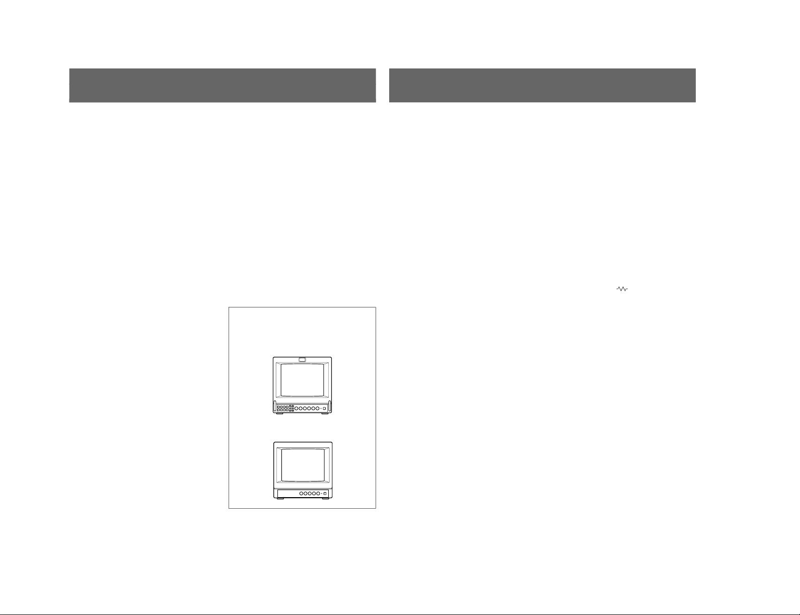
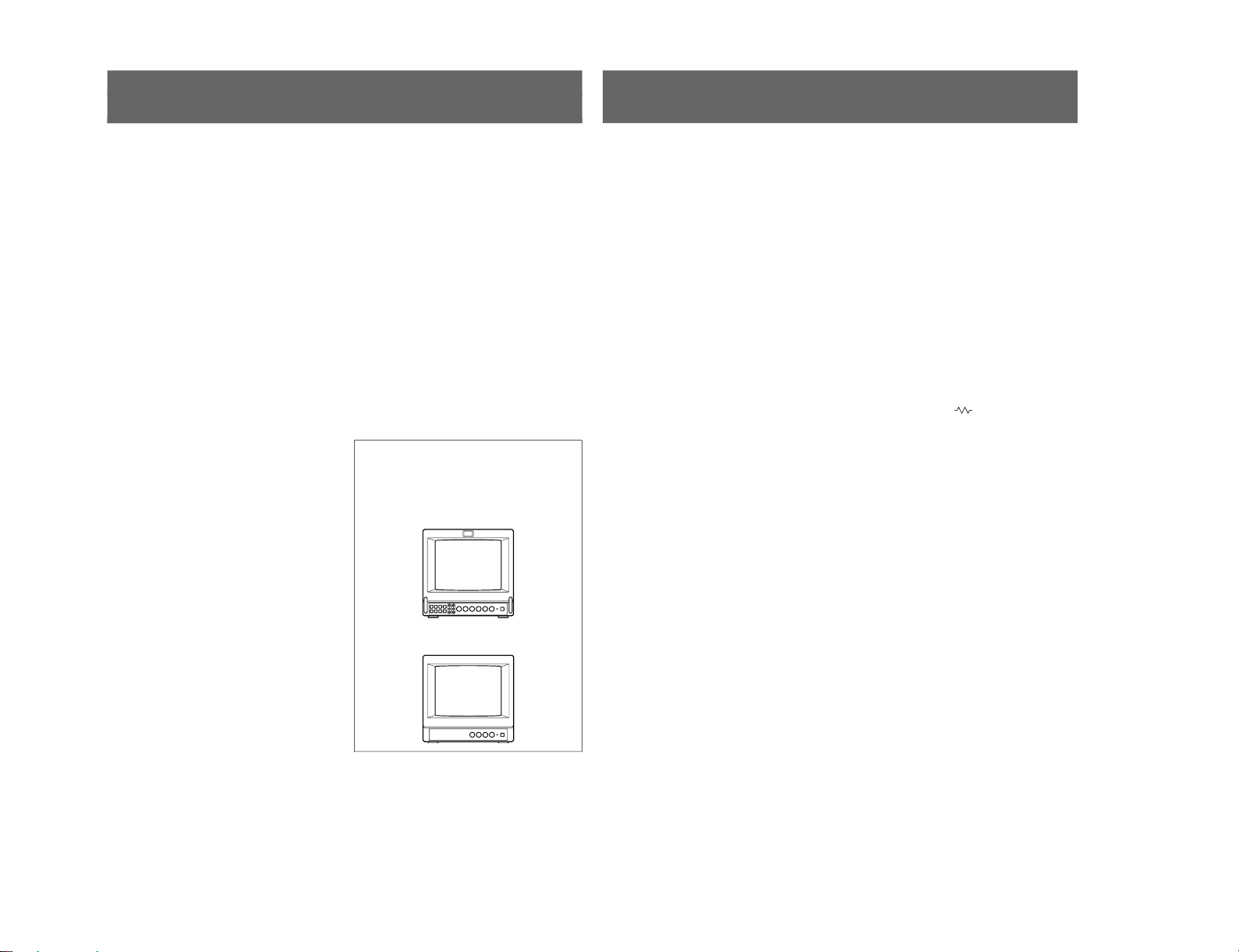
This instruction manual covers the PVM-8045Q,
PVM-8042Q and PVM-8040. The differences
among the models are clearly described in the text.
PVM-8045Q/8042Q
PVM-8040
5
(US)
Four color systems available
(PVM-8045Q/8042Q only)
The monitor can display NTSC, PAL, SECAM and
NTSC
4.43
1)
signals. The appropriate color system is
selected automatically.
HR (High Resolution) Trinitron
® 2)
picture tube
(PVM-8045Q)
The HR Trinitron picture tube (0.25 mm aperture grill
pitch) provides a high resolution picture. Horizontal
resolution is more than 450 TV lines at the center of
the picture.
Trinitron picture tube (PVM-8042Q/8040)
The Trinitron picture tube (0.5mm aperture grill pitch)
provides a high resolution picture. Horizontal
resolution is more than 250 TV lines at the center of
the picture.
Beam current feedback circuit
The built-in beam current feedback circuit assures
stable white balance.
Comb filter
When NTSC video signals are received, a comb filter
activates to increase the resolution, resulting fine
picture detail without color spill or color noise.
Multiple input signals (PVM-8045Q/8042Q only)
In addition to the composite video signals and the Y/C
signals, analog RGB signals and component signals
can be input.
External sync input (PVM-8045Q/8042Q only)
When the EXT SYNC button is pressed, the monitor
can be operated on the sync signal fed through an
external sync connector.
Blue only picture (PVM-8045Q/8042Q only)
Black and white apparent picture consisting from only
the blue signal will be displayed. This facilitates the
“chroma” and “phase” adjustment, and the observation
of the video noise.
16:9 selector (PVM-8045Q/8042Q only)
The monitor can display the 16:9 signal with the
correct ratio of width and height, compressing the
picture vertically.
Under scan mode (PVM-8045Q/8042Q only)
The monitor can display signals that are scanned
outside the normal screen so you can monitor the
whole image.
Audio circuit and built-in speaker
A speaker (0.5 W, monaural) is built into the monitor
for sound monitoring.
Automatic/Manual DEGAUSS
The screen is automatically demagnetized when the
monitor is turned on. Manual degauss is also available
for PVM-8045Q/8042Q by pressing the DEGAUSS
button.
Automatic termination
(only connectors marked
)
The Y/C, VIDEO IN and EXT SYNC IN connectors
are terminated at 75 ohms inside, when no cable is
connected to the loop-through output connectors.
When a cable is connected to an output connector, the
75-ohm termination is automatically released.
EIA standard 19-inch rack mounting
By using an MB-507 mounting bracket (not supplied),
the monitor can be mounted in an EIA standard 19inch rack. For details on mounting, see the instruction
manual of the MB-507.
Varied power sources
In addition to AC power, you can use battery pack or
external DC 12 V power. The monitor can operate with
one or two Sony NP-1B* battery packs. If you use the
DC-L10* battery adaptor, the monitor can operate with
a Sony BP-L60A/L90A* lithium ion battery pack.
* The NP-1B battery pack, DC-L10 battery adaptor
and BP-L60A/L90A battery pack are not supplied.
1) An NTSC
4.43
signal is used for playing back NTSC-recorded video cassettes with a video tape recorder/player especially
designed for use with this system.
2) Trinitron is a trademark of Sony Corporation.
..........................................................................................................................................................................................................
Features
1-3
1-4
7
(US)
!º SYNC INT/EXT (sync internal/external) selector
Keep this button released (INT) to operate the monitor
on the sync signal from the displayed composite video
signal.
Depress this button (EXT) to operate the monitor on an
external sync signal fed through the EXT SYNC
connector on the rear panel.
!¡ LINE/RGB input selector
Select the programme to be monitored. Keep this
button released (LINE) for a signal fed through the
LINE A or LINE B connectors. Depress this button
(RGB) for a signal fed through the RGB connectors.
!™ A/B, RGB/Y R-Y B-Y input selector
When the LINE/RGB input selector is set to LINE,
keep this button released (A) for a signal fed through
the LINE A connectors. Press this button (B) to
monitor the signals from the LINE B connector.
When the LINE/RGB input selector is set to RGB,
select the RGB signal or the component signal which
is fed through the RGB input connectors. Keep this
button released (RGB) for the RGB signal. Press this
button (Y R-Y B-Y) to monitor the component signals.
!£ BLUE ONLY selector
Depress this button to turn off the red and green
signals. A blue signal is displayed as an apparent
monochrome picture on the screen. This facilitates
“chroma” and “phase” control adjustments and the
observation of video noise.
Note
The PHASE control adjustments is effective only for
the NTSC system.
!¢ UNDER SCAN selector
Depress this button for underscanning. The display
size is reduced by approximately 3% so that four
corners of the picture are visible.
!∞ H/V DELAY selector
Depress this button to observe the horizontal and
vertical sync signals at the same time. The horizontal
sync signal is displayed in the left quarter of the
screen; the vertical sync signal is displayed near the
center of the screen.
!§ 16:9 selector
Press this selector to monitor the signals of 16:9
picture.
Pressing the UNDER SCAN selector !¢ in 16:9 mode
displays the whole 16:9 picture up to the four corners.
!¶ R/G/B BIAS and GAIN adjustment controls
Used for white balance fine adjustment.
BIAS and GAIN controls are provided for the R (red),
G (green) and B (blue) screens.
BIAS: Adjust the white balance and brightness of the
screen at the lowlight.
GAIN: Adjust the white balance and brightness of
the screen at the highlight.
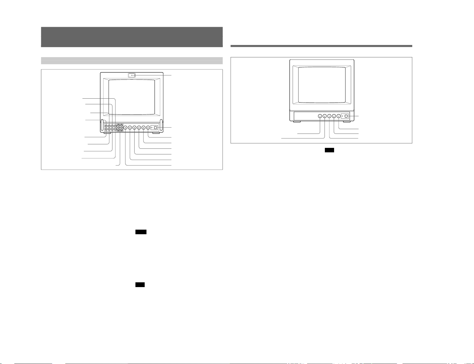
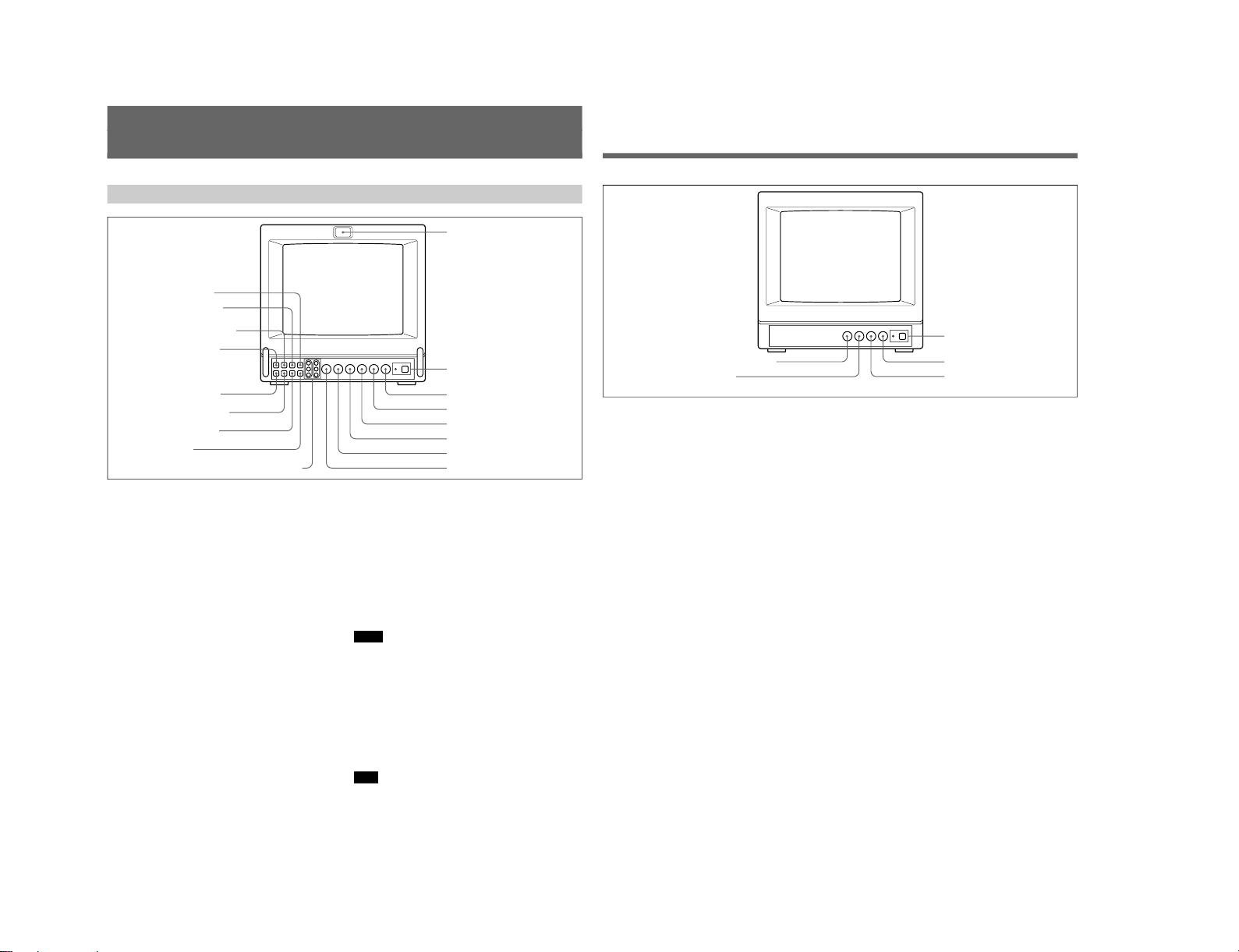
PVM-8040
2 POWER switch and indicator
3 VOLUME control
4 CONTR (contrast) control
6 CHROMA control
5 PHASE control
7 BRIGHT (brightness) control
6
(US)
Location and Function of Parts and Controls
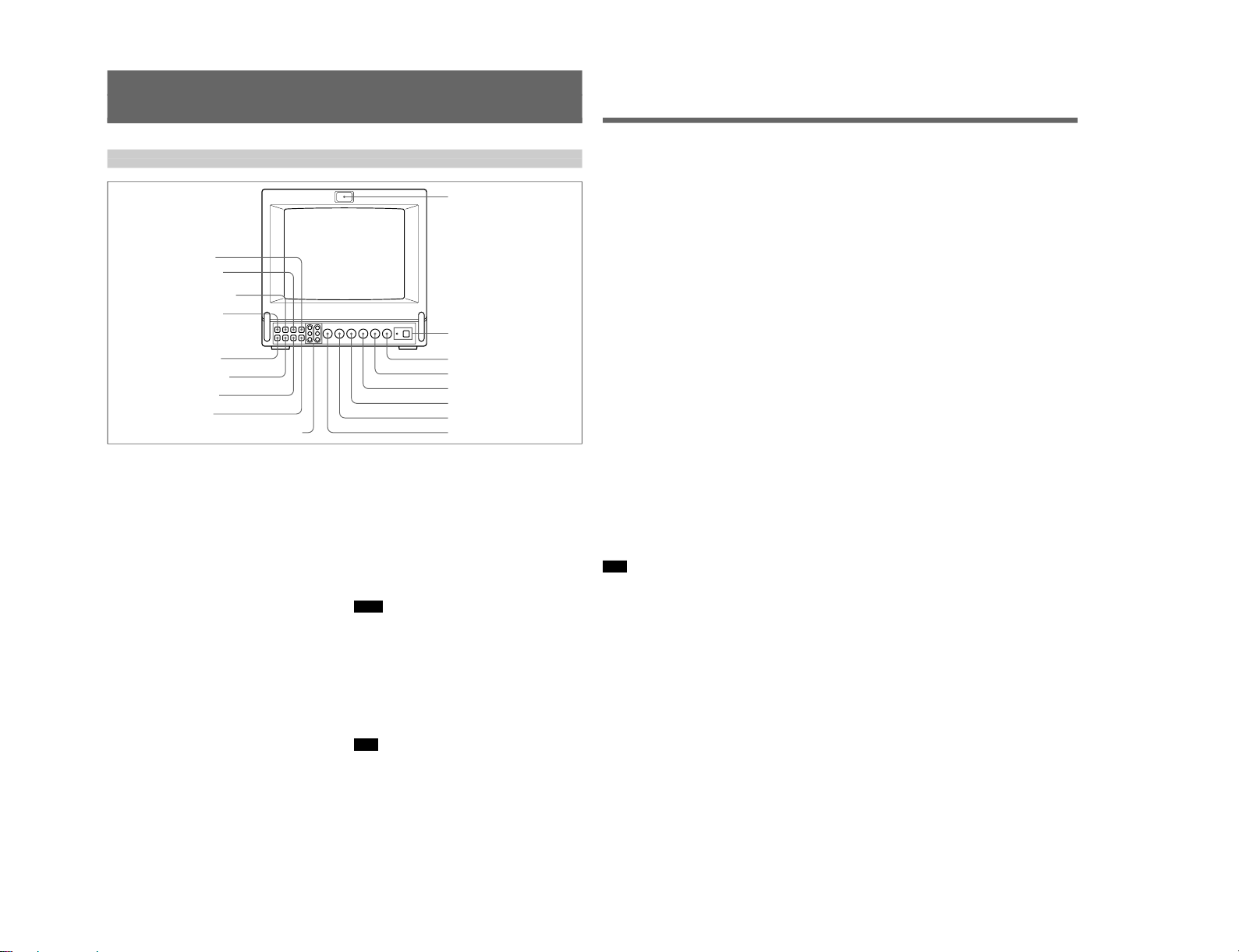
Front
PVM-8045Q/8042Q
1 Tally lamp
This indicator lights up. The tally control connection is
needed.
For the pin assignment, see “Specificatons” on page
12 (US).
2 POWER switch and indicator
Depress to turn the monitor on. The indicator will light
up in green.
The POWER indicator also functions as the battery
indicator. When the internal battery becomes weak or
the power supplied through the DC 12 V IN jack
decreases, the indicator flashes.
3 VOLUME control
Turn this control clockwise or counterclockwise to
obtain the desired volume.
4 CONTR (contrast) control
Turn clockwise to make the contrast stronger and
counterclockwise to make it weaker.
5 PHASE control
This control is effective only for the NTSC and
NTSC
4.43
color systems. Turn clockwise to make the
skin tones greenish and counterclockwise to make
them purplish.
6 CHROMA control
Turn clockwise to make the colour intensity stronger
and counterclockwise to make it weaker.
7 BRIGHT (brightness) control
Turn clockwise for more brightness and
counterclockwise for less.
8 APER (aperture) control
Turn clockwise for more sharpness and
counterclockwise for less.
Notes
•The PHASE, CHROMA and APER control settings
have no effect on an analog RGB signal.
•The PHASE control has no effect on component
signals.
•The PHASE control setting is effective only for the
NTSC system.
9 DEGAUSS button
Press this button momentarily. The screen will be
demagnetized.
Note
If you press the DEGAUSS button again too soon, the
color shades may be uneven.
1 Tally lamp
2 POWER switch and indicator
3 VOLUME control
4 CONTR (contrast) control
5 PHASE control
6 CHROMA control
7 BRIGHT (brightness) control
8 APER (aperture) control
9 DEGAUSS button
!§ 16:9 selector
!º SYNC INT/EXT (sync
internal/external) selector
!¶ R/G/B BIAS and GAIN adjustment controls
!∞ H/V DELAY selector
!£ BLUE ONLY selector
!¢ UNDER SCAN selector
!¡ LINE/RGB input selector
!™ A/B, RGB/Y R-Y B-Y
input selector
S MIC Chassis
S MIC Chassis
8
(US)
Location and Function of Parts and Controls
!• LINE A connectors (PVM-8045Q/8042Q)
!• LINE connectors (PVM-8040)
Y/C IN (4-pin mini DIN): Connect to the Y/C
separate output of a video camera, VCR or other
video equipment.
Y/C OUT (4-pin mini DIN): Loop-through output of
the Y/C IN connector. Connect to the Y/C separate
input of a VCR or another monitor.
VIDEO IN (BNC): Connect to the video output of a
video camera, VCR or other video equipment.
VIDEO OUT (BNC): Loop-through output of the
VIDEO IN connector. Connect to the video input
of a VCR or another monitor.
AUDIO IN (phono jack): Connect to the audio
output of a VCR or a microphone (through a
suitable microphone amplifier).
AUDIO OUT (phono jack): Loop-through output of
the AUDIO IN connector. Connect to the audio
input of a VCR or another monitor.
Note
The Y/C IN connector has a priority over the VIDEO
IN connector.
When a plug is connected to the Y/C IN connector, the
VIDEO IN connector is automatically disconnected.
Note
(PVM-8045Q/8042Q only)
To monitor the signal fed through these connectors,
keep the LINE/RGB selector and the A/B, RGB/Y R-Y
B-Y selector on the front panel released (LINE and A).
!ª LINE B connectors
To monitor the signal fed through these connectors,
keep the LINE/RGB selector released (LINE) and
depress the A/B, RGB/Y R-Y B-Y selector on the front
panel (B).
VIDEO IN (BNC): Connect to the video output of a
video camera, VCR or other video equipment.
VIDEO OUT (BNC): Loop-through output of the
VIDEO IN connector. Connect to the video input
of a VCR or another monitor.
AUDIO IN (phono jack): Connect to the audio
output of a VCR or a microphone (through a
suitable microphone amplifier).
AUDIO OUT (phono jack): Loop-through output of
the AUDIO IN connector. Connect to the audio
input of a VCR or another monitor.
@º REMOTE connector (8-pin mini DIN)
Connect to the tally output of a control console,
special-effect generator, etc. The tally lamp on the
front panel will be turned on and off by the connected
equipment. This connector can be used for connecting
a remote controller.
For the pin assignment of this connector, see
“Specifications” on page 12 (US).
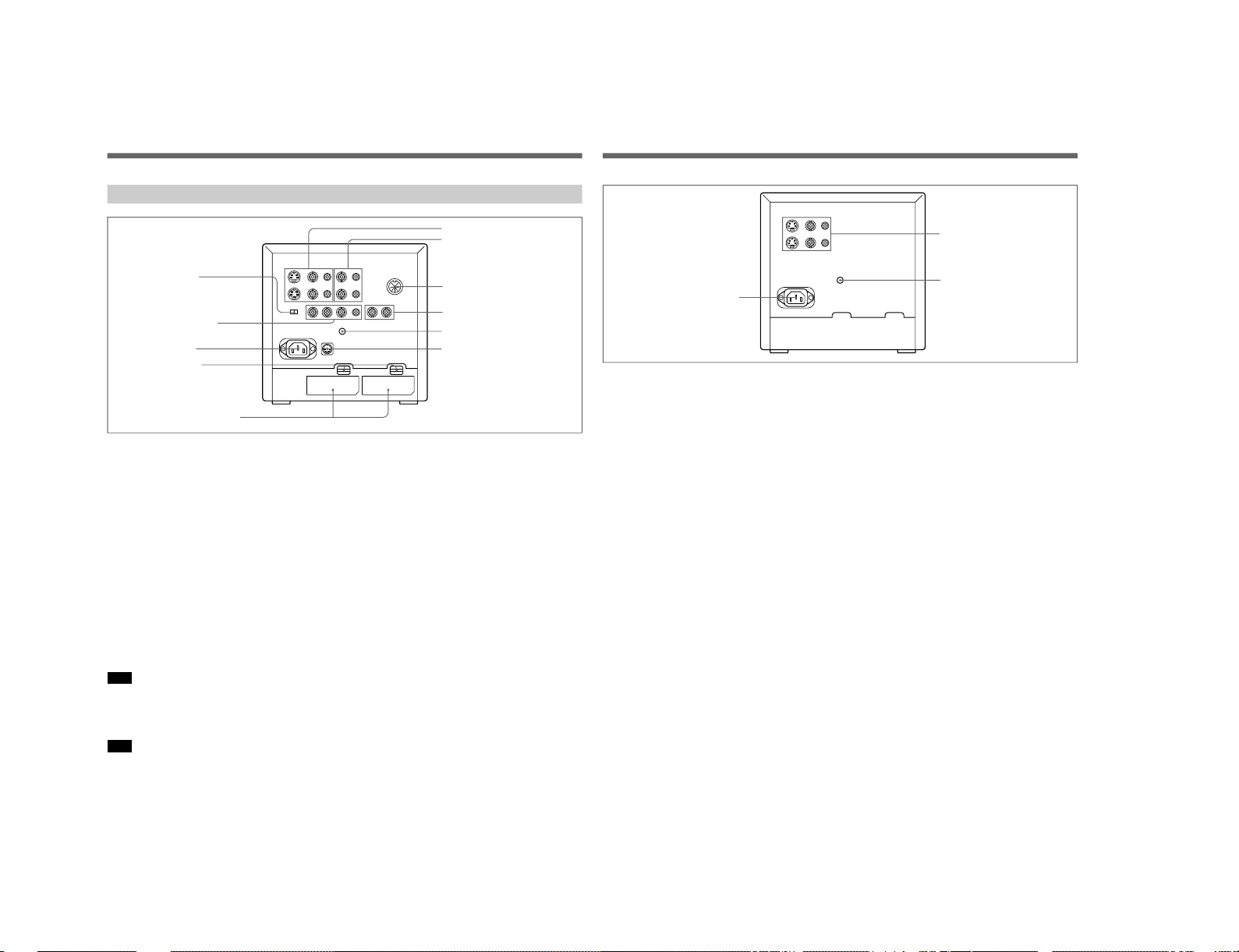
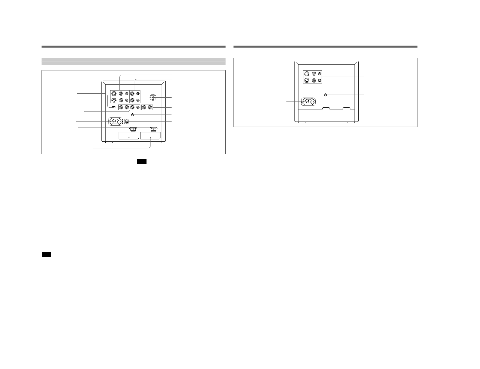
Rear
PVM-8045Q/8042Q
!• LINE A connectors
!ª LINE B connectors
@º REMOTE connector
(8-pin mini DIN)
@¡ EXT SYNC (external sync)
connectors
@™ V HOLD (vertical hold) control
@£ DC 12V IN jack (XLR, 4 pin)
@¢ COMPONENT
LEVEL selector
@∞ RGB/COMPONENT
input connectors
@§ AC IN socket
@¶ EJECT buttons
@• BATTERY compartments
9
(US)
@¡ EXT SYNC (external sync) connectors
IN (BNC): When this monitor operates on an
external sync signal, connect the reference signal
from a sync generator to this connector. In this
case, depress the SYNC INT/EXT selector on the
front panel (EXT).
OUT (BNC): Loop-through output of the EXT
SYCN IN connector. Connect to the external sync
input of video equipment to be synchronized with
this monitor.
@™ V HOLD (vertical hold) control
Turn to stabilize the picture if it rolls vertically.
@£ DC 12V IN jack (XLR, 4 pin)
Connect the Sony battery adaptor DC-L10 (not
supplied).
@¢ COMPONENT LEVEL selector
Select the component level from among two modes.
N10/SMPTE: for 100/0/100/0 signal
BETA 0: for 100/0/75/0 signal
@∞ RGB/COMPONENT input connectors
R/R-Y, G/Y, B/B-Y (BNC), AUDIO (phono):
To monitor a signal fed through these connectors,
depress the LINE/RGB selector on the front panel
(RGB). When the SYNC INT/EXT selector on the
front paner is released (INT), the monitor operates on
the sync signal from the G/Y channel.
PVM-8040
To monitor the analog RGB signal
Connect to the analog RGB signal outputs of a video
camera. Keep the A/B, RGB/Y R-Y B-Y selector on
the front panel released (RGB).
To monitor the component signal
Connect to the R-Y/Y/B-Y componenet signal outputs
of a Sony BetaCam video camera. Depress the A/B,
RGB/Y R-Y B-Y selector on the front panel (Y R-Y BY).
@§ AC IN socket
Connect the supplied AC power cord to this socket and
to a wall outlet.
@¶ EJECT buttons
Press the EJECT button upwards to remove the battery
pack.
@• BATTERY compartments
Insert the NP-1B battery pack (not supplied).
!• LINE connectors
@™ V HOLD (vertical hold)
control
@§ AC IN socket
1-5
1-6
11
(US)
Specifications
Video signal
Colour system PVM-8045Q/8042Q: NTSC,
PAL, SECAM, NTSC
4.43
PVM-8040: NTSC
Resolution PVM-8045Q: 450 TV lines
PVM-8042Q/8040: 250 TV lines
Aperture correction –4.0 dB to +6.0 dB (at 3.0 MHz)
Frequency response 6.0 MHz (–3.0 dB) at all inputs
Synchronization AFC time constant 1.0 msec.
Picture performance
Normal scan 6% over scan of CRT effective
screen area
Underscan 3% underscan of CRT effective
screen area
H. linearity Less than 5.0% (typical)
V. linearity Less than 5.0% (typical)
Convergence Central area: 0.43 mm (typical)
Peripheral area: 0.53 mm
(typical)
Raster size stability H: 1.0%, V: 1.5%
High voltage regulation
3.0%
Color temperature D65
Inputs and Outputs
Model PVM-8045Q PVM-8040
Connector PVM-8042Q
LINE A Y/C IN yes yes
Y/C OUT yes yes
VIDEO IN yes yes
VIDEO OUT yes yes
AUDIO IN yes yes
AUDIO OUT yes yes
LINE B VIDEO IN yes no
VIDEO OUT yes no
AUDIO IN yes no
AUDIO OUT yes no
RGB/ R/R-Y IN yes no
COMPONENT G/Y IN yes no
B/B-Y IN yes no
AUDIO IN yes no
EXT SYNC IN yes no
OUT yes no
REMOTE yes no
Inputs Y/C IN: 4-pin mini DIN
connector
See the pin assignment on page
12 (US).
VIDEO IN: BNC connector
1 Vp-p ± 6 dB, sync negative
AUDIO IN: phono jack, –5 dBu
a)
,
less than 47 kohms
R/R-Y, G/Y, B/B-Y: BNC
connector
R, G, B channels: 0.7 Vp-p,
± 6 dB Sync on green: 0.3 Vp-p,
negative,
R-Y, Y, B-Y channels: 0.7 Vp-p,
±6 dB (Standard colour bar
signal of 75% chrominance)
EXT SYNC IN: BNC connector
Composite sync 4 Vp-p, ±6 dB,
negative
Loop-through outputs
Y/C OUT: 4-pin mini DIN
connector, 75 ohms terminated
(75 ohms automatic termination)
VIDEO OUT: BNC connector,
75 ohms terminated (75 ohms
automatic termination)
AUDIO OUT: phono jack
EXT SYNC OUT: BNC
connector, 75 ohms terminated
Speaker output Output level 0.5 W
Remote input REMOTE: 8-pin mini DIN
connctor (75 ohms automatic
termination)
See the pin assignment on page
12 (US).
a) 0 dBu = 0.775 Vr.m.s.
General
Power consumption & requirements
PVM-8045Q/8042Q:
0.6 A 45 W MAX at 120 V AC
operation
3.7 A 38 W at 12 V DC operation
PVM-8040:
0.6 A 39 W MAX at 120 V AC
operation
Operating conditions
Temperature 0 to +35°C (32 to 95°F)
Humidity 0 to 90% (no condensation)
Pressure 700 to 1060 hPa
10
(US)
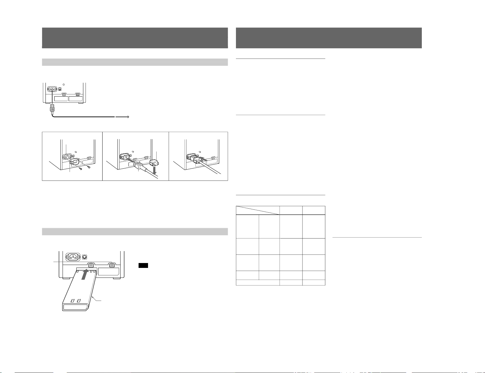
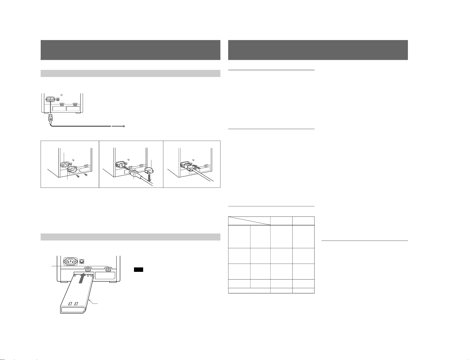
Power Sources
Connect the supplied AC power cord to the AC IN
socket and to a wall outlet.
1
Remove the AC IN socket screws and then use
them to attach the AC plug holder A (supplied) to
the AC IN socket.
2
Plug the power cord to the AC IN sokcet. Then,
attach the supplied AC plug holder B on top of the
AC power cord.
The monitor can operate with one or two battery packs.
For extended use, two battery packs are recommended.
House Current (for all models)
to AC IN
to a wall outlet
For the PVM-8045Q/8042Q
When the AC power cord is plugged into the AC IN
socket, the battery pack (if installed) or the AC power
adaptor (if connected) is automatically disconnected.
To connect an AC power cord securely with AC plug holders.
3
21
AC IN socket
AC plug holder A
AC power plug
AC plug
holder B
3
Slide AC plug holder B over the cord until is locks.
To remove the AC power cord
Pull out AC plug holder B by squeezing the left and
right sides.
Rechargeable Battery (PVM-8045Q/8042Q only)
To remove the battery pack, press the EJECT button
upwards.
For charging, use the BC-1WD for the NP-1B.
Note
Make sure you disconnect the cables connected to the
connectors (AC IN, DC 12 V IN) at the rear of the
monitor. Otherwise, the monitor cannot operate on the
battery pack(s).
SONY mark downwards
EJECT
buttons
NP-1B
(not supplied)
S MIC Chassis
S MIC Chassis
12
(US)
Transport and storage conditions
Temperature –10 to +40°C (14 to 104°F)
Humidity 0 to 90%
Pressure 700 to 1060 hPa
Dimensions Approx. 217 x 217 x 352.5 mm
(w/h/d) (8
5
/
8
× 8 5/8 × 14 inches)
not incl. projecting parts and
controls
Mass Approx. 8.2 kg (18 lb 1 oz) not
incl. battery packs
Accessory supplied AC power cord (1)
Cable with an 8-pin connector (1)
(PVM-8045Q/8042Q only)
AC plug holders (1 set)
Tally plate (1) (PVM-8045Q/
8042Q only)
Design and specifications are subject to change
without notice.
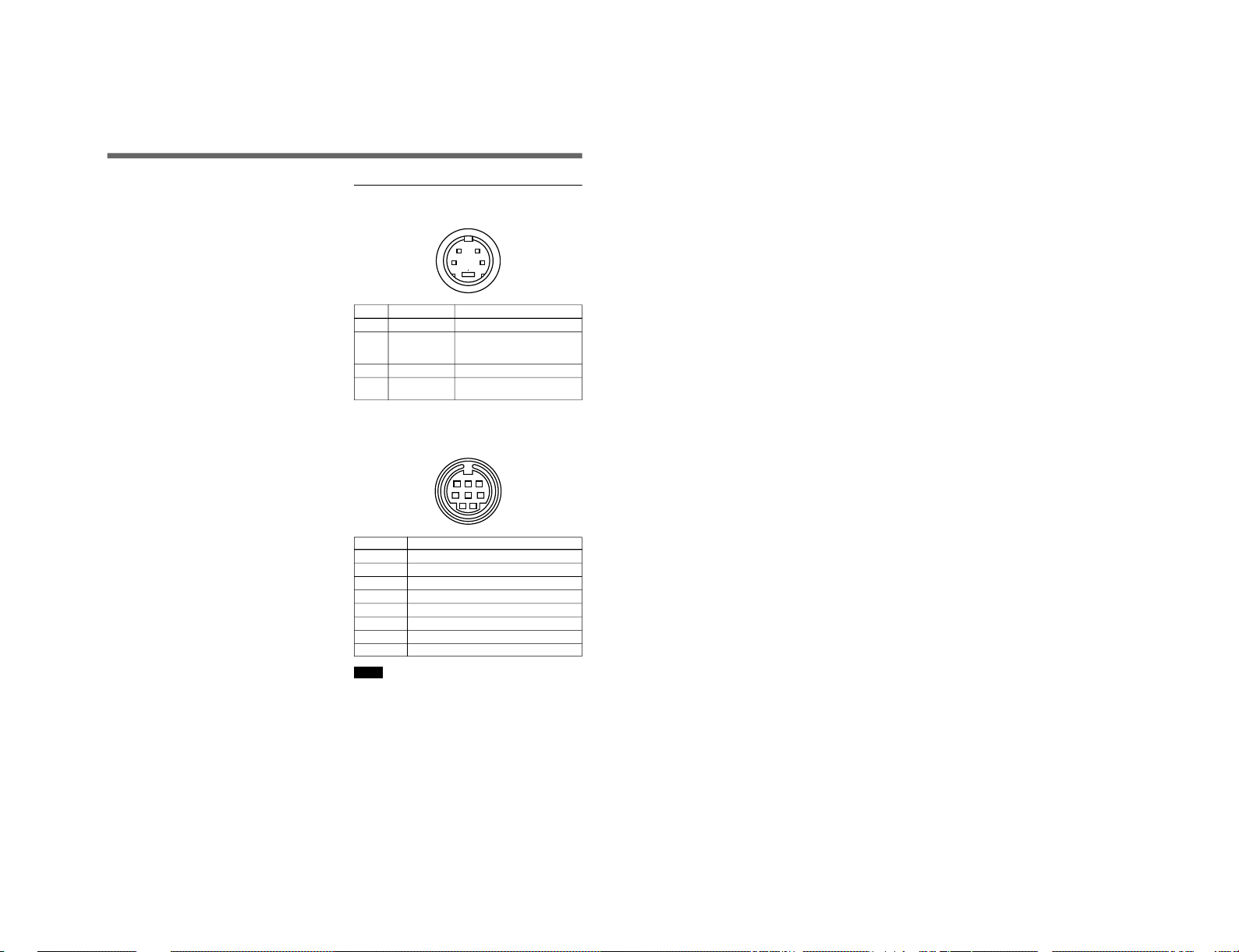
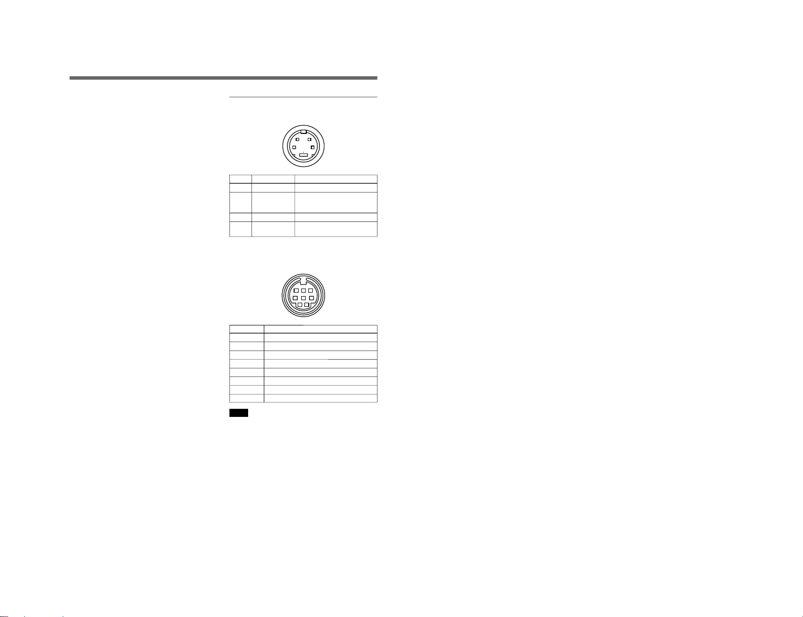
Pin Assignment
Y/C IN connector (4-pin mini DIN)
12
43
Pin No. Signal Description
1 Y-input 1 Vp-p, sync negative, 75 ohms
2 CHROMA 286 mVp-p (NTSC), burst
sub-carrier-input Delay time between Y and
C: within 0 ±100 nsec., 75 ohms
3 GND for Y-input GND
4 GND for
GND
CHROMA-input
REMOTE connector (8-pin mini DIN)
(PVM-8045Q/8042Q only)
12
3
678
45
Pin No. Signal
1 16:9
2 H/V delay
3 GND
4 EXT SYNC
5 Tally
6 Underscan
7 A/B or RGB/Y R-Y B-Y
8 LINE/RGB
Notes
•For remote control, connect the pin of the desired
function to pin 3 (GND).
•For remote control, set the front button to OFF (the
switch is out).
Specifications
1-7
1-8
3-865-058-21 (1)
1
(EN)
PVM-9045QM PVM-9042QM
PVM-9040ME
Operating Instructions
Mode d’emploi
Bedienungsanleitung
Manual de instrucciones
Istruzioni per l’uso
XXXXX
FR
DE
Trinitr on
®
Color Video Monitor
GB
ES
IT
CS
1998 by Sony Corporation
S MIC Chassis
S MIC Chassis
2
(GB)
English
WARNING
To prevent fire or shock hazard, do not
expose the unit to rain or moisture.
Dangerously high voltages are present inside
the unit. Do not open the cabinet. Refer
servicing to qualified personnel only.
In the event of a malfunction or when
maintenance is necessary, consult an authorized
Sony dealer.
THIS APPARATUS MUST BE EARTHED
For the customers in the UNITED KINGDOM
IMPORTANT
The wires in this mains lead are coloured in accordance with
the following code:
Green-and-yellow : Earth
Blue : Neutral
Brown : Live
As the colours of the wires in the mains lead of this
apparatus may not correspond with the coloured markings
identifying the terminals in your plug proceed as follows:
The wire which is coloured green-and-yellow must be
connected to the terminal in the plug which is marked with
the letter E or by the safety earth symbol Y or coloured
green or green-and-yellow.
The wire which is coloured blue must be connected to the
terminal which is marked with the letter N or coloured black.
The wire which is coloured brown must be connected to the
terminal which is marked with the letter L or coloured red.
Ensure that your equipment is connected
correctly.
If you are in any doubt consult a qualified
electrician.
CAUTION:
Danger of explosion if battery is incorrectly replaced.
Replace only with the same or equivalent type recommended
by the manufacturer. Discard used batteries according to the
manufacturer’s instructions.
Voor de klanten in Nederland
Bij dit produkt zijn batterijen geleverd.
Wanneer deze leeg zijn, moet u ze niet
weggooien maar inleveren als KCA.
3
(GB)
English
GB
On safety
•PVM-9045QM/9042QM: Operate the unit on 100 -
240 V AC or 12 V DC. For the AC operation, use
only the supplied AC power cord or the AC power
adaptor recommended (not supplied). Do not use any
other type.
For the battery operation, use only the NP-1B battery
pack and BP-L60A/L90A with DC-L10 (not
supplied). Do not use any other batteries.
•PVM-9040ME: Operate the unit only on 100 - 240 V
AC. Use only the supplied AC power cord. Do not
use any other type.
•Should any liquid or solid object fall into the cabinet,
unplug the unit and have it checked by qualified
personnel before operating it further.
•Unplug the unit from the wall outlet if it is not to be
used for several days.
•To disconnect the AC power cord, pull it out by the
plug. Never pull the cord itself.
On installation
•Allow adequate air circulation to prevent internal heat
build-up. Do not place the unit on surfaces (rugs,
blankets, etc.) or near materials (curtains, draperies)
that may block the ventilation holes.
•Do not install the unit near heat sources such as
radiators or air ducts, or in a place subject to direct
sunlight, excessive dust, mechanical vibration or
shock.
•Keep the unit away from a loudspeaker or motor, as
the picture may be affected.
On cleaning
Clean the unit with a slightly dampened soft cloth. Use
a mild household detergent. Never use strong solvents
such as thinner or benzine as they might damage the
finish of the cabinet.
As a safety precaution, unplug the unit before cleaning
it.
On repacking
Retain the original carton and packing materials for
safe transport of this unit in the future.
If you have any questions about this unit, contact your
authorized Sony dealer.
A TTENTION –
When the product is
installed in a rack:
a) Elevated operating ambient temperature
If installed in a closed or multi-unit rack assembly,
the operating ambient temperature of the rack
environment may be greater than room ambient.
Therefore, consideration should be given to
installing the equipment in an environment
compatible with the manufacturer’s maximum rated
ambient temperature of 0 to +35°C (32 to 95°F)
(Tmra).
b) Reduced air flow
Installation of the equipment in a rack should be
such that the amount of air flow required for safe
operation of the equipment is not compromised.
c) Mechanical loading
Mounting of the equipment in the rack should be
such that a hazardous condition is not achieved due
to uneven mechanical loading.
d) Circuit overloading
Consideration should be given to the connection of
the equipment to the supply circuit and the effect
that overloading of circuits might have on
overcurrent protection and supply wiring.
Appropriate consideration of equipment nameplate
ratings should be used when addressing this
concern.
e) Reliable earthing
Reliable earthing of rack-mounted equipment
should be maintained. Particular attention should be
given to supply connections other than direct
connections to the branch circuit (e.g., use of power
strips).
f) Gap keeping
The upper and lower gaps of rack-mounted
equipment should be least 44 mm (1
3
/4 inches).
Precautions
1-9
1-10
4
(GB)
Table of Contents
Features.............................................................................. 5
Location and function
of parts and controls .................................................... 6
Front...................................................................................6
Rear .................................................................................... 8
Power sources ................................................................. 10
Specifications .................................................................. 11
This instruction manual covers the PVM-9045QM,
PVM-9042QM and PVM-9040ME.
The differences among the models are clearly
described in the text.
PVM-9045QM/9042QM
PVM-9040ME
5
(GB)
Four colour systems available
(PVM-9045QM/9042QM only)
The monitor can display PAL, SECAM, NTSC and
NTSC
4.43
1)
signals. The appropriate colour system is
selected automatically.
HR (High Resolution) Trinitron
® 2)
picture tube
(PVM-9045QM)
The HR Trinitron picture tube (0.25 mm aperture grill
pitch) provides a high resolution picture. Horizontal
resolution is more than 450 TV lines at the center of
the picture.
Trinitron picture tube (PVM-9042QM/9040ME)
The Trinitron picture tube (0.5mm aperture grill pitch)
provides a high resolution picture. Horizontal
resolution is more than 250 TV lines at the center of
the picture.
Beam current feedback circuit
The built-in beam current feedback circuit assures
stable white balance.
Multiple input signals
(PVM-9045QM/9042QM only)
In addition to the composite video signals and the Y/C
signals, analog RGB signals and component signals
can be input.
External sync input
(PVM-9045QM/9042QM only)
When the EXT SYNC button is pressed, the monitor
can be operated on the sync signal fed through an
external sync connector.
Blue only picture (PVM-9045QM/9042QM only)
Black and white apparent picture consisting from only
the blue signal will be displayed. This facilitates the
chroma adjustment, and the observation of the video
noise.
16:9 selector (PVM-9045QM/9042QM only)
The monitor can display the 16:9 signal with the
correct ratio of width and height, compressing the
picture vertically.
Under scan mode (PVM-9045QM/9042QM only)
The monitor can display signals that are scanned
outside the normal screen so you can monitor the
whole image.
Audio circuit and built-in speaker
A speaker (0.5 W, monaural) is built into the monitor
for sound monitoring.
Automatic/Manual DEGAUSS
The screen is automatically demagnetized when the
monitor is turned on. Manual degauss is also available
for PVM-9045QM/9042QM by pressing the
DEGAUSS button.
Automatic termination
(only connectors marked
)
The Y/C, VIDEO IN and EXT SYNC IN connectors
are terminated at 75 ohms inside, when no cable is
connected to the loop-through output connectors.
When a cable is connected to an output connector, the
75-ohm termination is automatically released.
EIA standard 19-inch rack mounting
By using an MB-507 mounting bracket (not supplied),
the monitor can be mounted in an EIA standard 19inch rack. For details on mounting, see the instruction
manual of the MB-507.
Varied power sources
In addition to AC power, you can use battery pack or
external DC 12 V power. The monitor can operate with
one or two Sony NP-1B* battery packs. If you use the
DC-L10* battery adaptor, the monitor can operate with
a Sony BP-L60A/L90A* lithium ion battery pack.
* The NP-1B battery pack, DC-L10 battery adaptor
and BP-L60A/L90A battery pack are not supplied.
1) An NTSC
4.43
signal is used for playing back NTSC-recorded video cassettes with a video tape recorder/player especially
designed for use with this system.
2) Trinitron is a trademark of Sony Corporation.
..........................................................................................................................................................................................................
Features
S MIC Chassis
S MIC Chassis
6
(GB)
Location and Function of Parts and Controls
Front
PVM-9045QM/9042QM
1 Tally lamp
This indicator lights up. The tally control connection is
needed.
For the pin assignment, see “Specificatons” on page
12 (GB).
2 POWER switch and indicator
Depress to turn the monitor on. The indicator will light
up in green.
The POWER indicator also functions as the battery
indicator. When the internal battery becomes weak or
the power supplied through the DC 12 V IN jack
decreases, the indicator flashes.
3 VOLUME control
Turn this control clockwise or counterclockwise to
obtain the desired volume.
4 CONTR (contrast) control
Turn clockwise to make the contrast stronger and
counterclockwise to make it weaker.
5 PHASE control
This control is effective only for the NTSC and
NTSC
4.43
colour systems. Turn clockwise to make the
skin tones greenish and counterclockwise to make
them purplish.
6 CHROMA control
Turn clockwise to make the colour intensity stronger
and counterclockwise to make it weaker.
7 BRIGHT (brightness) control
Turn clockwise for more brightness and
counterclockwise for less.
8 APER (aperture) control
Turn clockwise for more sharpness and
counterclockwise for less.
Notes
•The PHASE, CHROMA and APER control settings
have no effect on an analog RGB signal.
•The PHASE control has no effect on component
signals.
•The PHASE control setting is effective only for the
NTSC system.
9 DEGAUSS button
Press this button momentarily. The screen will be
demagnetized.
Note
If you press the DEGAUSS button again too soon, the
color shades may be uneven.
1 Tally lamp
2 POWER switch and indicator
3 VOLUME control
4 CONTR (contrast) control
5 PHASE control
6 CHROMA control
7 BRIGHT (brightness) control
8 APER (aperture) control
9 DEGAUSS button
!§ 16:9 selector
!º SYNC INT/EXT (sync
internal/external) selector
!¶ R/G/B BIAS and GAIN adjustment controls
!∞ H/V DELAY selector
!£ BLUE ONLY selector
!¢ UNDER SCAN selector
!¡ LINE/RGB input selector
!™ A/B, RGB/Y R-Y B-Y
input selector
7
(GB)
!º SYNC INT/EXT (sync internal/external) selector
Keep this button released (INT) to operate the monitor
on the sync signal from the displayed composite video
signal.
Depress this button (EXT) to operate the monitor on an
external sync signal fed through the EXT SYNC
connector on the rear panel.
!¡ LINE/RGB input selector
Select the programme to be monitored. Keep this
button released (LINE) for a signal fed through the
LINE A or LINE B connectors. Depress this button
(RGB) for a signal fed through the RGB connectors.
!™ A/B, RGB/Y R-Y B-Y input selector
When the LINE/RGB input selector is set to LINE,
keep this button released (A) for a signal fed through
the LINE A connectors. Press this button (B) to
monitor the signals from the LINE B connectors.
When the LINE/RGB input selector is set to RGB,
select the RGB signal or the component signal which
is fed through the RGB input connectors. Keep this
button released (RGB) for the RGB signal. Press this
button (Y R-Y B-Y) to monitor the component signals.
!£ BLUE ONLY selector
Depress this button to turn off the red and green
signals. A blue signal is displayed as an apparent
monochrome picture on the screen. This facilitates
“chroma” control adjustments and the observation of
video noise.
!¢ UNDER SCAN selector
Depress this button for underscanning. The display
size is reduced by approximately 3% so that four
corners of the picture are visible.
!∞ H/V DELAY selector
Depress this button to observe the horizontal and
vertical sync signals at the same time. The horizontal
sync signal is displayed in the left quarter of the
screen; the vertical sync signal is displayed near the
center of the screen.
!§ 16:9 selector
Press this selector to monitor the signals of 16:9
picture.
Pressing the UNDER SCAN selector !¢ in 16:9 mode
displays the whole 16:9 picture up to the four corners.
!¶ R/G/B BIAS and GAIN adjustment controls
Used for white balance fine adjustment.
BIAS and GAIN controls are provided for the R (red),
G (green) and B (blue) screens.
BIAS: Adjust the white balance and brightness of the
screen at the lowlight.
GAIN: Adjust the white balance and brightness of
the screen at the highlight.
PVM-9040ME
2 POWER switch and indicator
3 VOLUME control
4 CONTR (contrast) control
7 BRIGHT (brightness) control
6 CHROMA control
1-11
1-12
8
(GB)
Location and Function of Parts and Controls
!• LINE A connectors (PVM-9045QM/9042QM)
!• LINE connectors (PVM-9040ME)
Y/C IN (4-pin mini DIN): Connect to the Y/C
separate output of a video camera, VCR or other
video equipment.
Y/C OUT (4-pin mini DIN): Loop-through output of
the Y/C IN connector. Connect to the Y/C separate
input of a VCR or another monitor.
VIDEO IN (BNC): Connect to the video output of a
video camera, VCR or other video equipment.
VIDEO OUT (BNC): Loop-through output of the
VIDEO IN connector. Connect to the video input
of a VCR or another monitor.
AUDIO IN (phono jack): Connect to the audio
output of a VCR or a microphone (through a
suitable microphone amplifier).
AUDIO OUT (phono jack): Loop-through output of
the AUDIO IN connector. Connect to the audio
input of a VCR or another monitor.
Note
The Y/C IN connector has a priority over the VIDEO
IN connector.
When a plug is connected to the Y/C IN connector, the
VIDEO IN connector is automatically disconnected.
Note
(PVM-9045QM/9042QM only)
To monitor the signal fed through these connectors,
keep the LINE/RGB selector and the A/B, RGB/Y R-Y
B-Y selector on the front panel released (LINE and A).
!ª LINE B connectors
To monitor the signal fed through these connectors,
keep the LINE/RGB selector released (LINE) and
depress the A/B, RGB/Y R-Y B-Y selector on the front
panel (B).
VIDEO IN (BNC): Connect to the video output of a
video camera, VCR or other video equipment.
VIDEO OUT (BNC): Loop-through output of the
VIDEO IN connector. Connect to the video input
of a VCR or another monitor.
AUDIO IN (phono jack): Connect to the audio
output of a VCR or a microphone (through a
suitable microphone amplifier).
AUDIO OUT (phono jack): Loop-through output of
the AUDIO IN connector. Connect to the audio
input of a VCR or another monitor.
Rear
PVM-9045QM/9042QM
!• LINE A connectors
!ª LINE B connectors
@º REMOTE connector
(8-pin mini DIN)
@¡ EXT SYNC (external sync)
connectors
@™ V HOLD (vertical hold) control
@£ DC 12V IN jack (XLR, 4 pin)
@¢ COMPONENT
LEVEL selector
@∞ RGB/COMPONENT
input connectors
@§ AC IN socket
@¶ EJECT buttons
@• BATTERY compartments
9
(GB)
@º REMOTE connector (8-pin mini DIN)
Connect to the tally output of a control console,
special-effect generator, etc. The tally lamp on the
front panel will be turned on and off by the connected
equipment. This connector can be used for connecting
a remote controller.
For the pin assignment of this connector, see
“Specifications” on page 12 (GB).
@¡ EXT SYNC (external sync) connectors
IN (BNC): When this monitor operates on an
external sync signal, connect the reference signal
from a sync generator to this connector. In this
case, depress the SYNC INT/EXT selector on the
front panel (EXT).
OUT (BNC): Loop-through output of the EXT
SYCN IN connector. Connect to the external sync
input of video equipment to be synchronized with
this monitor.
@™ V HOLD (vertical hold) control
Turn to stabilize the picture if it rolls vertically.
@£ DC 12V IN jack (XLR, 4 pin)
Connect the Sony battery adaptor DC-L10 (not
supplied).
@¢ COMPONENT LEVEL selector
Select the component level from among two modes.
N10/SMPTE: for 100/0/100/0 signal
BETA 0: for 100/0/75/0 signal
PVM-9040ME
@∞ RGB/COMPONENT input connectors
R/R-Y, G/Y, B/B-Y (BNC), AUDIO (phono):
To monitor a signal fed through these connectors,
depress the LINE/RGB selector on the front panel
(RGB). When the SYNC INT/EXT selector on the
front paner is released (INT), the monitor operates on
the sync signal from the G/Y channel.
To monitor the analog RGB signal
Connect to the analog RGB signal outputs of a video
camera. Keep the A/B, RGB/Y R-Y B-Y selector on
the front panel released (RGB).
To monitor the component signal
Connect to the R-Y/Y/B-Y componenet signal outputs
of a Sony BetaCam video camera. Depress the A/B,
RGB/Y R-Y B-Y selector on the front panel (Y R-Y BY).
@§ AC IN socket
Connect the supplied AC power cord to this socket and
to a wall outlet.
@¶ EJECT buttons
Press the EJECT button upwards to remove the battery
pack.
@• BATTERY compartments
Insert the NP-1B battery pack (not supplied).
!• LINE connectors
@™ V HOLD (vertical hold)
control
@§ AC IN socket
S MIC Chassis
S MIC Chassis
10
(GB)
Power Sources
Connect the supplied AC power cord to the AC IN
socket and to a wall outlet.
1
Remove the AC IN socket screws and then use
them to attach the AC plug holder A (supplied) to
the AC IN socket.
2
Plug the power cord to the AC IN sokcet. Then,
attach the supplied AC plug holder B on top of the
AC power cord.
The monitor can operate with one or two battery packs.
For extended use, two battery packs are recommended.
House Current (for all models)
to AC IN
to a wall outlet
For the PVM-9045QM/9042QM
When the AC power cord is plugged into the AC IN
socket, the battery pack (if installed) or the DC 12 V
IN jack (if connected) is automatically disconnected.
To connect an AC power cord securely with AC plug holders.
3
21
AC IN socket
AC plug holder A
AC power plug
AC plug
holder B
3
Slide AC plug holder B over the cord until is locks.
To remove the AC power cord
Pull out AC plug holder B by squeezing the left and
right sides.
Rechargeable Battery (PVM-9045QM/9042QM only)
To remove the battery pack, press the EJECT button
upwards.
For charging, use the BC-1WDCE for the NP-1B.
Note
Make sure you disconnect the cables connected to the
connectors (AC IN, DC 12 V IN) at the rear of the
monitor. Otherwise, the monitor cannot operate on the
battery pack(s).
SONY mark downwards
EJECT
buttons
NP-1B
(not supplied)
11
(GB)
Specifications
Video signal
Colour system PVM-9045QM/9042QM: PAL,
SECAM, NTSC, NTSC
4.43
PVM-9040ME: PAL, SECAM
Resolution PVM-9045QM: 450 TV lines
PVM-9042QM/9040ME: 250 TV
lines
Aperture correction –4.0 dB to +6.0 dB (at 3.0 MHz)
Frequency response 6.0 MHz (–3.0 dB)
Synchronization AFC time constant 1.0 msec.
Picture performance
Normal scan 6% over scan of CRT effective
screen area
Underscan 3% underscan of CRT effective
screen area
H. linearity Less than 5.0% (typical)
V. linearity Less than 5.0% (typical)
Convergence Central area: 0.43 mm (typical)
Peripheral area: 0.53 mm
(typical)
Raster size stability H: 1.0%, V: 1.5%
High voltage regulation
3.0%
Colour temperature D65
Inputs and Outputs
Model PVM-9045QM PVM-9040ME
Connector PVM-9042QM
LINE A Y/C IN yes yes
Y/C OUT yes yes
VIDEO IN yes yes
VIDEO OUT yes yes
AUDIO IN yes yes
AUDIO OUT yes yes
LINE B VIDEO IN yes no
VIDEO OUT yes no
AUDIO IN yes no
AUDIO OUT yes no
RGB/ R/R-Y IN yes no
COMPONENT G/Y IN yes no
B/B-Y IN yes no
AUDIO IN yes no
EXT SYNC IN yes no
OUT yes no
REMOTE yes no
Inputs Y/C IN: 4-pin mini DIN
connector
See the pin assignment on page
12 (GB).
VIDEO IN: BNC connector
1 Vp-p ± 6 dB, sync negative
AUDIO IN: phono jack, –5 dBu
a)
,
less than 47 kohms
R/R-Y, G/Y, B/B-Y: BNC
connector
R, G, B channels: 0.7 Vp-p,
± 6 dB Sync on green: 0.3 Vp-p,
negative
R-Y, Y, B-Y channels: 0.7 Vp-p,
±6 dB (Standard colour bar
signal of 100% chrominance)
EXT SYNC IN: BNC connector
Composite sync 4 Vp-p, ±6 dB,
negative
Loop-through outputs
Y/C OUT: 4-pin mini DIN
connector, 75 ohms terminated
(75 ohms automatic termination)
VIDEO OUT: BNC connector,
75 ohms terminated (75 ohms
automatic termination)
AUDIO OUT: phono jack
EXT SYNC OUT: BNC
connector, 75 ohms terminated
Speaker output Output level: 0.5W
Remote input REMOTE: 8-pin mini DIN
connctor (75 ohms automatic
termination)
See the pin assignment on page
12 (GB).
a) 0 dBu = 0.775 Vr.m.s.
General
Power consumption & requirements
PVM-9045QM/9042QM:
0.7 to 0.4A 43W at 100 to 240V
AC operation
3.7A 40W at 12 V DC operation
PVM-9040ME:
0.7 to 0.4A 39W at 100 to 240V
AC operation
Operating conditions
Temperature 0 to +35°C (32 to 95°F)
Humidity 0 to 90% (no condensation)
Pressure 700 to 1060 hPa
1-13
1-14
12
(GB)
Transport and storage conditions
Temperature –10 to +40°C (14 to 104°F)
Humidity 0 to 90%
Pressure 700 to 1060 hPa
Dimensions Approx. 217 x 217 x 352.5 mm
(w/h/d) (8
5
/8 × 8 5/8 × 14 inches)
not incl. projecting parts and
controls
Mass Approx. 8.2 kg (18 lb 1 oz) not
incl. battery packs
Accessory supplied AC power cord (1)
Cable with an 8-pin connector (1)
(PVM-9045QM/9042QM only)
AC plug holders (1 set)
Tally plate (1) (PVM-9045QM/
9042QM only)
Design and specifications are subject to change
without notice.
Pin Assignment
Y/C IN connector (4-pin mini DIN)
12
43
Pin No. Signal Description
1 Y-input 1 Vp-p, sync negative, 75 ohms
2 CHROMA 300 mVp-p (PAL), burst
sub-carrier-input Delay time between Y and
C: within 0 ±100 nsec., 75 ohms
3 GND for Y-input GND
4 GND for
GND
CHROMA-input
REMOTE connector (8-pin mini DIN)
(PVM-9045QM/9042QM only)
12
3
678
45
Pin No. Signal
1 16:9
2 H/V delay
3 GND
4 EXT SYNC
5 Tally
6 Underscan
7 A/B or RGB/Y R-Y B-Y
8 LINE/RGB
Notes
•For remote control, connect the pin of the desired
function to pin 3 (GND).
•For remote control, set the front button to OFF (the
switch is out).
Specifications
S MIC Chassis
S MIC Chassis
3-865-341-11 (1)
1
(EN)
PVM-9045PM
Operating Instructions
Trinitr on
®
Color Video Monitor
US
1998 by Sony Corporation
1-15
1-16
2
(US)
English
WARNING
To prevent fire or shock hazard, do not
expose the unit to rain or moisture.
Dangerously high voltages are present inside
the unit. Do not open the cabinet. Refer
servicing to qualified personnel only.
THIS APPARATUS MUST BE EARTHED
In the event of a malfunction or when
maintenance is necessary, consult an authorized
Sony dealer.
Ensure that your equipment is connected
correctly.
If you are in any doubt consult a qualified
electrician.
CAUTION:
Danger of explosion if battery is incorrectly replaced.
Replace only with the same or equivalent type recommended
by the manufacturer. Discard used batteries according to the
manufacturer’s instructions.
This symbol is intended to alert the user to
the presence of uninsulated “dangerous
voltage” within the product’s enclosure that
may be of sufficient magnitude to constitute
a risk of electric shock to persons.
This symbol is intended to alert the user to
the presence of important operating and
maintenance (servicing) instructions in the
literature accompanying the appliance.
For the customers in the USA
This equipment has been tested and found to comply with
the limits for a Class A digital device, pursuant to Part 15 of
the FCC Rules. These limits are designed to provide
reasonable protection against harmful interference when the
equipment is operated in a commercial environment. This
equipment generates, uses, and can radiate radio frequency
energy and, if not installed and used in accordance with the
instruction manual, may cause harmful interference to radio
communications. Operation of this equipment in a residential
area is likely to cause harmful interference in which case the
user will be required to correct the interference at his own
expense.
You are cautioned that any changes or modifications not
expressly approved in this manual could void your authority
to operate this equipment.
3
(US)
English
US
On safety
•
PVM-9045PM: Operate the unit on 120 V AC or 12 V
DC. For the AC operation, use only the
supplied AC
power cord or the AC power adaptor recommended
(not supplied). Do not use any other type.
For the battery operation, use only the NP-1B battery
pack and BP-L60A/L90A with DC-L10 (not
supplied). Do not use any other batteries.
•Should any liquid or solid object fall into the cabinet,
unplug the unit and have it checked by qualified
personnel before operating it further.
•Unplug the unit from the wall outlet if it is not to be
used for several days.
•To disconnect the AC power cord, pull it out by the
plug. Never pull the cord itself.
On installation
•Allow adequate air circulation to prevent internal heat
build-up. Do not place the unit on surfaces (rugs,
blankets, etc.) or near materials (curtains, draperies)
that may block the ventilation holes.
•Do not install the unit near heat sources such as
radiators or air ducts, or in a place subject to direct
sunlight, excessive dust, mechanical vibration or
shock.
•Keep the unit away from a loudspeaker or motor, as
the picture may be affected.
On cleaning
Clean the unit with a slightly dampened soft cloth. Use
a mild household detergent. Never use strong solvents
such as thinner or benzine as they might damage the
finish of the cabinet.
As a safety precaution, unplug the unit before cleaning
it.
On repacking
Retain the original carton and packing materials for
safe transport of this unit in the future.
If you have any questions about this unit, contact your
authorized Sony dealer.
A TTENTION –
When the product is
installed in a rack:
a) Elevated operating ambient temperature
If installed in a closed or multi-unit rack assembly,
the operating ambient temperature of the rack
environment may be greater than room ambient.
Therefore, consideration should be given to
installing the equipment in an environment
compatible with the manufacturer’s maximum rated
ambient temperature of 0 to +35°C (32 to 95°F)
(Tmra).
b) Reduced air flow
Installation of the equipment in a rack should be
such that the amount of air flow required for safe
operation of the equipment is not compromised.
c) Mechanical loading
Mounting of the equipment in the rack should be
such that a hazardous condition is not achieved due
to uneven mechanical loading.
d) Circuit overloading
Consideration should be given to the connection of
the equipment to the supply circuit and the effect
that overloading of circuits might have on
overcurrent protection and supply wiring.
Appropriate consideration of equipment nameplate
ratings should be used when addressing this
concern.
e) Reliable earthing
Reliable earthing of rack-mounted equipment
should be maintained. Particular attention should be
given to supply connections other than direct
connections to the branch circuit (e.g., use of power
strips).
Precautions
S MIC Chassis

S MIC Chassis
4
(US)
Table of Contents
Features.............................................................................. 5
Location and function
of parts and controls .................................................... 6
Front...................................................................................6
Rear .................................................................................... 8
Power sources ................................................................. 10
Specifications .................................................................. 11
5
(US)
PAL-M and NTSC color systems available
The monitor can display PAL-M, NTSC signals. The
appropriate color system is selected automatically.
HR (High Resolution) Trinitron
® 1)
picture tube
The HR Trinitron picture tube (0.25 mm aperture grill
pitch) provides a high resolution picture. Horizontal
resolution is more than 450 TV lines at the center of
the picture.
Beam current feedback circuit
The built-in beam current feedback circuit assures
stable white balance.
Comb filter
When NTSC video signals are received, a comb filter
activates to increase the resolution, resulting fine
picture detail without color spill or color noise.
Multiple input signals
In addition to the composite video signals and the Y/C
signals, analog RGB signals and component signals
can be input.
External sync input
When the EXT SYNC button is pressed, the monitor
can be operated on the sync signal fed through an
external sync connector.
Blue only picture
Black and white apparent picture consisting from only
the blue signal will be displayed. This facilitates the
“chroma” and “phase” adjustment, and the observation
of the video noise.
16:9 selector
The monitor can display the 16:9 signal with the
correct ratio of width and height, compressing the
picture vertically.
Under scan mode
The monitor can display signals that are scanned
outside the normal screen so you can monitor the
whole image.
Audio circuit and built-in speaker
A speaker (0.5 W, monaural) is built into the monitor
for sound monitoring.
Automatic/Manual DEGAUSS
The screen is automatically demagnetized when the
monitor is turned on. Manual degauss is also available
by pressing the DEGAUSS button.
Automatic termination
(only connectors marked
)
The Y/C, VIDEO IN and EXT SYNC IN connectors
are terminated at 75 ohms inside, when no cable is
connected to the loop-through output connectors.
When a cable is connected to an output connector, the
75-ohm termination is automatically released.
EIA standard 19-inch rack mounting
By using an MB-507 mounting bracket (not supplied),
the monitor can be mounted in an EIA standard 19inch rack. For details on mounting, see the instruction
manual of the MB-507.
Varied power sources
In addition to AC power, you can use battery pack or
external DC 12 V power. The monitor can operate with
one or two Sony NP-1B* battery packs. If you use the
DC-L10* battery adaptor, the monitor can operate with
a Sony BP-L60A/L90A* lithium ion battery pack.
* The NP-1B battery pack, DC-L10 battery adaptor
and BP-L60A/L90A battery pack are not supplied.
Features
1-17
1-18
6
(US)
Location and Function of Parts and Controls
Front
1 Tally lamp
This indicator lights up. The tally control connection is
needed.
For the pin assignment, see “Specificatons” on page
12 (US).
2 POWER switch and indicator
Depress to turn the monitor on. The indicator will light
up in green.
The POWER indicator also functions as the battery
indicator. When the internal battery becomes weak or
the power supplied through the DC 12 V IN jack
decreases, the indicator flashes.
3 VOLUME control
Turn this control clockwise or counterclockwise to
obtain the desired volume.
4 CONTR (contrast) control
Turn clockwise to make the contrast stronger and
counterclockwise to make it weaker.
5 PHASE control
This control is effective only for the NTSC and
NTSC
4.43
color systems. Turn clockwise to make the
skin tones greenish and counterclockwise to make
them purplish.
6 CHROMA control
Turn clockwise to make the colour intensity stronger
and counterclockwise to make it weaker.
7 BRIGHT (brightness) control
Turn clockwise for more brightness and
counterclockwise for less.
8 APER (aperture) control
Turn clockwise for more sharpness and
counterclockwise for less.
Notes
•The PHASE, CHROMA and APER control settings
have no effect on an analog RGB signal.
•The PHASE control has no effect on component
signals.
•The PHASE control setting is effective only for the
NTSC system.
9 DEGAUSS button
Press this button momentarily. The screen will be
demagnetized.
Note
If you press the DEGAUSS button again too soon, the
color shades may be uneven.
1 Tally lamp
2 POWER switch and indicator
3 VOLUME control
4 CONTR (contrast) control
5 PHASE control
6 CHROMA control
7 BRIGHT (brightness) control
8 APER (aperture) control
9 DEGAUSS button
!§ 16:9 selector
!º SYNC INT/EXT (sync
internal/external) selector
!¶ R/G/B BIAS and GAIN adjustment controls
!∞ H/V DELAY selector
!£ BLUE ONLY selector
!¢ UNDER SCAN selector
!¡ LINE/RGB input selector
!™ A/B, RGB/Y R-Y B-Y
input selector
7
(US)
!º SYNC INT/EXT (sync internal/external) selector
Keep this button released (INT) to operate the monitor
on the sync signal from the displayed composite video
signal.
Depress this button (EXT) to operate the monitor on an
external sync signal fed through the EXT SYNC
connector on the rear panel.
!¡ LINE/RGB input selector
Select the programme to be monitored. Keep this
button released (LINE) for a signal fed through the
LINE A or LINE B connectors. Depress this button
(RGB) for a signal fed through the RGB connectors.
!™ A/B, RGB/Y R-Y B-Y input selector
When the LINE/RGB input selector is set to LINE,
keep this button released (A) for a signal fed through
the LINE A connectors. Press this button (B) to
monitor the signals from the LINE B connector.
When the LINE/RGB input selector is set to RGB,
select the RGB signal or the component signal which
is fed through the RGB input connectors. Keep this
button released (RGB) for the RGB signal. Press this
button (Y R-Y B-Y) to monitor the component signals.
!£ BLUE ONLY selector
Depress this button to turn off the red and green
signals. A blue signal is displayed as an apparent
monochrome picture on the screen. This facilitates
“chroma” and “phase” control adjustments and the
observation of video noise.
Note
The PHASE control adjustments is effective only for
the NTSC system.
!¢ UNDER SCAN selector
Depress this button for underscanning. The display
size is reduced by approximately 3% so that four
corners of the picture are visible.
!∞ H/V DELAY selector
Depress this button to observe the horizontal and
vertical sync signals at the same time. The horizontal
sync signal is displayed in the left quarter of the
screen; the vertical sync signal is displayed near the
center of the screen.
!§ 16:9 selector
Press this selector to monitor the signals of 16:9
picture.
Pressing the UNDER SCAN selector !¢ in 16:9 mode
displays the whole 16:9 picture up to the four corners.
!¶ R/G/B BIAS and GAIN adjustment controls
Used for white balance fine adjustment.
BIAS and GAIN controls are provided for the R (red),
G (green) and B (blue) screens.
BIAS: Adjust the white balance and brightness of the
screen at the lowlight.
GAIN: Adjust the white balance and brightness of
the screen at the highlight.
S MIC Chassis
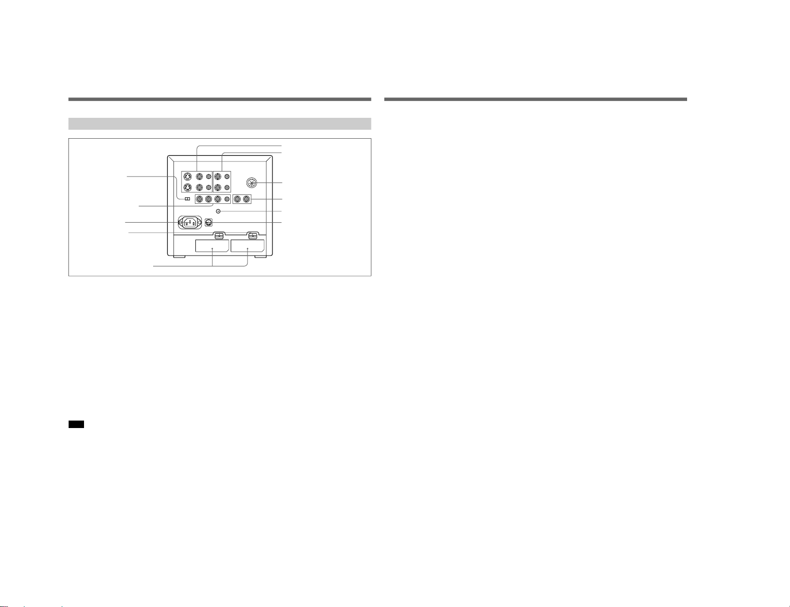
S MIC Chassis
8
(US)
Location and Function of Parts and Controls
!• LINE A connectors
Y/C IN (4-pin mini DIN): Connect to the Y/C
separate output of a video camera, VCR or other
video equipment.
Y/C OUT (4-pin mini DIN): Loop-through output of
the Y/C IN connector. Connect to the Y/C separate
input of a VCR or another monitor.
VIDEO IN (BNC): Connect to the video output of a
video camera, VCR or other video equipment.
VIDEO OUT (BNC): Loop-through output of the
VIDEO IN connector. Connect to the video input
of a VCR or another monitor.
AUDIO IN (phono jack): Connect to the audio
output of a VCR or a microphone (through a
suitable microphone amplifier).
AUDIO OUT (phono jack): Loop-through output of
the AUDIO IN connector. Connect to the audio
input of a VCR or another monitor.
Note
The Y/C IN connector has a priority over the VIDEO
IN connector.
When a plug is connected to the Y/C IN connector, the
VIDEO IN connector is automatically disconnected.
To monitor the signal fed through these connectors,
keep the LINE/RGB selector and the A/B, RGB/Y R-Y
B-Y selector on the front panel released (LINE and A).
!ª LINE B connectors
To monitor the signal fed through these connectors,
keep the LINE/RGB selector released (LINE) and
depress the A/B, RGB/Y R-Y B-Y selector on the front
panel (B).
VIDEO IN (BNC): Connect to the video output of a
video camera, VCR or other video equipment.
VIDEO OUT (BNC): Loop-through output of the
VIDEO IN connector. Connect to the video input
of a VCR or another monitor.
AUDIO IN (phono jack): Connect to the audio
output of a VCR or a microphone (through a
suitable microphone amplifier).
AUDIO OUT (phono jack): Loop-through output of
the AUDIO IN connector. Connect to the audio
input of a VCR or another monitor.
@º REMOTE connector (8-pin mini DIN)
Connect to the tally output of a control console,
special-effect generator, etc. The tally lamp on the
front panel will be turned on and off by the connected
equipment. This connector can be used for connecting
a remote controller.
For the pin assignment of this connector, see
“Specifications” on page 12 (US).
Rear
!• LINE A connectors
!ª LINE B connectors
@º REMOTE connector
(8-pin mini DIN)
@¡ EXT SYNC (external sync)
connectors
@™ V HOLD (vertical hold) control
@£ DC 12V IN jack (XLR, 4 pin)
@¢ COMPONENT
LEVEL selector
@∞ RGB/COMPONENT
input connectors
@§ AC IN socket
@¶ EJECT buttons
@• BATTERY compartments
9
(US)
@¡ EXT SYNC (external sync) connectors
IN (BNC): When this monitor operates on an
external sync signal, connect the reference signal
from a sync generator to this connector. In this
case, depress the SYNC INT/EXT selector on the
front panel (EXT).
OUT (BNC): Loop-through output of the EXT
SYCN IN connector. Connect to the external sync
input of video equipment to be synchronized with
this monitor.
@™ V HOLD (vertical hold) control
Turn to stabilize the picture if it rolls vertically.
@£ DC 12V IN jack (XLR, 4 pin)
Connect the Sony battery adaptor DC-L10 (not
supplied).
@¢ COMPONENT LEVEL selector
Select the component level from among two modes.
N10/SMPTE: for 100/0/100/0 signal
BETA 0: for 100/0/75/0 signal
@∞ RGB/COMPONENT input connectors
R/R-Y, G/Y, B/B-Y (BNC), AUDIO (phono):
To monitor a signal fed through these connectors,
depress the LINE/RGB selector on the front panel
(RGB). When the SYNC INT/EXT selector on the
front paner is released (INT), the monitor operates on
the sync signal from the G/Y channel.
To monitor the analog RGB signal
Connect to the analog RGB signal outputs of a video
camera. Keep the A/B, RGB/Y R-Y B-Y selector on
the front panel released (RGB).
To monitor the component signal
Connect to the R-Y/Y/B-Y componenet signal outputs
of a Sony BetaCam video camera. Depress the A/B,
RGB/Y R-Y B-Y selector on the front panel (Y R-Y BY).
@§ AC IN socket
Connect the supplied AC power cord to this socket and
to a wall outlet.
@¶ EJECT buttons
Press the EJECT button upwards to remove the battery
pack.
@• BATTERY compartments
Insert the NP-1B battery pack (not supplied).
1-19
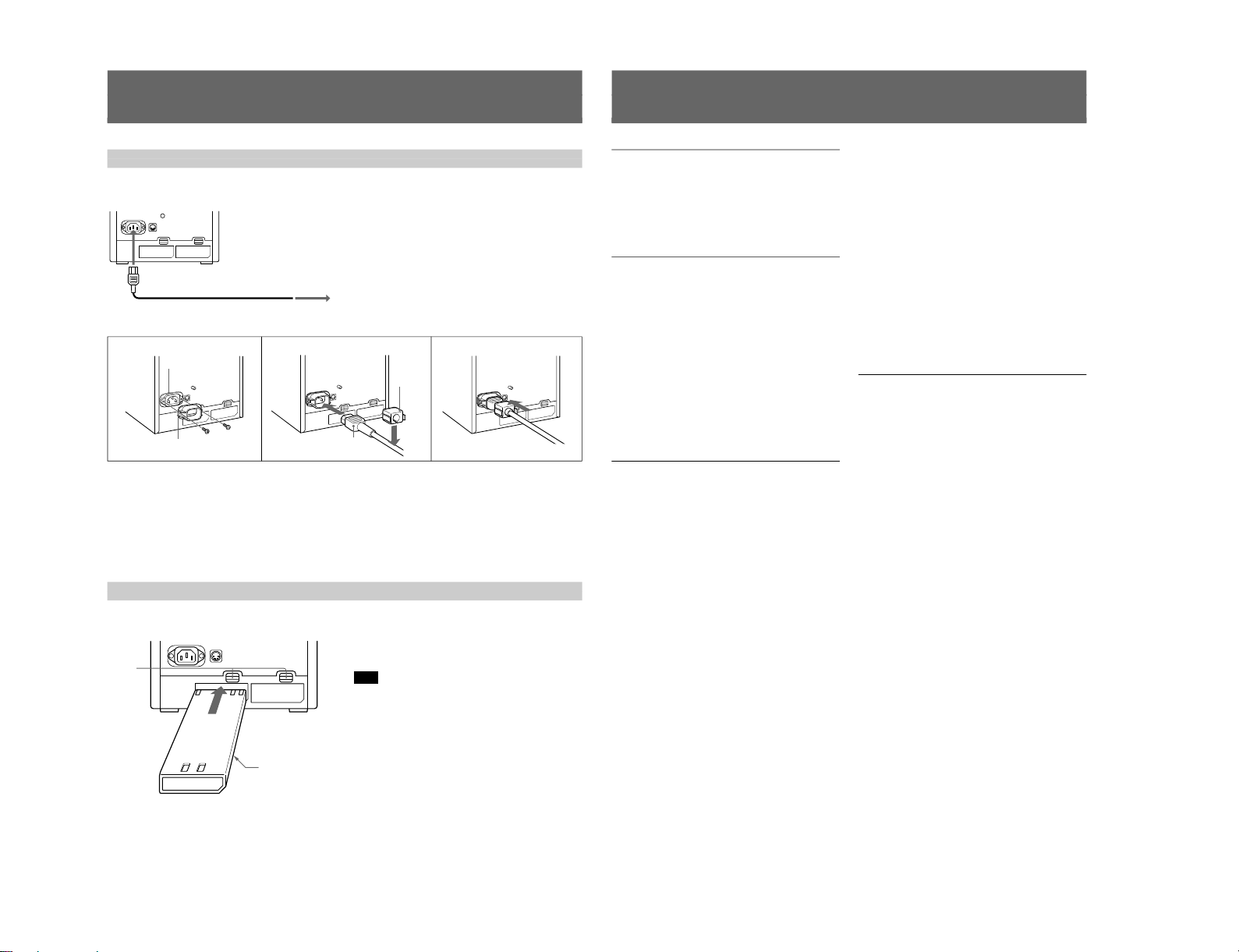
1-20
10
(US)
Power Sources
Connect the supplied AC power cord to the AC IN
socket and to a wall outlet.
1
Remove the AC IN socket screws and then use
them to attach the AC plug holder A (supplied) to
the AC IN socket.
2
Plug the power cord to the AC IN sokcet. Then,
attach the supplied AC plug holder B on top of the
AC power cord.
The monitor can operate with one or two battery packs.
For extended use, two battery packs are recommended.
House Current (for all models)
to AC IN
to a wall outlet
When the AC power cord is plugged into the AC IN
socket, the battery pack (if installed) or the AC power
adaptor (if connected) is automatically disconnected.
To connect an AC power cord securely with AC plug holders.
3
21
AC IN socket
AC plug holder A
AC power plug
AC plug
holder B
3
Slide AC plug holder B over the cord until is locks.
To remove the AC power cord
Pull out AC plug holder B by squeezing the left and
right sides.
Rechargeable Battery
To remove the battery pack, press the EJECT button
upwards.
For charging, use the BC-1WD for the NP-1B.
Note
Make sure you disconnect the cables connected to the
connectors (AC IN, DC 12 V IN) at the rear of the
monitor. Otherwise, the monitor cannot operate on the
battery pack(s).
SONY mark downwards
EJECT
buttons
NP-1B
(not supplied)
11
(US)
Specifications
Video signal
Color system PAL-M, NTSC
Resolution 450 TV lines
Aperture correction –4.0 dB to +6.0 dB (at 3.0 MHz)
Frequency response 6.0 MHz (–3 dB) at all inputs
Synchronization AFC time constant 1.0 msec.
Picture performance
Normal scan 6% over scan of CRT effective
screen area
Underscan 3% underscan of CRT effective
screen area
H. linearity Less than 5.0% (typical)
V. linearity Less than 5.0% (typical)
Convergence Central area: 0.43 mm (typical)
Peripheral area: 0.53 mm
(typical)
Raster size stability H: 1.0%, V: 1.5%
High voltage regulation
3.0%
Color temperature D65
Inputs and Outputs
Inputs Y/C IN: 4-pin mini DIN
connector
See the pin assignment on page
12 (US).
VIDEO IN: BNC connector
1 Vp-p ± 6 dB, sync negative
AUDIO IN: phono jack, –5 dBu
a)
,
less than 47 kohms
R/R-Y, G/Y, B/B-Y: BNC
connector
R, G, B channels: 0.7 Vp-p,
± 6 dB Sync on green: 0.3 Vp-p,
negative,
R-Y, Y, B-Y channels: 0.7 Vp-p,
±6 dB (Standard colour bar
signal of 75% chrominance)
EXT SYNC IN: BNC connector
Composite sync 4 Vp-p, ±6 dB,
negative
Loop-through outputs
Y/C OUT: 4-pin mini DIN
connector, 75 ohms terminated
(75 ohms automatic termination)
VIDEO OUT: BNC connector,
75 ohms terminated (75 ohms
automatic termination)
AUDIO OUT: phono jack
EXT SYNC OUT: BNC
connector, 75 ohms terminated
Speaker output Output level 0.5 W
Remote input REMOTE: 8-pin mini DIN
connctor (75 ohms automatic
termination)
See the pin assignment on page
12 (US).
a) 0 dBu = 0.775 Vr.m.s.
General
Power consumption & requirements
0.6 A 45 W MAX at 120 V AC
operation
3.7 A 38 W at 12 V DC operation
Operating conditions
Temperature 0 to +35°C (32 to 95°F)
Humidity 0 to 90% (no condensation)
Pressure 700 to 1060 hPa
Transport and storage conditions
Temperature –10 to +40°C (14 to 104°F)
Humidity 0 to 90%
Pressure 700 to 1060 hPa
Dimensions Approx. 217 x 217 x 352.5 mm
(w/h/d) (8
5
/8 × 8
5
/8 × 14 inches)
not incl. projecting parts and
controls
Mass Approx. 8.2 kg (18 lb 1 oz) not
incl. battery packs
Accessory supplied AC power cord (1)
Cable with an 8-pin connector (1)
AC plug holders (1 set)
Tally plate (1)
Design and specifications are subject to change
without notice.
S MIC Chassis
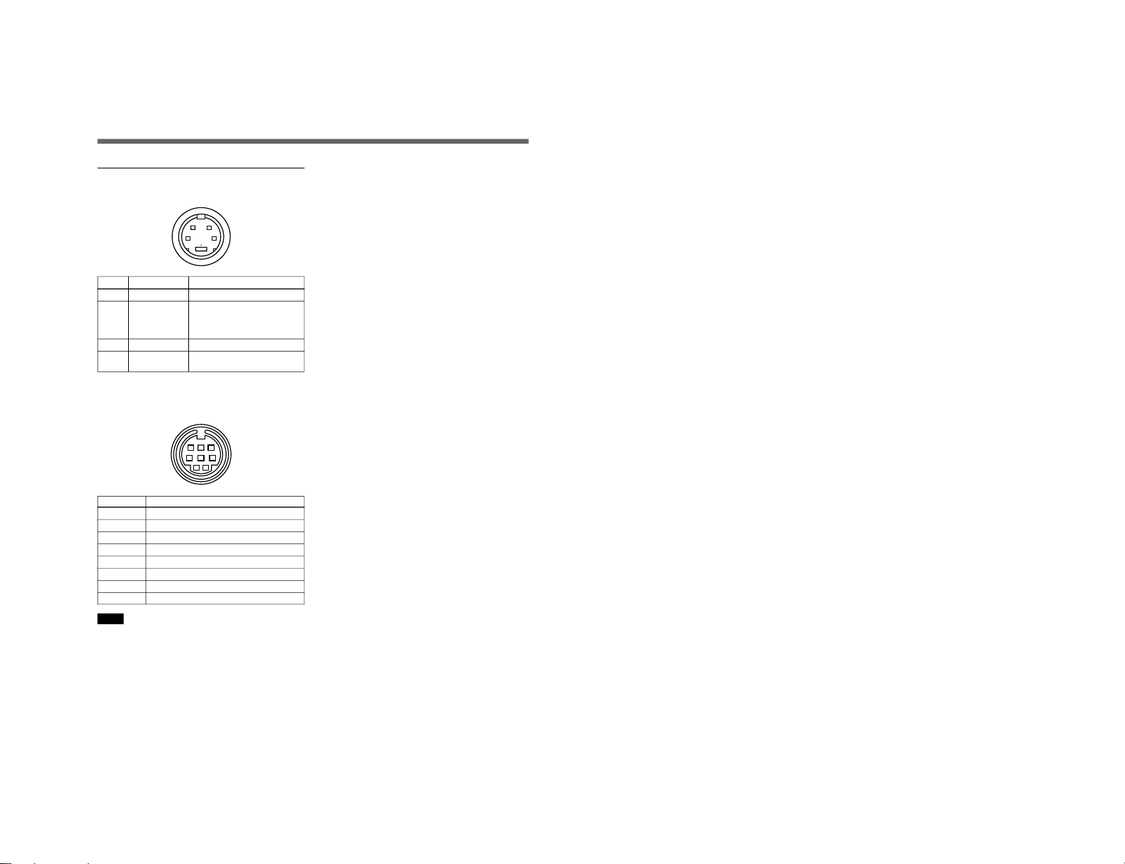
S MIC Chassis
12
(US)
Pin Assignment
Y/C IN connector (4-pin mini DIN)
12
43
Pin No. Signal Description
1 Y-input 1 Vp-p, sync negative, 75 ohms
2 CHROMA 300 mVp-p (PAL-M),
286 mVp-p (NTSC), burst
sub-carrier-input Delay time between Y and
C: within 0 ±100 nsec., 75 ohms
3 GND for Y-input GND
4 GND for
GND
CHROMA-input
REMOTE connector (8-pin mini DIN)
(PVM-8045Q/8042Q only)
12
3
678
45
Pin No. Signal
1 16:9
2 H/V delay
3 GND
4 EXT SYNC
5 Tally
6 Underscan
7 A/B or RGB/Y R-Y B-Y
8 LINE/RGB
Notes
•For remote control, connect the pin of the desired
function to pin 3 (GND).
•For remote control, set the front button to OFF (the
switch is out).
Specifications
1-21

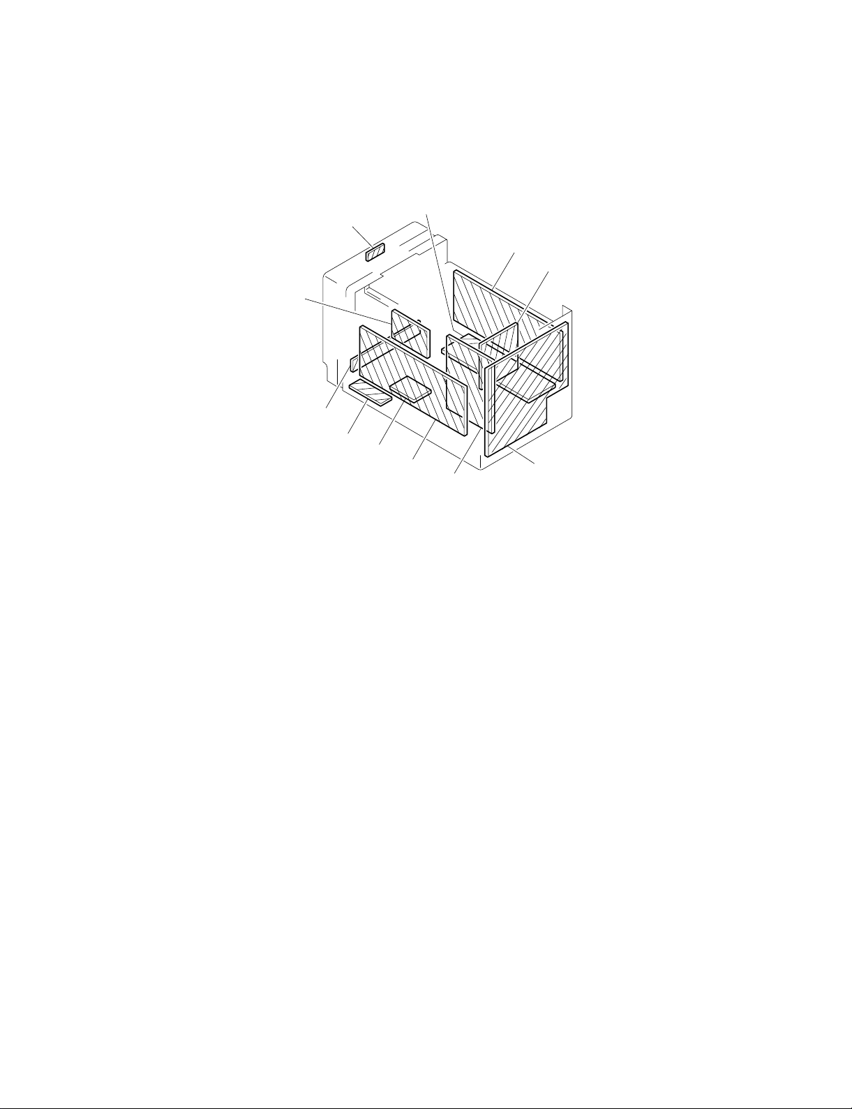
SERVICE INFORMATION
2-1. CIRCUIT BOARDS LOCATION
SECTION 2
PA board
HA board
A
board
F
X board
S board
P board
B board
G board
D board
Q
A
A
board
C
board
S MIC Chassis
2-1
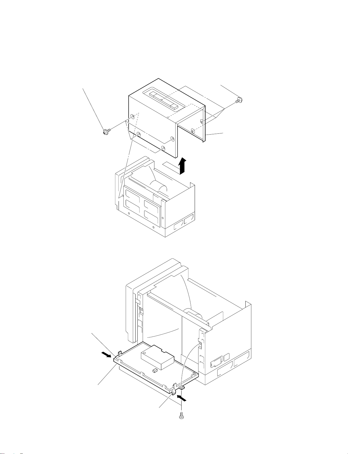
2-2. DISASSEMBLY
2-2-1. Cabinet Removal
Remove the four case fixing
1
screws (4 x 6).
Remove the four case fixing
2
screws (4 x 6).
3 Remove the cabinet.
2-2-2. B Board Removal
3 Unhook the claw.
4 Open the B board.
2 Unhook the claw.
2-2
1 Remove the two screws (BVTP3 x 8).
S MIC Chassis
 Loading...