

Page 1

3-798-310- 24 (1)
Trinitron Color Video Monitor
Model:
PVM-1353MD
PVM-1953MD
Operating Instructions page 2
Before operating the unit, please read this manual thoroughly
and retain it for future reference.
Mode d’emploi page 15
Avant la mise en service de cet appareil, prière de lire
attentivement ce mode d’emploi et de le conserver pour toute
référence ultérieure.
Manual de instrucciones
Antes de utilizar la unidad, lea este manual detenidamente y
consérvelo para futuras referencias.
página 29
Owner’s Record
The model and serial numbers are located at the rear.
Record the model and serial numbers in the spaces provided
below. Refer to these numbers whenever you call upon your
Sony dealer regarding this product.
Model No. Serial No.
1995 by Sony Corporation
Page 2
English
WARNING
To prevent fire or shock hazard, do not
expose the unit to rain or moisture.
Dangerously high voltages are present inside the unit. Do
not open the cabinet. Refer servicing to qualified personnel
only.
In the event of a malfunction or when maintenance is
necessary, consult an authorized Sony dealer.
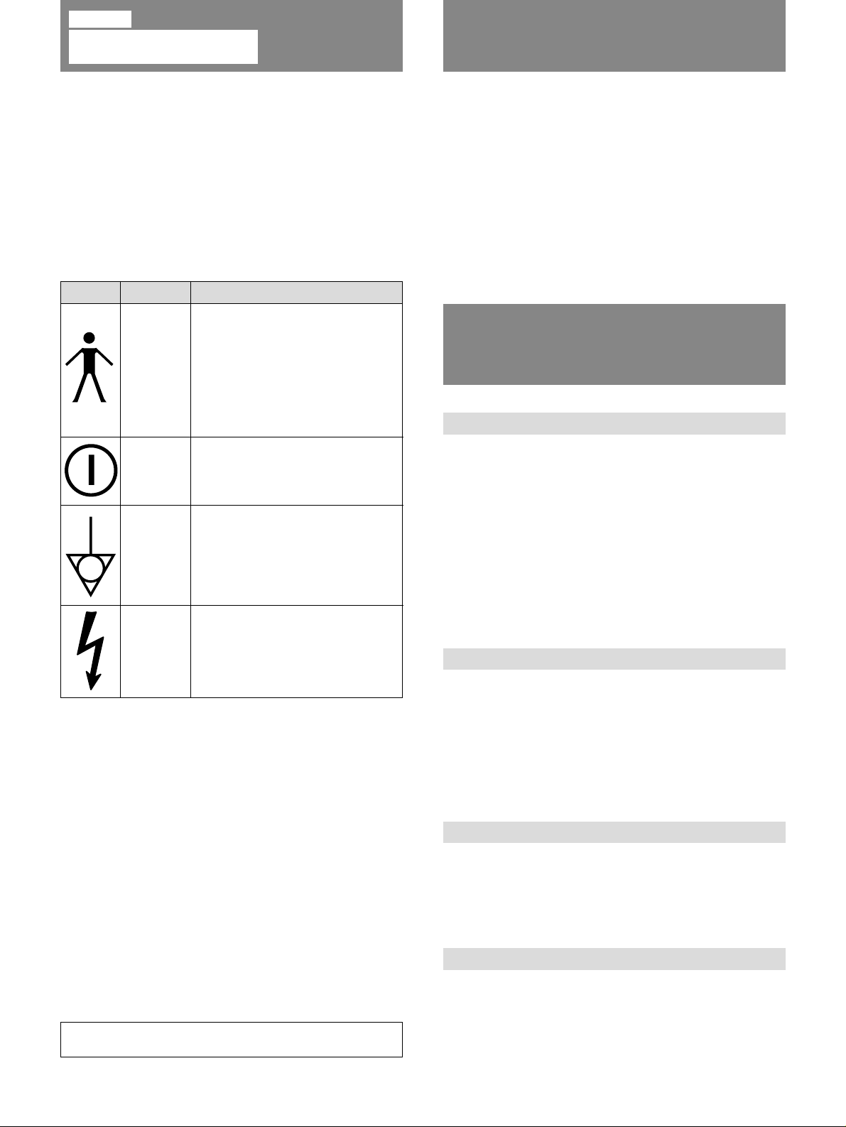
Symbols on the unit
Symbol This symbol indicates
Type B
For the Customers in the USA
This equipment has been tested and found to comply with
the limits for a Class A digital device, pursuant to Part 15 of
the FCC Rules. These limits are designed to provide
reasonable protection against harmful interference when the
equipment is operated in a commercial environment. This
equipment generates, uses, and can radiate radio frequency
energy and, if not installed and used in accordance with the
instruction manual, may cause harmful interference to radio
communications. Operation of this equipment in a residential area is likely to cause harmful interference in which case
the user will be required to correct the interference at his
own expense.
You are cautioned that any changes or modifications not
expressly approved in this manual could void your authority
to operate this equipment.
For the Customers in Canada
This Class A digital apparatus meets all requirements of the
Canadian Interference-Causing Equipment Regulations.
Be sure to connect the AC power cord to a grounded
outlet.
2
Location
Rear
panel
Front
panel
Rear
panel
Inside the
unit
Type B equipment classified in
accordance with IEC Publication
601-1 Safety of medical electrical
equipment.
Type B equipment is, for example,
suitable for external and internal
application to the patient, excluding
direct cardiac application.
Main power switch.
Press to turn the monitor on or off.
The equipotential terminal which
brings the various parts of a
system to the same potential.
Presence of uninsulated
“dangerous voltage” within the
product’s enclosure that may be
sufficient to constitute a risk of
electric shock.
Tab le of Contents
Precautions ......................................................................... 2
Features............................................................................... 3
Location and Function of Parts and Controls ..................... 4
Front Panel........................................................................ 4
Rear Panel......................................................................... 6
Using On-Screen Menus..................................................... 8
Power Sources .................................................................. 11
Attaching the Splash Proof Covers................................... 12
Attaching the Control Panel Cover................................... 12
Specifications ................................................................... 13
Precautions
On safety
• Operate the unit on 120 V AC only.
• The nameplate indicating operating voltage, power
consumption, etc. is located on the rear.
• Should any solid object or liquid fall into the cabinet,
unplug the unit and have it checked by qualified
personnel before operating it any further.
• Unplug the unit from the wall outlet if it is not to be used
for several days or more.
• To disconnect the AC power cord, pull it out by grasping
the plug. Never pull the cord itself.
• The socket-outlet shall be installed near the equipment
and shall be easily accessible.
On installation
• Allow adequate air circulation to prevent internal heat
build-up.
Do not place the unit on surfaces (rugs, blankets, etc.) or
near materials (curtains, draperies) that may block the
ventilation holes.
• Do not install the unit in a location near heat sources such
as radiators or air ducts, or in a place subject to direct
sunlight, excessive dust, mechanical vibration or shock.
On cleaning
To keep the unit looking brand-new, periodically clean it
with a mild detergent solution. Never use strong solvents
such as thinner or benzine, or abrasive cleansers since they
will damage the cabinet. As a safety precaution, unplug the
unit before cleaning it.
On repacking
Do not throw away the carton and packing materials. They
make an ideal container which to transport the unit. When
shipping the unit to another location, repack it as illustrated
on the carton.
If you have any questions about this unit, contact your
authorized Sony dealer.
Page 3
Features
Picture
HR (High Resolution) Trinitron picture tube
HR Trinitron tube provides a high resolution picture.
Horizontal resolution is more than 600 TV lines at the
center of the picture.
Comb filter
When NTSC video signals are received, a comb filter
activates to increase the resolution, resulting in fine picture
detail without color spill or color noise.
Beam current feedback circuit
The built-in beam current feedback circuit assures stable
white balance.
Inputs
Two color systems available
The monitor can display PAL, and NTSC signals. The
appropriate color system is selected automatically.
Analog RGB/component input connectors
Analog RGB or component (Y, R-Y and B-Y) signals from
video equipment can be input through these connectors.
Press the RGB/COMPONENT A/B select button on the
front panel and select RGB or component signals from the
on-screen menu.
Y/C input connector (S input connector)
The video signal, split into the chrominance signal (C) and
the luminance signal (Y), can be input through this
connector, eliminating the interference between the two
signals, which tends to occur in a composite video signal,
assuring video quality.
External sync input connectors
When the external RGB or component signal is input and
sync signal is set to external in the on-screen menu, the
monitor can be operated on the sync signal supplied from
an external sync generator.
Functions
On-screen menus
You can set color temperature, CHROMA SET UP, and
other settings by using the on-screen menus.
Overscan mode
The display size is enlarged by approximately 20% and the
center part of the screen is easier to watch.
Underscan mode
The signal normally scanned outside of the screen can be
monitored in the underscan mode.
Note
When the monitor is in the underscan mode, the dark RGB
scanning lines may appear on the top edge of the screen.
These are caused by an internal test signal, rather than the
input signal.
Split function
The display splits into two parts (upper and lower). The
upper part of the screen monitors the signal fed through the
RGB/COMPONENT A input connectors and lower part of
the screen monitors the signal fed through the RGB/
COMPONENT B input connectors. You can compare the
two screens.
Caption vision (Closed Caption) decoder
When a signal with Caption Vision is input, the caption is
superimposed on the screen. You can select ON or OFF and
set the caption type on the on-screen menu.
Auto/manual degaussing
Degaussing of the screen can be performed automatically
when the power is turned on, or manually by pressing the
DEGAUSS button.
Five menu languages
You can select the language used for on-screen menus from
the five languages.
English
Automatic termination
(only terminals with the mark)
The BNC input connectors on the rear panel are terminated
at 75 ohms inside, when no cable is connected to the loopthrough output connectors. When a cable is connected to an
output connector, the 75-ohm termination is automatically
released.
Splash proof cover(s) and control panel cover
Splash proof covers that protect the ventilation holes from
splashes (of medicines, etc.) and a control panel cover that
protects the control buttons on the front panel from
undesired touching are supplied.
Quick Reference Card
The Quick Reference Card is supplied to help you
understand the menu configuration and operating method.
You can attach the supplied double-sided adhesive tapes on
the rear of the card.
EIA standard 19-inch rack mounting
By using an MB-502B (for PVM-1353MD) or SLR-103
(for PVM-1953MD) Mounting Bracket (not supplied), the
monitor can be mounted in an EIA standard 19-inch rack.
For details on mounting, see the instruction manual of the
mounting bracket kit.
3
Page 4
Location and Function of P arts and Controls
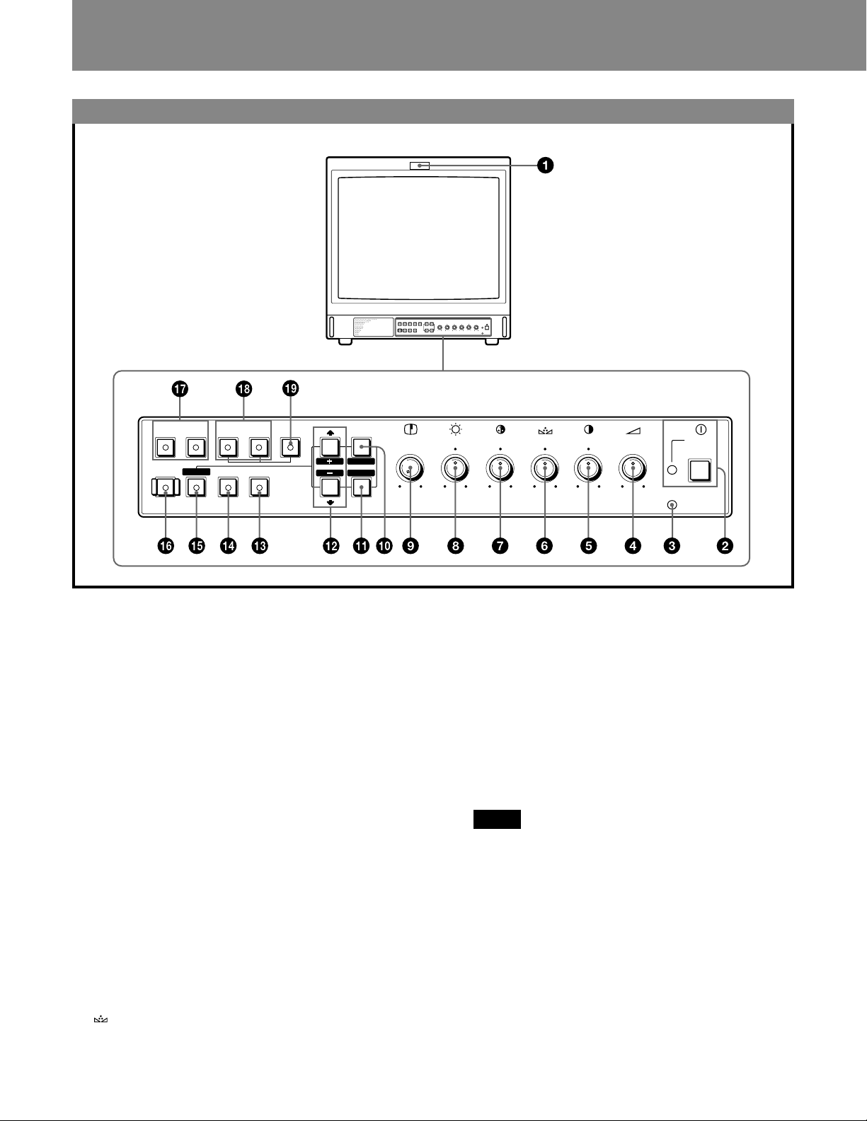
Front Panel
RESET
RGB/COMPONENT
A
B
UNDER
OVER
SCAN
SCAN
SPLIT
MENU
EXIT
SELECT
ENTER
LINE
AB
DEGAUSS
1 Tally indicator
This indicator lights up when the video camera
connected to this monitor is selected, indicating that the
picture is being recorded. The tally control connection is
needed.
For the pin assignment, see “Specifications” on page 14.
2 U POWER switch and indicator
Depress to turn the monitor on. The indicator will light
up in green. To turn the power off, press this again.
3 REMOTE indicator
This indicator lights up in the conditions below:
— When PRESET is set to ON in the menu.
— When REMOTE (RS-232C) is set to REMOTE
ONLY or REMOTE & LOCAL in the menu, or
— When REMOTE ON is set via the REMOTE 1
terminal.
4 ¸ VOLUME control
Turn this control clockwise or counterclockwise to
obtain the desired volume.
5 > CONTRAST control
Turn clockwise to make the contrast stronger and
counterclockwise to make it weaker.
6 PHASE control
This control is effective only for the NTSC color
system. Turn clockwise to make the skin tones greenish
and counterclockwise to make them purplish.
4
APERTURE
MIN
MAX
POWER
REMOTE
–+
MIN
CONTRAST
PHASECHROMABRIGHT
MAX
PUR GRN MIN MAX MIN MAX
VOLUME
7 ¯ CHROMA (chrominance) control
Turn clockwise to make the color intensity stronger and
counterclockwise to make it weaker.
8 ¨ BRIGHT (brightness) control
Turn clockwise for more brightness and
counterclockwise for less.
9 ΠAPERTURE control
Turn clockwise for more sharpness and
counterclockwise for less.
When the control is set to MIN, the picture becomes flat
without need for corrections.
Note
The APERTURE, CHROMA, PHASE control settings
have no effect on the pictures of RGB signals.
!º MENU (EXIT) button
Press to make the menu appear.
Press to return to the previous screen in the menu.
!¡ ENTER (SELECT) button
Press to decide a selected item in the menu.
!™ > (+)/ . (–) buttons
Press to move the cursor (z) or adjust selected value in
the menus.
Page 5

!£ OVERSCAN button
Press (light on) for overscanning. The display size is
extended by approximately 20% so that the center of
screen is easier to watch. By pressing the button again,
the display returns to the normal size (light off).
!¢ UNDERSCAN button
Press (light on) for underscanning. The display size is
reduced by approximately 5% so that four corners of the
raster are visible. By pressing the button again, the
display returns to the normal size (light off).
!∞ RESET button
During menu adjustments, press to reset the setting in
the menu.
!§ DEGAUSS button
Press this button momentarily. The screen will be
demagnetized.
Wait for 10 minutes or more before activating this
button again.
Note
The picture rolls vertically while the screen is being
demagnetized.
c
English
!¶ LINE A/B select buttons
Press to select a signal (light on).
A:Press to monitor the signal fed through the LINE A
input connectors.
B: Press to monitor the signal fed through the LINE B
input connectors.
!• RGB/COMPONENT A/B select buttons
Press to select a signal (light on).
A:Press to monitor the signal fed through the RGB/
COMPONENT A input connectors.
B: Press to monitor the signal fed through the RGB/
COMPONENT B input connectors.
!ª SPLIT button
When you select RGB signals fed through the RGB/
COMPONENT A and RGB/COMPONENT B input
connectors, press this button (light on) to split the
display into two parts (upper and lower), and monitor
the both RGB signals simultaneously.
Note
Make sure the signals fed through the RGB/
COMPONENT A and RGB/COMPONENT B input
connectors are synchronized.
5
Page 6
Location and Function of Parts and Controls
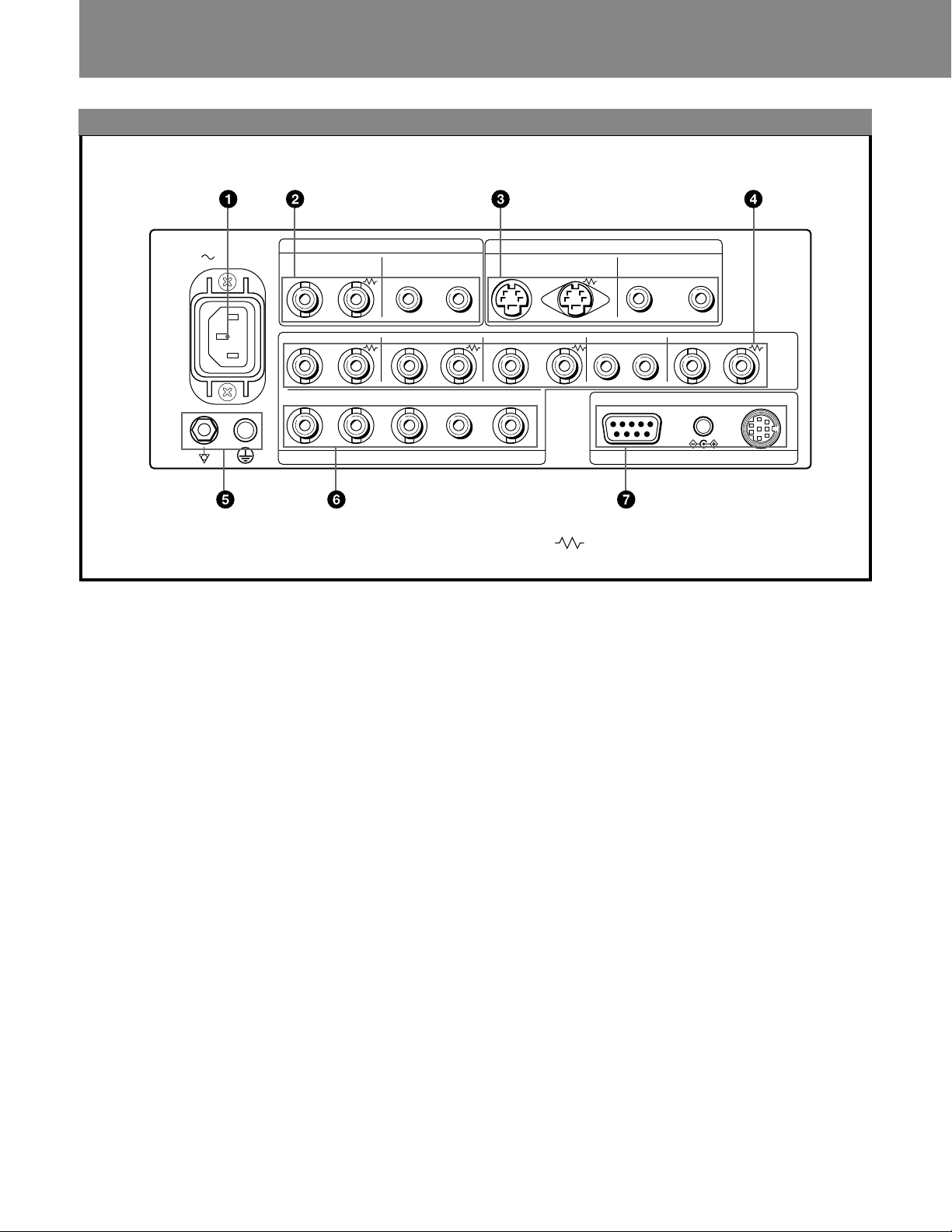
Rear Panel
AC IN
VIDEO AUDIO
R/R–Y G/Y B/B–Y
A
IN
R/R–Y
B
IN
LINE A
OUT IN OUT IN OUT IN OUT IN OUT
G/Y B/B–Y
IN IN
RGB/COMPONENT
1 AC IN socket
Connect the supplied AC power cord to this socket.
2 LINE A connectors
Line input connectors for the composite video and audio
signals and their loop-through output connectors.
To monitor the input signal fed through these
connectors, press LINE A select button (light on) on the
front panel.
VIDEO IN (BNC)
Connect to the video output connector of a video
equipment, such as a VTR or a color video camera. For
a loop-through connection, connect to the video output
connector of another monitor.
VIDEO OUT (BNC)
Loop-through output of the VIDEO IN connector.
Connect to the video input connector for a VTR or
another monitor.
When the cable is connected to this connector, the
75-ohms termination of the input is automatically
released, and the signal input to the VIDEO IN
connector is output from this connector.
AUDIO IN (phono jack)
Connect to the audio output connector of a VTR or to a
microphone through a suitable microphone amplifier.
For a loop-through connection, connect to the audio
output connector of another monitor.
AUDIO OUT (phono jack)
Loop-through output of the AUDIO IN connector.
Connect to the audio input connector of a VTR or
another monitor.
IN OUTIN OUT
EXT SYNC
AUDIO
IN IN
Y/C
IN OUT
(The mark indicates automatic termination.)
LINE B
AUDIO
AUDIO
IN OUT
RS-232C
EXT SYNC
5V/1A
REMOTE
REMOTE 1DC OUT
3 LINE B connectors
Separated Y/C input connectors, audio input
connectors, and corresponding loop-through output
connectors.
To monitor the input signal fed through these
connectors, press LINE B select button (light on) on the
front panel.
Y/C IN (4-pin mini DIN)
Connect to the Y/C separate output connector of a VTR,
video camera or other video equipment.
Y/C OUT (4-pin mini DIN)
Loop-through output of the Y/C IN connector. Connect
to the Y/C separate input connector of a VTR or another
monitor.
When the cable is connected to this connector, the
75-ohms termination of the input is automatically
released, and the signal input to the Y/C IN connector is
output from this connector.
AUDIO IN (phono jack)
Connect to the audio output connector of a VTR or to a
microphone through a suitable microphone amplifier.
For a loop-through connection, connect to the audio
output connector of another monitor.
AUDIO OUT (phono jack)
Loop-through output of the AUDIO IN connector.
Connect to the audio input connector of a VTR or
another monitor.
6
Page 7

4 RGB/COMPONENT A connectors
RGB signal or component signal input connectors and
their loop-through output connectors.
To monitor the input signal fed through these
connectors, press the RGB/COMPONENT A select
button (light on) on the front panel.
Then select one out of four items in the RGB A
SYSTEM menu to set the RGB or COMP (component)
signal and the INT SYNC (internal sync) or EXT SYNC
(external sync) signal.
For the operation through the menus, see pages 8 to 10.
R/R-Y IN, G/Y IN, B/B-Y IN (BNC)
When “RGB-INT SYNC” or “COMP-INT SYNC” is
selected in the RGB A SYSTEM menu, the monitor
operates on the sync signal from the G/Y channel.
To monitor the RGB signal
Connect to the analog RGB signal output connectors of
a video camera.
To monitor the component signal
Connect to the R-Y/Y/B-Y component signal output
connectors of a Sony Betacam SPTM camcorder.
R/R-Y OUT, G/Y OUT, B/B-Y OUT (BNC)
Loop-through outputs of the R/R-Y IN, G/Y IN, B/B-Y
IN connectors.
When the cables are connected to these connectors, the
75-ohms termination of the inputs is automatically
released, and the signal inputs to the R/R-Y IN, G/Y IN,
B/B-Y IN connectors are output from these connectors.
To output the analog RGB signal
Connect to the analog RGB signal input connectors of a
video printer or another monitor.
To output the component signal
Connect to the R-Y/Y/B-Y component signal input
connectors of a Sony Betacam SP VTR.
AUDIO IN (phono jack)
Connect to the audio output connector of video
equipment when the analog RGB or component signal is
input.
AUDIO OUT (phono jack)
Loop-through outputs of the AUDIO IN connector.
EXT SYNC (external sync) IN (BNC)
When this monitor operates on an external sync signal,
connect the signal from a sync generator to this
connector.
To use the sync signal fed through this connector, select
“RGB-EXT SYNC” or “COMP-EXT SYNC” in the
RGB A SYSTEM menu.
EXT SYNC (external sync) OUT (BNC)
Loop-through output of the EXT SYNC IN connector.
Connect to the external sync input connector of video
equipment to be synchronized with this monitor.
When the cable is connected to this connector, the
75-ohms termination of the input is released, and the
signal input to the EXT SYNC IN connector is output
from this connector.
5 Ground (1/<) terminal
Connect a GND cable.
6 RGB/COMPONENT B connectors
RGB signal or component signal input connectors.
To monitor the input signal fed through these
connectors, press the RGB/COMPONENT B select
button (light on) on the front panel.
Then select one out of four items in the RGB B
SYSTEM menu to set the RGB or COMP (component)
signal and the INT SYNC (internal sync) or EXT SYNC
(external sync) signal.
For the operation through the menus, see pages 8 to 10.
R/R-Y IN, G/Y IN, B/B-Y IN (BNC)
When “RGB-INT SYNC” or “COMP-INT SYNC” is
selected in the RGB B SYSTEM menu, the monitor
operates on the sync signal from the G/Y channel.
To monitor the RGB signal
Connect to the analog RGB signal output connectors of
a video camera.
To monitor the component signal
Connect to the R-Y/Y/B-Y component signal output
connectors of a Sony Betacam SP camcorder.
AUDIO IN (phono jack)
Connect to the audio output connector of video
equipment when the analog RGB or component signal is
input.
EXT SYNC (external sync) IN (BNC)
When this monitor operates on an external sync signal,
connect the signal from a sync generator to this
connector.
To use the sync signal fed through this connector, select
“RGB -EXT SYNC” or “COMP-EXT SYNC” in the
RGB B SYSTEM menu.
7 REMOTE connectors
RS-232C (D-sub 9-pin)
Connect to the RS-232C control connector of other
equipment. You can operate the monitor with the
control command from the equipment.
For the details, see the supplied Interface Manual for
Programmers.
REMOTE 1 (8-pin mini DIN)
Connect to the tally output connector of a control
console, effects, etc. The tally indicator on the front
panel will be turned on and off by the connected
equipment.
You can also connect a remote controller using this
connector.
For the pin assignments of these connectors, see
“Specifications” on page 14.
DC OUT 5V/1A connector
You can use this connector as a power source for the
other equipment.
DC 5V/1A is output.
English
7
Page 8
Using On-Screen Menus
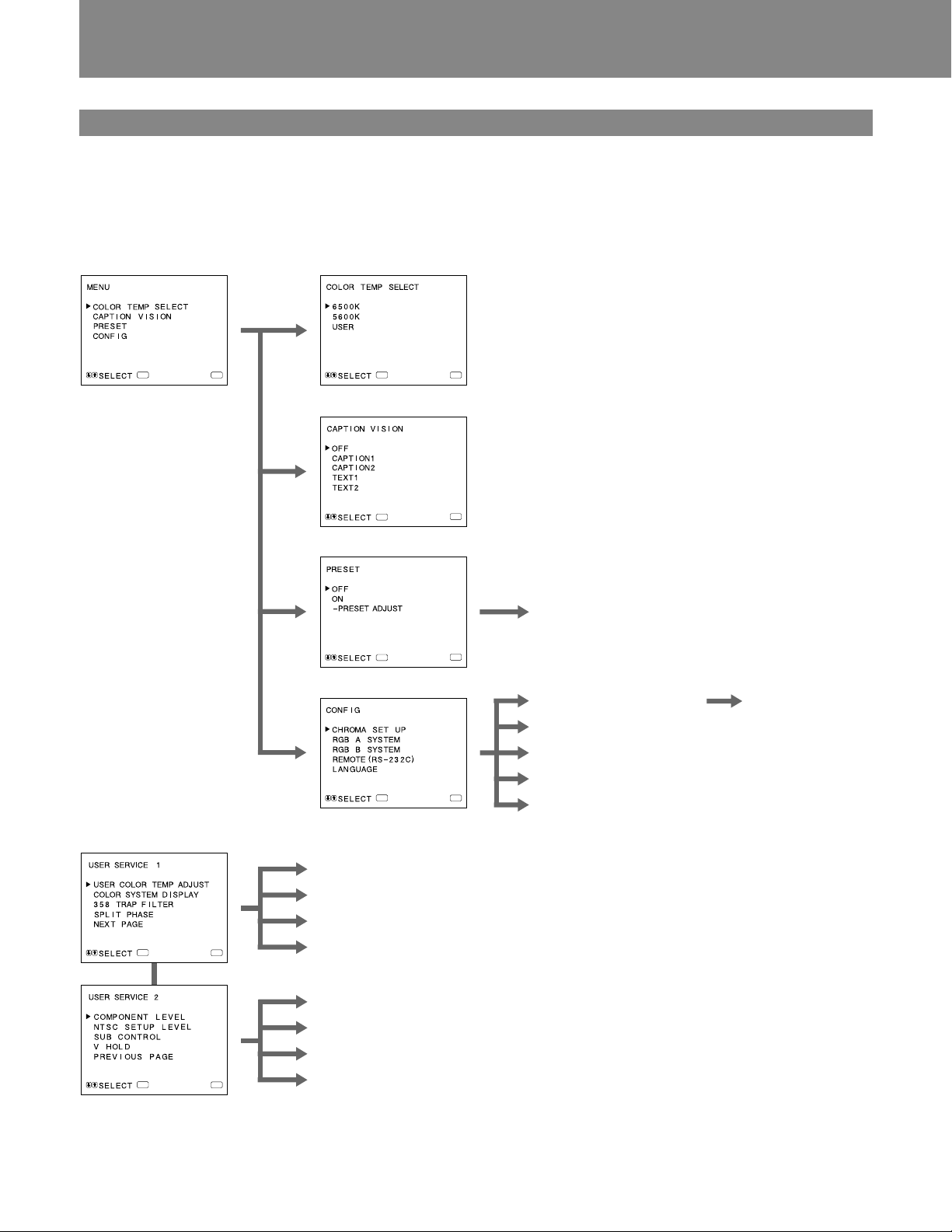
Menu Configuration
The flow chart shows the different levels of on-screen
menus that you can use to make various adjustments and
settings.
For details of each menu, see pages 9 and 10.
1 Main menu
ENTER
2 COLOR TEMP SELECT menu
MENU
ENTER
MENU
3 CAPTION VISION menu
ENTER
MENU
4 PRESET menu
6 PRESET ADJUST screen
ENTER
MENU
5 CONFIG menu
7 CHROMA SET UP menu
!™ AUTO ADJUST
screen
8 RGB A SYSTEM menu
9 RGB B SYSTEM menu
!º REMOTE (RS-232C) menu
ENTER
MENU
!¡ LANGUAGE menu
User Service Mode
ENTER
ENTER
8
!£ USER COLOR TEMP ADJUST menu
!¢ COLOR SYSTEM DISPLAY menu
!∞ 358 TRAP FILTER menu
MENU
!§ SPLIT PHASE menu
!¶ COMPONENT LEVEL menu
!• NTSC SETUP LEVEL menu
!ª SUB CONTROL screen
MENU
@º V HOLD screen
Page 9
c
P
M
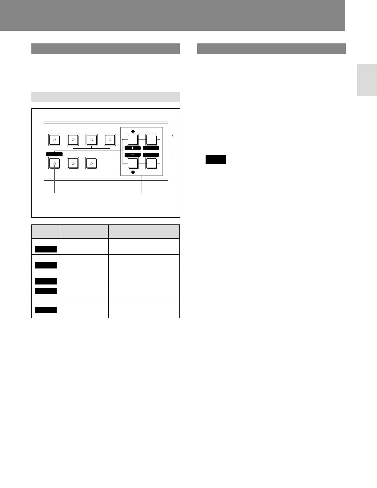
Operating through Menus
There are five buttons for menu operations on the front
panel of the monitor. To display the main menu, first press
MENU (EXIT). The buttons you can use appear at the
bottom of the menu screen.
Functions of the buttons
RGB/COMPONENT
RESET
BLUE
ONLY
RESET
button
ABB SPLIT
UNDER
SCAN
OVER
SCAN
MENU
EXIT
SELECT
ENTER
Buttons for
menu
operations
A
The Contents of Menu Items
The following sentences show the details of each menu
items.
[ ] indicates the factory setting position.
1 Main menu
Select an item and press the ENTER (SELECT) button
to go to the following menu.
2 COLOR TEMP SELECT menu
Select the color temperature from among 6500K, 5600K
and USER. USER is set to 6500K in the factory setting.
You can adjust or change the color temperature in
USER mode (a measuring instrument is needed).
[6500K]
Note
The color temperature of the USER mode can be
adjusted in the range from 3200K to 10000K.
You can adjust the color temperature of the USER mode
in the USER COLOR TEMP ADJUST menu (!£) of
the user service mode.
For the details, see “USER COLOR TEMP ADJUST
menu (!£)” on page 10.
English
Button
MENU
EXIT
ENTER
SELECT
>
+
–
.
RESET
To select menu
item
return to the
previous menu.
decide a
selected item.
move the cursor
(z) upwards.
move the cursor
(z) downwards.
To adjust selected menu
item
return to the previous
menu.
select an item.
increase selected value.
decrease selected value.
reset current adjustment
value to the factory setting.
(The above items in white type correspond to the marks in
the menu.)
3 CAPTION VISION menu
To display closed captions, select ON and the type of
caption you would like.
[OFF]
4 PRESET menu
You can preset each control to a desired level and set it.
If you set PRESET to ON, the REMOTE indicator
lights up and the controls on the front panel do not
work. The monitor operates with the internal memory
settings. For adjustment, select the PRESET ADJUST
screen.
[OFF]
5 CONFIG menu
Select an item for adjustment of the monitor.
6 PRESET ADJUST screen
Adjust CONTRAST, BRIGHT, CHROMA, PHASE,
VOLUME, APERTURE in the PRESET menu.
7 CHROMA SET UP menu
Set to ON to adjust the internal decoder for CHROMA
and PHASE (NTSC signal only) after AUTO ADJUST
screen (!™).
[OFF]
8 RGB A SYSTEM menu
To monitor the signal fed through the RGB/
COMPONENT A connectors, set the RGB or COMP
(component) signal and the INT SYNC (internal sync)
or EXT SYNC (external sync) signal in this menu.
[RGB-EXT SYNC]
9
Page 10
Using On-Screen Menus
9 RGB B SYSTEM menu
To monitor the signal fed through the RGB/
COMPONENT B connectors, set the RGB or COMP
(component) signal and the INT SYNC (internal sync)
or EXT SYNC (external sync) signal in this menu.
[RGB-EXT SYNC]
!º REMOTE (RS-232C) menu
Select one out of following three modes.
REMOTE OFF:
You can adjust settings and controls by the buttons and
controls on the front panel.
RS-232C connector does not function.
REMOTE ONLY:
You can adjust settings and controls through the
RS-232C connector.
Buttons and controls on the front panel, except the
menu operation ones, do not function.
REMOTE & LOCAL:
You can adjust settings and controls both through the
RS-232C connector and the front panel buttons.
Controls on the front panel do not function.
[REMOTE OFF]
!¡ LANGUAGE menu
You can select the language used for on-screen menus
from the following five languages (English, German,
French, Italian, Spanish).
[ENGLISH]
!™ AUTO ADJUST screen
Select the color bar signal (full, SMPTE, EIA) and press
the ENTER (SELECT) button to start automatic
adjustment for CHROMA and PHASE. For these
adjustments to be valid, you must select ON in
CHROMA SET UP menu (7).
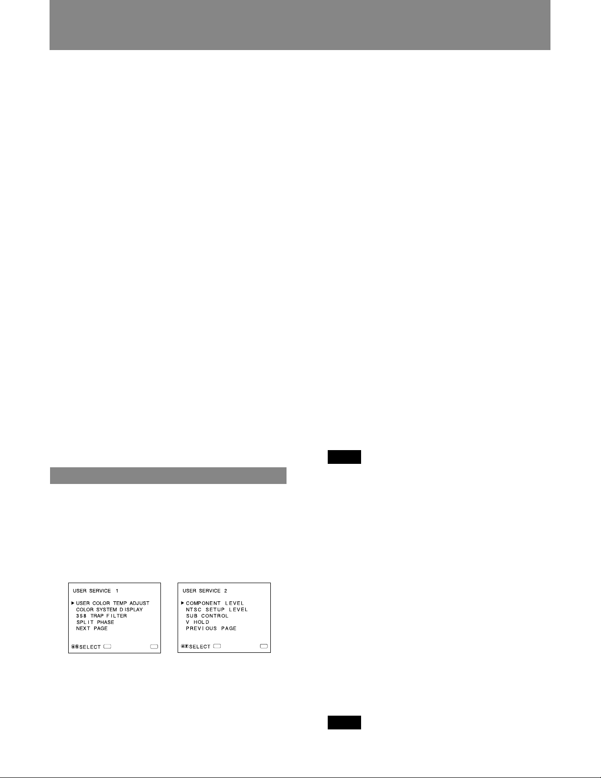
User Service Mode
The user service mode is useful when adjusting the settings
and controls except for the above.
To enter the user service mode, press and hold the MENU
(EXIT) button until the following USER SERVICE 1
appears.
To move to the second page of the mode, select “NEXT
PAGE” and to return to the first page of the menu, select
“PREVIOUS PAGE”.
!£ USER COLOR TEMP ADJUST menu
The value of adjustment in this menu works only when
“USER” is selected in the COLOR TEMP SELECT
menu (2).
ADJUST GAIN:
Adjusts the color balance (gain) of the USER mode.
ADJUST BIAS:
Adjusts the color balance (bias) of the USER mode.
COLOR TEMP RANGE:
When you adjust the color temperature in the USER
mode, select a color temperature range before
adjusting ADJUST GAIN and ADJUST BIAS. If the
adjusted color temperature is between 3200K and
5000K, select “3200K-5000K.” If the adjusted color
temperature is between 5000K and 10000K, select
“5000K-10000K.” [5000K-10000K]
!¢ COLOR SYSTEM DISPLAY menu
Select the color system display mode. In AUTO, the
kind of color system being used appears on the screen
each time you change the signal input. [AUTO]
!∞ 358 TRAP FILTER menu
Color spill or color noise may be eliminated if you
select ON (NTSC signal only). Normally set it to OFF.
[OFF]
!§ SPLIT PHASE menu
When the SPLIT function is activated, if the lower side
picture (the signal fed through the RGB/COMPONENT
B input connectors) has some discrepancy of location
with the upper side picture, adjust the SPLIT PHASE
menu.
Each time you press the >(+) button, the lower side
picture moves left.
Note
When the adjustment is made in the menu, the skew
error will occur on the top of the lower side picture.
!¶ COMPONENT LEVEL menu
Select the component level from among three modes.
N10/SMPTE: for 100/0/100/0 signal
BETA 7.5: for 100/7.5/75/7.5 signal
BETA 0: for 100/0/75/0 signal [BETA 7.5]
!• NTSC SETUP LEVEL menu
Select the NTSC setup level from two modes. The 7.5
setup level is mainly used in north America. The 0 setup
level is mainly used in Japan. [7.5]
10
ENTER
!ª SUB CONTROL screen
You can finely adjust the controls on the front panel.
MENU
ENTER
MENU
CONTRAST, PHASE, CHROMA and BRIGHT
controls have clicks at the center of their adjustment
range. You can adjust the setting of the click position
with this feature.
@º V HOLD screen
Adjust the vertical hold if the picture rolls vertically.
Note
If the rolling of the picture prevents you from watching
the screen, select an input that has nothing connected.
Page 11
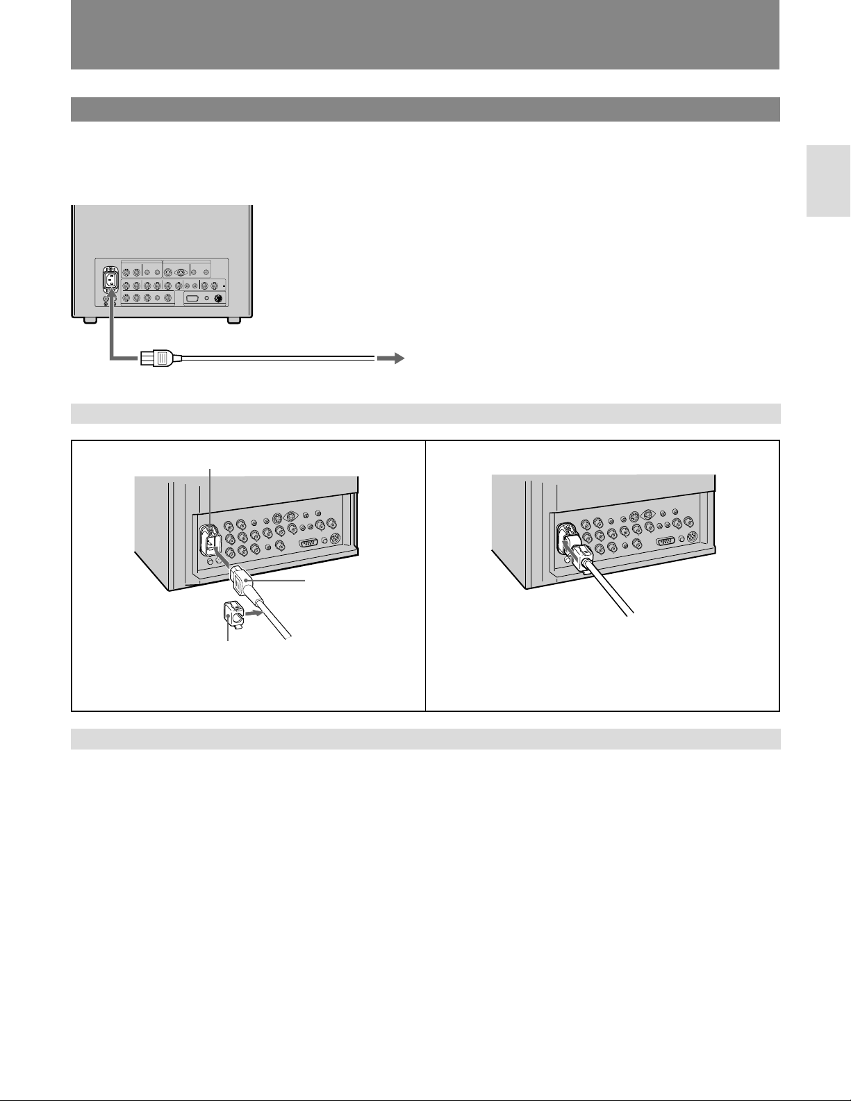
P o wer Sources
House Current
Connect the supplied AC power cord to the AC IN socket
on the rear panel and to a wall outlet.
to AC IN
To connect an AC power cord securely with the AC plug holder
to a wall outlet
12AC IN socket
English
AC power plug
AC plug holder
Plug the power cord into the AC IN socket. Then, attach
the AC plug holder (supplied) on top of the AC power
cord.
To remove the AC power cord
Pull out AC plug holder by squeezing the up and down sides.
Slide the AC plug holder over the cord until it connects
with the attached holder.
11
Page 12
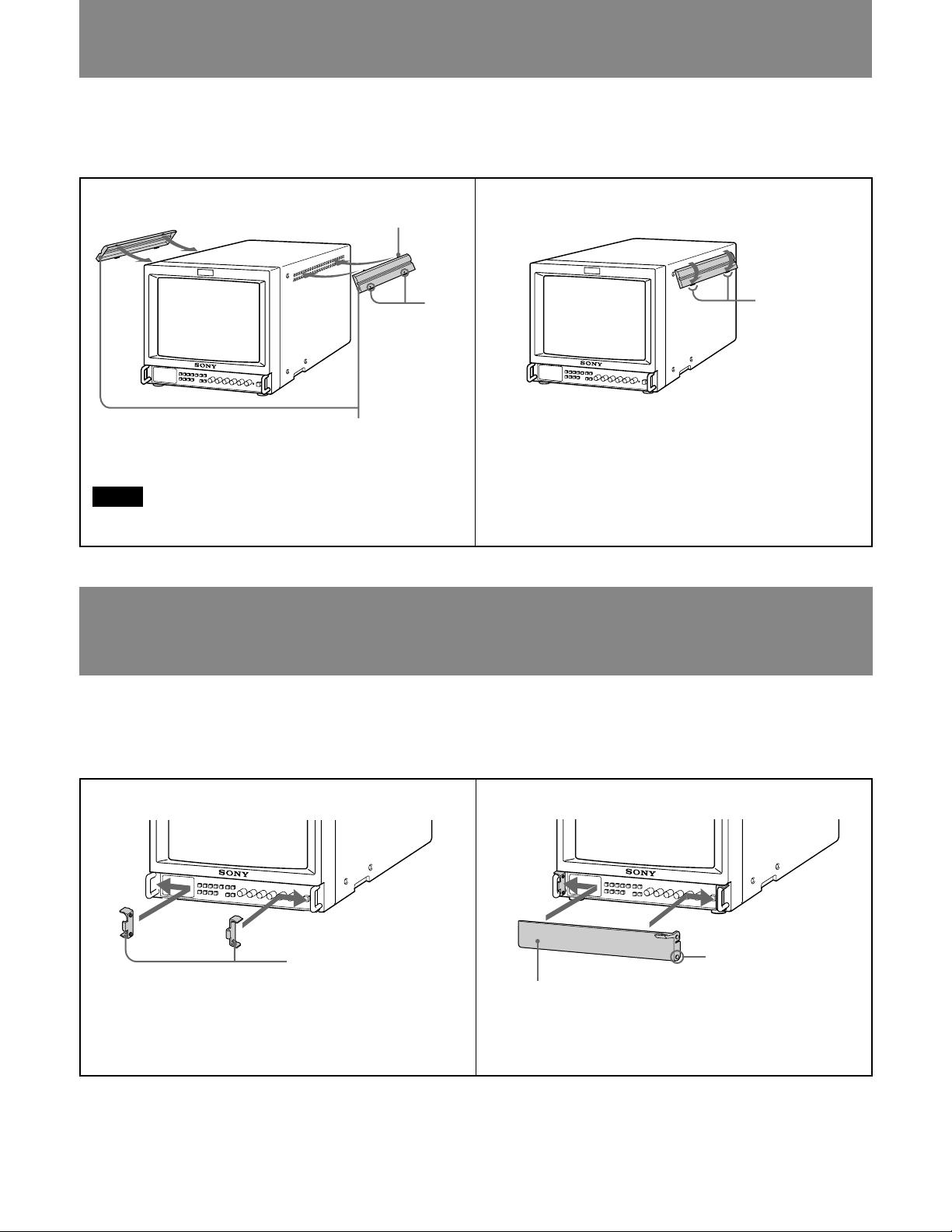
Attaching the Splash Pr oof Cover s
In order to protect the ventilation holes from splashes (of
medicines, etc.), attach the splash proof covers (supplied) as
shown below.
12
Nails on the upper edge
Arrows
Splash proof covers
Making sure the arrows on the cover are facing down,
hook the nails on the upper edge into the ventilation holes.
Note
Attach the splash proof covers to all them ventilation holes.
Push up the nails on the bottom edge and fit the cover into
the lowest ventilation holes.
Attach the both covers to the left and right sides.
Attaching the Contr ol P anel Co ver
In order to protect the control buttons on the front panel
from undesired touching, attach the supplied control panel
cover.
Nails on the
bottom edge
12
Panel hinges
Attach the panel hinges to the left and right grips from the
inner side.
12
Control panel cover
Fit the bosses on the both sides of the control panel cover
into the lower holes of the panel hinges with bending the
control panel cover a little.
Boss
Page 13

Specifications
c
Video signal
Color system NTSC, PAL
Resolution 600 TV lines
Aperture correction 0 dB – +6.0 dB
Frequency response LINE 9.0 MHz (–3 dB)
RGB 10.0 MHz (–3 dB)
Synchronization AFC time constant 1.0 msec.
Picture performance
Overscan 20% overscan of CRT effective
screen area
Normal scan 7% overscan of CRT effective screen
area
Underscan 5% underscan of CRT effective
screen area
Linearity PVM-1353MD
Horizontal: Less than 4% (typical)
Vertical: Less than 4% (typical)
PVM-1953MD
Horizontal: Less than 5% (typical)
Vertical: Less than 5% (typical)
Convergence Central area
0.6 mm (typical) (PVM-1353MD)
0.7 mm (typical) (PVM-1953MD)
Peripheral area
0.8 mm (typical) (PVM-1353MD)
1.3 mm (typical) (PVM-1953MD)
Raster size stability H 1.0%, V 1.5%
High voltage regulation
3.5% (PVM-1353MD)
4.0% (PVM-1953MD)
CRT SMPTE-C phosphor
Color temperature 6500K/5600K/USER (3200K –
10000K, factory setting is 6500K)
Inputs
Y/C IN 4-pin mini DIN connector
See the pin assignment on the
page 14.
VIDEO IN BNC connector 1Vp-p ±6 dB, sync
negative
AUDIO IN phono jack, –5 dBu, more than 47k
ohms
R/R-Y IN, G/Y IN, B/B-Y IN
BNC connector
R, G, B channels 0.7 Vp-p ±6 dB
Sync on green 1 Vp-p Composite sync negative,
75 ohms terminated
R-Y, B-Y channels 0.7 Vp-p ±6 dB
Y channel 1.0 Vp-p ±6 dB
(Standard color bar signal of 75%
chrominance)
EXT SYNC IN BNC connector composite sync
4 Vp-p ±6 dB, negative
Outputs
Y/C OUT 4-pin mini DIN connector, 75 ohms
terminated
VIDEO OUT BNC connector, 75 ohms terminated
AUDIO OUT phono jack
R/R-Y OUT, G/Y OUT, B/B-Y OUT
BNC connector, 75 ohms terminated
EXT SYNC OUT BNC connector, 75 ohms terminated
DC OUT 5 V/1 A
Speaker output Output level 0.8 W
Remote input
REMOTE 1 8-pin mini DIN
See the pin assignment on the
page 14.
RS-232C 9-pin D-sub
See the pin assignment on the
page 14.
General
Classification of equipment
- Type of protection against electric shock
Class I equipment
- Degree of protection against electric shock
Type B equipment
- Degree of protection against harmful ingress of water
Ordinary equipment
- Degree of safety of application in the presence of a
flammable anaesthetic mixture
Not protected equipment
- Mode of operation Continuous operation
- Information concerning type and frequency of technical
maintenance Not need maintenance equipment
- Main power switch Functional switch
Power requirements 120 V AC, 50/60 Hz
1.3 A (PVM-1353MD)
1.6 A (PVM-1953MD)
Capable of 100 to 240V operation
Operating temperature range
0 – +35°C (32 – 95°F)
Storage temperature range
–10 – +40°C (14 – 104°F)
Humidity 0 – 90%
Pressure 860-1060 hpa
Dimensions PVM-1353MD
Approx. 346 · 340 · 411.5 mm
(w/h/d)
(135/8 · 131/2 · 161/4 inches)
PVM-1953MD
Approx. 450 · 457.5 · 503 mm
(w/h/d)
(173/4 · 181/8 · 197/8 inches)
not incl. projecting parts and controls
English
0 dBu = 0.775 Vr.m.s.
(continued)
13
Page 14
Specifications
12345
6789
Mass PVM-1353MD
Approx. 16.7 kg (36 lb 14 oz)
PVM-1953MD
Approx. 30 kg (66 lb 2 oz)
Accessory supplied AC power cord (1)
AC plug holder (1)
Splash proof covers (2)
Control panel cover (1)
Panel hinges (2)
Remote Control Connector
8-pin mini DIN (1)
Operating Instructions (1)
Interface Manual for Programmers (1)
Quick Reference Card (1)
Double-sided adhesive tapes (4)
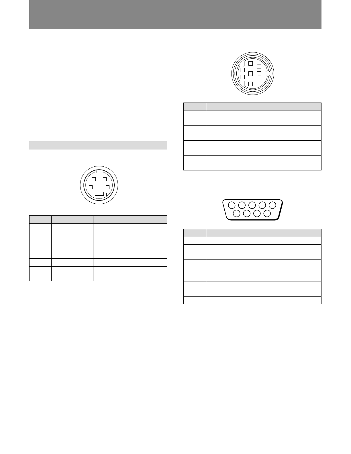
Pin assignment
Y/C IN connector (4-pin mini DIN)
21
34
*
REMOTE 1 connector (8-pin mini DIN)
5
8
2
4
7
1
6
3
Pin No.
Signal
1
REMOTE ON/OFF
2
LINE A
3
GND
4
LINE B
5
TALLY
6
OVER SCAN
7
RGB A
8
RGB B
RS-232C connector (9-pin D-sub)
Pin No.
1
2
3
4
Signal
Y-input
CHROMA subcarrier-input
GND for Y-input
GND for
CHROMA-input
Description
1 Vp-p, sync negative,
75 ohms
300 mVp-p, burst
Delay time between Y and C:
within 0±100 nsec., 75 ohms
GND
GND
Pin No.
1
2
3
4
5
6
7
8
9
Signal
—
RX
TX
—
GND
—
RTS
CTS
—
14
Design and specifications are subject to change without
notice.
Page 15

Français
AVER TISSEMENT
Afin d’éviter tout risque d’incendie ou
d’électrocution, ne pas exposer cet
appareil à la pluie ou à l’humidité.
Des courants de hautes tensions dangereuses sont
présents à l’intérieur de cet appareil. Ne pas ouvrir le coffret.
Se reporter à un personnel qualifié uniquement.
Dans le cas d’une défaillance ou de nécessité d’entretien,
consulter un revendeur Sony autorisé.
Pour les utilisateurs au Canada
Cet appareil numérique de la classe A respecte toutes les
exigences du Réglement sur le matériel brouilleur du
Canada.
Raccordez le cordon d’alimentation à une prise murale
mise à la terre.
Symboles sur l’appareil
Symbole
Type B
Emplacement
Panneau arrière
Panneau frontal
Panneau arrière
A l’intérieur de
l’appareil
Ce symbole indique
Appareil de type B selon les
normes IEC 601-1 sur la
sécurité des appareils
médicaux.
Les appareils de type B
conviennent aux
applications externe et
interne sur le patient à
l’exception des applications
cardiaques directes.
Interrupteur d’alimentation.
Appuyez sur ce bouton pour
mettre le moniteur sous ou
hors tension.
La borne équipotentielle qui
ramène les différentes
parties d’un système à la
même tension.
Présence de tensions
électriques dangereuses
non isolées à l’intérieur de
l’appareil qui sont
susceptibles de provoquer
un risque de choc
électrique.
Français
15
Page 16

Tab le des matières
Précautions
Précautions ....................................................................... 16
Caractéristiques ................................................................ 17
Emplacement et fonction des composants
et des commandes ......................................................... 18
Panneau avant ............................................................... 18
Panneau arrière.............................................................. 20
Utilisation des menus affichés à l’écran ........................... 22
Modes d’alimentation ....................................................... 25
Installation des couvercles antiprojection ........................ 26
Installation du couvercle du panneau de commande ........ 26
Spécifications ................................................................... 27
Sécurité
• Faites uniquement fonctionner l’appareil sur secteur de
120 volts (CA).
• La plaquette signalétique indiquant la tension, la
consommation, etc., est située à l’arrière de l’appareil.
• Si un liquide ou un solide venait à s’introduire à
l’intérieur du châssis, débranchez le cordon
d’alimentation et faites-le vérifier par un technicien
compétent avant de le remettre en service.
• Débranchez l’appareil au niveau de la prise secteur si
vous prévoyez de ne pas l’utiliser pendant plusieurs jours
Précautions
ou davantage.
• Pour débrancher le cordon d’alimentation, saisissez-le par
la fiche et ne tirez jamais sur le cordon proprement dit.
• La prise secteur doit être installée à proximité de
l’appareil et être aisément accessible.
Installation
• Veillez à assurer une circulation d’air suffisante pour
éviter toute surchauffe à l’intérieur de l’appareil.
Ne placez pas l’appareil sur des surfaces textiles (tapis,
couvertures, etc.) ni à proximité de rideaux ou de
draperies susceptibles d’obstruer les orifices de
ventilation.
• N’installez pas l’appareil à proximité de sources de
chaleur comme un radiateur ou une bouche d’air chaud,
ni dans un endroit exposé au rayonnement solaire direct,
à des poussières excessives, à des vibrations ou à des
chocs mécaniques.
Entretien
Pour garder à l’appareil l’aspect du neuf, nettoyez-le
régulièrement à l’aide d’une solution détergente douce.
N’utilisez jamais de solvants tels que de l’alcool ou de
l’essence ni de nettoyants abrasifs sous peine de ternir le
fini de l’appareil. Par mesure de sécurité, débranchez
l’appareil avant de le nettoyer.
Remballage
Conservez le carton d’emballage et les matériaux de
conditionnement, car ils constituent une protection idéale
en vue du transport de l’appareil. Lors du transport de
l’appareil, remballez-le comme illustré sur le carton.
Pour toute question au sujet de cet appareil, consultez un
distributeur Sony agréé.
16
Page 17

Caractéristiques
Image
Tube image Trinitron à HR (Haute Résolution)
Le tube image Trinitron à HR assure une image à haute
résolution. La résolution horizontale est de plus de 600
lignes TV au centre de l’image.
Filtre en peigne
Lorsque des signaux vidéo NTSC sont reçus, le filtre en
peigne entre en service afin d’augmenter la définition et
d’obtenir des images finement détaillées, sans taches de
couleur ni parasites.
Circuit de rétroaction automatique du courant de
faisceau
Le circuit de rétroaction automatique du courant de faisceau
assure une compensation stable des blancs.
Entrées
Quatre systèmes couleur disponibles
Le moniteur peut afficher les signaux PAL et NTSC. Le
système couleur approprié est sélectionné
automatiquement.
Connecteurs d’entrée analogiques RVB/
composant
Les signaux RVB analogiques et composants (Y, R-Y et BY) d’un appareil vidéo peuvent être reçus via ces
connecteurs.
Appuyez sur le sélecteur RGB/COMPONENT A/B sur le
panneau frontal et sélectionnez des signaux de RVB ou de
composante dans le menu à l’écran.
Connecteur d’entrée de luminance chrominance
(Y/C) (connecteur S INPUT)
Le signal vidéo, divisé en signal de luminance (Y) et en
signal de chrominance (C), peut être reçu via ce connecteur,
ce qui a pour effet d’éliminer les interférences entre les
deux signaux qui ont tendance à apparaître dans un signal
vidéo composite et de garantir la qualité des images.
Connecteurs d’entrée de synchronisation externe
Lorsque le signal RGB externe ou le signal de composante
est entré et que le signal de synchronisation est réglé sur
externe dans le menu à l’écran, le moniteur peut être utilisé
sur le signal de synchronisation fourni par un générateur de
synchronisation externe.
Terminaison automatique
(uniquement les connecteurs avec marque )
Les connecteurs d’entrée BNC du panneau arrière sont
terminés à 75 ohms à l’intérieur, dans le cas où aucun
cordon n’est raccordé aux connecteurs de sortie en boucle
directe.
Lorsqu’un câble est branché sur le connecteur de sortie de
type BNC, la terminaison de 75 ohms est retirée
automatiquement.
Fonctions
Menus affichés sur l’écran
Vous pouvez régler les paramètres température couleur,
REGLAGE CHROMA, etc., au moyen des menus affichés
sur l’écran.
Mode de surbalayage
Le format d’affichage est élargi d’approximativement 20%
et la partie centrale de l’écran offre un confort de
visualisation accru.
Mode de sous-balayage
Le signal normalement balayé en-dehors de l’écran peut
être surveillé en mode de sous-balayage.
Remarque
Les lignes de balayage RVB sombres qui peuvent
apparaître sur le bord supérieur de l’écran lorsque le
moniteur se trouve en mode de sous-balayage sont causées
par un signal d’essai interne et non par le signal d’entrée.
Fonction de division
L’affichage se divise en deux parties (supérieure et
inférieure). La partie supérieure de l’écran affiche le signal
des connecteurs d’entrée RGB/COMPONENT A et la
partie inférieure le signal des connecteurs d’entrée RGB/
COMPONENT B. Vous pouvez comparer les deux écrans.
Décodeur de sous-titres
Lorsqu’un signal comprenant des sous-titres est entré, les
sous-titres sont incrustés sur l’écran. Vous pouvez
sélectionner OUI ou NON et régler le type de sous-titres
dans l’écran de menu.
Démagnétisation automatique/manuelle
La démagnétisation de l’image peut se faire
automatiquement lorsque l’alimentation est enclenchée ou
alors manuellement en appuyant sur la touche DEGAUSS.
Cinq langues d’affichage des menus
Vous pouvez sélectionner l’une des cinq langues
d’affichage des menus à l’écran.
Couvercle(s) antiprojection et couvercle de
panneau de commande
Des couvercles antiprojection protégeant les ouïes de
ventilation contre les projections (de médicaments, etc.) et
un couvercle de panneau de commande protégeant les
touches de commande contre les manipulations
intempestives sont fournis.
Carte de référence rapide
La carte d’utilisation est destinée à vous aider à comprendre
la configuration du menu ainsi que la méthode
d’exploitation. Vous pouvez fixer les bandes adhésives
double face fournies à l’arrière de la carte.
Montage sur étagère de 19 pouces de normes EIA
Le moniteur peut être installé sur une étagère de 19 pouces
de normes EIA moyennant l’adaptation d’un rail-glissière
MB-502B (pour PVM-1353MD) ou SLR-103 (pour
PVM-1953MD) (non fournis). Pour les détails relatifs au
montage, voir le mode d’emploi de l’adaptation d’un railglissière.
17
Français
Page 18

Emplacement et fonction des composants et des
commandes
Panneau avant
RESET
RGB/COMPONENT
A
B
UNDER
OVER
SCAN
SCAN
SPLIT
MENU
EXIT
SELECT
ENTER
LINE
AB
DEGAUSS
1 Témoin de signalisation
L’indicateur s’allume dès que la caméra vidéo raccordée
à cet appareil est sélectionnée. indiquant par là que les
images sont enregistrées. Il faut alors utiliser la
connexion de commande de l’indicateur.
Pour l’attribution des broches, reportez-vous aux
“Spécifications” à la page 28.
2 U Interrupteur et indicateur de mise sous tension
(POWER)
Appuyez sur cet interrupteur pour mettre le moniteur
sous tension. L’indicateur s’allume en vert. Appuyez à
nouveau sur cet interrupteur pour mettre le moniteur
hors tension.
3 Indicateur de la telecommande (REMOTE)
Cet indicateur s’allume dans les conditions suivantes:
— Réglez PREREGLAGE sur OUI dans le menu.
— Réglez TELECOMMANDE (RS-232C) sur
TELECOMMANDE UNIQUEMENT ou
TELECOMMANDE & LOCAL dans le menu.
— Réglez REMOTE ON via la borne REMOTE 1.
APERTURE
MIN
MAX
POWER
REMOTE
–+
MIN
CONTRAST
PHASECHROMABRIGHT
MAX
PUR GRN MIN MAX MIN MAX
VOLUME
5 > Réglage du contraste (CONTRAST)
Tournez cette commande dans le sens des aiguilles
d’une montre pour augmenter le contraste de l’image et
dans le sens contraire pour le diminuer.
6 Réglage de phase (PHASE)
Cette commande n’est opérationnelle que pour le
système couleur NTSC. Tournez dans le sens des
aiguilles d’une montre pour faire virer la couleur chair
au vert et dans le sens contraire pour la rendre plus
rouge.
7 ¯ Réglage de la chrominance (CHROMA)
Tournez dans le sens des aiguilles d’une montre pour
augmenter l’intensité des couleurs et dans le sens
contraire pour la diminuer.
8 ¨ Réglage de la luminosité (BRIGHT)
Tournez dans le sens des aiguilles d’une montre pour
augmenter la luminosité et dans le sens contraire pour la
diminuer.
4 ¸ Réglage du volume (VOLUME)
Tournez cette commande dans le sens des aiguilles
d’une montre ou dans le sens contraire pour obtenir le
volume désiré.
18
Page 19

c
9 Œ Réglage d’ouverture (APERTURE)
Tournez dans le sens des aiguilles d’une montre pour
augmenter la netteté de l’image et dans le sens contraire
pour la diminuer.
Lorsque la commande est réglée sur MIN, l’image
devient plate et ne nécessite aucune correction.
Remarque
Les réglages APERTURE, CHROMA, PHASE n’ont
aucun effet sur les images des signaux RVB.
0 Touche de menu (sortir) (MENU(EXIT))
Appuyez sur cette touche pour faire apparaître le menu.
Appuyez à nouveau pour revenir à l’écran précédent
dans le menu.
!¡ Touche d’entrée (séléctionner) (ENTER(SELECT))
Appuyez sur cette touche pour sélectionner un
paramètre dans le menu.
!™ Touches >(+)/.(–)
Appuyez sur ces touches pour déplacer le curseur (z)
ou régler le paramètre sélectionné dans les menus.
!£ Touche de surbalayage (OVERSCAN)
Appuyez sur cette touche (témoin allumée) pour activer
le surbalayage. Le format d’affichage est alors élargi
d’approximativement 20% et la partie centrale de
l’écran offre un confort de visualisation accru. En
appuyant une nouvelle fois sur cette touche, la taille
d’affichage revient à la condition normale (témoin
éteint).
!• Sélecteurs de RVB/composante A/B
(RGB/COMPONENT A/B)
Appuyez sur ces sélecteurs pour sélectionner un signal
(témoin allumée).
A: Appuyez sur A pour contrôler le signal des
connecteurs d’entrée RGB/COMPONENT A.
B: Appuyez sur B pour contrôler le signal des
connecteurs d’entrée RGB/COMPONENT B.
!ª Touche de division (SPLIT)
Lorsque vous sélectionnez les signaux des connecteurs
d’entrée RGB/COMPONENT A et RGB/
COMPONENT B, appuyez sur cette touche (témoin
allumée) pour diviser l’écran en deux parties (supérieure
et inférieure) et contrôler simultanément les deux
signaux RGB.
Remarque
Assurez-vous que les signaux transmis via les
connecteurs RGB/COMPONENT A et RGB/
COMPONENT B sont synchronisés.
Français
!¢ Touche de sous-balayage (UNDERSCAN)
Appuyez sur cette touche (témoin allumé) pour procéder
au sous-balayage. Les dimensions de l’affichage sont
réduites de 5% environ, de sorte que les quatre coins de
la trame sont visibles. En appuyant une nouvelle fois sur
cette touche, la taille d’affichage revient à la condition
normale (témoin éteint).
!∞ Touche de restauration (RESET)
Pendant les réglages de menu, appuyez sur cette touche
pour restaurer le réglage dans le menu.
!§ Touche de démagnétisation (DEGAUSS)
Enclenchez cette touche momentanément. L’écran va
être démagnétisé.
Attendez 10 minutes avant de réenclencher cette touche.
Remarque
Pendant que l’écran est démagnétisé, l’image défile
verticalement.
!¶ Sélecteurs de ligne A/B (LINE A/B)
Appuyez sur ces sélecteurs pour sélectionner un signal
(témoin allumée).
A: Appuyez sur A pour contrôler le signal des
connecteurs d’entrée LINE A.
B: Appuyez sur B pour contrôler le signal des
connecteurs d’entrée LINE B.
19
Page 20

Emplacement et fonction des composants et des commandes
Panneau arrière
AC IN
VIDEO AUDIO
R/R–Y G/Y B/B–Y
A
IN
R/R–Y
B
IN
LINE A
OUT IN OUT IN OUT IN OUT IN OUT
G/Y B/B–Y
IN IN
RGB/COMPONENT
1 Prise d’alimentation (AC IN)
Connectez le cordon d’alimentation secteur fourni à cette
prise.
2 Connecteurs de ligne LINE A
Les connecteurs d’entrée de ligne pour les signaux
vidéo composites et les signaux audio ainsi que leurs
connecteurs de sortie en boucle passante.
Pour contrôler le signal d’entrée de ces connecteurs,
appuyez sur le sélecteur LINE A (témoin allumé) sur le
panneau frontal.
VIDEO IN (BNC)
Raccordez ce connecteur à la sortie vidéo d’un appareil
vidéo tel qu’un magnétoscope ou une caméra vidéo
couleur. Pour une connexion en boucle directe,
raccordez-le à la sortie vidéo d’un autre moniteur.
VIDEO OUT (BNC)
Sortie en boucle directe du connecteur VIDEO IN.
Raccordez ce connecteur à l’entrée vidéo du
magnétoscope ou d’un autre moniteur.
Lorsque le câble est branché à ce connecteur, la
terminaison de 75 ohms de l’entrée est relâchée
automatiquement et le signal entré au connecteur
VIDEO IN sort via ce connecteur.
AUDIO IN (prise phono)
Raccordez ce connecteur à la sortie audio d’un
magnétoscope ou d’un microphone par l’intermédiaire
d’un amplificateur de microphone approprié. Pour une
connexion en boucle directe, raccordez ce connecteur à
la sortie audio d’un autre moniteur.
20
IN OUTIN OUT
EXT SYNC
AUDIO
IN IN
Y/C
IN OUT
(La marque indique la terminaison automatique.)
LINE B
IN OUT
AUDIO
RS-232C
AUDIO
REMOTE
EXT SYNC
5V/1A
REMOTE 1DC OUT
AUDIO OUT (prise phono)
Sortie en boucle directe de la prise AUDIO IN.
Raccordez ce connecteur à la sortie audio d’un
magnétoscope ou d’un autre moniteur.
3 Connecteurs de ligne LINE B
Connecteurs d’entrée Y/C séparés, connecteurs d’entrée
audio et connecteurs de sortie en boucle passante
correspondants.
Pour contrôler le signal d’entrée de ces connecteurs,
appuyez sur le sélecteur LINE B (témoin allumé) sur le
panneau frontal.
Y/C IN (miniconnecteur DIN à 4 broches)
Raccordez à la sortie distincte Y/C d’un magnétoscope,
d’une caméra vidéo ou d’un autre appareil vidéo.
Y/C OUT (miniconnecteur DIN à 4 broches)
Sortie en boucle directe du connecteur Y/C. Raccordez
à l’entrée distincte Y/C d’un magnétoscope ou d’un
autre moniteur.
Lorsque le câble est branché à ce connecteur, la
terminaison de 75 ohms de l’entrée est relâchée
automatiquement et le signal entré au connecteur Y/C
IN sort via ce connecteur.
AUDIO IN (prise phono)
Raccordez au connecteur de sortie audio d’un
magnétoscope ou d’un microphone via un amplificateur
de microphone approprié. Pour une connexion en boucle
passante, raccordez au connecteur de sortie audio de
l’autre moniteur.
AUDIO OUT (prise phono)
Sortie en boucle directe du connecteur AUDIO IN.
Raccordez à l’entrée audio d’un magnétoscope ou d’un
autre moniteur.
Page 21

4 Connecteurs de signal RVB, composante A (RGB/
COMPONENT A)
Connecteurs d’entrée du signal RVB du signal de
composante ainsi que leurs connecteurs de sortie en
boucle passante.
Pour contrôler le signal d’entrée de ces connecteurs,
appuyez sur le sélecteur RGB/COMPONENT A
(témoin allumé) sur le panneau frontal.
Sélectionnez ensuite un des quatre éléments du menu
SYSTEM RVB A pour régler le signal RVB (RGB) ou
du COMP(composant) et le signal de SYNC INT
(synchronisation interne) ou SYNC EXT
(synchronisation externe).
Pour le pilotage des menus, voir pages 24 à 26.
R/R-Y IN, G/Y IN, B/B-Y IN (BNC)
Si “RVB-SYNC INT” ou “COMP-SYNC INT” est
sélectionné dans le menu, le moniteur utilise le signal de
synchronisation du canal G/Y.
Pour contrôler le signal RGB.
Raccordez aux sorties analogiques de signal RVB d’une
caméra vidéo.
Pour contrôler le signal composant.
Raccordez aux sorties de signal composant R-Y/Y/B-Y
d’une caméra vidéo Betacam SPTM Sony.
6 Connecteurs de signal RVB, composante B (RGB/
COMPONENT B)
Connecteurs d’entrée du signal RVB ou du signal de
composante.
Pour contrôler le signal d’entrée de ces connecteurs,
appuyez sur le sélecteur RGB/COMPONENT B (témoin
allumée) sur le panneau frontal.
Sélectionnez ensuite un des quatre éléments du menu
SYSTEM RVB B pour régler le signal RVB (RGB) ou
du COMP(composant) et le signal de SYNC INT
(synchronisation interne) ou SYNC EXT
(synchronisation externe).
Pour le pilotage des menus, voir pages 24 à 26.
R/R-Y IN, G/Y IN, B/B-Y IN (BNC)
Si “RVB-SYNC INT” ou “COMP-SYNC INT” a été
sélectionné dans le menu RGB B SYSTEM, le moniteur
utilise le signal de synchronisation du canal G/Y.
Pour contrôler le signal RVB
Raccordez aux connecteurs de sortie du signal RVB
analogique d’une caméra vidéo.
Pour contrôler le signal de composante
Raccordez aux connecteurs de sortie des signaux de
composantes R-Y/Y/B-Y d’une caméra vidéo Sony
Betacam SP.
Français
R/R-Y OUT, G/Y OUT, B/B-Y OUT (BNC)
Sorties en boucle directe des connecteurs R/R-Y IN, G/
Y IN, B/B-Y IN.
Lorsque les câbles sont branchés sur ces connecteurs, la
terminaison de 75 ohms de l’entrée est relâchée
automatiquement et le signal entré via/es connecteurs R/
R-Y IN, G/Y IN, B/B-Y IN sort via ces connecteurs.
Pour appliquer le signal RGB
Raccordez aux entrées analogiques de signal RVB
d’une imprimante vidéo ou d’un autre moniteur.
Pour appliquer le signal composant
Raccordez aux entrées de signal le composant R-Y/Y/BY d’un caméscope Betacam SP Sony.
AUDIO IN (prise phono)
Raccordez à la sortie audio d’un appareil vidéo lorsque
le signal analogique RVB ou composant est entré.
AUDIO OUT (prise phono)
Sortie en boucle directe du connecteur AUDIO IN.
EXT SYNC IN (BNC)
Lorsque ce moniteur fonctionne sur un signal de
synchronisation externe, connectez le signal d’un
générateur de synchronisation à ce connecteur.
Pour utiliser le signal de synchronisation de ce
connecteur, sélectionnez “RVB-SYNC EXT” ou
“COMP-SYNC EXT” dans le menu SYSTEM RVB A.
EXT SYNC OUT (BNC)
Sortie en boucle directe du connecteur EXT SYNC IN.
Raccordez ce connecteur à l’entrée de synchronisation
externe de l’appareil vidéo à synchroniser avec ce
moniteur.
Lorsque le câble est branché sur ce connecteur, la
terminaison de 75 ohms de l’entrée est relâchée et le
signal entré via le connecteur EXT SYNC IN sort via ce
connecteur.
5 Borne de terre (1/<)
Raccordez un câble de terre.
AUDIO IN (prise phono)
Raccordez au connecteur de sortie audio de
l’équipement vidéo si le signal RVB analogique ou le
signal de composante est entré via ce connecteur.
EXT SYNC IN (BNC)
Si ce moniteur fonctionne sur un signal de
synchronisation externe, raccordez le signal d’un
générateur de synchronisation à ce connecteur.
Pour utiliser le signal de synchronisation entré par ce
connecteur, sélectionnez “RVB-SYNC EXT” ou
“COMP-SYNC EXT” dans le menu SYSTEM RVB B.
7 Connecteurs de telecommande (REMOTE)
RS-232C (D-sub à 9 broches)
Raccordez à un connecteur RS-232C de l’autre
équipement Vous pouvez utiliser le moniteur avec la
commande de l’autre équipement.
Pour plus de détails, voir la liste de Mode d’emploi
d’interface pour programmeurs (Interface Manual for
Programmers).
REMOTE 1 (miniconnecteur DIN à 8 broches)
Raccordez au connecteur de sortie de commande d’une
console de commande, d’un générateur d’effets
spéciaux, etc. L’indicateur de signalisation du panneau
frontal sera activé et désactivé par l’équipement
raccordé.
Ce connecteur vous permet également de raccorder une
commande à distance.
Pour l’attribution des broches, reportez-vous aux
“Spécifications” à la page 28.
Connecteur DC OUT 5V/1A
Vous pouvez utiliser ce connecteur comme source
d’alimentation pour l’autre équipement.
Sortie de 5V CC/1A.
21
Page 22

Utilisation des menus affic hés à l’écran
Configuration du menu
L’organigramme montre les différents niveaux des menus
affichés à l’écran que vous pouvez utiliser pour effectuer
Les menus suivants apparaissent quand vous sélectionnez le
mot “FRANÇAIS” dans le menu LANGUAGE (!¡).
les différents réglages et ajustements.
Pour les détails de chaque menu, reportez-vous aux pages
23 et 24.
1 Menu principal 2 Menu SELECT TEMP COULEUR
ENTER
MENU
3 Menu SOUS-TITRAGE
4 Menu PREREGLAGE
ENTER
ENTER
MENU
MENU
Mode réglage utilisateur
ENTER
6 Ecran AJUST NIV PREREGLES
ENTER
5 Menu CONFIG
MENU
7 Menu REGLAGE CHROMA
!™ Ecran
REGLAGE
8 Menu SYSTEM RVB A
AUTO
9 Menu SYSTEM RVB B
!º Menu TELECOMMANDE (RS-232C)
ENTER
MENU
!¡ Menu LANGUE
!£ Menu REGL TEMP COUL UTILISAT
!¢ Menu AFF SYSTEME COULEUR
!∞ Menu FILTRE PIEGE 385
MENU
!§ Menu DIVISION PHASE
!¶ Menu NIV COMPOSANTES
!• Menu NIV NOMINAL NTSC
!ª Ecran REGLAGE SECONDAIRE
22
ENTER
MENU
@º Ecran STABILITE VERTICALE
Page 23

c
A
M
Utilisation des menus
Le panneau frontal comporte cinq touches destinées à
l’exploitation des menus. Pour afficher le menu principal,
appuyez en premier lieu sur MENU (EXIT). Les touches
que vous pouvez utiliser apparaissent dans le bas de l’écran
de menu.
Fonctions des touches
RGB/COMPONENT
RESET
BLUE
ONLY
Touche
RESET
ABB SPLIT
UNDER
SCAN
OVER
SCAN
MENU
EXIT
SELECT
ENTER
Touches d’utilisation
des menus
Le sommaire des menus
Les phrases ci-dessous indiquent les éléments détaillés de
chaque menu.
[ ] indique la position du réglage par défaut.
1 Menu principal
Sélectionnez une option et appuyez sur ENTER
(SELECT) pour passer au menu suivant.
2 Menu SELECT TEMP COULEUR
Sélectionnez la température de couleur entre 6500K,
5600K et UTILISATEUR. Le réglage par défaut du
paramètre UTILISATEUR est de 6500K. Vous pouvez
régler ou modifier la température de couleur dans le
mode UTILISATEUR (un instrument de mesure est
requis). [6500K]
Remarque
La température de couleur du mode UTILISATEUR
peut être réglée dans la plage allant de 3200K à 10000K.
Vous pouvez régler la température de couleur du mode
UTILISATEUR dans le menu REGL TEMP COUL
UTILISAT (!£) du mode de sarvice utilisateur.
Pour plus de détails, voir le “Menu REGL TEMP
COUL UTILISAT (!£)” à la page 24.
Français
Touche
MENU
EXIT
ENTER
SELECT
>
+
–
.
RESET
Pour sélectionner
une option de menu
retourner au menu
précédent.
déterminer une
option sélectionnée.
déplacer le curseur
(z) vers le haut.
déplacer le curseur
(z) vers le bas.
Pour régler l’option de
menu sélectionnée
retourner au menu
précédent.
sélectionner une option.
diminuer la valeur
sélectionnée.
augmenter la valeur
sélectionnée.
ramener le réglage de la
valeur au réglage par
défaut.
(Les éléments imprimés en caractères blancs correspondent
aux inscriptions dans le menu.)
3 Menu SOUS-TITRAGE
Pour afficher les sous-titres, sélectionnez OUI et le type
de sous-titres de votre choix. [NON]
4 Menu PREREGLAGE
Vous pouvez présélectionner chaque commande au niveau
désiré et le mémoriser. Si vous réglez PREREGLAGE sur
OUI, le témoin REMOTE s’allume et les commandes du
panneau frontal ne sont plus opérationnelles. Le moniteur
fonctionne avec les paramètres de mémoire interne. Pour le
réglage, sélectionnez AJUST NIV PREREGLES. [NON]
5 Menu CONFIG
Choisissez un élément pour régler le moniteur.
6 Ecran AJUST NIV PREREGLES
Réglez CONTRAST, BRIGHT, CHROMA, PHASE,
VOLUME, APERTURE sous PREREGLES.
7 Menu REGLAGE CHROMA
Réglez sur OUI pour ajuster le décodeur interne pour
CHROMA et PHASE (signal NTSC uniquement) après
REGLAGE AUTO (!™). [NON]
8 Menu SYSTEM RVB A
Pour contrôler le signal des connecteurs RGB/
COMPONENT A, réglez le signal RVB(RGB) ou de
COMP(composant) et le signal de SYNC INT
(synchronisation interne) ou SYNC EXT (synchronisation
externe) sur ce menu. [RVB-SYNC EXT]
9 Menu SYSTEM RVB B
Pour contrôler le signal des connecteurs RGB/
COMPONENT B, réglez le signal RVB(RGB) ou de
COMP(composant) et le signal de SYNC INT
(synchronisation interne) ou SYNC EXT (synchronisation
externe) sur ce menu. [RVB-SYNC EXT]
23
Page 24

Utilisation des menus affichés à l’écran
!º Menu TELECOMMANDE(RS-232C)
Sélectionnez l’un des trois modes suivants.
TELECOMMANDE DESACTIVEE:
Vous pouvez ajuster les réglages et les commandes à
l’aide des touches du panneau frontal.
Le connecteur RS-232C sont inopérantes.
TELECOMMANDE UNIQUEMENT:
Vous pouvez ajuster les réglages et les commandes
via le connecteur RS-232C.
A l’exception des touches de commande, les touches
et réglages du panneau frontal sont inopérantes.
TELECOMMANDE & LOCAL:
Vous pouvez ajuster les réglages et les commandes à
l’aide du connecteur RS-232C et les touches du
panneau frontal.
Les réglages du panneau frontal sont inopérantes.
[TELECOMMANDE DESACTIVEE]
!¡ Menu LANGUE
Vous pouvez sélectionner la langue utilisée pour les
menus affichés à l’écran dans les cinq langues suivantes
(anglais, allemand, français, italien, espagnol).
[ENGLISH]
!™ Ecran REGLAGE AUTO
Sélectionnez le signal de barre de couleur (full, SMPTE,
EIA) et appuyez sur ENTER(SELECT) pour activer le
réglage automatique de CHROMA et de PHASE. Pour
valider ces réglages, vous devez sélectionner OUI dans
REGLAGE CHROMA (7) .
Mode réglage utilisateur
Le mode de service utilisateur s’avêre bien pratique lons de
l’ajustage des réglages et des commandes à l’exception de
ce qui est précisé ci-dessus.
Pour activer le mode de service utilisateur, pressez et
maintenez la touche MENU (EXIT) enfoncée jusqu’à ce
que le mode SERVICE UTILISATEUR 1 suivant apparaisse.
Pour passer à la seconde page, sélectionnez “PAGE
SUIVANTE” et pour revenir à la première page du mode,
sélectionnez “PAGE PRECEDENTE”.
PLAGE TEMP COULEUR:
Lorsque vous réglez la plage de température des
couleurs dans le mode UTILISATEUR, sélectionnez
une plage de température avant de procéder au
réglage REGLAGE GAIN et REGLAGE BIAS. Si la
température de couleur réglée est comprise entre
3200 et 5000 K, sélectionnez “3200K – 5000K”. Si
la température de couleur réglée est comprise entre
5000 et 10000K, sélectionnez “5000K – 10000K”.
[5000K – 10000K]
!¢ Menu AFF SYSTEME COULEUR
Sélectionnez le mode d’affichage du système couleur.
En mode AUTO, le type de système couleur utilisé
apparaît à l’écran chaque fois que vous changez de
signal d’entrée. [AUTO]
!∞ Menu FILTRE PIEGE 358
Vous pouvez éliminer les distorsions de la couleur en
choisissant OUI (signal NTSC uniquement). Autrement,
réglez-le sur NON. [NON]
!§ Menu DIVISION PHASE
Lorsque la fonction SPLIT a été activée, réglez le menu
DIVISION PHASE si la partie inférieure de L’image (le
signal transmis via les connecteurs d’entrée RGB/
COMPONENT B) est légèrement décalée par rapport à
la partie supérieure de l’image.
Chaque fois que vous appuyez sur la touche > (+), la
partie inférieure de l’image se déplace vers la gauche.
Remarque
Si le réglage est effectué dans le menu, le désalignement
apparaît dans le haut de l’image inférieure.
!¶ Menu NIV COMPOSANTES
Sélectionnez le niveau de composant parmi les trois
modes.
N10/SMPTE: pour un signal 100/0/100/0
BETA 7.5: pour un signal 100/7.5/75/7.5
BETA 0: pour un signal 100/0/75/0 [BETA 7.5]
!• Menu NIV NOMINAL NTSC
Sélectionnez le niveau de réglage NTSC entre les deux
modes. Le niveau de réglage 7.5 est utilisé
essentiellement en Amérique du Nord. Le niveau de
réglage 0 est utilisé essentiellement au Japon. [7.5]
ENTER
MENU
ENTER
!£ Menu REGL TEMP COUL UTILISAT
La valeur de réglage dans ce menu est uniquement
opérante lorsque le paramètre “UTILISATEUR” est
sélectionné dans le menu SELECT TEMP COULEUR
(2).
REGLAGE GAIN:
Permet de régler la balance des couleurs (gain) du
mode UTILISATEUR.
REGLAGE BIAS:
Permet de régler la balance des couleurs
(polarisation) du mode.
24
!ª Ecran REGLAGE SECONDAIRE
Le panneau frontal permet d’effectuer des réglages fins.
MENU
Les commandes CONTRAST, PHASE, CHROMA et
BRIGHT comportent un point dur au centre de la plage
de réglage. Ce dispositif permet de régler le point dur.
@º Ecran STABILITE VERTICALE
Réglez la synchronisation verticale si l’image défile
verticalement.
Remarque
Lorsque le défilement de l’image vous empêche de
visualiser un écran, sélectionnez l’entrée qui n’est pas
connectée.
Page 25

Modes d’alimentation
Alimentation secteur
Branchez le cordon d’alimentation fourni sur la prise AC
IN située sur le panneau arrière et à une prise murale.
Français
á AC IN
Mise en place d’une bague de sécurité sur le câble d’alimentation
12
Insérez le câble d’alimentation dans la prise secteur du
moniteur, puis fixez la bague de sécurité (fournie) sur le
câble.
prise d’alimentation
Bague de sécurité
vers la prise murale
Fiche secteur
Faites coulisser la bague contre la prise.
Pour débrancher le cordon d’alimentation
Retirez le support de fiche d’alimentation en pinçant les
côtés supérieur et inférieur.
25
Page 26

Installation des couverc les antipr ojection
Pour protéger les ouïes de ventilation contre les projections
(de médicaments, etc.), installez les couvercles
antiprojection (fournis) comme illustré ci-dessous.
1
Couvercles antiprojection
Assurez-vous que les flèches sur le couvercle sont
orientées vers le bas et introduisez les onglets sur le bord
supérieur dans les ouïes de ventilation.
Remarque
Installez les couvercles antiprojection sur toutes les ouïes
de ventilation.
Onglets sur le
bord supérieur
Flèches
2
Onglets du bord
inférieur
Enfoncez les onglets du bord inférieur pour fixer le
couvercle dans les trous de ventilation inférieurs.
Installez les deux couvercles sur les côtés gauche et droit.
Installation du couverc le du panneau de
commande
Pour protéger le panneau frontal contre les manipulations
intempestives, installez le couvercle de panneau de
commande fourni.
12
Protubérance
Charnières de panneau
Fixez les charnières de panneau de l’intérieur sur les
poignées gauche et droite.
Couvercle du panneau de commande
Emboîtez les protubérances de chaque côté du couvercle du
tableau de commande dans les deux trous des charnières du
panneau en pliant légèrement le couvercle du tableau de
commande.
26
Page 27

Spécifications
c
Signal vidèo
Système couleur NTSC, PAL
Résolution 600 lignes TV
Correction d’ouverture
0 dB – +6,0 dB
Réponse de fréquence LINE 9,0 MHz (–3 dB)
RGB 10,0 MHz (–3 dB)
Synchronisation Constante de temps AFC: 1,0 ms
Performance de l’image
Surbalayage Surbalayage de 20% de la zone
effective du tube image
Balayage normal Surbalayage de 7% de la zone
d’écran effective du tube cathodique
Sous-balayage Sous-balayage de 5% de la zone
d’écran effective du tube cathodique
Linéarité PVM-1353MD
Horizontale: Moins de 4%
(typique)
Verticale: Moins de 4% (typique)
PVM-1953MD
Horizontale: Moins de 5%
(typique)
Verticale: Moins de 5% (typique)
Linéarité verticale Moins de 7,0% (typique)
Convergence Zone centrale:
0,6 mm (typique) (PVM-1353MD)
0,7 mm (typique) (PVM-1953MD)
Zone périphérique:
0,8 mm (typique) (PVM-1353MD)
1,3 mm (typique) (PVM-1953MD)
Stabilité des dimensions de la trame
H: 1,0%, V: 1,5%
Régulation de haute tension
3,5% (PVM-1353MD)
4,0% (PVM-1953MD)
Ecran à tube cathodique
Phosphore SMPTE-C
Température de couleur
6500K/5600K/UTILISATEUR
(3200K – 10000K Réglage par
défaut = 6500K.)
Entées
Y/C IN miniconnecteur DIN à 4 broches
Voir l’attribution des broches à la
page 28.
VIDEO IN connecteur BNC 1 Vp-p ±6 dB, sync
négative
AUDIO IN prise phono, –5 dBu, plus de 47
kilohms
R/R-Y IN, G/Y IN, B/B-Y IN
connecteur BNC
Chaînes R, G, B 0,7 Vp-p ±6 dB
Sync sur vert 1 Vp-p, Sync composite, négative,
terminé à 75 ohms
Chaînes R-Y, B-Y 0,7 Vp-p ±6 dB
Chaîne Y 1,0 Vp-p ±6 dB
(Signal de barre couleur standard de
chrominance à 75%)
EXT SYNC IN connecteur BNC
Sync composite 4 Vp-p ±6 dB, négative
Sorties
Y/C OUT miniconnecteur DIN à 4 broches,
terminé à 75 ohms
VIDEO OUT connecteur BNC, terminé à 75 ohms
AUDIO OUT prise phono
R/R-Y OUT, G/Y OUT, B/B-Y OUT
connecteur BNC, terminé à 75 ohms
EXT SYNC OUT connecteur BNC, terminé à 75 ohms
Sortie d’un haut-parleur
DC OUT 5 V/1 A
Niveau de sortie 0,8 W
Entrée de commande à distance
REMOTE 1 miniconnecteur DIN à 8 broches
Voir l’attribution des broches à la
page 28.
RS-232C D-sub à 9 broches
Voir l’attribution des broches à la
page 28.
Données générales
Classification de l’équipement
- Type de protection contre les décharges électriques
équipement de classe I
- Degré de protection contre les décharges électriques
équipement de type B
- Degré de protection contre la pénétration néfaste d’eau
équipement ordinaire
- Degré de sécurité d’utilisation en présence de substances
anesthésiantes inflammables
équipement non protégé
- Mode de fonctionnement
fonctionnement en continu
- Informations concernant le type et la fréquence des
entretiens techniques
entretien non requis
- Commutateur d’alimentation
commutateur fonctionnel
Puissance de raccordement
CA 120 V, 50/60 Hz
1,3 à 0,4 A (PVM-1353MD)
1,6 à 0,5 A (PVM-1953MD)
Capable de fonctionner sur une tension
de 100 à 240 V.
Plage de températures de fonctionnement
0 à + 35°C (32 à 95°F)
Température de stockage
–10 à + 40°C (14 à 104°F)
Humidité 0 à 90%
Pression 860-1060 hpa
Français
0 dBu = 0,775 Vr.m.s.
(suite à la page suivante)
27
Page 28

Spécifications
Dimensions PVM-1353MD
Env. 346 · 340 · 411,5 mm
(lxhxp)
(13 5/8 · 13 1/2 · 16 1/4 pouces)
PVM-1953MD
Env. 450 · 457,5 · 503 mm
(lxhxp)
3
/4 · 18 1/8 · 19 7/8 pouces)
(17
Parties saillantes et commandes non
comprises
Masse PVM-1353MD
Env. 16,7 kg (36 lb 14 oz)
PVM-1953MD
Env. 30 kg (66 lb 2 oz)
Accessoires fournis Cordon d’alimentation (1)
Support de prise secteur (1)
Couvercles antiprojection (2)
Couvercle du panneau de
commande (1)
Charnières de panneau (2)
Télécommande Miniconnecteur
DIN à 8 broches (1)
Mode d’emploi (1)
Mode d’emploi d’interface pour
programmeurs
(Interface Manual for
Programmers) (1)
Carte de référence rapide (1)
Bandes adhésives double face (4)
Attribution des broches
Connecteur REMOTE 1
(miniconnecteur DIN à 8 broches)
5
8
2
4
7
1
6
3
Broche n°
Signal
1
REMOTE ON/OFF
2
LINE A
3
GND
4
LINE B
5
TALLY
6
OVER SCAN
7
RGB A
8
RGB B
Connecteur RS-232C (D-sub à 9 broches)
12345
6789
Connecteur Y/C IN
(miniconnecteur DIN à 4 broches)
21
34
*
Broche n°
Signal
1
Entrée Y
2
Entrée sous-porteuse
CHROMA
3
GND pour l’entrée Y
4
GND pour l’entrée
CHROMA
Description
1 Vp-p, sync négative,
75 ohms
300 mVp-p, séparation
Retard entre Y et C:
dans une plage de
0±100 ns, 75 ohms
GND
GND
Broche n°
1
2
3
4
5
6
7
8
9
Signal
—
RX
TX
—
GND
—
RTS
CTS
—
28
La conception et les spécifications sont modifiables sans
préavis.
Page 29

Español
AD VER TENCIA
Para evitar incendios o el riesgo de
electrocución, no exponga la unidad a la
lluvia ni a la humedad.
Dentro de la unidad existen altas tensiones peligrosas. No
la abra. En caso de avería, solicite los servicios de personal
cualificado.
En caso de mal funcionamiento o cuando sea necesario el
servicio de mantenimiento, consulte a su proveedor Sony.
Asegúrese de conectar el cable de alimentación de CA a
una toma de tierra.
Símbolos de la unidad
Símbolo
Type B
Ubicación
Panel
posterior
Panel
frontal
Panel
posterior
Interior de
la unidad
Significado
Equipo tipo B clasificado de
acuerdo con IEC, Publicación
601-1 Seguridad de equipos
eléctricos médicos.
Los equipos de tipo B son, por
ejemplo, adecuados para
aplicaciones externas e internas
para pacientes, excluyendo
aplicaciones cardíacas directas.
Conmutador de alimentación
principal.
Púlselo para encender o apagar
el monitor.
Terminal equipotencial.
Iguala el voltaje de los distintos
componentes de un sistema.
Presencia de “tensión
peligrosa” sin aislar dentro de la
caja del producto, que puede
ser suficiente como para
constituir un riesgo de
electrocución.
Español
29
Page 30

Índice
Precauciones
Precauciones ..................................................................... 30
Particularidades ................................................................ 31
Ubicación y función de partes y controles ....................... 32
Panel frontal................................................................... 32
Panel posterior ............................................................... 34
Uso de menús en pantalla ................................................. 36
Fuentes de alimentación ................................................... 39
Fijación de la cubierta a prueba de salpicaduras .............. 40
Fijación de la cubierta del panel de control...................... 40
Especificaciones ............................................................... 41
Seguridad
• Alimente la unidad sólo con 120 V CA.
• La placa de identificación que indica la tensión de
alimentación, consumo, etc. está situada en el panel
posterior.
• Si dentro de la unidad cae algún objeto sólido o se vierte
líquido, desenchufe la unidad y haga que sea revisada por
personal especializado antes de utilizarla nuevamente.
• Cuando no vaya a utilizar la unidad durante varios días,
desenchufe la unidad de la toma de la red.
• Para desenchufar el cable de alimentación de CA, tire del
enchufe. Nunca tire del propio cable.
• La toma de la red debe hallarse en las proximidades del
equipo y ser fácilmente accesible.
Instalación
• Permita la circulación de aire adecuada para prevenir el
recalentamiento interno.
No coloque la unidad sobre superficies (alfombras,
mantas, etc.) ni cerca de materiales (cortinas, tapices) que
puedan bloquear los orificios de ventilación.
• No instale la unidad en las proximidades de una fuente de
calor, como radiadores o conductos de aire, ni en lugares
expuestos a la luz solar directa, polvo excesivo,
vibraciones mecánicas o golpes.
Limpieza
Para mantener el aspecto de la unidad siempre nuevo,
límpiela periódicamente con un paño ligeramente
humedecido en una solución detergente suave. Nunca
emplee disolventes solventes fuertes tales como diluidor de
pintura o bencina, ni limpiadores abrasivos, ya que podrían
dañar el acabado. Por motivos de seguridad, desenchufe la
unidad antes de limpiarla.
Reempaque
No tire el cartón ni el material de relleno. Estos serán los
elementos ideales para transportar la unidad. Cuando envíe
la unidad a otro lugar, reempáquela como se indica en la
caja.
Si tiene alguna pregunta sobre esta unidad, consulte al
proveedor autorizado por Sony.
30
Page 31

P articularidades
Imagen
Tubo de imagen Trinitron de gran definición
El tubo de imagen Trinitron proporciona imágenes de gran
definición. La definición horizontal es superior a 600 líneas
de TV en el centro de la imagen.
Filtro en peine
Cuando se reciban videoseñales NTSC, se activará un filtro
en peine para aumentar la definición, de forma que se
obtenga una imagen nítida y detallada sin difusión ni ruido
de colores.
Circuito de retroalimentación automática de
corriente de haz
El circuito de retroalimentación automática de corriente de
haz garantiza un nivel de blanco estable.
Entradas
Dos sistemas de color disponibles
El monitor podrá visualizar señales de los sistemas PAL y
NTSC. El sistema de color apropiado se seleccionará
automáticamente.
Conectores de entrada de componente/RGB
analógica
Las señales de RGB analógica o componente (Y, R-Y y BY) de un videoequipo podrán introducirse a través de estos
conectores.
Pulse el botón de selección RGB/COMPONENT A/B del
panel frontal y seleccione en el menú en pantalla señales
RGB o componente.
Conector de entrada de Y/C (conector de entrada S)
La videoseñal dividida en señal de crominancia (C) y señal
de luminancia (Y), podrá introducirse a través de este
conector, para eliminar la interferencia entre las dos señales
que tiende a producirse en una videoseñal compuesta, y
para asegurar la calidad de video.
Conectores de entrada de sincronización externa
Si se introduce la señal externa RGB o componente y la
señal de sincronización se ajusta en el menú en pantalla en
la posición externa, el monitor puede emplearse con la
señal de sincronización suministrada desde un generador de
sincronización externa.
Terminación automática
(sólo terminales con la marca )
Los conectores de entrada BNC del panel posterior se
terminan en el interior con 75 ohmios cuando no se conecta
ningún cable a los conectores de salida de conexión
derivada.
Cuando se conecta un cable a un conector de salida, la
terminación de 75 ohmios se desconecta automáticamente.
Funciones
Menús en pantalla
Permiten ajustar la temperatura de color, AJUSTE DE
CROMA y otros parámetros.
Modo de sobreexploración
El tamaño de la pantalla aumenta un 20% aproximadamente
de forma que la parte central de la pantalla se visualice con
mayor facilidad.
Modo de subexploración
La señal normalmente explorada fuera de la pantalla podrá
controlarse en el modo de subexploración.
Nota
Las líneas de exploración de RGB oscuras que aparecen en
el borde superior de la pantalla cuando el monitor está en el
modo de subexploración se deben a una señal de prueba
interna, no a la señal de entrada.
Función de división de pantalla
La pantalla se divide en dos partes (superior e inferior). La
parte superior controla la señal alimentada a través de los
conectores de entrada RGB/COMPONENT A, mientras que
la parte inferior controla la señal recibida a través de los
conectores de entrada RGB/COMPONENT B. Es posible
comparar las dos pantallas.
Decodificador de subtítulos (Sobtítulos)
Al introducir una señal con subtítulos, el subtítulo se
sobreimprime en la pantalla. Puede seleccionar
ACTIVADO u DESACTIVADO y ajustar el tipo de
subtítulo en el menú de pantalla.
Desmagnetización automática/manual
La desmagnetización de la pantalla podrá realizarse
automáticamente al conectarse la alimentación, o
manualmente presionando la tecla DEGAUSS.
Cinco idiomas de menú
Es posible seleccionar uno de los cinco idiomas disponibles
para utilizarlo en los menús.
Cubierta o cubiertas a prueba de salpicaduras y
cubierta del panel de control
Se suministran cubiertas a prueba de salpicaduras que
protegen los orificios de ventilación de salpicaduras (de
medicinas, etc.) e, igualmente, una cubierta del panel de
control que protege las teclas de control del panel frontal de
roces accidentales.
Tarjeta de referencia rápida
La tarjeta de referencia rápida se suministra para facilitar el
aprendizaje de la configuración de menús y del método de
funcionamiento. Es posible adherir las cintas adhesivas de
doble cara en la parte posterior de la tarjeta.
Montaje en bastidor de 19 pulgadas según la
norma EIA
Utilizando un soporte de montaje MB-502B (para
PVM-1353MD) o SLR-103 (para PVM-1953MD) (no
suministrado), el monitor podrá montarse en un bastidor de
19 pulgadas que cumple la norma EIA. Con respecto a los
detalles sobre el montaje, consulte el manual de
instrucciones del soporte de montaje.
31
Español
Page 32

Ubicación y función de partes y contr oles
Panel frontal
RESET
RGB/COMPONENT
A
B
OVER
UNDER
SCAN
SCAN
SPLIT
MENU
EXIT
SELECT
ENTER
APERTURE
MIN
LINE
AB
DEGAUSS
1 Indicador de selección de la videocámara
Este indicador se enciende al seleccionar la videocámara
conectada a este monitor para indicar que se está
grabando la imagen. Es preciso realizar la conexión de
control de selección de la videocámara.
Para obtener información acerca de la asignación de
terminales, consulte “Especificaciones” en la
página 42.
2 U Interruptor e indicador de alimentación (POWER)
Presione el interruptor para conectar la alimentación del
monitor. El indicador se iluminará en verde.
Vuelva a presionar el interruptor para desconectar la
alimentación del monitor.
3 Indicador de remoto (REMOTE)
Este indicador se ilumina bajo las condiciones que se
indican más a continuación:
— Ajuste PREAJUSTE en la posición ACTIVADO en
el menú.
— Ajuste REMOTO (RS-232C) en la posición SOLO
REMOTO o REMOTO Y LOCAL en el menú.
—
Ajuste REMOTE ON mediante el terminal
REMOTE 1.
4 ¸ Control de volumen (VOLUME)
Gírelo en el sentido de las agujas del reloj o en sentido
contrario hasta obtener el volumen apropiado.
32
VOLUME
MAX
– +
MIN
CONTRAST
PHASECHROMABRIGHT
MAX
PUR GRN MIN MAX MIN MAX
5 > Control de contraste (CONTRAST)
Gírelo en el sentido de las agujas del reloj para
intensificar el contraste, o en sentido contrario para
reducirlo.
6 Control de fase (PHASE)
Este control sólo será efectivo para el sistema de color
NTSC. Gírelo en el sentido de las agujas del reloj para
hacer que los tonos de la piel se vuelvan verdosos, o en
sentido contrario para que se vuelvan purpúreos.
7 ¯ Control de crominancia (CHROMA)
Gírelo en el sentido de las agujas del reloj para
aumentar la intensidad del color, o en sentido contrario
para disminuirla.
8 ¨ Control de brillo (BRIGHT)
Gírelo en el sentido de las agujas del reloj para
aumentar el brillo, o en sentido contrario para
disminuirlo.
9 ΠControl de apertura (APERTURE)
Gírelo en el sentido de las agujas del reloj para
aumentar la nitidez, o en sentido contrario para
disminuirla.
Si el control se ajusta en la posición MIN, se muestra
una imagen plana sin necesidad de realizar correcciones.
Nota
Los ajustes de los controles APERTURE, CHROMA y
PHASE no tendrán efecto en las imágenes de señales de
RGB.
POWER
REMOTE
Page 33

cc
c
!º Tecla de menú (salida) (MENU (EXIT))
Presione esta tecla para visualizar el menú.
Vuelva a presionarla para volver a la pantalla anterior del
menú.
!¡ Tecla de entrar (selección) (ENTER (SELECT))
Presiónela para seleccionar una opción de menú.
!™ Teclas de cursor > (+)/ . (–)
Presione estas teclas para desplazar el cursor (z) o
ajustar un valor seleccionado de los menús.
!£ Tecla de sobreexploración (OVERSCAN)
Púlsela (se enciende) para realizar sobreexploraciones.
El tamaño de la pantalla aumenta un 20%
aproximadamente de forma que se visualice con más
facilidad la parte central de la pantalla. Si vuelve a
pulsar el botón, el tamaño de la pantalla vuelve al estado
normal (apagado).
!¢ Tecla de subexploración (UNDERSCAN)
Presiónelo (se enciende) para subexploración. El
tamaño de la visualización se reducirá aproximadamente
en un 5%, por lo que serán visibles las cuatro esquinas
de la trama de exploración. Si vuelve a pulsar el botón,
el tamaño de la pantalla vuelve al estado normal
(apagado).
!ª Tecla de división de pantalla (SPLIT)
Cuando seleccione las señales RGB alimentadas a
través de los conectores de entrada RGB/
COMPONENT A y RGB/COMPONENT B, pulse esta
tecla (se enciende) para dividir la pantalla en dos partes
(superior e inferior) y controlar ambas señales RGB
simultáneamente.
Nota
Asegúrese de que las señales alimentadas a través de los
conectores RGB/COMPONENT A y RGB/
COMPONENT B deben sincronizarse.
Español
!∞ Tecla de restauración (RESET)
Durante los ajustes del menú, púlsela para programar el
ajuste.
!§ Tecla de desmagnetización (DEGAUSS)
Presione esta tecla momentáneamente. La pantalla se
desmagnetizará.
Espere durante 10 minutos o más antes de volver a
presionar esta tecla.
Nota
La imagen se desplaza verticalmente mientras se
desmagnetiza la pantalla.
!¶ Tecla de selección de línea A/B (LINE A/B)
Púlselas para seleccionar una señal (se enciende).
A: Púlsela para controlar la señal alimentada a través de
los conectores de entrada LINE A.
B: Púlsela para controlar la señal alimentada a través de
los conectores de entrada LINE B.
!• Tecla de selección de RGB/componente A/B
(RGB/COMPONENT A/B)
Púlselas para seleccionar una señal (se enciende).
A: Púlsela para controlar la señal alimentada a través de
los conectores de entrada RGB/COMPONENT A.
B: Púlsela para controlar la señal alimentada a través de
los conectores de entrada RGB/COMPONENT B.
33
Page 34

Ubicación y función de partes y controles
Panel posterior
AC IN
VIDEO AUDIO
R/R–Y G/Y B/B–Y
A
IN
R/R–Y
B
IN
LINE A
OUT IN OUT IN OUT IN OUT IN OUT
G/Y B/B–Y
IN IN
RGB/COMPONENT
1 Conector de alimentación (AC IN)
Conecte el cable de alimentación suministrado a este
conector.
2 Conectores de línea A (LINE A)
Conectores de entrada de línea para las señales de audio
y vídeo compuestas y sus conectores de salida derivada.
Para controlar la señal de entrada alimentada a través de
estos conectores, pulse la tecla de selección LINE A (se
enciende) en el panel frontal.
VIDEO IN (tipo BNC)
Conéctelo a la salida de vídeo de un videoequipo, como
una videograbadora o una videocámara. Para una
conexión derivada, conéctelo a la salida de vídeo de otro
monitor.
VIDEO OUT (tipo BNC)
Salida de conexión der ivada del conector VIDEO IN.
Conéctelo a la entrada de vídeo de una videograbadora
u otro monitor.
Cuando conecte el cable a este conector, la terminación
de 75 ohmios de la entrada se desconectará
automáticamente, y la señal de entrada aplicada al
conector VIDEO IN saldrá a través de este conector.
AUDIO IN (toma fono)
Conéctelo a la salida de audio de una videograbadora, o
a un micrófono a través de un amplificador adecuado.
Para una conexión derivada, conéctelo a la salida de
audio de otro monitor.
IN OUTIN OUT
EXT SYNC
AUDIO
IN IN
Y/C
IN OUT
(La marca indica la terminación automática.)
LINE B
IN OUT
AUDIO
RS-232C
AUDIO
REMOTE
EXT SYNC
5V/1A
REMOTE 1DC OUT
AUDIO OUT (toma fono)
Salida de conexión derivada del conector AUDIO IN.
Conéctelo a la entrada de audio de una videograbadora
u otro monitor.
3 Conectores de línea B (LINE B)
Conectores de entrada Y/C separados, conectores de
entrada de audio y conectores de salida derivada
correspondientes.
Para controlar la señal de entrada alimentada a través de
estos conectores, pulse la tecla de selección LINE B (se
enciende) en el panel frontal.
Y/C IN (4 terminales mini DIN)
Conéctelo a la salida separada de Y/C de una
videograbadora, una videocámara u otro videoequipo.
Y/C OUT (4 terminales mini DIN)
Salida de conexión derivada del conector Y/C IN.
Conéctelo a la entrada separada de Y/C de una
videograbadora u otro monitor.
Cuando el cable se conecta a este conector, la
terminación de 75 ohmios de la entrada se libera
automáticamente y la entrada de señal aplicada al
conector Y/C IN se convierte en la salida de este
conector.
AUDIO IN (toma fono)
Conéctelo a la salida de audio de una videograbadora, o
a un micrófono a través de un amplificador adecuado.
Para una conexión derivada, conéctelo a la salida de
audio de otro monitor.
AUDIO OUT (toma fono)
Salida de señal derivada del conector AUDIO IN.
Conéctelo a la entrada de audio de una videograbadora
u otro monitor.
34
Page 35

4 Conectores RGB/componente A
(RGB/COMPONENT A)
Conectores de entrada de señal RGB o componente y
sus conectores de salida derivada.
Para controlar la señal de entrada alimentada a través de
estos conectores, pulse la tecla de selección RGB/
COMPONENT A (se enciende) en el panel frontal.
A continuación, seleccione una de las cuatro opciones
en el menú SISTEMA RGB para ajustar la señal RGB o
COMP (componente y) la señal de SINC INT
(sincronización interna) o SINC EXT (sincronización
externa).
Para obtener información sobre el funcionamiento a
través de los menús, consulte las páginas de 36 a 38.
R/R-Y IN, G/Y IN, B/B-Y IN (BNC)
Si se selecciona “SINC INT RGB” o “SINC INT
COMP” en el menú SYSTEMA RBG A, el monitor
emplea la señal de sincronización del canal G/Y.
Para controlar la señal de RGB
Conéctelos a las salidas de señal RGB analógica de una
videocámara.
Para controlar la señal de componente
Conéctelos a las salidas de señal de componente R-Y/Y/
B-Y de una videocámara Sony Betacam SPTM.
R/R-Y OUT, G/Y OUT, B/B-Y OUT (BNC)
Salidas de señal derivada de los conectores R/R-Y IN,
G/Y IN y B/B-Y IN.
Cuando conecte los cables a estos conectores, la
terminación de 75 ohmios de las entradas se
desconectará automáticamente, y las señales de entrada
aplicadas a los conectores R/R-Y IN, G/Y IN y B/B-Y
IN saldrán a través de estos conectores.
Para enviar la señal RGB analógica
Realice la conexión a los conectores de entrada de señal
RGB analógica de una videoimpresora u otro monitor.
Para enviar la señal componente
Realice la conexión a los conectores de entrada de señal
componente R-Y/Y/B-Y de una videograbadora Sony
Betacam SP.
AUDIO IN (toma fono)
Conéctelo a la salida de audio del videoequipo cuando
introduzca la señal RGB analógica o de componente.
AUDIO OUT (toma fono)
Salidas de señal derivada del conector AUDIO IN.
EXT SYNC IN (BNC)
Cuando el monitor funcione con una señal de
sincronismo externa, conecte la señal de un generador
de generador de sincronización a este conector.
Para utilizar la señal de sincronización alimentada a
través de este conector, seleccione “SINC EXT RGB” o
“SINC EXT COMP” en el menú SYSTEMA RGB A.
EXT SYNC OUT (BNC)
Salida de señal derivada del conector EXT SYNC IN.
Conéctelo a la entrada de sincronismo externa del
videoequipo que vaya a sincronizarse con este monitor.
Cuando conecte el cable a este conector, la terminación
de 75 ohmios de la entrada se desconectará
automáticamente, y la señal de entrada aplicada al
conector EXT SYNC IN saldrá a través de este conector.
5 Terminal de puesta a tierra (1/<)
Conecte un cable de puesta a tierra.
6 Conectores de RGB/componente B
(RGB/COMPONENT B)
Conectores de entrada de señal RGB o componente.
Para controlar la señal de entrada alimentada a través de
estos conectores, pulse la tecla de selección RGB/
COMPONENT B (se enciende) en el panel frontal.
A continuación, seleccione una de las cuatro opciones
enel menú SISTEMA RGB B para ajustar la señal RGB
o COMP (componente) y la señal de SINC INT
(sincronización interna) o SINC EXT (sincronización
externa).
Para obtener información sobre el funcionamiento a
través de los menús, consulte las páginas de 36 a 38.
R/R-Y IN, G/Y IN, B/B-Y IN (BNC)
Si en el menú SISTEMA RGB B se selecciona “SINC
INT RGB” o “SINC INT COMP”, el monitor emplea la
señal de sincronización del canal G/Y.
Para controlar la señal de RGB
Conéctelos a las salidas de señal RGB analógica de una
videocámara.
Para controlar la señal de componente
Conéctelos a las salidas de señal de componente R-Y/Y/
B-Y de una videocámara Sony Betacam SP.
AUDIO IN (toma fono)
Conéctelo a la salida de audio del videoequipo cuando
introduzca la señal RGB analógica o de componente.
EXT SYNC IN (BNC)
Cuando el monitor funcione con una señal de
sincronismo externa, conecte la señal de un generador
de generador de sincronización a este conector.
Para utilizar la señal de sincronización alimentada a
través de este conector, seleccione “SYNC EXT RGB”
o “SINC EXT COMP” en el menú SYSTEMA RGB B.
7 Conectores remotos (REMOTE)
RS-232C (D-sub de 9 terminales)
Realice la conexión a un conector de control RS-232C
de otro equipo. Es posible utilizar el monitor con el
mando a distancia del equipo.
Para obtener información detallada, consulte la
Manual de interfaz para programadores (Interface
Manual for Programmers).
REMOTE 1 (de 8 terminales mini-DIN)
Conéctelos al conector de salida de activación de una
consola de control, un generador de efectos especiales,
etc. El indicador de activación del panel frontal se
encenderá y apagará mediante el equipo conectado.
También es posible conectar un mando a distancia
utilizando este conector.
Para obtener información acerca de las asignaciones
de terminales, consulte “Especificaciones” en la
página 42.
Conector DC OUT 5V/1A
Es posible utilizar este conector como fuente de
alimentación para el otro equipo.
Se recibe 5V/1A CC.
Español
35
Page 36

Uso de menús en pantalla
Configuración de menús
El gráfico muestra los distintos niveles de menús en
pantalla que es posible utilizar para realizar distintos
ajustes.
Para obtener más información acerca de cada menú,
consulte las páginas 37 y 38.
1 Menú principal
ENTER
MENU
2 SELEC TEMP COLOR
ENTER
3 Menú SUBTÍTULOS
ENTER
4 Menú PREAJUSTE
Los siguientes menús aparecen después de seleccionar
“ESPAÑOL” en el menú LANGUAGE (!¡).
MENU
MENU
Modo de servicio de usuario
ENTER
MENU
ENTER
MENU
5 Menú CONFIG
ENTER
MENU
!£ Menú AJUST TEMP COLOR USUAR
!¢ Menú INDIC SISTEMA COLOR
!∞ Menú FILTRO DE 358
!§ Menú DIVISION FASE
!¶ Menú NIVEL DE COMPONENTES
!• Menú NIVEL DE NTSC
!ª Pantalla SUBCONTROL
6 Pantalla REAJUSTAR
7 Menú AJUSTE DE CROMA
8 Menú SISTEMA RGB A
9 Menú SISTEMA RGB B
!º Menú REMOTO (RS-232C)
!¡ Menú IDIOMA
!™ Pantalla
AJUSTE
AUTOMÁTICO
36
ENTER
MENU
@º Pantalla ESTABILIDAD V
Page 37

M
c
Desplazamiento a través de los menús
En el panel frontal del monitor hay cinco botones de control
de menú. Para visualizar el menú principal, pulse MENU
(EXIT). Las teclas
disponibles aparecen en la parte inferior de la pantalla de
menú.
Funciones de las teclas
RGB/COMPONENT
ABB SPLIT
RESET
BLUE
UNDER
ONLY
Tecla RESET Teclas de control de menú
Tecla
MENU
EXIT
ENTER
SELECT
>
+
–
.
RESET
SCAN
Para seleccionar una
opción de menú
vuelve al menú
anterior.
elije una opción
seleccionada.
desplaza el cursor
(z) arriba.
desplaza el cursor
(z) abajo.
OVER
SCAN
Para ajustar una opción
de menú seleccionada
vuelve al menú anterior.
selecciona una opción.
aumenta el valor
seleccionado.
reduce el valor
seleccionado.
restaura el valor de
ajuste de fábrica.
(Las opciones anteriores en blanco corresponden a las
marcas del menú.)
MENU
EXIT
SELECT
ENTER
A
Contenido de las opciones de menú
Las siguientes sentencias muestran información detallada
acerca de las opciones de menú.
[ ] indica la posición del ajuste de fábrica
1 Menú principal
Seleccione una opción y pulse la tecla ENTER
(SELECT) para ir al menú siguiente.
2 Menú SELEC TEMP COLOR
Seleccione la temperatura de color entre 6500K, 5600K
y USUARIO. USUARIO tiene asignado el valor 6500K
en la definición de fábrica. Es posible ajustar o cambiar
la temperatura de color en el modo USUARIO (se
precisa un instrumento de medida). [6500K]
Nota
La temperatura de color del modo USUARIO puede
ajustarse en un margen de 3200K a 10000K.
Es posible ajustar la temperatura de color del modo
USUARO en el menú AJUST TEMP COLOR USUAR
(!£) del modo de servicio de usuario.
para pbtener información detallada, consulte “Menú
AJUST TEMP COLOR USUAR (!£)” en la página 38.
3 Menú SUBTÍTULOS
Para visualizar subtítulos, seleccione ACTIVADO y el
tipo de subtítulo que desee. [DESACTIVADOS]
4 Menú PREAJUSTE
Es posible predefinir cada control en el nivel deseado.
Si asigna la opción ACTIVADO a PREAJUSTE, se
enciende el indicador REMOTE y no funcionan los
controles del panel delantero. El monitor funciona con
los valores de memoria internos. Para realizar el ajuste,
seleccione REAJUSTAR. [DESACTIVADO]
5 Menú CONFIG
Seleccione una opción de ajuste del monitor.
6 Pantalla REAJUSTAR
Ajuste CONTRAST, BRIGHT, CHROMA, PHASE,
VOLUME, APERTURE en PREAJUSTE.
7 Menú AJUSTE DE CROMA
Seleccione ACTIVADO para ajustar el decodificador
interno para CHROMA y PHASE (sólo señal NTSC)
después de AJUSTE AUTOMÁTICO (!™).
[DESACTIVADO]
Español
8 Menú SISTEMA RGB A
Para controlar la señal alimentada a través de los
conectores RGB/COMPONENT A, ajuste la señal RGB
o COMP (componente) y la señal de SINC INT
(sincronización interna) o SINC EXT (sincronización
externa) en este menú. [SINC EXT RGB]
9 Menú SISTEMA RGB B
Para controlar la señal alimentada a través de los
conectores RGB/COMPONENT B, ajuste la señal RGB
o COMP (componente) y la señal de SINC INT
(sincronización interna) o SINC EXT (sincronización
externa) en este menú. [SINC EXT RGB]
37
Page 38

Uso de menús en pantalla
!º Menú REMOTO (RS-232C)
Seleccione uno de los tres modos siguientes.
REMOTO DESACT:
Es posible definir los ajustes y los controles mediante
los botones y controles del panel frontal.
El conector RS-232C no funcionan.
SOLO REMOTO:
Es posible definir los ajustes y controles mediante el
conector RS-232C.
Los botones y controles del panel frontal, excepto los
botones de control de menú, no funcionan.
REMOTO Y LOCAL:
Es posible definir los ajustes y controles mediante el
conector RS-232C y los botones del panel frontal.
Los controles del panel frontal no funcionan.
[REMOTE DESACT]
!¡ Menú IDIOMA
Es posible seleccionar uno de los cinco idiomas
utilizados para los menús en pantalla (inglés, alemán,
francés, italiano, español). [ENGLISH]
!™ Pantalla AJUSTE AUTOMÁTICO
Seleccione la señal de franjas cromáticas (completo,
SMPTE, EIA) y pulse, la tecla ENTER (SELECT) para
iniciar el ajuste automático de CHROMA y PHASE.
Para que estos ajustes sean válidos, es preciso
seleccionar
ACTIVADO en AJUSTE DE CROMA (7).
Modo de servicio de usuario
El modo de servicio de usuario resulta útil para definir los
ajustes y controles, excepto los anteriores.
Para introducir el modo de servicio de usuario, pulse y
mantenga pulsado el botón MENU (EXIT) hasta que
aparezca el siguiente modo USER SERVICE 1.
Para desplazarse a la segunda página del modo, seleccione
“PÁGINA SIGUIENTE” y para volver a la primera página
del menú, seleccione “PÁGINA ANTERIOR”.
MARGEN TEMP COLOR:
Cuando ajuste la temperatura de color en el modo
USUARIO, seleccione una gama de temperatura de
color antes de ajustar AJUSTE GANANCIA y
AJUSTE POLARIZ. Si la temperatura de color
ajustada está incluida entre 3200K y 5000K,
seleccione “3200K-5000K”. Si la temperatura de color
ajustada se encuentra entre 5000K y 10000K,
seleccione “5000K-10000K”. [5000K – 10000K]
!¢ Menú INDIC SISTEMA COLOR
Seleccione el modo de visualización del sistema de
color. En AUTO, el tipo de sistema de color utilizado
aparece en la pantalla cada vez que cambie la entrada de
señal. [AUTO]
!∞ Menú FILTRO DE 358
La difusión y el ruido del color puede eliminarse si
selecciona ACTIVADO (señal NTSC únicamente).
Generalmente, está ajustado en la posición
DESACTIVADO. [DESACTIVADO]
!§ Menú DIVISION FASE
Al activar la función SPLIT, si la parte inferior de la
imagen (la señal alimentada a través de los conectores
de entrada RGB/COMPONENT B) presenta alguna
diferencia de ubicación con respecto a la parte superior
de la imagen, ajuste el menú DIVISION FASE.
Cada vez que pulse el botón > (+), la parte inferior de la
imagen se desplaza a la izquierda.
Nota
Cuando el ajuste se realiza en el menú, el error de
deslineamiento se producirá en la parte superior del lado
inferior de la imagen.
!¶ Menú NIVEL DE COMPONENTES
Seleccione el nivel de componente entre tres modos.
N10/SMPTE: para señal 100/0/100/0
BETA 7,5: para señal 100/7,5/75/7,5
BETA 0: para señal 100/0/75/0 [BETA 7.5]
ENTER
MENU
ENTER
!£ Menú AJUST TEMP COLOR USUAR
El valor del ajuste de este menú sólo funciona si se
selecciona “USUARIO” en el menú SELEC TEMP
COLOR (2).
AJUSTE GANANCIA:
Ajusta el balance de color (ganancia) del modo
USUARIO.
AJUSTE POLARIZ:
Ajusta el balance de color (polarización) del modo
USUARIO.
38
!• Menú NIVEL DE NTSC
Seleccione el nivel de configuración NTSC a partir de
dos modos. El nivel de configuración 7,5 se utiliza de
forma generalizada en América del Norte. El nivel de
MENU
configuración 0 se utiliza preferentemente en Japón.
[7.5]
!ª Pantalla SUBCONTROL
Es posible ajustar con precisión los controles del panel
frontal. Los controles CONTRAST, PHASE, CHROMA
y BRIGHT emiten un chasquido en el centro de su gama
ajuste. Con esta función, es posible definir el ajuste de
la posición central.
@º Pantalla ESTABILIDAD V
Ajusta la fijación vertical si la imagen se desplaza
verticalmente.
Nota
Cuando la imagen que se desplaza no permite ver una
pantalla, seleccione la entrada que no está conectada.
Page 39

Fuentes de alimentación
Corriente doméstica
Conecte el cable de alimentación de CA suministrado a la
toma AC IN de la parte posterior y a una toma mural.
Español
a AC IN
Para conectar un cable de alimentación de forma segura con un soporte de enchufe CA
12
Enchufe el cable de alimentación en el zócalo AC IN.
A continuación, encaje el soporte de enchufe CA
(suministrado) sobre el cable de alimentación CA.
Zócalo AC IN
Soporte de enchufe CA
a la toma de corriente
Enchufe de
alimentación CA
Deslice el soporte de enchufe CA sobre el cable hasta
acoplarlo al soporte ìntegrado.
Para extraer el cable de alimentación de CA
Tire del soporte de enchufe de CA presionando ambos
lados hacia arriba y hacia abajo.
39
Page 40

Fijación de la cubierta a prueba de
salpicaduras
Para proteger los orificios de ventilación de salpicaduras
(de medicinas, etc.), fije las cubiertas a prueba de
salpicaduras (suministradas) como se muestra a
continuación.
1 2
Asegúrese de que las flechas de la cubierta están orientadas
hacia abajo; a continuación, fije los clavos del borde
superior en los orificios de ventilación.
Nota
Fije las cubiertas a prueba de salpicaduras a todos los
orificios de ventilación.
Clavos del borde superior
Flechas
Cubiertas a prueba de salpicaduras
Empuje hacia arriba los clavos del borde inferior para
introducirlos en los orificios de ventilación inferiores de
forma que se fije la cubierta.
Fije ambas cubiertas en los lados derecho e izquierdo.
Clavos del borde
superior
Fijación de la cubierta del panel de control
Para proteger los botones de control del panel frontal de
roces accidentales, fije la cubierta del panel de control
suministrada.
1 2
Bisagras del panel
Fije las bisagras de panel en las sujeciones izquierda y
derecha del lado interior.
Cubierta del panel de control
Encaje los salientes de ambos lados de la cubierta del
panel de control en los orificios inferiores de las bisagras
del panel. Para ello, doble ligeramente la cubierta del panel
de control.
Saliente
40
Page 41

Especificaciones
c
Videoseñal
Sistema de color NTSC, PAL
Resolución 600 líneas TV
Corrección de apertura
0 dB – +6,0 dB
Respuesta de frecuencia
LINE 9,0 MHz (–3 dB)
RGB 10,0 MHz (–3 dB)
Sincronización Constante de tiempo de CAFC:
1,0 mseg.
Rendimiento de la imagen
Sobreexploración 20% de sobreexploración del área
efectiva de la pantalla del TRC
Exploración normal 7% de sobreexploración del área
efectiva de la pantalla del TRC
Subexploración 5% de subexploración del área
efectiva de la pantalla del TRC
Linealidad PVM-1353MD
Horizontal: Inferior a 4% (regular)
Vertical: Inferior a 4% (regular)
PVM-1953MD
Horizontal: Inferior a 5% (regular)
Vertical: Inferior a 5% (regular)
Convergencia Area central:
0,6 mm (Típica) (PVM-1353MD)
0,7 mm (Típica) (PVM-1953MD)
Area periférica:
0,8 mm (Típica) (PVM-1353MD)
1,3 mm (Típica) (PVM-1953MD)
Estabilidad del tamaño de la trama de exploración
H: 1,0%, V: 1,5%
Regulación de alta tensión
3,5% (PVM-1353MD)
4,0% (PVM-1953MD)
TRC Fósforos de SMPTE-C
Temperatura de color 6500K/5600K/USUARIO
(3200K – 10000K, el valor de fábrica
es 6500K)
Entradas
Y/C IN Conector de 4 terminales mini DIN
Consulte la asignación de terminales
en la página 42.
VIDEO IN Conector BNC 1 Vp-p ± 6 dB,
sincronización negativa
AUDIO IN Toma fono, –5 dBu, superior a 47 k
ohmios
R/R-Y IN, G/Y IN, B/B-Y IN
Conector BNC
Canales R, G, B 0,7 Vp-p ±6 dB
Sincronización en verde
1 Vp-p sincronización compuesta,
terminación con 75 ohmios
Canales R-Y, B-Y 0,7 Vp-p ±6 dB
Canal Y 1,0 Vp-p ±6 dB
(Señal de franjas cromáticas estándar
de 75% de crominancia)
EXT SYNC IN Conector BNC Señal de
sincronización compuesta
4 Vp-p ±6 dB, negativa
0 dBu = 0,775 Vr.m.s.
Salidas
Y/C OUT Conector de 4 terminales mini DIN,
terminado con 75 ohmios
VIDEO OUT Conector BNC, terminado con
75 ohmios
AUDIO OUT Toma fono
R/R-Y OUT, G/Y OUT, B/B-Y OUT
Conector BNC, terminado con
75 ohmios
EXT SYNC OUT Conector BNC, terminado con
75 ohmios
DC OUT 5 V/1 A
Nivel de altavoz Nivel de salida 0,8 W
Entrada remota
REMOTE 1 8 terminales mini DIN
Consulte la asignación de terminales
en la página 42.
RS-232C 9 terminales D-Sub
Consulte la asignación de terminales
en la página 42.
Generales
Clasificación del equipo
- Tipo de protección contra descargas eléctricas
Equipo de Clase I
- Grado de protección contra descargas eléctricas
Equipo de Tipo B
- Grado de protección contra la entrada de agua
Equipo ordinario
- Grado de seguridad de uso en presencia de una mezcla
inflamable anestésica
Equipo no protegido
- Modo de funcionamiento
Continuo
- Información referente al tipo y frecuencia de
mantenimiento técnico
No se requiere el mantenimiento del
equipo
- Selector de alimentación
Selector funcional
Requisitos de consumo
120 V CA, 50/60 Hz
1,3 A (PVM-1353MD)
1,6 A (PVM-1953MD)
Capacidad de funcionamiento de 100 a
240 V
Gama de temperatura de funcionamiento
0 – +35°C (32 – 95°F)
Gama de temperatura de almacenamiento
–10 – +40°C (14 – 104°F)
Humedad 0 – 90%
Presión 860-1060 hpa
(continuacion)
Español
41
Page 42

Especificaciones
12345
6789
Dimensiones PVM-1353MD
Aprox. 346 · 340 · 411,5 mm
(an/al/f)
(135/8 · 131/2 · 161/4 pulgadas)
PVM-1953MD
Aprox. 450 · 457,5 · 503 mm
(an/al/f)
3
/4 · 181/8 · 197/8 pulgadas)
(17
sin incluir componentes y controles
salientes
Peso PVM-1353MD
Aprox. 16,7 kg (36 lb 14 oz)
PVM-1953MD
Aprox. 30 kg (66 lb 2 oz)
Accesorios suministrados
Cable de alimentación CA (1)
Soporte de enchufe CA (1)
Cubiertas a prueba de salpicaduras (2)
Cubierta del panel de control (1)
Bisagras del panel (2)
Conector de mondo a distancia-
8 terminals mini DIN (1)
Manual de Instructiones (1)
Manual de interfaz para
programadores
(Interface Manual for
Programmers) (1)
Tarjeta de referencia rápida (1)
Cintas adhesivas por ambas caras (4)
Conector REMOTE 1 (8 terminales mini DIN)
5
8
2
4
7
1
6
3
Número de
terminal
1
2
3
4
5
6
7
8
Señal
REMOTE ON/OFF
LINE A
GND
LINE B
TALLY
OVER SCAN
RGB A
RGB B
Conector RS-232C (9 terminales D-sub)
Asignación de terminales
Conector Y/C IN (4-terminales mini DIN)
21
34
*
Número
de
terminal
1
2
3
4
Señal
Entrada Y
Entrada
subportadora
CHROMA
GND para
entrada Y
GND para
CHROMA
entrada
Descripción
1 Vp-p, sincronización
negativa, 75 ohmios
300 mVp-p, ráfaga
Intervalo entre Y y C:
comprendido entre
0±100 nseg., 75 ohmios
GND
GND
Número de
terminal
1
2
3
4
5
6
7
8
9
Señal
—
RX
TX
—
GND
—
RTS
CTS
—
42
Diseño y especificaciones sujetos a cambio sin previo
aviso.
Page 43

Español
43
Page 44

Sony Corporation Printed in Japan
 Loading...